Használati útmutató RME Fireface UCX II
RME
hi-fi rendszer
Fireface UCX II
Olvassa el alább 📖 a magyar nyelvű használati útmutatót RME Fireface UCX II (113 oldal) a hi-fi rendszer kategóriában. Ezt az útmutatót 4 ember találta hasznosnak és 2 felhasználó értékelte átlagosan 4.5 csillagra
Oldal 1/113

User's Guide
The most powerful USB audio interface ever!
USB 2.0 Digital I/O System
8 Channel Analog Interface
2 + 2 Channel AES / SPDIF Interface
8 Channel ADAT Interface
24 Bit / 192 kHz Digital Audio
4 20 Matrix Router 0 x
MIDI Input / Output
Full Stand-Alone Operation
Direct USB Recording
Class Compliant Operation
™
24 Bit / 192 kHz
™
FS ™
2
User's Guide Fireface UCX II
Safety Instructions and Proper use
Read the manual carefully and completely before using the device. Pay attention to
the following information on how to use and operate the Fireface UCX II safely. Im-
proper use can lead to loss of warranty claims (see warranty statement on page 82).
Proper Use
The Fireface UCX II is a digital interface for professional audio applications for use with CE ap-
proved class B computers.
To comply with the European CE standard, the Fireface UCX II must be used
with CE approved Class B computers. All connecting cables must be shielded.
The computer and all cables connected to the Fireface UCX II must be proper-
ly grounded. Operation with non-certified computers and cables may cause
interference to other devices as well as the Fireface UCX II.
Do not open chassis
No user serviceable parts inside. Refer service to qualied service personnel.
To reduce the risk of fire or electric shock do not expose this device to rain or
moisture. Prevent moisture and water from entering the device. Never leave a
pot with liquid on top of the device. Do not use this product near water, i. e.
swimming pool, bathtub or wet basement. Danger of condensation inside –
don't turn on before the device has reached room temperature.
Installation
Surface may become hot during operation ensure sucient ventilation. –
Avoid direct sun light and do not place it near other sources of heat, like radi-
ators or stoves. When mounting in a rack, leave some space between this
device and others for ventilation.
Unauthorized servicing/repair voids warranty. Only use accessories specied by the
manufacturer.

User's Guide Fireface UCX II
3
Safety Instructions and Proper Use ....................... 2
General
1 Introduction ............................................................... 8
2 Package Contents ..................................................... 8
3 System Requirements .............................................. 8
4 Brief Description and Characteristics ..................... 8
5 First Usage - Quick Start
5.1 Connectors Controls - Display –............................. 9
5.2 Quick Start ............................................................ 11
5.3 and Menu Navigation ............................................ 11
5.4 Overview Menu Structure ...................................... 13
5.5 Special Options ..................................................... 14
Installation and Operation - Windows
6 Hardware, Driver and Firmware Installation
6.1 Hardware and Driver Installation .......................... 16
6.2 -installing the Drivers De ....................................... 16
6.3 Firmware Update 16 .................................................
7 Conguring the Fireface Settings Dialog –
7.1 General ................................................................ 17
7.2 Pitch ..................................................................... 19
7.3 Option WDM Devices .......................................... 20
8 Operation and Usage
8.1 Playback ............................................................... 20
8.2 DVD Playback (AC-3 / DTS) ................................ 21
8.3 ount under WDM Channel C ................................. 22
8.4 Multi-client Operation ........................................... 22
8.5 Analog Recording 23 .................................................
8.6 Digital Recording .................................................. 23
8.7 Clock Modes - Synchronization ............................ 24
9 Operation under ASIO
9.1 General ................................................................ 25
9.2 Channel C ount under ASIO ................................. 25
9.3 Known Problems .................................................. 26
10 Using more than one Fireface UCX II .................... 26
11 DIGICheck Windows ............................................... 27
12 Hotline Troubleshooting– 28.....................................

4
User's Guide Fireface UCX II
Installation and Operation - Mac OS X
13 Hardware, Driver and Firmware Installation
13.1 Hardware and Driver Installation .......................... 30
13.2 -installing the Drivers De ....................................... 30
13.3 Firmware Update .................................................. 30
14 Conguring the Fireface
14.1 Settings Dialog ..................................................... 31
14.2 Clock Modes - Synchronization ............................ 33
15 Mac OS X FAQ
15.1 MIDI doesn't work ................................................. 34
15.2 Repairing Disk Permissions ................................. 34
15.3 Supported Sample Rates ..................................... 34
15.4 Channel Count under Core Audio ........................ 34
15.5 Various Information .............................................. 35
16 Using more than one Fireface ................................ 35
17 DIGICheck Mac ........................................................ 36
18 Hotline Troubleshooting– ...................................... 37
Inputs and Outputs
19 Analog Inputs
19.1 Line Rear .............................................................. 40
19.2 Microphone / Line Front ....................................... 40
19.3 Instrument / Line Front ......................................... 41
20 Analog Outputs
20.1 Line ....................................................................... 42
20.2 Headphones / Line Out ........................................ 42
20.3 ate -coupled Outputs ( /GDC CV ) ........................... 43
21 Digital Connections
21.1 ADAT .................................................................... 44
21.2 /EBU AES .............................................................. 44
21.3 SPDIF (Coaxial, Optical) ...................................... 45
21.4 MIDI ...................................................................... 45
22 Word Clock
22.1 Word Clock Input / Output .................................... 46
22.2 Technical Description and Background ................ 47
22.3 Cables and Termination ....................................... 48
22.4 General Operation ................................................ 48
Stand-Alone Operation
23 Operation and Usage
23.1 General ................................................................. 50
23.2 Settings at the Unit ............................................... 50
23.3 Store / Load Setups at the Unit ............................ 50
23.4 etup Storing S s from the Computer .......................50
24 Examples
24.1 8-Channel AD/DA-Converter ................................ 51
24.2 2-Channel Mic Preamp 51 ........................................
24.3 Monitor Mixer ........................................................ 51
24.4 Digital Format Converter ...................................... 51
24.5 Analog/Digital Routing Matrix ............................... 51
24.6 Stand-Alone Recorder/Player ............................... 51

User's Guide Fireface UCX II
5
TotalMix FX
25 Routing and Monitoring
25.1 Overview .............................................................. 54
25.2 The User Interface ............................................... 56
25.3 The Channels ....................................................... 57
25 .3.1 Settings ........................................................ 59
25.3.2 Equalizer ...................................................... 60
25 3 Dynamics 62 .3. .....................................................
25.4 Section Control Room .......................................... 63
25.5 The Control Strip .................................................. 64
25 .5.1 View Options ................................................ 65
25 - Groups .5.2 Snapshots ..................................... 66
25.5.3 Channel Layout – Layout Presets ................ 67
25 .5.4 Scroll Location Markers................................ 68
25.6 Reverb and Echo ................................................. 69
25.7 Preferences .......................................................... 72
25.7 Store for Current or All Users .1 ....................... 73
25.8 Settings ................................................................ 74
25.8 Mixer Page .1 ................................................... 74
25.8 MIDI Page .2 .................................................... 75
25.8.3 OSC Page .................................................... 76
25.8.4 Aux Devices ................................................. 77
25.9 Hotkeys and Usage .............................................. 78
25.10 Menu Options ....................................................... 79
25.11 Menu Window ...................................................... 80
26 The Matrix
26.1 Overview .............................................................. 80
26.2 Elements of the Matrix View ................................ 80
26.3 Operation ............................................................. 81
27 Tips and Tri cks
27.1 ASIO Direct Monitoring (Windows) ...................... 81
27.2 Copy a Submix ..................................................... 81
27.3 Doubling the Output Signal (Mirror) ..................... 81
27.4 Delete a Submix ................................................... 82
27.5 Copy and Paste everywhere ................................ 82
27.6 Recording a Submix - Loopback .......................... 82
27.7 MS Processing ..................................................... 83
28 MIDI Remote Control
28.1 Overview .............................................................. 84
28.2 Mapping ............................................................... 84
28.3 Setup .................................................................... 85
28.4 on Operati ............................................................. 85
28.5 MIDI Control ......................................................... 86
28.6 Stand-Alone MIDI Control .................................... 87
28.7 Loopback Detection ............................................. 89
28.8 OSC (Open Sound Control) ................................. 89
29 DAW Mode ............................................................... 89
30 TotalMix Remote ..................................................... 90

6
User's Guide Fireface UCX II
Class Compliant Mode
31 General ..................................................................... 94
32 System Requirements ............................................. 94
33 Operation . 95 ................................................................
33.1 Useful Hints .......................................................... 95
33.2 Class Compliant under Windows/Mac OS X ........ 96
34 Supported Inputs and Outputs .............................. 96
35 Front panel Operation ............................................. 97
36 Audio Routing and Processing .............................. 97
37 Setups....................................................................... 98
DURec - Direct USB Recording
38 Direct USB Recording
38.1 Overview ............................................................100
38.2 Operation ............................................................ 100
38.3 Limitations and Important Notes ........................ 103
38.4 Multichannel WAV File Batch Processor ............104
38.5 Technical Background ........................................ 105
Technical Reference
39 Technical Specications
39.1 Analog ................................................................ 108
39.2 MIDI .................................................................... 109
39.3 Digital ................................................................. 109
39.4 Digital Inputs ....................................................... 109
39.5 Digital Outputs .................................................... 110
39.6 General ............................................................... 110
40 Technical Background
40.1 Lock and SyncCheck 1 ......................................... 11
40.2 Latency and Monitoring ...................................... 112
40.3 USB Audio .......................................................... 113
40.4 DS Double Speed –............................................ 114
40.5 QS Quad Speed –.............................................. 114
40.6 Noise Level in DS / QS Mode ............................. 115
40.7 SteadyClock ....................................................... 115
41 Diagrams
41.1 Block Diagram Fireface UCX II .......................... 116
41.2 Connector Pinouts .............................................. 117
Miscellaneous
42 Accessories 1........................................................... 20
43 Warranty ................................................................. 1 20
44 Appendix ................................................................ 121
45 Declaration of Conformity .................................... 122

User's Guide Fireface UCX II
7
User's Guide
General

8
User's Guide Fireface UCX II
1. Introduction
Thank you for choosing the Fireface UCX II. This unique audio system is capable of transferring
analog and digital audio data directly to Windows and Mac computers The latest Plug and Play .
technology guarantees a simple installation, even for the inexperienced user. Numerous unique
features like a well thought-out Settings dialog and an integrated routing solution realize a quick,
comfortable and ecient operation of the Fireface UCX II.
The package contains drivers for Windows 7 and Mac OS X x86 (Intel). / 8 / 10
2. Package Contents
Please check your Fireface UCX II package contains each of the followi ng:
Fireface UCX II
Cable USB 2 .0, 1.8 m (6 ft)
External switched power supply, lockable connector, DC 12 V 24 W
Power cord
3. System Requirements
Windows or up, Intel Mac OS X (10.6 or up) 7
USB 2 or USB 3.0 port 1 x .0
Computer with at least Intel Core i3 CPU
4. Brief Description and Characteristics
All settings can be changed in real-time
Buer sizes/latencies from 32 up to 8192 samples selectable
4 channels 96 kHz/24 bit Record/Playback via ADAT optical (S/MUX)
2 channels kHz/24 bit Record/Playback via ADAT optical (S/MUX4) 192
Clock modes slave and master
Automatic and intelligent master/slave clock control
Unsurpassed Bitclock PLL (audio synchronization) in ADAT mode
SteadyClock : Jitter-immune, super-stable digital clock FS
DDS technology for free setting of the sample rate
SyncAlign guarantees sample aligned and never swapping channels
SyncCheck tests and reports the synchronization status of input signals
TotalMix for latency-free submixes and perfect ASIO Direct Monitoring
TotalMix: channel mixer with 46 bit internal resolution 800
TotalMix FX: 3-band EQ, Low Cut, Reverb, Echo, Compressor, Expander, Auto Level
1 x MIDI I/O, channels high-speed -Jitter MIDI 16 Low
1 x Hi-power low impedance headphone output
DIGICheck DSP: Level meter in hardware, - and RMS calculation peak

User's Guide Fireface UCX II
9
5. First Usage Quick Start–
5.1 Connectors Controls Display– –
The front of the Fireface UCX II features two instrument microphone inputs, stereo head-and a
phone output a rotary encoder with push functionality, four buttons, a graphical colour display ,
and two status LEDs.
The Neutrik combo sockets of the two
Mic/Line inputs provide XLR and 6.3 mm /
1/4" TRS connection They have LEDs for .
p power (48V) indication. hantom
Inputs 3/4, , accept both a bal-INST/LINE
anced line signal as well as an unbalanced
instrument signal via 1/4" TRS plug.
The analog outputs 7 and 8 feed the headphones output low impedance output of Phones. This
highest quality able to drive headphones at higher levels undistorted, no matter if low or hiis gh
impedance headphones are used.
The four keys coder and the en ,
the high-resolution and clear col-
our display, and a well thought-
out menu structure enable the
user to quickly change and con-
figure the device’s settings com-
pletely without a computer Hel. p
notes and clear markers in the
display guide the user through all
functions.
When the Global Level Meter screen is shown, the rotary encoder sets the monitoring volume of
Main Out directly at the device Pushing the button will change to Phones volume control, as .
indicated in the right lower corner of the screen.
Digital State. On the right side the main screen shows current sample rate and state of the the
all digital input signals. WCK SPDIF, ADAT indicate a valid input signal separately for , AES and
each digital input. Additionally, RME's exclusive indicates if one of these inputs is SyncCheck
locked, but not synchronous to the others, in which case the corresponding eld will ash. See
also chapter 8.7 / 14.2, Clock Modes - Synchronization. The eld USB will change to CC when in
Class Compliant mode.
State MIDI. Between ADAT and USB two yellow lines indicate incoming and outgoing MIDI data.

10
User's Guide Fireface UCX II
The rear panel of the Fireface UCX II features 4 alog inputs and 6 analog outputs, the power an
socke USB, DURec (USB-A), word clock, MIDI I/O, ADAT I/O, a a connector for the included t, nd
breakout c e D-s XLR/RCA (SPDIF/AES I/O). abl ub to
Balanced Line Level Inputs. 4 balanced analog inputs via 6.3 mm stereo TRS connectors.
Balanced Line Level Outputs. 6 balanced analog outputs via 6.3 mm stereo TRS.
AES/EBU & SPDIF. XLR. Via breakout cable the Fireface
UCX II supports both SPDIF coaxial as well as AES/EBU.
Word. BNC. Can be set to operate as word clock output
or input. The input can be terminated with 75 Ohms inter-
nally Settings dialog, Options. via
ADAT I/O. TOSLINK. Standard ADAT optical port, 8
channels. Can also be used as optical SPDIF input and
output, if set up accordingly in the Settings dialog.
DURec (Remote). Connector for USB stick or USB hard drive. Oers direc recording play-t to /
back from the external memory device. Alternatively connector for the optional Advanced Re-
mote Control USB (ARC USB) when the UCX II is used in stand-alone and Class Compliant
mode. This port can also be used instead of nnecting the ARC USB to the computer. co
USB 2.0. USB socket for connection to the computer. Compatible to USB 3 . .0
MIDI I/O. Two 5-p DIN connectors provide MIDI input and output. in
Hook. Secure any loose cable by feeding it through the hook rs t.
Power. The included -performance switch mode power supply oper-hi
ates in the range of 100V to 240V AC at highest power eiciency. It is
short-circuit-proof, has an integrated line filter, is fully regulated
against voltage fluctuations, suppresses mains interference, and of-
fers hum-free operation. It supplies 12 V DC at up to 2 A with the cen-
ter pin + and outer pin GND.
The connector at the power supply and the socket at the unit come
with a feature. turn to lock When inserting the connector make
sure the little wings are aligned correctly so that the connector is
fully inserted. Then turn the connector so that it is locked and can no
longer be removed. If not fully inserted the connection will be loose
and cause power loss when the cable is moved.

User's Guide Fireface UCX II
11
5.2 Quick Start
After the driver installation (chapter 6 13) connect the TRS jacks or the XLR inputs with the /
analog signal source. The input sensitivity of the rear inputs can be changed in TotalMix (Input
Channel Settings, +13 dBu / + dBu and Gain), assuring the highest signal to noise ratio will be 19
achieved. Also try to achieve an optimum input level by adjusting the source itself. Raise the
source’s output level until the peak level meters in TotalMix reach about –3 dB.
The signal level of the front inputs can also be optimized directly at
the IC/G Fireface. The key M AIN gives direct access to this setting,
which is then controlled by the encoder VALUE.
The digital outputs of the Fireface UCX II provide AES/EBU, SPDIF
coaxial, SPDIF optical and ADAT optical at the respective ports.
On the analog playback side (the DA side), a coarse adjustment of
the analog output level at the rear jacks is again available in TotalMix
(Output Channel Settings, Level), or the Channel Settings directly at
the device. The big encoder VALUE controls the Main Out volume
(default: Line Out 1/2).
The output signal of channels 7/8, Phones, can also be controlled
directly from the VALUE encoder.
The Fireface UCX II can store and load its current state in 6 dierent
memory slots, called Setups (SETUP/REV, Options, Load/Store all
Settings). With this, the Fireface UCX II can be used stand-alone
after setting it up accordingly, replacing lots of dedicated devices (see
chapter 24 ).
In online mode some settings are greyed out, as these should be changed only at the com , puter
in the Settings dialog or in TotalMix These include the choice of sample rate and the mix FX.
settings.
5.3 Menu and Navigation
The Fireface UCX II has a simple and clear menu structure, for fast and ecient operation di-
rectly at the device. In most cases, however, all settings will be via the Settings dialog and done
TotalMix FX of the host computer. The operation on the device is typically limited to a direct
adjustment of the monitoring volume (loudspeaker and headphones), the microphone gain, and
DURec (Direct USB Recording). In stand-alone mode, all settings are available directly on the
device.
Navigation through the menus of the display and control of the settings is done via four quick
select buttons and a rotary encoder with push function.
Default in the display is the Global Level Meter screen, which shows the current signal levels for
all I/Os. By pressing the encoder knob VALUE for half a second, only the analog I/Os (Analog
Level Meter screen) are displayed, which makes the level display larger and thus easier to read.

12
User's Guide Fireface UCX II
The Global and Analog Level Meter Screen on the far right also
shows:
The current sample rate
Clock mode and Lock/Sync status of the Word, SPDIF, AES
and ADAT inpu ts
MIDI I/O activity by two yellow dots
USB and Class Compliant mode active (CC)
Current output of the volume setting, dB value to it
DSP meter, shows the load of the DSP by activated FX
Turning the knob displays the volume screen of the currently
selected output. Pressing the knob toggles the display between
Main Out Phones and . At the bottom right, the current selection
and dB value of the Volume setting is shown, so it is visible even
when the Volume screen is not active.
The title bar shows the currently selected output and the as-
signed channels (Default Main is Line Out 1/2, Phones is xed to
Line Out 7/8).
The quick select buttons MIC/GAIN, REC/PLAY, CHAN/MIX and SETUP/REV are described in
chapter 23.2.
Navigation
The Fireface UCX II has a simple and fast 1-button operation.
Pressing the VALUE encoder switches between adjusting the
parameter and moving horizontally through the menu to moving
vertically through the menu. Here is an example: the BNC sock-
e mode is to be switched from I Ou ut (or vice versa). t’s nput to tp
Press the SETUP/REV key. The menu appears. The Options
cursor is in the second line and has the button symbol. Turning
the encoder switches horizontally between the pages Clock,
Hardware/Diagnosis, Load/Store all Settings Control R and oom.
After selecting , press the encoder. The knob symbol Clock
changes to double arrows. By turning the encoder, the cursor
now moves vertically through the menu.
Scroll down to . Press the encoder so that the but-BNC as WCK
ton symbol appears. Select the desired mode Input or Output by
turning the knob. Quickly exit the menu by pressing the
SETUP/REV button twice. Otherwise the menu will automatically
switch to the Level Meter screen after 90 seconds without any
user input.

User's Guide Fireface UCX II
13
5.4 Overview Menu Structure

User's Guide Fireface UCX II
15
User's Guide
Installation and Operation Windows –

16
User's Guide Fireface UCX II
6 Hardware, Driver and Firmware Installation .
6.1 Hardware and Driver Installation
To simplify installation it is recommended to rst install the drivers before the unit is connected to
the computer. But it will also work the other way round.
RME is constantly improving the drivers. Please download the latest drivers from the RME web-
site. Driver version 4.30 or higher is available via . Unzip the down-http://rme.to/downloads
loaded le and start the driver installation with rmeinstaller.exe.
Start and follow the instructions of the installer. After installation connect cormeinstaller.exe m-
puter and UCX II using a USB 2 cable. Windows detects the new hardware as Fireface UCX II
and installs the drivers automatically.
After a reboot, the icons of TotalMix FX and Settings dialog appear in
the notication area. If not a click on the chevron leads to the settings
that control the icon display.
Driver Updates do not require to remove the existing drivers. Simply install the new driver over
the existing one.
6.2 -Installing the Drivers De
A de-installation of the driver les is not necessary and not supported by Windows anyway. –
Thanks to full Plug & Play support, the driver les will not be loaded after the hardware has been
removed. If desired these les can then be deleted manually.
Unfortunately Windows Plug & Play methods do not cover the additional autorun entries of To-
talMix, the Settings dialog, and the registration of the ASIO driver. Those entries can be re-
moved from the registry through a software de-installation request. This request can be found
(like all de-installation entries) in Control Panel, Software. Click on the entry 'RME MADIface'.
6.3 Firmware Update
The Flash Update Tool updates the rmware of the Fireface UCX II to the latest version. It re-
quires an already installed driver.
Start the program . The Flash Update Tool displays the current revision of the fut_usb.exe
Fireface rmware, and whether it needs an update or not. If so, then simply press the 'Update'
button. A progress bar will indicate when the ash process is nished (Verify Ok).
After the update the unit needs to be reset. This is done by powering down the unit for a few
seconds. A reboot of the computer is not necessary.
When the update unexpectedly fails (status: failure), the unit's Safety BIOS will be used from the
next boot on, the unit stays fully functional. The ash process should then be tried again.

User's Guide Fireface UCX II
17
7. Conguring the Fireface Settings Dialog–
7.1 General
Conguration of the Fireface UCX II is done via its own settings dialog. The panel can Settings
be opened by clicking on the re or hammer symbol in the Task Bar's system tray.
The mixer of the Fireface X II , can be opened by UC , TotalMix FX
clicking on the DSP FX sym in the Task Bar's system tray bol
The hardware of the Fireface UCX II oers a number of helpful practical functions and options to
suit many dier equirements. The 'Settings' dialog includes options for: ent r
Latency
Operation of the DSP
Conguration of the digital I/Os
Current sample rate
Synchronization behaviour
State of input and output
Any changes made in the Settings dialog
are applied immediately - conrmation
(e.g. by clicking on OK or exiting the
dialog) is not required.
However, settings should not be
changed during playback or record if it
can be avoided, as this can cause un-
wanted noises. Also, please note that
even in 'Stop' mode, several programs
keep the recording and playback devices
open, which means that any new set-
tings might not be applied immediately.
The tab About includes information
about the current driver and firmware
version of the Fireface UCX II. About
oers four more options:
Lock Registry
Default: o. Checking this option brings
up a dialog to enter a password. Chang-
es in the Settings dialog are no longer
written to the registry. As the settings are
always loaded from the registry when
starting the computer, this method pro-
vides an easy way to dene an itial in
state of the Fireface UCX II.
Enable MMCSS for ASIO activates support with higher priority for the ASIO driver. Note: At this
time, activating this option seems to be useful only with the latest Cubase/Nuendo at higher
load. With other software this option can decrease performance. The change becomes active
after an ASIO reset. Therefore it is easy to quickly check which setting works better.
Sort ASIO Devices
Changes the order only of the ASIO channels when using more than one interface.

18
User's Guide Fireface UCX II
Buer Size (Latency)
The setting determines the latency between incoming and outgoing ASIO and WDM Buer Size
data, as well as affecting system stability (see chapter 9 .1).
USB Diagnosis indicates USB transmission errors. The display will be reset on any start of a
playback/record. More information can be found in chapter 40.3.
Output Format
Word Single Speed –
The word clock output signal usually equals the current sample rate. Selecting Single Speed
causes the output signal to always stay within the range of 32 kHz to 48 kHz. So at 96 kHz and
192 kHz sample rate, the output word clock is 48 kHz.
Optical
The optical TOSLINK output can operate as ADAT or SPDIF output. ADAT: includes channels
ADAT 1 to 8. SPDIF: includes channels SPDIF opt. L/R, in TotalMix ADAT ½. In SPDIF mode
Channel Status is xed to Consumer.
SPDIF
The output SPDIF coaxial (RCA) can have the Channel Status Professional or Consumer. For
further details please refer to chapter 21.3.
Options
DSP - EQ+D for Record
Switches EQ and Dynamics of all input
channels into the recording path. In case
Loopback has been activated the EQ
and Dynamics of the Output channel are
within the recording path. See also chap-
ter 27.6.
TMS activates the transmission of
Channel Status data and Track Marker
information on AES and SPDIF inputs.
In case these information are not re-
quired the feature should be turned o.
Word Clock In Termination
Checking this option terminates the word
clock input internally with 75 Ohms.
Word Clock Output
This option switches the BNC socket
into word clock output mode.
WDM Devices
Reduce the number of WDM devices to
the ones really needed to improve per-
formance of the operating system.

User's Guide Fireface UCX II
19
!
!
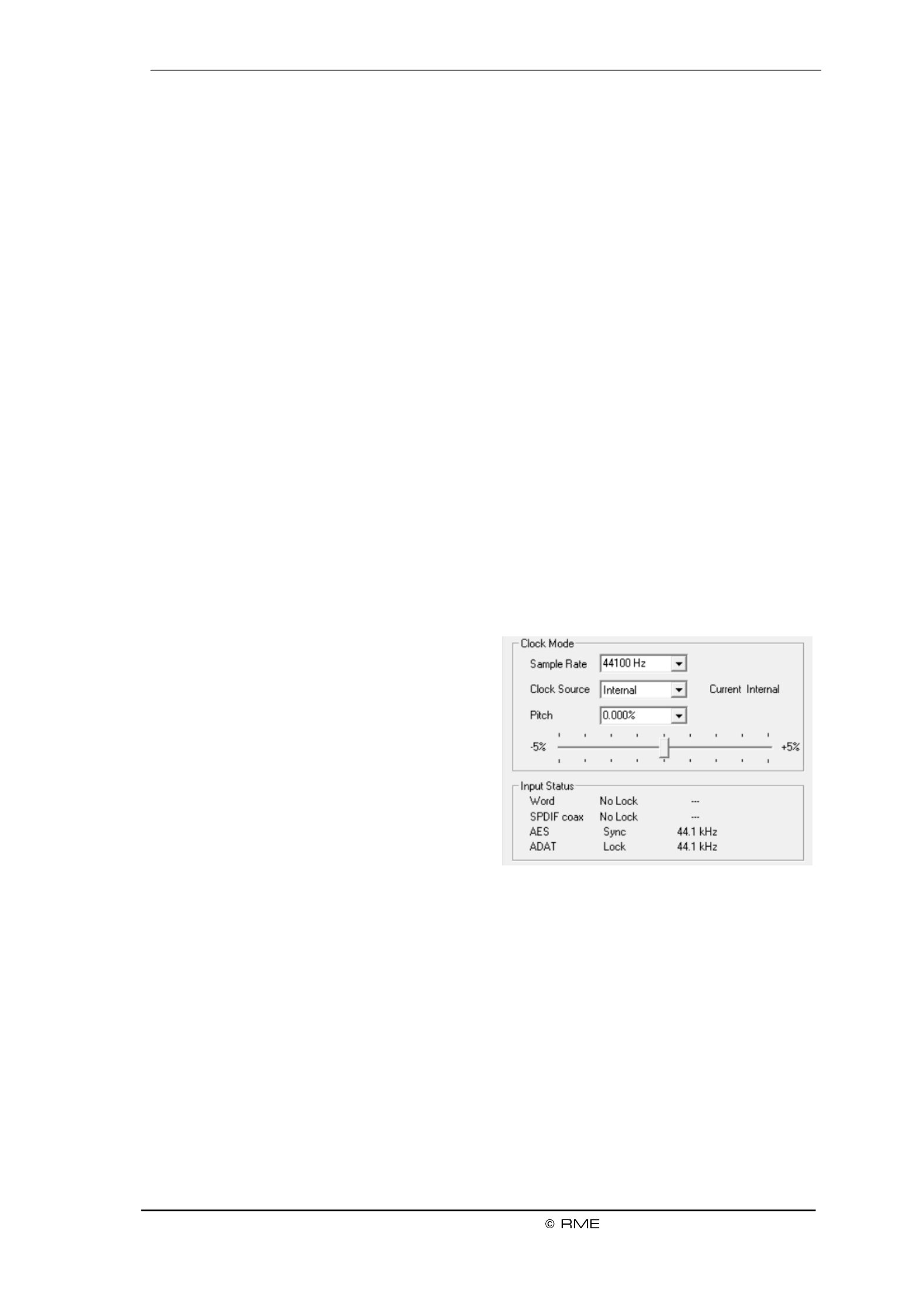
Clock Mode
Sample Rate
Sets the currently used sample rate. Oers a central and comfortable way of conguring the
sample rate of all WDM devices to the same value, as since Vista the audio software is no long-
er allowed to set the sample rate. However, an ASIO program can still set the sample rate by
itself.
During record/playback the selection is greyed out, so no change is possible.
Clock Source
The unit can be congured to use its own clock (Internal = Master), or one of the input signals
(Word, SPDIF, AES, ADAT). If the selected source isn't available (Input Status No Lock), the
unit will change to the next available one (AutoSync). If none is available then the internal clock
is used. The current clock source is displayed . to the right
Pitch
More information on Pitch is available in chapter 7 .2.
Input Status
Indicates for each input (Word SPDIF coaxial, AES, ADAT) whether there is a valid signal ,
(Lock, No Lock), or if there is a valid synchronous signal (Sync). The third column shows the and
sample frequency detected by the hardware (coarse recognition, 32 kHz, 44.1 kHz, 48 kHz etc.).
7.2 Pitch
Usually soundcards and audio interfaces generate their internal clock (master mode) by a
quartz. Therefore the internal clock can be set to 44.1 kHz or 48 kHz, but not to a value in be-
tween. SteadyClock, RME's sensational Low Jitter Clock System, is based on a Direct Digital
Synthesizer (DDS). This superior circuitry can generate nearly any frequency with highest preci-
sion.
The section Pitch includes both a list of typical video frequencies (so called pull up/pull down at
0.1% and 4%) and a fader to freely change the basic sample rate in steps of 1 Hz (!) over a
range of +/- 5%.
The Pitch function requires the Fireface to be in clock mode Master! The frequency setting
will only be applied to this one specic Fireface!
Changing the sample rate during record/playback often results in a loss of audio, or brings
up warning messages of the audio software. Therefore the desired sample rate should be
set at least coarsely before starting the software.
Coarse
Coarse modication in steps of 50 Hz
is done by clicking with the mouse to
the left and right of the fader knob.
Fine
Fine modication in steps of 1 Hz is
done by using the left/right cursor
keys.
Reset
Ctrl key plus left mouse click.

20
User's Guide Fireface UCX II
!
!
Application examples
Pitch allows for a simultaneous change of speed and tune during record and playback. From
alignment to other sources up to creative eects everything is possible. –
Pitch enables you to intentionally de-tune the complete DAW. This way, the DAW can match
instruments which have a wrong or unchangeable tuning.
7.3 Option WDM Devices
The area WDM Devices gives conguration access, a status display showing the number of
currently enabled WDM devices, and a listbox to choose or Stereo Multi-Channel devices. The
number represents both record and playback devices, so ‘1’ means one input and one output
device.
WDM streaming is Microsoft's current driver and audio system, directly embedded into the oper-
ating system.
Several programs do not oer any direct device selection. Instead they use the playback device
selected in Windows under <Control Panel/ Sound/ Playback>.
Activating all stereo devices at once cause temporary freez d15 may ing or ‘not respon ing’
eects. Therefore activate only the ones which are really needed.
After leaving the dialog with OK the WDM devices are reloaded so Windows sees their new
properties.
Multi-Channel using WDM
The WDM Streaming device (Analog 1+2) of the RME driver can operate as usual Loudspeaker
stereo device, or as up to 8-channel device. Using a multi-channel WDM device allows for the
use of multi-channel playback with specialized software as well as Surround sound from DVD or
Blu-Ray player software.
An 8-channel playback using the Windows Media Player requires the speaker setup 7.1 Sur-
round. Control Panel /Sound /Playback /Loudspeaker /Congure <. Congure as follows: >
8. Operation and Usage
8.1 Playback
In the audio application being used, Fireface UCX II must be selected as output device. This can
often be found in the or menus under Options, Preferences Settings Playback Device, Audio
Devices, Audio etc.
WDM playback devices are not available if the number of WDM devices is set to 0 in the
Settings dialog.
We recommend switching all system sounds o (via > <). Al tControl Panel /Sounds though he
Fireface UCX II comes with extensive support for system audio, setting it to be the Default De-
vice for playback could cause problems when working with ASIO.
Increasing the number and/or size of audio buers may prevent the audio signal from breaking
up, but also increases latency i.e. output is delayed. For synchronized playback of audio and
MIDI (or similar), be sure to activate the checkbox ‘Get pos tion from audio driver’.i

User's Guide Fireface UCX II
21
!
Note: Since Windows Vista the audio application can no longer control the sample rate under
WDM. Therefore the driver of the Fireface UCX II includes a way to set the sample rate globally
for all WDM devices within the Settings dialog, see chapter 7 As the change within the system .1.
requires some time, record/playback should not be started immediately, but only after at least 5
seconds after a change.
Tip: the current CPU load can be used to determine if the audio subsystem has nished the re-
conguration.
8.2 DVD-Playback (AC-3/DTS)
Popular DVD software players can send ir audio data stream to any AC-3/DTS capable re-the
ceiver via the Fireface UCX II SPDIF output.
The sample rate must be set to 48 kHz in the UCX II Settings dialog, or the software will only
playback the down-mixed analog signal via SPDIF.
In some cases UCX II device has to be selected in >an output Control Panel / Sound / Play-
back< Default and be set as for the software cognize it. to re
The DVD software's audio properties now show the options 'SPDIF Out' or similar. When select-
ing it, the software will transfer the non-decoded digital multichannel data stream to the Fireface.
Note: This 'SPDIF' signal sounds like chopped noise at highest level. Try to avoid mixing and
routing the signal to your loudspeakers, as they might get damaged.
Multichannel
DVD software player can also operate as software decoder, sending a DVD's multichannel data
stream directly to the analog outputs of the Fireface UCX II. For this to work select the WDM
playback device ’Loudspeaker’ of the Fireface UCX II > < as in Control Panel/ Sound/ Playback
Default.
The playback software’s audio properties now list several multichannel modes. If one of these is
selected, the software sends the decoded analog multichannel data to the Fireface UCX II. To-
talMix can then be used to play back via any desired output channels.
The typical channel assignment for surround playback is:
1 2 3 4 – Left – Right – Center - LFE (Low Frequency Eects)
5 6 - SL (Surround Left) - SR (Surround Right)
Note 1: Selecting the Fireface to be used as system playback device is against our recommen-
dation, as professional interfaces should not be disturbed by system events. Make sure to re-
assign the selection after usage or to disable any system sounds (tab Sounds, scheme 'No au-
dio').
Note 2: The DVD player will be synced backwards from the Fireface. This means when using
AutoSync and/or word clock, the playback speed and pitch follows the incoming clock signal.

22
User's Guide Fireface UCX II
8.3 Channel Count under WDM
The Fireface ADAT optical ports support sample rates of up to kHz. For this to work single-192
channel data is spread to two or four ADAT channels using the Sample Multiplexing technique.
This reduces the number of available ADAT channels from 8 to 4 or 2 per ADAT port.
Whenever the Fireface changes into Double Speed (88.2/96 kHz) or Quad Speed mode
(176.4/192 kHz) all devices no longer available vanish automatically.
WDM Stereo device
Double Speed
Quad Speed
Fireface Analog (1+2)
Fireface Analog (1+2)
Fireface Analog (1+2)
Fireface Analog (3+4)
Fireface Analog (3+4)
Fireface Analog (3+4)
Fireface Analog (5+6)
Fireface Analog (5+6)
Fireface Analog (5+6)
Fireface Analog (7+8)
Fireface Analog (7+8)
Fireface Analog (7+8)
Fireface SPDIF
Fireface SPDIF
Fireface SPDIF
Fireface AES
Fireface AES
Fireface AES
Fireface ADAT 1 (1+ 2)
Fireface ADAT 1 (1+2)
Fireface ADAT 1 (1+2)
Fireface ADAT 1 (3+4)
Fireface ADAT 1 (3+4)
Fireface ADAT 1 (3+4)
Fireface ADAT 1 (5+6)
Fireface ADAT 1 (5+6)
Fireface ADAT 1 (5+6)
Fireface ADAT 1 (7+8)
Fireface ADAT 1 (7+8)
Fireface ADAT 1 (7+8)
8.4 Multi-client Operation
RME audio interfaces support multi-client operation. Several programs can be used at the same
time. The formats ASIO and WDM can even be used on the same playback channels simulta-
neously. But as WDM uses a real-time sample rate conversion (ASIO does not), all active ASIO
software has to use the same sample rate.
However, a better overview is maintained by using the channels exclusively. This is no limitation
at all, because TotalMix allows for any output routing, and therefore a playback of multiple soft-
ware on the same hardware outputs.
Inputs can be used from an unlimited number of WDM and ASIO software at the same time, as
the driver simply sends the data to all applications simultaneously.
RME's sophisticated tool is an exception to this rule. It operates like an ASIO host, DIGICheck
using a special technique to access playback channels directly. Therefore DIGICheck is able to
analyse and display playback data from any software, no matter which format uses. it
User's Guide Fireface UCX II
23
8.5 Analog Recording
For recordings via the analog inputs the corresponding record device has to be chosen (Fireface
UCX II Analog (x+x)).
The input sensitivity of the rear inputs can be changed in two steps and with adjustable gain in
TotalMix (Input Channel Settings, Level), assuring the highest signal to noise ratio will be
achieved. A further optimization can be achieved by adjusting the source itself. Raise the
source’s output level until the peak level m –eters in TotalMix reach about 3 dB.
The level of the front- de analog inputs can be optimized via TotalMix (Input Channel Settings, si
Gain), or directly at the Fireface UCX II by the key Mic/Gain and the encoders 1/2. The multi-
colour level meters shown on the display also provide useful information about the current level
state.
Further information is found in chapter 19.
It often makes sense to monitor the input signal or send it directly to the output. This can be
done at zero latency using (see chapter 25 TotalMix FX ).
An control of real-time monitoriautomated ng can be achieved by Steinberg’s ASIO protocol with
RME’s ASIO drivers and all ASIO 2.0 compatible programs. When 'ASIO Direct Monitoring' has
been switched on, the input signal is routed in real-time to the output whenever a recording is
started (punch-in).
8.6 Digital Recording
Unlike analog soundcards which produce empty wave files (or noise) when no input signal is
present, digital interfaces always need a valid input signal to start recording.
Taking this into account, RME added a compre-
hensive I/O signal status display to the Fireface
UCX II, showing sample frequency, lock and
sync status for every input, and several status-
fields in the unit’s display.
The sample frequency shown in the elds Clock
Mode and Input Status of the Settings dialog is
useful as a quick display of the current configu-
ration of the unit and the connected external
equipment. If no sample frequency is recog-
nized, it will read ‘No Lock’.
This way, conguring any suitable audio application for digital recording is simple. After selecting
the correct input, Fireface UCX II splays the current sample frequency. This parameter can di
then be changed in the application’s audio attributes (or similar) dialog.

24
User's Guide Fireface UCX II
!
8.7 Clock Modes - Synchronization
In the digital world, all devices must be either Master (clock source) or Slave (clock receiver).
Whenever several devices are linked within a system, there must always be a single master
clock.
A digital system can only have one master! If the Fireface’s clock mode is set to 'Master', all
other devices must be set to ‘Slave’.
The Fireface UCX II utilizes a very user-friendly, intelligent clock control, called AutoSync. In
AutoSync mode, the system constantly scans the digital input for a valid signal. If any valid signal
is found, the Fireface switches from the internal quartz ( Current Internal) to a Clock Source –
clock extracted from the input signal ( Current ADAT, SPDIF, AES or Word). The Clock Source –
dierence to a usual slave mode is that whenever the clock reference fails, the system will au-
tomatically use its internal clock and operate in clock mode Master.
AutoSync guarantees that record and record-while-play will always work correctly. In certain
cases however, AutoSync may cause feedback in the digital carrier, so synchronization breaks
down. To remedy this, switch the Fireface clock mode to r . ‘Inte nal’
RME’s exclusive SyncCheck technology enables an easy to use check and display of the cur-
rent clock status. SyncCheck indicates whether there is a valid signal (Lock, No Lock) for each
input (Word Clock, SPDIF, ADAT, AES), or if there is a valid synchronous signal (Sync). and
See chapter 40.1.
Via Clock Source a preferred input can be dened. As long as the Fireface sees a valid signal
there, this input will be designated as the sync source, otherwise the other inputs will be scanned
in turn. If none of the inputs are receiving a valid signal, the Fireface automatically switches
clock mode to ‘Internal’.
Under WDM the Fireface will (has to) set the
sample rate. Therefore the error shown to the
right can occur. An AES, SPDIF or ADAT
signal with a sample rate of kHz is used as sync source, but Windows audio had been set to 48
44100 Hz before. The red color of the text label signals the error condition, and prompts the user
to set 000 Hz manually as sample rate. 48
Under ASIO the audio software sets the sample rate, so that such an error will usually not hap-
pen – but it can too. In slave mode the external sample rate has priority. Feeding 44.1 kHz will
prevent the ASIO software to set 48 kHz obviously, as the only way to do so would be to enter –
a dierent clock mode (Master/Internal).
In practice, SyncCheck provides the user with an easy way of checking whether all digital devic-
es connected to the system are properly congured. With SyncCheck, finally anyone can master
this common source of error, previously one of the most complex issues in the digital studio
world.
User's Guide Fireface UCX II
25
9. Operation under ASIO
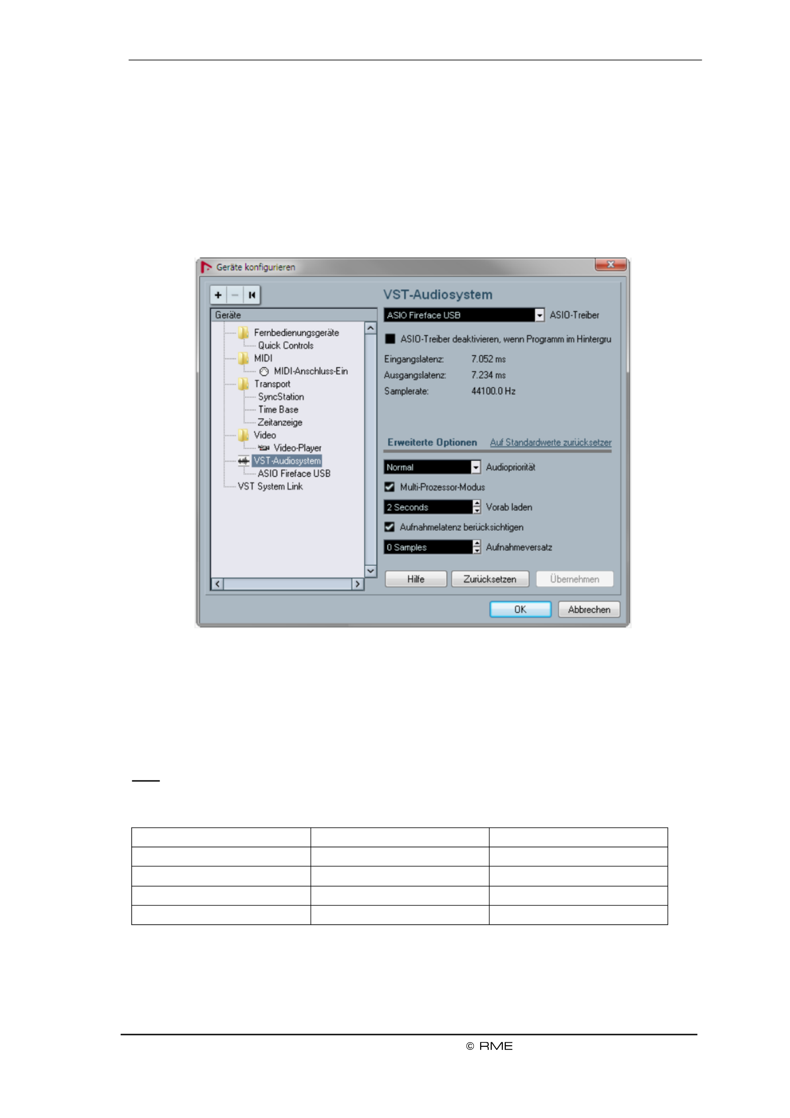
9.1 General
Start the ASIO software and select ASIO MADIface USB as the audio I/O device or the ASIO
audio driver.
The Fireface UCX II supports (ADM). ASIO Direct Monitoring
The Fireface UCX II MIDI I/Os can be used with both MME MIDI and DirectMusic MIDI.
9.2 Channel Count under ASIO
At a sample rate of 88.2 or 96 kHz, the ADAT optical input and outputs operate in S/MUX mode,
so the number of available channels per port is reduced from 8 to 4. At a sample rate of 176.4
and 192 kHz, the ADAT optical input and output operates in S/MUX4 mode, so the number of
available channels is limited to 2.
Note: When changing the sample rate range between Single, Double and Quad Speed the
number of channels presented from the ASIO driver will change too. This may require a reset of
the I/O list in the audio software.
Single Speed
Double Speed
Quad Speed
Fireface Analog 1 8 to
Fireface Analog 1 8 to
Fireface Analog 1 8 to
Fireface SPDIF L / R
Fireface SPDIF L / R
Fireface SPDIF L / R
Fireface AES L / R
Fireface AES L / R
Fireface AES L / R
Fireface ADAT 1 8 to
Fireface ADAT 1 4 to
Fireface ADAT 1 2 to

26
User's Guide Fireface UCX II
9.3 Known Problems
If a computer does not provide sucient CPU-power, and/or sucient USB or PCI bus transfer
rates, sucient PCIe-bus transfer rates, then drop outs, crackling and noise will appear. and/or
Raising the buer size in the Settings dialog of the Fireface UCX II helps in most cases. It is also
recommended to deactivate all PlugIns to verify that these are not the reason for such effects.
Further information is found in chapter . 40 3.
Another common source of trouble is incorrect synchronization. ASIO does not support asyn-
chronous operation, which means that the input and output signals not only have to use the
same sample frequency, but also have to be in sync. All devices connected to the Fireface UCX
II must be properly congured for full duplex operation. As long as SyncCheck (in the Settings
dialog) only displays instead of perly. Lock Sync, the devices have not been set up pro
The same applies when using more than one Fireface UCX II - they all have to be in sync. Else
a periodically repeated noise will be heard.
RME devices support (ADM). Please note that not all programs support ASIO Direct Monitoring
ADM completely or error-free. The most often reported problem is the wrong behaviour of pano-
rama in a stereo channel. Also try to avoid setting the TotalMix FX hardware outputs (third row)
to mono mode. This will most likely break ADM compatibility.
In case of a drift between audio and MIDI, or in case of a xed deviation (MIDI notes placed
close before or behind the correct position), the settings in Cubase/Nuendo have to be changed.
At the time of print the option 'Use System Timestamp' should be activated. The Fireface UCX II
supports both MME MIDI and DirectMusic MIDI. It depends on the used ap ication which one pl
will work better.
10. Using more than one Fireface UCX II
The driver supports up to three Fireface UCX II or a combination of up to three supported inter-
faces. All units have to be in sync, i.e. have to receive valid sync information (either via word
clock or by using AutoSync and feeding synchronized signals).
If one of the Firefaces is set to clock mode Master, all others have to be set to clock mode
AutoSync, and have to be synced from the master, for example by feeding word clock. The
clock modes of all units have to be set up correctly in the Fireface Settings dialog.
If all units are fed with a synchronous clock, i.e. all units show in their Settings dialog, Sync
all channels can be used at once. This is especially easy to handle under ASIO, as the ASIO
driver presents all units as one.
Please be aware that operating more than one Fireface UCX II may cause resource problems
on the computer side.
Note: TotalMix is part of the hardware of each Fireface. Up to three mixers are available, but
these are separated and can't interchange data. Therefore a global mixer for all units is not pos-
sible.

User's Guide Fireface UCX II
27
11. DIGICheck Windows
The DIGICheck software is a unique utility developed for testing, measuring and analysing digital
audio streams. Although this Windows software is fairly self-explanatory, it still includes a com-
prehensive online help. DIGICheck 5.94 operates as multi-client ASIO host, therefore can be
used in parallel to any software, be it WDM or ASIO, with both inputs and outputs (!). The follow-
ing is a short summary of the currently available functions:
. High precision 24-bit resolution, 2/8/20 channels. Application examples: Peak Level Meter
level measurement, RMS level measurement, over-detection, phase correlation measure-
ment, dynamic range and signal- -noise ratios, RMS to peak dierence (loudness), long to
term peak measurement, input check. Oversampling mode for levels higher than 0 dBFS.
Vertical and horizontal mode. Slow RMS and RLB weighting lter. Supports visualization ac-
cording to the K-System.
for . Reference Level Meter freely coHardware Level Meter Input, Playback and Output n-
gurable, causing near zero CPU load, because calculated from the Fireface hardware.
Spectral Analyser. World wide unique 10-, 20- or 30-band display in analog bandpass-filter
technology. 192 kHz-capable!
Vector Audio Scope. World wide unique Goniometer showing the typical afterglow of a os-
cilloscope-tube. Includes Correlation meter and level meter.
. Spectral Analyser, Level Meter and Vector Audio Scope in a single window. Totalyser
Professional Surround Level Meter with extended correlation analSurround Audio Scope. y-
sis, ITU weighting and ITU summing meter.
. For standardized loudness measurements. ITU1770/EBU R128 Meter
. Shows the true resolution of audio signals as well as errors and DC Bit Statistics & Noise
oset. Includes Signal to Noise measurement in dB and dBA, plus DC measurement.
. Detailed analysis and display of SPDIF and AES/EBU Channel Channel Status Display
Status data.
-term recording of all channels at lowest system load. Global Record. Long
Open as many measurement windows as you like, on any chaCompletely multi-client. n-
nels and inputs or outputs!
DIGICheck is free but works only with RME interfaces. It is constantly improved and updated.
The latest version is always available on our website , section www.rme-audio.com Downloads
/ Software.

User's Guide Fireface UCX II
29
User's Guide
Installation and Operation Mac OS X –

30
User's Guide Fireface UCX II
!
13. Hardware, Driver and Firmware Installation
13.1 Hardware and Driver Installation
After the Fireface has been connected to the computer and switched on install the drivers.
RME is constantly improving the drivers. Please download the latest drivers from the RME web-
site at . Unzip the downloaded le and start the driver installation by http://rme.to/downloads
double-clicking . Fireface USB.pkg
During driver installation the programs (TotalMix FX) are Totalmix and Fireface USB Settings
copied to the Applications folder. They will automatically start into the dock if a Fireface UCX II is
connected. A reboot of the computer is not required.
Driver Updates do not require to remove the existing drivers. Simply install the new driver over
the existing one.
For the latest M1 drivers for macOS please read the included readme carefully, as on
such machines the driver installation requires additional steps to enable third party
kernel extensions
13.2 -installing the Drivers De
In case of problems the driver les can be deleted manually by dragging them to the trash bin:
USB
/Applications/Fireface USB Settings
/Applications/Totalmix
/System/Library/Extensions/FirefaceUSB.kext
/Users/username/Library/Preferences/de.rme-audio.TotalmixFX.plist
/Users/username/Library/Preferences/de.rme-audio.Fireface_USB_Settings.plist
/Library/LaunchAgents/de.rme-audio.refaceUSBAgent.plist
Under the latest Mac OS the User/Library folder is not visible in the Finder. To unhide it start
Finder, click on the menu item Go. Hold down the option (alt) key, then click on Library.
13.3 Firmware Update
The Flash Update Tool updates the rmware of the Fireface UCX II to the latest version. It re-
quires an already installed Thunderbolt or USB driver.
Start the program . The Flash Update Tool displays the current revision of Fireface USB Flash
the UCX II rmware, and whether it needs an update or not. If so, simply press the 'Update' but-
ton. A progress bar will indicate when the ash process is nished (Verify Ok).
After the update the Fireface UCX II needs to be reset. This is done by powering down the
Fireface for a few seconds. A reboot of the computer is not necessary.
When the update fails (status: failure), the unit's second BIOS will be used from the next cold
boot on (Secure BIOS Technology). Therefore the unit stays fully functional. The flash process
should then be tried again on a dierent computer.

User's Guide Fireface UCX II
31
14. Conguring the Fireface UCX II
14.1 Settings Dialog
Conguring the Fireface is done via its own settings dialog. Start the program Fireface USB
Settings. The mixer of the Fireface UCX II (TotalMix FX) can be congured by starting the pro-
gram . Totalmix
The Fireface’s hardware offers a number of helpful, practical functions and options to suit many
dierent requirements. The following is available in the 'Settings' dialog:
Operation of the DSP
Conguration of digital I/Os
Current sample rate
Synchronization behaviour
State of input and output
Any changes performed in the
Settings dialog are applied imme-
diately - conrmation (e.g. by exit-
ing the dialog) is not required.
However, settings should not be
changed during playback or record
if it can be avoided, as this can
cause unwanted noises.
Use the drop down menu Proper-
ties For to select the unit to be
congured.
On the right of it the current rm-
ware and driver version of the
Fireface UCX II is shown.
Input Options
Word Clock Input
This option switches the BNC
socket into word clock put mode in
Word Clock - Termination
Checking this option terminates
the word clock input internally with 75 Ohms.
DSP Record EQ+D–
Switches EQ and Dynamics of all input channels into the recording path. In case Loopback has
been activated the EQ and Dynamics of the Output channel are within the recording path. See
also chapter 27.6.

32
User's Guide Fireface UCX II
Output Options
SPDIF Format
The SPDIF coaxial signal can have the Channel Status Professional or Consumer. For output
further details please refer to chapter 21.3.
Optical Out
The optical TOSLINK output can operate as ADAT or SPDIF outpu t.
Clock Options
Word Clock I/O Single Speed –
The word clock output signal usu-
ally equals the current sample
rate. Selecting caus-Single Speed
es the output signal to always stay
within the range of 32 kHz to 48
kHz. So at 96 kHz and 192 kHz
sample rate, the output word clock
is 48 kHz.
The word clock input usually
adapts to the current sample rate
range. For example a 48 kHz word
signal can be used to sync the
internal clock of 96 and 192 kHz.
When the option is Single Speed
not checked sam-the interface’s
ple rate follows the external sam-
ple rate directly. A word signal of
192 kHz will cause the UCX II to
use 192 kHz internally. This fea-
ture is also called Follow Clock.
Sample Rate
Used to set the current sample
rate. This is the same setting as in
the Audio MIDI Setup, just added
here for your convenience.
Clock Source
The unit can be congured to use its own clock (Internal = Master), or one of the input signals
(Word, SPDIF, AES, ADAT). If the selected source isn't available (Input Status No Lock), the
unit will change to the next available one (AutoSync). If none is available then the internal clock
is used. The current clock source is displayed below.
Input Status
Indicates for i s Word, SPDIF, ADAT whether a valid signal (Lock, No Lock) or a nput AES and
valid synchronous signal (Sync) is present. The third column shows the sample frequency and
detected by the hardware (coarse recognition, 32 kHz, 44.1 kHz, 48 kHz etc.).
Short Safety Oset
Reduces overall latency by using smaller Safety Osets (12 samples instead of 24 samples).
Change is performed in real-time. Smaller Safety Osets might cause clicks and dropouts.

User's Guide Fireface UCX II
33
!
14.2 Clock Modes - Synchronization
In the digital world, all devices must be either Master (clock source) or Slave (clock receiver).
Whenever several devices are linked in a system, there must always be a single master clock.
A digital system can only have one master! If the Fireface’s clock mode is set to 'Master', all
other devices must be set to ‘Slave’.
The Fireface UCX II utilizes a very user-friendly, intelligent clock control, called AutoSync. In
AutoSync mode, the system constantly scans the digital input for a valid signal. If any valid signal
is found, the Fireface switches from the internal quartz ( Current Internal) to a Clock Mode –
clock extracted from the input signal ( Current SPDIF, ADAT, AES or Word). The Clock Mode –
dierence to a usual slave mode is that whenever the clock reference fails, the system will au-
tomatically use its internal clock and operate in clock mode Master.
AutoSync guarantees that record and record-while-play will always work correctly. In certain
cases however, AutoSync may cause feedback in the digital carrier, so synchronization breaks
down. To solve this problem switch the Fireface clock mode to Internal . ‘ ’
RME’s exclusive SyncCheck technology enables an easy to use check and display of the cur-
rent clock status. indicates whether there is a valid signal (Lock, No Lock) for each SyncCheck
input (Word Clock, SPDIF, ADAT, AES), or if there is a valid synchronous signal (Sync). In and
the eld the clock reference is shown. See chapter Clock Mode 40.1.
Via a preferred input can be dened. As long as the Fireface sees a valid signal Clock Source
there, this input will be designated as the sync source, otherwise the other inputs will be scanned
in turn. If none of the inputs are receiving a valid signal, the Fireface automatically switches
clock mode to ‘Internal’.
In some situations changing the clock mode can not be
avoided. Example: An ADAT recorder is connected to
the ADAT input (ADAT immediately becomes the Au-
toSync source) and a CD player is connected to the
AES input. Try recording a few samples from the CD
and you will be disappointed - few CD players can be
synchronized. The samples will inevitably be corrupted,
because the signal from the CD player is read with the
clock from the ADAT. In this case the Clock Source
should be temporarily set to . AES
In practice, SyncCheck provides the user with an easy way of checking whether all digital devic-
es connected to the system are properly congured. With SyncCheck, nally anyone can master
this common source of error, previously one of the most complex issues in the digital studio
world.

34
User's Guide Fireface UCX II
15. Mac OS X FAQ
15.1 MIDI doesn't work
In some cases the applications do not show the MIDI port. The reason for this is usually visible
within the . It displays no RME MIDI device, or the device is greyed out and Audio MIDI Setup
therefore inactive. Mostly, removing the greyed out device and searching for MIDI devices again
will solve the problem.
The Fireface is class compliant. Therefore it comes without a driver. OS X recognizes it as ’ MIDI
MIDI device and will be using it with the driver included in the operating system.
15.2 Repairing Disk Permissions
Repairing permission can solve problems with the installation process - plus many others. To do
this, launch located in . Select your system drive in the drive/volume list to Disk Utility Utilities
the left. The First Aid tab to the right now allows you to check and repair disk permissions.
15.3 Supported Sample Rates
RME's Mac OS X driver supports all sampling frequencies provided by the hardware. This in-
cludes . 32 kHz and 64 kHz, and even 128 kHz, 176.4 kHz and 192 kHz
But not any software will support all the hardware's sample rates. The hardware's capabilities
can easily be verified in the . Select under Audio MIDI Setup Audio devices Properties of: and
choose the Fireface. A click on will list the supported sample frequencies. Format
15.4 Channel Count under Core Audio
At a sample rate of 88.2 or 96 kHz, the ADAT optical input and outputs operate in S/MUX mode,
so the number of available channels per port is reduced from 8 to 4. At a sample rate of 176.4
and 192 kHz, the ADAT optical input and output operates in S/MUX4 mode, so the number of
available channels is limited to 2.
It is not possible to change the number of Core Audio channels without a reboot of the comput-
er. Therefore whenever the Fireface changes into Double Speed (88.2/96 kHz) or Quad Speed
mode (176.4/192 kHz) all channels stay present, but become partly inactive.
Single Speed
Double Speed
Quad Speed
Fireface Analog 1 8 to
Fireface Analog 1 8 to
Fireface Analog 1 8 to
Fireface SPDIF
Fireface SPDIF
Fireface SPDIF
Fireface A ES
Fireface AES
Fireface AES
Fireface ADAT 1 8 to
Fireface ADAT 1 4 to
Fireface ADAT 1 2 to

User's Guide Fireface UCX II
35
15.5 Various Information
Programs that don't support card or channel selection will use the device osen as ch Input and
Output System Preferences Sound in the – panel.
Via Fireface can be configured for the system Launchpad Other Audio MIDI Setup– – the
wide usage in more detail.
Programs that don't support channel selection will always use channels 1/2, the rst stereo pair.
To access other inputs, use the following workaround with TotalMix: route the desired input sig-
nal to output channels 1/2. In the channel settings of outputs 1/2 activate . Result: the Loopback
desired input signal is now available at input channel 1/2, without further delay/latency.
Use to freely congure the stereo or multichannel playback to any availCongure Speakers a-
ble channels.
16. Using more than one Fireface
OS X supports the usage of more than one audio device within an audio software. This is done
via the Core Audio functi , which allows to combine several devices into on Aggregate Devices
one.
The current driver supports up to three Fireface UCX II. All units have to be in sync, i.e. have to
receive valid sync information either via word clock or by feeding synchronized signals.
If one of the Firefaces is set to clock mode Master, all others have to be set to clock mode
Slave, and have to be synced from the master, for example by feeding word clock. The
clock modes of all units have to be set up correctly in the Fireface Settings dialog.
If all units are fed with a synchronous clock, i.e. all units show in their Settings dialog, Sync
all channels can be used at once.
Note: TotalMix is part of the Fireface hardware. Up to three mixers are available, but these are
separated and can't interchange data. Therefore a global mixer for all units is not possible.
Please be aware that operating more than one Fireface UCX II may cause resource problems
on the computer side.

36
User's Guide Fireface UCX II
17. DIGICheck NG Mac
The DIGICheck software is a unique utility developed for testing, measuring and analysing digital
audio streams. Although the software is fairly self-explanatory, it still includes a compre nsive he
online help. DIGICheck NG operates in parallel to any software, showing all input data. Th0.86 e
following is a short summary of the currently available functions:
. High precision 24-bit resolution, 2/8/ channels. Application examples: Peak Level Meter 20
level measurement, RMS level measurement, over-detection, phase correlation measure-
ment, dynamic range and signal- -noise ratios, RMS to peak dierence (loudness), long to
term peak measurement, input check. Oversampling mode for levels higher than 0 dBFS.
Vertical and horizontal mode. Slow RMS and RLB weighting filter. Supports visualization ac-
cordi -System. ng to the K
for . Reference Level Meter freely coHardware Level Meter Input, Playback and Output n-
gurable, causing near zero CPU load, because calculated from the Fireface hardware.
Spectral Analyser. World wide unique 10-, 20- or 30-band display in analog bandpass lter
technology. 192 kHz-capable!
Vector Audio Scope. World wide unique Goniometer showing the typical afterglow of a os-
cilloscope-tube. Includes Correlation meter and level meter.
. Spectral Analyser, Level Meter and Vector Audio Scope in a single window. Totalyser
Professional Surround Level Meter with extended correlation analSurround Audio Scope. y-
sis, ITU weighting and ITU summing meter.
. For standardized loudness measurements. ITU1770/EBU R128 Meter
. Shows the true resolution of audio signals as well as errors and DC Bit Statistics & Noise
oset. Includes Signal to Noise measurement in dB and dBA, plus DC measurement.
Open as many measurement windows as you like, on any chaCompletely multi-client. n-
nels and inputs or outputs!
DIGICheck is constantly updated. The latest version is always available on our website
www.rme-audio.com Downloads / DIGICheck, section .

User's Guide Fireface UCX II
37
18. Hotline Troubleshooting–
The newest information can always be found on our website www.rme-audio.com, section FAQ,
latest Additions.
The unit and drivers have been installed correctly, but playback does not work:
Has Fireface been selected as current playback device in the audio application?
The 8 ADAT channels don’t seem to work
The optical output ADAT has been switched to SPDIF. The ADAT playback devices are still
usable by routing and mixing them in TotalMix to other outputs.
Playback works, but record doesn’t:
Check that there is a valid signal at the input. If so, the current sample frequency is displayed
in the Settings dialog.
Check whether the Fireface UCX II has been selected as recording device in the audio appli-
cation.
Check whether the sample frequency set in the audio application (‘Recording properties’ or
similar) matches the input signal.
Check that cables/devices have not been connected in a closed loop. If so, set the system’s
clock mode to ‘Master’.
Crackle during record or playback:
Increase the number and size of buers in the application.
Try dierent cables (coaxial or optical) to rule out any defects here.
Check that cables/devices have not been connected in a closed loop. If so, set the system’s
clock mode to ‘Master’.
Check the Settings dialog for displayed Errors.
Possible causes for a Fireface not working
The USB cable is not, or not correctly inserted into the socket
Driver installation and Settings dialog/TotalMix work, but a playback or record is not possible
While recognition and control of the device are low bandwidth applications, playback/record
needs the full transmission performance. Therefore, defective USB cables with limited
transmission bandwidth can cause such an error scheme.

38
User's Guide Fireface UCX II

User's Guide Fireface UCX II
39
User's Guide
Inputs and Outputs

40
User's Guide Fireface UCX II
!
19. Analog Inputs
19.1 Line Rear
The Fireface has four balanced Line inputs as 1/4" TRS jacks on the back of the unit. The elec-
tronic input stage is built in a servo balanced design which handles unbalanced (mono jacks)
and balanced (stereo jacks) correctly, automatically adjusting the level reference.
When using unbalanced cables with TRS jacks: be sure to connect the 'ring' contact of the
TRS jack to ground. Otherwise noise may occur, caused by the unconnected negative input
of the balanced input.
One of the main issues when working with an AD-converter is to maintain the full dynamic range
within the best operating level. Therefore the Fireface UCX II internally uses hi-quality electronic
switches, which allow for a perfect adaptation of all rear inputs individually to the most often
used studio levels. The Fireface UCX II oers the following level references:
Reference
0 dBFS @
Max Gain
0 dBFS @
+19 dBu
+19 dBu
12 dB
+7 u dB
+ dBu 13
+13 dBu
12 dB
+1 dBu
A reference level of +4 u can be set by using + dBu and adding 9 dB of gain with the Gain dB 13
knob in the TotalMix FX channel settings.
19.2 Microphone / Line Front
The two balanced microphone inputs of the Fireface UCX II oer a digitally controlled gain of 0
to 75 via XLR/TRS combo jacks. The gain range is 0 to 75 dB, adjustable in steps of 1 dB. dB
The soft switching, hi-current Phantom power (48 Volt), switchable per channel, provides a pro-
fessional handling of condensor mics. Up to a level of +18 dBu, the front XLR input can also be
used as balanced and unbalanced Line input.
The TRS jack of the two combo jacks are free of phantom power and fully compatible to unbal-s
anced (mono jack) sources. They have a xed level attenuation of 6 . The maximum input dB
level is therefore +24 dBu, balanced and unbalanced.
Channels 1 4 feature an automatic overload protection tries to keep a headroom of to . AutoSet
6 dB. Levels higher than -6 dBFS will permanently reduce the gain. To check set the channels to
a high gain and apply an input signal. The button will quickly rotate back to a gain that is appro-
priate.
While with extreme overloads distortion will occur for the fraction of a second before the level is
set correctly AutoSet works quite well in real-world applications and prevents distorted record-,
ings reliably.
Using stereo channels AutoSet operates ganged. AutoSet can be
activated in TM FX or directly at the unit in the channel settings. A
push on Encoder 1/2 toggles AS on/o.
As soon as AutoSet reduces the gain the label AS, shown in the front
display, changes its colour from black to blue.

User's Guide Fireface UCX II
41
19.3 Instrument / Line Front
Inputs 3/4 of the Fireface UCX II are exceptionally flexible. Several gain and impedance options
make them the ideal receivers for both line and instrument signals.
Line
Inputs 3/4 have balanced line inputs as 1/4" TRS jacks. The electronic input stage is built in a
servo balanced design which handles unbalanced (mono jacks) and balanced (stereo jacks)
correctly, automatically adjusting the level reference.
Inputs 3/4 operate in perfect harmony with the rear inputs 5 to 8, as they are identical in all tech-
nical specications.
Adjustable Input Gain
Via in TotalMix channel settings, or by using the rotary encoder on Gain
the front, an additional gain can be applied to the input signals of chan-
nels 3/4. The gain range is 0 dB up to 12 dB, in steps of 0.5 dB. This
option not only allows for the use of sources with low level output signals,
but also for example to adjust the balance between channel 3 and 4 pre-
cisely, already before the recording takes place.
Two reference levels plus 12 dB adjustable gain offer universal connec-
tivity. Be it keyboards, samplers, CD players or what ever one likes to
connect: These inputs handle levels from dBu up to + dBu and also +1 19
perfectly handle your
Instrument
The main dierence between a line- and instrument input is the input's
impedance. Via the option in the TotalMix channel settings, the input Inst
impedance changes from 10 kOhm to 1 MOhm (also called Hi- . At the Z)
same time the input sensitivity rises by 6 dB.
The instrument input operates balancedun . Please don’t use (stereo) TRS jacks in that mode.
For AutoSet please read chapter 19.2.

42
User's Guide Fireface UCX II
20. Analog Outputs
20.1 Line
The short circuit protected, low impedance line outputs of channels 1 6 are available as 1/4" to
TRS jacks on the back of the unit. The electronic output stage is built in a servo balanced design
which handles unbalanced (mono jacks) and balanced (stereo jacks) correctly.
To maintain an optimum level for devices connected to the analog outputs, the Fireface UCX II
internally uses hi-quality electronic switches, which allow for a perfect tputs adaptation of all ou
individually to the three most often used studio levels.
As with the analog inputs, the analog output levels are dened to maintain a problem-free opera-
tion with most other devices.
Reference
0 dBFS @
Older RME units
+19 dBu
+19 dBu
Hi Gain/Lo Gain ( 15 dB HR)
+ dBu 13
+13 dBu
+4 dBu (9 dB HR)
+4 u dB
+4 u dB
-10 dBV (12 dB HR)
In older RME devices, the references refer to a working level plus headroom (HR). In the UCX II
the maximum level is used as name instead, which is less confusing in our opinion. The levels of
the table are identical in each respective case and thus fully compatible.
20.2 Headphones / Line Out
Channels of the Fireface are available on the front 1/4" TRS jack. These channels use 7/8 as
the same converters as the other Line outputs, therefore oer the same technical data.
Two hardware-based reference levels are available (set in TotalMix Output Channel Settings,
Level, High or Low). High equals the setting +19 dBu of the other channels, Low equals +4 dBu
(see table above). They can thus also be used as high-quality, unbalanced line outputs.
These outputs are special low impedance types (1 Ohms) perfectly suited for use. , headphone
Setting the output level, i.e. the monitoring volume, is done besides the pre-setting High/Low - –
via TotalMix (Hardware Output, P ) or directly at the unit via the encoder Changing the hones .
monitoring volume is therefore very easy and quickly done.
In case the Phones output should operate as
line outputs, an adapter TRS plug to RCA
phono plugs, or TRS plug to TS plugs is re-
quired.
The pin assignment follows international
standards. The left channel is connected to
the tip, the right channel to the ring of the
TRS jack/plug.

User's Guide Fireface UCX II
43
!
20.3 -coupled Outputs (CV/Gate) DC
All eight analog outputs of the UCX II are DC-coupled. AC coupling via capacitor is common,
both directly after the DAC chip and directly at the output socket. This prevents a xed DC com-
ponent at the output, which could cause negative eects such as popping noise malfunctions or
in other devices that are also DC-coupled. However, it also serves as protection against danger-
ous DC from the outside.
DC coupling has the obvious advantage of allowing the output to operate level-linearly down to 0
Hz. Even at extremely low bass (16 Hz) phase shifts are avoided. DC-coupled inputs are rare,
especially for power ampliers, so a possible DC oset of a playback normally does not cause
serious issues.
In order to realize the outputs stable and reliable (robust) -coupled, the circuitry was de-as DC
signed for low DC-osets and sucient overvoltage protection. That this works has been proven
for years, not only by RME's ADI series.
To be able to generate DC is quite useful in measurement technology, also in connection with
audio. However, DC coupling is especially desirable in combination with analog, electronic
sound generators (synthesizers). These have an input that can control the pitch as well as other
functions via a DC voltage. Control Voltage, short CV, often also CV/Gate (gate determines tone
on or o), CV Filter etc. is mostly based on the voltage range 0 to +5 Volt. If an audio interface
can output such DC voltages then synthesizers can be controlled via suitable software and the
analog outputs of the audio interface.
The DA converters and analog output stages used in the UCX II have a very low DC drift and
generate the DC voltages very reliably and reproducibly, so they are very well suited for this ap-
plication.
Polarity - Phase
Since the outputs (of course) have a correct polarity, and TotalMix fully supports DC (via fader
and level meter), a positive voltage appears at the analog output when a digital positive DC is
played The amount of volta can be measured accurately irectly with any cheap multime-. ge and d
ter.
Negative output voltages should be avoided, because they could theoretically lead to defects
in the CV input. Even if the software used genera only positive signals, a simple phase tes
inversion TotalMix can invert the signal so that a negative voltage is send . in out
Voltage Ranges
Line Out 1-6, unbalanced (mono jack), unloaded:
+19 dBu: +9.5 V, +13 dBu: +4.75 V, +4 dBu: +1.7 V
Phones 7/8, unbalanced, unloaded:
High (+19 dBu): +9.5 V, Low (+4 dBu): +1.7 V
Note: The level meters in TotalMix show DC 3 dB higher due to its factory default setting. This
can be changed by disabling the Settings - Level Meters - RMS +3 dB option in TotalMix FX.

44
User's Guide Fireface UCX II
!
21. Digital Connections
21.1 ADAT
The ADAT optical input of the Fireface UCX II is fully compatible with all ADAT optical outputs.
RME's unsurpassed Bitclock PLL prevents clicks and drop outs even in extreme varipitch opera-
tion, and guarantees a fast and low jitter lock to the digital input signal. A usual TOSLINK cable
is sucient for connection.
ADAT In
Interface for receiving an ADAT signal. Carries the channels 1 to 8. When receiving a Double
Speed signal, this input carries the channels 1 to 4, at Quad Speed the channels 1 and 2.
ADAT Out
Interface for sending an ADAT signal. Transmits channels 1 to 8. When sending a Double
Speed signal, this port carries channels 1 to 4, at Quad Speed the channels 1 and 2. Can also
be a 2 put. used as -channel SPDIF optical out
21.2 AES/EBU
The Fireface UCX II’s digital breakout cable (BO968) provides one XLR AES/EBU input and
output each. Connection is accomplished using balanced cables with XLR plugs. Input and Out-
put are transformer-balanced and ground-free. The incoming channel status is ignored.
AES/EBU (and SPDIF) can contain Emphasis information. Audio signals with Emphasis have a
high frequency boost, requiring high frequency attenuation on playback.
An Emphasis indication gets lost as there exists no standardized interface on computers to
handle this information!
Operation as second SPDIF I/O
Thanks to a highly sensitive input stage
SPDIF coaxial can be fed too by using a sim-
ple cable adapter /XLR. To achieve this, RCA
pins 2 and 3 of a male XLR plug are connect-
ed individually to the two pins of a plug. RCA
The cable shielding is only connected to pin 1
of the XLR - plug. not to the RCA
Using the cable adapter XLR/ described above, devices with coaxial SPDIF interface can RCA
be connected to the AES output of the Fireface UCX II as well. Note that most consumer equip-
ment with phono (SPDIF) inputs will only accept signals having a Channel Status . Consumer In
such cases the above adapter cable will not work.

User's Guide Fireface UCX II
45
!
21.3 SPDIF (Coaxial, Optical)
The Fireface UCX has up to three SPDIF inputs and outputs: coaxial, optical and AES can be II
used simultaneously, with dierent audio signals. Note that the sources have to be synchronous,
as the unit does not have a dedicated sample rate converter.
The SPDIF coaxial input accepts SPDIF and AES/EBU, Consumer as well as Professional for-
mat.
To receive signals in AES/EBU format,
an adapter cable is required. Pins 2 and
3 of a female XLR plug are connected
individually to the two pins of a phono
plug. The cable shielding is connected to
pin 1 of the XLR and the ground contact
of the phono plug.
The optical input automatically switches to SPDIF operation when such a signal is detected. The
audio information is then shown in TotalMix on the first two ADAT channels ADAT 1/2, which are
channels 1 . 3 and 14
SPDIF coaxial Output
Apart from the audio data itself, digital signals in SPDIF or AES/EBU format have a header con-
taining channel status information. False channel status is a common cause of malfunction. The
Fireface UCX II ignores the received header and creates a totally new one for the output signal.
The output SPDIF coaxial can have the Channel Status Consumer or Professional, changed in
the Settings dialog. When selecting Professional, the carrier level is also doubled for better
AES/EBU compatibility.
Operation as second AES/EBU O utput
Professional AES/EBU equipment can be connected to the output SPDIF coaxial thanks to its
format option and a doubled output voltage. Output cables should have the same Professional
pinout as those used for input (see above), but with a male XLR plug instead of a female one.
SPDIF optical output
To send out SPDIF from the optical output, select the option in Output Format Optical SPDIF–
the Settings dialog. The output signal in TotalMix has to be present on the ADAT channels 1/ 2.
Note that most consumer HiFi equipment (with optical or phono SPDIF inputs) will only ac-
cept signals in ‘Consumer’ format!
Therefore in SPDIF mode the optical output is xed to Consumer status.
21.4 MIDI
Fireface UCX II offers MIDI I/O via two 5-pin DIN sockets. The MIDI ports are added to the one
system by the driver. Using MIDI capable software, these ports can be accessed under the
name . UCX II MIDI Port
The MIDI ports support multi-client operation. A MIDI input signal can be received from several
programs at the same time. Even the MIDI output can be used by multiple programs simultane-
ously. However, due to the limited bandwidth of MIDI, this kind of application will often show
various problems.
Note: The MIDI input indicator displays any kind of MIDI activity, including MIDI Clock, MTC and
Active Sensing. The latter is sent by most keyboards every 0.3 seconds.

46
User's Guide Fireface UCX II
22. Word Clock
22.1 Word Clock Input / Output
SteadyClock guarantees an excellent performance in all clock modes. Based on the highly ei-
cient jitter suppression, the Fireface refreshes and cleans up any clock signal, and provides it as
reference clock at the BNC output (see chapter .8 40 ).
The Fireface UCX II has one BNC socket with dual functionality it can serve as word clock –
input OR word clock output. The current mode is set in the Settings dialog by the user.
Input Mode
The Fireface's word clock input is active when the BNC socket has has been switched to input
mode in the Settings dialog, and a valid word clock signal is present. The signal at the BNC input
can be Single, Double or Quad Speed, the Fireface UCX II automatically adapts to it. As soon as
a valid signal is detected, the WCK eld is lit, and the Settings dialog shows either Lock or Sync
(see chapter .1). 40
Thanks to RME's , the word clock input still works Signal Adaptation Circuit
correctly even with heavily mis-shaped, dc-prone, too small or overshoot-
prone signals. Thanks to automatic signal centering, 300 mV (0.3V) input
level suicient in principle. An additional hysteresis reduces sensitivity to is
1.0 V, so that over- and undershoots and high frequency disturbances don't
cause a wrong trigger.
The Fireface UCX II word clock inp can be high impedance or internally ut
termi (75 Ohms). The state is comfortably selected within the Settings nated
dialog. To terminate the input check the option Word Clock In Termination
under . Options
Output Mode
The same BNC socket can be used as word clock output instead of input, again congured in
the Settings dialog. The word clock output is constantly active, providing the current sample
frequency as word clock signal. As a result, in Master mode the provided word clock is defined
by the currently used software. In Slave mode the provided frequency is identical to the one pre-
sent at the currently chosen clock source. When the current clock signal fails, the Fireface UCX
II switches to Master mode and adjusts itself to the next, best matching fre ency (44.1 kHz, 48 qu
kHz etc.).
Selecting in the Settings dialog causes the output signal to always stay within the Single Speed
range of 32 kHz to 48 kHz. So at 96 kHz and 192 kHz sample rate, the output word clock is 48
kHz.
Thanks to a low impedance, short circuit proof output, the Fireface delivers 4 Vpp to 75 Ohms.
For wrong termination with 2 x 75 Ohms (37.5 Ohms), there are still 3.3 Vpp at the out put.

User's Guide Fireface UCX II
47
!
22.2 Technical Description and Usage
In the analog domain one can connect any device to another device, a synchronization is not
necessary. Digital audio is dierent. It uses a clock, the sample frequency. The signal can only
be processed and transmitted when all participating devices share the same clock. If not, the
signal will suer from wrong samples, distortion, crackle sounds and drop outs.
AES/EBU, SPDIF and ADAT are self-clocking, an additional word clock connection in principle
isn't necessary. But when using more than one device simultaneously problems are likely to
happen. For example any self-clocking will not work in a loop cabling, when there is no 'master'
(main clock) inside the loop. Additionally the clock of all participating devices has to be synchro-
nous. This is often impossible with devices limited to playback, for example CD players, as these
have no SPDIF input, thus can't use the self clocking technique as clock reference.
In a digital studio synchronisation is maintained by connecting all devices to a central sync
source. For example the mixing desk works as master and sends a reference signal, the word
clock, to all other devices. Of course this will only work as long as all other devices are equipped
with a word clock or sync input, thus being able to work as slave (some professional CD players
indeed have a word clock input). Then all devices get the same clock and will work in every pos-
sible combination with each other.
A digital system can only have one master! If the Fireface's clock mode is set to 'Master', all
other devices must be set to ‘Slave’.
But word clock is not only the 'great problem solver', it also has some disadvantages. The word
clock is based on a fraction of the really needed clock. For example SPDIF: 44.1 kHz word clock
(a simple square wave signal) has to be multiplied by 256 inside the device using a special PLL
(to about 11.2 MHz). This signal then replaces the one from the quartz crystal. Big disadvantage:
because of the high multiplication factor the reconstructed clock will have great deviations called
jitter. The jitter of a word clock is typically 15 times higher as when using a quartz based clock.
The actual end of these problems is oered by the technology of the Fireface UCX SteadyClock
II. Combining the advantages of modern and fastest digital technology with analog filter tech-
niques, re-gaining a low jitter clock signal of MHz from a slow word clock of 44.1 kHz is no 22
problem anymore. Additionally, jitter on the input signal is highly rejected, so that even in real
world usage the re-gained clock signal is of highest quality.

48
User's Guide Fireface UCX II
22.3 Cabling and Termination
Word clock signals are usually distributed in the form of a network, split with BNC T-adapters
and terminated with resistors. We recommend using o- -shelf BNC cables to connect all the
devices, as this type of cable is used for most computer networks. You will nd all the necessary
components (T-adapters, terminators, cables) in most electronics and/or computer stores. The
latter usually carries 50 Ohms components. The 75 Ohms components used for word clock are
part of video technology (RG59).
Ideally, the word clock signal is a 5 Volt square wave with the frequency of the sample rate, of
which the harmonics go up to far above 500 kHz. To avoid voltage loss and reections, both the
cable itself and the terminating resistor at the end of the chain should have an impedance of 75
Ohm. If the voltage is too low, synchronization will fail. High frequency reection eects can
cause both jitter and sync failure.
Unfortunately there are still devices on the market which provide a word clock output that can
only be called unsatisfactory. If the output breaks down to 3 Volts when terminating with 75
Ohms, you have to take into account that a device, of which the input only works from 2.8 Volts
and above, does not function correctly already after 3 meter cable length. So it is not astonishing
that because of the higher voltage, word clock networks are in some cases more stable and
reliable if cables are not terminated at all. In some cases the 75 Ohms are built into the device
and cannot be switched o. In this case the network load is often 2 x 75 Ohms, and the user is
forced to buy a special word clock distributor (such a device is generally recommended for big-
ger studios).
Therefore it seems of advantage to design outputs of word clock as low impedance types, but all
word clock inputs as high impedance types, in order to not weaken the signal on the chain.
The Fireface's word clock input can be high-impedance or terminated internally, ensuring maxi-
mum exibility. If termination is necessary (e.g. because the Fireface is the last device in the
chain), check the option under (see chapter .1). Word Clock In Term. Options 7.1 / 14
In case the UCX II resides within a chain of devices receiving word clock, plug a T-adapter into
its BNC input jack, and the cable supplying the word clock signal to one end of the adapter.
Connect the free end to the next device in the chain via a further BNC cable. The last device in
the chain should be terminated using another T-adapter and a 75 Ohm resistor (available as
short BNC plug). Of course devices with internal termination do not need T-adaptor and termina-
tor plug.
22.4 Operation
The eld WCK on the display will light up green as soon as a word clock signal is detected. To
change to word clock as clock source, activate the Clock Source Word in the field Clock Mode
within the Settings dialog. The status display changes to as soon as a valid signal Current Word
is present at the BNC jack. This message has the same meaning as the green S eld, but tate
appears on the monitor, i.e. the user can check immediately whether a valid word clock signal is
present and is currently being used.

User's Guide Fireface UCX II
49
User's Guide
Stand-Alone Operation

50
User's Guide Fireface UCX II
23. Operation and Usage
23.1 General
Using the rotary encoder, the four buttons and the clear colour display the Fireface UCX II can
be congured and set up completely at the device Additionally internal memory allows for the .
permanent storage of six dierent states of the unit Therefore Fireface UCX II is able to . the
operate fully stand-alone, without any connected computer. In stand-alone operation it can trans-
form into totally dierent devices by the simple click of a button Furthermore TotalMix a. FX, nd
with this the application examples shown below can also be controlled via MIDI, see chapter ,
28.6, Stand-Alone MIDI Control.
23.2 Settings at the Unit
The Fireface UCX II s a simple menu struc . ha ture, depending on the button pressed
M AIN.IC/G First push brings up the , second push , third push Mic.Gain 1/2 Line/Instr. Gain 3/4
returns to the meter screen.
REC/PLAY. Brings up the (Direct USB Recording) menu, second Record/Playback Rec/Play
Settings, third push returns to the meter screen.
CHAN/MIX. First push brings up the menu, second push menu, third push Channel the Mix to
returns to the meter screen.
The menu gives access to the whole submix functionalityMix to , mix destination source. A and
source can be modied in mix level and panorama.
SETUP ./REV First push brings up the Options menu with access to the subpages Clock,
Load/Store all Settings, Hardware/Diagnosis Control Room. Re- and Second push brings up
verb/Echo with the sub a . pages Reverb nd Echo
23.3 Store / Load Setups at the Unit
After hitting the key S , the encoder gives access to the subpage Load/Store all Set-ET EVUP/R
tings First select the preferred memory slot then the desired process (load or store). The . ,
load/store process is completed by pushing the encoder f more than one second. or
The UCX II six memory slots for free usage. Three fixed slots oer convenient and quick has
reset and conguration of the unit:
Factory. Sets the unit into factory default state.
AD/DA. Congures an ADAT analog to digital and vice versa converter (8 alog I/Os). an
Clear Mix. Performs a Total Reset of TotalMix FX.
23.4 Storing Setups from the Computer
Setups can be loaded into the unit from the computer As the Setups are usually generated . at
the computer the nal step of transmission oers a convenient workow TotalMix FX e . In us
Options / Store current state into device to select the desired storage place (Setup) within the
unit.

52
User's Guide Fireface UCX II

User's Guide Fireface UCX II
53
User's Guide
TotalMix FX

54
User's Guide Fireface UCX II
25. Routing and Monitoring
25.1 Overview
The Fireface UCX II includes a powerful digital real-time mixer, the based Fireface UCX II mixer,
on RME’s unique, sample-rate independent technology. It allows for practically unliTotalMix m-
ited mixing and routing operations, with all inputs and playback channels simultaneously, to any
hardware outputs. adds 3-band parametric Equalizer, Low Cut, Echo, Reverb, TotalMix FX
Compressor, Expander and Auto Level.
Here are some typical applications for TotalMix:
Setting up delay-free submixes (headphone mixes). The Fireface UCX II allows for up to 10
fully independent stereo submixes. On an analog mixing desk, this would equal 20 Aux
sends.
Unlimited routing of inputs and outputs (free utilisation, patchbay functionality).
Distributing signals to several outputs simultaneously. TotalMix oers state- - -art splitter of the
and distributor functions.
Simultaneous playback of dierent programs via a single stereo output. The ASIO multi-client
driver supports the usage of several programs at the same time. If this happens on dierent
playback channels TotalMix provides the means to mix and monitor these on a single stereo
output.
Mixing of the input signal to the playback signal (complete ASIO Direct Monitoring). RME is
not only pioneer of ADM, but also oers the most complete implementation of the ADM the
functions.
Integration of external devices. Use TotalMix to insert external eects devices, be it in the
playback or in the record path. Depending on the current application, the functionality equals
insert or eects send and eects return, for example as used during real-time monitoring
when adding some reverb to the vocals.
Every single input channel, playback channel and hardware output features a Peak and RMS
level meter, calculated in hardware. These level displays are very useful to determine the pres-
ence and routing destinations of the audio signals.
For a better understanding of the TotalMix mixer you should know the following:
As shown in the block diagram (next page), the record signal usually stays un-altered. To-
talMix does not reside within the record path, and does not change the record level or the au-
dio data to be recorded (exceptions: mode). EQ+D for Record and Loopback
The hardware input signal can be passed on as often as desired, even with dierent levels.
This is a big dierence to conventional mixing desks, where the channel fader always con-
trols the level for all routing destinations simultaneously.
The level meters of input and playback channels are connected pre-fader, to be able to visu-
ally monitor where a signal is currently present. The level meters of the hardware outputs are
connected post-fader, thus displaying the actual output level.

56
User's Guide Fireface UCX II © RME
25.2 The User Interface
The visual design of the TotalMix mixer is a result of its capability to route hardware inputs and
software playback channels to any hardware output. The Fireface UCX II has 20 input channels,
20 software playback channels, and 20 hardware output channels:
TotalMix can be used in the above view (View Options ). However, the default is a verti-2 Rows
cal alignment in three rows as known from an Inline desk, so that the row Software Playback
equals the of a real mixing desk: Tape Return
Top row: Hardware inputs. The level shown is that of
the input signal, i.e. fader independent. Via fader and
routing menu, any input channel can be routed and
mixed to any hardware output (bottom row).
Middle row: Playback channels (playback tracks of the
audio software). Via fader and routing menu, any play-
back channel can be routed and mixed to any hardware
output (bottom row).
Bottom row: Hardware outputs. Here, the total level of
the output can be adjusted. This may be the level of
connected loudspeakers, or the level of any submix.
Usage in mode Submix View (Default)
Click on the Hardware Output channel in the third row where the audio signal is supposed to
show up. This channel turns brighter, means it is selected as current submix. Now move the
faders up from all sources these are the input and playback channels, in the first and second –
row. That’s it. The input (monitoring) and playback (DAW software) audio signals are now avail-
able at that very output, which can be verified immediately from the level meters reacting accord-
ingly.
The following chapters explain step by step all functions of the user interface.

User's Guide Fireface UCX II © RME
57
25.3 The Channels
A single channel can be switched between mono and stereo mode. The mode is set in the
channel settings.
Channel name. The name field is the preferred place to select a channel by a mouse click. A
double click opens a dialog to assign a different name. The original name will be shown when
activating the option in the View Options. Names
Panorama. Routes the input signal freely to the left and right routing destination
(lower label, see below). The level reduction in center position is -3 dB.
Mute and Solo. Input channels and playback channels each have a mute and solo
button.
Numerical level display. Shows the current RMS or Peak level, updated twice per
second. OVR means overload. The setting Peak/RMS is changed in the View Op-
tions.
Level meter. The meter shows both peak values (zero attack, 1 sample is enough
for a full scale display) by means of a yellow line, and mathematically correct RMS
values by means of a green bar. The RMS display has a relatively slow time con-
stant, so that it shows the average loudness quite well. Overs are shown in red at
the top of the bar. In the Preferences dialog (F2) the Peak Hold time, the over de-
tection and the RMS reference can be set.
Fader. Determines the gain/level of the signal routed to the current routing destination (lower
label). Please note that this fader is not fader of the channel, but only the fader of the current the
routing. Compared to a standard mixing desk TotalMix does not have a channel fader, but only
Aux Sends, as many as there are hardware outputs. Therefore TotalMix can create as many
different Submixes as there are hardware outputs. This concept is understood best in the Sub-
mix View, but more on that later.
Below the fader the is shown in a numerical display field, Gain
according to the current fader position. The fader can be:
dragged with the left mouse button pressed
moved by the mouse wheel
set to 0 dB and by a double click. The same happens −∞
with a single click plus held down Ctrl key.
adjusted in fine mode by mouse drag and mouse wheel
when holding the Shift key down
A Shift-click on a fader adds the fader to the temporary fader
group. All faders now marked yellow are ganged, and move
simultaneously in a relative way. The temporary fader group is
deleted by a click on the F symbol in the upper right of the win-
dow.
The at the bottom minimizes the channel width to that of the level meters. Anarrow symbol oth-
er click maximizes it again. A mouse click with held Ctrl key causes all channels to the right to
enlarge and minimize at once.
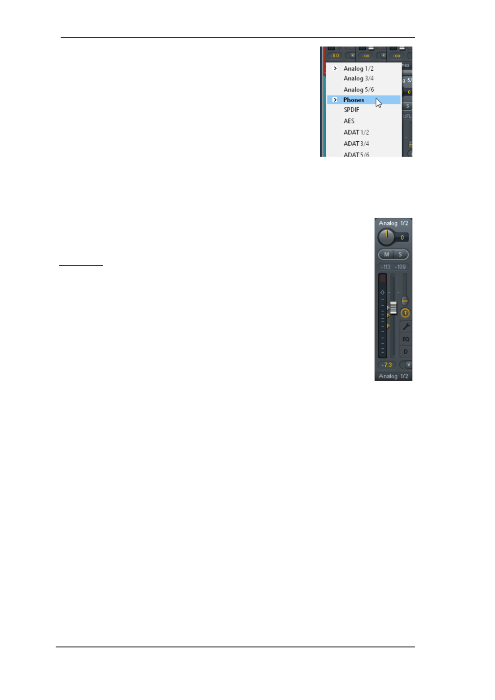
58
User's Guide Fireface UCX II © RME
The lowest field shows the current . A mouse click routing target
opens the routing window to select a routing target. The list shows all
activated routings of the current channel by arrows in front of the
listed entries, the current one is shown in bold letters.
An arrow is only shown with an activated routing. A routing is seen as
activated when audio data is sent. As long as the fader is set to −∞
the current routing will be shown in bold letters, but not have an ar-
row in the front.
Trim Gain. T After a click on the -button one channel’s faders are all synchronized. Instead of
changing only a single routing the fader affects all the channel’s active routings. For a better
overview the faders currently not visible are indicated by orange triangles beside the fader path.
When moving the fader the triangles also move to a new position, equalling the invisible faders ’
new settings.
Note that the fader button is automatically set to the highest routing gain of all rout-
ings so that best control is offered. The gain (fader knob position) of the currently
active routing (the submix selected in the third row) is shown as white triangle.
Background: TotalMix has no fixed channel fader. In case of the Fireface UCX II
there are 20 mono Aux sends, shown alternately as single fader within the channel
strip. The high number of Aux sends enables multiple and fully independent rout-
ings.
In some cases it is necessary to synchronize the gain changes of these routings. An
example is the Post fader function, where a change of the singer’s volume shall be
performed identical to the volume change of the signal sent to the reverb device, so
that the reverb level keeps its relation to the original signal. Another example is the
signal of a guitar that is routed to different submixes, means hardware outputs,
which gets much too loud during the solo part, and therefore needs to be reduced in
volume on all outputs simultaneously. After a click on the Trim button this can be
done easily and with a perfect overview.
As all channel’s routings change simultaneously when Trim is active, this mode basically causes
the same behaviour as a trim pot within the input channel, affecting the signal already before the
mixer. That’s how this function got its name.
In the / the function Trim Gains can be globally switched on and off for all View Options Show
channels. The global Trim mode is recommended when using TotalMix FX as live mixing desk.
The Context Menu. With a right click on the input, playback and output channels their context
menus provide advanced functionality (these menus are also available in the Matrix, but only
directly on the channel labels). The entries are self- planatory and automatically adjust to ex
where the click is performed. On all of these the first entry opens the Channel Layout dialog. The
input channels offer . On a playback Clear, Copy input, paste the input mix and paste its FX
channel are available. On an output channel Copy, Paste and Clear the playback mix Copy and
Mirror functionality for the current submix and of the FX settings is offered.copying

User's Guide Fireface UCX II © RME
59
25.3.1 Settings
A click on the tool symbol opens the channel’s Settings panel with differing elements. For ex-
ample the option Inst exists only in input channel 3-4, and the ADAT channels do not offer the s
phantom power option.
Stereo. Switches the channel to mono or stereo mode.
48V. Activates phantom power at the corresponding input. Serves as
power supply for high quality condenser mics. This option should stay off
with other sources to prevent failure by spikes.
Inst. Switches inputs 3 and 4 individually to Instrument (Hi-Z) mode.
Gain (1- .2) Sets the gain for the four front inputs. The knob can be ad-
justed by dragging the mouse or by the mouse wheel. This also works
when the mouse has been moved over the two gain displays. Then the
gain can be changed separately for left and right channel, even when the
channel is in stereo mode.
Gain (3-8). Additionally to the reference level setting, Line inputs 3 to 8
have an adjustable gain option from 0 dB to +12 dB.
Level. Sets the reference level individually f the Line inputs. The avail-or
able settings are + dBu and +19 dBu. 13
AutoSet. Activates an automatic gain reduction preventing overloads caused by too high gain
settings. See chapter 19.2 for details.
Width. Defines the stereo width. 1.00 equals full stereo, 0.00 mono, -1.00 swapped channels.
FX Send. Setting the level of the signal sent to the FX bus which feeds Echo and Reverb. The
current setting is also visible with closed channel settings, because knob and small fader are
always synchronized. To make this function as useful as possible FX Send is locked to the high-
est submix, thus imitating the function of a standard mixing desk. When moving Aux Post Fader
the big fader both knob and small fader will also move. This way the reverb signal will always
have the same relation to the dry signal.
The level of the signal sent to the effects can be controlled by the level meters of the FX FX In
window. It becomes visible after a click on FX in the View Options.
MS Proc. Activates M/S processing within the stereo channel. Monaural information is sent to
the left channel, stereo information to the right.
Phase L. Inverts the phase of the left channel by 180°.
Phase R. Inverts the phase of the right channel by 180°.
Note: the functions Width, MS Proc, Phase L and Phase R affect all routings of the respective
channel.

60
User's Guide Fireface UCX II
Besides Stereo/Mono, Phase L und Phase R the settings of the Hardware Outputs have r fu ther
options:
Level. Sets the reference levels of the 6 analog Line The avail-outputs.
able settings are +4 dBu, +13 dBu and +19 dBu The Phones (channels .
7-8 have a ) Low (+4 dBu) and High (+19 dBu) setting to choose from.
FX Return. The eect signal (Echo and Reverb) is mixed to the respec-
tive hardware output by the duo knob/small fader.
Talkback. Activates this channel as receiver and output of the Talkback
signal This way Talkback can be sent to any outputs, not only the .
Phones in the Control Room section. Another application could be to
send a certain signal to specic outputs by the push of a button.
No Trim. Sometimes channels need to have a xed routing and level,
which should not be changed in any case. An example is the stereo mix-
down for recording of a live show. With active, the routing to this No Trim
output channel is excluded from the Trim Gains function, therefore is not
changed unintentionally.
Loopback. Sends the output data to the driver as record data. The corresponding submix can
be recorded then. This channel’s hardware input sends its data only to TotalMix, no longer to the
recording software.
Another dierence to the input and playback channels is the button instead of Solo. A click Cue
on Cue sends the respective Hardware Out Out, or any of the Phones put’s audio to the Main
outputs (option in the Control Room section). With this any hardware output can Assign / Cue to
be controlled and listened to through the monitoring output very conveniently.
25.3.2 Equalizer
A click on EQ opens the panel. It is available in all input and output channels, and Equalizer
aects all routings of the respective channel (pre fader). The panel includes a low cut and a 3-
band parametric equa er which can be activated separately. liz
EQ. Activated by the EQ button.
Type. Band 1 and 3 can operate in peak (bell) or shelf
(shelving) mode. The middle band is xed to peak mode.
Band 3 can also operate as (low pass lter), especial-Hi Cut
ly useful for LFE and subwoofer purposes.
Gain. All three bands can change their amplication be-
tween +20 dB to -20 dB.
Freq. The center frequency of the lters is adjustable be-
tween 20 Hz 20 kHz. While in peak mode the center and
frequency is adjusted, in shelf mode the cut-o point (-3 dB)
will be changed.
Q. The Quality factor of the lter is adjustable from 0.7
(wide) to 5.0 (narrow).
Lo Cut. Activated by the button Lo Cut. The slope of the high-pass lter is adjustable between 6,
12, 18 and 24 dB per octave. The cut-o point (-3 dB) is adjustable between 20 Hz and 500 Hz.
Termékspecifikációk
| Márka: | RME |
| Kategória: | hi-fi rendszer |
| Modell: | Fireface UCX II |
Szüksége van segítségre?
Ha segítségre van szüksége RME Fireface UCX II, tegyen fel kérdést alább, és más felhasználók válaszolnak Önnek
Útmutatók hi-fi rendszer RME

16 Augusztus 2024
1 Augusztus 2024
29 Július 2024
28 Július 2024
27 Július 2024
25 Július 2024
25 Július 2024
25 Július 2024
21 Július 2024
21 Július 2024
Útmutatók hi-fi rendszer
- hi-fi rendszer Samsung
- hi-fi rendszer Sony
- hi-fi rendszer Yamaha
- hi-fi rendszer Sharkoon
- hi-fi rendszer Nedis
- hi-fi rendszer LG
- hi-fi rendszer Grundig
- hi-fi rendszer Marantz
- hi-fi rendszer Philips
- hi-fi rendszer Pioneer
- hi-fi rendszer Kärcher
- hi-fi rendszer Olympus
- hi-fi rendszer Oregon Scientific
- hi-fi rendszer SilverCrest
- hi-fi rendszer Garmin
- hi-fi rendszer RCF
- hi-fi rendszer Panasonic
- hi-fi rendszer JVC
- hi-fi rendszer AEG
- hi-fi rendszer Sharp
- hi-fi rendszer Harman Kardon
- hi-fi rendszer Nokia
- hi-fi rendszer Sven
- hi-fi rendszer Oppo
- hi-fi rendszer Hyundai
- hi-fi rendszer Saramonic
- hi-fi rendszer Medion
- hi-fi rendszer Onkyo
- hi-fi rendszer Motorola
- hi-fi rendszer Geemarc
- hi-fi rendszer Vimar
- hi-fi rendszer Technics
- hi-fi rendszer Roland
- hi-fi rendszer JBL
- hi-fi rendszer Camry
- hi-fi rendszer DAP-Audio
- hi-fi rendszer GoGen
- hi-fi rendszer Boss
- hi-fi rendszer Crestron
- hi-fi rendszer Cyrus
- hi-fi rendszer Tripp Lite
- hi-fi rendszer Vivax
- hi-fi rendszer Thomson
- hi-fi rendszer Klipsch
- hi-fi rendszer Technaxx
- hi-fi rendszer Aiwa
- hi-fi rendszer Speco Technologies
- hi-fi rendszer Kenwood
- hi-fi rendszer Rega
- hi-fi rendszer Duronic
- hi-fi rendszer Netgear
- hi-fi rendszer Huawei
- hi-fi rendszer Asus
- hi-fi rendszer Jabra
- hi-fi rendszer Vtech
- hi-fi rendszer Clatronic
- hi-fi rendszer Arturia
- hi-fi rendszer Hama
- hi-fi rendszer PEAQ
- hi-fi rendszer ELAC
- hi-fi rendszer Zoom
- hi-fi rendszer Korg
- hi-fi rendszer Sencor
- hi-fi rendszer GPX
- hi-fi rendszer Focusrite
- hi-fi rendszer Polsen
- hi-fi rendszer Bose
- hi-fi rendszer M-Audio
- hi-fi rendszer AOC
- hi-fi rendszer Lowrance
- hi-fi rendszer Hitachi
- hi-fi rendszer BeamZ
- hi-fi rendszer Continental Edison
- hi-fi rendszer Telefunken
- hi-fi rendszer Nevir
- hi-fi rendszer Sennheiser
- hi-fi rendszer Cambridge
- hi-fi rendszer Monster
- hi-fi rendszer Alpine
- hi-fi rendszer Acoustic Solutions
- hi-fi rendszer Roadstar
- hi-fi rendszer Kiloview
- hi-fi rendszer Omnitronic
- hi-fi rendszer Logitech
- hi-fi rendszer SPL
- hi-fi rendszer Pro-Ject
- hi-fi rendszer TOA
- hi-fi rendszer SVS
- hi-fi rendszer Cobra
- hi-fi rendszer Nextbase
- hi-fi rendszer Scosche
- hi-fi rendszer Crunch
- hi-fi rendszer Sonoro
- hi-fi rendszer Denver
- hi-fi rendszer Dynaudio
- hi-fi rendszer Smart-AVI
- hi-fi rendszer Bush
- hi-fi rendszer Power Dynamics
- hi-fi rendszer Trevi
- hi-fi rendszer Memphis Audio
- hi-fi rendszer Elta
- hi-fi rendszer Audio-Technica
- hi-fi rendszer NGS
- hi-fi rendszer Konig & Meyer
- hi-fi rendszer Daewoo
- hi-fi rendszer Lenoxx
- hi-fi rendszer Dali
- hi-fi rendszer Gembird
- hi-fi rendszer Denon
- hi-fi rendszer ATen
- hi-fi rendszer Muse
- hi-fi rendszer Energy Sistem
- hi-fi rendszer Native Instruments
- hi-fi rendszer OK
- hi-fi rendszer Honor
- hi-fi rendszer Electro-Voice
- hi-fi rendszer JL Audio
- hi-fi rendszer SPC
- hi-fi rendszer Sanus
- hi-fi rendszer Auna
- hi-fi rendszer Mac Audio
- hi-fi rendszer Behringer
- hi-fi rendszer TriStar
- hi-fi rendszer Loewe
- hi-fi rendszer Chord
- hi-fi rendszer Lotronic
- hi-fi rendszer Terratec
- hi-fi rendszer DreamGEAR
- hi-fi rendszer Electro Harmonix
- hi-fi rendszer Shure
- hi-fi rendszer PreSonus
- hi-fi rendszer Steelseries
- hi-fi rendszer Manhattan
- hi-fi rendszer Tannoy
- hi-fi rendszer Plantronics
- hi-fi rendszer Peavey
- hi-fi rendszer Marshall
- hi-fi rendszer Velleman
- hi-fi rendszer Universal Audio
- hi-fi rendszer Morel
- hi-fi rendszer Russound
- hi-fi rendszer Teac
- hi-fi rendszer Clarion
- hi-fi rendszer Scott
- hi-fi rendszer TC Helicon
- hi-fi rendszer Røde
- hi-fi rendszer Monacor
- hi-fi rendszer MXL
- hi-fi rendszer Anthem
- hi-fi rendszer IK Multimedia
- hi-fi rendszer McIntosh
- hi-fi rendszer Sony Ericsson
- hi-fi rendszer ION
- hi-fi rendszer LD Systems
- hi-fi rendszer Jamo
- hi-fi rendszer Blaupunkt
- hi-fi rendszer NAD
- hi-fi rendszer Sagem
- hi-fi rendszer Razer
- hi-fi rendszer Samson
- hi-fi rendszer Logik
- hi-fi rendszer Mackie
- hi-fi rendszer Vonyx
- hi-fi rendszer Alto
- hi-fi rendszer Infinity
- hi-fi rendszer Walrus Audio
- hi-fi rendszer Magnat
- hi-fi rendszer Bang & Olufsen
- hi-fi rendszer AKAI
- hi-fi rendszer Konig
- hi-fi rendszer Marmitek
- hi-fi rendszer TechniSat
- hi-fi rendszer Fenton
- hi-fi rendszer Jensen
- hi-fi rendszer Pyle
- hi-fi rendszer Audioengine
- hi-fi rendszer Rolls
- hi-fi rendszer Salora
- hi-fi rendszer Musical Fidelity
- hi-fi rendszer DataVideo
- hi-fi rendszer Lenco
- hi-fi rendszer Atlona
- hi-fi rendszer Watson
- hi-fi rendszer Schneider
- hi-fi rendszer Audizio
- hi-fi rendszer Brandson
- hi-fi rendszer ECG
- hi-fi rendszer NACON
- hi-fi rendszer Victrola
- hi-fi rendszer Best Buy
- hi-fi rendszer Fender
- hi-fi rendszer Majority
- hi-fi rendszer Rotel
- hi-fi rendszer Bowers & Wilkins
- hi-fi rendszer Franklin
- hi-fi rendszer KEF
- hi-fi rendszer NEC
- hi-fi rendszer Audiolab
- hi-fi rendszer Atlas Sound
- hi-fi rendszer AKG
- hi-fi rendszer AudioControl
- hi-fi rendszer Soundmaster
- hi-fi rendszer Monitor Audio
- hi-fi rendszer Steinberg
- hi-fi rendszer Technical Pro
- hi-fi rendszer Siig
- hi-fi rendszer Rockford Fosgate
- hi-fi rendszer Krüger&Matz
- hi-fi rendszer Dual
- hi-fi rendszer Cardo
- hi-fi rendszer Canton
- hi-fi rendszer WAGAN
- hi-fi rendszer RCA
- hi-fi rendszer Vocopro
- hi-fi rendszer Imperial
- hi-fi rendszer Kicker
- hi-fi rendszer Creative
- hi-fi rendszer DBX
- hi-fi rendszer Sangean
- hi-fi rendszer Topcom
- hi-fi rendszer PowerBass
- hi-fi rendszer Focal
- hi-fi rendszer MB Quart
- hi-fi rendszer IFi Audio
- hi-fi rendszer OneConcept
- hi-fi rendszer ILive
- hi-fi rendszer Auvi
- hi-fi rendszer Tascam
- hi-fi rendszer Homedics
- hi-fi rendszer Arcam
- hi-fi rendszer FiiO
- hi-fi rendszer House Of Marley
- hi-fi rendszer Sound Devices
- hi-fi rendszer Geneva
- hi-fi rendszer Majestic
- hi-fi rendszer Reflexion
- hi-fi rendszer Teufel
- hi-fi rendszer Crosley
- hi-fi rendszer DPA
- hi-fi rendszer REVO
- hi-fi rendszer Advance Acoustic
- hi-fi rendszer MoFi
- hi-fi rendszer CSL
- hi-fi rendszer BSS Audio
- hi-fi rendszer HK Audio
- hi-fi rendszer SWIT
- hi-fi rendszer RGBlink
- hi-fi rendszer KanexPro
- hi-fi rendszer Key Digital
- hi-fi rendszer Glide Gear
- hi-fi rendszer Hosa
- hi-fi rendszer Kramer
- hi-fi rendszer ART
- hi-fi rendszer Music Hall
- hi-fi rendszer Ade
- hi-fi rendszer Altec Lansing
- hi-fi rendszer American Audio
- hi-fi rendszer Audison
- hi-fi rendszer Caliber
- hi-fi rendszer Exibel
- hi-fi rendszer Gemini
- hi-fi rendszer Vision
- hi-fi rendszer Sonos
- hi-fi rendszer Brigmton
- hi-fi rendszer Sunstech
- hi-fi rendszer Sonance
- hi-fi rendszer Swissvoice
- hi-fi rendszer Marquant
- hi-fi rendszer AudioAffairs
- hi-fi rendszer Magnum
- hi-fi rendszer Steren
- hi-fi rendszer Polk
- hi-fi rendszer Audiosonic
- hi-fi rendszer Coby
- hi-fi rendszer Envivo
- hi-fi rendszer Galaxy Audio
- hi-fi rendszer Bigben Interactive
- hi-fi rendszer Pure
- hi-fi rendszer Apogee
- hi-fi rendszer Pyle Pro
- hi-fi rendszer Autotek
- hi-fi rendszer Bigben
- hi-fi rendszer Massive
- hi-fi rendszer IDance
- hi-fi rendszer Laser
- hi-fi rendszer Alba
- hi-fi rendszer Naxa
- hi-fi rendszer QTX
- hi-fi rendszer Boston Acoustics
- hi-fi rendszer Mpman
- hi-fi rendszer Vizio
- hi-fi rendszer Nikkei
- hi-fi rendszer Ematic
- hi-fi rendszer ESI
- hi-fi rendszer Anchor Audio
- hi-fi rendszer Audio Pro
- hi-fi rendszer Superior
- hi-fi rendszer Kunft
- hi-fi rendszer Quantis
- hi-fi rendszer Bluesound
- hi-fi rendszer Irradio
- hi-fi rendszer Karcher Audio
- hi-fi rendszer Cmx
- hi-fi rendszer Revox
- hi-fi rendszer Comica
- hi-fi rendszer Audient
- hi-fi rendszer Paradigm
- hi-fi rendszer Bluetrek
- hi-fi rendszer Starkey
- hi-fi rendszer PAC
- hi-fi rendszer Skytec
- hi-fi rendszer Luxman
- hi-fi rendszer Stereoboomm
- hi-fi rendszer Tivoli Audio
- hi-fi rendszer Senal
- hi-fi rendszer Wolfgang
- hi-fi rendszer Numan
- hi-fi rendszer Iluv
- hi-fi rendszer Ibiza Sound
- hi-fi rendszer Nxg
- hi-fi rendszer Lynx
- hi-fi rendszer Solid State Logic
- hi-fi rendszer HiFi ROSE
- hi-fi rendszer OSD Audio
- hi-fi rendszer Andover
- hi-fi rendszer Mark Levinson
- hi-fi rendszer Auto-T
- hi-fi rendszer Soundstream
- hi-fi rendszer Xoro
- hi-fi rendszer Adastra
- hi-fi rendszer Block
- hi-fi rendszer Avante
- hi-fi rendszer Shokz
- hi-fi rendszer JB Systems
- hi-fi rendszer Orbitsound
- hi-fi rendszer HUMANTECHNIK
- hi-fi rendszer Hercules
- hi-fi rendszer Primare
- hi-fi rendszer Sonifex
- hi-fi rendszer Griffin
- hi-fi rendszer Xantech
- hi-fi rendszer Ferguson
- hi-fi rendszer Eissound
- hi-fi rendszer Extron
- hi-fi rendszer ClearOne
- hi-fi rendszer Ebode
- hi-fi rendszer Werma
- hi-fi rendszer Motu
- hi-fi rendszer Devialet
- hi-fi rendszer Mission
- hi-fi rendszer Teradek
- hi-fi rendszer TCM
- hi-fi rendszer Crown
- hi-fi rendszer Zvox
- hi-fi rendszer Antelope Audio
- hi-fi rendszer CE Labs
- hi-fi rendszer Z CAM
- hi-fi rendszer Avid
- hi-fi rendszer Icon
- hi-fi rendszer Mtx Audio
- hi-fi rendszer General Electric
- hi-fi rendszer Aquatic AV
- hi-fi rendszer Parasound
- hi-fi rendszer Promate
- hi-fi rendszer SoundCast
- hi-fi rendszer Hollyland
- hi-fi rendszer Boytone
- hi-fi rendszer Astell&Kern
- hi-fi rendszer TV One
- hi-fi rendszer Maretron
- hi-fi rendszer Xact
- hi-fi rendszer Ruark Audio
- hi-fi rendszer Magnavox
- hi-fi rendszer Esoteric
- hi-fi rendszer ANT
- hi-fi rendszer Leviton
- hi-fi rendszer Rane
- hi-fi rendszer ESX
- hi-fi rendszer NUVO
- hi-fi rendszer JK Audio
- hi-fi rendszer Lexicon
- hi-fi rendszer Fluance
- hi-fi rendszer Altra
- hi-fi rendszer On-Q
- hi-fi rendszer Vantage Point
- hi-fi rendszer Planet Audio
- hi-fi rendszer Fluid
- hi-fi rendszer IFi
- hi-fi rendszer Goodis
- hi-fi rendszer E-bench
- hi-fi rendszer Roon
- hi-fi rendszer Voco
- hi-fi rendszer Linear
- hi-fi rendszer SSV Works
- hi-fi rendszer DAP
- hi-fi rendszer Vankyo
- hi-fi rendszer Glorious
- hi-fi rendszer CAD Audio
- hi-fi rendszer The Box
- hi-fi rendszer AmpliVox
- hi-fi rendszer Audiofrog
- hi-fi rendszer WyreStorm
- hi-fi rendszer Accsoon
- hi-fi rendszer Juke Audio
- hi-fi rendszer Meridian
- hi-fi rendszer DiGiGrid
- hi-fi rendszer CLXmusic
- hi-fi rendszer Nuheara
- hi-fi rendszer Metric Halo
- hi-fi rendszer Universal Remote Control
- hi-fi rendszer Prism Sound
- hi-fi rendszer Antelope
- hi-fi rendszer Switchcraft
- hi-fi rendszer Digigram
- hi-fi rendszer Defender
- hi-fi rendszer Titanwolf
- hi-fi rendszer Liam&Daan
- hi-fi rendszer Aplic
- hi-fi rendszer Crystal Video
- hi-fi rendszer Atoll
- hi-fi rendszer Bennett & Ross
- hi-fi rendszer INKEE
- hi-fi rendszer Vaxis
Legújabb útmutatók hi-fi rendszer

9 Április 2025

6 Április 2025
2 Április 2025
1 Április 2025
31 Március 2025
29 Március 2025
29 Március 2025
29 Március 2025
29 Március 2025
29 Március 2025