Használati útmutató MSI MEG Z590 UNIFY-X
Olvassa el alább 📖 a magyar nyelvű használati útmutatót MSI MEG Z590 UNIFY-X (74 oldal) a lencse kategóriában. Ezt az útmutatót 5 ember találta hasznosnak és 2 felhasználó értékelte átlagosan 4.5 csillagra
Oldal 1/74

1
Quick Start
Quick Start
Thank you for purchasing the MSI® motherboard. This Quick Start MEG Z590 UNIFY-X
section provides demonstration diagrams about how to install your computer. Some
of the installations also provide video demonstrations. Please link to the URL to watch
it with the web browser on your phone or tablet. You may have even link to the URL by
scanning the QR code.
Preparing Tools and Components
Intel® LGA1200 CPU
CPU Fan
DDR4 Memory
Graphics Card
SATA Hard Disk Drive
SATA DVD Drive
Phillips Screwdriver
Chassis
Power Supply Unit
A Package of Screws
Thermal Paste

2Quick Start
Safety Information
∙The components included in this package are prone to damage from electrostatic
discharge (ESD). Please adhere to the following instructions to ensure successful
computer assembly.
∙Ensure that all components are securely connected. Loose connections may cause
the computer to not recognize a component or fail to start.
∙Hold the motherboard by the edges to avoid touching sensitive components.
∙It is recommended to wear an electrostatic discharge (ESD) wrist strap when
handling the motherboard to prevent electrostatic damage. If an ESD wrist strap is
not available, discharge yourself of static electricity by touching another metal object
before handling the motherboard.
∙Store the motherboard in an electrostatic shielding container or on an anti-static
pad whenever the motherboard is not installed.
∙Before turning on the computer, ensure that there are no loose screws or metal
components on the motherboard or anywhere within the computer case.
∙Do not boot the computer before installation is completed. This could cause
permanent damage to the components as well as injury to the user.
∙If you need help during any installation step, please consult a certified computer
technician.
∙Always turn off the power supply and unplug the power cord from the power outlet
before installing or removing any computer component.
∙Keep this user guide for future reference.
∙Keep this motherboard away from humidity.
∙Make sure that your electrical outlet provides the same voltage as is indicated on
the PSU, before connecting the PSU to the electrical outlet.
∙Place the power cord such a way that people can not step on it. Do not place
anything over the power cord.
∙All cautions and warnings on the motherboard should be noted.
∙If any of the following situations arises, get the motherboard checked by service
personnel:
▪Liquid has penetrated into the computer.
▪The motherboard has been exposed to moisture.
▪The motherboard does not work well or you can not get it work according to user
guide.
▪The motherboard has been dropped and damaged.
▪The motherboard has obvious sign of breakage.
∙Do not leave this motherboard in an environment above 60°C (140°F), it may damage
the motherboard.

3
Quick Start
Case stand-off notification
Before installing the motherboard into the case, install first the necessary mounting
stand-off required for a motherboard on the mounting plate in the case.
To prevent damage to the motherboard, any unnecessary mounting stand-off between
the motherboard circuits and the computer case is prohibited. The Case standoff keep
out zone signs will be marked on the backside of motherboard (as shown below) to
serve as a warning to user.
4Quick Start
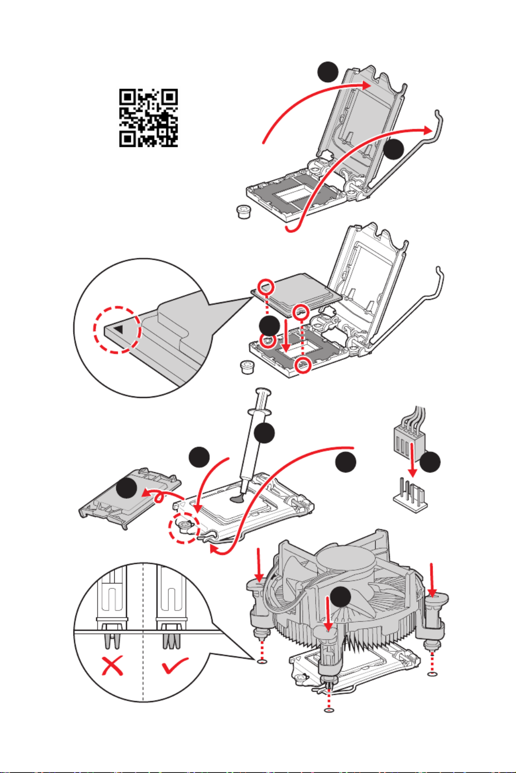
Installing a Processor
⚽
https://youtu.be/4ce91YC3Oww
1
2
3
6
45
7
8
9

5
Quick Start
Installing DDR4 memory
http://youtu.be/T03aDrJPyQs
⚽
DIMMB1 DIMMA1
DIMMB1

6Quick Start
HDD LED
RESET SW
Connecting the Front Panel Header
http://youtu.be/DPELIdVNZUI
JFP1
HDD LED HDD LED -
HDD LED +
POWER LED -
POWER LED +
POWER LED
1
2 10
9
++
+- --
-
+
Power LED
HDD LED Reset Switch
Reserved
Power Switch
JFP1
1 HDD LED + 2 Power LED +
3 HDD LED - 4 Power LED -
5 Reset Switch 6 Power Switch
7 Reset Switch 8 Power Switch
9 Reserved 10 No Pin
RESET SW
POWER SW
POWER LED+
POWER LED-
HDD LED
⚽

7
Quick Start
Installing the Motherboard
1
2
https://youtu.be/wWI6Qt51Wnc
⚽
Torque:
3 kgf·cm*
*3 kgf·cm
= 0.3 N·m
= 2.6 lbf·in

8Quick Start
Connecting the Power Connectors
http://youtu.be/gkDYyR_83I4
ATX_PWR1
CPU_PWR1 PCIE_PWR1
⚽
CPU_PWR2

9
Quick Start
Installing SATA Drives
http://youtu.be/RZsMpqxythc
1
23
4
5
⚽

10 Quick Start
1
Installing a Graphics Card
http://youtu.be/mG0GZpr9w_A
2
3
4
5
6
⚽
11
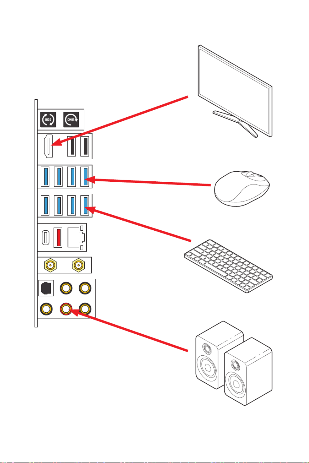
Quick Start
Connecting Peripheral Devices

12 Quick Start
Power On
4
3
12

13
Contents
Contents
Quick Start ............................................................................................................. 1
Preparing Tools and Components.......................................................................... 1
Safety Information 2 ..................................................................................................
Case stand-off notification 3 .....................................................................................
Installing a Processor 4 ............................................................................................
Installing DDR4 memory 5 ........................................................................................
Connecting the Front Panel Header 6 ......................................................................
Installing the Motherboard 7 .....................................................................................
Connecting the Power Connectors 8 ........................................................................
Installing SATA Drives 9 ............................................................................................
Installing a Graphics Card 10 ....................................................................................
Connecting Peripheral Devices 11 ............................................................................
Power On 12 ..............................................................................................................
Specifications 16 .......................................................................................................
JCORSAIR1 Connector Specification 23 ....................................................................
Package contents ................................................................................................ 24
Block Diagram .................................................................................................... 25
Rear I/O Panel ..................................................................................................... 26
LAN Port LED Status Table 26 ..................................................................................
Audio Ports Configuration 26 ....................................................................................
Realtek Audio Console 27 .........................................................................................
Installing Antennas 29 ...............................................................................................
Overview of Components ....................................................................................30
CPU Socket 32 ...........................................................................................................
DIMM Slots 33 ............................................................................................................
PCI_E1~4: PCIe Expansion Slots 34 ..........................................................................
M2_1~4: M.2 Slots (Key M) 36 ...................................................................................
SATA1~6: SATA 6Gb/s Connectors 38 .......................................................................
JFP1, JFP2: Front Panel Connectors 39 ...................................................................
JAUD1: Front Audio Connector 39 ............................................................................
CPU_PWR1~2, ATX_PWR1, PCIE_PWR1: Power Connectors 40 .............................
JSLOW1: Slow Mode Booting Jumper 41 ..................................................................
JLN1~2: Low Temperature Booting Jumper 41 .......................................................
JOC_FS1: Safe Boot Jumper 42 ................................................................................
JOC_RT1: OC Retry Jumper 42 .................................................................................
JTBT1: Thunderbolt Add-on Card Connector 42 ......................................................

14 Contents
V-Check Points Lite 43 ..............................................................................................
T_SEN1: Thermal Sensor Connectors 43 .................................................................
JDASH1 : Tuning Controller connector 44 ................................................................
JUSB4: USB 3.2 Gen 2 Type-C Connector 46 ............................................................
JUSB3: USB 3.2 Gen 1 Connector 46 ........................................................................
JUSB1~2: USB 2.0 Connectors 47 .............................................................................
JTPM1: TPM Module Connector 47 ...........................................................................
CPU_FAN1, PUMP_FAN1, SYS_FAN1~6: Fan Connectors 48 ..................................
JCI1: Chassis Intrusion Connector 49 .......................................................................
POWER1, RESET1: Power Button, Reset Button 49 .................................................
JBAT1: Clear CMOS (Reset BIOS) Jumper 50 ...........................................................
BIOS_SW1: Multi-BIOS Switch 50 .............................................................................
JRGB1: RGB LED connector 51 .................................................................................
JRAINBOW1~2: Addressable RGB LED connectors 52 ............................................
JCORSAIR1: CORSAIR Connector 53 ........................................................................
Onboard LEDs ...................................................................................................... 54
EZ Debug LED 54 .......................................................................................................
XMP LED 54 ...............................................................................................................
Debug Code LED 54 ...................................................................................................
Hexadecimal Character Table 55 ..............................................................................
Boot Phases 55 ..........................................................................................................
Debug Code LED Table 55 .........................................................................................
ACPI States Codes 59 ................................................................................................
CPU Temperature 59 .................................................................................................
Installing OS, Drivers & MSI Center .................................................................... 60
Installing Windows® 10 60 .........................................................................................
Installing Drivers 60 ..................................................................................................
MSI Center 60 ............................................................................................................
UEFI BIOS ............................................................................................................. 61
BIOS Setup 62 ............................................................................................................
Entering BIOS Setup 62 .............................................................................................
BIOS User Guide 62 ...................................................................................................
Resetting BIOS 63 ......................................................................................................
Updating BIOS 63 .......................................................................................................
Nahimic 3 ............................................................................................................. 65
Installation and Update 65 ........................................................................................
Audio Tab 65 ..............................................................................................................
Microphone Tab 66 ....................................................................................................

15
Contents
Sound Tracker Tab 67 ...............................................................................................
Settings Tab 67 ..........................................................................................................
RAID Configuration .............................................................................................. 68
Intel® Optane™ Memory Configuration .............................................................. 69
Troubleshooting 70 .................................................................................................

16 Specifications
Specifications
CPU
∙Supports 10th Gen Intel® Core ™ Processors, 11th Gen
Intel® Core ™ Processors, Pentium® Gold and Celeron®
Processors*
∙Processor socket LGA1200
* Please go to intel.com for compatibility information
Chipset Intel® Z590 Chipset
Memory
∙2x DDR4 memory slots, support up to 64GB*
∙Supports 1R 2133/ 2666/ 2933 MHz for 10th Gen Intel®
CPU (by JEDEC & POR)*
∙Supports 1R 2133/ 2666/ 2933/ 3200 MHz for 11th Gen
Intel® CPU (by JEDEC & POR)*
∙Max overclocking frequency:
▪1DPC 1R Max speed up to 5600 MHz
▪1DPC 2R Max speed up to 4800+ MHz
∙Supports Dual-Channel mode
∙Supports non-ECC mode, un-buffered memory
∙Supports Intel® Extreme Memory Profile (XMP)
* Please refer www.msi.com for more information on compatible memory.
Expansion Slot
∙1x PCIe x16 slot (PCI_E2, from CPU)
▪Supports up to PCIe 4.0 x16 with11th Gen CPU*
▪Supports up to PCIe 3.0 x16 with10th Gen CPU*
∙1x PCIe 3.0 p16-x4 slot (PCI_E4, from Z590 chipset)**
∙2x PCIe 3.0 p16-x1 slots (from Z590 chipset)
* PCI_E2 will only support p16-x8 speed, when M2_2 and M2_3 are from CPU by BIOS
selection.
** PCI_E4 and M2_4 share the same bandwidth, if you want to use both of them
simultaneously, the PCI_E4 will only support p16-x1 speed and the M2_4 will only
support p16-x2 speed. But if you want to install and enable the in graphics card
PCI_E4 slot, the M2_4 slot should be empty.
Multi-GPU ∙Supports 2-Way AMD® CrossFire™ Technology
Onboard Graphics
∙1x HDMI 2.0b with HDR port, supports a maximum
resolution of 4K 60Hz */**
* Available for the processor with integrated graphics.
** Graphics specifications may vary depending on the CPU installed.
Continued on next page

17
Specifications
Continued from previous page
Storage
∙6x SATA 6Gb/s ports (from Z590 chipset)
∙4x M.2 slots (Key M)
▪M2_1 (from CPU)
▫Available only on 11th Gen Intel® CPU
▫Supports up to PCIe 4.0 x4
▫Supports 2242/ 2260/ 2280/ 22110 storage devices
▪M2_2* & M2_3** slots
▫Support up to PCIe 3.0 p17-x4 and SATA 6Gb/s (from
Z590 chipset, default)***
▫Support up to PCIe 4.0 p17-x4 (from CPU, by BIOS
selection), it is available only on 11th Gen Intel® CPU
▫M2_2 supports 2242/ 2260/ 2280 storage devices
▫M2_3 supports 2242/ 2260/ 2280/ 22110 storage
devices
▪M2_4 slot (from Z590 chipset)***/ ****
▫Supports up to PCIe 3.0 x4, 2242/ 2260/ 2280 storage
devices
∙ Supports Intel® Smart Response Technology for Intel®
Core™ processors
* SATA2 will be unavailable when installing M.2 SATA SSD in the M2_2 slot.
** SATA5 & SATA6 will be unavailable when installing M.2 SATA/ PCIe SSD in
the M2_3 slot.
*** Intel® Optane™ Memory Ready. Before using Intel® Optane™ memory
modules, please ensure that you have updated the drivers and BIOS to the latest
version from MSI website.
**** PCI_E4 and M2_4 share the same bandwidth, if you want to use both of
them simultaneously, the PCI_E4 will only support p17-x1 speed and the M2_4 will
only support p17-x2 speed. But if you want to install and enable the in graphics card
PCI_E4 slot, the M2_4 slot should be empty.
RAID
∙Supports RAID 0, RAID 1, RAID 5 and RAID 10 for SATA
storage devices
∙Supports RAID 0 and RAID 1 for M.2 NVMe storage devices
Continued on next page

18 Specifications
Continued from previous page
USB
∙Intel® Z590 Chipset
▪1x USB 3.2 Gen 2x2 20Gbps Type-C port on the back
panel
▪2x USB 3.2 Gen 2 10Gbps ports (1 Type-A port on the
back panel and 1 Type-C internal connector)
▪10x USB 3.2 Gen 1 5Gbps ports (8 Type-A ports on the
back panel, 2 ports are available through internal USB
3.2 Gen 1 connector)
▪2x USB 2.0 ports on the back panel
∙Hub-GL850G
▪4x USB 2.0 ports through internal USB 2.0 connectors
Audio
Realtek® ALC4080 Codec
∙7.1-Channel High Definition Audio
∙Supports S/PDIF output
LAN 1x Intel® I225-V 2.5Gbps LAN controller
Wireless LAN &
Bluetooth®
Intel® WiFi 6E AX210
∙The Wireless module is pre-installed in the M.2 (Key-E)
slot
∙Supports MU-MIMO TX/RX, 2.4GHz/ 5GHz/ 6GHz*
(160MHz) up to 2.4Gbps
∙Supports 802.11a/ b/ g/ n/ ac/ ax
∙Supports Bluetooth® 5.2**, FIPS, FISMA
* Wi-Fi 6E 6GHz may depend on every country’s regulations and will be ready in
WIN10 21H1.
** Bluetooth 5.2 will be ready in WIN10 21H1.
Continued on next page

19
Specifications
Continued from previous page
Internal Connectors
·1x 24-pin ATX main power connector
·2x 8-pin ATX 12V power connectors
·1x 6-pin ATX PCIE power connector
·6x SATA 6Gb/s connectors
·4x M.2 slots (M-Key)
·1x USB 3.2 Gen 2 10Gbps Type-C port
·1x USB 3.2 Gen 1 5Gbps connector (supports additional 2
USB 3.2 Gen 1 5Gbps ports)
·2x USB 2.0 connectors (supports additional 4 USB 2.0
ports)
·1x 4-pin CPU fan connector
·1x 4-pin water-pump fan connector
·6x 4-pin system fan connectors
·1x Front panel audio connector
·2x System panel connectors
·1x Chassis Intrusion connector
·1x 2-pin Thermal Sensors connector
·1xTPM module connector
·1x Tuning Controller connector
·1x TBT connector (Supports RTD3)
Jumper
·1x Slow mode jumper
·2x Low Temperature Booting jumpers
·1x Clear CMOS jumper
·1x Safe boot jumper
·1x OC Retry jumper
LED Features
·1x 2-Digit Debug Code LED
·4x EZ Debug LED
·1x 4-pin RGB LED connector
·2x 3-pin RAINBOW LED connectors
·1x 3-pin CORSAIR LED connector
Internal Buttons ·1x Power button
·1x Reset button
Switches ·1x Multi-BIOS switch
Continued on next page

20 Specifications
Continued from previous page
Back Panel
Connectors
∙1x Clear CMOS button
∙1x Flash BIOS button
∙2x USB 2.0 Type-A ports
∙1x HDMI port
∙8 x USB 3.2 Gen 1 5Gbps Type-A ports
∙1 x LAN (RJ45) port
∙1 x USB 3.2 Gen 2 10Gbps Type-A ports
∙1 x USB 3.2 Gen 2x2 20Gbps Type-C ports
∙2 x Wi-Fi Antenna connectors
∙5 x OFC audio jacks
∙1 x Optical S/PDIF Out connector
I/O Controller NUVOTON NCT6687D-M Controller Chip
Hardware Monitor
∙CPU/ System/ Chipset temperature detection
∙CPU/ System/ Pump fan speed detection
∙CPU/ System/ Pump fan speed control
Form Factor ∙ATX Form Factor
∙12 in. x 9.6 in. (30.5 cm x 24.4 cm)
BIOS Features
∙Dual BIOS
∙2x 256 Mb flash
∙UEFI AMI BIOS
∙ACPI 6.2, SMBIOS 3.0
∙Multi-language
Continued on next page

21
Specifications
Continued from previous page
Software
·Drivers
·MSI Center
·Intel® Extreme Tuning Utility
·Nahimic
·MSI APP Player (BlueStacks)
·Open Broadcaster Software (OBS)
·CPU-Z MSI GAMING
·Google Chrome™, Google Toolbar, Google Drive
·Norton™ Internet Security Solution
MSI Center
Features
·Duet Display
·MSI Sound Tune
·Gaming Mode
·Creator Mode
·Game Highlights
·LAN Manager
·Mystic Light
·Ambient Link
·Frozr AI Cooling
·User Scenario
·True Color
·Live Update
·Monitor
·Super Charger
·Speed Up
Continued on next page

22 Specifications
Continued from previous page
Special Features
∙Audio
▪Audio Boost 5
▪Nahimic 3
▪Sound Tune
∙Network
▪2.5G LAN
▪LAN Manager
▪Intel WiFi
∙Cooling
▪All Aluminum Design
▪Extended Heatsink Design
▪MOSFET Baseplate
▪M.2 Shield Frozr
▪K7 thermal pad
▪Choke pad
▪Pump Fan
▪Smart Fan Control
∙LED
▪Mystic Light Extension (RAINBOW/CORSAIR/RGB)
▪Mystic Light SYNC
▪Ambient Link
▪EZ LED Control
▪EZ DEBUG LED
∙Protection
▪PCI-E Steel Armor
▪Pre-installed I/O Shielding
Continued on next page

23
Specifications
Continued from previous page
Special Features
∙Performance
▪Lightning Gen 4 PCI-E Slot
▪Lightning Gen 4 M.2
▪DDR4 Boost
▪Memory Force
▪Core Boost
▪Game Boost
▪OC Engine
▪Lightning USB 20G
▪USB 3.2 Gen 2 10G
▪USB with Type A+C
▪Front USB Type-C
▪Dual CPU Power 2x 8 pin
▪SUPPLEMENTAL PCIE POWER CONNECTOR
▪2oz Copper thickened PCB
∙Experience
▪Smart Button
▪MSI Center
▪Duet Display
▪Frozr AI Cooling
▪Click BIOS 5
▪System Saver
▪Flash BIOS Button
JCORSAIR1 Connector Specification
Supporting CORSAIR RGB Products Maximum connection
Lighting Node PRO LED Strip
20*
* 20% brightness is recommended when the number of
LED strips exceeds 8.
HD120 RGB Fan 6
SP120 RGB Fan 6
LL120 RGB Fan 6

24 Package contents
Package contents
Please check the contents of your motherboard package. It should contain:
Motherboard MEG Z590 UNIFY-X
Documentation User manual 1
Quick installation guide 1
Application USB drive with drivers & utilities 1
Cables
SATA 6Gb/s cables 2
LED JRGB Y cable 1
LED JCORSAIR cable 1
LED JRAINBOW cable 1
Tuning controller cable 1
Accessories
Wi-Fi antenna 1
Tuning controller module 1
Case badge 1
M.2 screw + standoff (2 sets/pack) 2
MEG sticker 1
SATA cable stickers 1
Product registration card 1
Gifts Small screwdriver set 1
Small brush 1
⚠
Important
If any of the above items are damaged or missing, please contact your retailer.

25
Block Diagram
Block Diagram
CPU
PCH
PCI_E2
DDR4 2Channel
DIMM A1
DIMM B1
DMI
PCI_E1 & PCI_E3
WiFi AX210
Intel LAN 2.5G
HD Audio
ALC4080
M2_1
PCI_E4
M2_4
M2_2
M2_3
SATA5/6
SATA2
SIO 6687
TPM
SPI
MCU
USB 3.2 Gen 2x2 20Gbps
USB 3.2 Gen 2 10Gbps
USB 3.2 Gen 1 5Gbps
USB 2.0
USB 2.0
Hub-GL850G
SATA1/3/4
Switch

26 Rear I/O Panel
Rear I/O Panel
∙Clear CMOS button - Power off your computer. Press and hold the Clear CMOS
button for about 5-10 seconds to reset BIOS to default values.
∙Flash BIOS Port/ Button - Please refer to page 62 for Updating BIOS with Flash BIOS
Button.
LAN Port LED Status Table
Audio Ports Configuration
Audio Ports
Channel
2468
Center/ Sub-woofer Out ● ●
Rear Speaker Out ●●●
Line-In/ Side Speaker Out ●
Line-Out/ Front Speaker Out ●●●●
Mic In
(●: connected, Blank: empty)
USB 3.2 Gen 2
10Gbps Type-A
USB 3.2 Gen 2x2
20Gbps Type-C
USB 3.2 Gen 1
5Gbps Type-A
2.5 Gbps LAN
Audio Ports
Optical
S/PDIF-Out
Clear CMOS
button
Wi-Fi Antenna
connectors
USB 2.0
Flash BIOS
Button
Link/ Activity LED
Status Description
Off No link
Yellow Linked
Blinking Data activity
Speed LED
Status Description
Off 10 Mbps connection
Green 100/1000 Mbps connection
Orange 2.5 Gbps connection
Flash BIOS Port

27
Rear I/O Panel
Realtek Audio Console
After Realtek Audio Console is installed. You can use it to change sound settings to get
better sound experience.
∙Device Selection - allows you to select a audio output source to change the related
options. The sign indicates the devices as default.check
∙Application Enhancement - the array of options will provide you a complete
guidance of anticipated sound effect for both output and input device.
∙Main Volume - controls the volume or balance the right/left side of the speakers
that you plugged in front or rear panel by adjust the bar.
∙Jack Status - depicts all render and capture devices currently connected with your
computer.
∙Connector Settings - configures the connection settings.
Auto popup dialog
When you plug into a device at an audio jack, a dialogue window will pop up asking you
which device is current connected.
Each jack corresponds to its default setting as shown on the next page.
⚠
Important
The pictures above for reference only and may vary from the product you purchased.
Jack Status
Connector Settings
Device
Selection
Main Volume
Application Enhancement

28 Rear I/O Panel
Audio jacks to headphone and microphone diagram
Audio jacks to stereo speakers diagram
Audio jacks to 7.1-channel speakers diagram
AUDIO INPUT
AUDIO INPUT
Rear Front
Side Center/
Subwoofer

29
Rear I/O Panel
Installing Antennas
1. Combine the antenna with the base.
2. Screw two antenna cables tight to the WiFi antenna connectors as shown.
1
2
3. Place the antenna as high as possible.

30 Overview of Components
Overview of Components
RESET1
SYS_FAN6
JTPM1
JFP2
JBAT1
JFP1
JRAINBOW2
JRGB1
SATA▼1▲2
JUSB4
JUSB3
SATA▼3▲4
SATA▼5▲6
M2_1
M2_2 M2_3
PUMP_FAN1
CPU_FAN1
SYS_FAN5
PCI_E1
PCI_E2
JOC_RT1SYS_FAN1
JSLOW1
JOC_FS1
JCI1
JLN1
JSMB1
JLN2
PCI_E3
PCI_E4
M2_4
JDASH1
JTBT1
JUSB1
CPU Socket
CPU_PWR1
CPU_PWR2
JCORSAIR1
POWER1
PCIE_PWR1
JAUD1
BIOS_SW1
JRAINBOW1
SYS_FAN4
SYS_FAN3
SYS_FAN2
ATX_PWR1
T_SEN1
DIMMA1
DIMMB1
JUSB2

31
Overview of Components
Component Contents
Port Name Port Type Page
BIOS_SW1 Multi-BIOS Switch 50
CPU_FAN1, PUMP_FAN1,
SYS_FAN1~6 Fan Connectors 48
CPU_PWR1~2, ATX_PWR1,
PCIE_PWR1 Power Connectors 40
CPU Socket LGA 1200 32
DIMMA1, DIMMB1 DIMM Slots 33
JAUD1 Front Audio Connector 39
JBAT1 Clear CMOS Jumper 50
JCI1 Chassis Intrusion Connector 49
JCORSAIR1 CORSAIR Connector 53
JDASH1 Tuning Controller connector 44
JFP1, JFP2 Front Panel Connectors 39
JLN1~2 Low Temperature Booting Jumper 41
JOC_FS1 Safe Boot Jumper 42
JOC_RT1 OC Retry Jumper 42
JRAINBOW1~2 Addressable RGB LED connectors 52
JRGB1 RGB LED connector 51
JSLOW1 Slow Mode Booting Jumper 41
JTBT1 Thunderbolt Add-on Card Connector 42
JTPM1 TPM Module Connector 47
JUSB1~2 USB 2.0 Connectors 47
JUSB3 USB 3.2 Gen 1 Connector 46
JUSB4 USB 3.2 Gen 2 Type-C Connector 46
M2_1~4 M.2 Slots (Key M) 36
PCI_E1~4 PCIe Expansion Slots 34
POWER1, RESET1 Power Button, Reset Button 49
SATA1~6 SATA 6Gb/s Connectors 38
T_SEN1 Thermal Sensor Connectors 43

32 Overview of Components
⚠
Important
∙
Always unplug the power cord from the power outlet before installing or removing
the CPU.
∙
Please retain the CPU protective cap after installing the processor. MSI will deal
with Return Merchandise Authorization (RMA) requests if only the motherboard comes
with the protective cap on the CPU socket.
∙
When installing a CPU, always remember to install a CPU heatsink. A CPU heatsink
is necessary to prevent overheating and maintain system stability.
∙
Confirm that the CPU heatsink has formed a tight seal with the CPU before booting
your system.
∙
Overheating can seriously damage the CPU and motherboard. Always make sure
the cooling fans work properly to protect the CPU from overheating. Be sure to apply
an even layer of thermal paste (or thermal tape) between the CPU and the heatsink to
enhance heat dissipation.
∙
Whenever the CPU is not installed, always protect the CPU socket pins by covering
the socket with the plastic cap.
∙
If you purchased a separate CPU and heatsink/ cooler, Please refer to the
documentation in the heatsink/ cooler package for more details about installation.
∙
This motherboard is designed to support overclocking. Before attempting to
overclock, please make sure that all other system components can tolerate
overclocking. Any attempt to operate beyond product specifications is not
recommended. MSI® does not guarantee the damages or risks caused by inadequate
operation beyond product specifications.
CPU Socket
Introduction to the LGA 1200 CPU
The surface of the LGA 1200 CPU has
two and a to notches golden triangle
assist in correctly lining up the CPU for
motherboard placement. The golden
triangle is the Pin 1 indicator.
50.77 mm
Distance from the center of the
CPU to the nearest DIMM slot.

33
Overview of Components
DIMM Slots
DIMMA1 DIMMB1
Channel A Channel B
Memory module installation recommendation
⚠
Important
∙
Always insert memory modules in the slot first.DIMMB1
∙
To ensure system stability for Dual channel mode, memory modules must be of the
same type, number and density.
∙
Some memory modules may operate at a lower frequency than the marked value
when overclocking due to the memory frequency operates dependent on its Serial
Presence Detect (SPD). Go to BIOS and find the to set the memory DRAM Frequency
frequency if you want to operate the memory at the marked or at a higher frequency.
∙
It is recommended to use a more efficient memory cooling system for full DIMMs
installation or overclocking.
∙
The stability and compatibility of installed memory module depend on installed CPU
and devices when overclocking.
∙
Please refer www.msi.com for more information on compatible memory.
DIMMB1
DIMMB1 DIMMA1

34 Overview of Components
PCI_E1~4: PCIe Expansion Slots
PCI_E1: PCIe 3.0 p34-x1 (From Z590 chipset)
PCI_E2: PCIe 4.0 x16 (From CPU)
PCI_E4: PCIe 3.0 p34-x4 (From Z590 chipset)
PCI_E3: PCIe 3.0 p34-x1 (From Z590 chipset)
⚠
Important
∙
If you install a large and heavy graphics card, you need to use a tool such as MSI
Gaming Series Graphics Card Bolster to support its weight to prevent deformation of
the slot.
∙
For a single PCIe x16 expansion card installation with optimum performance, using
the slot is recommended.PCI_E2
∙
When adding or removing expansion cards, always turn off the power supply and
unplug the power supply power cable from the power outlet. Read the expansion
card’s documentation to check for any necessary additional hardware or software
changes.
∙
PCI_E2 will only support x8 speed, when M2_2 and M2_3 are from CPU.
∙
PCI_E4 and M2_4 share the same bandwidth, if you want to use both of them
simultaneously, the PCI_E4 will only support p34-x1 speed and the M2_4 will only support
x2 speed. But if you want to install and enable the graphics card in PCI_E4 slot, the
M2_4 slot should be empty.

35
Overview of Components
PCIe bandwidth configuration table for PCIe & M.2 slots
The M2_2 and M2_3 slots can be used under two PCIe bandwidth modes: Chipset
mode (default) and CPU mode (by BIOS setting). Please refer the PCIe bandwidth
configuration table below for details.
Slot Chipset mode (Default) CPU mode (By BIOS setting)
PCI_E1 3.0 x1 3.0 x1
PCI_E2 4.0* x16 or 3.0 x16 4.0* p35-x8 or 3.0 x8
PCI_E3 3.0 x1 3.0 x1
PCI_E4 — 3.0 x4 3.0 x1 — 3.0 x4 3.0 x1
M2_1 4.0 x4
(M2_1 slot is available only on 11th Gen Intel® CPU)
M2_2 3.0 x4 4.0* p35-x4 or 3.0 x4
M2_3 3.0 x4 4.0* p35-x4 or 3.0 x4
M2_4 3.0 x4 — 3.0 x2 3.0 x4 — 3.0 x2
(─: unavailable)
* PCIe 4.0 specification is available only on 11th Gen Intel® CPU.
⚠
Important
Enabling CPU mode BIOS > SETTINGS > Advanced for M2_2 & M2_3 slots, please go to
> PCIe/PCI sub-system Settings > CPU PCIe Lanes Configuration and configure the
PCIe Lanes to for PCI_E2, M2_2 and M2_3 slots first. In , the x8/x4/x4 CPU mode
PCI_E2, M2_2 and M2_3 slots share the same PCIe bandwidth.
36 Overview of Components
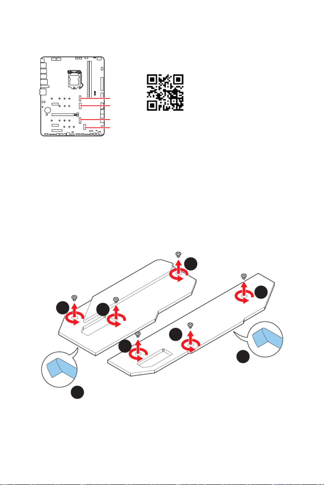
M2_1~4: M.2 Slots (Key M)
Installing M.2 module
1. Loosen the screws of M.2 SHIELD FROZR heatsink.
2. Remove the M.2 SHIELD FROZR and remove the protective films from the thermal
pads of heatsink.
2
2
11
1
1
1
1
M2_1
M2_2
M2_3
M2_4
⚠
Important
∙
Intel® RST only supports PCIe M.2 SSD with UEFI ROM.
∙
Intel® Optane™ Memory Ready for M2_2 (from chipset), M2_3 (from chipset) and
M2_4 slot.
⚽
Video Demonstration
Watch the video to learn how to
Install M.2 SSD.
https://youtu.be/2UeWMgjwogU
M2_1 & M2_2
M2_3 & M2_4
37
Overview of Components
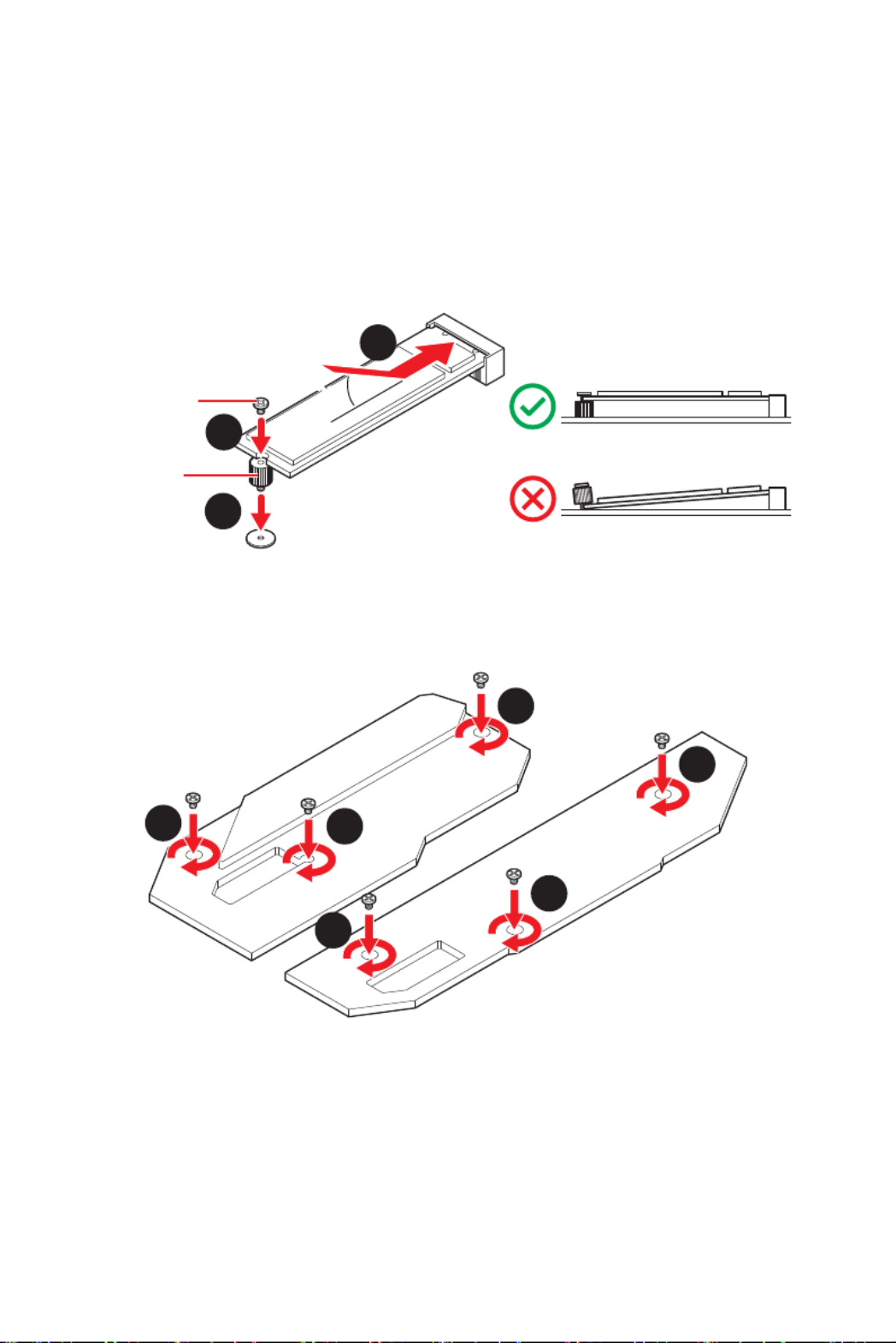
3. Secure the supplied M.2 standoff according to your M.2 SSD length if need.
4. Insert your M.2 SSD into the M.2 slot at a 30-degree angle.
5. Secure the M.2 SSD in place with the supplied M.2 8.5H screw.
6
6
6
6
6
6
6. Put the M.2 SHIELD FROZR heatsink back in place and secure it.
30º30º
5
4
3
8.5H screw
Standoff
⚠
Important
Skip step 3 and step 5, if you install 22110 M.2 SSD into M2_1 and M2_3 slots or 2280
M.2 SSD into M2_2 and M2_4 slots.

38 Overview of Components
SATA1~6: SATA 6Gb/s Connectors
These connectors are SATA 6Gb/s interface ports. Each connector can connect to one
SATA device.
SATA1
SATA3
SATA5
SATA2
SATA4
SATA6
⚠
Important
∙
Please do not fold the SATA cable at a 90-degree angle. Data loss may result during
transmission otherwise.
∙
SATA cables have identical plugs on either sides of the cable. However, it is
recommended that the flat connector be connected to the motherboard for space
saving purposes.
∙
SATA2 will be unavailable when installing M.2 SATA SSD in the M2_2 slot.
∙
SATA5 & SATA6 will be unavailable when installing M.2 SSD in the M2_3 slot.
M.2 & SATA combination table
Slot Available SATA connectors
M2_1 PCIe (Only Intel 11th Gen processors support M2_1 slot)
M2_2 PCIe SATA PCIe SATA PCIe SATA
M2_3 PCIe PCIe SATA SATA ─ ─
M2_4 M2_4 slot supports PCIe only
SATA1 ✓ ✓ ✓ ✓ ✓ ✓
SATA2 ✓ ─ ✓ ─ ✓ ─
SATA3 ✓ ✓ ✓ ✓ ✓ ✓
SATA4 ✓ ✓ ✓ ✓ ✓ ✓
SATA5 ─ ─ ─ ─ ✓ ✓
SATA6 ─ ─ ─ ─ ✓ ✓
( : M.2 SATA SSD, SATA PCIe: M.2 PCIe SSD, ✓: available, ─: unavailable)
39
Overview of Components
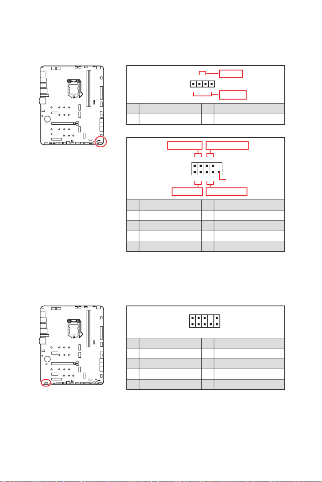
JFP1, JFP2: Front Panel Connectors
These connectors connect to the switches and LEDs on the front panel.
1
2 10
9
++
+- --
-
+
Power LED
HDD LED Reset Switch
Reserved
Power Switch
JFP1
1 HDD LED + 2 Power LED +
3 HDD LED - 4 Power LED -
5 Reset Switch 6 Power Switch
7 Reset Switch 8 Power Switch
9 Reserved 10 No Pin
JAUD1: Front Audio Connector
This connector allows you to connect audio jacks on the front panel.
1
2 10
9
1 MIC L 2 Ground
3 MIC R 4 NC
5 Head Phone R 6 MIC Detection
7 SENSE_SEND 8 No Pin
9 Head Phone L 10 Head Phone Detection
1
JFP2
+
+-
-
Speaker
Buzzer
1 Speaker - 2 Buzzer +
3 Buzzer - 4 Speaker +

40 Overview of Components
24
131
12
ATX_PWR1
1 +3.3V 13 +3.3V
2 +3.3V 14 -12V
3 Ground 15 Ground
4 +5V 16 PS-ON#
5 Ground 17 Ground
6 +5V 18 Ground
7 Ground 19 Ground
8 PWR OK 20 Res
9 5VSB 21 +5V
10 +12V 22 +5V
11 +12V 23 +5V
12 +3.3V 24 Ground
5
4 1
8CPU_PWR1~2
1 Ground 5 +12V
2 Ground 6 +12V
3 Ground 7 +12V
4 Ground 8 +12V
⚠
Important
Make sure that all the power cables are securely connected to a proper ATX power
supply to ensure stable operation of the motherboard.
CPU_PWR1~2, ATX_PWR1, PCIE_PWR1: Power Connectors
These connectors allow you to connect an ATX power supply.
1 3
64
PCIE_PWR1
1 +12V 4 Ground
2 +12V 5 Ground
3 +12V 6 Ground

41
Overview of Components
JSLOW1: Slow Mode Booting Jumper
This jumper is used for LN2 cooling solution, that provides the extreme overclocking
conditions, to boot at a stable processor frequency and to prevent the system from
crashing.
JLN1~2: Low Temperature Booting Jumper
This jumper is used for liquid nitrogen cooling system to boot at an extreme low
temperature. Try to set it Enabled to increase the boot success rate.
⚠
Important
∙
Users will try extreme low temperature overclocking at their own risks. The
overclocking results will vary according to the CPU version.
∙
Please don’t set to when power-off or the system will be un-bootable.Enabled
Enabled
(Please enable this jumper
during BIOS POST.)
Normal
(Default)
Normal
(Default)
Enabled
(Please enable this jumper
during BIOS POST.)
Termékspecifikációk
| Márka: | MSI |
| Kategória: | lencse |
| Modell: | MEG Z590 UNIFY-X |
Szüksége van segítségre?
Ha segítségre van szüksége MSI MEG Z590 UNIFY-X, tegyen fel kérdést alább, és más felhasználók válaszolnak Önnek
Útmutatók lencse MSI

15 December 2024
15 December 2024
10 Október 2024
17 Augusztus 2024
10 Augusztus 2024
31 Július 2024
21 Július 2024
13 Július 2024
10 Július 2024
27 Május 2024
Útmutatók lencse
- lencse Samsung
- lencse Sony
- lencse Olympus
- lencse Panasonic
- lencse Canon
- lencse Fujifilm
- lencse Gigabyte
- lencse Kodak
- lencse Nikon
- lencse Optoma
- lencse COLBOR
- lencse Bresser
- lencse Godox
- lencse Marshall
- lencse Sigma
- lencse Pentax
- lencse ARRI
- lencse Gaggenau
- lencse Leica
- lencse Lensbaby
- lencse Axis
- lencse ECS
- lencse InLine
- lencse Vivitar
- lencse Zeiss
- lencse Flir
- lencse Vello
- lencse Celly
- lencse Aputure
- lencse Carl Zeiss
- lencse Hasselblad
- lencse Teradek
- lencse Tamron
- lencse Brinno
- lencse Computar
- lencse Hanwha
- lencse Pelco
- lencse Laowa
- lencse Cambo
- lencse Irix
- lencse Tokina
- lencse Accsoon
- lencse NiSi
- lencse DZOFilm
- lencse Viltrox
- lencse Fujinon
- lencse TTArtisan
- lencse Samyang
Legújabb útmutatók lencse

10 Április 2025

4 Április 2025

3 Április 2025

2 Április 2025
2 Április 2025
2 Április 2025
2 Április 2025
2 Április 2025
2 Április 2025
2 Április 2025