Használati útmutató MSI MAG X570S TOMAHAWK MAX WIFI
Olvassa el alább 📖 a magyar nyelvű használati útmutatót MSI MAG X570S TOMAHAWK MAX WIFI (172 oldal) a lencse kategóriában. Ezt az útmutatót 10 ember találta hasznosnak és 2 felhasználó értékelte átlagosan 4.5 csillagra
Oldal 1/172
I
Quick Start

II Quick Start
1
2
3
6
4
5
7
8
9
Youtube
https://youtu.be/Xv89nhFk1vc
CPU_FAN1
⚽
Installing a Processor/ Installation des Prozessors/ Installer un
processeur/ Установка процессора

III
Quick Start
1
23
⚠
Important
If you are installing the screw-type CPU heatsink, please follow the figure below to
remove the retention module first and then install the heatsink.
Wenn Sie einen CPU-Kühler mit Schraubenbefestigung einsetzen, folgen Sie bitte
den Anweisungen unten um das Retention-Modul zu entfernen und den Kühler zu
installieren.
Si vous voulez installer un ventirad pour processeur à vis, veuillez suivre les
instructions ci-dessous pour d’abord retirer le module de rétention puis installer le
ventirad.
В случае установки процессорного кулера с системой крепления на винтах,
следуйте указаниям на рисунке ниже для снятия пластикового модуля крепления.
Затем установите кулер.

IV Quick Start
http://youtu.be/T03aDrJPyQs
Youtube
DIMMA2 DIMMA2
DIMMB2
DIMMA1
DIMMA2
DIMMB1
DIMMB2
⚽
Installing DDR4 memory/ Installation des DDR4-Speichers/
Installer une mémoire DDR4/ Установка памяти DDR4

VI Quick Start
Installing the Motherboard/ Installation des Motherboards/
Installer la carte mère/ Установка материнской платы
B A T1
2
Torque:
3 kgf·cm*
*3 kgf·cm
= 0.3 N·m
= 2.6 lbf·in
1
https://youtu.be/wWI6Qt51Wnc
⚽
Youtube
VII
Quick Start
http://youtu.be/gkDYyR_83I4
Youtube
ATX_PWR1 CPU_PWR1
⚽
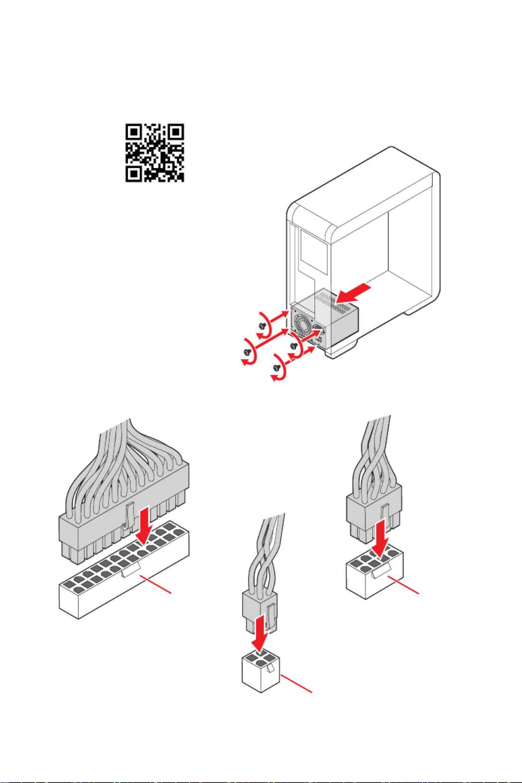
Connecting the Power Connectors/ Stromanschlüsse
anschliessen/ Connecter les câbles du module d’alimentation/
Подключение разъемов питания
CPU_PWR2

VIII Quick Start
http://youtu.be/RZsMpqxythc
Youtube
1
23
4
5
⚽
Installing SATA Drives/ Installation der SATA-Laufwerke/
Installer le disque dur SATA/ Установка дисков SATA

IX
Quick Start
http://youtu.be/mG0GZpr9w_A
Youtube
1
2
3
4
5
6
⚽
Installing a Graphics Card/ Einbau der Grafikkarte/ Installer
une carte graphique/ Установка дискретной видеокарты

XQuick Start
Connecting Peripheral Devices/ Peripheriegeräte/ Connecter
un périphérique anschliessen/ Подключение периферийных
устройств
∙MAG X570S TOMAHAWK MAX WIFI
Processor with integrated graphics

XI
Quick Start
·MAG X570S TORPEDO MAX
Processor with integrated graphics
XII Quick Start
4
3
12
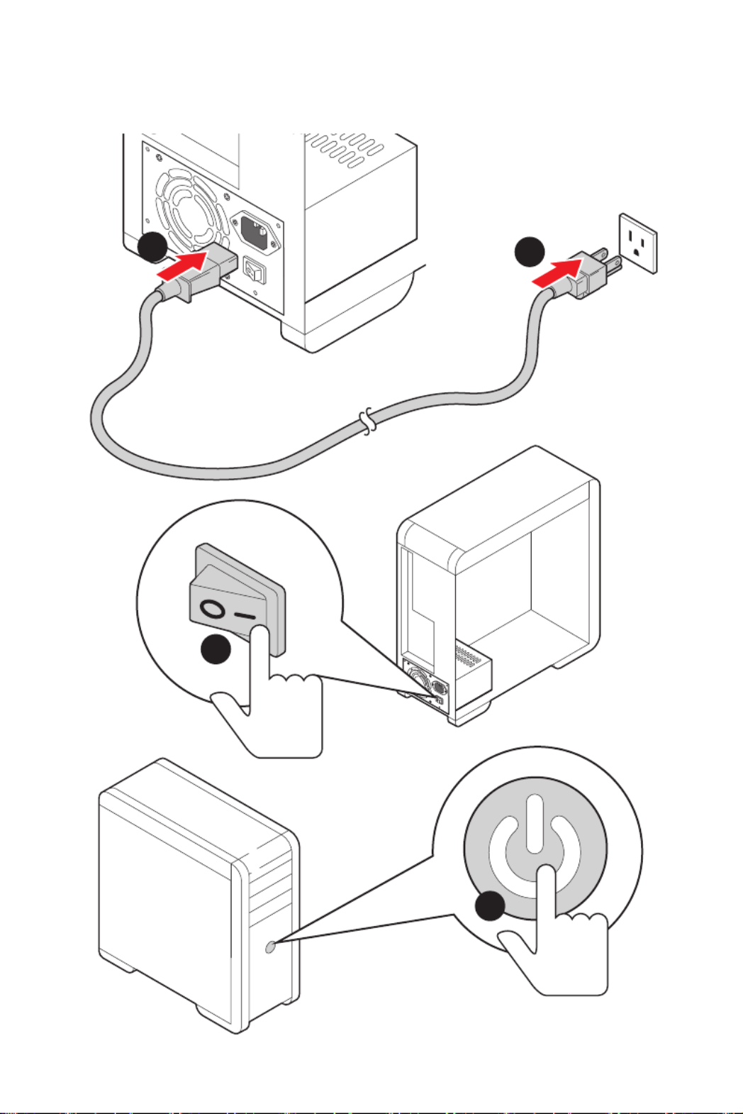
Power On/ Einschalten/ Mettre sous-tension/ Включение
питания

1
Contents
Contents
Safety Information ................................................................................................. 3
Case stand-off notification 4 .....................................................................................
Avoid collision notification 4 ......................................................................................
Specifications ......................................................................................................... 5
Package contents ................................................................................................ 12
Rear I/O Panel ..................................................................................................... 13
LAN Port LED Status Table 14 ..................................................................................
Audio Ports Configuration 14 ....................................................................................
Realtek Audio Console 15 .........................................................................................
Overview of Components .................................................................................... 18
CPU Socket 19 ...........................................................................................................
DIMM Slots 20 ............................................................................................................
PCI_E1~4: PCIe Expansion Slots 21 ..........................................................................
M2_1~2: M.2 Slots (Key M) 22 ...................................................................................
SATA1~6: SATA 6Gb/s Connectors 24 .......................................................................
JFP1, JFP2: Front Panel Connectors 24 ...................................................................
CPU_PWR1~2, ATX_PWR1: Power Connectors 25 ...................................................
CPU_FAN1, PUMP_FAN1, SYS_FAN1~4: Fan Connectors 26 ..................................
JUSB1~2: USB 2.0 Connectors 27 .............................................................................
JUSB3~4: USB 3.2 Gen 1 5Gbps Connectors 27 .......................................................
JUSB5: USB 3.2 Gen 2 10Gbps Type-C Connector 28 ...............................................
JAUD1: Front Audio Connector 28 ............................................................................
JCI1: Chassis Intrusion Connector 29 .......................................................................
JTPM1: TPM Module Connector 29 ...........................................................................
JCOM1: Serial Port Connector 30 .............................................................................
JBAT1: Clear CMOS (Reset BIOS) Jumper 30 ...........................................................
JPWRLED1: LED power input 31 ...............................................................................
EZ Debug LED 31 .......................................................................................................
JRGB1~2: RGB LED connectors 32 ...........................................................................
JRAINBOW1~2: Addressable RGB LED connectors 33 ............................................

2Contents
Installing OS, Drivers & MSI Center .................................................................... 34
Installing Windows® 10 34 .........................................................................................
Installing Drivers 34 ..................................................................................................
MSI Center 34 ............................................................................................................
UEFI BIOS ............................................................................................................. 35
BIOS Setup ........................................................................................................... 36
Entering BIOS Setup 36 .............................................................................................
BIOS User Guide 36 ...................................................................................................
Resetting BIOS 37 ......................................................................................................
Updating BIOS 37 .......................................................................................................
4Contents
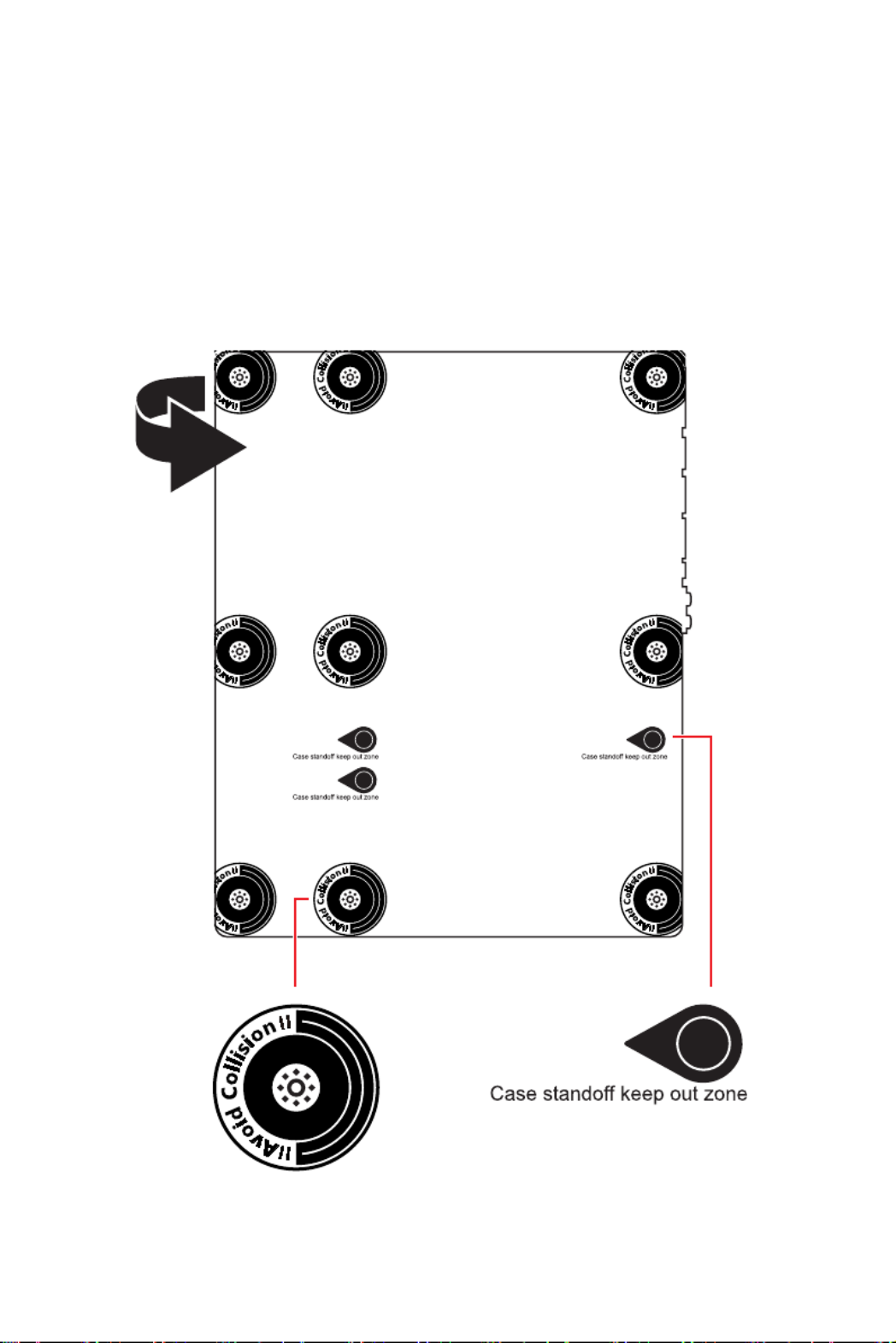
Case stand-off notification
To prevent damage to the motherboard, any unnecessary mounting stand-off between
the motherboard circuits and the computer case is prohibited. The Case standoff keep
out zone signs will be marked on the backside of motherboard (as shown below) to
serve as a warning to user.
Avoid collision notification
Protective paint is printed around each screw hole to prevent parts from being
scratched.

5
Specifications
Specifications
CPU
· Supports AMD Ryzen™ 5000 Series, 5000 G-Series, 4000
G-Series, 3000 Series, 3000 G-Series, 2000 Series and 2000
G-Series desktop processors*
· Supports Socket AM4
* Please go to msi.com to get the newest support status as new processors are
released.
Chipset AMD X570 Chipset
Memory
· 4x DDR4 memory slots, support up to 128GB
· Supports 1866/ 2133/ 2400/ 2667/ 2800/ 2933/ 3000/ 3066/
3200 MHz by JEDEC*
· Max overclocking frequency by A-XMP OC mode:
▪ For Ryzen™ 5000 G-Series & 4000 G-Series
processors
▫ 1DPC 1R Max speed up to 5100 MHz
▫ 1DPC 2R Max speed up to 4000 MHz
▫ 2DPC 1R Max speed up to 4266 MHz
▫ 2DPC 2R Max speed up to 3600 MHz
▪ For Ryzen™ 5000 Series & 3000 Series processors
▫ 1DPC 1R Max speed up to 5100 MHz
▫ 1DPC 2R Max speed up to 3866 MHz
▫ 2DPC 1R Max speed up to 4000 MHz
▫ 2DPC 2R Max speed up to 3600 MHz
· Supports Dual-Channel mode
· Supports non-ECC, un-buffered memory
*Please refer to msi.com for more information on compatible memory.
Expansion Slot
· Supports PCIe 4.0 / PCIe 3.0
▪ PCIe 4.0 is available only on AMD Ryzen™ 5000 Series
and desktop processors3000 Series
· 1x PCIe x16 slot (From processor)
▪ PCI_E1 supports PCIe 4.0/ 3.0 x16
▪ PCI_E1 supports PCIe 3.0 p17-x8 on AMD Ryzen™ 3000 G-
and series desktop processors2000 G-
· 1x PCIe x16 slot (From X570 chipset)
▪ PCI_E3 supports PCIe 4.0/ 3.0 x4
· 2x PCIe 3.0 p17-x1 slots (From X570 chipset)
Continued on next page

6Specifications
Continued from previous page
Onboard Graphics
· 1x HDMI 2.1 port, supports a maximum resolution of 4K
60Hz*/**
* Available only on processors featuring integrated graphics.
** Graphics specifications may vary depending on the CPU installed.
Multi-GPU Supports AMD CrossFire™ Technology
LAN
1x Realtek® 8125B 2.5Gbps LAN Controller
1x Realtek® RTL8111H 1Gbps LAN Controller (For MAG
X570S TORPEDO MAX)
Wireless LAN
& Bluetooth®
(For MAG X570S
TOMAHAWK MAX
WIFI)
Intel® Wi-Fi 6E AX210
· The Wireless module is pre-installed in the M.2 (Key-E)
slot
· Supports MU-MIMO TX/RX, 2.4GHz/ 5GHz/ 6GHz*
(160MHz) up to 2.4Gbps
· Supports 802.11 a/ b/ g/ n/ ac/ ax
· Supports Bluetooth® 5.2**, FIPS, FISMA
* Wi-Fi 6E 6GHz may depend on every country’s regulations and will be ready in
WIN10 21H1.
** Bluetooth 5.2 will be ready in WIN10 21H1.
Storage
· 6x SATA 6Gb/s ports (from AMD X570 Chipset)
· 2x M.2 slots (Key M)
▪ Supports PCIe 4.0 / PCIe 3.0
▪ PCIe 4.0 is available only on AMD Ryzen™ 5000 Series
and desktop processors3000 Series
▪ Supports up to SATA 6Gb/s
▪ M2_1 slot (from Processor)
▫ Support 2280/22110 storage devices
▪ M2_2 slot (from AMD X570 Chipset)
▫ Supports 2242/ 2260/ 2280 storage devices
RAID · Supports RAID 0, RAID 1 and RAID 10
Audio
· Realtek® ALC4080 Codec
▪ 7.1-Channel High Definition Audio
▪ Supports S/PDIF output
I/O Controller NUVOTON NCT6797D Controller Chip
Continued on next page

7
Specifications
Continued from previous page
Hardware Monitor
· CPU/ System/ Chipset temperature detection
· CPU/ System/ Pump fan speed detection
· CPU/ System/ Pump fan speed control
USB
AMD X570 Chipset
· 3x USB 3.2 Gen 2 10Gbps ports (2 Type-A ports on the
back panel, 1 Type-C internal connector)
· 4x USB 3.2 Gen 1 5Gbps ports available through the
internal USB 3.2 Gen 1 5Gbps connectors
· 1x USB 2.0 port on the back panel
USB 2.0 Hub
· 5x USB 2.0 ports (1 Type-A port on the back panel, 4 ports
available through the internal USB 2.0 connectors)
AMD Processor
· 2x USB 3.2 Gen 2 10Gbps ports on the back panel (Type-A
&Type-C)
· 2x USB 3.2 Gen 1 5Gbps Type-A ports on the back panel
Back Panel
Connectors
· 1x Flash BIOS Button
· 1x PS/2 keyboard/ mouse combo port
· 2x USB 2.0 ports
· 2x Wi-Fi Antenna connectors (For MAG X570S TOMAHAWK
MAX WIFI)
· 2x USB 3.2 Gen1 5Gbps Type-A ports
· 1x HDMI port
· 3x USB 3.2 Gen 2 10Gbps Type-A port
· 1x USB 3.2 Gen 2 10Gbps Type-C port
· 1x 2.5Gbps LAN port
· 1x 1Gbps LAN port (For MAG X570S TORPEDO MAX)
· 5x audio jacks
· 1x Optical S/PDIF Out connector
Continued on next page

8Specifications
Continued from previous page
Internal Connectors
· 1x 24-pin ATX main power connector
· 1x 8-pin ATX 12V power connector
· 1x 4-pin ATX 12V power connector
· 6x SATA 6Gb/s connectors
· 2x USB 2.0 connectors (supports additional 4 USB 2.0
ports)
· 2x USB 3.2 Gen 1 5Gbps connectors (supports additional 4
USB 3.2 Gen 1 5Gbps ports)
· 1x USB 3.2 Gen 2 10Gbps Type-C port
· 1x 4-pin CPU fan connector
· 1x 4-pin water-pump connector
· 4x 4-pin system fan connectors
· 1x Front panel audio connector
· 2x System panel connectors
· 1x Chassis Intrusion connector
· 1x TPM module connector
· 1x Serial port connector
Jumpers · 1x Clear CMOS jumper
LED Features
· 2x 4-pin RGB LED connectors
· 2x 3-pin RAINBOW LED connectors
· 4x EZ Debug LED
· 1X EZ LED Control switch
BIOS Features
· 1x 256 Mb flash
· UEFI AMI BIOS
· ACPI 6.1, SM BIOS 2.8
· Multi-language
Form Factor · ATX Form Factor
· 12 in. x 9.6 in. (30.5 cm x 24.4 cm)
Continued on next page

9
Specifications
Continued from previous page
Software
· Drivers
· MSI Center
· CPU-Z MSI GAMING
· Open Broadcaster Software (OBS)
· MSI App Player (BlueStacks)
· Google Chrome™, Google Toolbar, Google Drive
· Norton™ Internet Security Solution
MSI Center
Features
· Gaming Mode
· Smart Priority
· Game Highlights
· LAN Manager
· Mystic Light
· Ambient Link (For MAG X570S TOMAHAWK MAX WIFI)
· Frozr AI Cooling
· User Scenario
· True Color
· Live Update
· Monitor
· Super Charger
· Speed Up
· Smart Image Finder
· MSI Companion
Special Features
· Audio
▪ Audio Boost 5
· Network
▪ 2.5G LAN
▪ 1G LAN (For MAG X570S TORPEDO MAX)
▪ Intel WiFi 6E (For MAG X570S TOMAHAWK MAX WIFI)
Continued on next page

10 Specifications
Continued from previous page
Special Features
· Cooling
▪ M.2 Shield Frozr
▪ All Aluminum Design (For MAG X570S TOMAHAWK
MAX WIFI)
▪ Extended Heatsink Design (For MAG X570S TORPEDO
MAX)
▪ Pump Fan
▪ Smart Fan Control
▪ K7 thermal pad
▪ Choke pad
· Storage
▪ Lightning Gen 4 M.2
▪ Twin Turbo M.2
· LED
▪ Mystic Light
▪ Mystic Light Extension (RAINBOW/RGB)
▪ Mystic Light SYNC
▪ Ambient Link (For MAG X570S TOMAHAWK MAX WIFI)
▪ EZ LED Control
▪ EZ DEBUG LED
· Performance
▪ Lightning Gen 4 PCI-E Slot
▪ Multi GPU-CrossFire Technology
▪ DDR4 Boost
▪ Core Boost
▪ GAME Boost
▪ USB with type A+C
▪ USB 3.2 Gen 2 10G
▪ Front USB Type-C
▪ 2oz Copper thickened PCB
▪ Dual CPU Power
Continued on next page

11
Specifications
Continued from previous page
Special Features
· Protection
▪ PCI-E Steel Armor
▪ Pre-installed IO shielding
· Experience
▪ MSI Center
▪ Frozr AI Cooling
▪ Click BIOS 5
▪ Flash BIOS Button

12 Package contents
Package contents
Please check the contents of your motherboard package. It should contain:
Motherboard MAG X570S TOMAHAWK MAX WIFI/ MAG X570S TORPEDO
MAX
Cable SATA 6Gb/s cable 2
Accessories
Wi-Fi antenna (For MAG X570S TOMAHAWK MAX
WIFI) 1
M.2 screw + standoff (2 sets/pack) 1
Case badge 1
MAG Sticker 1
Product registration card 1
MSI Reward Program 1
Application USB drive with drivers & utilities 1
Documentation User manual 1
Quick installation guide 1
⚠
Important
If any of the above items are damaged or missing, please contact your retailer.
13
Rear I/O Panel
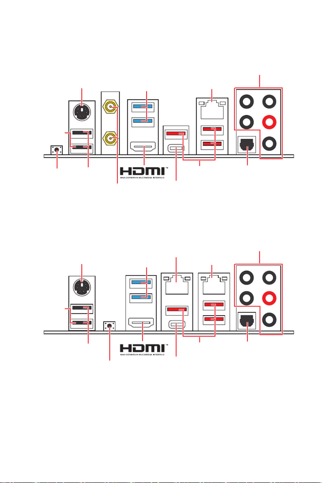
Rear I/O Panel
· MAG X570S TOMAHAWK MAX WIFI
· Flash BIOS Port/ Button - Please refer to page 38 for Updating BIOS with Flash BIOS
Button.
USB 3.2
Gen 2
(10Gbps)
Type-A
USB 3.2
Gen 2
(10Gbps)
Type-A
USB 3.2
Gen 2
(10Gbps)
Type-C
USB 3.2
Gen 2
(10Gbps)
Type-C
2.5Gbps LAN
2.5Gbps LAN
Audio Ports
Audio Ports
Optical
S/PDIF-Out
Optical
S/PDIF-Out
USB 2.0
Type-A
USB 2.0
Type-A
USB 3.2
Gen1
(5Gbps)
Type-A
USB 3.2
Gen1
(5Gbps)
Type-A
PS/2 Mouse/
Keyboard
PS/2 Mouse/
Keyboard
Wi-Fi Antenna
connectors
Flash BIOS
Button
Flash BIOS
Button
Flash BIOS
Port
Flash BIOS
Port
· MAG X570S TORPEDO MAX
1Gbps LAN

14 Rear I/O Panel
Link/ Activity LED
Status Description
Off No link
Yellow Linked
Blinking Data activity
Speed LED
Status Description
Off 10 Mbps connection
Green 100 Mbps/ 1 Gbps
Orange 2.5 Gbps connection
LAN Port LED Status Table
Audio Ports Configuration
Audio Ports Channel
2 4 6 8
Center/ Subwoofer Out ● ●
Rear Speaker Out ● ● ●
Line-In/ Side Speaker Out ●
Line-Out/ Front Speaker Out ● ● ● ●
Mic In
( : connected, : empty)●Blank

15
Rear I/O Panel
Realtek Audio Console
After Realtek Audio Console is installed. You can use it to change sound settings to get
better sound experience.
· Device Selection - allows you to select a audio output source to change the related
options. The sign indicates the devices as default.check
· Application Enhancement - the array of options will provide you a complete
guidance of anticipated sound effect for both output and input device.
· Main Volume - controls the volume or balance the right/left side of the speakers
that you plugged in front or rear panel by adjust the bar.
· Jack Status - depicts all render and capture devices currently connected with your
computer.
· Connector Settings - configures the connection settings.
Auto popup dialog
When you plug into a device at an audio jack, a dialogue window will pop up asking you
which device is current connected.
Each jack corresponds to its default setting as shown on the next page.
⚠
Important
The pictures above for reference only and may vary from the product you purchased.
Jack Status
Connector Settings
Device
Selection
Main Volume
Application Enhancement

16 Rear I/O Panel
Audio jacks to headphone and microphone diagram
Audio jacks to stereo speakers diagram
Audio jacks to 7.1-channel speakers diagram
AUDIO INPUT
AUDIO INPUT
Rear Front
Side Center/
Subwoofer

17
Rear I/O Panel
Installing antennas
1. Screw the antennas tight to the antenna connectors as shown below.
2. Orient the antennas.
1
2

18 Overview of Components
Overview of Components
BAT1
Processor Socket
DIMMB1
DIMMB2
JCI1
JBAT1
M2_1
M2_2
PCI_E4
PCI_E3
PCI_E2
PCI_E1
JAUD1
DIMMA1
DIMMA2
SATA ▼ 1 ▲ 2
SATA ▼ 3 ▲ 4
SATA ▼ 5 ▲ 6
JRAINBOW2
JRGB2
CPU_FAN1
PUMP_FAN1
SYS_FAN2
SYS_FAN1
SYS_FAN4
SYS_FAN3
ATX_PWR1
JUSB5
JUSB4
JUSB3
JUSB2
JUSB1
JCOM1
JTPM1
JRGB1
CPU_PWR1
CPU_PWR2
JRAINBOW1
JPWRLED1
JFP1
JFP2

19
Overview of Components
CPU Socket
Introduction to the AM4 CPU
The surface of the AM4 CPU has a
yellow triangle to assist in correctly
lining up the CPU for motherboard
placement. The yellow triangle is
the Pin 1 indicator.
53.5 mm
Distance from the center of the
CPU to the nearest DIMM slot.
⚠
Important
·
When changing the processor, the system configuration could be cleared and reset
BIOS to default values, due to the AM4 processor’s architecture.
·
Always unplug the power cord from the power outlet before installing or removing
the CPU.
·
When installing a CPU, always remember to install a CPU heatsink. A CPU heatsink
is necessary to prevent overheating and maintain system stability.
·
Confirm that the CPU heatsink has formed a tight seal with the CPU before booting
your system.
·
Overheating can seriously damage the CPU and motherboard. Always make sure
the cooling fans work properly to protect the CPU from overheating. Be sure to apply
an even layer of thermal paste (or thermal tape) between the CPU and the heatsink to
enhance heat dissipation.
·
If you purchased a separate CPU and heatsink/ cooler, Please refer to the
documentation in the heatsink/ cooler package for more details about installation.
·
This motherboard is designed to support overclocking. Before attempting to
overclock, please make sure that all other system components can tolerate
overclocking. Any attempt to operate beyond product specifications is not
recommended. MSI® does not guarantee the damages or risks caused by inadequate
operation beyond product specifications.

20 Overview of Components
DIMM Slots
DIMMA1 DIMMB1
Channel A Channel B
DIMMA2 DIMMB2
Memory module installation recommendation
DIMMB2 DIMMB2
DIMMB1
DIMMA2 DIMMA2 DIMMA2
DIMMA1
⚠
Important
·
Always insert memory modules in the slot first.DIMMA2
·
To ensure system stability for Dual channel mode, memory modules must be of the
same type, number and density.
·
Some memory may operate at a lower frequency than the marked value when
overclocking due to the memory frequency operates dependent on its Serial Presence
Detect (SPD). Go to BIOS and find the to set the memory frequency if DRAM Frequency
you want to operate the memory at the marked or at a higher frequency.
·
It is recommended to use a more efficient memory cooling system for full DIMMs
installation or overclocking.
·
The stability and compatibility of installed memory module depend on installed CPU
and devices when overclocking.
·
Please refer www.msi.com for more information on compatible memory.

21
Overview of Components
PCI_E1~4: PCIe Expansion Slots
⚠
Important
·
If you install a large and heavy graphics card, you need to use a tool such as MSI
Gaming Series Graphics Card Bolster to support its weight to prevent deformation of
the slot.
·
For a single PCIe x16 expansion card installation with optimum performance, using
the slot is recommended.PCI_E1
·
When adding or removing expansion cards, always turn off the power supply and
unplug the power supply power cable from the power outlet. Read the expansion
card’s documentation to check for any necessary additional hardware or software
changes.
BAT1
PCI_E1: PCIe x16 slot (CPU)
PCI_E3: PCIe p33-x4 slot (Chipset)
PCI_E4: PCIe p33-x1 slot (Chipset)
PCI_E2: PCIe p33-x1 slot (Chipset)
Slots AMD Ryzen™
5000/ 3000 series
processors
AMD Ryzen™ 5000
G-/ 4000 G-/ 2000
series processors
AMD Ryzen™ 3000
G-/ 2000 G- series
processors
PCI_E1 (CPU) PCIe 4.0 x16 PCIe 3.0 x16 PCIe 3.0 x8
PCI_E2 (Chipset) PCIe 3.0 p33-x1 PCIe 3.0 p33-x1 PCIe 3.0 p33-x1
PCI_E3 (Chipset) PCIe 4.0 x4 PCIe 3.0 x4 PCIe 3.0 x4
PCI_E4 (Chipset) PCIe 3.0 x1 PCIe 3.0 x1 PCIe 3.0 x1

22 Overview of Components
M2_1~2: M.2 Slots (Key M)
M2_1 (CPU)
M2_2 (Chipset)
Installing M.2 module
1. Loosen the screws of M.2 SHIELD FROZR heatsink.
2. Remove the M.2 SHIELD FROZR and remove the protective films from the thermal
pads.
1
1
1
1
2
Video Demonstration
Watch the video to learn how to Install
M.2 SSD.
https://youtu.be/2UeWMgjwogU

23
Overview of Components
6
6
6
6
6. Put the M.2 SHIELD FROZR heatsink back in place and secure it.
3. Secure the supplied M.2 standoff according to your M.2 SSD length if need.
4. Insert your M.2 SSD into the M.2 slot at a 30-degree angle.
5. Secure the M.2 SSD in place with the supplied M.2 8.5H screw.
⚠
Important
Skip step 3 and step 5, if you install 22110 M.2 into M2_1 slot or install 2280 M.2 into
M2_2 slot.
30º30º
M.2 standoff
heatsink standoff
3
5
4
M.2 screw
24 Overview of Components
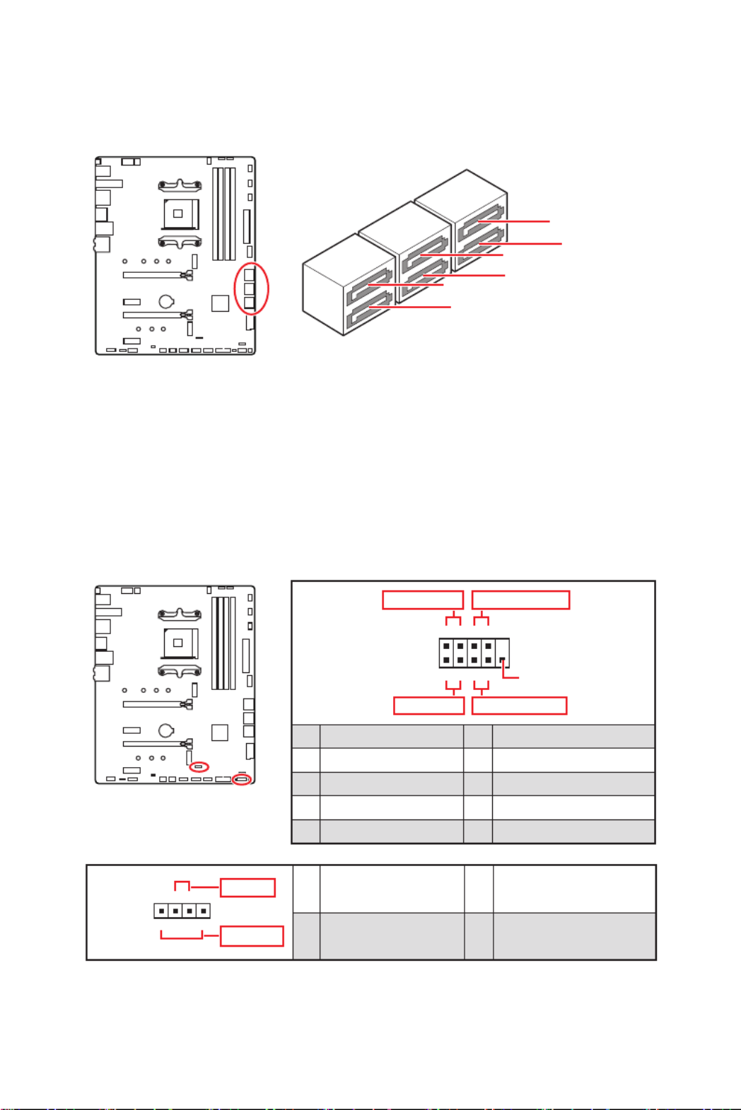
JFP1, JFP2: Front Panel Connectors
These connectors connect to the switches and LEDs on the front panel.
1
2 10
9
++
+- --
-
+
Power LED
HDD LED Reset Switch
Reserved
Power Switch
JFP1
1 HDD LED + 2 Power LED +
3 HDD LED - 4 Power LED -
5 Reset Switch 6 Power Switch
7 Reset Switch 8 Power Switch
9 Reserved 10 No Pin
1JFP2
+
+-
-
Speaker
Buzzer 1 Speaker - 2 Buzzer +
3 Buzzer - 4 Speaker +
SATA1~6: SATA 6Gb/s Connectors
These connectors are SATA 6Gb/s interface ports. Each connector can connect to one
SATA device.
⚠
Important
·
Please do not fold the SATA cable at a 90-degree angle. Data loss may result during
transmission otherwise.
·
SATA cables have identical plugs on either sides of the cable. However, it is
recommended that the flat connector be connected to the motherboard for space
saving purposes.
SATA1
SATA3
SATA2
SATA4
SATA5
SATA6

25
Overview of Components
24
131
12
ATX_PWR1
1 +3.3V 13 +3.3V
2 +3.3V 14 -12V
3 Ground 15 Ground
4 +5V 16 PS-ON#
5 Ground 17 Ground
6 +5V 18 Ground
7 Ground 19 Ground
8 PWR OK 20 Res
9 5VSB 21 +5V
10 +12V 22 +5V
11 +12V 23 +5V
12 +3.3V 24 Ground
5
4 1
8CPU_PWR1
1 Ground 5 +12V
2 Ground 6 +12V
3 Ground 7 +12V
4 Ground 8 +12V
⚠
Important
Make sure that all the power cables are securely connected to a proper ATX power
supply to ensure stable operation of the motherboard.
CPU_PWR1~2, ATX_PWR1: Power Connectors
These connectors allow you to connect an ATX power supply.
3
2 1
4CPU_PWR2
1 Ground 3 +12V
2 Ground 4 +12V

26 Overview of Components
Switching fan mode and adjusting fan speed
You can switch between PWM mode and DC mode and adjust fan speed in BIOS >
HARDWARE MONITOR.
Select mode or modePWM DC
⚠
Important
Make sure fans are working properly after switching the PWM/ DC mode.
There are gradient points of the fan speed that allow you to adjust
fan speed in relation to CPU temperature.
PWM Mode pin definition
1 Ground 2 +12V
3 Sense 4 Speed Control Signal
DC Mode pin definition
1 Ground 2 Voltage Control
3 Sense 4 NC
Pin definition of fan connectors
CPU_FAN1, PUMP_FAN1, SYS_FAN1~4: Fan Connectors
Fan connectors can be classified as PWM (Pulse Width Modulation) Mode or DC Mode.
PWM Mode fan connectors provide constant 12V output and adjust fan speed with
speed control signal. DC Mode fan connectors control fan speed by changing voltage.
You can follow the instruction below to adjust the fan connector to PWM or DC Mode.
Connector Default
fan mode Max.
current Max.
power
CPU_FAN1 Auto mode 2A 24W
PUMP_FAN1 PWM mode 2A 36W
SYS_FAN1~4 DC mode 1A 12W
CPU_FAN1
PUMP_FAN1
SYS_FAN2
SYS_FAN3 SYS_FAN4
SYS_FAN1

27
Overview of Components
JUSB3~4: USB 3.2 Gen 1 5Gbps Connectors
These connectors allow you to connect USB 3.2 Gen 1 5Gbps ports on the front panel.
⚠
Important
Note that the Power and Ground pins must be connected correctly to avoid possible
damage.
1
10 11
20
JUSB4
1 10
1120
JUSB3
1 Power 11 USB2.0+
2 USB3_RX_DN 12 USB2.0-
3 USB3_RX_DP 13 Ground
4 Ground 14 USB3_TX_C_DP
5 USB3_TX_C_DN 15 USB3_TX_C_DN
6 USB3_TX_C_DP 16 Ground
7 Ground 17 USB3_RX_DP
8 USB2.0- 18 USB3_RX_DN
9 USB2.0+ 19 Power
10 NC 20 No Pin
JUSB1~2: USB 2.0 Connectors
These connectors allow you to connect USB 2.0 ports on the front panel.
1
2 10
9
1 VCC 2 VCC
3 USB0- 4 USB1-
5 USB0+ 6 USB1+
7 Ground 8 Ground
9 No Pin 10 NC
⚠
Important
·
Note that the VCC and Ground pins must be connected correctly to avoid possible
damage.
·
In order to recharge your iPad, iPhone and iPod through USB ports, please install
MSI Center utility.

28 Overview of Components
JAUD1: Front Audio Connector
This connector allows you to connect audio jacks on the front panel.
1
2 10
9
1 MIC L 2 Ground
3 MIC R 4 NC
5 Head Phone R 6 MIC Detection
7 SENSE_SEND 8 No Pin
9 Head Phone L 10 Head Phone Detection
JUSB5: USB 3.2 Gen 2 10Gbps Type-C Connector
This connector allows you to connect USB 3.2 Gen 2 10Gbps Type-C connector on the
front panel. The connector possesses a foolproof design. When you connect the cable,
be sure to connect it with the corresponding orientation.
JUSB5 USB Type-C Cable
USB Type-C port on
the front panel
29
Overview of Components
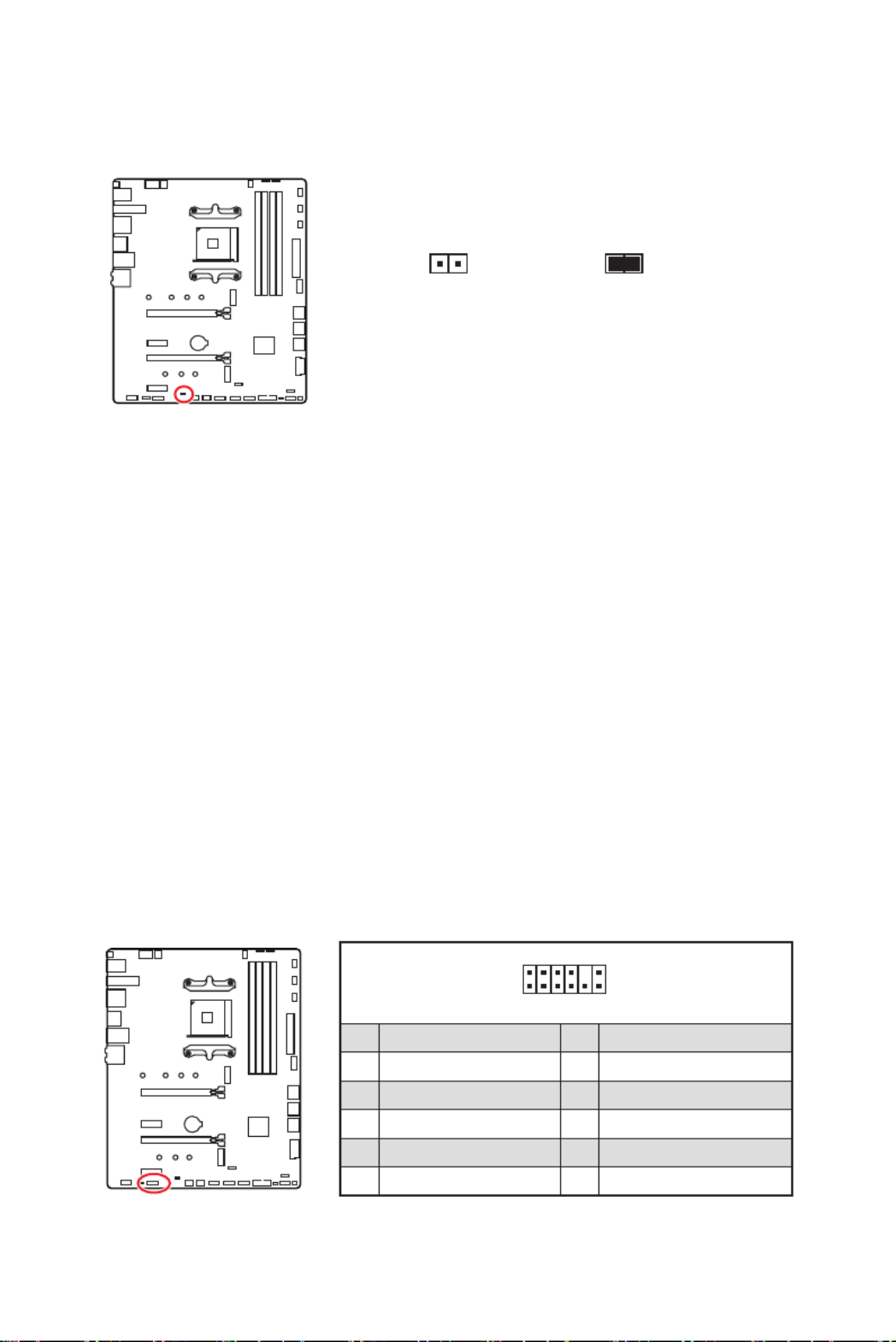
JCI1: Chassis Intrusion Connector
This connector allows you to connect the chassis intrusion switch cable.
Normal
(default)
Trigger the chassis
intrusion event
Using chassis intrusion detector
1. JCI1Connect the connector to the chassis intrusion switch/ sensor on the chassis.
2. Close the chassis cover.
3. BIOS > SETTINGS > Security > Chassis Intrusion ConfigurationGo to .
4. Chassis Intrusion EnabledSet to .
5. F10 Enter YesPress to save and exit and then press the key to select .
6. Once the chassis cover is opened again, a warning message will be displayed on
screen when the computer is turned on.
Resetting the chassis intrusion warning
1. BIOS > SETTINGS > Security > Chassis Intrusion ConfigurationGo to .
2. Chassis Intrusion ResetSet to .
3. F10 Enter YesPress to save and exit and then press the key to select .
JTPM1: TPM Module Connector
This connector is for TPM (Trusted Platform Module). Please refer to the TPM security
platform manual for more details and usages.
1
2 12
11
1 SPI Power 2 SPI Chip Select
3
Master In Slave Out (SPI Data)
4
Master Out Slave In (SPI Data)
5 Reserved 6 SPI Clock
7 Ground 8 SPI Reset
9 Reserved 10 No Pin
11 Reserved 12 Interrupt Request

31
Overview of Components
EZ Debug LED
These LEDs indicate the debug status of the motherboard.
- indicates CPU is not detected or fail.CPU
- indicates DRAM is not detected or fail.DRAM
- indicates GPU is not detected or fail.VGA
- indicates the booting device is not detected BOOT or fail.
JPWRLED1: LED power input
This connector is used by retailers to demonstrate onboard LED light effects.
JPWRLED1 - LED power input

33
Overview of Components
1
D
+5V
1
1
⚠
CAUTION
Do not connect the wrong type of LED strips. The JRGB connector and the JRAINBOW
connector provide different voltages, and connecting the 5V LED strip to the JRGB
connector will result in damage to the LED strip.
⚠
Important
∙
The JRAINBOW connector supports up to 75 LEDs WS2812B Individually
Addressable RGB LED strips (5V/Data/Ground) with the maximum power rating of 3A
(5V). In the case of 20% brightness, the connector supports up to 200 LEDs.
∙
Always turn off the power supply and unplug the power cord from the power outlet
before installing or removing the RGB LED strip.
∙
Please use MSI’s software to control the extended LED strip.
JRAINBOW1~2: Addressable RGB LED connectors
The JRAINBOW connectors allow you to connect the WS2812B Individually
Addressable RGB LED strips 5V.
JRAINBOW
connector
JRAINBOW connector
System Fan connector
Rainbow RGB LED
extension cable
(optional)
WS2812B Individually
Addressable RGB LED strips 5V
1
1 +5V 2 Data
3 No Pin 4 Ground
Addressable RGB LED Strip Connection
Addressable RGB LED Fan Connection
Addressable RGB LED Fan

34 Installing OS, Drivers & MSI Center
Installing OS, Drivers & MSI Center
Please download and update the latest utilities and drivers at www.msi.com
Installing Windows® 10
1. Power on the computer.
2. Insert the Windows® 10 installation disc/USB into your computer.
3. RestartPress the button on the computer case.
4. F11Press key during the computer POST (Power-On Self Test) to get into Boot
Menu.
5. Select the Windows® 10 installation disc/USB from the Boot Menu.
6. Press any key to boot from CD or DVD...Press any key when screen shows
message.
7. Follow the instructions on the screen to install Windows® 10.
Installing Drivers
1. Start up your computer in Windows® 10.
2. Insert MSI® USB Drive into the USB port.
3. Select to choose what happens with this disc Click the pop-up notification, then
select to open the installer. If you turn off the AutoPlay feature Run DVDSetup.exe
from the Windows Control Panel, you can still manually execute the DVDSetup.exe
from the root path of the MSI USB Drive.
4. Drivers/SoftwareThe installer will find and list all necessary drivers in the tab.
5. InstallClick the button in the lower-right corner of the window.
6. The drivers installation will then be in progress, after it has finished it will prompt
you to restart.
7. OKClick button to finish.
8. Restart your computer.
MSI Center
MSI Center is an application that helps you easily optimize game settings and smoothly
use content creation softwares. It also allows you to control and synchronize LED
light effects on PCs and other MSI products. With MSI Center, you can customize ideal
modes, monitor system performance, and adjust fan speed.
MSI Center User Guide
If you would like to know more information about MSI Center, please
refer to
http://download.msi.com/manual/mb/MSICENTER.pdf
or scan the QR code to access.
⚠
Important
Functions may vary depending on the product you have.

35
UEFI BIOS
UEFI BIOS
MSI UEFI BIOS is compatible with UEFI (Unified Extensible Firmware Interface)
architecture. UEFI has many new functions and advantages that traditional BIOS
cannot achieve, and it will completely replace BIOS in the future. The MSI UEFI
BIOS uses UEFI as the default boot mode to take full advantage of the new chipset’s
capabilities.
⚠
Important
The term BIOS in this user guide refers to UEFI BIOS unless otherwise noted.
UEFI advantages
∙Fast booting - UEFI can directly boot the operating system and save the BIOS self-
test process. And also eliminates the time to switch to CSM mode during POST.
∙Supports for hard drive partitions larger than 2 TB.
∙Supports more than 4 primary partitions with a GUID Partition Table (GPT).
∙Supports unlimited number of partitions.
∙Supports full capabilities of new devices - new devices may not provide backward
compatibility.
∙Supports secure startup - UEFI can check the validity of the operating system to
ensure that no malware tampers with the startup process.
Incompatible UEFI cases
∙32-bit Windows operating system - this motherboard supports only Windows 10
64-bit operating system.
∙Older graphics card - the system will detect your graphics card. When display a
warning message There is no GOP (Graphics Output protocol) support detected in
this graphics card.
⚠
Important
We recommend that you to replace with a GOP/UEFI compatible graphics card or
using integrated graphics from CPU for having normal function.
How to check the BIOS mode?
1. Power on your computer.
2. Delete Press DEL key to enter Setup Menu, F11 to enter Press key, when the
Boot Menu message appears on the screen during the boot process.
3. BIOS ModeAfter entering the BIOS, you can check the at the top of the screen.
BIOS Mode: UEFI

36 BIOS Setup
BIOS Setup
The default settings offer the optimal performance for system stability in normal
conditions. You should to avoid possible system always keep the default settings
damage or failure booting unless you are familiar with BIOS.
⚠
Important
∙
BIOS items are continuously update for better system performance. Therefore, the
description may be slightly different from the latest BIOS and should be for reference
only. You could also refer to the information panel for BIOS item description.HELP
∙
The pictures in this guide are for reference only .
∙
The BIOS screens, options and settings will vary depending on your system.
Entering BIOS Setup
Press key, when theDelete Press DEL key to enter Setup Menu, F11 to enter Boot
Menu message appears on the screen during the boot process.
Function key
F1: General Help list
F2: Add/ Remove a favorite item
F3: Enter Favorites menu
F4: Enter CPU Specifications menu
F5: Enter Memory-Z menu
F6: Load optimized defaults
F7: Switch between Advanced mode and EZ mode
F8: Load Overclocking Profile
F9: Save Overclocking Profile
F10: Save Change and Reset*
F12: Take a screenshot and save it to USB flash drive (FAT/ FAT32 format only).
Ctrl+F: Enter Search page
* When you press F10, a confirmation window appears and it provides the modification
information. Select between Yes or No to confirm your choice.
BIOS User Guide
If you’d like to know more instructions on setting up the BIOS, please
refer to
http://download.msi.com/manual/mb/AMDX570BIOS.pdf
or scan the QR code to access.

38 BIOS Setup
Updating the BIOS with MSI Center
Before updating:
∙Make sure the LAN driver is already installed and the internet connection is set
properly.
∙Please close all other application software before updating the BIOS.
To update BIOS:
1. SupportInstall and launch MSI Center and go to page.
2. Live Update AdvanceSelect and click on button.
3. InstallSelect the BIOS file and click on button.
4. The installation reminder will appear, then click the Install button on it.
5. The system will automatically restart to update BIOS.
6. After the flashing process is 100% completed, the system will restart
automatically.
Updating BIOS with Flash BIOS Button
1. Please download the latest BIOS file that matches your motherboard model from
the MSI® website.
2. Rename the BIOS file to MSI.ROM, and save it to the root of the USB 2.0 storage
device.
3. CPU_PWR1 ATX_PWR1Connect the power supply to and . (No need to install CPU
and memory.)
4. Flash Plug the USB 2.0 storage device that contains the MSI.ROM file into the
BIOS Port on the rear I/O panel.
5. Flash BIOS Press the Button to flash BIOS, and the LED starts flashing.
6. The LED will be turned off when the process is completed.

3
Sicherheitshinweis
Sicherheitshinweis
∙Die im Paket enthaltene Komponenten sind der Beschädigung durch
elektrostatischen Entladung (ESD). Beachten Sie bitte die folgenden Hinweise, um die
erfolgreichen Computermontage sicherzustellen.
∙Stellen Sie sicher, dass alle Komponenten fest angeschlossen sind. Lockere
Steckverbindungen können Probleme verursachen, zum Beispiel: Der Computer
erkennt eine Komponente nicht oder startet nicht.
∙Halten Sie das Motherboard nur an den Rändern fest, und verhindern Sie die
Berührung der sensiblen Komponenten.
∙Um eine Beschädigung der Komponenten durch elektrostatische Entladung
(ESD) zu vermeiden, sollten Sie eines elektrostatischen Armbands während der
Handhabung des Motherboards tragen. Wenn kein elektrostatischen Handgelenkband
vorhanden ist, sollten Sie Ihre statische Elektrizität ableiten, indem Sie ein anderes
Metallobjekt berühren, bevor Sie das Motherboard anfassen.
∙Bewahren Sie das Motherboard in einer elektrostatische Abschirmung oder einem
Antistatiktuch auf, wenn das Motherboard nicht installiert ist.
∙Überprüfen Sie vor dem Einschalten des Computers, dass sich keine losen
Schrauben und andere Bauteile auf dem Motherboard oder im Computergehäuse
befinden
∙Bitte starten Sie den Computer nicht, bevor die Installation abgeschlossen ist.
Dies könnte permanente Schäden an den Komponenten sowie zu das Verletzung des
Benutzers verursachen.
∙Sollten Sie Hilfe bei der Installation benötigen, wenden Sie sich bitte an einen
zertifizierten Computer-Techniker.
∙Schalten Sie die Stromversorgung aus und ziehen Sie das das Stromkabel ab, bevor
Sie jegliche Computer-Komponente ein- und ausbauen.
∙Bewahren Sie die Bedienungsanleitung als künftige Referenz auf.
∙Halten Sie das Motherboard von Feuchtigkeit fern
∙Bitte stellen Sie sicher, dass Ihre Netzspannung den Hinweisen auf dem Netzteil vor
Anschluss des Netzteils an die Steckdose entspricht
∙Verlegen Sie das Netzkabel so, dass niemand versehentlich darauf treten kann.
Stellen Sie nichts auf dem Netzkabel ab.
∙Alle Achtungs- und Warnhinweise auf dem Motherboard müssen befolgt werden.
∙Falls einer der folgenden Umstände eintritt, lassen Sie bitte das Motherboard von
Kundendienstpersonal prüfen:
▪Flüssigkeit ist in dem Computer eingedrungen.
▪Das Motherboard wurde Feuchtigkeit ausgesetzt.
▪Das Motherboard funktioniert nicht richtig oder Sie können es nicht wie in der
Bedienungsanleitung beschrieben bedienen.
▪Das Motherboard ist heruntergefallen und beschädigt.
▪Das Motherboard weist offensichtlich Zeichen eines Schadens auf.
∙Nutzen und lagern Sie das Gerät nicht an Stellen, an denen Temperaturen von mehr
als 60°C herrschen - das Motherboard kann in diesem Fall Schaden nehmen.

8Spezifikationen
Fortsetzung der vorherigen Seite
Interne Anschlüsse
∙1x 24-poliger ATX Stromanschluss
∙1x 8-poliger ATX 12V Stromanschluss
∙1x 4-poliger ATX 12V Stromanschluss
∙6x SATA 6Gb/s Anschlüsse
∙2x USB 2.0 Anschlüsse (unterstützt zusätzliche 4 USB 2.0
Anschlüsse)
∙2x USB 3.2 Gen 1 5Gbit/s Anschlüsse (unterstützt
zusätzliche 4 USB 3.2 Gen 1 5Gbit/s Anschlüsse)
∙1x USB 3.2 Gen 2 10Gbit/s Typ-C Anschluss
∙1x 4-poliger CPU-Lüfter-Stromanschluss
∙1x 4-poliger Anschluss für die Wasserpumpe
∙4x 4-polige System-Lüfter-Anschlüsse
∙1x Audioanschluss des Frontpanels
∙2x System-Panel-Anschlüsse
∙1x Gehäusekontaktschalter
∙1x TPM Anschluss
∙1x Serieller Anschluss
Steckbrücke ∙1x Clear CMOS Steckbrücke
LED Funktionen
∙2x 4-polige RGB LED Anschlüsse
∙2x 3-polige RAINBOW LED Anschlüsse
∙4x EZ Debug LED
∙1X EZ LED Steuerung
BIOS Funktionen
∙1x 256 Mb Flash
∙UEFI AMI BIOS
∙ACPI 6.1, SM BIOS 2.8
∙Mehrsprachenunterstützung
Formfaktor ∙ATX Formfaktor
∙12 Zoll x 9,6 Zoll (30,5 cm x 24,4 cm)
Fortsetzung auf der nächsten Seite
Termékspecifikációk
| Márka: | MSI |
| Kategória: | lencse |
| Modell: | MAG X570S TOMAHAWK MAX WIFI |
Szüksége van segítségre?
Ha segítségre van szüksége MSI MAG X570S TOMAHAWK MAX WIFI, tegyen fel kérdést alább, és más felhasználók válaszolnak Önnek
Útmutatók lencse MSI

15 December 2024
15 December 2024
10 Október 2024
17 Augusztus 2024
10 Augusztus 2024
31 Július 2024
21 Július 2024
13 Július 2024
10 Július 2024
27 Május 2024
Útmutatók lencse
- lencse Samsung
- lencse Sony
- lencse Olympus
- lencse Panasonic
- lencse Canon
- lencse Fujifilm
- lencse Gigabyte
- lencse Kodak
- lencse Nikon
- lencse Optoma
- lencse COLBOR
- lencse Bresser
- lencse Godox
- lencse Marshall
- lencse Sigma
- lencse Pentax
- lencse ARRI
- lencse Gaggenau
- lencse Leica
- lencse Lensbaby
- lencse Axis
- lencse ECS
- lencse InLine
- lencse Vivitar
- lencse Zeiss
- lencse Flir
- lencse Vello
- lencse Celly
- lencse Aputure
- lencse Carl Zeiss
- lencse Hasselblad
- lencse Teradek
- lencse Tamron
- lencse Brinno
- lencse Computar
- lencse Hanwha
- lencse Pelco
- lencse Laowa
- lencse Cambo
- lencse Irix
- lencse Tokina
- lencse Accsoon
- lencse NiSi
- lencse DZOFilm
- lencse Viltrox
- lencse Fujinon
- lencse TTArtisan
- lencse Samyang
Legújabb útmutatók lencse

10 Április 2025

4 Április 2025

3 Április 2025

2 Április 2025
2 Április 2025
2 Április 2025
2 Április 2025
2 Április 2025
2 Április 2025
2 Április 2025