Használati útmutató Mitsubishi WS-65517
Mitsubishi
Televíziók
WS-65517
Olvassa el alább 📖 a magyar nyelvű használati útmutatót Mitsubishi WS-65517 (100 oldal) a Televíziók kategóriában. Ezt az útmutatót 9 ember találta hasznosnak és 2 felhasználó értékelte átlagosan 4.5 csillagra
Oldal 1/100

TV Information:
Use this space to record the model and serial numbers of your television.
This information is on the back of your TV.
Model number
Serial number
v i s i t o u r w e b s i t e a t
w
w
w
www
w
w
www
w
w
ww.
.
.
..m
m
m
mmi
i
i
iit
t
t
tts
s
s
ssu
u
u
uub
b
b
bbi
i
i
iis
s
s
ssh
h
h
hhi
i
i
ii-
-
-
--t
t
t
ttv
v
v
vv.
.
.
..c
c
c
cco
o
o
oom
m
m
mmw w w.mi ts ubi shi-t v.c om
TM
TM
P
P
P
PPr
r
r
rro
o
o
ooj
j
j
jje
e
e
eec
c
c
cct
t
t
tti
i
i
iio
o
o
oon
n
n
nn
T
T
T
TTe
e
e
eel
l
l
lle
e
e
eev
v
v
vvi
i
i
iis
s
s
ssi
i
i
iio
o
o
oon
n
n
nnProjection Television
O
O
O
OOw
w
w
wwn
n
n
nne
e
e
eer
r
r
rr’
’
’
’’s
s
s
ss
G
G
G
GGu
u
u
uui
i
i
iid
d
d
dde
e
e
eeOwner’s Guide
W
W
W
WWS
S
S
SS-
-
-
--5
5
5
555
5
5
555
5
5
551
1
1
117,
7,
7,
7,7,
W
W
W
WWS
S
S
SS-
-
-
--6
6
6
665
5
5
555
5
5
551
1
1
117
7
7
77,
,
,
,,
W
W
W
WWS
S
S
SS-
-
-
--7
7
7
773
3
3
335
5
5
551
1
1
117
7
7
77WS-5 5517, WS -65 517, WS -73517
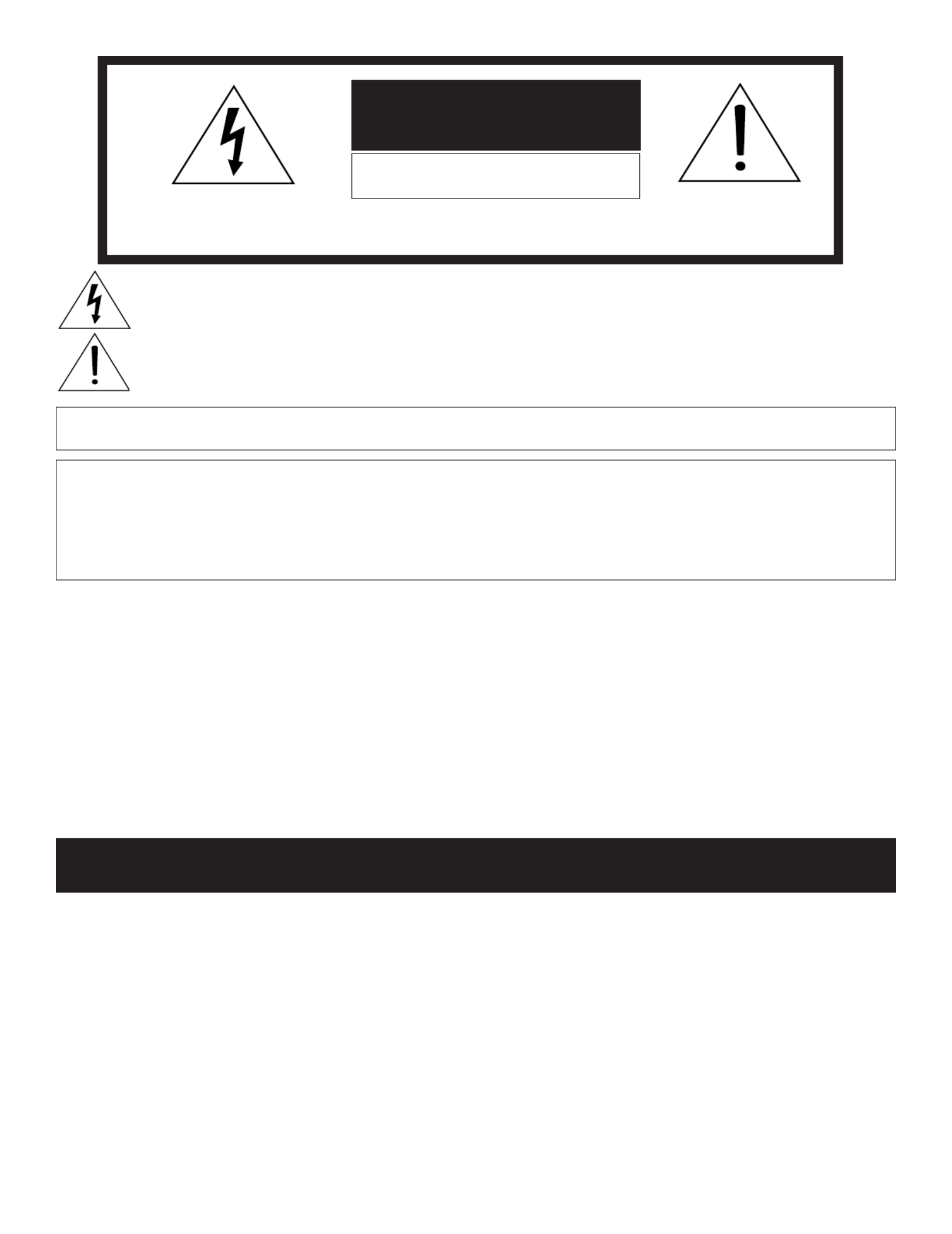
The lightning flash with arrowhead symbol within an equilateral triangle is intended to alert the user of
the presence of uninsulated “dangerous voltage” within the product’s enclosure that may be sufficient
magnitude to constitute a risk of electric shock.
The exclamation point within an equilateral triangle is intended to alert the user to the presence of important
operating and maintenance (servicing) instructions in the literature accompanying the appliance.
Note: This equipment has been tested and found to comply with the limits for a Class B digital device, pursuant to
part 15 of the FCC Rules. These limits are designed to provide reasonable protection against harmful interference in
a residential installation. This equipment generates, uses and can radiate radio frequency energy and, if not installed
and used in accordance with the instructions, may cause harmful interference to radio communications. However,
there is no guarantee that interference will not occur in a particular installation. If this equipment does cause harmful
interference to radio or television reception, which can be determined by turning the equipment off and on, the user
is encouraged to try to correct the interference by one or more of the following measures:
• Reorient or relocate the receiving antenna.
• Increase the separation between the equipment and the receiver.
• Connect the equipment into an outlet on a circuit different from that to which the receiver is connected.
• Consult the dealer or an experienced radio/TV technician for help.
Changes or modifications not expressly approved by Mitsubishi could cause harmful interference
and would void the user’s authority to operate this equipment.
WARNING: TO REDUCE THE RISK OF FIRE OR ELECTRIC SHOCK, DO NOT EXPOSE THIS APPLIANCE TO RAIN
OR MOISTURE.
CAUTION: TO PREVENT ELECTRIC SHOCK, MATCH WIDE BLADE OF PLUG TO WIDE SLOT, FULLY INSERT.
NOTE TO CATV SYSTEM INSTALLER: THIS REMINDER IS PROVIDED TO CALL THE CATV SYSTEM INSTALLER’S
ATTENTION TO ARTICLE 820-40 OF THE NEC THAT PROVIDES GUIDELINES FOR THE PROPER GROUNDING AND,
IN PARTICULAR, SPECIFIES THAT THE CABLE GROUND SHALL BE CONNECTED TO THE GROUNDING SYSTEM
OF THE BUILDING, AS CLOSE TO THE POINT OF CABLE ENTRY AS PRACTICAL.
CAUTION: To assure continued FCC compliance, the user must use a shielded video interface cable
with bonded ferrite cores at both ends.
C
C
C
CCA
A
A
AAUT
UT
UT
UTUTIO
IO
IO
IOION
N
N
NNCAUTION
RISK OF E
RISK OF E
RISK OF E
RISK OF ERISK OF ELECTRIC SHOCK
LECTRIC SHOCK
LECTRIC SHOCK
LECTRIC SHOCKLECTRIC SHOCKRISK OF ELECTRIC SHOCK
DO NOT OPEN
DO NOT OPEN
DO NOT OPEN
DO NOT OPENDO NOT OPENDO NOT OPEN
Warning: To avoid permanently imprinting a fixed image onto your TV screen, please do not display the same
stationary images on the screen for more than 15% of your total TV viewing in one week. Examples of stationary
images are letterbox top/bottom bars from DVD disc or other video sources, side bars when showing standard
TV pictures on widescreen TVs, stock market reports, video game patterns, black or bright Closed Caption
backgrounds, station logos, web sites or stationary computer images. Such patterns can unevenly age the picture
tubes causing permanent damage to the TV. Please see pages 12 and 54 for a detailed explanation.
CAUTION: TO REDUCE THE RISK OF ELECTRIC SHOCK, DO NOT REMOVE COVER (OR
BACK). NO USER SERVICEABLE PARTS INSIDE. REFER SERVICING TO QUALIFIED SERVICE
PERSONNEL.
This TV is very heavy! Exercise extreme care when moving TV as foreign material may become
embedded in the castor wheels which could damage wood or other delicate flooring.

Chapter 1 Television Overview
TV Accessories .....................................................8
Special Features ...................................................8
Front Control Panel ...............................................9
Back Panel .......................................................... 10
Important Notes ................................................... 12
Chapter 2 Connecting
External Devices
& NetCommand® Setup ...................................... 14
Wall Outlet Cable or Cable Box ........................... 15
Single Analog Antenna ......................................... 16
Separate UHF and VHF Antennas ....................... 16
VCR Video and Audio to an Antenna
or Wall Outlet Cable ............................................. 17
VCR Video and Audio to a Cable Box .................. 18
A/V Receiver or Stereo System .......................... 19
Satellite Receiver or Other Device
with S-Video ......................................................... 19
DVD Player with Component Video .................... 20
DVI Device ............................................................ 20
HDMI Device ........................................................ 21
External DTV Receiver with Component Video ... 21
IR Emitter NetCommand® ................................... 22
IEEE 1394 Devices ............................................... 23
IEEE 1394 Device Connection Styles .................. 24
CableCARD™ Definition and Initial
Screen Display ..................................................... 25
Helpful Hints ......................................................... 26
Chapter 3 NetCommand® Setup and Editing
NetCommand® Pre-Memorized Devices ............ 28
Remote Control Functions: Overview .................. 29
Remote Control Functions: Operation,
Care, Sleep Timer ................................................ 30
NetCommand® OnScreen Buttons ..................... 31
3D Graphical Menu System ..................... 32
NetCommand® Initial Setup ................................ 33
Edit NetCommand®
Adding an A/V Receiver ................................. 35
Adding Devices .............................................. 38
Changing, Deleting Devices,
Finish Screen ................................................. 42
Device Selection Menu ........................................ 43
Using the Device Menu Button to
Display Menus ...................................................... 44
Chapter 4 IEEE 1394 Devices and
NetCommand® Controlled Recordings
Adding IEEE 1394 Devices Automatically ............ 46
IEEE 1394 Devices Compatibility ......................... 48
Using the Guide Button to Display
ChannelView™ and Menus .................................. 49
NetCommand® Controlled Recordings .............. 50
Direct VCR Recording ......................................... 52
NetCommand® Controlled Peer-to-Peer
Connections ......................................................... 53
Important Notes ................................................... 54
Chapter 5 TV Menu Screen Operations
Main Menu Choices ............................................. 56
Setup Menu .......................................................... 57
NetCommand® Menu .......................................... 59
Antenna Menu ...................................................... 60
Time Menu ........................................................... 62
Captions Menu ..................................................... 63
V-Chip Lock Menu ............................................... 65
Audio Video Menu ................................................ 68
A/V Setting Descriptions ..................................... 69
Chapter 6 Special Features
Display Formats .................................................. 72
Operation of PIP and POP ................................... 74
Device Menu with NetCommand® ...................... 75
Appendix A: Bypassing the V-Chip Lock ............ 77
Appendix B: High Definition Input
Connection Compatibility .................................... 79
Appendix C: Remote Control
Programming Codes ............................................ 80
Appendix D: On-Screen Information
Displays ................................................................ 83
Appendix E: NetCommand® Specialized
Device Keys ......................................................... 84
Appendix F: Cleaning and Service ...................... 85
Appendix G: Diamond Shield™ Removal ............ 86
Appendix H: Cabinet Separation ........................ 88
Troubleshooting .................................................. 89
Additional Information .......................................... 93
Index ..................................................................... 94
Warranty ............................................................... 96
Contents

4
IMPORTANT SAFEGUARDS
Please read the following safeguards for your TV and retain for future reference. Always follow all
warnings and instructions marked on the television.
1. Read, Retain and Follow All Instructions
Read all safety and operating instructions before operating the TV. Retain the safety and operating instructions
for future reference. Follow all operating and use instructions.
2. Heed Warnings
Adhere to all warnings on the appliance and in the operating instructions.
3. Cleaning
Unplug the TV from the wall outlet before cleaning. Do not use liquid, abrasive, or aerosol cleaners. Cleaners
can permanently damage the cabinet and screen. Use a lightly dampened cloth for cleaning.
4. Attachments and Equipment
Never add any attachments and/or equipment without approval of the manufacturer as such additions may result
in the risk of fire, electric shock or other personal injury.
5. Water and Moisture
Do not use the TV where contact with or immersion in water is possible. Do not use near bath tubs, wash bowls,
kitchen sinks, laundry tubs, swimming pools, etc.
6. Accessories
Do not place the TV on an unstable cart, stand, tripod or table. The TV may fall, causing
serious injury to a child or adult and serious damage to the TV. Use only with a cart, stand,
tripod, bracket or table recommended by the manufacturer, or sold with the TV. Any
mounting of the TV should follow the manufacturer’s instructions, and should use mounting
accessories recommended by the manufacturer.
An appliance and cart combination should be moved with care. Quick stops, excessive force,
and uneven surfaces may cause the appliance and cart combination to overturn.
7. Ventilation
Slots and openings in the cabinet are provided for ventilation and to ensure reliable operation of the TV and to
protect it from overheating. Do not block these openings or allow them to be obstructed by placing the TV on a
bed, sofa, rug, or other similar surface. Nor should it be placed over a radiator or heat register. If the TV is to be
placed in a rack or bookcase, ensure that there is adequate ventilation and that the manufacturer’s instructions
have been adhered to.
8. Power Source
This TV should be operated only from the type of power source indicated on the marking label. If you are not sure
of the type of power supplied to your home, consult your appliance dealer or local power company.
9. Grounding or Polarization
This TV is equipped with a polarized alternating current line plug having one blade wider than the other. This plug
will fit into the power outlet only one way. If you are unable to insert the plug fully into the outlet, try reversing the
plug. If the plug should still fail to fit, contact your electrician to replace your obsolete outlet. Do not defeat the
safety purpose of the polarized plug.
10. Power-Cord Protection
Power-supply cords should be routed so that they are not likely to be walked on or pinched by items placed
upon or against them, paying particular attention to cords at plugs, convenience receptacles, and the point
where they exit from the TV.
11. Lightning
For added protection for this TV during a lightning storm, or when it is left unattended and unused for long
period of time, unplug it from the wall outlet and disconnect the antenna or cable system. This will prevent
damage to the TV due to lightning and power-line surges.
5
IMPORTANT SAFEGUARDS, cont’d.
12. Power Lines
An outside antenna system should not be located in the vicinity of overhead power lines or other electric light or
power circuits, or where it can fall into such power lines or circuits. When installing an outside antenna system,
extreme care should be taken to keep from touching such power lines or circuits as contact with them might be
fatal.
13. Overloading
Do not overload wall outlets and extension cords as this can result in a risk of fire or electric shock.
14. Object and Liquid Entry
Never push objects of any kind into this TV through openings as they may touch dangerous voltage points or
short-out parts that could result in fire or electric shock. Never spill liquid of any kind on or into the TV.
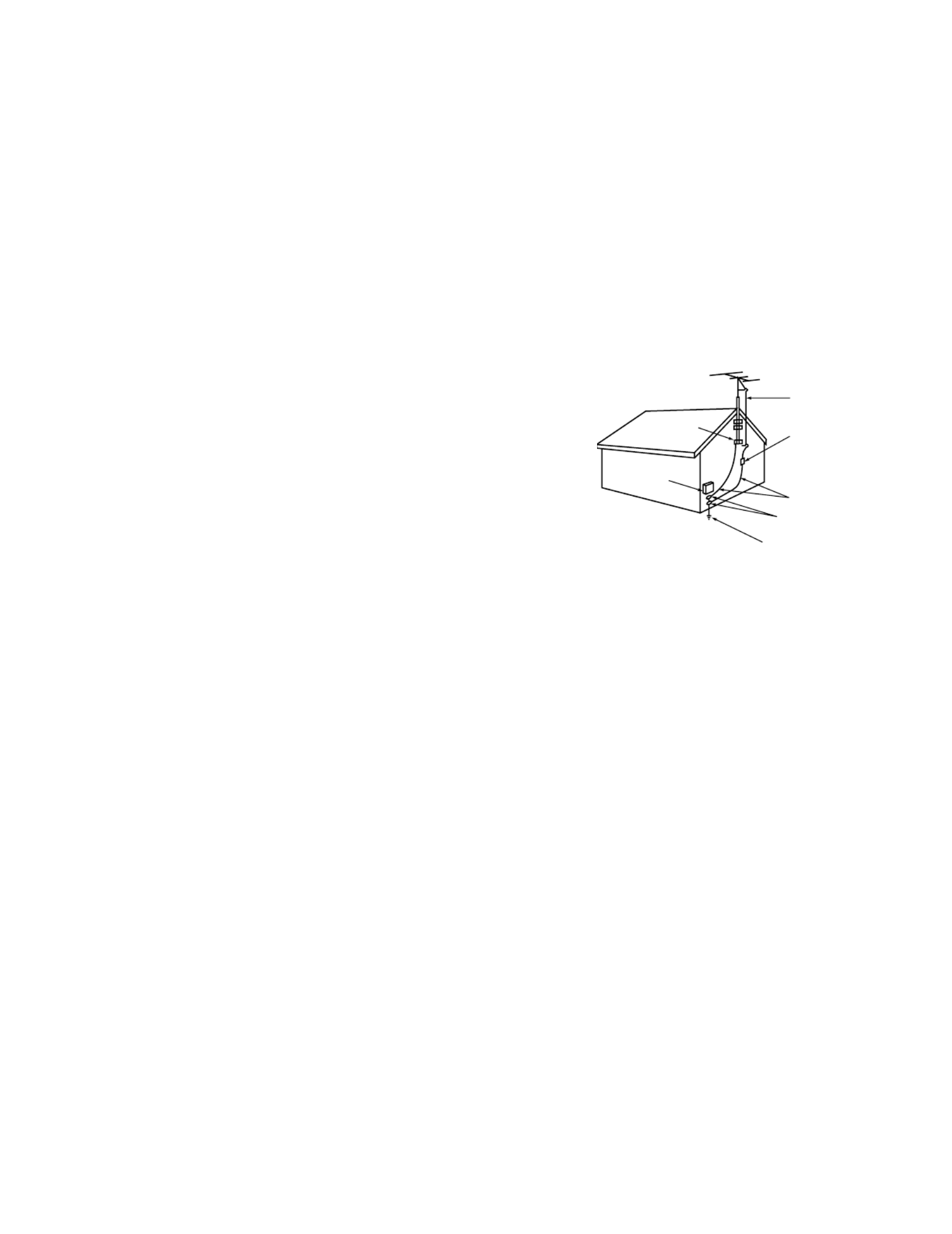
15. Outdoor Antenna Grounding
If an outside antenna or cable system is connected to the TV, be
sure the antenna or cable system is grounded so as to provide some
protection against voltage surges and built-up static charges.
Article 810 of the National Electric Code, ANSI/NFPA No. 70-2002,
provides information with respect to proper grounding of the
mast and supporting structure, grounding of the lead in wire to an
antenna discharge unit, size of grounding conductors, location of
antenna discharge unit, connection to grounding electrodes, and
requirements for the grounding electrode.
16. Servicing
Do not attempt to service this TV yourself as opening or removing covers may expose you to dangerous voltage
or other hazards. Refer all servicing to qualified service personnel.
17. Damage Requiring Service
Unplug the TV from the wall outlet and refer servicing to qualified service personnel under the following
conditions:
(a) When the power-supply cord or plug is damaged.
(b) If liquid has been spilled, or objects have fallen into the TV.
(c) If the TV has been exposed to rain or water.
(d) If the TV does not operate normally by following the operating instructions, adjust only those controls that are
covered by the operating instructions as an improper adjustment of other controls may result in damage and
will often require extensive work by a qualified technician to restore the TV to its normal operation.
(e) If the TV has been dropped or the cabinet has been damaged.
(f) When the TV exhibits a distinct change in performance - this indicates a need for service.
18. Replacement Parts
When replacement parts are required, be sure the service technician has used replacement parts specified by
the manufacturer or have the same characteristics as the original part. Unauthorized substitutions may result in
fire, electric shock or other hazards.
19. Safety Check
Upon completion of any service or repair to the TV, ask the service technician to perform safety checks to
determine that the TV is in safe operating condition.
20. Heat
The product should be situated away from heat sources such as radiators, heat registers, stoves, or other
products (including amplifiers) that produce heat.
ANTENNA
LEAD IN WIRE
ANTENNA
DISCHARGE UNIT
(NEC SECTION 810-20)
GROUNDING
CONDUCTORS
(NEC SECTION 810-21)
GROUND CLAMPS
POWER SERVICE GROUNDING
ELECTRODE SYSTEM
(NEC ART 250, PART H)
GROUND CLAMP
ELECTRIC
SERVICE
EQUIPMENT
NEC — NATIONAL ELECTRICAL CODE
EXAMPLE OF ANTENNA GROUNDING

6
Our Thanks...
Thank you for choosing Mitsubishi as your premier Home Entertainment provider.
This Owner’s Guide describes the features and functions of your Mitsubishi
widescreen, high definition TV. We urge you to examine this Owner’s Guide to
become familiar with the innovative features and operations this unique television
offers.
The very core of our corporate philosophy is to provide our customers with the
very best. Our development team at Mitsubishi has worked to provide you with
a television that defines “state-of-the-art,” with the capability to meet your needs
now and in the future.
Whether this is your first Mitsubishi electronic product, or an addition to your
Mitsubishi collection, we believe you and your family will continue to enjoy your
Mitsubishi home theater for many years.
Thank you,
Mitsubishi Digital Electronics America, Inc.

Chapter . . . 1
Television Overview
TV Accessories ............................................................................8
Special Features ..........................................................................8
Front Control Panel ......................................................................9
Back Panel .................................................................................10
Important Notes .........................................................................12

8
POWER
HOME
PAUSEREC
FF/FWDREW/REV PLAY
ST OP
3
6
9
QV
VOLUME
INFO
EXCH
ENT ER
TV MENU DEVICE
MENU
V-CHIP
FORMAT
PIP CH
1
7
SQV
4
DEVICE
SLEEP
VIDEO
AUDIO
MUTE
2
5
8
0
CHANNEL
ADJUST
PIP /POP
PIP DEVICE
CANCEL
TV AUDIO
CABLE/DBS/DTV DVD
VCR
GUIDE
SUB
CONNECT
TV Accessories
Please take a moment to review the following list of
items to ensure that you have received everything
including:
AAA
AAA
1. Remote Control
2. Two AAA Batteries
4. One Quadruple IR Emitter Cable
(allows NetCommand to control other
devices)
3. One Digital Audio Cable (sends
the audio of digital channels to a
digital A/V receiver).
5. Product Registration Card (not pictured)
6. Owner’s Guide (not pictured)
7. Quick Reference Card (not pictured)
Special Features
Your new widescreen High Definition television has
many special features that make it the perfect center
of your home entertainment system, including:
Fully Integrated HDTV
This HDTV can receive all approved terrestrial
broadcast digital signals, non-scrambled digital cable
signals, terrestrial analog signals and non-scrambled
analog cable signals that use a standard offset carrier
system. Your TV will display all signals as 1080i True
HDTV™.
Digital Cable Ready (CableCARD™)
This HDTV is “Plug-and-Play” ready. It can descramble
a cable provider’s one-way digital signals with the use
of a CableCARD security module. The CableCARD is
used in place of a traditional cable box to access digital
cable programming (including high definition). Contact
your local cable provider for availability information and
service details.
NetCommand® Control System
This HDTV offers a new level of networking to
combine selected older products with new and future
digital products. NetCommand supports IEEE 1394
connections with Audio Video Control system (AV/C),
5C copy protection and IR control of selected older
products such as VCRs, DVD players, cable boxes or
satellite receivers. NetCommand includes the ability to
learn remote control signals directly from many devices,
allowing you to customize the NetCommand system in
a way that works best for your viewing.
16:9 Widescreen Picture Format
Enjoy a full theatrical experience in the comfort of your
home. View pictures as film directors intended them.
Digital TV broadcasts, DVDs and newer video game
consoles support this widescreen format.

9
Front Control Panel
SYSTEM RESET
If the TV will not respond to either the remote control or the front panel controls and/or will not power Off, press the
SYSTEM RESET button with a pointed item like the end point of a paperclip. The TV will turn Off and the TIMER
light will flash quickly for about one minute. When the TIMER light stops flashing, you may turn on the TV again.
Changes you made the last time the TV was On before you used the SYSTEM RESET button may be lost, however,
the changes you made previously are not lost.
POWER/TIMER Indicator
The green light is a multi-function indicator. This light will flash rapidly for about one minute each time the TV is
plugged into the wall electrical outlet, when power is restored after a power failure, or using the SYSTEM RESET
button. Do not attempt to turn on the TV again during this period. Wait for the flashing to stop and the light to
turn off, before attempting to turn the TV on. While the TV is powered on, the light illuminates steadily. If the TV
has been programmed to turn on automatically using the Timer feature, this light will flash slowly when the TV is
powered off.
A/V RESET Procedure
There may be times when you wish to reset the A/V (Audio and Video) settings back to the factory defaults. To do
this for an individual setting, use the Audio or Video remote control button. To return all of the settings at once,
press GUIDE and FORMAT on the front panel at the same time, or use the A/V Memory Reset selection on the
AudioVideo menu (page 68).
INPUT 3
This input can be used for convenient connection of a camcorder or other video device to the TV. If you connect to
the S-VIDEO terminal, the VIDEO terminal is deactivated. The VIDEO terminal is available when there is no S-Video
connection.
IEEE 1394
This IEEE 1394 (FireWire®) input/output allows for temporary connection of IEEE 1394 devices such as MPEG 2
camcorders or compatible hard disc drives to the front of the TV. This connection works the same way as the two rear
IEEE 1394 connections.
Except for SYSTEM RESET and TIMER, all of the buttons on the Front Control Panel (highlighted in gray) are
duplicated on the remote control. The top row of labels show the control functions when there are no TV menus
displayed on the screen. The bottom row of labels show the control functions when the TV menus are displayed on
the screen or when a special function has been activated. See Remote Control Overview page 29, for further details
on the functions of these buttons. TIMER is also accessible through the menu screens. Pressing MENU on the front
panel will display the TV menu.
DEVICE
CANCELMENUENTER
MENUFORMAT
CHVOL
POWER
SYSTEM
RESET
TIMER ADJUST
ADJUST
Front Panel WS-55517, WS-65517, WS-73517
GUIDE
INPUT-3
S-VIDEO VIDEO L-AUDIO-R
IEEE 1394

10
SERVICE WARNING
X-RAY PRECAUTION:
THIS PRODUCT
I N C L U D E S C R I T I C A L M E C H A N I C A L
AND E LE CT R IC A L PA RT S WH IC H AR E
E S SE N T I AL F OR X -R A DI AT I O N S AF E T Y.
F O R C O N T I NU E D S A F E T Y R E P L A CE
C R I T I C A L C O M P O N E N T S I N D I C AT E D
IN T HE S E RV IC E MAN UA L ON LY WI T H
E X A CT R E P LA C E ME N T PA R T S G IV E N
IN THE PARTS LIST. REFER TO SERVICE
MANUAL FOR OPERATING HIGH VOLTAGE AT
MIN IMUM B RIG HT NE SS, ME ASURE MEN T
PROC ED U RES AND PROP ER S E R VICE
ADJUSTMENTS.
WARNING:
HANDLE WITH CARE. HIGH
VACUUM PICTURE TUBE IS DANGEROUS
T O HA NDLE. RE FER S ERV ICIN G T O
Q UA L IF I E D S E R V IC E P E R S O N NE L .
REPLACE WITH A TUBE OF THE SAME
TYPE NUMBER FOR CONTINUED SAFETY.
CAUTION:
TO MEASURE SECOND
ANODE VOLTAGE USE A HIGH VOLTAGE
METER CONNECTED FROM ANODE LEAD
TO CHASSIS ONLY. DISCHARGE HIGH
VOLTAGE TO CHASSIS ONLY, NOT TO
EXTERNAL GROUND.
IR EMITTER
NetCommand R
DIGITAL
SERVICE
PORT
IEEE1394
INPUT/OUTPUT AUDIO
ANT-2
AUX
ANT-1
MAIN
CableCARDTM SLOT
– –(DT V/CABLE /VHF/UHF)
S-VIDEO
VIDEO
AUDIO-
LEFT/
(MONO)
AUDIO-
RIGHT
INPUT MONITOR OUTPUT
AUDIO 2
AUDIO/VIDEO 1
1 2
COMPONENT
YPbPr (480i/480p/1080i)
21
Y
Pb
Pr
AUDIO-
LEFT/
(MONO)
AUDIO-
RIGHT
DVI
Digital Video
Digital Audio
Analog Audio
11.
1. 2. 3. 4. 5. 6. 7.
8.
9.
10.
Back Panel
1. IEEE-1394 Input/Output
Use these jacks to connect the TV to external IEEE 1394 digital products by means of a single cable. There are
two jacks on the back panel for all models. For WS-55517, WS-65517 and WS-73517 there is an additional jack on
the front panel. IEEE 1394 connections provide a high degree of flexibility when connecting your NetCommand®
controlled system. Detailed information regarding IEEE 1394 connection requirements are in Chapter 4.
2. Antenna (ANT-1 MAIN, ANT-2 AUX)
ANT-1 MAIN and ANT-2 AUX can each receive both digital/analog over-the-air channels from a VHF/UHF antenna or
non-scrambled digital/analog cable channels.
Your primary viewing signal source should be connected to ANT-1 MAIN. ANT-1 MAIN must be used to view
premium subscription cable TV service authorized by the CableCARD™ access card. The CableCARD access card
is provided by your local cable company. ANT-2 AUX can continue to receive over-the-air or non-scrambled cable
signals.
3. Digital Audio Output
This output will automatically send Dolby® Digital audio from digital channels and IEEE 1394 devices to a digital
Audio/Video receiver. Connect this output to the A/V receiver’s coaxial digital audio input. This output will
automatically turn off when viewing an analog channel or device. HDMI digital audio signals are not sent by this
output. Use Monitor Output Audio 2 to send analog signals and HDMI audio signals to your A/V receiver.
Some digital cable channels send MPEG-1 digital audio instead of Dolby Digital, however, not all A/V receivers can
decode MPEG-1 digital audio. This can cause the A/V receivers to produce a loud noise that can damage speakers.
For this reason, the TV will automatically turn off the digital audio output when tuned to a channel or device that has
MPEG-1 digital audio and send it to the A/V receiver as analog left and right audio from Monitor Output.

11
4. CableCARD™ Slot
The CableCARD access card provided by your cable TV service provider is inserted into this slot. CableCARD is a
nationwide standard system that allows your local cable TV provider to supply you with an access card customized
to your account. This card allows the TV to receive, decode and unscramble the premium digital channels included
in your cable TV subscription without the use of a cable box. It also allows your cable provider to automatically
update and change your subscription. See pages 15, 25, and 44 for additional CableCARD information and
activation instructions.
If your cable company is not currently offering CableCARD, you will need to use an external cable box.
5. HDMI™ or DVI Devices
The HDMI™ interface supports uncompressed standard, enhanced and high definition digital video formats. This
interface also supports existing digital multi-channel audio formats. The HDMI input supports both video and
audio using one single cable. Use this input to connect to EIA/CEA-861 compliant devices such as a high definition
receiver or DVD player. This input supports the 480i, 480p and 1080i video formats. It is not intended for use with
personal computers or devices outputting video signals with computer resolutions. Supported audio signal is PCM
linear stereo. Multi-channel surround sound is not supported.
This input can also be used as a DVI connection with separate analog audio inputs (see DVI Analog Audio, below).
An optional HDMI-to-DVI adaptor will be necessary to make this connection and can be purchased from your
local electronics retailer. When using the optional HDMI-to-DVI adapter, the DVI analog audio inputs on your TV
allow you to receive left and right audio from your DVI device. This input is HDCP (High-Bandwidth Digital Copy
Protection) compliant.
6. DVI Analog Audio
Unlike HDMI, DVI does not carry audio information on the same cable. Use these analog stereo audio inputs when
using the HDMI input with a device that outputs DVI instead of HDMI.
7. Component Inputs 1-2 YPbPr(480i/480p/1080i)
These inputs can be used for the connection of devices with component video outputs, such as a DVD player,
external HDTV receiver or compatible video game system. Please see Appendix B for signal compatibility.
8. IR Output-NetCommand®
Two jacks are provided for connecting IR emitters. IR Emitters connected to these jacks are used by the TV’s
NetCommand system to control external analog devices such as VCRs, DVDs, cable boxes, satellite and audio
receivers.
9. Monitor Output (Audio/Video 1, Audio 2)
The Monitor Output sends the TV audio and video signals from the antennas or Inputs 1-3 to an A/V Receiver or
other analog A/V equipment such as a VCR. Digital channels and IEEE 1394 signals will be down converted to
analog signals compatible with traditional analog VCRs. There will be no video signals from digital channels or IEEE
1394 signals that have copy restrictions. There will be no video signals from Monitor Outputs when viewing the
Component 1 & 2 inputs or the HDMI input
Monitor Output Audio/Video 1 should be connected to a VCR for recording. Monitor Output Audio 2 should be
connected to your A/V Receiver for home theater surround sound.
10. Inputs 1-2
These inputs can be used for the connection of a VCR, Super VHS (S-VHS) VCR, DVD player, standard satellite
receiver or other A/V device to the TV. Please note that if you connect to the S-VIDEO terminal, the VIDEO terminal
is deactivated. The VIDEO terminal is available when there is no S-Video connection.
11. SERVICE PORT
This input is for use by Authorized Mitsubishi Servicers only.
Back Panel, continued
Termékspecifikációk
| Márka: | Mitsubishi |
| Kategória: | Televíziók |
| Modell: | WS-65517 |
Szüksége van segítségre?
Ha segítségre van szüksége Mitsubishi WS-65517, tegyen fel kérdést alább, és más felhasználók válaszolnak Önnek
Útmutatók Televíziók Mitsubishi

10 Július 2024
7 Július 2024
6 Július 2024
4 Július 2024
1 Július 2024
Útmutatók Televíziók
- Televíziók Samsung
- Televíziók Sony
- Televíziók LG
- Televíziók Philips
- Televíziók Panasonic
- Televíziók JVC
- Televíziók Sharp
- Televíziók Clatronic
- Televíziók Hitachi
- Televíziók Daewoo
- Televíziók AKAI
- Televíziók Sanyo
- Televíziók Sylvania
- Televíziók Marquant
- Televíziók Superior
- Televíziók EKO
Legújabb útmutatók Televíziók

16 Január 2025
14 Január 2025
16 Október 2024
16 Október 2024

16 Október 2024
16 Október 2024
15 Október 2024

14 Október 2024
13 Október 2024

13 Október 2024