Használati útmutató Mitsubishi VS-55609
Mitsubishi
Televíziók
VS-55609
Olvassa el alább 📖 a magyar nyelvű használati útmutatót Mitsubishi VS-55609 (64 oldal) a Televíziók kategóriában. Ezt az útmutatót 10 ember találta hasznosnak és 2 felhasználó értékelte átlagosan 4.5 csillagra
Oldal 1/64
Projection Television Models
VS-45609, VS-50609, VS-55609,
VS-60609, VS-60719, VS-70709
visit our website at
w w w. m i t su b i s hi - t v. c om
®

CAUTION: TO REDUCE THE RISK OF ELEC- TRIC SHOCK,
DO NOT REMOVE COVER (OR
BACK).
NO USER SERVICEABLE
PARTS INSIDE.
REFER SERVICING TO QUALIFIED SERVICE PERSONNEL.
CAUTION
RISK OF ELECTRIC SHOCK
DO NOT OPEN
The lightning ash with arrowhead symbol within an equilateral triangle is intended to alert the
user of the presence of uninsulated “dangerous voltage” within the product’s enclosure that
may be sufcient magnitude to constitute a risk of electric shock.
The exclamation point within an equilateral triangle is intended to alert the user to the
presence of important operating and maintenance (servicing) instructions in the literature
accompanying the appliance.
Warning: To avoid permanently imprinting a xed image onto your TV screen, please do not display the
same stationary images on the screen for more that 15% of your total TV viewing in one week. Examples
of stationary images are letterbox top/bottom bars from DVD disk or other video sources, side bars when
showing standard TV pictures on widescreen TV’s, stock market reports, video game patterns, station
logos, web sites or stationary computer images. Such patterns can unevenly age the picture tubes causing
permanent damage to the TV. Please see pages 21 and 52 for a detailed explanation.
Note: This equipment has been tested and found to comply with the limits for a Class B digital device,
pursuant to part 15 of the FCC Rules. These limits are designed to provide reasonable protection
against harmful interference in a residential installation. This equipment generates, uses and can radiate
radio frequency energy and, if not installed and used in accordance with the instructions, may cause
harmful interference to radio communications. However, there is no guarantee that interference will not
occur in a particular installation. If this equipment does cause harmful interference to radio or television
reception, which can be determined by turning the equipment off and on, the user is encouraged to try
to correct the interference by one or more of the following measures:
• Reorient or relocate the receiving antenna.
• Increase the separation between the equipment and the receiver.
• Connect the equipment into an outlet on a circuit different from that to which the receiver is
connected.
• Consult the dealer or an experienced radio/TV technician for help.
Changes or modications not expressly approved by Mitsubishi could void the user’s authority to operate
this equipment.
WARNING:
TO REDUCE THE RISK OF FIRE OR ELECTRIC SHOCK, DO NOT EXPOSE THIS APPLIANCE TO RAIN
OR MOISTURE.
CAUTION:
TO PREVENT ELECTRIC SHOCK, MATCH WIDE BLADE OF PLUG TO WIDE SLOT, FULLY INSERT.
NOTE TO CATV SYSTEM INSTALLER:
THIS REMINDER IS PROVIDED TO CALL THE CATV SYSTEM INSTALLER’S ATTENTION TO ARTICLE
820-40 OF THE NEC THAT PROVIDES GUIDELINES FOR THE PROPER GROUNDING AND, IN PAR-
TICULAR, SPECIFIES THAT THE CABLE GROUND SHALL BE CONNECTED TO THE GROUNDING
SYSTEM OF THE BUILDING, AS CLOSE TO THE POINT OF CABLE ENTRY AS PRACTICAL.

3
3
O
P
E
R
A
T
I
O
N
S
E
T
U
P
I
N
S
T
A
L
L
A
T
I
O
N
T
H
A
N
K
Y
O
U
Table of Contents
Table of Contents
IMPORTANT SAFEGUARDS ............................................................................4-5
Thank You Letter ...............................................................................................................................................8
Unpacking Your New TV...................................................................................................................................9
Features ...........................................................................................................................................................9
Front Control Panel Functions ......................................................................................................................12
Back Panel Functions..................................................................................................................................... 13
How Connections Affect:
PIP ..............................................................................................................................................................14
System 4 Home Theater IR Control....................................................................................................14-15
Connecting to Your New Mitsubishi Bigscreen:
Antenna or Wall Outlet Cable ..................................................................................................................16
Cable Box................................................................................................................................................... 16
VCR ......................................................................................................................................................... 17
Audio Receiver ..........................................................................................................................................18
DVD Player .................................................................................................................................................19
S-Video Device.......................................................................................................................................... 19
System 4 Home Theater IR Control.........................................................................................................20
IMPORTANT NOTES .......................................................................................................................................21
Programming the Remote Control: To Control Other A/V Products.................................................. 24-25
Programming the Remote Control: To Activate the System 4 Home Theater IR Control ................ 26-27
on-screen menu system ......................................................................................................................28
Menu Screens (Overview).................................................................................................................. 39-30
Setup Menu................................................................................................................................................31
Memorize Channels ............................................................................................................................31
Clock.....................................................................................................................................................31
Language .............................................................................................................................................31
Captions Menu ..........................................................................................................................................32
V-Chip Parent Lock Menu .................................................................................................................. 33-35
Channel Edit Menu....................................................................................................................................35
Advanced Features Menu ........................................................................................................................37
Timer.....................................................................................................................................................37
Convergence........................................................................................................................................38
Advanced Convergence .....................................................................................................................39
Special Features..................................................................................................................................39
Audio/Video Serrings Menu .............................................................................................................. 40-41
A/V Setting Descriptions ................................................................................................................... 42-43
Remote Control Functions....................................................................................................................... 46-51
Overview ....................................................................................................................................................46
Care and Operation ..................................................................................................................................47
Channel Selection.....................................................................................................................................48
Sleep Timer................................................................................................................................................48
System 4 Home Theater IR Control................................................................................................... 48-49
Special Functions .....................................................................................................................................50
Operation of PIP and POP........................................................................................................................51
IMPORTANT NOTES .......................................................................................................................................52
Appendix A: Bypassing the V-Chip Lock ...........................................................................................................55
Appendix B: High Resolution Input Connection Compatibility .......................................................................57
Appendix C: Remote Control Programing Codes .............................................................................................58
Appendix D: Cleaning and Service .....................................................................................................................59
Appendix E: Troubleshooting..............................................................................................................................60
Index 61-62.................................................................................................................................................................
Mitsubishi Projection TV Limited Warranty .......................................................................................................63

4
4
Important Safeguards
IMPORTANT SAFEGUARDS
Please read the following safeguards for your TV and retain for future reference.
Always follow all warnings and instructions marked on the television.
1. Read, Retain and Follow All Instructions
Read all safety and operating instructions before operating the TV. Retain the safety and operating instructions
for future reference. Follow all operating and use instructions.
2. Heed Warnings
Adhere to all warnings on the appliance and in the operating instructions.
3. Cleaning
Unplug the TV from the wall outlet before cleaning. Do not use liquid, abrasive, or aerosol cleaners. Cleaners
can permanently damage the cabinet and screen. Use a lightly dampened cloth for cleaning.
4. Attachments and Equipment
Never add any attachments and/or equipment without approval of the manufacturer as such additions may
result in the risk of re, electric shock or other personal injury.
5. Water and Moisture
Do not use the TV where contact with or immersion in water is possible. Do not use near bath tubs, wash
bowls, kitchen sinks, laundry tubs, swimming pools, etc.
6. Accessories
Do not place the TV on an unstable cart, stand, tripod, or table. The TV may fall, causing
serious injury to a child or adult and serious damage to the TV. Use only with a cart, stand,
tripod, bracket, or table recommended by the manufacturer, or sold with the TV. Any mounting
of the TV should follow the manufacturer’s instructions, and should use mounting accessories
recommended by the manufacturer.
An appliance and cart combination should be moved with care. Quick stops, excessive force,
and uneven surfaces may cause the appliance and cart combination to overturn.
7. Ventilation
Slots and openings in the cabinet are provided for ventilation and to ensure reliable operation of the TV and
to protect it from overheating. Do not block these openings or allow them to be obstructed by placing the TV
on a bed, sofa, rug, or other similar surface. Nor should it be placed over a radiator or heat register. If the
TV is to be placed in a rack or bookcase, ensure that there is adequate ventilation and that the manufacturer’s
instructions have been adhered to.
8. Power Source
This TV should be operated only from the type of power source indicated on the marking label. If you are not
sure of the type of power supplied to your home, consult your appliance dealer or local power company.
9. Grounding or Polarization
This TV is equipped with a polarized alternating current line plug having one blade wider than the other. This
plug will t into the power outlet only one way. If you are unable to insert the plug fully into the outlet, try
reversing the plug. If the plug should still fail to t, contact your electrician to replace your obsolete outlet. Do
not defeat the safety purpose of the polarized plug.
10. Power-Cord Protection
Power-supply cords should be routed so that they are not likely to be walked on or pinched by items placed
upon or against them, paying particular attention to cords at plugs, convenience receptacles, and the point
where they exit from the TV.
11. Lightning
For added protection for this TV during a lightning storm, or when it is left unattended and unused for long
periods of time, unplug it from the wall outlet and disconnect the antenna or cable system. This will prevent
damage to the TV due to lightning and power-line surges.

5
5
Important Safeguards
IMPORTANT SAFEGUARDS Continued
12. Power Lines
An outside antenna system should not be located in the vicinity of overhead power lines or other electric light
or power circuits, or where it can fall into such power lines or circuits. When installing an outside antenna
system, extreme care should be taken to keep from touching such power lines or circuits as contact with
them might be fatal.
13. Overloading
Do not overload wall outlets and extension cords as this can result in a risk of re or electric shock.
14. Object and Liquid Entry
Never push objects of any kind into this TV through openings as they may touch dangerous voltage points or
short-out parts that could result in re or electric shock. Never spill liquid of any kind on or into the TV.
15. Outdoor Antenna Grounding
If an outside antenna or cable system is connected to the TV, be
sure the antenna or cable system is grounded so as to provide
some protection against voltage surges and built-up static charges.
Section 810 of the National Electric Code, ANSI/NFPA No.
70-1984, provides information with respect to proper grounding of
the mast and supporting structure, grounding of the lead in wire to
an antenna discharge unit, size of grounding conductors, location
of antenna discharge unit, connection to grounding electrodes,
and requirements for the grounding electrode.
16. Servicing
Do not attempt to service this TV yourself as opening or removing covers may expose you to dangerous
voltage or other hazards. Refer all servicing to qualied service personnel.
17. Damage Requiring Service
Unplug the TV from the wall outlet and refer servicing to qualied service personnel under the following
conditions:
(a) When the power-supply cord or plug is damaged.
(b) If liquid has been spilled, or objects have fallen into the TV.
(c) If the TV has been exposed to rain or water.
(d) If the TV does not operate normally by following the operating instructions, adjust only those controls that
are covered by the operating instructions as an improper adjustment of other controls may result in damage
and will often require extensive work by a qualied technician to restore the TV to its normal operation.
(e) If the TV has been dropped or the cabinet has been damaged.
(f) When the TV exhibits a distinct change in performance - this indicates a need for service.
18. Replacement Parts
When replacement parts are required, be sure the service technician has used replacement parts specied
by the manufacturer or have the same characteristics as the original part. Unauthorized substitutions may
result in re, electric shock or other hazards.
19. Safety Check
Upon completion of any service or repair to the TV, ask the service technician to perform safety checks to
determine that the TV is in safe operating condition.
20. Heat
The product should be situated away from heat sources such as radiators, heat registers, stoves, or other
products (including ampliers) that produce heat.
ANTENNA
LEAD IN WIRE
ANTENNA
DISCHARGE UNIT
(NEC SECTION 810-20)
GROUNDING
CONDUCTORS
(NEC SECTION 810-21)
GROUND CLAMPS
POWER SERVICE GROUNDING
ELECTRODE SYSTEM
(NEC ART 250 PART H)
GROUND CLAMP
ELECTRIC
SERVICE
EQUIPMENT
NEC — NATIONAL ELECTRICAL CODE
EXAMPLE OF ANTENNA GROUNDING
As an ENERGY STAR partner, Mitsubishi Digital Electronics America, Inc. has determined that this product meets
the ENERGY STAR guidelines for energy efciency. This product can save energy. Saving energy reduces air
pollution and lowers utility bills.

If you have questions regarding your television, call
Consumer Relations
at (800) 332-2119, or email us at
MDE Aser v ice@bi gsc reen. mea. com
To order replacement or additional remote controls or owner’s
guides
call (800) 553-7278
or
visit our website at w ww.mit sub ishi -tv.c om

7
7
Thank You
Thank You Letter ............................8
Unpacking Your New TV .................9
Features............................................9

8
8
Part I: Thank You
Thank You Letter
A Note of Thanks from Mitsubishi...
Thank you for choosing Mitsubishi as your premier home
entertainment partner. The development team at Mitsubishi
understands that our customers are not the average people:
they demand and expect the very best. Hence, countless
hours have been invested to produce a sophisticated product
that we hope will meet all of your expectations.
Whether this is your rst Mitsubishi consumer electronic
product or simply an addition to your growing Mitsubishi
family, we hope that this television will bring you and your
family many hours of joy. We are delighted that you chose
such a technically advanced product. We know you will not
be disappointed.

U nlike typical television
manufacturers, we have based our
primary design and engineering
capabilities in North America at our
California headquarters. As a result,
the engineers who design our television
products live in the same communities as our
customers. They know how our customers
think and what their goals and desires
are. They know that today’s consumer has
never been more sophisticated and that the
way to reach that consumer is to deliver
technically advanced products at prices that
our competition simply can’t match.

11
11
Installation
Front Control Panel Functions .....12
Back Panel Functions ...................13
How Connections Affect:
PIP ..............................................14
System 4 Home Theater
IR Control ..............................14-15
Connecting to Your New Mitsubishi
Bigscreen:
Antenna or Wall Outlet Cable ...16
Cable Box ...................................16
VCR .............................................17
Audio Receiver...........................18
DVD Player..................................19
S-Video Device...........................19
System 4 Home Theater
IR Control ...................................20
IMPORTANT NOTES .....................21
VS-60719 & VS-70709
VS-60719 & VS-70709

12
12
Part II: Installation
Front Control Panel Functions
Front Control Panel
Many remote control buttons are duplicated on the front control panel. These buttons are
shaded in gures 1 and 2. Please see Remote Control Functions, pages 46-51, for an
explanation of their functions. You may temporarily deactivate the buttons on the front
control panel with the Front Button Lock feature, see Front Button Lock, page 39.
TIMER
or
TIMER
Timer
During normal operation, when the TV is set to turn on at a specic time, the green timer
light will blink while the TV is off. Please see Timer, page 37, for timer setup instructions.
A/V RESET
A/V Reset
Press this button to reset the A/V memory on all six inputs to the factory default settings.
To reset each input individually, see , page 40.A/V Memory Reset
S-VIDEO VIDEO L-AUDIO-R
or
S-VIDEO
VIDEO
(MONO)
AUDIO R
INPUT-3
L
Input 3
This input can be used for convenient connection of a camcorder or other video device to
the TV. Please note that if you connect to the S-VIDEO terminal, the VIDEO terminal is
deactivated. The VIDEO terminal is active when there is no S-Video connection.
Figure 1. Front Control Panel for models VS-45609, VS-50609, VS-55609, and VS-60719.
TIMER POWER VOL
CH
ENTER
MENU A/V RESET INPUT
ADJUST ADJUST CANCEL MENU
INPUT-3
S-VIDEO VIDEO L-AUDIO-R
ENTER
S-VIDEO
VIDEO
(MONO)
AUDIO R
INPUT-3
L
TIMER
A/V RESET
ADJUST
VOL
CHANNEL
POWER
CANCEL
ENTERMENU
INPUT
Figure 2. Front Control Panel for model VS-70709.
The Front Button Lock can be disabled
from the Front Control Panel by depress-
ing the MENU button for 8 seconds.
When successful, the message “Front
Button Lock Disabled” will display on
the screen.
13
13
ANT-A
IR EMITTER HOME THEATER
S-VIDEO
COMPONENT
L
(MONO)
R
ANT -B
CABLE
LOOP-OUT
INPUT INPUT OUTPUT
FIXED/
VARIABLE
21
VHF/UHF
(75 OHMS)
V
I
D
E
O
A
U
D
I
O
TUNER/
MONITOR
L
R
Y
Pb
DVD
(YPrPb) AUDIO
Pr
Part II: Installation
Back Panel Functions
Back Panel
1
2
3
4
5
1
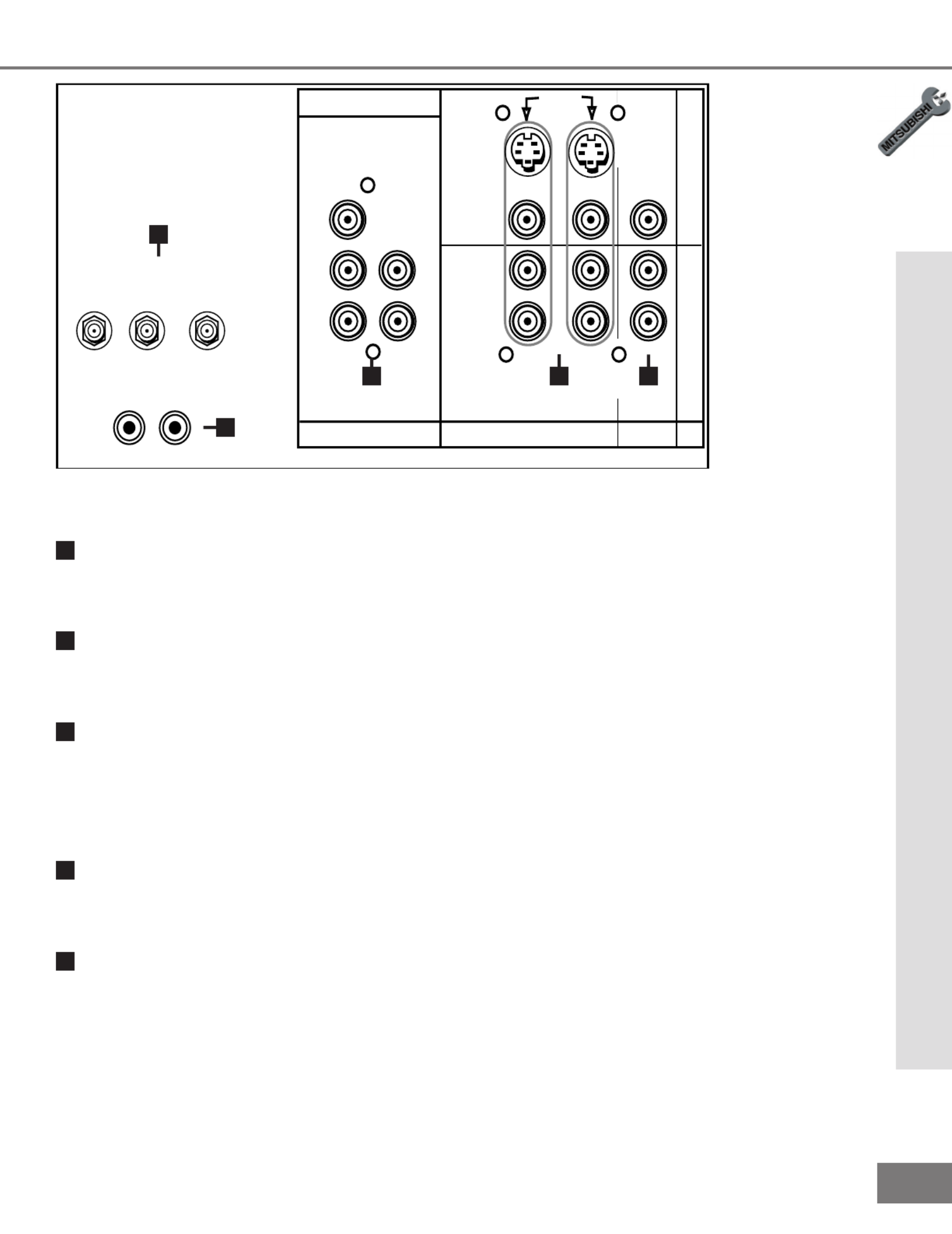
Antenna (ANT-A, CABLE LOOP-OUT, ANT-B)
ANT-A and ANT-B receive signals from VHF/UHF antennas or a cable system. LOOP OUT
sends the ANT-A signal out to another component, such as a cable box or VCR.
2
Component Input
This input can be used for the connection of A/V equipment with component video outputs,
such as a DVD player. Please see , page 57, for signal compatibility.Appendix B
3
Inputs 1-2
These inputs can be used for the connection of a VCR, Super VHS (S-VHS) VCR, laser
disc player, or other A/V device to the TV. Please note that if you connect to the S-VIDEO
terminal, the VIDEO terminal is deactivated. The VIDEO terminal is active when there is
no S-Video connection.
4
Output (Tuner/Monitor)
The Tuner/Monitor Output sends the TV audio and video signals, excluding component
video, to an A/V receiver or other equipment.
5
IR Emitter Home Theater (System 4 Home Theater IR Control)
Models VS-601719 and VS-70709
Connecting IR emitters here allows the TV to automatically change a digital A/V receiver’s
input in a home theater setup, and pass IR commands to other A/V devices.
14
14
Part II: Installation
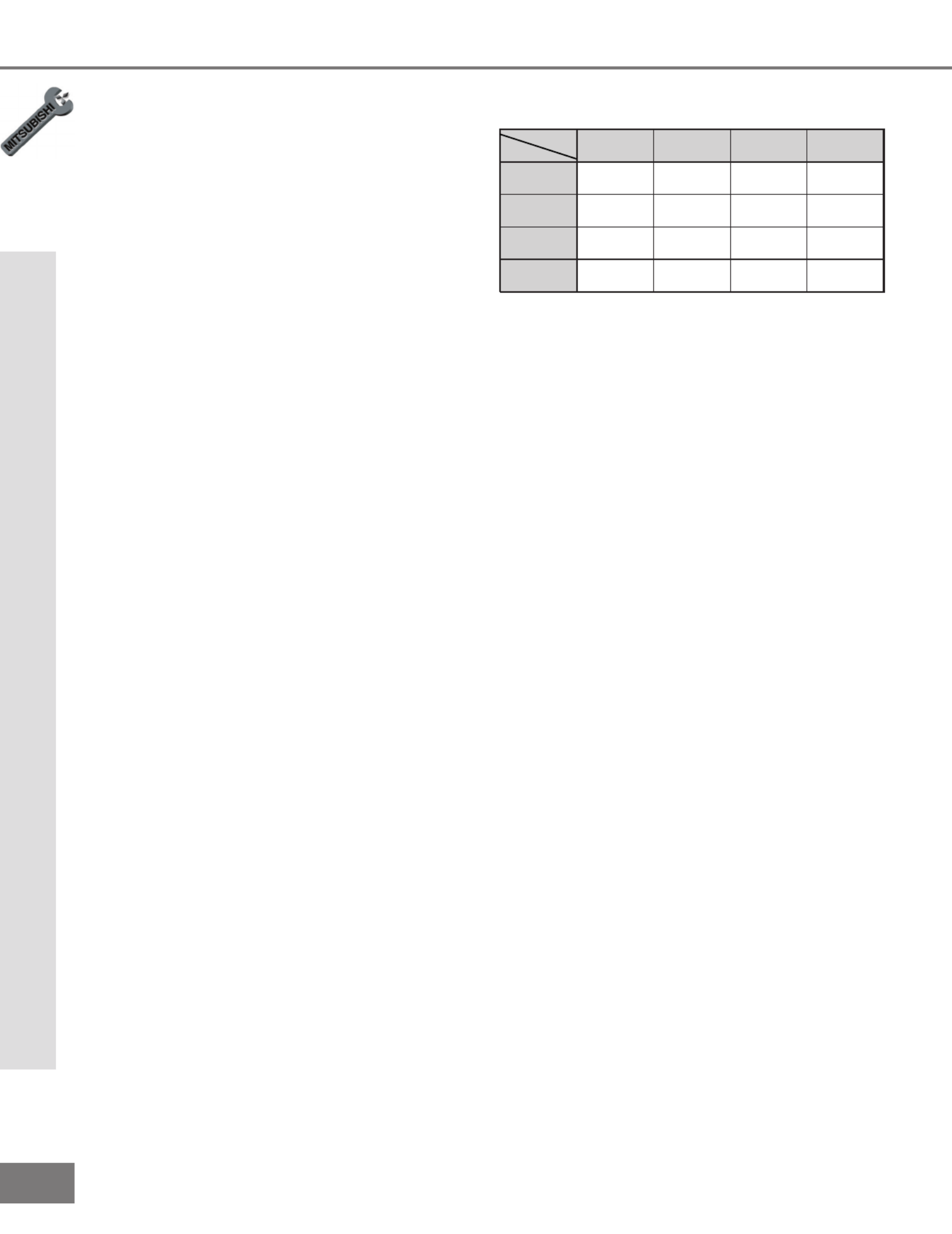
How Connections Affect the PIP
How Connections Affect the PIP
To see a picture in the PIP inset, you may
need to select an input source. If the only
input connected is ANT-A, then both the
main picture and the PIP insert will be from
that input source. If other video equipment
is connected, you may be able to view these
input sources as the PIP insert. When
connecting your new Mitsubishi bigscreen,
it is important to understand which main
picture and PIP input sources can and
cannot be used together. Table 1 shows
which inputs can and cannot be used
together and their limitations. To see which
input is being displayed as the main picture,
press INFO on the TV remote control. To
see which input is being displayed as the
PIP and for PIP operating instructions, see
Operation of PIP, pages 50-51.
How Connections Affect the System 4 Home Theater IR Control
Models VS-60719 and VS-70709
The Mitsubishi System 4 Home Theater IR
Control is a special feature that makes it
easier to use your TV with a digital surround
sound A/V receiver. Once your equipment
is properly connected and set up, your TV
and digital A/V receiver will change inputs
together, to match your selected video input
with the corresponding audio input.
When you change inputs on your TV to
watch different video products, your TV will
send signals via your remote control and the
infrared emitters to your digital A/V receiver
to change inputs. You will automatically
hear the high quality digital surround sound
from digital products like your DVD player,
and high quality analog stereo or surround
sound from non-digital products like your
VCR.
Additionally, all IR remote signals from your
Mitsubishi remote or other manufacturers
remote will be passed through your TV to
your A/V devices. Your A/V devices can
be hidden or behind cabinet doors and con-
trolled by pointing the remote at the TV.
Table 1. How connections affect the PIP.
*PIP must be the same channel as MAIN.
PIP
NIAM A-TNA B-TNA 3-1STUPNI TNENOPMOC
TUPNI
A-TNA
KO PIPON KO
B-TNA
KO *KO KO
3-1STUPNI
KO KO KO
TNENOPMOC
TUPNI
KO KO KO
NO COMPONENT
PIP
NO COMPONENT
PIP
NO COMPONENT
PIP
NO COMPONENT
PIP
15
15
Part II: Installation
How Connections Affect the System 4 Home Theater IR Control
Special Setups: A/V Equipment
VCR: Connect the cables to the TV as
directed on page 17, with the following
exception: Connect the audio output con-
nection to the appropriate input on the back
of the A/V receiver (as shown in table 1).
DVD: Connect the cables as directed on
page 19 (using the COMPONENT input),
with the following exception: Connect the
digital audio output connection on the DVD
player to the appropriate digital input on the
back of the digital A/V receiver (as shown
in table 1).
A/V Receiver: Connect as directed on
page 18, then complete the following two
steps. Use an S-Video cable in step 1 if
you have an S-Video VCR. The TV outputs
should be connected to the A/V receivers
input marked TV.
•Auto Standby: ON (See your A/V receiver’s
Owner’s Guide for this procedure). For all TV
use, the sound will come from the A/V receiver.
Not available with all A/V receivers.
•Digital Input Assignment for DVD: Assign the
digital input you used for your DVD player to the
A/V receiver’s DVD input selector. This proce-
dure is explained in your A/V receiver’s Owner’s
Guide.
Infrared Emitter: Connect as shown on
page 20.
Special Setups: TV
Menu selection for A/V connections, page 41.
•TV Speakers: OFF
•Audio Output: Fixed
Remote Control, pages 24-25.
•Set the slide switch to the TV position and follow
the programming instructions using the A/V
receiver code appropriate for your A/V receiver,
page 25 (gure 5).
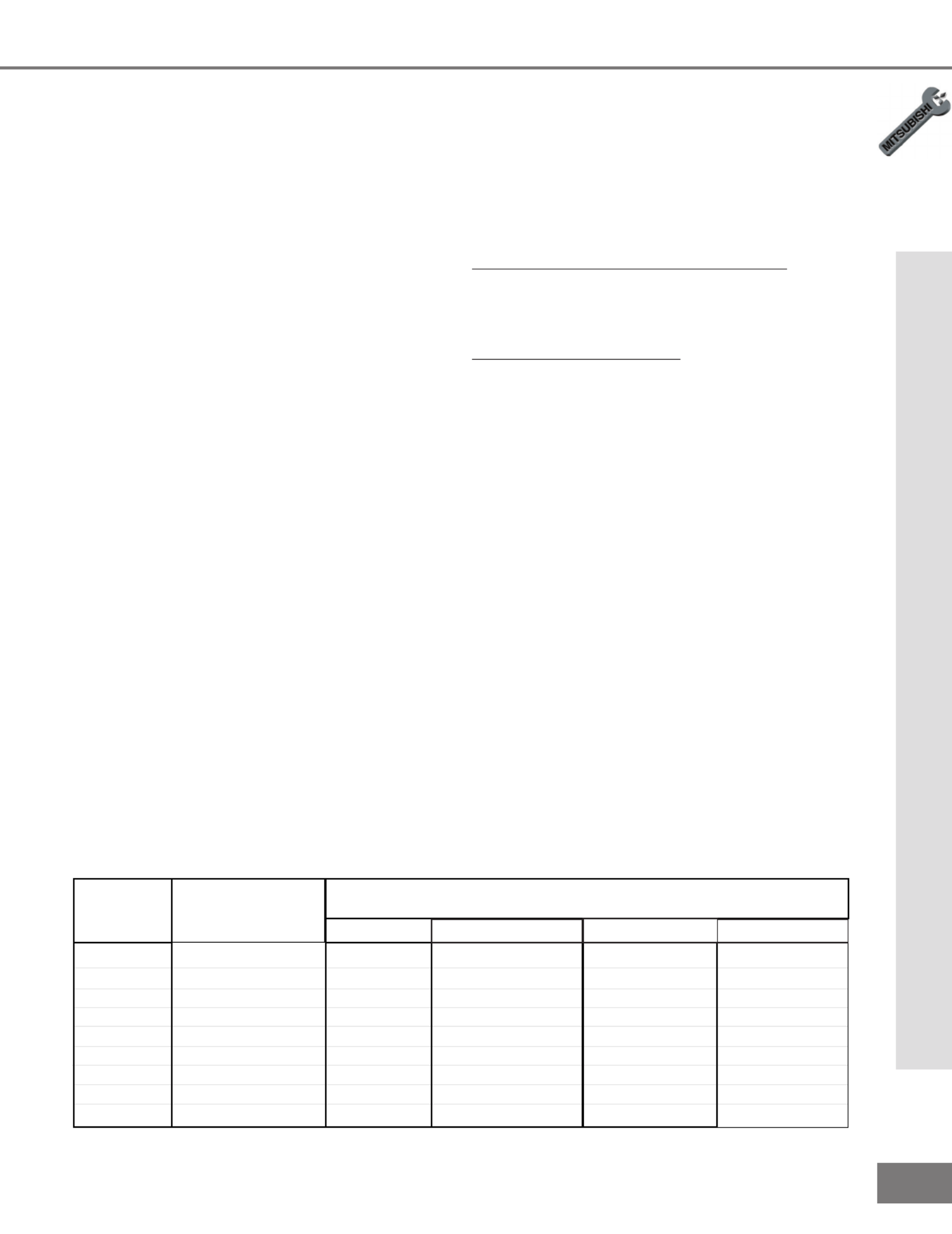
(For System 4 Home Theater IR Control)
Brand Model
The products listed at the top of this column should connect to the inputs
on the back of the appropriate A/V receiver listed to the left.
VCR
SAT/DBS/DTV
TV / Cable DVD
Mitsubishi
Mitsubsihi
Denon
JVC
Kenwood
Onkyo
Pioneer
Sony
Yamaha
M-VR800 / M-VR1000
M-VR700 / M-VR900
RX-888V
VR-2080
TX-DS575
VSX-21
STR-DE825
RX-V2095
TV
TV
TV/DBS
TV
AV AUX
VIDEO 3
TV/SAT
TV/DBS
TV/DBS
VCR2
CABLE/DBS
VCR2
VIDEO 2
LD
VIDEO 2
VIDEO 2
VIDEO 2
VCR 2
VCR1
VCR
VCR1
VCR 1
VIDEO 1
VIDEO 1
VCR 1
VIDEO 1
VCR1
DVD
DVD
DVD/LD
DVD
DVD
DVD
DVD/LD
DVD/LD
DVD/LD
Table 1. A/V receiver back panel input table

16
16
Additional connection cables are not
provided with the TV. They should be
available at most electronic stores.
Part II: Installation
Connecting an Antenna, Wall Outlet Cable, or Cable Box
Connecting an Antenna, Wall Outlet Cable, or Cable Box
Separate UHF and VHF Antennas
(Figure 1)
1
Connect the UHF and VHF antenna
leads to the UHF/VHF combiner.
2
Push the combiner onto ANT-A on the
TV back panel.
UHF/VHF combiners are not provided
with the TV. They should be available at
most electronic stores.
Twin Lead Antenna, Coaxial Lead
Antenna, or Wall Outlet Cable
For antenna with twin at leads (Figure 2)
1
Connect the 300ohm twin leads to the
transformer.
2
Push the 75ohm side of the transformer
onto ANT-A on the TV back panel.
300ohm to 75ohm matching transform-
ers are not provided with the TV. They
should be available at most electronic
stores.
For cable or antenna with coaxial lead (Figure 2)
3
Connect the incoming cable to ANT-A on
the TV back panel.
Cable Box
(Figure 3)
1
Connect the incoming cable to ANT-A on
the TV back panel.
Connect two coaxial cables as follows:
2
One from LOOP-OUT on the TV back panel to
IN on the cable box back panel.
3
One from OUT on the cable box back panel to
ANT-B on the TV back panel.
ANT-A
IR EMITTER HOME THEATER
S-VIDEO
COMPONENT
L
(MONO)
R
ANT -B
CABLE
LOOP-OUT
INPUT INPUT OUTPUT
FIXED/
VARIABLE
2 1
VHF/UHF
(75 OHMS)
V
I
D
E
O
A
U
D
I
O
TUNER/
MONITOR
L
R
Y
Cb
DVD
(YCrCb)
AUDIO
Cr
External
Antenna
or Cable
Back Side
Flat Twin Lead
UHF Antenna
(Channels 14-69)
VHF Antenna
(Channels 2-13)
300 Ohm to
75 Ohm
Combiner
Flat Twin Lead
TV back panel
UHF
VHF
2
1
Figure 1. Connecting separate UHF and VHF antennas.
ANT-A
IR EMITTER HOME THEATER
S-VIDEO
COMPONENT
L
(MONO)
R
ANT -B
CABLE
LOOP-OUT
INPUT INPUT OUTPUT
FIXED/
VARIABLE
21
VHF/UHF
(75 OHMS)
V
I
D
E
O
A
U
D
I
O
TUNER/
MONITOR
L
R
Y
Cb
DVD
(YCrCb)
AUDIO
Cr
300 Ohm Flat
Twin Lead
Optional 300 Ohm to 75 Ohm
Matching Transformer
75 Ohm
Coaxial Cable
TV back panel
1
2
3
Figure 2. Connecting twin lead antenna, coaxial lead
antenna, or wall outlet cable.
ANT-A
S-VIDEO
L
(MONO)
R
ANT -B
CABLE
LOOP-OUT
INPUT INPUT OUTPUT
FIXED/
VARIABLE
2 1
VHF/UHF
(75 OHMS)
V
I
D
E
O
A
U
D
I
O
TUNER/
MONITOR
L
R
Y
Cb
DVD
(YCrCb)
AUDIO
Cr
COMPONENT
IR EMITTER HOME THEATER
OUT
Cable Box
back panel section
TV back panel
IN
Incoming
Cable
1
2
3
Figure 3. Connecting the cable box.
17
17
Additional connection cables are not
provided with the TV. They should be
available at most electronic stores.
Part II: Installation
Connecting a VCR
Antennas or Wall Outlet Cable
(Figure 1)
1
Connect the incoming cable to ANT-A on
the TV back panel.
Connect two coaxial cables as follows:
2
One from LOOP-OUT on the TV back panel to
ANTENNA IN on the VCR back panel.
3
One from VCR back panel ANTENNA OUT to
ANT-B on the TV back panel.
4
Now complete gure 3, steps 1-2.
Connecting a VCR
Cable Box
(Figure 2)
1
Connect the incoming cable to ANT-A on
the TV back panel.
Connect three coaxial cables as follows:
2
One from LOOP-OUT on the TV back panel to
IN on the back of the cable box.
3
One from OUT on the back of the cable box to
ANTENNA IN on the VCR back panel.
4
One from ANTENNA OUT on the VCR back
panel to ANT-B on the TV back panel.
5
Now complete gure 3, steps 1-2.
Composite Video with Audio or
S-Video with Audio
(Figure 3)
1
Connect a video cable from VIDEO
OUT on the VCR back panel to VIDEO
INPUT-1, or INPUT-2 on the TV back
panel, or INPUT-3 on the TV Front Con-
trol Panel.
If you have an S-VHS VCR, follow the same
steps using the S-Video terminals on the VCR
and TV (in place of the composite terminals).
2
Connect a set of audio cables from
AUDIO OUT on the VCR back panel to
AUDIO INPUT-1, or INPUT-2 on the TV
back panel, or INPUT-3 on the TV Front
Control Panel. The red cable connects
to the R (right) channel and the white
cable connects to the L (left) channel. If
your VCR is mono (non-stereo), connect
only the white (left) cable.
ANT-A
S-VIDEO
L
(MONO)
R
ANT -B
CABLE
LOOP-OUT
INPUT INPUT OUTPUT
FIXED/
VARIABLE
2 1
VHF/UHF
(75 OHMS)
V
I
D
E
O
A
U
D
I
O
TUNER/
MONITOR
L
R
Y
Cb
DVD
(YCrCb)
AUDIO
Cr
IR EMITTER HOME THEATER
COMPONENT
IN
OUT
Antenna
AUDIO OUT AUDIO IN VIDEO OUT
(Y/C)
MONITOR
1
L
R
L
R
12
VCR back panel
If your VCR has a video
channel or RF ON/OFF
switch, set to OFF.
Attach
only
one
cable
type
1
1
Attach
only
one
cable
type
1
1
2
2
TV back panel
White
Red
White
Red
Figure 3. Connecting the VCR Audio/Video.
AUDIO OUT AUDIO IN VIDEO OUT
(Y/C)
MONITOR
1
L
R
L
R
12
IN
OUT
Antenna
VCR back panel
ANT-A
S-VIDEO
L
(MONO)
R
ANT -B
CABLE
LOOP-OUT
INPUT INPUT OUTPUT
FIXED/
VARIABLE
2 1
VHF/UHF
(75 OHMS)
V
I
D
E
O
A
U
D
I
O
TUNER/
MONITOR
L
R
Y
Cb
DVD
(YCrCb)
AUDIO
Cr
COMPONENT
IR EMITTER HOME THEATER
TV back panel
Incoming Cable
Cable Box
Rear Terminals
INOUT
1
2 4
2
3
3
4
Figure 2. Connecting VCR with cable box.
AUDIO OUT AUDIO IN VIDEO OUT
(Y/C)
MONITOR
1
L
R
L
R
1 2
ANT-A
S-VIDEO
L
(MONO)
R
ANT -B
CABLE
LOOP-OUT
INPUT INPUT OUTPUT
FIXED/
VARIABLE
2 1
VHF/UHF
(75 OHMS)
V
I
D
E
O
A
U
D
I
O
TUNER/
MONITOR
L
R
Y
Cb
DVD
(YCrCb)
AUDIO
Cr
COMPONENT
IR EMITTER HOME THEATER
TV back panel
Incoming Cable
IN
OUT
Antenna
VCR back panel
1
2 3
3
2
Figure 1. Connecting VCR with antennas or wall outlet
cable.

18
18
ANT-A
S-VIDEO
L
(MONO)
R
ANT -B
CABLE
LOOP-OUT
INPUT INPUT OUTPUT
FIXED/
VARIABLE
2 1
VHF/UHF
(75 OHMS)
V
I
D
E
O
A
U
D
I
O
TUNER/
MONITOR
L
R
Y
Cb
DVD
(YCrCb)
AUDIO
Cr
COMPONENT
IR EMITTER HOME THEATER
AV Receiver (M-VR900)
Back panel section
Attach
only
one
cable
type
1
123
W
h
i
t
e
White
R
e
d
Red
TV back panel
ANT-A
IR EMITTER HOME THEATER
S-VIDEO
COMPONENT
L
(MONO)
R
ANT -B
CABLE
LOOP-OUT
INPUT INPUT OUTPUT
FIXED/
VARIABLE
21
VHF/UHF
(75 OHMS)
V
I
D
E
O
A
U
D
I
O
TUNER/
MONITOR
L
R
Y
Cb
DVD
(YCrCb)
AUDIO
Cr
Red
Audio system back panel section
OUTOUT
OUT
ININININ
SUBWOOFER
(MONO)
CD AUX TAPE
1
TAPE
2
L
R
TV back panel
White
White
1
Red
Please see your A/V receiver Owner’s
Guide for more detailed connections.
Additional connection cables are not
provided with the TV. They should be
available at most electronic stores.
Part II: Installation
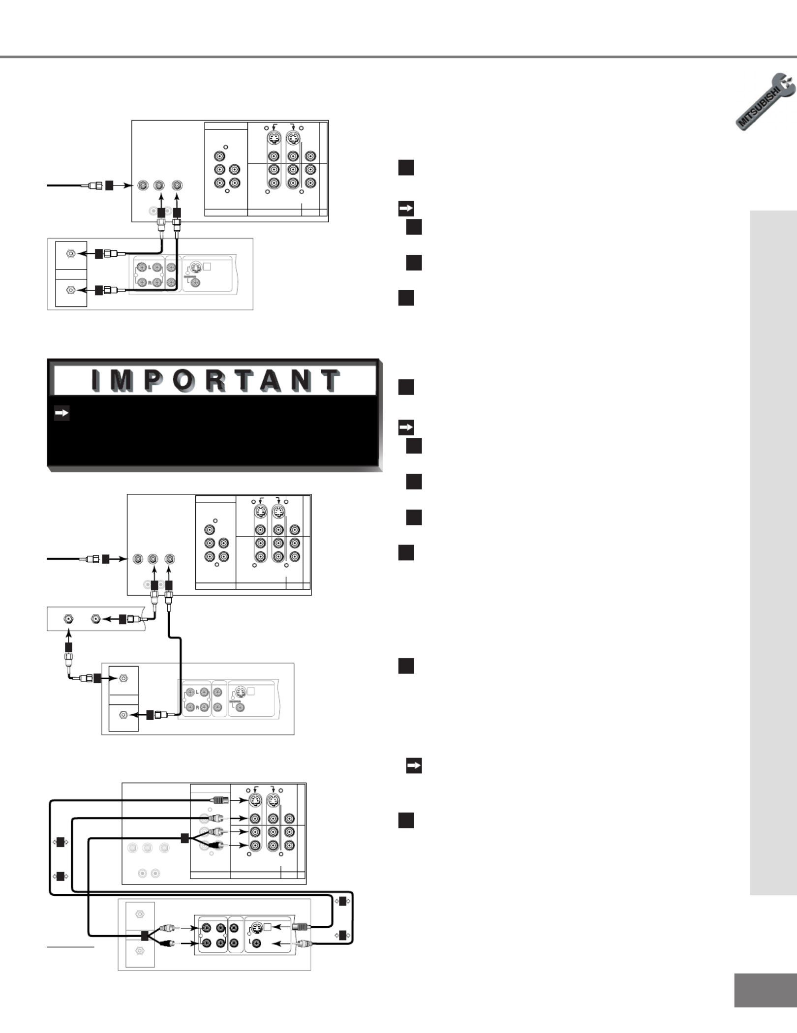
Connecting an Audio Receiver
Connecting an Audio Receiver
Stereo Audio System
(Figure 1)
1
Connect the audio cables from AUDIO
MONITOR OUTPUT on the TV back
panel to TV IN or AUX IN terminals on
the back of the audio system. The red
cable connects to the R (right) channel,
and the white cable connects to the L
(left) channel.
2
Turn off the TV’s speakers through the
Audio/Video Settings Menu, page 41.
3
Set the audio system’s input to the TV
or AUX position to hear the TV’s audio
through your stereo system.
A/V Receiver
(Figure 2)
1
Connect a video cable or S-Video
cable from VIDEO MONITOR OUT on
the back of the A/V receiver to VIDEO
INPUT-1 on the TV back panel.
2
Connect a video cable from VIDEO
MONITOR OUTPUT on the TV back
panel to VIDEO TV IN on the back of
the A/V receiver.
3
Connect a set of audio cables from
AUDIO MONITOR OUTPUT on the TV
back panel to AUDIO TV IN on the
back of the A/V receiver. The red cable
connects to the R (right) channel, and
the white cable connects to the L (left)
channel.
Figure 1. Connecting the Stereo Audio System
Figure 2. Connecting the A/V Receiver.

19
19
Part II: Installation
Do not display the same stationary images on the screen for more that 15%
of your total TV viewing in one week. Examples of stationary images are
letterbox top/bottom bars from DVD or other video sources, side bars when showing standard
TV pictures on widescreen TV’s, stock market reports, video game patterns, station logos, web
sites, or stationary computer images. Such patterns can unevenly age the picture tubes causing
permanent damage to the TV. Please see pages 21 and 52 for a detailed explanation.
WARNING:
Connecting a DVD Player
DVD Player with Component Video
(Figure 1)
Connect the Component Video cables
from Y/Cr/Cb or Y/Pr/Pb VIDEO OUT
on the back of the DVD player to
COMPONENT on the TV back panel,
matching the correct components:
1
Y to Y
2
Cr or Pr to Pr
3
Cb or Pb to Pb
Connect a set of audio cables from
AUDIO OUT on the back of the DVD
player to COMPONENT AUDIO Input on
the TV back panel. The red cable
4
connects to the R (right) channel, and
the white cable
5
connects to the L
(left) channel.
See Appendix B, page 57, for component
video signal compatibility information.
For digital audio connections, see your
DVD and A/V receiver Owner’s Guides.
Connecting a DVD Player or S-Video Device
ANT-A
S-VIDEO
L
(MONO)
R
ANT -B
CABLE
LOOP-OUT
INPUT INPUT OUTPUT
FIXED/
VARIABLE
21
VHF/UHF
(75 OHMS)
V
I
D
E
O
A
U
D
I
O
TUNER/
MONITOR
L
R
Y
Cb
DVD
(YCrCb)
AUDIO
Cr
IR EMITTER HOME THEATER
COMPONENT
AUDIO OUT AUDIO IN VIDEO OUT
(Y/C)
L
R
L
R
12
2
1
1
2
TV back panel
Any S-Video Device
White
Red
Figure 2. Connecting an S-Video Device.
S-Video Device
(Figure 2)
1
Connect an S-Video cable from
S-VIDEO OUT on the device back panel
to S-VIDEO INPUT-1, or INPUT-2 on the
TV back panel, or INPUT-3 on the TV
Front Control Panel.
2
Connect a set of audio cables from
AUDIO OUT on the device back panel
to AUDIO INPUT-1 or INPUT-2 on the
TV back panel. The red cable connects
to the R (right) channel and the white
cable connects to the L (left) channel.
If your device is mono (non-stereo), con-
nect only the white (left) cable.
Connecting an S-Video Device
Figure 1. Connecting the DVD player.
ANT-A
S-VIDEO
L
(MONO)
R
ANT -B
CABLE
LOOP-OUT
INPUT INPUT OUTPUT
FIXED/
VARIABLE
21
VHF/UHF
(75 OHMS)
V
I
D
E
O
A
U
D
I
O
TUNER/
MONITOR
L
R
Y
Cb
DVD
(YCrCb)
AUDIO
Cr
COMPONENT
IR EMITTER HOME THEATER
VIDEO
S
Y
CB
CR
VIDEO OUT
BITSTREAM/PCM5.1 CH SURROUND 2CH
L
R
CENTER
SUBWOOFER SURROUND FRONT COAXIAL OPTICAL
AUDIO OUT
AC IN
MITSUBISHI
DVD PLAYER
MODEL DD-5000
POWER SUPPLY 120V~ 60Hz
POWER CONSUMPTION 20W
MITSUBISHI DIGITAL ELECTRONICS
DI STRI BUTED BY
9351 JERONIMO ROAD
IRVINE, CA 92618
MADE IN JAP AN
AMERICA, I NC.
SERIAL NO .
MANUFACTURED
White
Red
DVD back panel
2
1
1
3
5
5
4
4
2
3
TV back panel

20
20
ANT-A
IR EMITTER HOME THEATER
S-VIDEO
COMPONENT
L
(MONO)
R
ANT -B
CABLE
LOOP-OUT
INPUT INPUT OUTPUT
FIXED/
VARIABLE
21
VHF/UHF
(75 OHMS)
V
I
D
E
O
A
U
D
I
O
TUNER/
MONITOR
L
R
Y
Cb
DVD
(YCrCb)
AUDIO
Cr
TV back panel
A/V Receiver
1
D I G I T A L
SU R R O U N D
SCH
Other A/V Device
D I G I T A L
SU R R O U N D
SCH
Figure 1. Connecting the System 4 Home Theater IR
Control.
See page 53 for details on using the
TV’s IR emitter to control a Mitsubishi
A/V receiver.
Part II: Installation
Connecting the System 4 Home Theater IR Control
1
Connect the IR emitter to IR EMITTER
HOME THEATER on the TV back panel.
2
Place the IR emitter cable under or
along the side of the A/V device. Place
the IR lens directly in front of the A/V
device’s infrared signal receiver. Infra-
red signal receivers are usually behind
the front translucent panel of the device.
3
Place unused transmitters in an out-of-
the-way location.
4
For permanent installation of the IR
emitter cable, use the included adhesive
tape to secure the bottom of the emitter
to the anchoring object of your choice.
Connecting the System 4 Home Theater IR Control
Models VS-60719, VS-70709. (Figure 1)

21
21
Part II: Installation
IMPORTANT NOTES
Warning: Do not leave stationary or letterbox images on-screen for
extended periods of time. Mix the types of pictures shown.
Uneven picture tube aging is NOT covered by your warranty.
The normal use of a TV should include
a mixture of TV picture types. The most
frequently used picture types should ll
the screen with constantly moving images
rather than stationary images or patterns.
Displaying the same stationary patterns
over extended periods of time, or display-
ing the same stationary pattern frequently
can leave a subtle but permanent ghost
image. To avoid this, mix your viewing
pattern. Do not show the same stationary
image for more than 15% of your total TV
viewing in any one week. Display con-
stantly moving and changing images that
ll the screen whenever possible.
This projection TV uses picture tubes to
project the image onto the screen. All
picture tubes age with use. As they
age, their light output is gradually reduced.
Normal TV pictures ll the screen with
constantly changing images. Under these
conditions, picture tubes age at an even
rate across the entire screen. This main-
tains a TV picture that is evenly bright over
the whole screen. Stationary images or
images that only partially ll the screen
(leaving black or colored bars to ll the
screen), when used over extended periods
of time or when viewed repeatedly, can
cause uneven aging of the phosphors
and leave subtle ghosts of the stationary
images in the picture
Still or stationary images may be received
from broadcasters, cable channels, sat-
ellite channels, DVD discs, video tapes,
laser discs, on-line services, web/internet
searching devices, video games, and digi-
tal TV tuner/converter boxes. Examples of
these types of images can be, but are not
limited to the following:
Letterbox top/bottom black bars:
shown at the top and bottom of the TV
screen when you watch a widescreen
(16:9) movie on a standard (4:3) TV.
: solid bars shown on Side bar images
each side of an image when watching
a standard (4:3) program on a wide-
screen (16:9) TV.
Stock-market report bars: ticker run-
ning at the bottom of the TV screen.
Shopping channel logos & pricing dis-
plays: bright graphics that are shown con-
stantly or repeatedly in the same location.
Video game patterns and scoreboards
Bright station logos: moving or low-
contrast graphics are less likely to cause
uneven aging of the picture tubes.
: or any On-line (internet) web sites
other stationary or repetitive computer style
images.

If you have questions regarding your television, call
Consumer Relations
at (800) 332-2119, or email us at
MDE Aser v ice@bi gsc reen. mea. com
To order replacement or additional remote controls or owner’s
guides
call (800) 553-7278
or
visit our website at w ww.mit sub ishi -tv.c om

23
23
Setup
Programming the Remote Control:
To Control Other A/V Products .... 24-25
To Activate the System 4 IR Home
Therater IR Control .................... 26-27
on-screen menu system.....28
Menu Screens (Overview)... 29-30
Setup ........................................31
Memorize Channels ..............31
Clock ......................................31
Language...............................31
Closed Captions......................32
V-Chip Parent Lock........... 33-35
Channel Edit ............................36
Advanced Features .................37
Timer ......................................37
Convergence .........................38
Advanced Convergence .......39
Special Features ...................39
Audio/Video Settings........ 40-41
A/V Setting Descriptions ........ 42-43
VS-60719 & VS-70709

24
24
TV AUDIO
CABLE/DBS DVD
VCR
1
Code to enter:
To reset to default code, enter 000
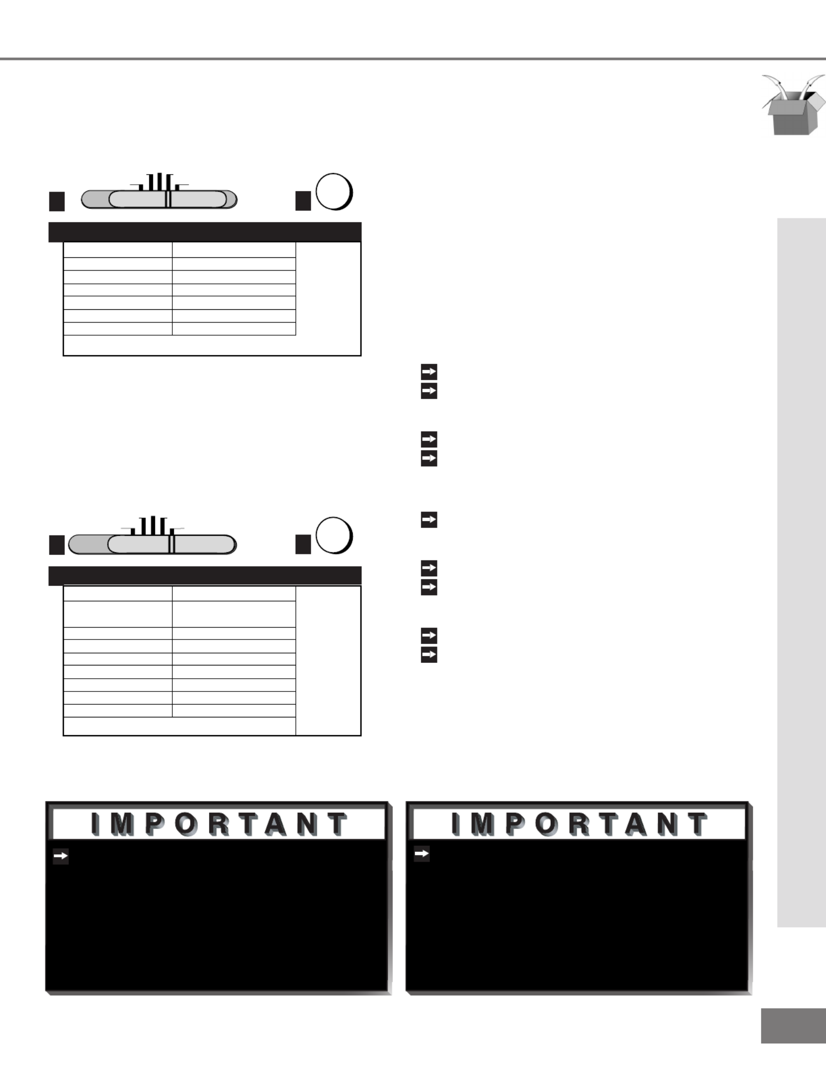
Cable box brand
General Instruments
Jerrold
Oak
Pioneer
Scientific Atlanta
Zenith
111, 119, 120, 121, 122,
123, 124, 125, 126, 127
102, 137, 139
101, 116
111, 112, 113
100, 117
If your
cable box
code is not
listed here,
please see
page 62
for a
complete
listing.
Cable Box Codes
3
2
POWER
Figure 1. Programming the remote to control your cable
box.
Figure 3. Programming the remote to control your VCR.
TV AUDIO
CABLE/DBS DVD
VCR
1 2
POWER
Code to enter:
To reset to default code, enter 000
VCR brand
Mitsubishi
Hitachi
JVC
Phillips / Magnivox
Panasonic
RCA
Sony
Toshiba
001, 002
020, 043, 065
030, 054, 059
043, 044, 051
041, 042, 043
020, 053, 065
048, 049, 050
021, 066
If your
VCR
code is not
listed here,
please see
page 62
for a
complete
listing.
VCR Codes
3
TV AUDIO
CABLE/DBS DVD
VCR
1 2
POWER
Code to enter:
To reset to default code, enter 000
Satellite brand
Mitsubishi - DBS
Dishnetwork
Hughes - DSS
RCA - DSS
Sony - DSS
Toshiba - DSS
Panasonic - DSS
Primestar
173
175
173
176
177
170
174
178
If your
satellite
receiver
code is not
listed here,
please see
page 62
for a
complete
listing.
Satellite Receiver Codes
3
Figure 2. Programming the remote to control your satel-
lite receiver.
If you cannot turn the cable box ON
by pressing POWER, try pressing CHAN-
NEL or the number buttons.
When set to TV, the PLAY, STOP, REW/
REV, and FF/FWD buttons will operate
the VCR after the VCR codes have been
properly programmed into the remote
control.
Part III: Setup
Programming the Remote Control: To Control Other A/V Products
Programming the Remote Control: To Control Other A/V Products
To Program the Remote to Control
Other Brands of Audio and Video
Products:
(Figures 1-5)
1
Move the slide switch at the top of
the remote to the product you want to
control.
2
Press and hold the POWER button on
the remote control.
3
Enter the rst three digit code listed for
your equipment, and then release the
POWER button on the remote control.
4
Point the remote control at the equip-
ment and press the POWER button.
If the equipment responds, the remote
control is properly programmed to oper-
ate the equipment. If the equipment
does not respond, repeat steps 2-4 with
the next three digit code listed in step 3
for your equipment.
25
25
TV AUDIO
CABLE/DBS DVD
VCR
12
POWER
Code to enter:
To reset to default code, enter 000
DVD/LDP brand
Mitsubishi (DVD)
Mitsubishi (LDP)
Panasonic
Pioneer DVD (LDP)
Sony
Toshiba
003
016, 017
250
252 (016, 017)
254
253
If your
DVD
code is not
listed here,
please see
page 62
for a
complete
listing.
DVD/LDP Player Codes
3
Figure 4. Programming the remote to control your DVD/
LDP.
TV AUDIO
CABLE/DBS DVD
VCR
1 2
POWER
Code to enter:
To reset to default code, enter 000
Audio brand
Mitsubishi A/V receiver
and/or CD player
Denon
Kenwood
JVC
Onkyo
Pioneer
Sony
Yamaha
Set M-VR1000 or M-VR800 to 015
Set M-VR900 or M-VR700 to 010
234, 235, 236
200, 208
232, 233
209, 214
205, 207
222
201, 208
If your
audio
code is not
listed here,
please see
page 62
for a
complete
listing.
A/V Receiver Codes
3
Figure 5. Programming the remote to control your A/V
receiver.
If the slide switch is set to TV when you
enter an A/V receiver code, VOLUME
and MUTE will control the A/V receiver
rather than the TV. To return volume
and mute control to the TV, set the slide
switch to TV, press and hold POWER
and enter 000.
Some manufacturers may change their
products, or they may use more than
one remote control system. If this is the
case, your remote control may not be
able to operate your VCR, DVD, cable
box, satellite receiver, or A/V receiver.
Part III: Setup
Programming the Remote Control: To Control Other A/V Products
After entering the correct codes for each
position of the remote control, use the slide
switch to select the product to control when
an operational button is pressed. If you
enter a code from the AUDIO chart while
the slide switch is set to TV, the volume
and mute functions change to match the A/V
receiver. This is useful when using an A/V
receiver with the TV all the time. In all
other cases, only one of the below devices
is allowed for each slide switch position.
TV position:
TV
A/V receiver (volume and mute only)
Cable/DBS position:
Cable box
Satellite receiver
VCR position:
VCR
DVD position:
DVD
LD Player
Audio position:
A/V receiver
Mitsubishi CD player [If you have a Mitsubishi A/V
receiver, the audio position may be used in conjunction with
select Mitsubishi CD players. Your audio position must be
programmed to either 010 or 011. Plug the CD player power
cord into a switched outlet on the back of your A/V receiver.
Pressing the POWER button will then turn on your A/V receiver,
in turn, turning on your CD player. On select CD players, the
transport controls (FF, Play, Rew, etc.) in the audio position will
operate the CD player.]
Programming the Remote Control: To Control Other A/V Products

26
26
Part III: Setup
Activation of the System 4 Home
Theater IR Control
You can, with certian digital A/V receivers,
set up the remote control to automatically
select the correct audio input when you
press the HOME THEATER button. At the
same time, the TV will select the correct
video input. This allows you to watch your
best type of video (Component, S-Video)
with your best type of audio (Dolby Digital,
Pro Logic, etc.) conveniently. See System
4 Home Theater IR Control, page 20, for
connection instructions.
Once properly activated, when the HOME
THEATER button is pressed, System 4 Oper-
ates in 2 parts:
AUDIO
Changes a compatible digital A/V
receiver to the correct input for the device
you wish to operate.
VIDEO
Changes the TV to the correct input
for the device you wish to operate.
Both functions can operate simultaneously
with one touch of the HOME THEATER
button. However, you may activate only one
if you desire (video to control the TV or
audio to control the A/V Receiver). The
remote control must be programmed to the
appropriate A/V Receiver code prior to the
activation of the audio portion (see To Pro-
gram the Remote to Control Other Brands of
Audio and Video Products, page 24).
Programming the Remote Control:
To Activate the System 4 Home Theater IR Control
Models VS-60719 and VS-70709
Activate the System 4 Home Theater IR Control
To Activate the Audio Portion:
1
Press and hold the HOME THEATER button.
2
Press and release the AUDIO button.
To Activate the Video Portion:
(Figure 1)
1
Press and hold the HOME THEATER button.
2
Press and release the VIDEO button.
3
Name the TV input as instructed.
Name Input
Cannot be named
CABLE
DBS
VCR
DVD
Device You Are Using
Cable Box connected to ANT-A or ANT-B
Cable Box connected to Inputs 1-3
Satellite Receiver connected to any input
VCR connected to Inputs 1-3
DVD connected to Inputs 1-3
Name TV Input as Shown Below
(see pg 36 for naming help)
3
2VIDEO
1
HOME
THEATER
Figure 1. Activating the video portion of System 4.

29
29
Part III: Setup
Menu Screens (Overview)
SETUP Menu
(Figure 1)
You can put channels in memory, enter
the CLOCK submenu, and select the menu
system to display in English or Spanish
(Español).
CAPTIONS Menu
(Figure 2)
Display captions or text, and choose black or
gray as the background color for the closed
caption area.
Menu Screens (Overview)
V-CHIP PARENT LOCK Menu
(Figure 3)
Block or allow programming based upon
rating signals sent by the broadcast station,
or by time.
Figure 1. Setup menu.
Figure 2. Captions menu.
Figure 3. V-Chip Parent Lock menu.

30
30
Part III: Setup
Menu Screens (Overview)
ADVANCED FEATURES Menu
(Figure 2)
Set your TV to turn on automatically, con-
verge (align) the three main colors, display a
blue screen when viewing an input with no
signal, turn off the Front Panel Controls, and
view the PIP Demo Mode.
AUDIO/VIDEO SETTINGS
(Figure 3)
Adjust some or all of the A/V settings. Each
input can be set to your preferences. A/V
Memory Reset on the menu allows you to
return the A/V settings for the current input
to the factory presets. A/V Reset on the
front panel resets all inputs at once.
Menu Screens (Overview)
CHANNEL EDIT Menu
(Figure 1)
Use to customize the channel information for
Ant-A and Ant-B. Manually add or delete
channels from memory, name channels for
Ant-A and Ant-B, or add your favorite chan-
nels to the SQV (Super Quick View™)list.
Figure 1. Channel Edit menu.
Figure 3. Audio/Video menu.
Figure 2. Advanced Features menu.

31
31
Part III: Setup
Setup Menu: Memorize Channels, Clock, and Language
Memorize Channels
(Figure 1)
This selection memorizes the channels your
TV can receive and skips the unused or
weak channels. You can stop memorization
at any time by pressing CANCEL. Channels
memorized prior to pressing CANCEL will
stay in memory. After channels are memo-
rized, you may select memorized channels
in ascending or descending order by press-
ing the CHANNEL button on the remote con-
trol.
Memorize Channels, Clock, and Language
Clock Setup
(Figure 2)
Manually set the time for the TV, or select
Auto and the TV will automatically set the
time based upon Extended Data Service
(XDS) time data. This time data is usually
broadcast by your local PBS station.
Language
(Figure 3)
Display the on-screen menus in either
English or Spanish (Español). The rst
time your TV was powered on, you were
requested to select an on-screen menu lan-
guage. You may change your selection by
pressing the ENTER button on the remote
control.
Figure 3. Language menu.
Figure 2. Clock Setup menu.
Figure 1. Memorize Channels menu.

33
33
Part III: Setup
V-Chip Lock
V-Chip Parent Lock Menu: V-Chip Lock
If you forget your four-digit passcode,
see Appendix A, page 55.
V-Chip Lock
(Figure 1)
The V-Chip Lock allows you to Block or
Allow programs based upon rating signals
sent by the broadcasting station. The TV
comes from the factory with the V-Chip lock
in the Off setting. You can turn the lock
On within the V-Chip Menu. The factory
preset is TV-PG, allowing only programs
rated TV-PG or lower. You can change
the blocking level to various TV or movie rat-
ings, lettered categories, and by time. After
changing channels or inputs, there may be
up to a 5 second delay before the V-Chip
lock takes effect. The V-CHIP button on the
remote control enables you to conveniently
turn the lock on or off.
Entry to the V-Chip Lock
(Figures 2)
The rst time you select V-Chip Lock from
the MAIN menu, press the V-CHIP button
on the remote control, or after you have
canceled your passcode you will see the
screen shown in gure 2. Use the number
buttons on the remote control to input a four-
digit passcode, then press ENTER. You
can delete a character and move back one
space by pressing CANCEL. You can exit
without inputting a passcode by pressing
MENU or HOME. The next time you select
V-Chip Lock from the MAIN menu, or press
the V-CHIP button on the remote control,
you will see a menu screen similar to the
one in gure 3.
Figure 3. V-Chip Lock passcode screen (re-entry)
Figure 2. V-Chip Lock passcode screen (rst-time entry)
Figure 1. V-Chip Lock menu.

35
35
Part III: Setup
V-Chip Hours/Lock By Time
V-Chip Parent Lock Menu: V-Chip Hours/Lock By Time
V-Chip Hours/Lock By Time
(Figure 1)
V-CHIP HOURS/LOCK BY TIME will allow
you to activate the V-Chip or lock the entire
TV during specic hours.
V-Chip Start Time and V-Chip Stop
Time
(Figure 1)
Select the times you would like the V-Chip to
be Active. By setting the V-Chip Start Time
and V-Chip Stop Time to the same time, the
V-Chip will be active 24 hours a day.
Press or to slowly adjust the time.
Press and hold or to quickly adjust the
time.
Lock by Time, Lock Time, and
Unlock Time
(Figure 1)
Lock by Time locks the entire TV based
upon the Lock Time and Unlock Time. You
must input your 4-digit passcode to use the
TV when it is locked. By setting the Lock
Time and Unlock Time to the same time, the
Lock by Time will be active 24 hours a day.
Unlock Passcode Screen
(Figure 2)
To view a V-Chip blocked program or to
watch the TV during a scheduled lock time,
you must enter your 4-digit passcode. The
V-Chip block and Lock by Time will remain
disabled until the TV is powered off and then
on again.
Figure 1. V-Chip Hours/Lock By Time menu.
Figure 2. V-Chip Lock unlock passcode screen.

36
36
Part III: Setup
Input, Channel, Memory, Name and SQV™
Channel Edit Menu:Input, Channel, Memory, Name and SQV™
Channel
(Figure 1)
Select the channel you want to add or delete
from memory, name, or add to the SQV
Super Quick View™ list.
Memory
(Figure 1)
After all available channels have been mem-
orized with Memorize Channels, page 31,
weaker channels viewed with Ant-A or Ant-B
can be added and unwanted channels can
be deleted.
Use the CHANNEL button on the remote
control to view memorized channels.
Name
(Figure 1)
Channels shown on Ant-A or Ant-B can be
given names (up to four characters). After
you enter a name, it will appear on the TV
screen, next to the channel number. Inputs
1-3 can be renamed by scrolling through the
following list: Audio, AUX, Cable, CAM(camcorder),
DBS, DVD, Game, Laser, Surv (surveillance, or security),
S-VHS, VCR, VCR2, VHS, or Off.
SQV (Super Quick View™)
Using The Remote Control
Adding SQV channels using the remote con-
trol:
1
Use the CHANNEL or number buttons
to select the channel you want to add to
add to the list.
2
Press and hold the SQV button for
about 3 seconds. The letters “SQV” will
appear under the channel number, indi-
cating that the channel has been added
to the
Super Quick View™ memory.
Removing SQV channels using the remote
control:
1
Press the SQV button repeatedly to
select the channel to be removed from
the list.
2
While the channel number and SQV indi-
cator are still displayed on the screen,
press the CANCEL button. If the
CANCEL button is not pressed before
the SQV indicator disappears, the chan-
nel will not be removed.
3
When the SQV indicator disappears, the
channel has successfully been removed.
SQV (Super Quick View™)
Using The Menu Screen
(Figure 1)
SQV (Super Quick View™) allows you to put
together a list of your favorite channels from Ant-A
and Ant-B. You can quickly look through the list
using the SQV button. Once you have added a
channel to the SQV memory, “SQV” will appear
under the channel number any time the channel
number is displayed on the TV screen.
Input
(Figure 1)
Select Ant-A, Ant-B, or Inputs 1-3. For Ant-A
and Ant-B, you can add or delete channels
in memory, name channels, and add chan-
nels to the SQV (Super Quick View™) list.
For Inputs 1-3, you can rename the input.
Figure 1. Channel Edit menu.

37
37
The TV’s clock must be set before you
can set the timer. If you have not set
the clock and/or day, you will see the
CLOCK menu instead of the Timer menu.
Part III: Setup
Timer
Timer Menu
(Figure 2)
The timer can be turned On or Off. When
On, you need to select the time to turn on,
the day to turn on, and the channel to dis-
play. At your preselected time, the timer
will turn the TV on, and a message will be
displayed, “Press a key for the TV to stay
on”. Any button on the remote control must
be pressed within 5 minutes, or the TV will
turn itself off.
Set Time
Select the hour and minute, including AM or
PM, when the TV is to turn on.
Press or to slowly adjust the time.
Press and hold or to quickly adjust the
time.
Timer
(Figure 1)
The timer will automatically turn the TV on
(if it is off) at the time you schedule and
select.
Advanced Features Menu: Timer
Set Day
Select the days that the TV will turn on auto-
matically. You can select Everyday, Mon-Fri
(Monday through Friday), or the individual
days of the week.
Input
Select the input to use when the timer turns
on the TV. If the TV is already on, the timer
will turn the TV to this selected input.
Channel
When Ant-A or Ant-B is the selected input,
you may select any memorized channel.
The TV will tune to this channel when the
timer turns it on.
Figure 2. Timer menu.
Figure 1. Advanced Features menu.

38
38
Part III: Setup
Convergence
Advanced Features Menu: Convergence
Convergence Menu
(Figure 2)
Convergence aligns the entire screen at
once. Select either Red Convergence or
Blue Convergence to begin alignment. To
align 64 individual points, see Advanced
Convergence, page 39.
Convergence
(Figure 1)
Your Mitsubishi TV has three picture tubes
which are aligned to properly converge the
projected light beams on the screen. Each
picture tube projects a single color of red,
blue or green. During production, your
TV was carefully adjusted to properly align
these colors. As a special feature, you have
the ability to adjust the red and blue light
beams in reference to the xed green light
beam. This process is called convergence.
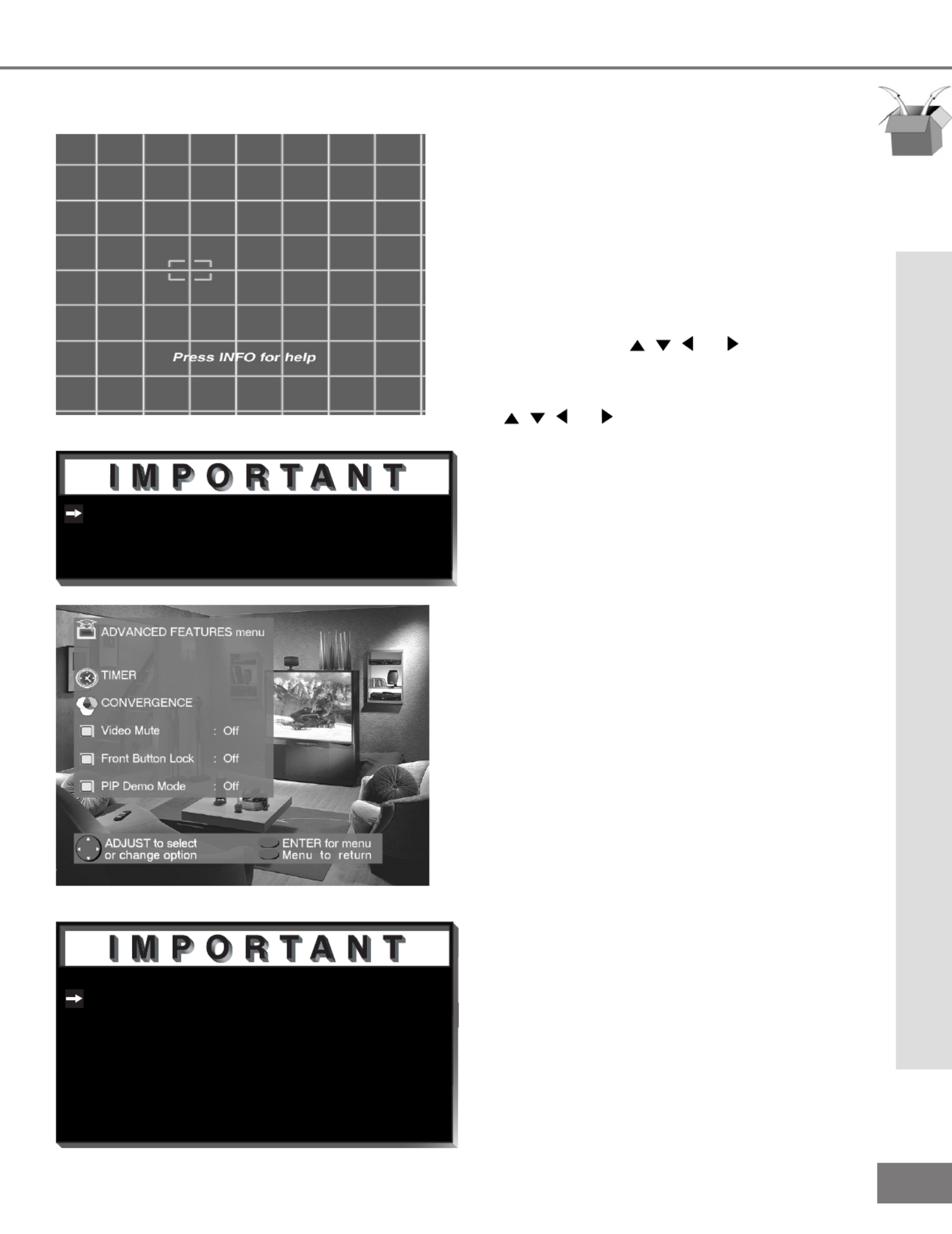
Convergence Screen
(Figure 3)
When the Red and Blue crosshairs are prop-
erly converged, the center-screen crosshairs
will appear white. You can use , , ,
or to move the Red and Blue crosshairs.
Press VIDEO to switch between Red and
Blue. Press AUDIO for the Advanced Con-
vergence screen, and see Advanced Conver-
gence, page 39, for instructions.
Reset Factory Defaults
(Figure 2)
This allows you to reset the convergence
to the factory settings. The message “Con-
vergence Reset Completed” will be dis-
played when the factory defaults have been
Figure 2. Convergence menu.
Figure 1. Advanced Features menu.
Figure 3. Convergence screen.
39
39
There are more than 64 line intersec-
tions, but the ashing bracket will only
stop at the 64 adjustment points.
The Front Button Lock can be disabled
from the Front Control Panel by depress-
ing the MENU button for 8 seconds.
When successful, the message “Front
Button Lock Disabled” will display on
the screen.
Part III: Setup
Advanced Convergence and Special Features
Advanced Features Menu: Advanced Convergence and
Special Features
Advanced Convergence
(Figure 1)
After adjusting the Red Convergence and
Blue Convergence, you can ne-tune your
TV by adjusting the Red and Blue conver-
gence at 64 individual points. Move the
ashing bracket to a position needing adjust-
ment by pressing , , , or . Press
ENTER to select the position (ashing will
stop). Move the Red or Blue line by press-
ing , , , or . Press VIDEO to switch
between the Red and Blue lines. A
position is properly converged when all
three lines combine to appear white. Press
ENTER to deselect the position (ashing will
resume), and move the brackets to the next
position needing adjustment. When com-
pleted, press MENU to save your changes,
and exit the Advanced Convergence screen.
PIP Demo Mode
(Figure 2)
PIP Demo Mode will demonstrate for you the
capabilities of your TV’s Picture-In-Picture
feature. When set to ON, the TV will cycle
through the available PIP formats, wait 2
minutes showing only the main picture, then
cycle again. You can stop the PIP demo at
any time by pressing the HOME button.
Video Mute
(Figure 2)
Video Mute lets you display a blue or
black background when no signal is being
received on inputs 1-4.
Front Button Lock
(Figure 2)
Front Button Lock lets you disable keys on
the front panel to prevent access to TV
functions from the front panel.
Figure 1. Advanced Convergence screen.
Figure 2. Advanced Features menu.

40
40
Part III: Setup
Audio/Video Settings Menu: AV Memory Reset, and Audio/Video
Settings
AV Memory Reset, and Audio/Video Settings
AUDIO/VIDEO SETTINGS menu
(Figure 1)
Each of the television’s inputs has its own
A/V memory. You can adjust each input’s
A/V memory in two ways. You can use the
menu, or the remote control.
A/V Memory Reset
A/V Memory Reset will return the currently
selected input’s A/V memory to the factory
settings. To reset an input’s A/V memory,
move to A/V Memory Reset, select the input
you want to reset, and press ENTER.
AUDIO SETTINGS and VIDEO SETTINGS
After selecting AUDIO SETTINGS or VIDEO
SETTINGS, you can adjust the settings by
pressing , , , or . For descriptions of
the individual A/V settings see A/V Setting
Descriptions, pages 42-43.
Using the AUDIO and VIDEO Buttons
on the Remote Control
(Figure 2)
1
Press AUDIO or VIDEO to cycle through
the available settings.
2
Press or to adjust the setting. After 5
seconds of inactivity, the setting display
will disappear.
Figure 2. The AUDIO, VIDEO, and ADJUST buttons.
1
2
Figure 1. Audio/Video Settings menu.

41
41
To prevent damage from a sudden
increase in volume, make sure the TV
volume is low before choosing ON.
Part III: Setup
TV Speakers, and Audio Output
TV Speakers
(Figure 1)
This selection will turn on or off the
TV’s internal speakers. You may select
Off when sending the sound through a sepa-
rate stereo system or surround sound A/V
receiver.
Audio Output
(Figure 1)
Select Fixed if your audio receiver or stereo
system can be controlled with a remote.
This allows you to adjust the volume with the
system’s remote control or the TV remote
control, if compatible. This setting is better
for surround sound receivers. Select Vari-
able if your audio receiver or stereo system
cannot be controlled with a remote. This
allows the TV’s internal circiutry to adjust the
volume.
Audio/Video Settings Menu: TV Speakers, and Audio Output
Figure 1. Audio/Video Settings menu.

42
42
Part III: Setup
Audio Settings
enhances or reduces low fre-Bass
quency sound.
Treble enhances or reduces high fre-
quency sound.
adjusts the level of sound Balance
between the left and right speakers.
Surround creates simulated stereo and
surround effects. Your choices are:
• : No surround effects. Use this setting Off
when using an A/V receiver with Dolby™ Pro
Logic Surround, or Dolby™ Digital Surround.
• : Your TV will create a Simulated Stereo
simulated stereo effect when watching a non-
stereo program.
• : Your TV will create a Surround Sound
simulated surround effect when watching a
stereo program.
Listen to (for Ant-A and Ant-B) deter-
mines how your TV will receive a broad-
cast audio signal and play back the
sound you hear. Your choices are:
• : Default setting. The TV will play Stereo
stereo broadcasts in stereo and mono broad-
casts in mono. The word “Stereo” will be
displayed when you tune to a channel broad-
casting stereo.
• : Additional SAP (Second Audio Program)
monaural soundtrack that you cannot hear
during normal TV viewing. The SAP signal
might be related to the program you are
watching, such as a soundtrack in a foreign
language, or unrelated to the program you
are watching, such as a weather report. If
a SAP signal is broadcast, the letters “SAP”
will be displayed when you tune to the chan-
nel.
A/V Setting Descriptions: Audio
• : Reduces background noise, and Mono
should be used when receiving a weak
stereo audio signal. All audio will be played
mono with this setting.
Listen to (for INPUTs) is not available.
Level Sound automatically equalizes
the volume level of programs containing
signicant level differences from one
segment to another (for example, regu-
lar Programming to commercials). To
receive the best delity with music pro-
grams, you can turn this setting to Off.
A/V Setting Descriptions: Audio

43
43
Part III: Setup
A/V Setting Descriptions: Video
Video Settings
provides a slider to adjust Contrast
the white-to-black level. Low contrast
shows a variety of shades in darker
images, while high contrast shows
darker images more uniformly black and
makes colors appear more vibrant.
Brightness provides a slider to adjust
the overall brightness of the picture.
provides a slider to adjust Sharpness
the detail and clarity.
provides a slider to adjust the pro-Tint
portion of red to green.
provides a slider to adjust the Color
color intensity.
Color Temp (Color Temperature) allows
you to adjust how white images are dis-
played. Your choices are:
• or : White images will have Low 6500K Low
a warm cast to them. This adjustment is an
average and can vary due to ambient room
lighting, video scene brightness and the TV’s
age. The Low 6500K represents the 6500K
industry standard for NTSC pictures.
• : White images will be balanced Medium
between the Low (warm) and High (cool)
settings.
• : White images will have a cool cast High
to them. This setting may provide the most
realistic picture under bright lighting.
A/V Setting Descriptions: Video
(Video Noise Reduction) Video NR
adjusts the picture noise. When Video
NR is ON, you will notice a reduction of
video noise and a coresponding reduc-
tion in the sparpness of detail. Video
NR can improve the appearance of a
low quality picture due to a poor signal
or older VHS tapes. When Video NR is
OFF, there is no change the video noise
levels.

45
45
Operation
Remote Control Functions...... 46-55
Overview.....................................46
Care and Operation ...................47
Channel Selection .......................48
Sleep Timer ................................48
System 4 Home Theater
IR Control ...................................49
Special Functions ......................54
Operation of PIP................... 50-51
IMPORTANT NOTES ......................52
VS-60719 & VS-70709

46
46
Part IV: Operation
Remote Control Functions: Overview
Overview
(Following page, gure 1)
1
Slide Switch: Select A/V product to be
controlled by the remote control.
2
: Individually select channels Numbers
or input information into TV.
3
POWER: Turns power on and off for TV
and other A/V products.
4
SQV (Super Quick View™): Scan
through a memorized list of favorite
channels.
5
QV (Quick View™): Switch to last chan-
nel viewed.
6
HOME THEATER: (VS-60719 and
VS-70709 ONLY) Enables the Home
Theater IR System. Once enabled, a
press of this key, when in the VCR, DVD,
or CableDBS layer, will properly switch
the inputs of the AV receiver and the
TV so the audio and video automatically
coincide.
7
: Set the TV to turn off within 2 SLEEP
hours. See Sleep Timer, page 48, for
setup instructions.
8
: Select the video settings.VIDEO
9
AUDIO: Select the audio settings.
10
: Turn sound on or off.MUTE
11
INPUT: Select the signal to view
(Ant-A, Ant-B, Input-1, Input-2, Input-3,
or Component).
12
: Scroll up or down through CHANNEL
memorized channels.
13
VOLUME: Change sound level.
14
ENTER/EXCH: Select a channel
number or menu item. Exchange PIP
and main TV picture.
15
: Exit on-screen menus and HOME
return to TV viewing.
16
ADJUST: Navigate menus, change
settings, and move the PIP on-screen
location.
17
CANCEL: Clear SQV and some menu
entries.
18
: DisplayMENU on-screen menu
system.
19
: Display on-screen summary of INFO
the current input used and any broad-
cast information available (including cur-
rent V-Chip information).
20
: When the slide switch is set GUIDE
to CABLE/DBS, display the on-screen
program guide (some cable boxes and
DBS receivers).
21
V-CHIP: Enable/Disable the V-Chip
Lock.
22
: Cycle through all available PIP SIZE
sizes of the PIP feature.
23
PIP INPUT: Select the PIP input source.
24
: Cycle through PIP display choices.PIP
25
: Scroll up or down through PIP CH
memorized channels in PIP.
26
: Manually record with your VCR.REC
27
: Stop your VCR, DVD, or CD.STOP
28
PAUSE: Pause your VCR, DVD, CD, or
freeze the PIP or POP image.
29
REW/REV: Rewind or reverse search
with your VCR, reverse scan with your
DVD, or skip reverse with your CD.
30
PLAY
: Play your VCR, DVD, or CD.
31
: Fast forward or forward FF/FWD
search with your VCR, fast play with
your DVD, or skip forward with your CD.
Overview
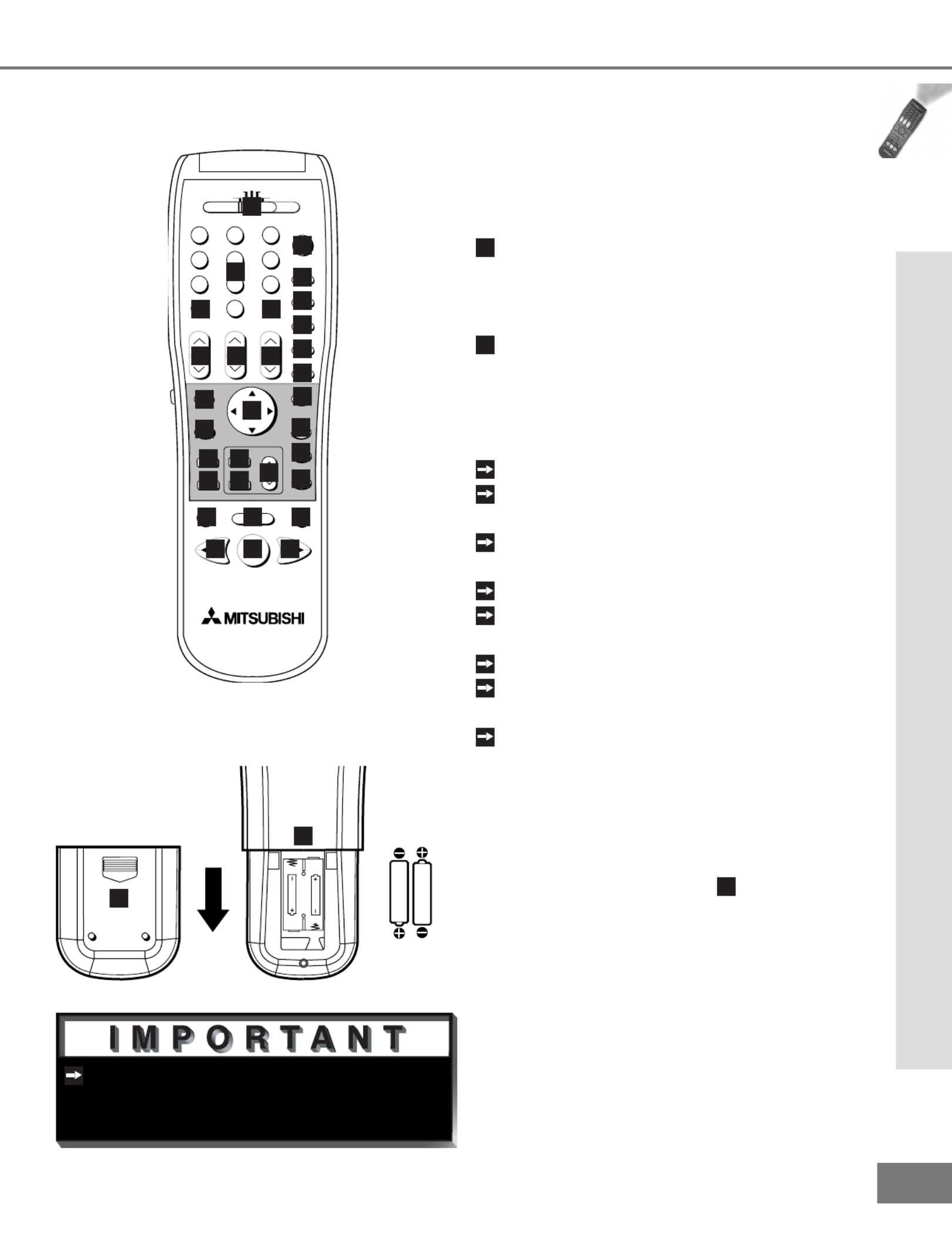
47
47
The remote control may return to its
initial setting when the batteries are
changed. You may need to reprogram.
Part IV: Operation
Operation
Installing the Batteries:
(Figure 2)
1
Remove the remote control’s back cover
by gently pressing the ridged tab in the
direction of the arrow and sliding off the
cover.
2
Load the batteries, making sure the
polarities (+) and (-) are correct.
For Best Results from the Remote Con-
trol:
Be within 20 feet of the equipment.
Do not press two or more buttons at the
same time unless instructed otherwise.
Do not allow to get wet or become
heated.
Avoid dropping on hard surfaces.
Do not use harsh chemicals to clean.
Use only a soft, lightly moistened cloth.
Do not mix new and old batteries.
Do not heat, take apart, or throw batter-
ies into re.
Use only AAA batteries.
Operating the Remote Control:
You can use the remote to control the TV,
CABLE/DBS, VCR, DVD, and AUDIO prod-
ucts. Select the product you want to control
by moving the slide switch (
1
of Figure 1) to
the appropriate position. The remote control
has been preset to operate the TV and other
Mitsubishi products. To program the remote
control to operate other products, see Use
of the Remote Control with Other A/V Prod-
ucts, pages 24-25.
Care and Operation
size AAA
batteries
Figure 2. Installing the batteries.
1
2
Remote Control Functions: Care and Operation
Figure 1. The remote control functions.
POWER
INFO
PAUSEREC
FF/FWDREW/REV PLAY
STOP
3
6
9
QV
VOLUME
GUIDE
EXCH
ENTER
CANCEL MENU
V-CHIP
FORMAT
PIP CH
1
7
SQV
4
INPUT
SLEEP
VIDEO
AUDIO
MUTE
2
5
8
0
CHANNEL
ADJUST
PIP INPUT
PIP/POP
HOME
TV AUDIO
CABLE/DBS DVD
VCR
HOME
THEATER
1
2
3
4
5
7
8
9
28
29
30
31
10
11
12
13
14
15
16
17
18
19
20
21
22
23
24
25
26
27
6

48
48
Part IV: Operation
Remote Control Functions: Channel Selection and Sleep Timer
Channel Selection
Enter three numbers (for channel 2,
press 002).
or
Press the channel number and ENTER
(for channel 2, press 2, then ENTER).
or
Enter the channel number and wait four
seconds. The TV will change automati-
cally.
Sleep Timer
Setting the Sleep Timer:
Press SLEEP on the remote control.
A message indicating the length of time
the sleep timer is to be set for is dis-
played on the TV screen.
Each press of SLEEP will increase
the time displayed by 30 minutes, until
the maximum value of 120 minutes is
reached.
After 5 seconds of inactivity, the mes-
sage will disappear.
Press SLEEP to view the remaining time
before the timer turns the TV off.
Canceling the Sleep Timer:
Press SLEEP to display the on-screen
message.
Press SLEEP repeatedly until OFF is
displayed.
After 5 seconds of inactivity, the mes-
sage box will disappear.
Channel Selection and Sleep Timer
The Mitsubishi System 4 Home Theater IR
Control is a special feature that makes it
easier to use your TV with a digital surround
sound A/V receiver. Once your equipment
is properly connected and set up, your TV
and digital A/V receiver will change inputs
together, to match your selected video input
with the corresponding audio input.
When you change inputs on your TV to
watch different video products, your TV will
send signals via your remote control and the
infrared emitters to your digital A/V receiver
to change inputs. You will automatically
hear the high quality digital surround sound
from digital products like your DVD player,
and high quality analog stereo or surround
sound from non-digital products like your
VCR.
Additionally, all IR remote signals from your
Mitsubishi remote or other manufacturers
remote will be passed through your TV to
your A/V devices. Your A/V devices can
be hidden or behind cabinet doors and con-
trolled by pointing the remote at the TV.
Remote Control Functions: System 4 Home Theater IR Control
Models VS-60719 and VS-70709

49
49
Other commands from your Mitsubishi
remote control, or other manufacturer’s
remote, will be passed through the TV.
Part IV: Operation
Remote Control Functions: System 4 Home Theater IR Control
Requirements for Operation
A/V devices connected as described on page 15.
Cable Box connected as on page 16 or Cable Box with an S-Video output connected as
on page 19, Connecting an S-Video Device.
TV connected to A/V receiver (TV Monitor Audio Out To A/V Receiver TV Input).
Remote Control programmed to operate your other A/V Devices by System 4 properly
activated (see pages 26-27).
IR emiters properly connected and placed (see page 20).
System 4 Home Theater IR Control
Operation (VCR as example)
To watch your VCR:
1
Turn on the TV and A/V Receiver.
2
Move slide switch to VCR.
3
Point remote at the TV and press the HOME THEATER button.
4
The TV and A/V Receiver should change to the appropriate inputs.
5
Operate the VCR.
System 4 allows for only one of the
following:
• Cable Box
• Satellite Receiver
Models VS-60719 and VS-70709

50
50
VCR
Cable Boxes and Satellite Receivers
A/V Receivers
Mitsubishi CD Players (not all functions for all models)
Mitsubishi A/V Receivers
DVD and Laser Disc Players (not all functions for all models)
POWER
POWER
CHANNEL up/down
ENTER (on some models)
STOPPAUSE
MENU
REW/REVPLAY FF/FWD
ADJUST up/down/left/right
(on some models)
VOLUME MUTE
GUIDE (on some models)
CANCEL (on some models)
POWER PLAY
REC STOP
PAUSE FF/FWD
REW/REVCHANNEL up/down
Mitsubishi VCRs will be compatible with additional buttons
0-9 Number Buttons (on some models)
POWER
STOP
PAUSE
REW/REV ENTER
PLAY ARROW up/down/left/right
(on some models)
CANCEL (on some models)
0-9 Number Buttons (on some models)
Direct Input Selection Buttons -use number buttons, SQV, and QV (on some models)
Part IV: Operation
Remote Control Functions: Special Functions
When your remote control has been Pro-
grammed to operate another manufacturer’s
product, the function performed on each
layer can vary. The most common functions
are:
Remote Control Functions: Operation of PIP
Picture-In-Picture (PIP) features allow you to
view Programming in different ways. While
watching the main screen, you can display
programs from other channels and other
inputs. To see which inputs can and cannot
be used together, see How Connections
Affect the PIP - Table 1, page 14.
Activating the PIP
Figures 1-5 on following page)
Press PIP to choose a display format. With
each press of the PIP button on the TV
remote control (within 3 seconds of each
other), the PIP will cycle through the follow-
ing display options.
1
PIP
2
Eleven PIP
3
Four PIP
To turn PIP off, wait at least 10 seconds, and
press the PIP button. The next time you
activate PIP, the last used PIP format will be
displayed rst.
Special Functions and Operation of PIP

51
51
Part IV: Operation
Remote Control Functions: Operation of PIP
Changing PIP Inputs
Press PIP INPUT to cycle through available
inputs. To see which inputs can and cannot
be used together, see How Connections
Affect the PIP - Table 1, page 14.
Changing PIP Channels
Press PIP CH to scroll up and down through
memorized channels on Ant-A, and Ant-B.
Exchanging Program Images
Press ENTER/EXCH to exchange the main
picture and the PIP picture.
Moving PIP and Four PIP Image
Press ADJUST , , , or to move the PIP
display anywhere on the main screen, or to
select each of the Four PIP locations.
PIP Size (Figure 1)
Press PIP SIZE to cycle through the ve
sizes available: 1/4, 1/6, 1/9, 1/12, and 1/16.
Eleven PIP and Four PIP Automatic
Switching (Figures 2 and 3)
When viewing either Eleven PIP or Four PIP,
the TV will cycle through memorized chan-
nels. Press PAUSE to retain the current live
video and discontinue automatic switching.
Freeze the PIP
Press PAUSE to freeze the PIP. Press
PAUSE again to return to a “live” image.
Main Image Still Frame
When viewing the main image, press PAUSE
and a 1/9 PIP window will open with a dis-
play of a still frame from the main image.
WARNING: See , page 21.Important Notes
PIP Audio Signal
For PIP audio connection illustration, see
Back Panel Functions, page 13. Volume for
the PIP AUDIO OUTPUT is controlled by the
amplier or wireless headphones.
Operation of PIP
1
2
3
Figure 1. PIP window sizes.
Figure 2. 11 PIP window sizes.
Figure 3. 4 PIP window sizes.

53
53
53
53
53
When the ENTER button on the remote
control is pressed, ALL custom settings
will be erased and reset to the factory
defaults. This operation CANNOT be
undone.
Reset System Defaults Menu
Reset System Defaults Menu
(Figure 1)
To access the Reset System Defaults
menu screen, you must rst be out of any
active menu screen. You can do this by
pressing the HOME button on the remote
control. Press the MENU button followed
by number buttons 1, 2, and then 3, on
the remote control. This sequence will
activate the Reset System Defaults menu
screen. Pressing the ENTER button on
the remote control will reset all option
settings back to the factory defaults.
Pressing the HOME or MENU buttons on
the remote control will remove the Reset
System Defaults menu screen and apply
no changes to your system settings.
Reset System Defaults Menu
Reset System Defaults Instructions
Have Been Filed for Future Reference
Figure 1. Reset System Defaults menu.


Termékspecifikációk
| Márka: | Mitsubishi |
| Kategória: | Televíziók |
| Modell: | VS-55609 |
Szüksége van segítségre?
Ha segítségre van szüksége Mitsubishi VS-55609, tegyen fel kérdést alább, és más felhasználók válaszolnak Önnek
Útmutatók Televíziók Mitsubishi

10 Július 2024
7 Július 2024
6 Július 2024
4 Július 2024
1 Július 2024
Útmutatók Televíziók
- Televíziók Samsung
- Televíziók Sony
- Televíziók LG
- Televíziók Philips
- Televíziók Panasonic
- Televíziók JVC
- Televíziók Sharp
- Televíziók Clatronic
- Televíziók Hitachi
- Televíziók Daewoo
- Televíziók AKAI
- Televíziók Sanyo
- Televíziók Sylvania
- Televíziók Marquant
- Televíziók Superior
- Televíziók EKO
Legújabb útmutatók Televíziók

16 Január 2025
14 Január 2025
16 Október 2024
16 Október 2024

16 Október 2024
16 Október 2024
15 Október 2024

14 Október 2024
13 Október 2024

13 Október 2024