Használati útmutató Manhattan 1200AC
Olvassa el alább 📖 a magyar nyelvű használati útmutatót Manhattan 1200AC (64 oldal) a router kategóriában. Ezt az útmutatót 9 ember találta hasznosnak és 2 felhasználó értékelte átlagosan 4.5 csillagra
Oldal 1/64
WIRELESS
ROUTER
USER MANUAL
MODELS 525459, 525466,
525480
MH-525459/525466/525480-UM-0713-01
150N Model 505459
300N Model 505466
1200AC Model 505480

2
Thank you for purchasing this Manhattan® Wireless Router: Model 525459 (150N
4-Port), Model 525466 (300N 4-Port) or Model 525480 (1200AC 4-Port).
The latest in wireless networking, these Wireless Routers serve multiple purposes —
an access point for your wireless network, a four-port router for hard-wiring Ethernet
devices — and bring it all together so that the devices can access a high-speed
Internet connection.
Detailed instructions in this user manual make installation reasonably quick and
simple so you’ll soon be enjoying the benets of these and more popular features:
• Network link speed of up to 150 Mbps for Model 525459, 300 Mbps for Model
525466 and 867 Mbps for Model 525480 (at 5 GHz)
• Supports WMM function to meet the multimedia data bandwidth requirement
• Supports Wi-Fi Protected Setup (WPS)
• Supports WEP and WPA/WPA2 (TKIP and AES) data encryption
• Auto MDI/MDI-X support
• DHCP server assigns IP addresses for all LAN users
• DHCP server supports static lease management
• Supports virtual server, port forwarding and DMZ (demilitarized zone)
• Supports DDNS (dynamic DNS)
• Supports UPnP (Universal Plug and Play)
• Integrated anti-DOS rewall
• QoS (Quality of Service) bandwidth management
• VPN Passthrough
• Easy installation through Web-based user interface
• Three-Year Warranty
Package Contents
• Wireless 150N 4-Port Router, Wireless 300N 4-Port Router or Wireless 1200AC
Router
• Quick install guide, plus user manual on CD
• Power adapter
• Ethernet Cat5 RJ45 cable: 1.0 m (3 ft.)
NOTE: Some screen images have been modied to t the format of this manual.
Hardware sections 1.1 and 1.2 feature images of the 150N Router: Displays and
components for the 300N Router are similar.
For specications, refer to each model’s datasheet at manhattan-products.com.

3
TABLE OF CONTENTS
TABLE OF CONTENTS
section page section page
1 HARDWARE ........................................... 5
1.1 Front Panel Display .......................... 5
1.2 Back Panel Display 5 ..........................
2 SYSTEM & NETWORK SETUP 6 .............
2.1 Connecting the Router .....................6
2.2 Obtaining an IP Address .................. 6
2.2.1 Windows XP Setup ....................7
2.2.2 Windows Vista/7 Setup ..............9
2.2.3 Router IP Address Lookup ....... 10
2.3 Quick Setup ................................... 13
2.3.1 Cable Modem .......................... 14
2.3.2 Fixed IP xDSL (Static IP) ......... 15
2.3.3 PPPoE xDSL ...........................16
2.3.4 PPPTP xDSL ........................... 16
2.3.5 L2TP xDSL .............................. 18
2.3.6 Telstra BigPond ....................... 18
2.4 Basic Setup .................................... 19
2.4.1 Time Zone / Auto-Synch ..........20
2.4.2 Changing Mngmt. Password ....20
2.4.3 Remote Management .............. 21
2.5 WAN Setup ....................................22
2.5.1 Dynamic IP ..............................23
2.5.2 Static IP ...................................23
2.5.3 PPPoE ..................................... 24
2.5.4 PPPTP .....................................24
2.5.5 L2TP ........................................25
2.5.6 Telstra BigPond ....................... 26
2.5.7 DNS .........................................26
2.5.8 DDNS ......................................27
2.6 LAN Conguration .........................28
2.6.1 LAN IP ..................................... 28
2.6.2 DHCP Server ........................... 29
2.7 WLAN Conguration ...................... 30
2.7.1 Basic Wireless Settings ........... 31
2.7.2 Advanced Wireless Settings .... 32
2.7.3 Wireless Security .....................33
2.7.4 Wireless Access Control .......... 37
2.7.5 WPS ........................................38
2.7.6 Security Tips ............................39
3 ADVANCED FUNCTIONS .................... 41
3.1 QoS ................................................ 41
3.1.1 Basic QoS Settings .................. 41
3.1.2 Adding a new QoS Rule .......... 42
3.2 NAT ................................................ 43
3.2.1 Port Forwarding .......................44
3.2.2 Virtual Server ...........................45
3.2.3 Port Mapping ...........................46
3.2.4 UPnP ....................................... 47
3.2.5 ALG ......................................... 47
3.3 Firewall ...........................................48
3.3.1 Access Control ........................48
3.3.2 Add PC ....................................50
3.3.3 URL Blocking ........................... 51
3.3.4 DoS Attack Prevention.............52
3.3.5 DMZ .........................................53
4 ADDITIONAL FUNCTIONS .................. 55
4.1 Status .............................................55
4.1.1 Internet Connections ............... 55
4.1.2 Device Status ..........................56
4.1.3 System Log ..............................56
4.1.4 Security Log ............................56
4.1.5 Active DHCP Client .................57
4.1.6 Statistics ..................................57
4.2 Tools ..............................................57
4.2.1 Conguration Tools ..................57
4.2.2 Firmware Upgrade ................... 58
4.2.3 Reset .......................................59
5 TROUBLESHOOTING .......................... 60
6 GLOSSARY .......................................... 62

4
SAFETY GUIDELINES
SAFETY GUIDELINES
For the protection of equipment users and connected devices, follow these safety
guidelines:
1. This router is designed for indoor use only; do not place this router outdoors.
2. Do not place this router in hot or humid environments.
3. Do not yank any connected cables.
4. Firmly secure this device if it’s placed at any signicant height.
5. Router accessories such as the antenna and power supply should be considered
dangerous when handled by children under the age of 3. Keep this device out
of the reach of children.
6. The router will become hot when used for long time. This is normal and is not a
malfunction, but keep the router away from paper, cloth and other ammable
materials.
7. There are no user-serviceable parts inside the router. If the router is not working
properly, contact your dealer (place of purchase) and ask for help. Do not
disassemble the router, as doing so will void the warranty.
8. If the router falls into water while it’s powered on, pick it up with your do not
hands. Disconnect the power before you do anything, or contact an
experienced technician for help.
9. If you smell something strange, or if you see some smoke coming from the
router or power supply, remove the power supply or switch the electrical power
off immediately and call the dealer for help.

1 HARDWARE
1.1 Front Panel Display
LED Status Description
PWR On Router is powered on.
WLAN On Wireless network is switched on or WPS mode is on.
Flashing Wireless LAN activity (transferring or receiving data).
WAN / On WAN port is connected.
WAN LNK/ACT Flashing WAN activity (transferring or receiving data).
LAN (1-4) On LAN port is connected.
LAN LNK/ACT Flashing LAN activity (transferring or receiving data).
2.4G On 2.4GHz Wireless WPS function is enabled.
Flashing Wireless LAN activity (transferring or receiving data).
5G On 5GHz Wireless WPS function is enabled.
Flashing Wireless LAN activity (transferring or receiving data).
1.2 Back Panel Display
Feature Description
Radio Activate or deactivate the wireless function with this ON/OFF switch.
Reset/ Reset the router to factory default settings (clear all settings) or start the
WPS WPS function. Press and hold for 10 seconds to restore all settings to
factory defaults; press for less than 5 seconds to start WPS.
1-4 Local Area Network (LAN) ports 1 to 4.
WAN Wide Area Network (WAN/Internet) port.
5VDC Connects tthe A/C power adapter (5V DC).
5
HARDWARE
150N / 300N 1200AC
5VDC
1200AC
150N / 300N
5VDC
RADIO
WPS
WPS
WAN
WAN
4 3 2 1
4 3 2 1

6
SYSTEM & NETWORK SETUP
2 SYSTEM & NETWORK SETUP
2.1 Connecting the Router
1. Connect your DSL or cable modem to the WAN port of the router using the
provided RJ45 Ethernet cable. NOTE: Standard modems provided by Internet
service providers come with at least one LAN/Ethernet port, which connects to
the WAN port of the router.
2. Connect all your computers and network devices (network-enabled components
like game consoles, network media players, network storage units or LAN
switches) to the LAN ports (1-4) of the router.
3. Connect the A/C power adapter to the wall socket, and then connect it to the
power jack of the router.
4. Check all LEDs on the front panel. The PWR LED should be on, and the WAN
and LAN LEDs should be on if the computer or network device connected to the
corresponding router port(s) is powered on and correctly connected.
2.2 Obtaining an IP Address
Before you can connect to the router and start conguration procedures, your
computer must be able to obtain an IP address automatically (that is, to use a
dynamic IP address). This is the default setup for any standard Windows computer,
and it normally is not required to make any changes.
1. With your computer connected to a LAN port
on the router, activate the network connection.
Start your Web browser and open
http://manhattanrouter to display a login
window (right).
2. Enter “admin” as the username and “1234” as
the password, then click “OK.”
213
Example: 150N
7
SYSTEM & NETWORK SETUP
NOTE: If this procedure is successful, skip the following subsections and proceed
to 2.3 Using Quick Setup. If the above procedure doesn’t result in your obtaining
an IP address, or if you know that your computer has a static IP address setup,
follow the steps in the appropriate subsection below.
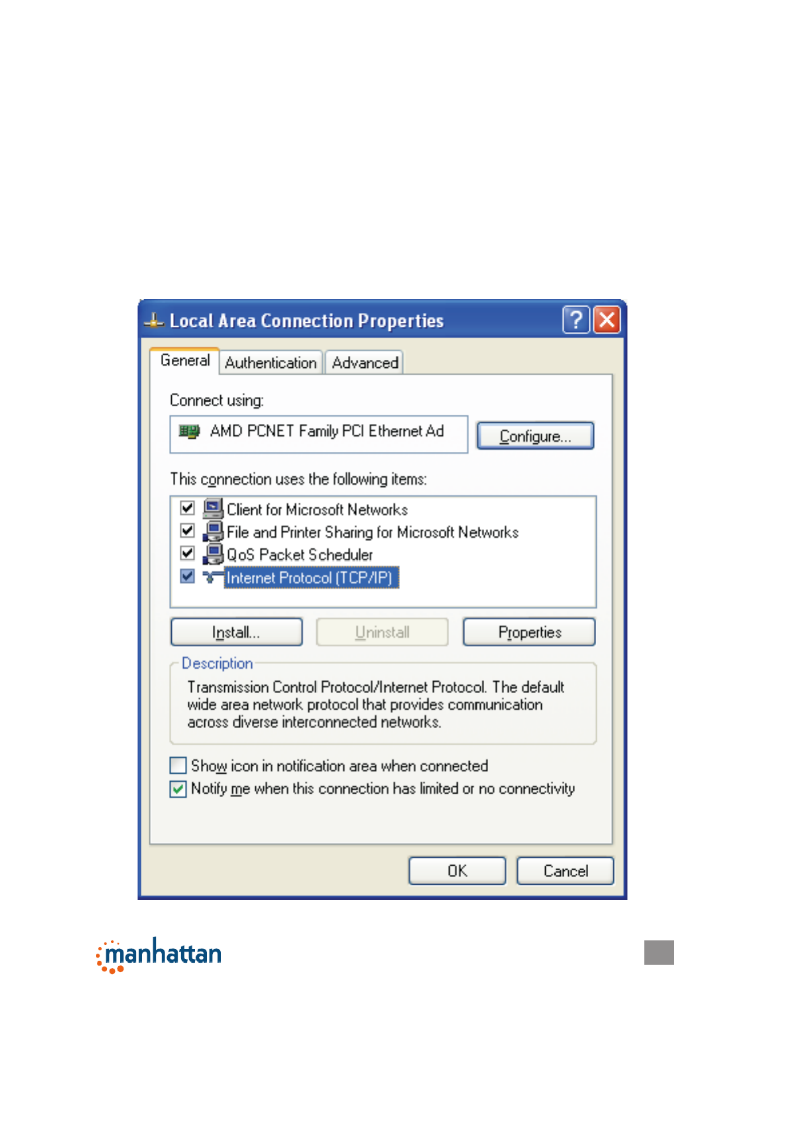
2.2.1 Windows XP IP Address Setup
1. Click “Start,” then go to the control panel. Double-click the Network & Internet
Connections icon, then click “Network Connections” and double-click “Local
Area Connection” to display the Local Area Connection Status window. Click
“Properties.”
8
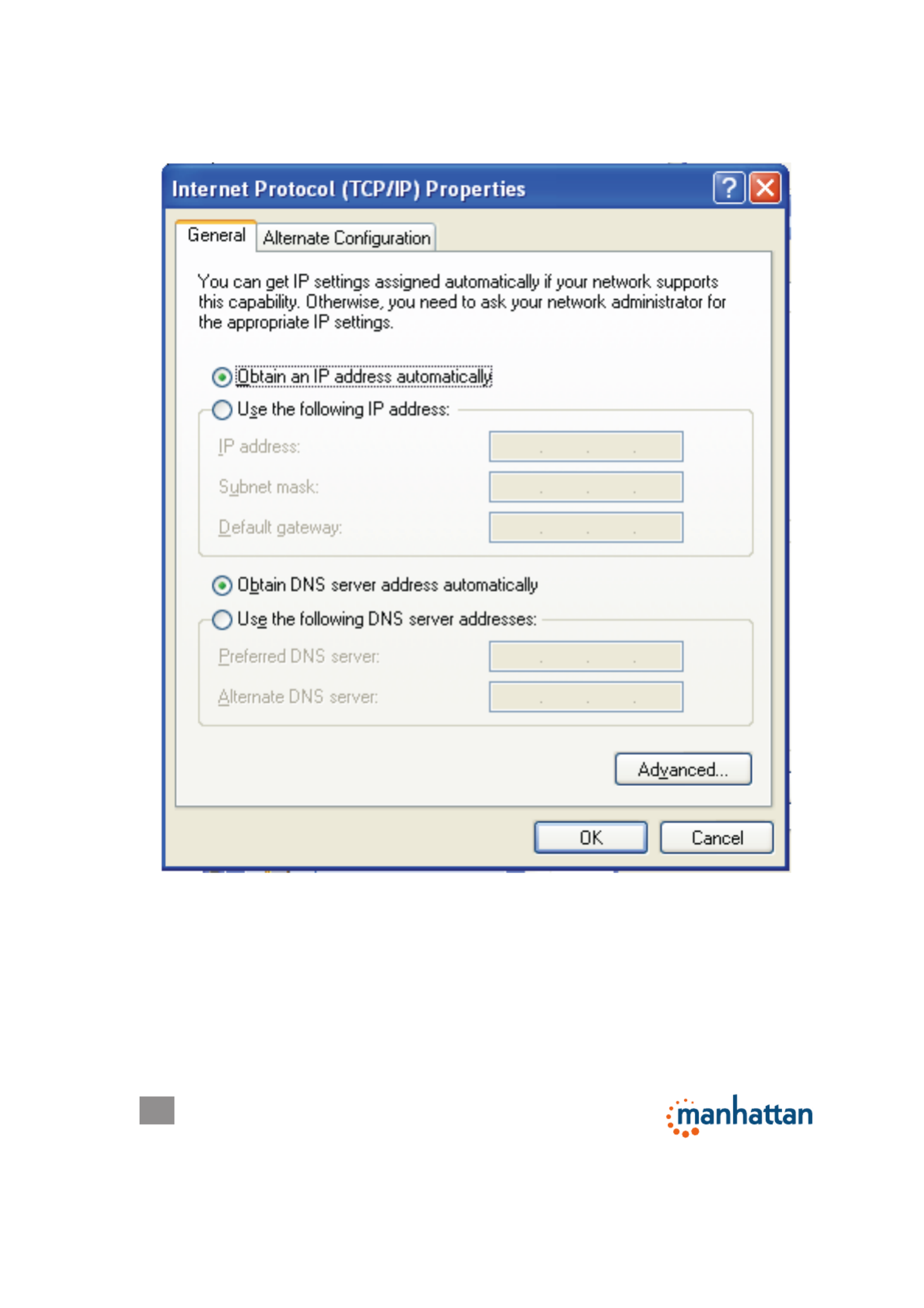
SYSTEM & NETWORK SETUP
2. Select “Obtain an IP address automatically” and “Obtain DNS server address
automatically,” then click “OK.”

9
SYSTEM & NETWORK SETUP
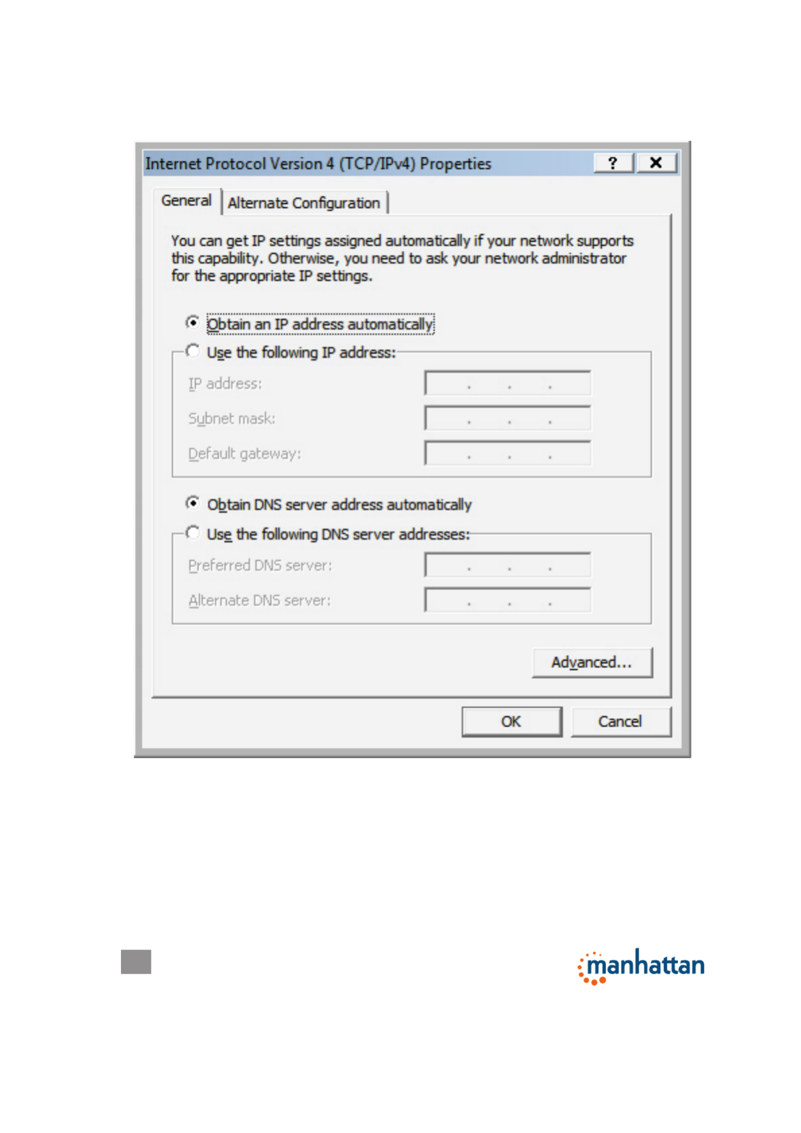
2.2.2 Windows Vista/7 IP Address Setup
1. Click “Start,” then go to the control panel. Click “View Network Status and Tasks,”
then click “Manage Network Connections.” Right-click “Local Area Network,”
then select “Properties.” With the Local Area Connection Properties window
displayed, select “Internet Protocol Version 4 (TCP / IPv4),” and click “Properties.”
10
SYSTEM & NETWORK SETUP
2. Select “Obtain an IP address automatically” and “Obtain DNS server address
automatically,” then click “OK.”
2.2.3 Router IP Address Lookup
1. After the IP address is set up, click “Start” at the bottom-left of the desktop, then
click “Run.”

11
SYSTEM & NETWORK SETUP
2. With the Run window displayed,
enter “cmd” in the “Open:” text eld,
then click “OK.”

12
SYSTEM & NETWORK SETUP
3. Enter “ipcong,” then press <Enter>. The IP address displays, followed by the
default gateway. In the example below, the IP address of the router is
192.168.2.1.
NOTE: If the IP address of the gateway is not displayed, or if the address begins
with 169, recheck the network connection between your computer and the router,
and re-check each step of the network setup procedure.
4. Once your computer has obtained an IP address from the router, open your Web
browser and enter the IP address of the router into the address bar. When the
login window displays (see 2.2 above), enter the username (“admin”) and the
password (“1234”). Press “OK” to display the router’s Web management interface.
NOTE: If you can’t see the Web management interface and you’re being prompted
to enter the user name and password again, it means you didn’t enter the correct
username and password. Re-type the username and password. If you’re certain
that the username and password are correct, refer to 4-2 Troubleshooting to
perform a factory reset to set the password back to the default value.
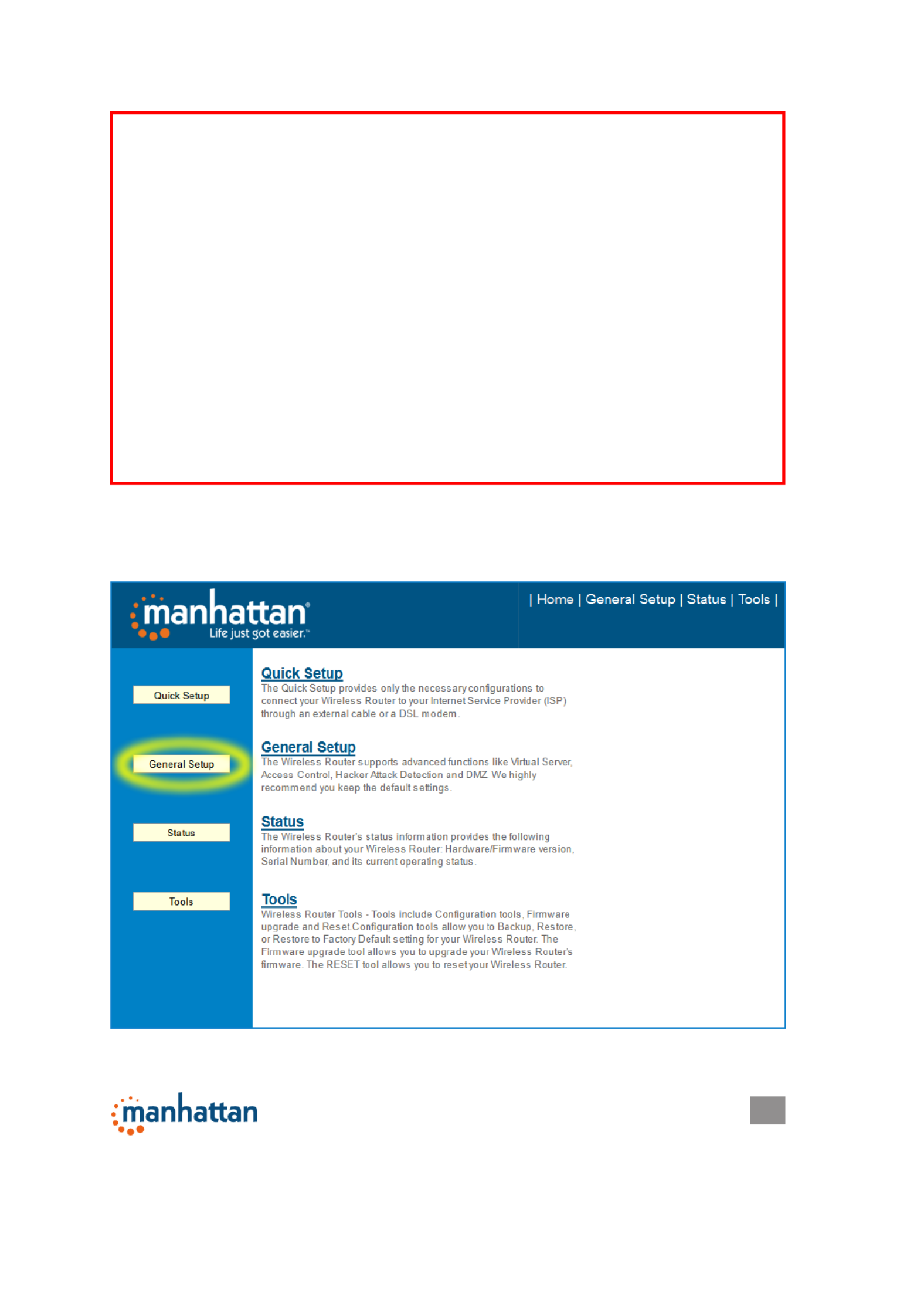
TIP: This page (see below) shows the four primary setting 2.3 Quick Setup
categories: QuickSetup, General Setup, Status and Tools. You can jump to
another menu category directly by clicking the link at the top-right of each screen.

13
SYSTEM & NETWORK SETUP
2.3 Quick Setup
The Quick Setup procedure lets you congure all the settings required for quick
Internet access.
.
The initial Quick Setup screen presents time settings.
Set Time Zone — Use the drop-down menu to select your time zone.
Time Server Address — Enter the IP address/hostname of the time server. This
isn’t normally required, but if the default time server (NTP) should go ofine, you
can obtain a new NTP server from the list at http://www.ntp.org.
Daylight Savings — If your locale uses Daylight Saving, activate “Enable Function”
and select the duration using the drop-down menus.

14
SYSTEM & NETWORK SETUP
Click “Next” to continue to the next screen of the Quick Setup procedure, where
you select the broadband (Internet connection) type you use.
There are six types of Internet connections available, as explained below: Cable
Modem, Fixed IP xDSL, PPPoE xDSL, PPTP xDSL, L2TP xDSL and Telstra
BigPond. Cable Modem and PPPoE xDSL are the most common, but if you’re not
sure which type of service you have, simply contact your Internet service provider
(ISP) to nd out. You won’t be able to connect to the Internet if you choose the
wrong type during the router setup. NOTE: DSL Internet Service Providers
normally operate using the PPPoE protocol; thus, PPPoE xDSL should be the
broadband type. However, in recent years more DSL ISPs provide customers with
DSL modems that handle the PPPoE portion of Internet access automatically. In
such cases, you need to select Cable Modem as your broadband type even if you
have a DSL service.
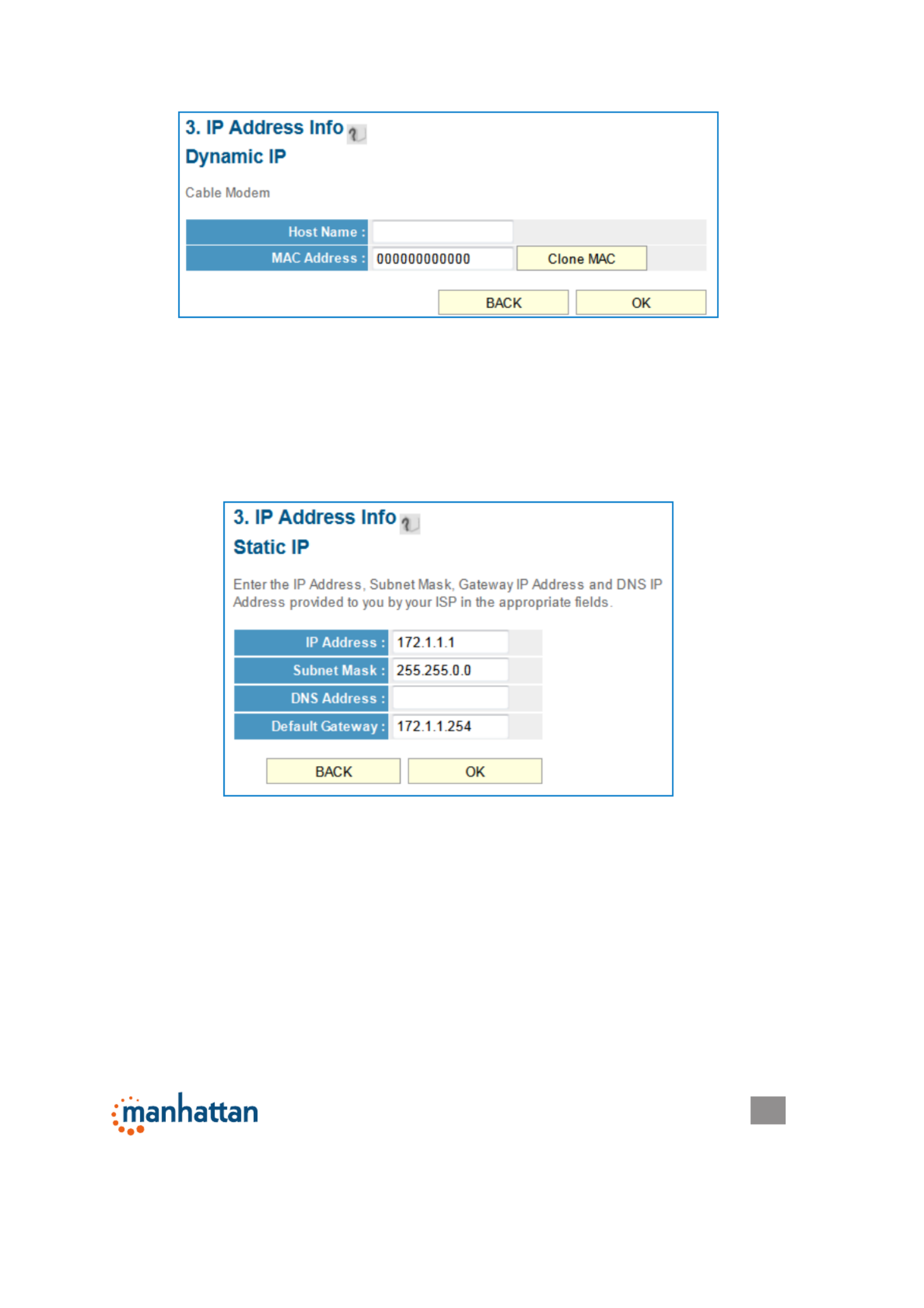
2.3.1 Setup Procedure for Cable Modem (Dynamic IP)
Host Name — Input the host name of your computer. This is optional, and is only
required if your service provider asks you to do so.
On all screens, click “Apply” (if such button appears at the bottom) to submit any
option or conguration changes. Click “Back” to return to the previous screen.
Click “Cancel” to undo any changes you’ve made on that screen. Click “Next” or
“OK” to proceed to the next screen.
15
SYSTEM & NETWORK SETUP
MAC address — Enter the MAC address of your computer here if your service
provider only permits a computer with a certain MAC address to access the
Internet. If you’re using a computer used to connect to the Internet via cable
modem, you can simply click “Clone Mac address” to ll in the MAC address
eld with the MAC address of your computer.
2.3.2 Setup Procedure for Fixed IP xDSL (Static IP)
IP address — Enter the IP address assigned by your ISP.
Subnet Mask — Enter the subnet mask assigned by your ISP.
DNS address — Enter the IP address of the DNS server provided by your ISP.
Service Provider Gateway Address — Enter the gateway IP address provided by
your ISP.
NOTE: You can choose this Internet connection method if your service provider
assigns a xed IP address (also know as a static address) to you, and doesn’t use
DHCP or PPPoE protocol. Contact your service provider for further information.

16
SYSTEM & NETWORK SETUP
2.3.3 Setup Procedure for PPPoE xDSL
User Name — Enter the username assigned by your ISP.
Password — Enter the password assigned by your ISP.
Service Name — Provide a name for this Internet service. (optional)
MTU — Enter the MTU value of your network connection. NOTE: Use the default
value unless your ISP species otherwise.
Connection Type — Select one of the three connection types in the drop-down
menu:
• “Continuous” keeps the Internet connection alive and does not disconnect.
This is the preferred choice for always-on / at-rate Internet services.
• “Connect on Demand” only connects to the Internet when there’s a connect
attempt. This is the preferred choice for all users who have paid-per-minute
or per-transferred-data Internet service.
• “Manual” only connects to the Internet when “Connect” is selected, and
disconnects when “Disconnect” is selected.
Idle Time Out — Specify the time to shut down the Internet connection after no
Internet activity is detected. This option is only available when the connection
type is Connect on Demand.
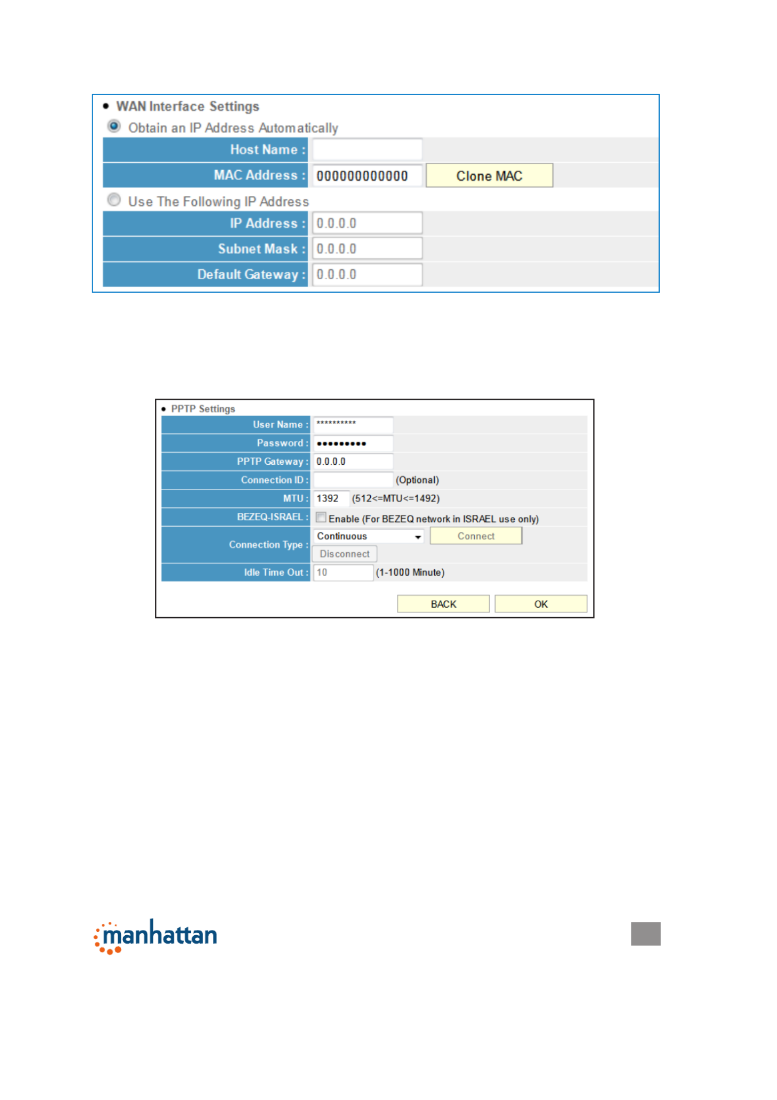
2.3.4 Setup Procedure for PPTP xDSL
PPTP xDSL requires two groups of settings: the WAN interface settings (to set up
IP address) and PPTP settings (PPTP username and password).
In the WAN Interface Settings panel, select how you obtain an IP address from
your service provider: “Obtain an IP address automatically” or “Use the following
IP address” (i.e., a static IP address). The WAN interface settings must be
17
SYSTEM & NETWORK SETUP
correctly entered; otherwise, the Internet connection will fail even if the PPTP
settings are correct. Contact your ISP if you don’t know how you should ll in
these elds.
The PPTP Settings panel presents these options:
User Name — Enter the username assigned by your ISP.
Password — Enter the password provided by your ISP.
PPTP Gateway — Enter the IP address of PPTP gateway assigned by your ISP.
Connection ID — Enter the connection ID. (optional)
MTU — Enter the MTU value of your network connection. NOTE: Use the default
value unless your ISP species otherwise.
Connection Type — Select one of the three connection types in the drop-down
menu (see PPPoE above):
Idle Time Out — Specify the time to shut down the Internet connection after no
Internet activity is detected. This option is only available when the connection
type is Connect on Demand.
NOTE: Enable BEZEQ-ISRAEL only if you’re using that network provider.
18
SYSTEM & NETWORK SETUP
2.3.5 Setup Procedure for L2TP xDSL
L2TP is another popular connection method for xDSL and other Internet connection
types, and all required setting items are the same as the PPTP connection (see
section 2.3.4 above).
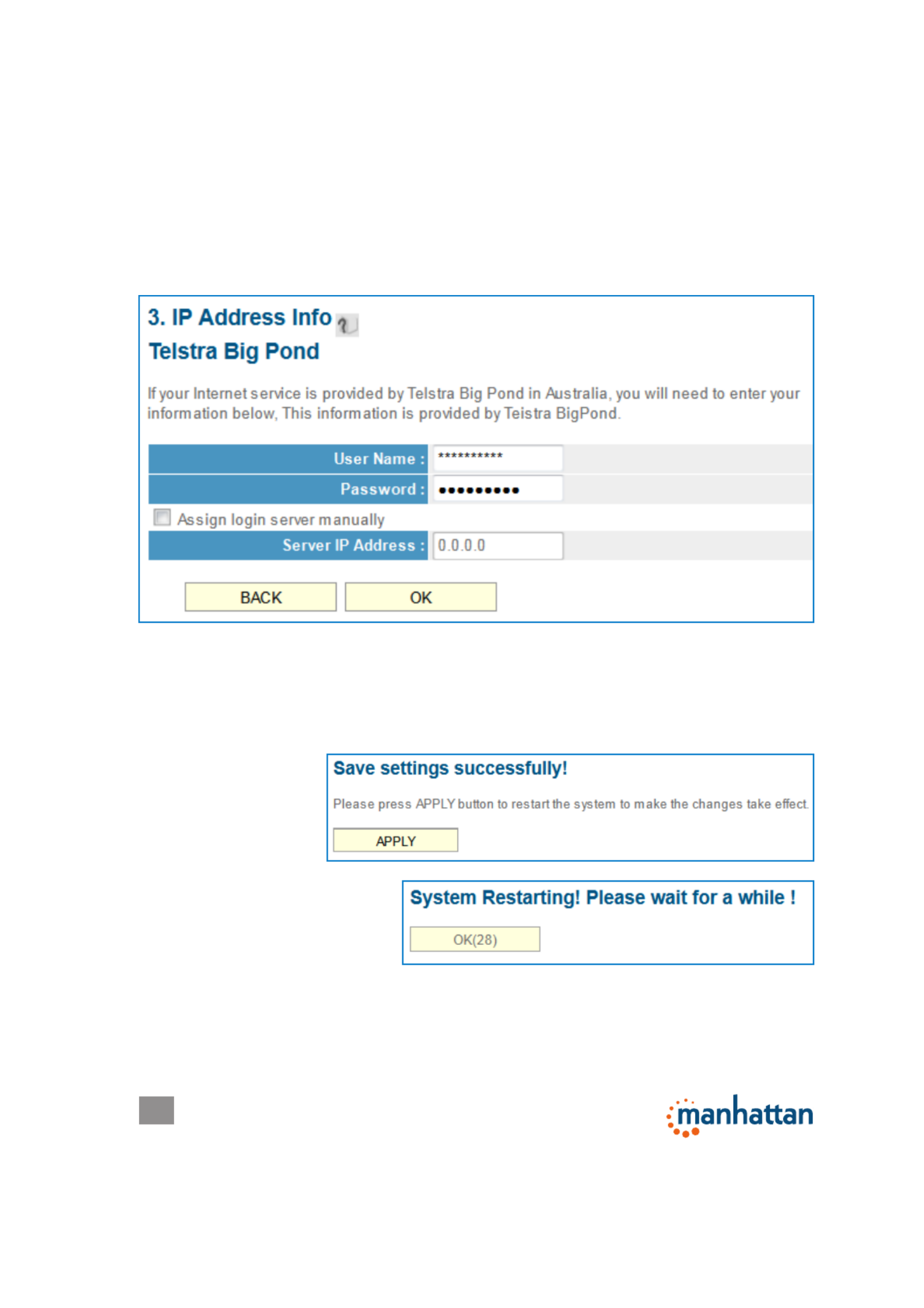
2.3.6 Setup Procedure for Telstra BigPond
This procedure is only for the Telstra BigPond network service in Australia.
User Name — Enter the username assigned by Telstra.
Password — Enter the password assigned by Telstra.
Assign login server manually — Select to choose the login server by yourself.
Server IP Address — Enter the IP address of the login server.
When all settings are
nished (and after you
click “OK”), you’ll see
this message (right)
on your Web browser.
Click “Apply” to restart the
router. You’ll see a second
restart message (right).
Wait for about 30 seconds, then click “OK.” You’ll be forwarded to the router’s Web
management interface. The router is now running with the new settings, and, if all
information entered is correct, you can now access the Internet.
19
SYSTEM & NETWORK SETUP
2.4 Basic Setup
This section explains how to change the time zone, password and remote
NOTE TO DSL USERS
While PPPoE is the most common way to connect to DSL Internet service, it still
may be necessary to enable “Cable Modem” in the Broadband settings. Below are
examples for using Cable Modem instead of xDSL PPPoE, even if your Internet
service is a DSL service.
• Your ISP has given you a so-called “modem-router” instead of a simple modem.
• Your ISP has not given you a username and password for PPPoE login (implying
that it is not required).
• When your computer is connected directly to the modem, the computer obtains
an IP address which is in the private IP network range (192.168.xxx.yyy, 10.xxx.yyy,
172.16.xxx.yyy).
• You can connect to the Internet with your computer connected directly to the
modem without using a dialer program asking for a username and password.
• If attempts to utilize PPPoE xDSL fail repeatedly, you should activate “Cable
Modem” as a troubleshooting step.

20
SYSTEM & NETWORK SETUP
management settings. Start your Web browser and log on to the router’s Web
management interface by opening http://manhattanrouter, then click the “General
Setup” button on the left.
2.4.1 Time Zone and Time Auto-Synchronization
Click the “System” menu on the left of the Web management interface, then click
“Time Zone.” You’ll be prompted to select a time zone from the “Set time zone”
drop-down menu and enter the IP address or host name of the time server. If you
want to enable the Daylight Saving setting, check the “Enable Function” box and
set the duration of Daylight Saving.
Click “Apply” and this message
will display. Click “Continue” to
save the settings and make
additional changes; click
“Apply” to save the settings and
restart the router so the
settings will take effect after it reboots.
2.4.2 Changing the Management Password
The default password of this router is 1234, and it’s displayed on the login prompt
when accessed from the Web browser. There’s a security risk if you don’t change
the default password, since everyone can see it. This is very important when you
have the wireless function enabled. To change the password, click the “System”
menu on the left of the Web management interface, then click “Password
Settings.”
Current Password — Enter the current password (for example, 1234).
New Password — Enter the new password.
Conrm Password — Enter the new password again.
21
SYSTEM & NETWORK SETUP
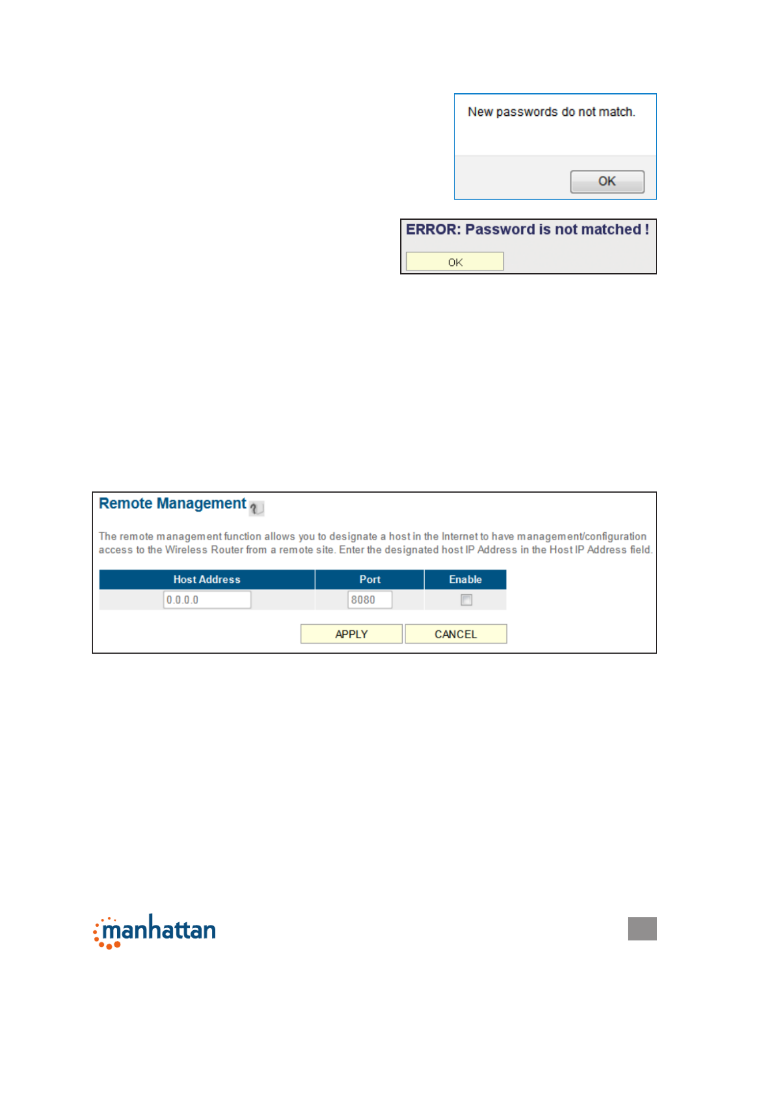
If the passwords entered in the “New Password”
and “Conrmed Password” elds aren’t the same,
you’ll see the message at right. Re-enter the new
password.
If you see the error message at right, it means the
content in the “Current Password” eld is
wrong. Click “OK” to go back to the previous
menu, and try entering the current password
again. If the current and new passwords are
correctly entered, click “Apply” and you’ll be
prompted to log in again. Enter the
new password and enter “admin” for the username.
2.4.3 Remote Management
This router by default does not allow management access from the Internet to
prevent possible security risks (especially when you have dened a weak password
or didn’t change the default password). However, you can still manage this router
from a specic IP address by enabling the Remote Management function.
Click the “System” menu on the left of Web management interface, then click
“Remote Management.” The screen below will display on your Web browser.
Host Address — Enter the IP address of the remote host you want to initiate
management access..
Port — You can dene the port number through which this router should expect an
incoming request. If you’re providing a Web service (default port number is 80),
you should try to use another port number. You can use the default port setting
(8080) or something like 32245 or 1429 (any integer between 1 and 65534)..
Enabled — Select the eld to start the conguration.
Click “Apply,” then either click “Continue” to save the settings and make additional
changes or click “Apply” again to save the settings and restart the router so the
settings will take effect after it reboots.

22
SYSTEM & NETWORK SETUP
2.5 Setting Up an Internet Connection (WAN Setup)
The Internet connection setup can be done by using the Quick Setup menu
described in section 2-3. However, you can set the WAN connections up by using
the WAN conguration menu. You can also program advanced functions like DDNS
(Dynamic DNS) here.
Click the “WAN” menu on the left of the Web management interface, then select
an Internet connection method based on the type of connection you’re using. You
can either click the connection method in the left-side menu or select it from the
main panel in the center (which requires that you then click “More Conguration”
to continue).
NOTE: To manage this router from another computer on the Internet, you need to
input the IP address and port number of this router. If your Internet service provider
assigns you a static IP address, it will not be a problem; but if the IP address your
service provider assigns will vary every time you establish an Internet connection,
this will be a problem. Either ask your ISP to give you a static IP address, or use
a dynamic DNS service like DDNS. (See section 2.5.8 DDNS Client below for
details.)
NOTE: The default port number the Web browser will use is 80. If the “Port” setting
on this page is not 80, you need to assign the port number in the address bar of
the Web browser manually. For example, if the IP address of this router is 1.2.3.4,
and the port number you set is 8888, you need to enter http://1.2.3.4:8888 in the
address bar of the Web browser.

23
SYSTEM & NETWORK SETUP
2.5.1 Setup Procedure for Dynamic IP
Host Name — Enter the host name of your computer. (This is optional and is only
required if your service provider asks you to do so.)
MAC Address — Enter the MAC address of your computer if your service provider
only permits a computer with a certain MAC address to access the Internet. If
you’re using the computer to connect to the Internet via cable modem, you can
simply click “Clone MAC” to ll the “MAC Address” eld with the MAC address
of your computer.
2.5.2 Setup Procedure for Static IP
IP Address — Enter the IP address assigned by your service provider.
Subnet Mask — Enter the subnet mask assigned by your service provider.
Default Gateway — Enter the IP address of the gateway server assigned by your
service provider.
24
SYSTEM & NETWORK SETUP
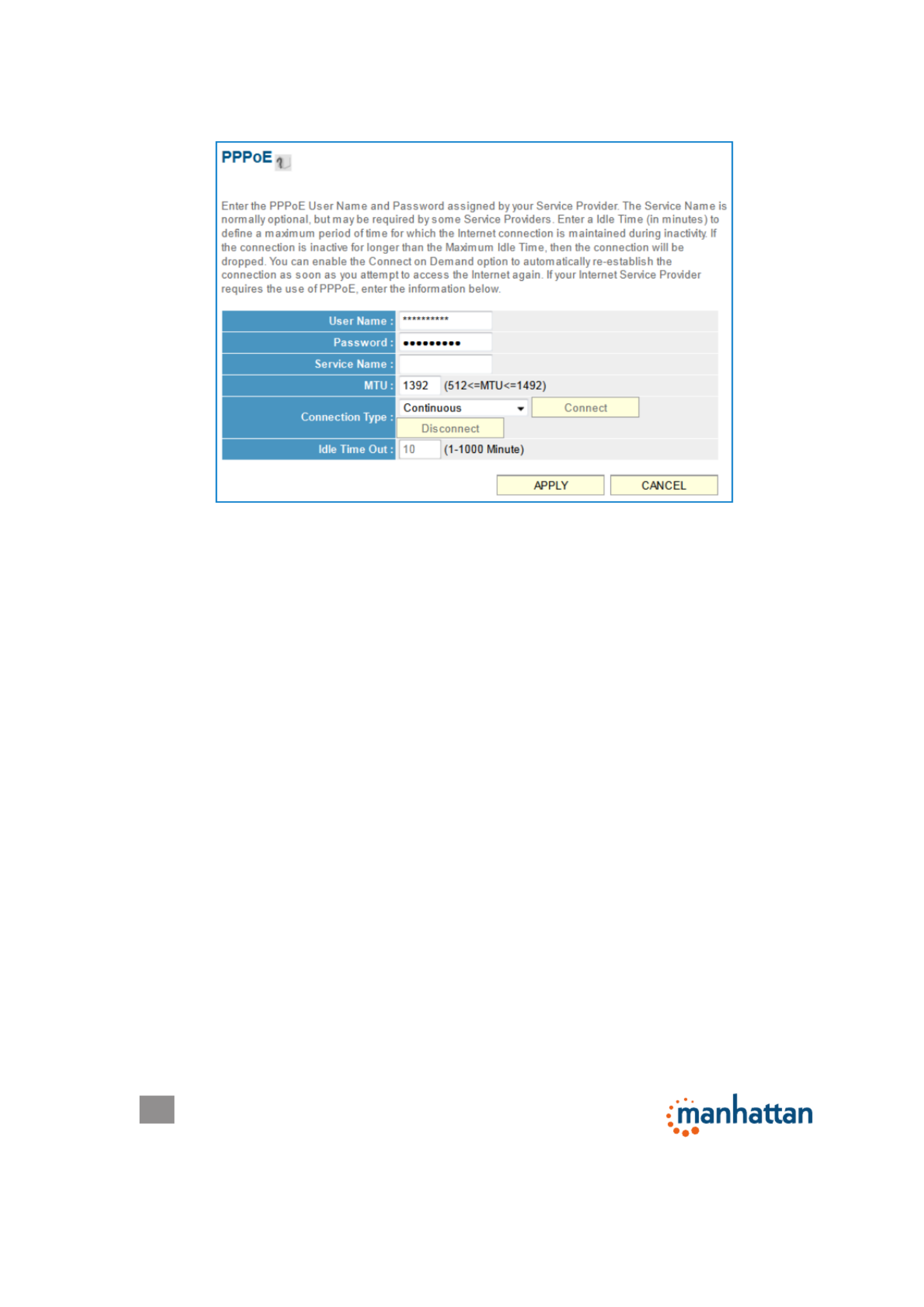
2.5.3 Setup Procedure for PPPoE
User Name — Enter the user name assigned by your Internet service provider.
Password — Enter the password assigned by your Internet service provider.
Service Name — Enter a name for this Internet service. (optional)
MTU — Enter the MTU value of your network connection. NOTE: Use the default
value unless your ISP species otherwise.
Connection Type — Select one of the three connection types in the drop-down menu:
• “Continuous” keeps the Internet connection alive and does not disconnect.
This is the preferred choice for always-on / at-rate Internet services.
• “Connect on Demand” only connects to the Internet when there’s a connect
attempt. This is the preferred choice for all users who have paid-per-minute
or per-transferred-data Internet service.
• “Manual” only connects to the Internet when “Connect” is selected, and
disconnects when “Disconnect” is selected.
Idle Time Out — Specify the time to shut down the Internet connection after no
Internet activity is detected. This option is only available when the connection
type is Connect on Demand.
2.5.4 Setup Procedure for PPTP
PPTP requires two groups of settings: the WAN interface settings (to set up the IP
address) and PPTP settings (PPTP username and password).
In the WAN Interface Settings panel, select how you obtain an IP address from
your service provider: “Obtain an IP address automatically” or “Use the following
IP address” (i.e., a static IP address). The WAN interface settings must be correctly

25
SYSTEM & NETWORK SETUP
entered; otherwise, the Internet connection will fail even if the PPTP settings are
correct. Contact your ISP if you don’t know how you should ll in these elds.
The PPTP Settings panel presents these options:
User Name — Enter the username assigned by your ISP.
Password — Enter the password provided by your ISP.
PPTP Gateway — Enter the IP address of PPTP gateway assigned by your ISP.
Connection ID — Enter the connection ID. (optional)
MTU — Enter the MTU value of your network connection. NOTE: Use the default
value unless your ISP species otherwise.
Connection Type — Select one of the three connection types in the drop-down
menu (see PPPoE above):
Idle Time Out — Specify the time to shut down the Internet connection after no
Internet activity is detected. This option is only available when the connection
type is Connect on Demand.
NOTE: Enable BEZEQ-ISRAEL only if you’re using that network provider.
2.5.5 Setup Procedure for L2TP
L2TP settings are the same as the PPTP connection (see section 2.5.4 above).

26
SYSTEM & NETWORK SETUP
2.5.6 Setup Procedure for Telstra BigPond
This procedure is only for the Telstra BigPond network service in Australia.
User Name — Enter the username assigned by Telstra.
Password — Enter the password assigned by Telstra.
Assign login server manually — Select to choose the login server by yourself.
Server IP Address — Enter the IP address of the login server.
2.5.7 Setup Procedure for DNS
If you select Dynamic IP or PPPoE as the Internet connection method, the ISP
typically assigns the DNS server information to the router. However, if you have a

27
SYSTEM & NETWORK SETUP
preferred DNS server or use a static IP address, or if your service provider didn’t
assign the IP address of the DNS server for any reason, you can input the IP
address of the DNS server here.
Primary DNS — Enter the IP address of the DNS server provided by your ISP.
Secondary DNS — Enter the IP address of the secondary DNS server provided
by your ISP. (optional)
NOTE: Only an IP address can be entered here; use the hostname of the do not
DNS server! (Only numeric characters and periods are accepted; for example,
10.20.30.40 would be acceptable, but dns.serviceprovider.com would not be.)
2.5.8 Setup Procedure for DDNS
DDNS (Dynamic DNS) is an IP-to-hostname mapping service for Internet users who
don’t have a static (xed) IP address. It will be a problem when a user wants to
provide services to other users on the Internet because their IP addresses will vary
every time they connect, and they will not be able to know the IP address they’re
using at any certain time.
This router supports the DDNS service of several service providers; for example:
DynDNS (http://www.dyndns.org) and TZO (http://www.tzo.com). You can go to
one of these DDNS service provider’s Web sites and get a free DDNS account by
following their instructions.
Dynamic DNS — Select “Enable” or “Disable.”
Provider — Select your DDNS provider from the drop-down menu.
Domain Name — Enter the domain name you’ve obtained from the DDNS service
provider.
Account — Enter the user account of your DDNS registration.
Password/Key — Enter the DDNS service password or key.

28
SYSTEM & NETWORK SETUP
2.6 LAN Conguration
This section explains the IP address settings of the local network. Normally, there
is no need to make any changes here: The default values work ne for most
applications, and you could just go directly to section 2.7 WLAN Conguration.
There are two ways to assign IP addresses to computers: static IP address (set the
IP address for every computer manually) and dynamic IP address (the IP address
of computers will be assigned by the router automatically). It’s recommended for
most of the computers to use a dynamic IP address, as it will save a lot of time
when setting IP addresses for every computer, especially when there are a lot
of computers in your network. For servers and network devices that will provide
services to other computers and users that come from the Internet, a static IP
address should be used so other computers can locate the server.
Click the “LAN” menu on the left of the Web management interface. There are
three setup groups presented (as explained below): LAN IP, DHCP Server and
Static DHCP Leases Table.
2.6.1 LAN IP
IP address — Enter the IP address of this router.
SUGGESTIONS FOR AN IP ADDRESS NUMBERING PLAN
If you have no idea how to dene an IP address plan for your network, here are
some suggestions.
• A valid IP address has four elds: a.b.c.d. For most home and company users, it’s
suggested to use 192.168.c.d, where c is an integer between 0 and 254, and d is
an integer between 1 and 254. This router is able to work with up to 253 clients, so
you can set the “d” eld of the router’s IP address as 1 or 254 (or any number
between 1 and 254), and pick a number between 0 and 254 for eld “c.”
• In most cases, you should use 255.255.255.0 as the subnet mask, which allows
up to 253 clients. (This also meets the router’s capability of working with up to
253 clients.)
• For all servers and network devices that will provide services to other people (like
Internet service, print service and le service), use a static IP address. Give each
of them a unique number between 1 and 253, and maintain a list, so everyone
can locate those servers easily.
• For computers not dedicated to providing specic service to others, use a
dynamic IP address.
NOTE: Recommended setup values are provided in the sections that follow in
order to provide further clarication.
Termékspecifikációk
| Márka: | Manhattan |
| Kategória: | router |
| Modell: | 1200AC |
Szüksége van segítségre?
Ha segítségre van szüksége Manhattan 1200AC, tegyen fel kérdést alább, és más felhasználók válaszolnak Önnek
Útmutatók router Manhattan

13 Augusztus 2024
10 Augusztus 2024
9 Augusztus 2024
8 Augusztus 2024
7 Augusztus 2024
5 Augusztus 2024
5 Augusztus 2024
Útmutatók router
- router Samsung
- router Acer
- router Milwaukee
- router Bosch
- router AEG
- router StarTech.com
- router Einhell
- router Nokia
- router HP
- router Makita
- router BenQ
- router Apple
- router Ubiquiti Networks
- router Siemens
- router TP-Link
- router Medion
- router Motorola
- router Vimar
- router LogiLink
- router Alcatel
- router Roland
- router TCL
- router Digitus
- router Zebra
- router Xiaomi
- router TRENDnet
- router Mercusys
- router AVM
- router EZVIZ
- router Dell
- router Lancom
- router Strong
- router Gigabyte
- router Conceptronic
- router Thomson
- router Juniper
- router Kyocera
- router Hikvision
- router Keewifi
- router Vivanco
- router Netgear
- router Huawei
- router Asus
- router Vtech
- router Hama
- router Zoom
- router Renkforce
- router Synology
- router Draytek
- router Iogear
- router Güde
- router Hitachi
- router Mikrotik
- router Toolcraft
- router ZyXEL
- router SPL
- router Dahua Technology
- router Smart-AVI
- router Black & Decker
- router Devolo
- router Planet
- router Tenda
- router BT
- router Black Box
- router MSI
- router Gembird
- router Cisco
- router PowerPlus
- router ATen
- router Google
- router Metabo
- router Bea-fon
- router ZTE
- router Edimax
- router Vodafone
- router ModeCom
- router HiKOKI
- router Foscam
- router Milan
- router Kogan
- router Festool
- router EnGenius
- router Sigma
- router Western Digital
- router D-Link
- router Media-Tech
- router Blustream
- router Milesight
- router Moxa
- router Sagem
- router Razer
- router Trust
- router Porter-Cable
- router Konig
- router Alfa
- router MuxLab
- router DeWalt
- router AVMATRIX
- router IFM
- router A-NeuVideo
- router Atlona
- router Schneider
- router AJA
- router Lindy
- router Cudy
- router Barco
- router QNAP
- router NEC
- router Silverline
- router Cotech
- router Siig
- router Gefen
- router Kathrein
- router Avenview
- router Lantronix
- router Technicolor
- router FSR
- router Topcom
- router Holzmann
- router Arris
- router Anker
- router I-TEC
- router Keenetic
- router Linksys
- router Teltonika
- router Sitecom
- router Intelix
- router Comprehensive
- router Ocean Matrix
- router Digitalinx
- router Alfatron
- router Belkin
- router RGBlink
- router Kopul
- router KanexPro
- router Key Digital
- router Kramer
- router BZBGear
- router UPC
- router Allnet
- router Allied Telesis
- router Airlive
- router Proximus
- router Skil
- router Eminent
- router Nilox
- router Sonos
- router Patton
- router Techly
- router Totolink
- router KPN
- router Netis
- router Envivo
- router Buffalo
- router Nest
- router LevelOne
- router ICIDU
- router Clas Ohlson
- router AT&T
- router Sweex
- router Aruba
- router Phicomm
- router Kasda
- router Jung
- router Digi
- router Verizon
- router Billion
- router T-Mobile
- router RAVPower
- router Hawking Technologies
- router Nexxt
- router Beafon
- router Kraun
- router LTS
- router Zolid
- router Sagemcom
- router Telstra
- router Eero
- router Advantech
- router Mercku
- router Hercules
- router Xantech
- router Intellinet
- router Arcadyan
- router Digiconnect
- router Ubee
- router SMC
- router Tele 2
- router Peak
- router CradlePoint
- router Davolink
- router Sixnet
- router 7inova
- router AVPro Edge
- router F-Secure
- router Rosewill
- router Digicom
- router Sabrent
- router On Networks
- router PENTAGRAM
- router Leoxsys
- router Readynet
- router OneAccess
- router Accelerated
- router Nexaira
- router Hamlet
- router Approx
- router T-com
- router Amped Wireless
- router Cambium Networks
- router 3Com
- router WyreStorm
- router Ruckus Wireless
- router Dovado
- router Mach Power
- router EXSYS
- router NetComm
- router Comtrend
- router Premiertek
- router GL.iNet
- router Shinybow
- router Edgewater
- router Atlantis Land
- router Lumantek
- router Starlink
- router PulseAudio
- router Predator
- router Evolution
- router Luxul
- router StarIink
- router Silentwind
- router Keezel
- router United Telecom
- router Wisetiger
Legújabb útmutatók router

9 Április 2025
9 Április 2025
9 Április 2025

31 Március 2025
30 Március 2025
30 Március 2025
30 Március 2025
30 Március 2025
30 Március 2025
23 Március 2025