Használati útmutató Technaxx Security PRO TX-64
Olvassa el alább 📖 a magyar nyelvű használati útmutatót Technaxx Security PRO TX-64 (146 oldal) a VCR kategóriában. Ezt az útmutatót 6 ember találta hasznosnak és 2 felhasználó értékelte átlagosan 4.5 csillagra
Oldal 1/146

WiFi -Recorder PRO - NVR TX 64
User Manual
V 1.0.0

1
1 Features and Specifications ............................................................................................1
1.1 Overview ...................................................................................................................1
1.2 Features ....................................................................................................................1
1.3 Specifications ............................................................................................................3
2 Front Panel and Rear Panel ............................................................................................5
2.1 Front Panel 5 ................................................................................................................
2.2 Rear Panel ................................................................................................................6
2.3 Mouse Operation .......................................................................................................7
3 Device Installation ...........................................................................................................8
3.1 Check Unpacked TX- 64 ............................................................................................8
3.2 About Front Panel and Rear Panel ...........................................................................8
3.3 HDD Installation TX- 64..............................................................................................8
4 Local Basic Operation .....................................................................................................9
4.1 Boot up and Shutdown ..............................................................................................9
4.1.1 Boot up ................................................................................................................9
4.1.2 Shutdown .............................................................................................................9
4.1.3 Log out .................................................................................................................9
4.2 Startup Wizard ...........................................................................................................9
4.3 Navigation Bar ......................................................................................................... 12
4.3.1 Main Menu ......................................................................................................... 13
4.3.2 Dual-screen operation .......................................................................................13
4.3.3 Output Screen .................................................................................................... 13
4.3.4 Tour .................................................................................................................... 13
4.3.5 PTZ .................................................................................................................... 13
4.3.6 Color .................................................................................................................. 13
4.3.7 Search ............................................................................................................... 13
4.3.8 Alarm Status ...................................................................................................... 14
4.3.9 Channel Info ...................................................................................................... 14
4.3.10 Remote Device ............................................................................................... 14
4.3.11 Network .......................................................................................................... 14
4.3.12 HDD Manager ................................................................................................ 14
4.3.13 USB Manager ................................................................................................. 14
4.4 Remote Device ........................................................................................................ 15
4.4.1 Remote Device Connection ............................................................................... 15
4.4.2 Short-Cut Menu ................................................................................................. 15
4.4.3 Image ................................................................................................................. 16
4.4.4 Channel Name ................................................................................................... 17
4.5 Preview ................................................................................................................... 18
4.5.1 Preview .............................................................................................................. 18
4.5.2 Preview control interface ....................................................................................18

2
4.5.4.1.1 Video Color ............................................................................................ 20
4.5.4.1.2 Display ................................................................................................... 21
4.5.5 Preview Tour Parameters ................................................................................... 22
4.6 PTZ ......................................................................................................................... 23
4.6.1 PTZ Control ....................................................................................................... 23
4.6.1.1 PTZ Function Setup .................................................................................... 25
4.6.1.2 Call PTZ Function ....................................................................................... 27
4.7 Record and Snapshot .............................................................................................28
4.7.1 Encode ...............................................................................................................28
4.7.1.1 Encode ....................................................................................................... 28
4.7.1.2 Overlay ....................................................................................................... 29
4.7.1.3 Snapshot .................................................................................................... 30
4.7.2 Schedule ............................................................................................................ 30
4.7.2.1 Schedule Record ........................................................................................ 30
4.7.2.2 Schedule Snapshot ..................................................................................... 33
4.7.3 Motion detect record/snapshot ........................................................................... 34
4.7.3.1 Motion detect record ................................................................................... 34
4.7.3.2 Motion Detect Snapshot ............................................................................. 36
4.7.4 Alarm Record/Snapshot ..................................................................................... 36
4.7.4.1 Alarm Record .............................................................................................. 36
4.7.4.2 Alarm Snapshot .......................................................................................... 37
4.7.5 Manual Record/Snapshot .................................................................................. 38
4.7.5.1 Manual Record ........................................................................................... 38
4.7.5.2 Manual Snapshot ........................................................................................ 39
4.7.6 Holiday Record/Snapshot .................................................................................. 39
4.7.6.1 Holiday Record ........................................................................................... 39
4.7.6.2 Holiday Snapshot ........................................................................................ 40
4.7.7 Other Record/Snapshot ..................................................................................... 40
4.8 Playback and Search .............................................................................................. 40
4.8.1 Real-time Playback ............................................................................................ 40
4.8.2 Search Interface ................................................................................................ 40
4.8.2.1 Smart Search .............................................................................................. 45
4.8.2.2 Accurate playback by time .......................................................................... 46
4.8.2.3 Mark Playback ............................................................................................ 46
4.8.3 Picture Playback ................................................................................................ 48
4.9 Backup .................................................................................................................... 48
4.9.1 File Backup ........................................................................................................ 48
4.9.2 Backup Log ........................................................................................................ 49
4.9.3 USB Device Auto Pop- up................................................................................... 50
4.10 Alarm ..................................................................................................................... 50
4.10.1 Detect Alarm ................................................................................................... 50

3
4.10.1.1.3 Video Loss ........................................................................................... 54
4.10.2 Alarm Setup ................................................................................................... 54
4.10.3 Abnormality .................................................................................................... 58
4.11 Network ................................................................................................................. 59
4.11.1.1 TCP/IP ........................................................................................................ 59
4.11.1.2 Connection ................................................................................................. 60
4.11.1.3 WIFI AP ...................................................................................................... 61
4.11.1.4 DDNS......................................................................................................... 62
4.11.1.5 UPnP .......................................................................................................... 63
4.11.1.6 IP Filter ....................................................................................................... 64
4.11.1.7 Email .......................................................................................................... 65
4.11.1.8 Alarm Centre .............................................................................................. 66
4.11.1.9 P2P (EASY4IP) .......................................................................................... 67
4.11.2 Network Test ..................................................................................................67
4.11.2.1 Network Test ............................................................................................... 67
4.11.2.2 Network Load ............................................................................................. 67
4.12 STORAGE MEDIA ................................................................................................68
4.12.1 Format ............................................................................................................ 68
4.12.2 HDD Information ............................................................................................68
4.12.3 HDD Detect .................................................................................................... 70
4.12.3.1 Manual Detect ............................................................................................ 70
4.12.3.2 Detect Report ............................................................................................. 70
4.13 Device Setups ....................................................................................................... 71
4.13.1 General .......................................................................................................... 71
4.13.2 Data and Time ................................................................................................ 72
4.13.3 Holiday ........................................................................................................... 73
4.14 Device Maintenance and Manager ........................................................................ 73
4.14.1 System Info .................................................................................................... 73
4.14.1.1 Version ....................................................................................................... 73
4.14.1.2 BPS ............................................................................................................ 73
4.14.1.2.1 Online User .......................................................................................... 74
4.14.1.3 EVENT Information .................................................................................... 74
4.14.1.3.1 Remote ................................................................................................ 74
4.14 .2 Log................................................................................................................. 75
4.14.3 Account .......................................................................................................... 75
4.14.3.1.1 Add/Modify Group ................................................................................ 77
4.14.3.1.2 Add/Modify User .................................................................................. 77
4.14.3.1.3 Secure Question .................................................................................. 78
4.14.4 Update ............................................................................................................ 78
4.14.5 Default ............................................................................................................ 78
4.14.6 Auto Maintain ................................................................................................. 79

4
5.1 General Introduction ................................................................................................ 80
5.1.1 Network Connection ..........................................................................................80
5.1.2 Log in ................................................................................................................. 80
5.2 LAN Mode ............................................................................................................... 81
5.3 Real-time Monitor .................................................................................................... 83
5.4 PTZ ......................................................................................................................... 84
5.5 Image/Alarm-out ...................................................................................................... 85
5.5.1 Image ................................................................................................................. 85
5.6 Zero-channel Encode .............................................................................................. 85
5.7 WAN Login .............................................................................................................. 86
5.8 Setup ....................................................................................................................... 87
5.8.1 Camera .............................................................................................................. 87
5.8.1.1 Remote Device ........................................................................................... 87
5.8.1.2 Image .......................................................................................................... 88
5.8.1.3 Encode ....................................................................................................... 91
5.8.1.3.1 Encode ................................................................................................... 91
5.8.1.3.2 Snapshot ................................................................................................ 92
5.8.1.3 Overlay .3 ..................................................................................................93
5.8.1.3.4 Path .......................................................................................................93
5.8.1.4 Channel Name ............................................................................................ 94
5.8.1.5 -CAM Upgrade IP ........................................................................................ 94
5.8.2 Network ..............................................................................................................94
5.8.2.1 TCP/IP ........................................................................................................ 94
5.8.2.2 Connection ................................................................................................. 95
5.8.2.3 HTTPS ........................................................................................................ 96
5.8.2.4 PPPoE ........................................................................................................ 96
5.8.2.5 DDNS ......................................................................................................... 97
5.8.2.6 IP filter ........................................................................................................98
5.8.2.7 Email ........................................................................................................... 99
5.8.2.8 FTP ........................................................................................................... 100
5.8.2.9 UPnP ........................................................................................................ 100
5.8.2.10 Multicast ................................................................................................... 102
5.8.2.11 Alarm Center (optional) ............................................................................ 102
5.8.2.12 P2P .......................................................................................................... 103
5.8.3 Event ...............................................................................................................103
5.8.3.1 Video detect .............................................................................................. 103
5.8.3.1.1 Motion Detect ....................................................................................... 103
5.8.3.1.2 Video Loss ........................................................................................... 107
5.8.3.1.3 Tamperi ng ............................................................................................ 107
5.8.3.2 Alarm ........................................................................................................ 108
5.8.3.2.1 IPC External Alarm (optional) ............................................................... 108

5
5.8.4 Storage ............................................................................................................ 110
5.8.4.1 Schedule ................................................................................................... 110
5.8.4.2 Storage Media .......................................................................................... 112
5.8.4.2.1 Local Storage ....................................................................................... 112
5.8.4.2.2 HDD Setting ......................................................................................... 112
5.8.4.3 Record ...................................................................................................... 112
Main Stream, Sub Stream & Snapshot .................................................................. 112
5.8.4.4 ADVANCED .............................................................................................. 113
5.8.4.4.1 Main Stream ......................................................................................... 113
5.8.4.4.2 Extra Stream ........................................................................................ 114
5.8.4.4.3 Image Storage ...................................................................................... 114
5.8.5 Setting 114 ..............................................................................................................
5.8.5.1 General ..................................................................................................... 114
5.8.5.1.1 General ................................................................................................ 114
5.8.5.1.2 Date and time ....................................................................................... 115
5.8.5.1.3 Holiday ................................................................................................. 116
5.8.5.2 Account ..................................................................................................... 116
5.8.5.2.1 User ..................................................................................................... 116
5.8.5.2.2 Group ................................................................................................... 118
5.8.5.3 Display ...................................................................................................... 119
5.8.5.3.1 Display ................................................................................................. 119
5.8.5.3.2 Tour ...................................................................................................... 120
5.8.5.4 Default ...................................................................................................... 120
5.8.5.5 Import/Export ............................................................................................ 120
5.8.5.6 Auto maintain ............................................................................................ 121
5.8.5.7 Upgrade .................................................................................................... 121
5.9 Information ............................................................................................................ 122
5.9.1 Version ............................................................................................................. 122
5.9.2 Log................................................................................................................... 122
5.9.3 Online User ...................................................................................................... 123
5.10 Playback .............................................................................................................. 123
5.10.1 Search Record ............................................................................................. 123
5.10.2 File List ......................................................................................................... 124
5.10.3 Playback ....................................................................................................... 124
5.10.4 Download ..................................................................................................... 125
5.10.5 More ............................................................................................................. 125
5.10.5.1 Download By File ..................................................................................... 125
5.10.5.2 Download by Time .................................................................................... 126
5.10.5.3 Watermark ................................................................................................ 126
5.11 Alarm ................................................................................................................... 126
5.12 Log out ................................................................................................................ 127

6
7 FAQ ............................................................................................................................. 129
This device complies with the requirements of the standards referred to the Directive R&TTE
2014/53/EU. The Declaration of Conformity you find here: www.technaxx.de/ (in bar at the
bottom ―Konformitätserklärung‖). Before using the device the first time, read the user manual
carefully.
Service phone No. for technical support: 01805 012643 (14 cent/minute from German
fixed-line and 42 cent/minute from mobile networks). Free Email: support@technaxx.de
If you drill a hole in the wall, please make sure that power cables, electrical cords and/or
pipelines are not damaged. When using the supplied mounting material, we do not take the
liability for a professional installation. You are entirely responsible to ensure that the
mounting material is suitable for the particular masonry, and that the installation is done
properly. When working at higher altitudes, there is danger of falling! Therefore, use suitable
safeguards.
Important Hint regarding the uer mnuals:
All languages of the user manual are on the CD enclosed.
Hints for Environment Protection: Packages materials are
raw materials and can be recycled. Do not disposal old devices
or batteries into the domestic waste. Protect the Cleaning:
device from contamination and pollution (use a clean drapery).
Avoid using rough, coarse-grained materials or solvents/
aggressive cleaner. Wipe the cleaned device accurately.
Distributor: Technaxx Deutschland GmbH & Co.KG, Kruppstr.
105, 60388 Frankfurt a.M., Germany

7
1.1 Overview
This series TX- is a high performance network video recorder. This series product support 64
local preview, multiple-window display, recorded file local storage, remote control and mouse
shortcut menu operation, and remote management and control function.
This series product supports centre storage, front-end storage and client-end storage. The
monitor zone in the front-end can be set in anywhere. Working with other front-end devices
such as -CAM, NVS, this series product can establish a strong surveillance network via IP
the CMS. In the network system, there is only one network cable from the monitor centre to
the monitor zone in the whole network. There is no audio/video cable from the monitor
centre to the monitor zone. The whole project is featuring of simple connection, low-cost, low
maintenance work.
This series - can be widely used in many areas such as public security, water TX 64
conservancy, transportation and education.
1.2 Features
Real-time
Surveillance
VGA, HDMI port. Connect to monitor to realize real-time
surveillance. Some series support TV/VGA/HDMI output at the
same time.
Short-cut menu when preview.
Support popular PTZ decoder control protocols. Support preset, tour
and pattern.
Playback
Support each channel real-time record independently, and at the
same time it can support search, forward play, network monitor,
record search, download and etc.
Support various playback modes: slow play, fast play, backward play
and frame by frame play.
Support time title overlay so that you can view event accurate
occurred time
Support specified zone enlargement.
User
Management
Each group has different management powers that can be edited
freely. Every user belongs to an exclusive group.
Storage
Via corresponding setup (such as alarm setup and schedule setup),
you can backup related audio/video data in the network video
recorder.
Support Web record and record local video and storage the file in
the client end.
Alarm
Respond to external alarm simultaneously (within 200MS), based on
user’s pre-defined relay setup, system can process the alarm input
correctly and prompt user by screen and voice (support
pre-recorded audio).
Support central alarm server setup, so that alarm information can
remotely notify user automatically. Alarm input can be derived from

8
Network
Monitor
Through network, sending audio/video data compressed by -CAM IP
or NVS to client-ends, then the data will be decompressed and
display.
Support max connections at the same time. 128
Transmit audio/video data by HTTP, TCP, UDP, MULTICAST,
RTP/RTCP and etc.
Transmit some alarm data or alarm info by SNMP.
Support WEB access in WAN/LAN.
Window
Split
Adopt the video compression and digital process to show several
windows in one monitor. Support 1/4-window display when preview
and 1/4 window display when playback.
Record
Support normal/motion detect/alarm record function. Save the
recorded files in the HDD, USB device, client-end PC, or 3.5‖
network storage server. You can search or playback the saved files
at the local-end or via the Web/USB device.
Backup
Support network backup, USB2.0 record backup function, the
recorded files can be saved in network storage server, peripheral
USB2.0 device, burner and etc.
Network
Management
Supervise TX- configuration and control power via Ethernet. 64
Support management via WEB.
Auxiliary
Support switch between NTSC and PAL.
Support real-time system resources information and running
statistics display.
Support log file.
Local GUI output. Shortcut menu operation via mouse.
Support -CAM or NVS remote video preview and control. IP

9
System
System Resources
4-channel series product support 4HD
connection. Total bandwidth supports 28Mbps.
OS Embedded Linux real-time operation system
Operation Interface
WEB/Local GUI
Decode
Video Decode Type
H.264/MJPEG/MJPEG4
Decode Capability
Max. 2-ch 5M 25fps or
Max 4-ch 3M 25fps or .
Max 4-ch 1080P 30fps .
Video
Video Input
4-ch network compression video input
Video Output
1-ch VGA analog video output
HDMI
1-ch HDMI output. Version number is 1.4
Window Split
1/4-window
Audio
Audio Input
1-ch bidirectional talk input
Audio Output
1-ch bidirectional talk output
Audio Compression
Standard
G.711a
Alarm
Alarm Input
N/A
Alarm Output
N/A
Funciton
Storage
1 built-in SATA port
Multiple-Channel
Playback
Max 4-channel 1080P playback
WIFI AP
Yes
Port and
Indicator
USB Port
2 peripheral USB2.0 ports. (1X front; 1x back)
Network Connection
1 RJ45 10/100Mbps self-adaptive Ethernet port.
Power Port
1 power socket. Power adapter power supplying
mode. DC 12V /2A power.
Clock
Built-in clock.
Indicator Light
One power status indicator light.
One network status indicator light.
One HDD status indicator light.
General
Power Consumption
<10W (Exclude HDD)
Working Temperature
﹣ ~﹢10°C 55°C
Working Humidity
10℅ 90℅~

10
Dimension 260mm×264mm×48 mm
Weight 0.5kg (Exclude HDD)
Installation Mode
Desk installation

11
2.1 Front Panel
The front panel is shown as in Figure 2-1.
Figure 2-1
Refer to the following sheet for detailed information.
SN
Name
Function
1
HDD status indictor
light
The blue light becomes on when HDD
connection is abnormal.
2
Netwo indicator light rk
The blue light becomes on when when the
network connection is abnormal.
3
Power status indicator
light
The blue light becomes on when the Power
connection is ok.
4
USB2.0 port
USB2.0 port. Connect to mouse, USB
storage device, USB burner and etc.

12
The TX- rear panel is shown as below. See Figure 2- 64 2.
Figure 2-2
Refer to the following sheet for detailed information.
Port Name
Connection
Function
USB2.0 port
USB2.0 port. Connect to mouse, USB
storage device, USB burner and etc.
Network port
10M/100Mbps self-adaptive Ethernet port.
Connect to the network cable.
HDMI
High Definition
Media
Interface
High definition audio and video signal output
port. It transmits uncompressed high
definition video and multiple-channel data to
the HDMI port of the display device. HDMI
version is 1.4.
VGA
VGA video
output port
VGA video output port. Output analog video
signal. It can connect to the monitor to view
analog video.
Power input
port
Power socket.
input DC 12V/2A
Wireless AP
Support wireless hotspot function. Use WIFI
to connect to the network cameras TX-65 to
TX-67 .

13
Left click
mouse
When you have selected one menu item, left click mouse to view menu
content.
Modify checkbox or motion detection status.
Click combo box to pop up dropdown list
In input box, you can select input methods. Left click the corresponding
button on the panel you can input numeral/English character
(small/capitalized). Here ← stands for backspace button. _ stands for
space button.
In English input mode: _ stands for input a backspace icon and ←
stands for deleting the previous character.
In numeral input mode: _ stands for clear and ← stands for deleting
the previous numeral.
Double left
click
mouse
Implement special control operation such as double click one item in
the file list to playback the video.
In multiple-window mode, double left click one channel to view in
full-window.
Double left click current video again to go back to previous
multiple-window mode.
Right click
mouse
In real-time monitor mode, pops up shortcut menu.
Exit current menu without saving the modification.
Press
middle
button
In numeral input box: Increase or decrease numeral value.
Switch the items in the check box.
Page up or page down
Move mouse
Select current control or move control
Drag mouse
Select motion detection zone
Select privacy mask zone.

14
Note: All the installation and operations here should conform to your local electric
safety rules.
3.1 Check Unpacked - TX 64
The protective materials used for the package of the - can protect most accidental TX 64
clashes during transportation. Then you can open the box to check the accessories. Check
the items in accordance with the list. Finally you can remove the protective film of the - TX 64.
3.2 About Front Panel and Rear Panel
The model number the label on the bottom of on TX- is very important; check according to 64
your purchase order. (The label in the rear panel is very important too.) Usually we need you
to represent the serial number when we provide the service after sales.
3.3 HDD Installation - TX 64
Important Turn off the power before you replace the HDD. The pictures listed below :
for reference only. For the first time install, be aware that whether the HDDs have been
installed. Use 3.5‖ HDD of 7200rpm or higher. Usually we do not recommend the PC HDD.
Follow the instructions below to install hard disk. The following pictures can differ from the
actual product.
1. Loosen the screws of the
upper cover and side panel.
2. Fix four screws in the
HDD (Turn just three
rounds).
3. Place the HDD in
accordance with the four
holes in the bottom.
4. Turn the device upside
down and then turn the
screws in firmly.
5. Fix the HDD firmly.
6. Connect the HDD
cable and power cable.
7. Put the cover in
accordance with the clip and
then place the upper cover
back.
8 Secure the screws in the rear panel and the side
panel.
15
4.1 Boot up and Shutdown
4.1.1 Boot up
Caution
Before the boot up, make sure:
For device security, connect the - to the power adapter first and then connect TX 64
the device to the power socket.
The rated input voltage matches the device power on-off button. Make sure the
power wire connection is OK. Then click the power on-off button.
Always use the stable current, if necessary UPS is a best alternative measure.
Follow the steps listed below to boot up the device.
Connect the device to the monitor and then connect a mouse.
Connect power cable.
Click the power button at the front or rear panel and then boot up the device. After device
booted up, the system is in multiple-channel display mode by default.
4.1.2 Shutdown
Note
When you see corresponding dialogue box ―System is shutting down…‖ Do not click
power on-off button directly.
Do not unplug the power cable or click power on-off button to shutdown device directly
when device is running (especially when it is recording.)
4.1.3 Log out
Main menu ( ) RECOMMENDED
From Main Menu->Shutdown, select shutdown from dropdown list.
Click OK button, you can see device shut down. s
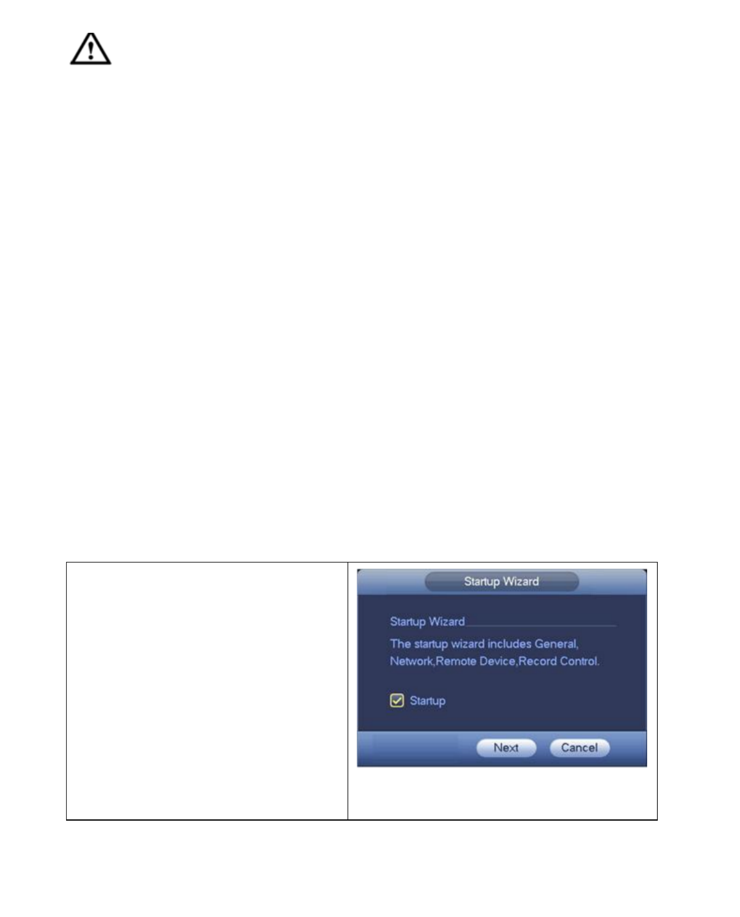
4.2 Startup Wizard
After device successfully booted up, it
goes to startup wizard. See Figure 4- 1.
Click Cancel/Next button, you can see
system goes to login interface.
Tip:
Check the box Startup button here,
system goes to startup wizard again
when it boots up the next time.
Cancel the Startup button, system goes
to the login interface directly when it
boots up the next time.
Figure 4-1

16
: admin. : admin. (administrator, local and network) Username Password
: 888888. : 888888. (administrator, local only) Username Password
: default. Username Password: default (hidden user). Hidden user ―default‖ is for system
interior use only and can not be deleted. When there is no login user, hidden user
―default‖ automatically login. You can set some rights such as monitor for this user so
that you can view some channel view without login.
Figure 4-2
Note: For security reason, modify password after you first login.
Within 30 minutes, three times login failure will result in system alarm and five times login
failure will result in account lock! For General interface settings of the setup wizard see
Figure 4-3.
Figure 4-3
Click Next button, you can go to network interface. See Figure 4-4.
For detailed information, refer to chapter 4- . 11

17
Figure 4-4
Click Next button, you can go to remote device interface. See Figure 4-5.
For detailed information, refer to chapter 0.
Figure 4-5
Click Next button, you can go to Schedule interface. See gure 4-6. Fi
For detailed information, refer to chapter 4.7.2.

18
Figure 4-6
Click Finish button, system pops up a dialogue box. Click the OK button, the startup wizard
is complete. See Figure 4-7.
Figure 4-7
4.3 Navigation Bar
You need to go to the Main menu->Setting->System->General to enable navigation bar
function; otherwise you can not see the following interface. The navigation bar is shown
as below. See Figure 4-8.
Figure 4-8

19
Click button to go to the main menu interface.
4.3.2 Dual-screen operation
Important
This nction is for some series only. fu
Click to select screen 2, you can view an interface shown as below. See Figure 4-9. It
is a navigation bar for screen 2.
Figure 4-9
Click any screen split mode; HDMI screen can display corresponding screens. Now you can
control two screens. See Figure 4- . 10
Figure 4- 10
Note
Screen 2 funciton is null if tour is in process. Disable tour funciton first,
Right now, the screen 2 operation can only be realized on the navigation bard. The
operations on the right-click menu are for screen 1 only.
4.3.3 Output Screen
Select corresponding window-split mode and output channels.
4.3.4 Tour
Click button to enable tour, the icon becomes , you can see the tour is in process.
4.3.5 PTZ
Click , system goes to the PTZ control interface. Refer to chapter 4.6.
4.3.6 Color
Click button , system goes to the color interface. Refer to chapter 4.5.4.1.1.
Make sure system is in one-channel mode.
4.3.7 Search
Click button , system goes to search interface. Refer to chapter 4.8.2.
20
Click button , system goes to alarm status interface. It is to view device status and
channel status. Refer to chapter 4.10.
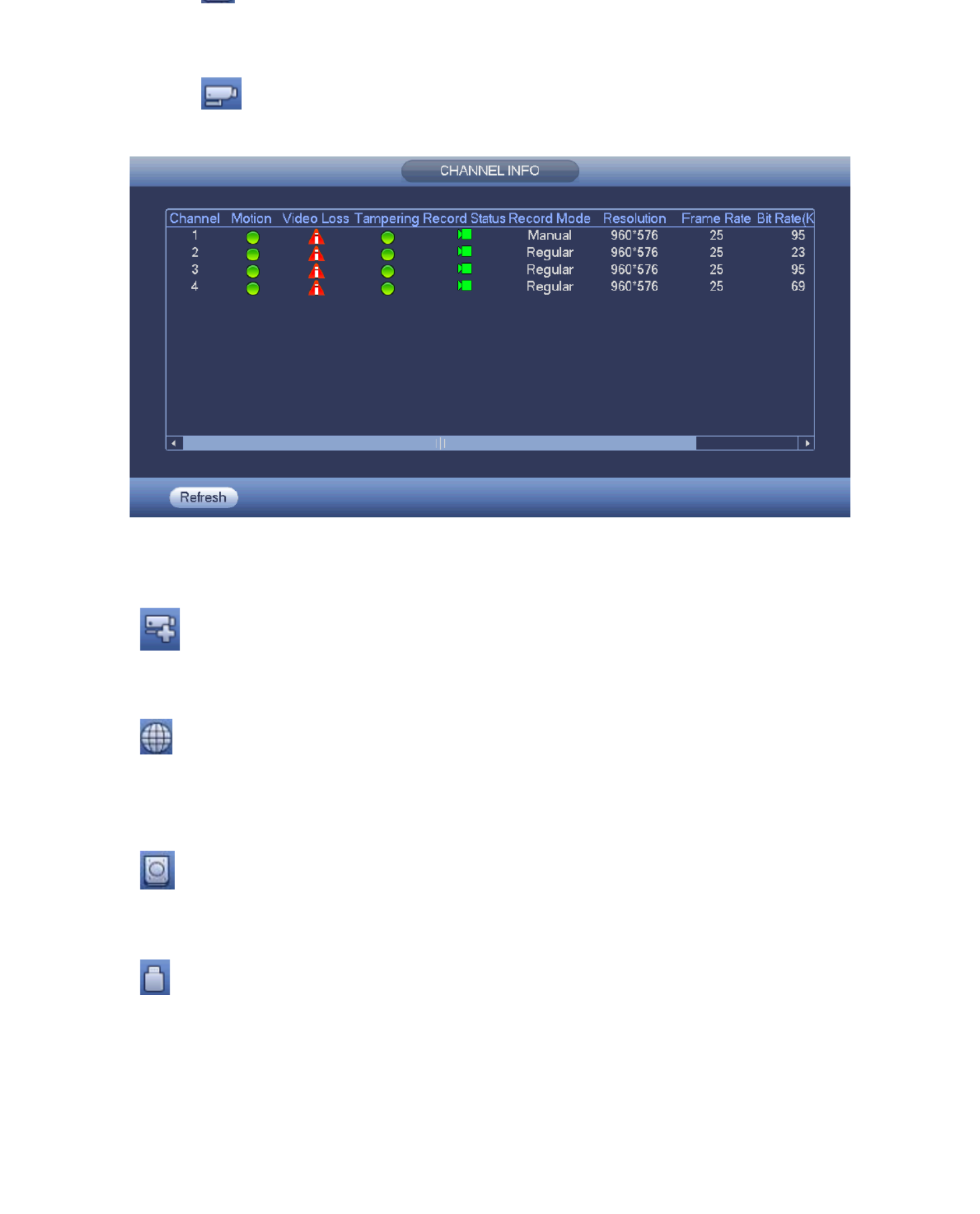
4.3.9 Channel Info
Click button , system goes to the channel information setup interface. It is to view
information of the corresponding channel. See Figure 4- . 11
Figure 4- 11
4.3.10 Remote Device
Click , system goes to the remote device interface. Refer to chapter 0
4.3.11 Network
Click , system goes to the network interface. It is to set network IP address, default
gateway and etc. Refer to chapter 4.11.
4.3.12 HDD Manager
Click system goes to the HDD manager interface. It is to view and manage HDD ,
information. Refer to chapte 4.3.12.
4.3.13 USB Manager
Click system goes to the USB Manager interface. It is to view USB information, backup ,
and update. Refer to chapter 4.3.13 USB Manager and chapter 4.9 Backup .

21
Figure 4- 12
Figure 4- 20
4.4.2 Short-Cut Menu
In the preview interface, for the channel of no -CAM connectioIP n, you can click the icon ―+‖
in the centre of the interface to quickly go to the Remote Device interface. See Figure 4- . 21
Figure 4- 21
From Main menu-> Setting->
Remote device or right click
mouse on the preview
interface and then select
remote device item, you can
see the following interface.
See
Figure 4- . 12
Click Device search button, you can
view the searched IP addresses at the
top pane of the interface. Double click an
IP address or check one IP address and
then click Add button, you can add
current device to the bottom pane of the
interface. System supports add batch
function.
Click Manual Add button, you can add a
device directly. Here you can set
TCP/UPD/auto connection mode. The
default setup is TCP. See Figure 4-20.

22
below. See Figure 4- . 22
: Select a channel from the dropdown list. Channel
: It is to adjust monitor window saturation. The value ranges from 0 to 100. Saturation
The default value is 50. The larger the number, the strong the color is. This value has no
effect on the general brightness of the whole video. The video color may become too
strong if the value is too high. For the grey part of the video, the distortion may occur if
the white balance is not accurate. Note the video may not be attractive if the value is too
low. The recommended value ranges from 40 to 60.
: It is to adjust monitor window bright. The value ranges from 0 to 100. The Brightness
default value is 50. The larger the number is, the bright the video is. When you input the
value here, the bright section and the dark section of the video will be adjusted
accordingly. You can use this function when the whole video is too dark or too bright.
Note the video may become hazy if the value is too high. The recommended value
ranges from 40 to 60.
: It is to adjust monitor window contrast. The value ranges from 0 to 100. The Contrast
default value is 50. The larger the number is, the higher the contrast is. You can use this
function when the whole video bright is OK but the contrast is not proper. Note the video
may become hazy if the value is too low. If this value is too high, the dark section may
lack brightness while the bright section may over exposure .The recommended value
ranges from 40 to 60.
Auto Iris: It is for the device of the auto lens. You can check the box before ON to enable
this function. The auto iris may change if the light becomes different. When you disable
this function, the iris is at the max. System does not add the auto iris function in the
exposure control. This function is on by default.
: It is to switch video up and bottom limit. This function is disabled by default. Mirror
: It is to switch video left and right limit. This function is disabled by default. Flip
:It includes several options: BLC/WDR/HLC/OFF. BLC
BLC: The device auto exposures according to the environments situation so that the
darkest area of the video is cleared
: For the WDR scene, this function can lower the high bright section and enhance WDR
the brightness of the low bright section. So that you can view these two sections clearly
at the same time. The value ranges from 1 to 100. When you switch the camera from
no-WDR mode to the WDR mode, system may lose several seconds record video.
: After you enabled HLC function, the device can lower the brightness of the HLC
brightest section according to the HLC control level. It can reduce the area of the halo
and lower the brightness of the whole video.
: It is to disable the BLC function. Note this function is disabled by default. OFF
: It is to set the white balance mode. It has effect on the general hue of the video. Profile
This function is on by default. You can select the different scene mode such as auto,
sunny, cloudy, home, office, night, disable and etc to adjust the video to the best quality.

23
: The threshold of the white balance is in the sunny mode. Sunny
: The threshold of the white balance is in the night mode. Night
: You can set the gain of the red/blue channel. The value reneges from 0 to Customized
100.
. It is to set device color and the B/W mode switch. The default setup is auto. Day/night
: Device outputs the color video. Color
Auto: Device auto select to output the color or the B/W video according to the device
feature (The general bright of the video or there is IR light or not.)
: The device outputs the black and white video. B/W
: It is to set when there is peripheral connected IR light. Sensor
Figure 4- 22
4.4.4 Channel Name
From main menu->Setting->Remote-Modify, here you can modify the Channel name, you
can see an interface shown as in Figure 4- It is to modify channel name. It max supports 23.
31-character. Note you can only modify the channel name of the connected network camera.
Figure 4- 23

24
4.5.1 Preview
If you want to change system date and time, you can refer to (Main general settings
Menu->Setting->System->General). If you want to modify the channel name, refer to the
display settings (Main Menu->Camera->CAM name)
Refer to the following sheet for detailed information.
Tip:
Preview drag: If you want to change position of channel 1 and channel 2 when you
are previewing, you can left click mouse in the channel 1 and then drag to channel 2,
release mouse you can switch channel 1 and channel 2 positions.
Use mouse middle button to control window split: You can use mouse middle button
to switch window split amount.
4.5.2 Preview control interface
Move you mouse to the top centre of the video of current channel, you can see system
pops up the preview control interface. See Figure 4- . If your mouse stays in this area 25
for more than 6 seconds and has no operation, the control bar automatically hides.
Figure 4- Digital Channel 25
1) Realtime playback
It is to playback the previous 5-60 minutes record of current channel.
Go to the Main menu->Setting->System->General to set real-time playback time. System
may pop up a dialogue box if there is no such record in current channe l.
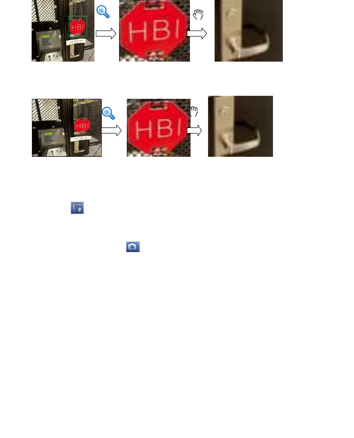
2) It is to zoom in specified zone of current channel. It supports zoom in Digital zoom:
function of multiple-channel.
Click button , the button is shown as .
1
Recording status
3
Video loss
2
Motion detection
4
Camera lock
After device booted up, the system is in
multiple-channel display mode. See Figure
4- . Note the displayed window amount may 24
vary. The following figure is for reference only.
Refer to chapter 1.3 Specifications for the
window-amount your product supported.
Figure 4- 24
25
Figure 4-26
Put the middle button at the centre of the zone you want to zoom in, and move the
mouse, you can view an interface shown as in Figure 4-27.
Figure 4-27
Right click mouse to cancel zoom and go back to the original interface.
3) Manual record function It is to backup the video of current channel to the USB device. :
System can not backup the video of multiple-channel at the same time.
Click button , system begins recording. Click it again, system stops recoridng. You can
find the record file on the flash disk.
4) Manual Snapshot Click to snapshot 1-5 times. The snapshot file is saved on the :
USB device or HDD. You can go to the Search interface (chapter 4.8.2) to view.
4.5.3 Right Click Menu
After you logged in the device, right click mouse, you can see the short cut menu. See
Figure 4- . 28
Window split mode: You can select window amount and then select channels.
PTZ: Click it to go to PTZ interface.
Auto focus: It is to set auto focus function. Make sure the connected network camera
supports this function.
Color setting: Set video corresponding information.
Search: Click it to go to Search interface to search and playback a record file.
Record control: Enable/disable record channel.
Alarm output: It is to set alarm output mode.
Remote device: Search and add a remote device.

26
Tip: Right click mouse to go back to the previous interface.
Figure 4-28
4.5.4 Preview Display Effect Setup
4.5.4.1.1 Video Color
Here you can set hue, brightness, contrast, saturation, gain, white level, color mode and
etc. See Figure 4- . 29
Figure 4- 29
Refer to the following sheet for detailed information.
Item
Note
Period
There are two periods in one day. You can set different
sharpness, brightness, and contrast setup for different
periods.
Effective Time
Check the box here to enable this function and then set
period time.
Sharpness
The value here is to adjust the edge of the video. The
value ranges from 0 to 100. The larger the value is, the
clear the edge is and vice versa. Note there is noise if
the value here is too high. The default value is 50 and
the recommended value ranges from 40 to 60.
Brightness
It is to adjust monitor window bright. The value ranges
from 0 to 100. The default value is 50.
The larger the number, the bright the video is. When
you input the value here, the bright section and the dark
section of the video will be adjusted accordingly. You
can use this function when the whole video is too dark

27
value is too high. The recommended value ranges from
40 to 60.
Contrast It is to adjust monitor window contrast. The value
ranges from 0 to 100. The default value is 50.
The larger the number, the higher the contrast is. You
can use this function when the whole video bright is OK
but the contrast is not proper. Note the video may
become hazy if the value is too low. If this value is too
high, the dark section may lack brightness while the
bright section may over exposure .The recommended
value ranges from 40 to 60.
Saturation
It is to adjust monitor window saturation. The value
ranges from 0 to 100. The default value is 50.
The larger the number, the strong the color is. This
value has no effect on the general brightness of the
whole video. The video color may become too strong if
the value is too high. For the grey part of the video, the
distortion may occur if the white balance is not
accurate. Note the video may not be attractive if the
value is too low. The recommended value ranges from
40 to 60.
Gain
The gain adjust is to set the gain value. The default
value may vary due to different device models. The
smaller the value, the low the noise. But the brightness
is also too low in the dark environments. It can enhance
the video brightness if the value is high. But the video
noise may become too clear.
Color mode
It includes several modes such as standard, color,
bright, gentle. Select a color mode, the sharpness,
brightness, contrast and etc can automatically switch to
corresponding setup.
4.5.4.1.2 Display
From Main Menu->Setting->System->Display, you can go to the following interface. See
Figure 4- . 30
Here you can set menu and video preview effect. All you operation here does not affect the
record file and playback effect.

28
Figure 4- 30
Now you can set corresponding information.
Resolution: There are five options: 1280×1024 (Default), 1280×720, 1920×1080,
1024×768 and 3840×2160 Note the system needs to reboot to activate current setup. .
Note 3840×2160 is for some series only.
VGA+HDMI2: It is for dual-screen operation. Select from the dropdown list according to
your actual situation. Click Apply button, system needs to restart to activate new setup.
For example, 4+4 means for VGA, system max supports 4-window split and for HDMI2,
system max supports 4-window split.
Transparency: Here is for you to adjust transparency. The value ranges from 128 to 255.
Channel name: Here is for you to modify channel name. System max support 25-digit
(The value may vary due to different series). Note all your modification here only applies
to TX- local end. You need to open web or client end to refresh channel name. 64
Time display: You can select to display time or not when system is playback.
Channel display: You can select to channel name or not when system is playback.
Image enhance: Check the box; you can optimize the margin of the preview video.
Original scale: Check the box here to restore video original scale.
Click OK button to save current setup.
4.5.5 Preview Parameters Tour
Set preview display mode, channel display sequence and tour setup.
Set preview display mode: On the preview interface, right click mouse, you can view
right-click menu. Now you can select preview window amount and channel.
Set channel display mode: On the preview interface, if you want to change channel 1
and channel 4 position, right click channel 1 video window and then drag to the channel
4 video window, release button, you can change channel 1 and channel 4 position.
Tour setup: Here you can set preview window channel display mode and interval. Follow
the steps listed below.
From Main menu->Setting->System->Display->Tour, you can see an interface shown as in

29
Enable tour: Check the box here to enable tour function.The general tour supports all
types of window split mode.
Interval: Input proper interval value here. The value ranges from 1-120 seconds.
Motion tour type: System support 1/4-window tour. Note you need to go to the main
menu->Setting->Event->Video detect->Motion detect to enable tour function .
Alarm tour type: System support 1/4-window tour. Note you need to go to the main
menu->Setting->Event->Alarm to enable tour function .
Window split:It is to set window split mode.
Figure 4-31
Tip: On the navigation bar, click / to enable/disable tour. Click save button to save
current setup.
4.6 PTZ
Note: Before you control the PTZ, make sure the PTZ camera and the - network TX 64
connection is OK and the corresponding settings are right.
4.6.1 PTZ Control
After completing all the setting click save button. Right click mouse (click ―Fn‖ key in the
remote control). The interface is shown as in Figure 4-32. Note you can only go to the
PTZ control interface when you are in 1-window display mode.
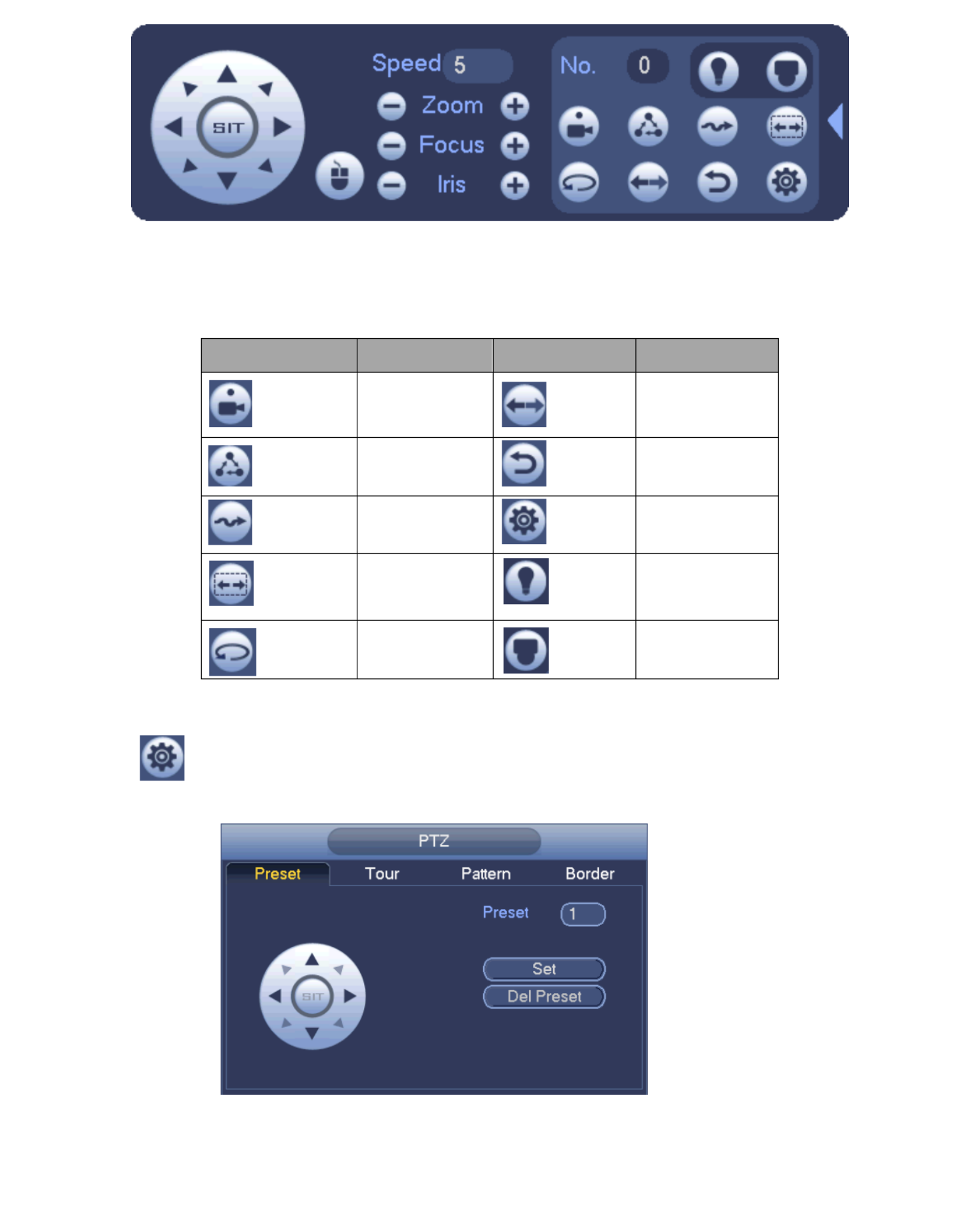
Figure 4-32

30
The PTZ operation is only valid in one-window mode.
Here you can control PTZ direction, speed, zoom, focus, iris, preset, tour, scan, pattern aux
function, light and wiper, rotation and etc.
Speed is to control PTZ movement speed. The value ranges from 1 to 8.The speed 8 is
faster than speed 1. You can use the remote control to click the small keyboard to set.
You can click of the zoom, focus and iris to zoom in/out, definition and and
brightness.
The PTZ rotation supports 8 directions. If you are using direction buttons on the front panel,
there are only four directions: up/down/left/right.
Figure 4-33
In the middle of the eight direction arrows, there is a 3D intelligent positioning key. See
Figure 4-34 Make sure your protocol supports this function and you need to use mouse to .
control.
Click this key, system goes back to the single screen mode. Drag the mouse in the screen to
adjust section size. The dragged zone supports 4X to 16X speeds. It can realize PTZ
automatically. The smaller zone you dragged, the higher the speed.
Figure 4- 34
Name
Function
key
function
Shortcut
key
Function
key
function
Shortcut
key
Zoom
Near
Far
Focus
Near
│
Far
►│
Iris
close
Open
31
See Figure 4-35.
Figure 4-35
Refer to the following sheet for detailed information. Note the above interface may vary
due to different protocols. The button is grey and can not be selected once the current
function is null.
Icon
Function
Icon
Function
Preset
Flip
Tour
Reset
Pattern
Aux
Scan
Aux on-off
button
Rotate
Go to menu
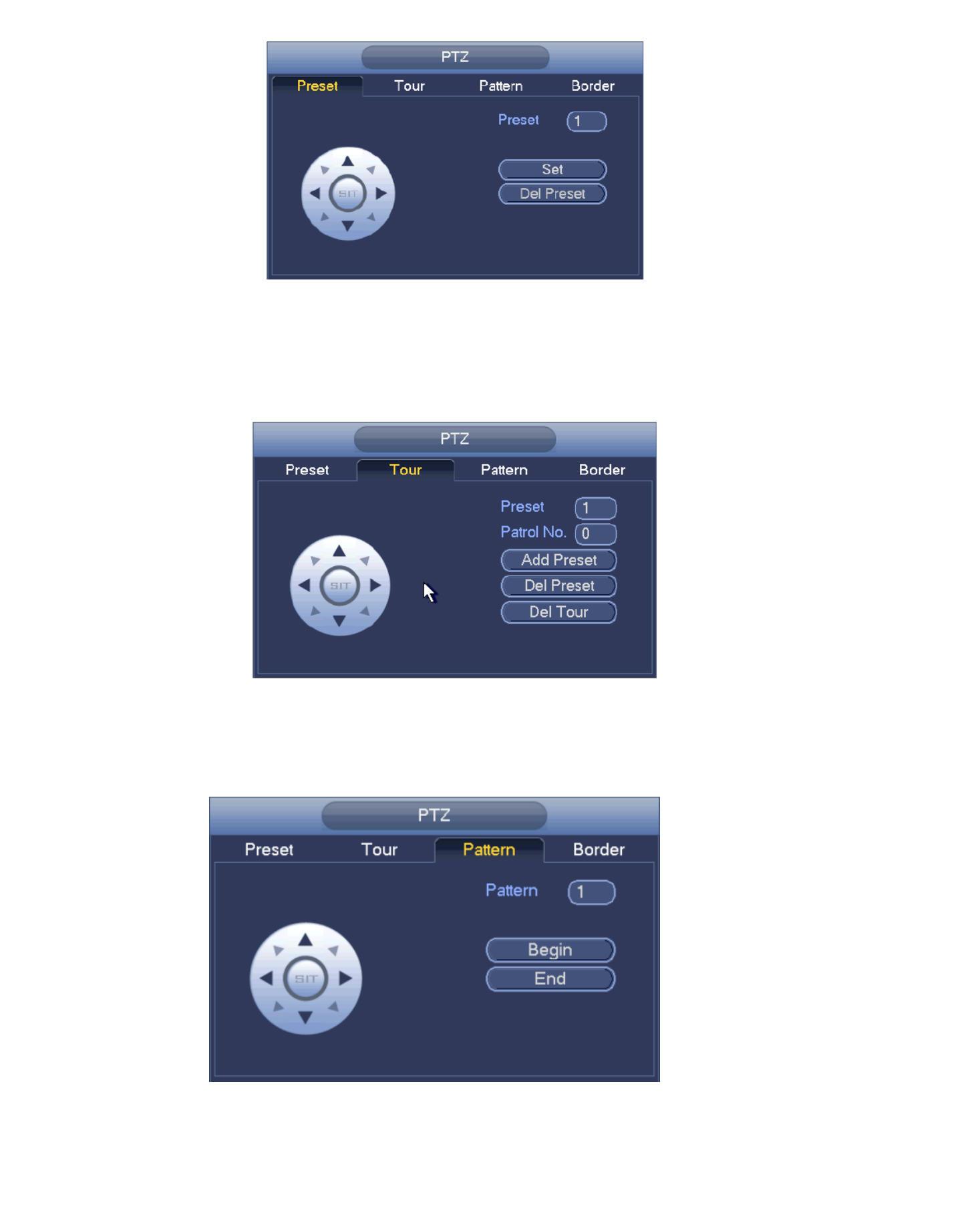
4.6.1.1 PTZ Function Setup
Click , you can go to the following interface to set preset, tour, pattern, and scan. See
Figure 4-36.
Figure 4-36
32
proper position. The interface is shown as in Figure 4-37. Click Set button and then input
preset number. Click Set button to save current preset.
Figure 4- 37
Tour Setup
In Figure 4-36, click tour button. Input tour value and preset No. Click Add preset button to
add current preset to the tour. See Figure 4- . 38
Tip:: Repeat the above steps to add more presets to the tour. Click Del preset button to
remove it from the tour. Note some protocols do not support delete preset function.
Figure 4- 38
Pattern Setup
In Figure 4-36, click Pattern button and input pattern number. Click Begin button to start
direction operation. Or you can go back to Figure 4- to operate zoom/focus/iris/direction 39
operation.
Figure 4- 39
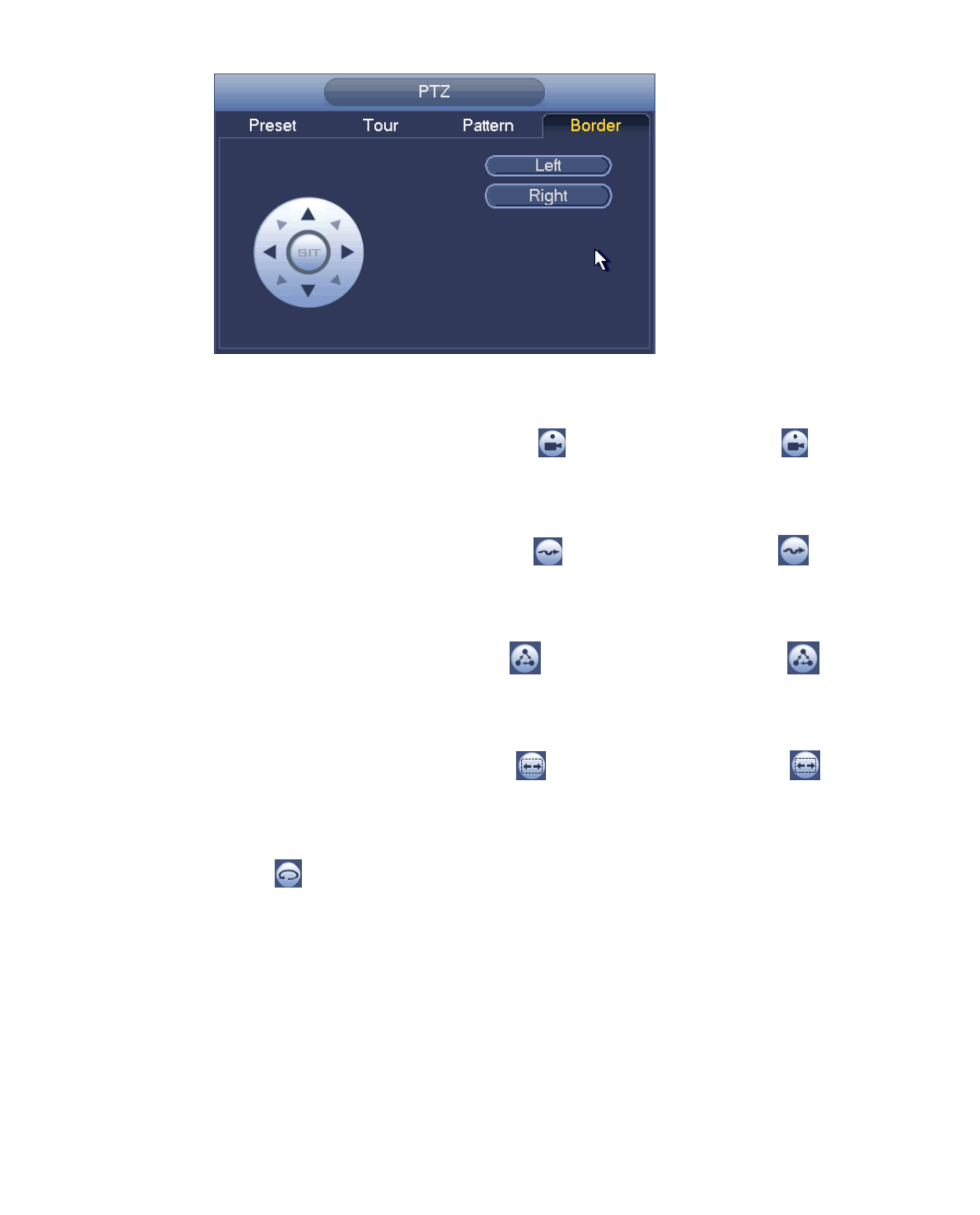
33
click Left button.
Use direction buttons to set camera right limit and then click Right button. Now the border
setup process is complete. See Figure 4-40.
Figure 4-40
4.6.1.2 Call PTZ Function
Call Preset
In Figure 4-36, input preset value and then click to call a preset. Click again to
stop call.
Call Pattern
In Figure 4-36, input pattern value and then click to call a pattern. Click again to
stop call.
Call Tour:
In Figure 4-36, input tour value and then click to call a tour. Click again to stop
call.
Call Scan:
In Figure 4-36, input Scan value and then click to call a tour. Click again to stop
call.
Rotate:
In Figure 4-36, click to enable the camera to rotate.
System supports preset, tour, pattern, scan, rotate, light and etc function.
Note:
Preset, tour and pattern all need the value to be the control parameters. You can
define it as you require.
You need to refer to your camera user’s manual for Aux definition. In some cases, it
can be used for special process.
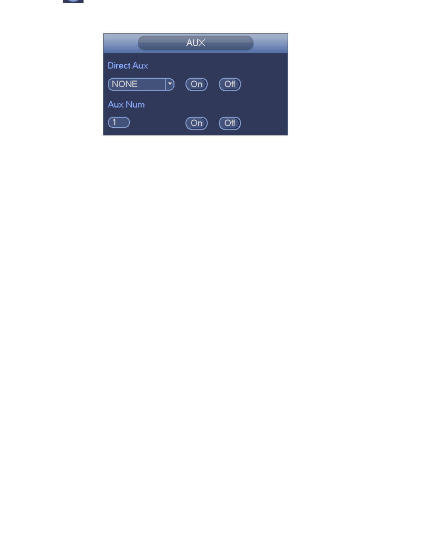
34
Click , system goes to the following interface. The options here are defined by the
protocol. The aux number is corresponding to the aux on-off button of the decoder. See
Figure 4-41.
Figure 4-41
4.7 Record and Snapshot
The record/snapshot priority is: Alarm->Motion detect->Schedule.
4.7.1 Encode
4.7.1.1 Encode
Encode setting is to set -CAM encode mode, resolution, bit stream type and etc IP
From Main menu->Setting->System->Encode, you can see the following interface. See
Figure 4-42 and Figure 4- 45.
Channel: Select the channel you want.
Type: Select from the dropdown list. There are three options: regular/motion
detect/alarm. You can set the various encode parameters for different record types.
Compression: System supports H.264, MPEG4, MJPEG and etc.
Resolution: The mainstream resolution type is -CAMIP ’s encoding config. Generally
there is D1/720P/1080P. The main stream supports 2048 1536 , 1080× (3M)1920×
( ) × ( × ) × ( ) × ( )1080P , 1280 1024 S GA , 1280 960 1.3M ,1280 720 720P ,704
× ( )576 D1 and the sub stream supports 704 576 ,352 288 CIF . × (D1) × ( )
Frame rate: It ranges from 1f/s to 25f/s in NTSC mode and 1f/s to 30f/s in PAL mode.
t rate type: System supports two types: CBR and VBR. In VBR mode, you can set Bi
video quality.
Quality: There are six levels ranging from 1 to 6. The sixth level has the highest image
quality.
Video/audio: You can enable or disable the video/audio. Note, once you enable audio
function for one channel, system may enable audio function of the rest channels by
default.
Copy After you complete the setup, you can click Copy button to copy current set:up
to other channel(s). You can see current channel number is grey. Check the number
to select the channel or you can check the box ALL. Click the OK button to complete
the setup. Note, once you check the All box, you set same encode setup for all
channels. Audio/video enable box, overlay button and the copy button is shield.

35
Figure 4- 42
4.7.1.2 Overlay
Click overlay button, you can see an interface is shown in Figure 4-43 and Figure 4- . 45
Cover area: Here is for you to cover area section. You can drag you mouse to set
proper section size. In one channel video, system max supports 4 zones in one
channel.
Preview/monitor: The cover area has two types. Preview and Monitor. Preview means
the privacy mask zone can not be viewed by user when system is in preview status.
Monitor means the privacy mask zone can not be view by the user when system is in
monitor status.
Time display: You can select system displays time or not when you playback. Click
set button and then drag the title to the corresponding position in the screen.
Channel display: You can select system displays channel number or not when you
playback. Click set button and then drag the title to the corresponding position in the
screen.
Figure 4-43

36
Snapshot mode: There are two modes: regular and trigger. If you set regular mode,
you need to set snapshot frequency. If you set trigger snapshot, you need to set
snapshot activation operation.
Image size: Here you can set snapshot picture size.
Image quality: Here you can set snapshot quality. The value ranges from 1 to 6.
Interval: It is for you to set timing (schedule) snapshot interval.
Figure 4-44
Figure 4-45
4.7.2 Schedule
The record type priority is: Alarm>Motion detect>Regular.
4.7.2.1 Schedule Record
Set record time, record plan and etc. Note system is in 24-hour record by default after its
first boot up.
In the main menu, from Main menu->Setting->Storage->Schedule, you can go to
schedule menu. See Figure 4- There are total six periods. 50.
Channel: Select the channel number first. You can select ―all‖ if you want to set for the
whole channels.
: Sync connection icon. Select icon of several dates, all checked items can be
edited or together. Now the icon is shown as .
: Click it to delete a record type from one period.
Record Type: Check the box to select corresponding record type. There are four types:
Regular/MD (motion detect)/Alarm/MD&Alarm.

37
Menu->Setting->System->General) to add holiday first. Otherwise you can not see
this item.
Pre-record: System can pre-record the video before the event occurs into the file. The
value ranges from 1 to 30 seconds depending on the bit stream.
Redundancy: System supports redundancy backup function. It allows you backup
recorded file in two disks. You can highlight Redundancy button to activate this
function. Note, before enable this function, set at least one HDD as redundant. (Main
menu->Setting->Storage->HDD Manager). Note this function is null if there is only
one HDD.
ANR: It is to save video to the SD card of the network camera in case the network
connection fails. The value ranges from 0s 43200s. After the network connection ~
resumed, the system can get the video from the SD card and there is no risk of record
loss.
Period setup: Click button after one date or a holiday, you can see an interface
shown as in Figure 4- .There are four record types: regular, motion detection (MD), 52
Alarm, MD & alarm.
Following the steps listed below to draw the period manually.
a) Select a channel you want to set. See Figure 4-46.
Figure 4- 46
b) 47 Set record type. See Figure 4-
Figure 4-47
c) Draw manually to set record period. There are six periods in one day. See Figure
4- . 48
Figure 4- 48

38
click save button, system goes back to the previous menu. There are color bars for your
reference. Green color stands for regular recording, yellow color stands for motion
detection and red color stands for alarm recording. The white means the MD and alarm
record is valid. Once you have set to record when the MD and alarm occurs, system will
not record neither motion detect occurs nor the alarm occurs.
Figure 4- 49
Figure 4-50
Quick Setup
Copy function allows you to copy one channel setup to another. After setting in channel 1,
click Copy button, you can go to interface Figure 4-51. You can see current channel name is
grey such as channel 1. Now you can select the channel you wan to paste such as channel
3/4. If you wan to save current setup of channel 1 to all channels, you can click the first box
―ALL‖. Click the OK button to save current copy setup. Click the OK button in the Encode
interface, the copy function succeeded.
39
Figure 4-51
Click OK button to save current setup.
4.7.2.2 Schedule Snapshot
From Main menu->Setting->Storage->Record or on the preview interface, right click mouse
and then select record item, you can see Figure 4-52.
Select snapshot channel and enable snapshot function. Click save button.
Figure 4-52
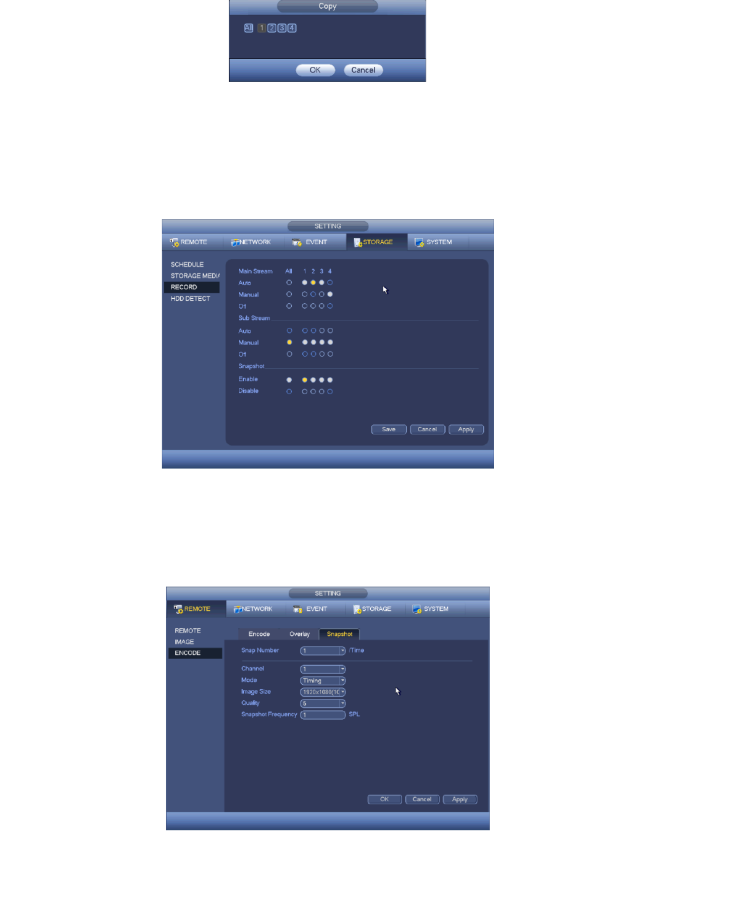
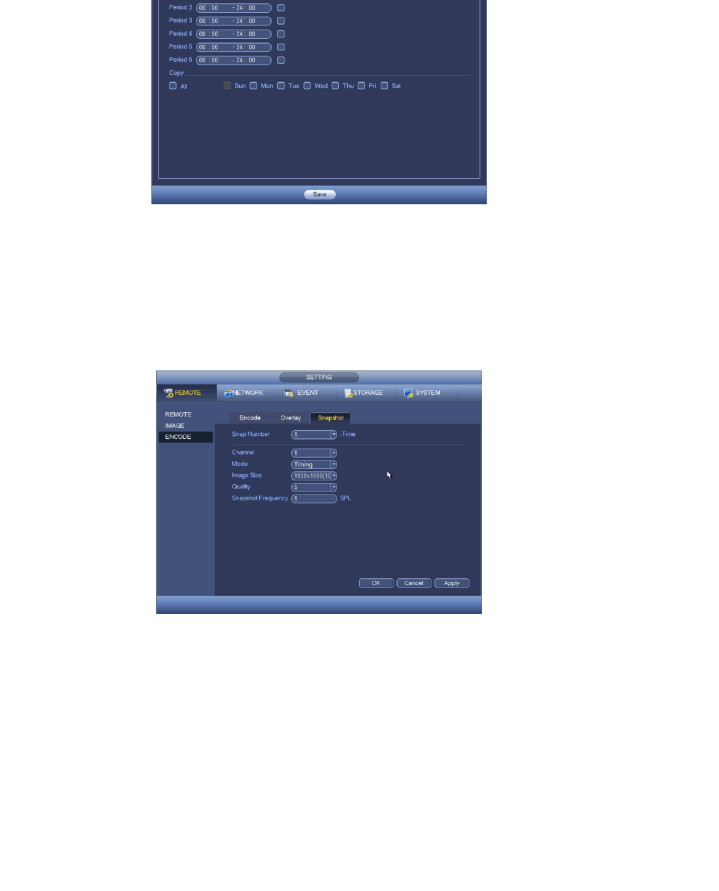
From Main menu->Setting->Camera->Encode->Snapshot, you can go to snapshot interface.
See Figure 4-53.
Select the snapshot channel from the dropdown list and then select snapshot mode as
Timing (Schedule) from the dropdown list and then set picture size, quality and snapshot
frequency.
Figure 4- 53

40
periods in one day. The setup steps are general the same.
Figure 4-54
Note
Note the trigger snapshot has the higher priority than regular snapshot. If you have
enabled these two types at the same time, system can activate the trigger snapshot
when alarm occurs, and otherwise system just operates the regular snapshot. an
Only the trigger snapshot supports this function. Th regular snapshot function can not e
send out picture via the email. But you can upload the picture to a FTP.
4.7.3 Motion detect record/snapshot
4.7.3.1 Motion detect record
a) From Main menu->Setting->Event->Detect, you can go to the following interface.
See Figure 4-55.
Figure 4-55
b) Select motion detect from the event type dropdown list. Select a channel from the
dropdown list and then check the enable button to enable motion detect function.
Here you can set motion detection regions. There are four regions for you to set (red,
yellow, blue and green). Select one of the colored regions first. Then click the left

41
In the test area the best setting for sensitivity and threshold is 60 and 10 respectively.
Depending on your given environment this settings can be vary. Sensitivity and
threshold can be set in the range from 0 to 100. The higher the sensitivity and the
lower the threshold are set the more motion is detected. For example: When a leaf
falls or a cat is running in the selected area a motion will be detected.
In this case a subjective setting by the customer is requested!
After you completed the setup remember to click the save button to save current
setup. If you click the right button of the mouse to exit the region setup interface
system will not save your zone setup.
c) Period: Click set button, you can see an interface is shown as in Figure 4-57. Here
you can set motion detect period. System only enables motion detect operation in
the specified periods. It is not for video loss or the tampering. There are two ways for
you to set periods. Note system only supports 6 periods in one day. See Figure 4-57.
In Figure 4-56, Select icon of several dates, all checked items can be edited
together. Now the icon is shown as . Click to delete a record type from one
period.
In Figure 4- . Click button after one date or a holiday56 . There are four record types:
regular, motion detection (MD), Alarm, MD & alarm.
d) Set sensitivity. Note the six level has the highest sensitivity. th
e) Click Save button to complete motion detect setup.
f) From Main menu->Setting->Storage->-Schedule. See Figure 4-56
g) Set motion detect record channel, period and the record type shall be motion detect
(MD).
h) Click Copy button to copy current setup to other channel(s).
i) Click OK button to complete motion detect record setup.
Figure 4-56
42
Figure 4- 57
4.7.3.2 Motion Detect Snapshot
a) From Main menu->Setting->Camera->Encode->Snapshot, you can go to snapshot
interface. See Figure 4- . 58
b) 60 In Figure 4- , select trigger snapshot from the dropdown list and then set picture
size, quality and snapshot frequency. Click OK button to save current setup.
c) From Main menu->Setting->Event->Detect, here you can select motion detect type,
motion detect channel and then check the enable box.
d) Click OK button to complete motion detect setup.
Figure 4- 58
4.7.4 Alarm Record/Snapshot
4.7.4.1 Alarm Record
a) Optional: (Alarm setup information, to connect alarm input and alarm output cable
(such as light, siren and etc)).
b) The record priority is: Alarm>Motion detect>Regular.
In the main menu, from Setting->Event-> Alarm, you can see alarm setup interface. See
Figure 4- . 59
Alarm in: Here is for you to select channel number.
Event type: There are four types. Local input/network input/ -CAM external/ -CAM IP IP

43
Network input alarm: It is the alarm signal from the network.
-CAM external alarm: It is the on-off alarm signal from the front-end device and can IP
activate the local TX- 64.
-CAM offline alarm: Once you select this item, system can generate an alarm when IP
the front-end IP-CAM disconnects with the local TX-64. The alarm can activate record,
PTZ, snapshot and etc. The alarm can last until the -CAM and the - IP TX 64
connection resumes.
Enable: You need to highlight this button to enable current function.
Type: normal open or normal close.
c) Click Save button to complete alarm setup interface.
Figure 4- 59
d) From Ma menu->Setting->Storage->Schedule, you can go to Figure 4-54. in
e) Select alarm channel, period and the record type shall be alarm.
f) Click Copy button to copy current setup to other channel(s).
g) Click OK button to save alarm record information.
4.7.4.2 Alarm Snapshot
a) Refer to chapter 4.7 to enable timing snapshot.
b) From Main menu->Setting->Storage->schedule, you can go to Figure 4- to enable 54
snapshot function.
c) From Main menu->Setting->Event->Alarm, you can go to Figure 4- to set alarm 60
parameter and enable snapshot function.
d) Click Save button to save alarm snapshot setup.

44
Figure 4- 60
4.7.5 Manual Record/Snapshot
You need to have proper rights to implement the following operations. Make sure the
HDD has been properly installed.
4.7.5.1 Manual Record
a) Right click mouse and select manual record or in the main menu from ,
Setting->Storage->Manual Record. Manual record menu is shown as in Figure 4-61.
Tip: You can click Rec button on the front panel (if possible) to go to the Manual Record
interface.
Figure 4-61
b) Check the box here to select manual record channel(s). You can see the
corresponding indicator light on the front panel is on.
Channel: It is to display device all channels.
Manual: It has the highest priority. Enable corresponding channel to record no matter
what period applied in the record setup. Now system is record general file.
Auto: System enables auto record function as you set in chapter 4.7.2 schedule
interface (General/Motion detect/Alarm)
Stop: Stop current channel record/Snapshot no matter what period applied in the record
setup.
45
4.7.5.2 Manual Snapshot
Click button at the preview control bar, you can snapshot 1-5 picture(s). From main
menu->Setting->Camera->Encode->Snapshot, you can set snapshot times.
4.7.6 Holiday Record/Snapshot
It is for you to set holiday record or snapshot plan. Note the holiday record/snapshot setup
has the higher priority than the ordinary date record/snapshot setup.
4.7.6.1 Holiday Record
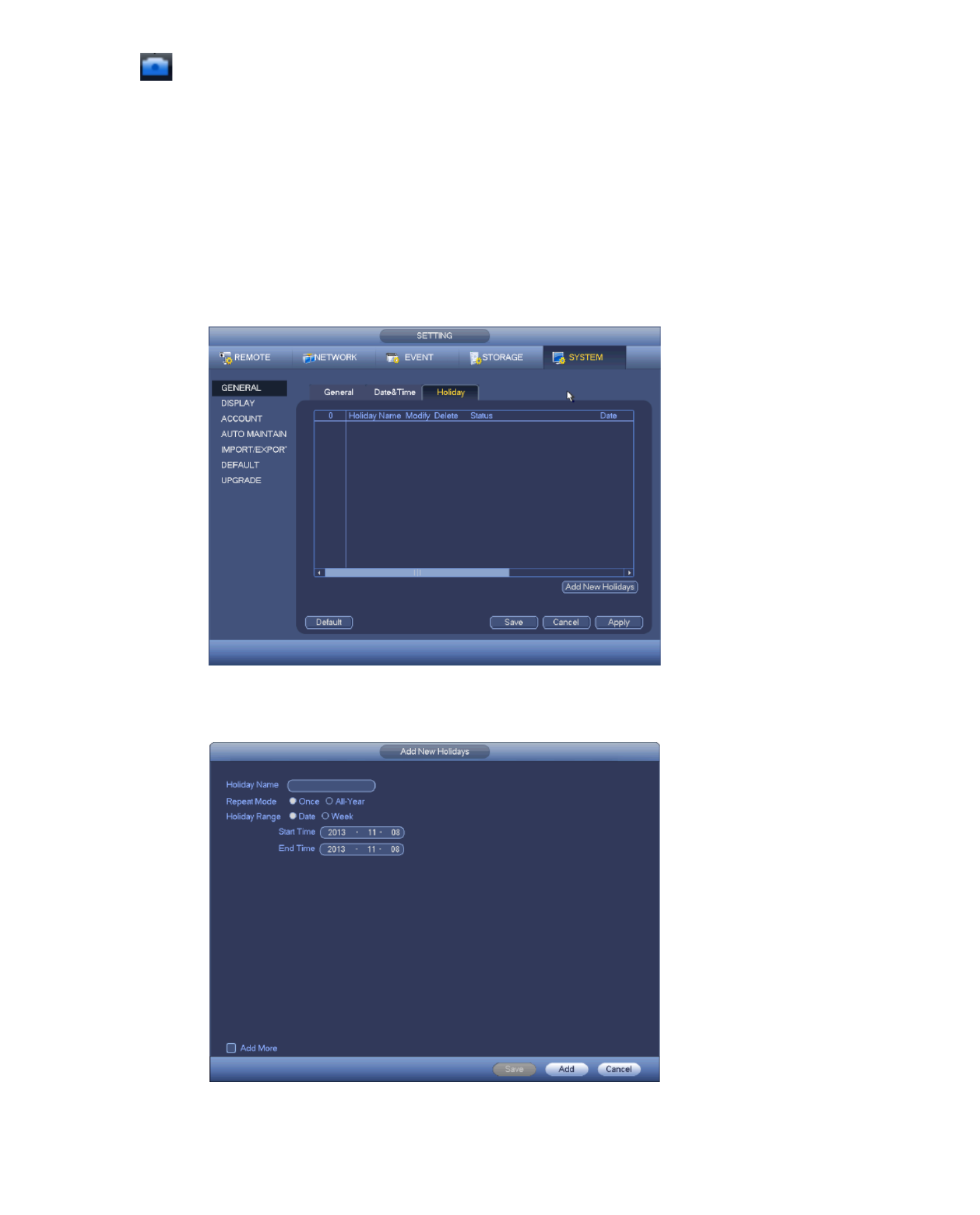
a) From Mani menu->Setting->System->General, you can go to the following interface.
See Figure 4-62.
Figure 4- 62
b) Click Add new holiday button, you can see an interface shown as in Figure 4-63.
Here you can set holiday date name, repeat mode, start time/end time and etc.
Figure 4- 63

46
d) From Main menu->setting->Storage->schedule, you can go to schedule interface.
See Figure 4-64. Now you can set period and record type of holiday time. Refer to
chapter 4.7.6 for detailed setup information.
Figure 4-64
e) Click OK button to set holiday record setup.
4.7.6.2 Holiday Snapshot
Set Holiday date first. Refer to step a) to step c) of chapter4.7.6.1.
From Main menu->Setting->Storage->Schedule, you can go to schedule interface. See
Figure 4-64 Click Holiday item to set snapshot period . .
Set holiday snapshot type (Trigger/Regular).
4.7.7 Other Record/Snapshot
Motion detects & Alarm record or snapshot, refer to chapter 4.7.
Video loss or tampering record or snapshot function, refer to chapter 4.7.3.
4.8 Playback and Search
4.8.1 Real-time Playback
Refer to chapter 4.5.2 for real-time playback information.
4.8.2 Search Interface
From Main menu->Search, or on the preview interface right click mouse and then select
search item, you can go to the following interface. See Figure 4-65.

47
Figure 4-65
Refer to the following sheet for more information.
SN
Name
Function
1
Display
window
Here is to display the searched picture or file.
Support 1/4-window playback.
2
Search
type
Here you can select to search the picture or the recorded file.
You can select to play from the read-write HDD, from
peripheral device or from redundancy HDD.
Before you select to play from the peripheral device, connect
the corresponding peripheral device. You can view all record
files of the root directory of the peripheral device. Click the
Browse button; you can select the file you want to play.
Important
Redundancy HDD does not support picture backup
function, but it supports picture playback function. You can
select to play from redundancy HDD if there are pictures on
the redundancy HDD.
3
Calendar
The blue highlighted date means there is picture or file.
Otherwise, there is no picture or file.
In any play mode, click the date you want to see, you can see
the corresponding record file trace in the time bar.
4
Playback
Playback mode 1/4. (It may vary due to different series.) :

48
selection
pane.
In 4-window playback mode: you can select 4 channels
according to your requirement.
The time bar will change once you modify the playback mode
or the channel option.
5
Card
number
search
The card number search interface is shown as below. Here you
can view card number/field setup bar. You cam implement
advanced search. Current series product supports this
function.
6
Mark file
list button
Click it to go to mark file list interface. You can view all mark
information of current channel by time. Refer to chapter 4.8.2.3
for detailed information.
7
File list
switch
button
Double click it, you can view the picture/record file list of
current day.
The file list is to display the first channel of the record file.
The system can display max 128 files in one time. Use the
│and │ or the mouse to view the file. Select one item, and
then double click the mouse or click the ENTER button to
playback.
You can input the period in the following interface to begin
accurate search.
File type R regular record A external alarm reco:—;—rd;
M Motion detect record. —
Lock file. Click the file you want to lock and click the button
to lock. The file you locked will not be overwritten.
8
Playback
control
pane.
►/
Play/Pause
There are three ways for you to begin playback.
The play button
Double click the valid period of the time bar.
Double click the item in the file list.
In slow play mode, click it to switch between play/pause.
■
Stop
Backward play
In normal play mode, left click the button, the file begins
backward play. Click it again to pause current play.
In backward play mode, click ►/ to restore normal play.
│
/
In playback mode, click it to play the next or the previous
section. You can click continuously when you are watching
the files from the same channel.
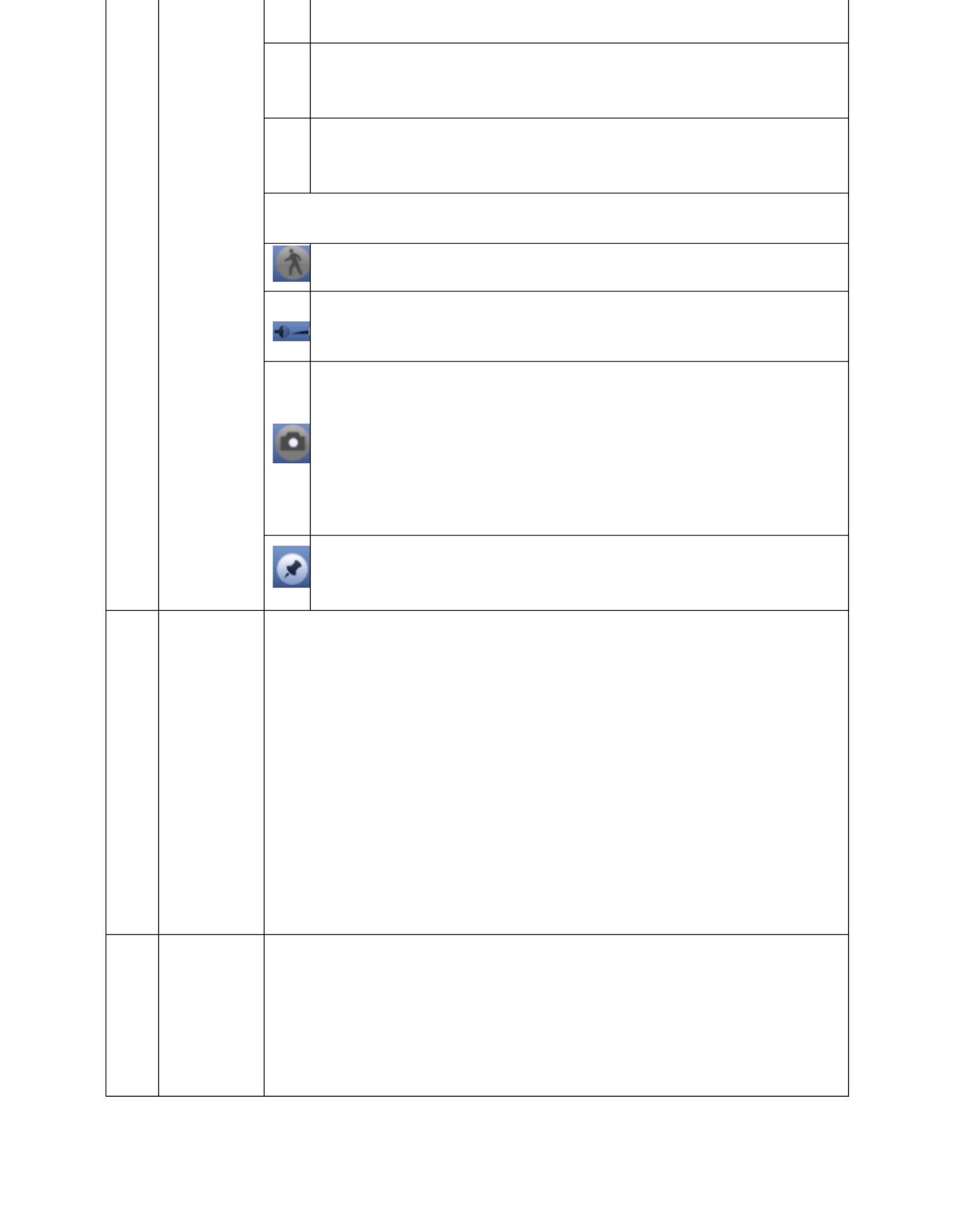
49
In frame by frame playback mode, click ►/ to restore
normal playback.
► Slow play
In playback mode, click it to realize various slow play
modes such as slow play 1, slow play 2, and etc.
Fast forward
In playback mode, click to realize various fast play modes
such as fast play 1,fast play 2 and etc.
Note: The actual play speed has relationship with the software
version.
Smart search
The volume of the playback
Click the snapshot button in the full-screen mode, the
system can snapshot 1 picture.
System supports custom snap picture saved path. Connect
the peripheral device first, click snap button on the
full-screen mode, you can select or create path. Click Start
button, the snapshot picture can be saved to the specified
path.
Mark button.
Note this function is for some series product only. Make
sure there is a mark button in the playback control panel .
9
Time bar
It is to display the record type and its period in current search
criteria.
In 4-window playback mode, there are corresponding four
time bars. In other playback mode, there is only one time bar.
Use the mouse to click one point of the color zone in the time
bar, system begins playback.
The time bar is beginning with 0 o'clock when you are setting
the configuration. The time bar zooms in the period of the current
playback time when you are playing the file.
The green color stands for the regular record file. The red
color stands for the external alarm record file. The yellow stands
for the motion detect record file.
10
Time bar
unit
●The option includes: 24H, 12H, 1H and 30M. The smaller the
unit, the larger the zoom rate. You can accurately set the time in
the time bar to playback the record.
The time bar is beginning with 0 o'clock when you are setting
the configuration. The time bar zooms in the period of the current
playback time when you are playing the file.

50
11
Backup
can see the backup menu. System supports customized path
setup. After select or create new folder, click the Start button
to begin the backup operation. The record file(s) will be
saved in the specified folder.
Check the file again you can cancel current selection.
System max supports to display files from one channel. 32
After you clip on record file, click Backup button you can save
it.
For one device, if there is a backup in process, you can not
start a new backup operation.
12
Clip
It is to edit the file.
●Play the file you want to edit and then click this button when you
want to edit. You can see the corresponding slide bars in the time
bar of the corresponding channel. You can adjust the slide bar or
input the accurate time to set the file end time.
After you set, you can click Clip button again to edit the
second period. You can see the slide bar restore its previous
position.
Click Backup button after clip, you can save current contents
in a new file.
You can clip for one channel or multiple-channel. The
multiple-channel click operation is similar with the
one-channel operation.
Note:
System max supports 1024 files backup at the same
time.
You can not operate clip operation if there is any file has
been checked in the file list.
13
Record
type
In any play mode, the time bar will change once you modify the
search type.
Other Functions
14
Smart
search
When system is playing, you can select a zone in the
window to begin smart search. Click the motion detect
button to begin play.
Once the motion detect play has begun, click button again
will terminate current motion detect file play.
There is no motion detect zone by default.
If you select to play other file in the file list, system switches
to motion detect play of other file.
During the motion detect play process, you can not
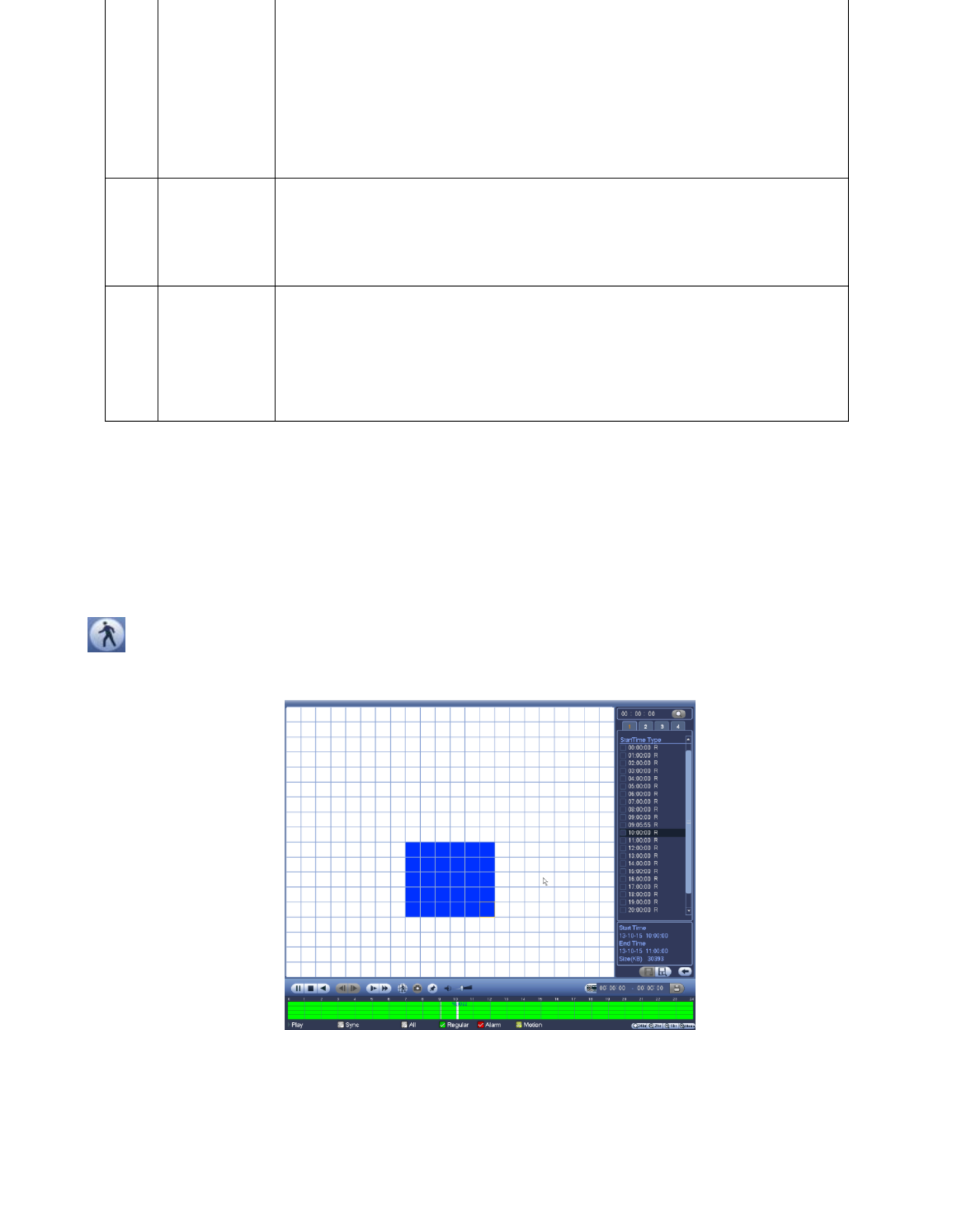
51
15
Other
channel
synchroniz
ation
switch to
play when
playback
When playing the file, click the number button, system can
switch to the same period of the corresponding channel to play.
16
Digital
zoom
When the system is in full-screen playback mode, left click
the mouse in the screen. Drag your mouse in the screen to
select a section and then left click mouse to realize digital
zoom. You can right click mouse to exit.
17
Manually
switch
channel
when
playback
During the file playback process, you can switch to other
channel via the dropdown list or rolling the mouse.
This function is null if there is no record file or system is in
smart search process.
Note: All the operations here (such as playback speed, channel, time and progress) have
relationship with hardware version. - s do not support some functions or playback TX 64
speeds.
4.8.2.1 Smart Search
During the multiple-channel playback mode, double click one channel and then click the
button, system begins smart search. System supports 396(22*18 PAL) and 330(22*15
NTSC) zones. Left click mouse to select smart search zones. See Figure 4-66.
Figure 4-66

52
search playback.
Important
System does not support motion detect zone setup during the full-screen mode.
During the multiple-channel playback, system stops playback of rest channels if
you implement one-channel smart search.
4.8.2.2 Accurate playback by time
Select records from one day, click the list, you can go to the file list interface. You can input
time at the top right corner to search records by time. See image on the left side of the
Figure 4-67. For example, input time 11:00.00 and then click Search button , you can
view all the record files after 11:00.00 (The records includes current time.). See image on the
right side of the Figure 4-67. Double click a file name to playback.
Note
After you searched files, system implement accurate playback once you click Play for
the first time.
System does not support accurate playback for picture.
System supports synchronization playback and non-synchronous playback. The
synchronization playback supports all channels and non-synchronous playback only
supports accurately playback of current select channel.
Figure 4-67
4.8.2.3 Mark Playback
Make sure your purchased device support this function. You can use this function
only if you can see the mark playback icon on the Search interface .
When you are playback record, you can mark the record when there is important information.
After playback, you can use time or the mark key words to search corresponding record and
then play. It is very easy for you to get the important video information.

53
following interface. See Figure 4- . 68
Figure 4- 68
Playback Mark During 1-window playback mode, click mark file list button ,you get :
to mark file list interface. Double click one mark file, you can begin playback from the
mark time.
Play before mark time Here you can set to begin playback from previous N seconds of :
the mark time.
Note
Usually, system can playbacks previous N seconds record if there is such kind of record file.
Otherwise, system playbacks from the previous X seconds when there is such as kind of
record.
Mark Manager Click the mark manager button on the Search interface (Figure :
4-66); you can go to Mark Manager interface. See Figure 4- . System can manage all 69
the record mark information of current channel by default. You can view all mark
information of current channel by time.
Figure 4- 69
Modify Double click one mark information item, you can see system pops up a dialogue :
box for you to change mark information. You can only change mark name here.
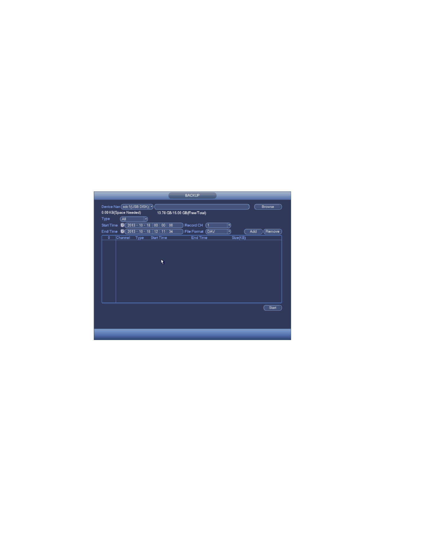
54
Note
After you go to the mark management interface, system needs to pause current
playback. System resume playback after you exit mark management interface.
If the mark file you want to playback has been removed, system begin playbacking from
the first file in the list.
4.8.3 Picture Playback
a) From Main menu->Search, or on the preview interface right click mouse .
b) At the top right pane, you can check the box to select picture and then select
playback interval.
4.9 Backup
4.9.1 File Backup
In this interface, you can backup record file to the USB device.
a) Connect USB burner, USB device or portable HDD and etc to the device.
b) From Main menu->Backup, you can go to the Backup interface. See Figure 4-70.
Figure 4-70
c) Select backup device and then set channel, file start time and end time.
d) Click add button, system begins search. All matched files are listed below. System
automatically calculates the capacity needed and remained. See Figure 4-71.
e) System only backup files with a √ before channel name.
f) Click backup button, you can backup selected files. There is a process bar for you
reference.
g) When the system completes backup, you can see a dialogue box prompting
successful backup.
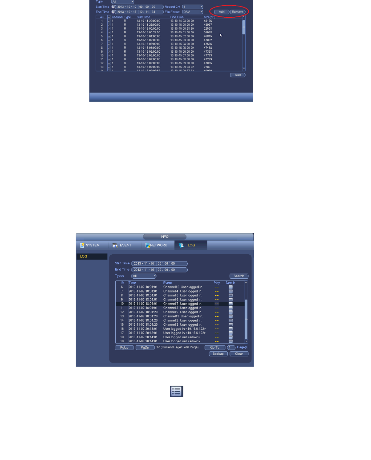
55
Figure 4-71
h) Click backup button, system begins burning. At the same time, the backup button
becomes stop button. You can view the remaining time and process bar at the left
bottom.
Note
During backup process, you can click ESC (right mouse click) to exit current
interface for other operation (For some series product only). The system will not
terminate backup process.
The file name format usually is: Channel number+Record type+Time. In the file
name, the YDM format is Y+M+D+H+M+S. File extension name is .dav.
4.9.2 Backup Log
a) From Main menu->Info->Log, the interface is shown as below. See Figure 4-73.
Figure 4-73
b) Select log type and then set start time/end time, click Search button, you can see log
time and event information. Click to view detailed log information.
c) Select log items you want to save and then click backup button, you can select a

56
4.9.3 USB Device Auto Pop- up
After you inserted the USB device, system can auto detect it and pop up the following
dialogue box. It allows you to conveniently backup file, log, configuration or update system.
See Figure 4-74 Refer to chapter 4.9 Backup. .
Figure 4-74
4.10 Alarm
4.10.1 Detect Alarm
In the main menu, from Setting to Detect, you can see motion detect interface There are .
three detection types: motion detection, video loss tampering. ,
4.10.1.1.1 Motion Detect
After analysis video, system can generate a motion detect alarm when the detected moving
signal reached the sensitivity you set here.
Detection menu is shown as below. See Figure 4-75.
Event type: From the dropdown list you can select motion detection type.
Channel: Select a channel from the dropdown list to set motion detect function.
Enable: Check the box here to enable motion detect function.
Region: Click select button, the interface is shown as in Figure 4-76 Here you can set .
motion detection regions. There are four regions for you to set (red, yellow, blue and green).
Select one of the colored regions first. Then click the left mouse button on the start point of
the area you want to select and drag the mouse to select the area.
In the test area the best setting for sensitivity and threshold is 60 and 10 respectively.
Depending on your given environment this settings can be vary. Sensitivity and threshold
can be set in the range from 0 to 100. The higher the sensitivity and the lower the threshold
are set the more motion is detected.
For example: When a leaf falls or a cat is running in the selected area a motion will be
detected.
In this case a subjective setting by the customer is requested!
After you completed the setup remember to click the save button to save current setup.
If you click the right button of the mouse to exit the region setup interface system will not
save your zone setup.
Sensitivity: System supports 6 levels. The sixth level has the highest sensitivity.
Anti-dither: Here you can set anti-dither time. The value ranges from 5 to 600s. The
anti-dither time refers to the alarm signal lasts time. It can be seem as the alarm signal

57
can begin an anti-dither time if system detects the local alarm again. The screen prompt,
alarm upload, email and etc will not be activated. For example, if you set the anti-dither
time as 10 second, you can see the each activation may last 10s if the local alarm is
activated. During the process, if system detects another local alarm signal at the fifth
second, the buzzer, tour, PTZ activation, snapshot, record channel will begin another 10s
while the screen prompt, alarm upload, email will not be activated again. After 10s, if
system detects another alarm signal, it can generate an alarm since the anti-dither time is
out.
Period: Click set button, you can see an interface is shown as in Figure 4-78. Here you
can set motion detect period. System only enables motion detect operation in the
specified periods. It is not for video loss or the tampering. There are two ways for you to
set periods. Note system only supports 6 periods in one day.
In Figure 4- , Select icon of several dates, all checked items can be edited 78
together. Now the icon is shown as . Click to delete a record type from one
period.
Click button after one date or a holiday, you can se the schedule interface. There e
are four record types: regular, motion detection (MD), Alarm, MD & alarm.
Alarm output: when an alarm occurs, system enables peripheral alarm devices.
Latch: when motion detection complete, system auto delays detecting for a specified
time. The value ranges from 1-300(Unit: second)
Show message: System can pop up a message to alarm you in the local host screen if
you enabled this function.
Alarm upload: System can upload the alarm signal to the network (including alarm
centre) if you enabled current function.
Send email: System can send out email to alert you when an alarm occurs.
Record channel: System auto activates motion detection channel(s) to record once an
alarm occurs. Make sure you have set MD record in Schedule interface(Main
Menu->Setting->Schedule) and schedule record in manual record interface(Main
Menu->Advanced->Manual Record)
PTZ activation: Here you can set PTZ movement when an alarm occurs. Such as go to
preset, tour &pattern when there is an alarm. Click ―select‖ button, you can see an
interface is shown as in Figure 4-77.
Record Delay: System can delay the record for specified time after alarm ended. The
value ranges from 10s to 300s.
Tour: Here you can enable tour function when alarm occurs. System one-window tour.
Snapshot: You can enable this function to snapshoot image when a motion detect alarm
occurs.
Video matrix (optional): Check the box here to enable this function. When an alarm

58
Buzzer: Highlight the icon to enable this function. The buzzer beeps when alarm occurs.
Highlight icon to select the corresponding function. After all the setups click save
button, system goes back to the previous menu.
Note:
In motion detection mode, you can not use copy/paste to set channel setup since the
video in each channel may not be the same.
You can left click mouse and then drag it to set a region for motion detection. After setting,
click enter button to exit.
Figure 4-75
Figure 4-76
Figure 4-77
Figure 4- 78

59
Figure 4- 79
Motion detect here only has relationship with the sensitivity and region setup. It has no
relationship with other setups.
4.10.1.1.2 Tampering
When someone viciously masks the lens, or the output video is in one-color due to the
environments light change, the system can alert you to guarantee video continuity.
Tampering interface is shown as in Figure 4-81 how . You can enable ―Alarm output ―or ―S
message‖ function when tampering alarm occurs.
Sensitivity: The value ranges from 1 to 6. It mainly concerns the brightness. The level
6 has the higher sensitivity than level 1. The default setup is 3.
Tip:
You can enable preset/tour/pattern activation operation when video loss occurs.
Refer to chapter 4.10.1.1.1 motion detection for detailed information.
Note:
In Detect interface, copy/paste function is only valid for the same type, which means
you can not copy a channel setup in video loss mode to tampering mode.
About Default function. Since detection channel and detection type may not be the
same, system can only restore default setup of current detect type. For example, if
you click Default button at the tampering interface, you can only restore default
tampering setup. It is null for other detect types.
System only enables tampering function during the period you set here. It is null for
motion detect or video loss type.

60
Figure 4-81
4.10.1.1.3 Video Loss
In gure 4-82, select video loss from the type list. You can see the interface is shown as Fi
in Figure 4-82 This function allows you to be informed when video loss phenomenon .
occurred. You can enable alarm output channel and then enable show message function.
You can refer to chapter 4.10.1.1.1Motion detect for detailed information.
Tip:: You can enable preset/tour/pattern activation operation when video loss occurs.
Figure 4-82
4.10.2 Alarm Setup
In the main menu, from Setting->Event->Alarm, you can see alarm setup interface. See
Figure 4-83.
There are two alarm types. See Figure 4-83 to Figure 4-87
-CAM external alarm: It is the on-off alarm signal from the front-end device and can IP
activate the local TX- 64.
-CAM offline alarm: Once you select this item, system can generate an alarm when the IP
front-end -CAM disconnects with the local - . The alarm can activate record, PTZ, IP TX 64
snap and etc. The alarm can last until the -CAM and the IP TX- connection resumes. 64
Important
If it is your first time to boot up the device, the disconnection status of the

61
When -CAM offline alarm occurs, the record and snapshot function of digital IP
channel is null.
Enable: You need to highlight this button to enable current function.
Type: normal open or normal close.
Period: Click set button, you can see an interface is shown as in Figure 4-83. There are
two ways for you to set periods. There are max 6 periods in one day. There are four
record types: regular, motion detection (MD), Alarm, MD & alarm.
In Figure 4-86, Select icon of several dates, all checked items can be edited
together. Now the icon is shown as . Click to delete a record type from one
period.
Click button after one date or a holiday. There are four record types: regular,
motion detection (MD), Alarm, MD & alarm.
PTZ activation: When an alarm occurred, system can activate the PTZ operation. The
PTZ activation lasts an anti-dither period. See Figure 4-85.
Anti-dither: Here you can set anti-dither time. The value ranges from 5 to 600s. The
anti-dither time refers to the alarm signal lasts time. It can be seem as the alarm signal
activation stays such as the buzzer, tour, PTZ activation, snapshot, channel record. The
stay time here does not include the latch time. During the alarm process, the alarm signal
can begin an anti-dither time if system detects the local alarm again. The screen prompt,
alarm upload, email and etc will not be activated. For example, if you set the anti-dither
time as 10 second, you can see the each activation may last 10s if the local alarm is
activated.
During the process, if system detects another local alarm signal at the fifth second, the
buzzer, tour, PTZ activation, snapshot, record channel will begin another 10s while the
screen prompt, alarm upload, email will not be activated again. After 10s, if system detects
another alarm signal, it can generate an alarm since the anti-dither time is out.
Alarm output: The number here is the device alarm output port. You can select the
corresponding ports(s) so that system can activate the corresponding alarm device(s)
when an alarm occurred.
Latch: When the anti-dither time ended, the channel alarm you select in the alarm output
may last the specified period. The value ranges from 1 to 300 seconds. This function is
not for other alarm activation operations. The latch is still valid even you disable the
alarm event function directly.
Show message: System can pop up a message to alarm you in the local host screen if
you enabled this function.
Alarm upload: System can upload the alarm signal to the network (including alarm

62
event and alarm operation. Go to the Network interface to set alarm centre
information.
Send email: System can send out the alarm signal via the email to alert you when alarm
occurs. Once you enable the snap function, system can also send out an image as the
attachment. Go to the Main Menu->Setting ->Network->Email interface to set.
Record channel: you can select proper channel to record alarm video (Multiple choices).
You need to set alarm record mode as Schedule in Record interface (Main
Menu->Storage->Storage->Record). Note the manual record has the highest priority.
System record all the time no matter there is an alarm or not if you select Manual
mode.
Now you can go to the Schedule interface (Main Menu->Setting->Storage->Schedule)
to set the record type, corresponding channel number, week and date. You can select
the record type:Regular/MD/Alarm/MD&Alarm. Note, you can not select the
MD&Alarm and MD(or Alarm) at the same time.
Now you can go to the Encode interface to select the alarm record and set the encode
parameter (Main Menu->Setting->Camera->Encode).
Finally, you can set the alarm input as the local alarm and then select the record
channel. The select channel begins alarm record when an alarm occurred. Note
system begins the alarm record instead of the MD record if the local alarm and MD
event occurred at the same time.
Tour: Here you can enable tour function when an alarm occurs. System supports
1/4-window tour. Note the tour setup here has higher priority than the tour setup you set
in the Display interface. Once there two tours are both enabled, system can enable the
alarm tour as you set here when an alarm occurred. If there is no alarm, system
implements the tour setup in the Display interface.
Snapshot: You can enable this function to snapshoot image when an alarm occurs.
Buzzer: Highlight the icon to enable this function. The buzzer beeps when an alarm
occurs.
Figure 4-83
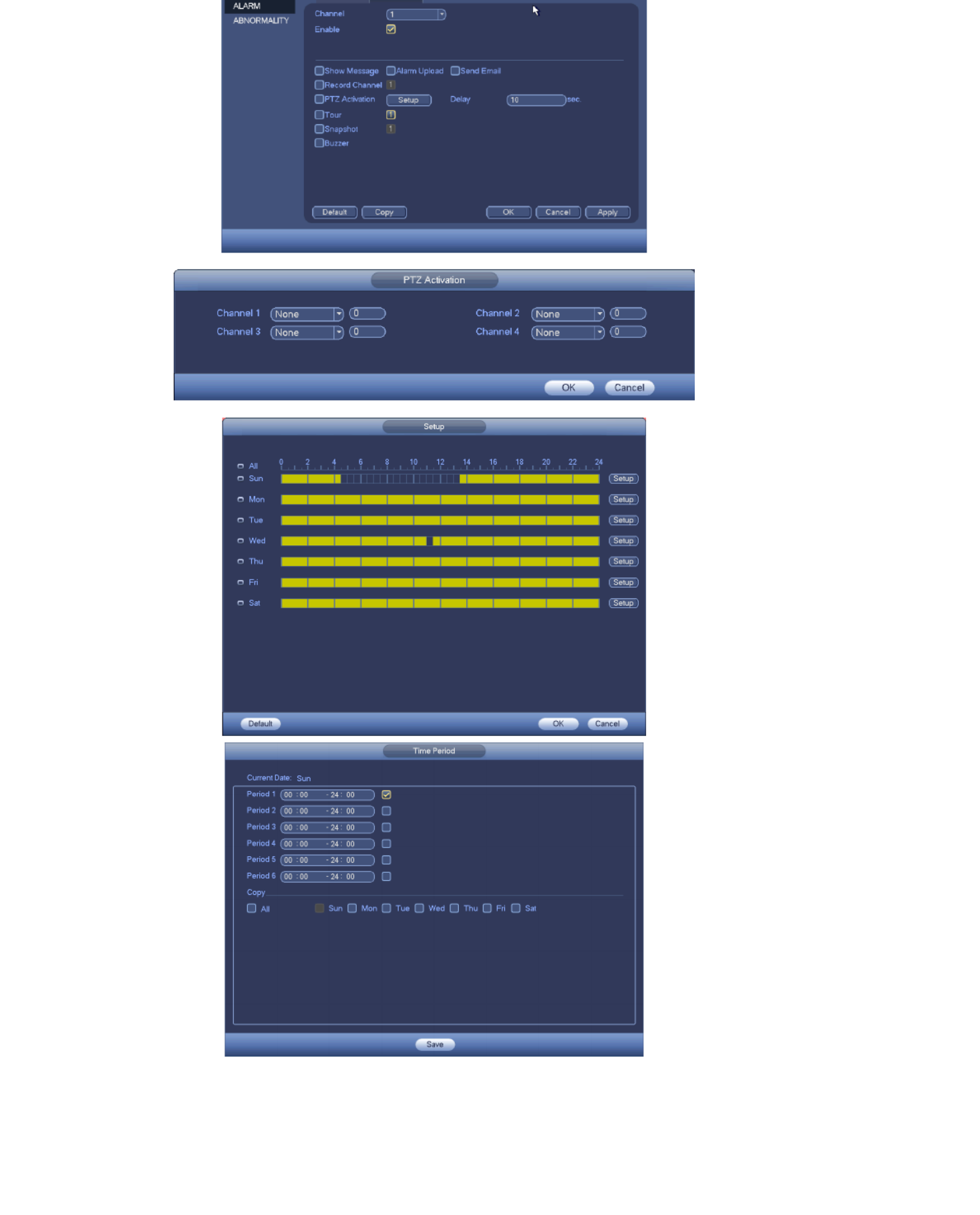
63
Figure 4-84
Figure 4-85
Figure 4-86
Figure 4-87

64
save button, system goes back to the previous menu.
4.10.3 Abnormality
There are two types: /Network. HDD
error, no HDD, no space. See Figure 4- and Figure 4- . HDD HDD: 88 89
Network: Disconnection, IP conflict, MAC conflict. See Figure 4-90.
Less than: System can alarm you when the HDD space is less than the threshold you
set here (For HDD no space type only).
Show message: system can pop up the message in the local screen to alert you when
alarm occurs.
Alarm upload: System can upload the alarm signal to the network (including alarm
centre) if you enabled current function. For disconnection event, IP conflict event and
MAC conflict event, this function is null.
Send email: System can send out email to alert you when alarm occurs.
Buzzer: Highlight the icon to enable this function. The buzzer beeps when alarm an
occurs.
Figure 4-88
Figure 4- 89

65
Figure 4-90
4.11 Network
4.11.1.1 TCP/IP
The single network adapter interface is shown as in Figure 4-91.
Network Mode : Includes multiple access, fault tolerance, and load balancing
IP Version: There are two options: IPv4 and IPv6. Right now, system supports these two
IP address format and you can access via them.
MAC address: The host in the LAN can get a unique MAC address. It is for you to access
in the LAN. It is read-only.
IP address: Here you can use up/down button ( ) or input the corresponding number
to input IP address. Then you can set the corresponding subnet mask the default
gateway.
Default gateway: Here you can input the default gateway. Note system needs to check
the validity of all IPv6 addresses. The IP address and the default gateway shall be in the
same IP section. That is to say, the specified length of the subnet prefix shall have the
same string.
DHCP: It is to auto search IP. When enable DHCP function, you can not modify
IP/Subnet mask /Gateway. These values are from DHCP function. If you have not
enabled DHCP function, IP/Subnet mask/Gateway display as zero. You need to disable
DHCP function to view current IP information. Besides, when PPPoE is operating, you
can not modify IP/Subnet mask /Gateway.
MTU: It is to set MTU value of the network adapter. The value ranges from 1280-7200
bytes. The default setup is 1500 bytes. Note MTU modification may result in network
adapter reboot and network becomes off. That is to say, MTU modification can affect
current network service. System may pop up dialog box for you to confirm setup when
you want to change MTU setup. Click OK button to confirm current reboot, or you can
click Cancel button to terminate current modification. Before the modification, you can
check the MTU of the gateway; the MTU of the -TX 64 shall be the same as or is lower
than the MTU of the gateway. In this way, you can reduce packets and enhance network
transmission efficiency.
The following MTU value is for reference only.
1500: Ethernet information packet max value and it is also the default value. It is the
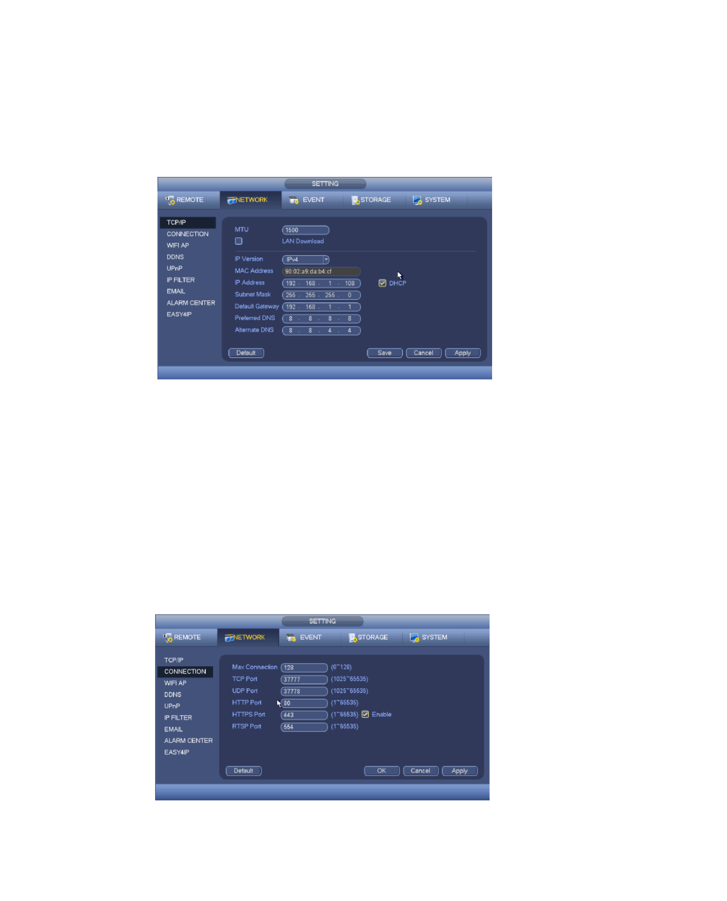
66
1492: Recommend value for PPPoE.
1468: Recommend value for DHCP.
Preferred DNS server: DNS server IP address.
Alternate DNS server: DNS server alternate address.
Transfer mode: Here you can select the priority between fluency/video qualities.
LAN download: System can process the downloaded data first if you enable this
function. The download speed is 1.5X or 2.0X of the normal speed.
After completing all the setups click save button, system goes back to the previous menu.
Figure 4-91
4.11.1.2 Connection
The connection setup interface is shown as in Figure 4-92 .
Max connection: system support maximal 128 users. 0 means there is no connection
limit.
TCP port: Default value is 37777.
UDP port: Default value is 37778.
HTTP port: Default value is 80.
HTTPS port: Default value is 443.
RTSP port: Default value is 554.
Important: System needs to reboot after you changed and saved any setup of the
above fiveports. Make sure the port values here do not conflict.
Figure 4-92

67
This function is for some series product only.
The WIFI AP interface is shown as below. See Figure 4-93. Here you can set WIFI hotspot,
so that the network camera can use the hotspot to connect to the network.
SSID: It is to set SSID name. You can use this name to search the device.
Password: It is to set SSID password. You can use this password to connect to the
network.
Authentication mode: Select authentication from the dropdown list.
Encrypt type: Select encryption type from the dropdown list.
Start IP/End IP: Input start IP and end IP. The - can allocate the IP address in the TX 64
range you specified here.
WPS: Click WPS button to enable WPS function. After the network camera enabled this
function, it can automatically connect to the network.
Remote device: In the list, you can view the network camera(s) that connected to the
TX- . It includes signal intensity, IP, MAC address, bit rate, channel number, type, 64
status and etc.
Figure 4-93
WIFI working status: Here you can view current connection status.
Note:
After successful connection, you can see WIFI connection icon at the top right corner of
the preview interface.
When the hotspot verification type is WEP, system displays as AUTO since the device
can not detect its encryption type.
System does not support verification type WPA and WPA2. The display may become
abnormal for the verification type and encryption type.
After device successfully connected to the WIFI, you can view the hotspot name, IP address,
subnet mask, default gateway and etc.

68
You need a PC of fixed IP in the internet and there is the DDNS software running in this PC.
In other words, this PC is a DNS (domain name server).
In network DDNS, select DDNS type and highlight enable item. And then input your PPPoE
name you get from you IPS and server IP (PC with DDNS). Click save button and then
reboot system.
Click save button, system prompts for rebooting to get all setup activated.
After rebooting, open IE and input as below:
http //(DDNS server IP)/(virtual directory name)/webtest.htm :
e.g.: http //10.6.2.85/ - _DDNS/webtest.htm.) :TX 64
Now you can open DDNSServer web search page.
Figure 4-94
Note S type includes: CN99 DDNS, NO-IP DDNS, Quick DDNS, Dyndns DDNS and DDN
sysdns DDNS. All the DDNS can be valid at the same time, you can select as you
requirement. Private DDNS function shall work with special DDNS server.
Quick DDNS and Client-end Introduction
1) Background Introduction
Device IP is not fixed if you use ADSL to login the network. The DDNS function allows you to
access the TX- via the registered domain name. Besides the general DDNS, the Quick 64
DDNS works with the device from the manufacturer so that it can add the extension function.
2) Function Introduction
The quick DDNS client has the same function as other DDNS client end. It realizes the
bonding of the domain name and the IP address. Right now, current DDNS server is for our
own devices only. You need to refresh the bonding relationship of the domain and the IP
regularly. There is no user name, password or the ID registration on the server. At the same
time, each device has a default domain name (Generated by MAC address) for your option.
You can also use customized valid domain name (has not registered.).
3) Operation
Before you use Quick DDNS, you need to enable this service and set proper server address,
port value and domain name.

69
Domain name There are two modes: Default domain name and customized domain :
name.
Except default domain name registration, you can also use customized domain name (You
can input your self-defined domain name.) After successful registration, you can use
domain name to login installed of the device IP.
User name: It is optional. You can input your commonly used email address.
Important
Do not register frequently. The interval between two registrations shall be more than 60
seconds. Too many registration requests may result in server attack.
System may take back the domain name that is idle for one year. You can get a
notification email before the cancel operation if your email address setup is OK.
4.11.1.5 UPnP
The UPNP protocol is to establish a mapping relationship between the LAN and the WAN
interface see Figure 4- . Input the router IP address in the LAN setting under TCP/IP in 95
Figure 4- . 91
UPNP on/off Turn on or off the UPNP function of the device. :
Status: When the UPNP is offline, it shows as ―Unknown‖. When the UPNP works it
shows ―Success‖
Router LAN IP: It is the router IP in the LAN.
WAN IP: It is the router IP in the WAN.
Port Mapping list The port mapping list here is the one to one relationship with the :
router’s port mapping setting.
List :
Service name Defined by user. :
Protocol Protocol type :
Internal port Port that has been mapped in the router. :
External port Port that has been mapped locally. :
Default: UPNP default port setting is the HTTP, TCP and UDP of the TX- . 64
Add to the list: Click it to add the mapping relationship.
Delete: Click it to remove one mapping item.
Double click one item; you can change the corresponding mapping information. See Figure
4-95.
Important:
When you are setting the router external port, use 1024~5000 port. Do not use
well-known port 1~255 and the system port 256~1023 to avoid conflict. For the TCP
and UDP, make sure the internal port and external port are the same to guarante the
proper data transmission.

70
Figure 4-95
Figure 4-96
4.11.1.6 IP Filter
IP filter interface is shown as in Figure 4-97. You can add IP in the following list. The list
supports max 64 IP addresses. System supports valid address of IPv4 and IPv6. Note
system needs to check the validity of all IPv6 addresses and implement optimization.
After you enabled trusted sites function, only the IP listed below can access current - TX 64.
If you enable blocked sites function, the following listed IP addresses can not access current
TX- . 64
Enable: Highlight the box here, you can check the trusted site function and blocked sites
function. You can not see these two modes if the Enable button is grey.
Type: You can select trusted site and blacklist from the dropdown list. You can view the IP
address on the following column.
Start address/end address: Select one type from the dropdown list, you can input IP
address in the start address and end address. Now you can click Add IP address or Add
IP section to add.
a) For the newly added IP address, it is in enable status by default. Remove the √
before the item, and then current item is not in the list.
b) System max supports 64 items.
c) Address column supports IPv4 or IPv6 format. If it is IPv6 address, system can
optimize it. For example, system can optimize aa:0000: 00: 00aa: 00aa: 00aa: 00aa:
00aa as aa:: aa: aa: aa: aa: aa: aa.
d) System automatically removes space if there is any space before or after the newly

71
and end address if you add IP section and the end address shall be larger than the
start address.
f) System may check newly added IP address exists or not. System does not add if
input IP address does not exist.
Delete: Click it to remove specified item.
Edit: Click it to edit start address and end address. See Figure 4- . System can check 98
the IP address validity after the edit operation and implement IPv6 optimization.
Default: Click it to restore default setup. In this case, the trusted sites and blocked sites
are both null.
Note:
If you enabled trusted sites, only the IP in the trusted sites list can access the device.
If you enabled blocked sites, the IP in the blocked sites can not access the device.
System supports add MAC address.
Figure 4-97
Figure 4- 98
4.11.1.7 Email
The email interface is shown as below. See Figure 4- . 99
SMTP server: Input your email SMTP server IP here.
Port: Input corresponding port value here.
User name: Input the user name to login the sender email box.
Password: Input the corresponding password here.
Sender: Input sender email box here.
Title: Input email subject here. System support English character and Arabic number.
Max 32-digit.
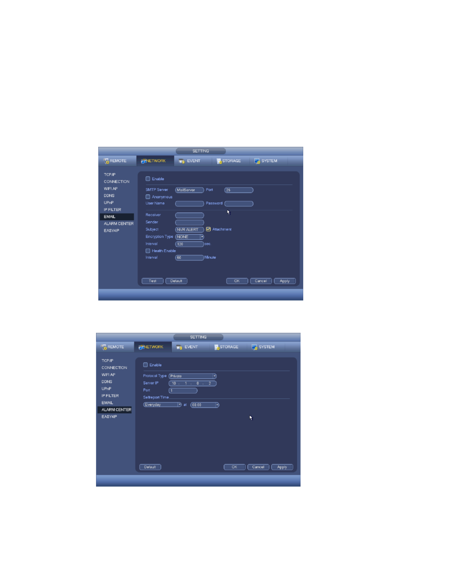
72
SSL enable: System supports SSL encryption box.
Interval: The send interval ranges from 0 to 3600 seconds. 0 means there is no interva l.
Test email enable: Check the box here to enable this function. This function allows the
system to send out the test email to check the connection is OK or not.
Interval: Check the above box to enable this function and then set the corresponding
interval. System can send out the email regularly as you set here. Click the Test button,
you can see the corresponding dialogue box to see the email connection is OK or not.
Note system will not send out the email immediately when the alarm occurs. When the alarm,
motion detection or the abnormity event activates the email, system sends out the email
according to the interval you specified here. This function is very useful when there are too
many emails activated by the abnormity events, which may result in heavy load for the email
server.
Figure 4- 99
4.11.1.8 Alarm Centre
This interface is reserved for you to develop. See Figure 4-100.
Figure 4-100

73
the device over the My Secure Pro App.
Figure 4-101
4.11.2 Network Test
In this interface, you can see network test and network load information.
4.11.2.1 Network Test
From main menu->Info-Network->Test, the network test interface is shown as in Figure
4- 2. 10
Destination IP: Input valid IPV4 address .
Test: Click it to test the connection with the destination IP address. The test results can
display average delay and packet loss rate and you can also view the network status as
OK, bad, no connection and etc.
4.11.2.2 Network Load
From main menu->Info-Network->Load, network load is shown as in Figure 4-102 Here you .
can view the follow statistics of the device network adapter. Here you can view information of
all connected network adapters. The connection status is shown as offline if connection is
disconnected. Click one network adapter, you can view the flow statistics such as send rate
and receive rate at the top panel
Figure 4- 2 10

74
record time and etc. The operation includes format, resume from error, change HDD
property (Read write, Read-only). Here you can also set alarm and HDD storage position.
4.12.1 Format
a) From Main-menu->Setting->Storage->HDD Manager, you can go to HDD
management interface. See Figure 4-103.
Figure 4- 3 10
b) Select a HDD and then select format from the dropdown list. Click Execute button.
c) Click OK button to complete the setup. You can see system needs to restart to activate
current setup.
4.12.2 HDD Information
Here is to list hard disk type, total space, free space, and status. See Figure 4-104
○ means current HDD is normal.. -means there is no HDD.
If disk is damaged, system shows as ―?‖. Remove the broken hard disk before you add a
new one.
Figure 4-104

75
Figure 4-105
Parameter
Function
SATA 3.5‖
1 here means there is 1 . HDD
SN
You can view the HDD amount the device connected to;
﹡ means the second HDD is current working HDD.
Type
The corresponding HDD property.
Total space
The HDD total capacit y.
Free space
The HDD free capacity.
Status
HDD can work properly or not.
Bad track
Display there is bad track or not.
Page up
Click it to view previous page.
Page down
Click it to view the next page.
View
recording
time
Click it to view HDD record information (file start time and end
time).
View HDD
type and
capability
Click it to view HDD property, status and etc,

76
The HDD detect function is to detect HDD current status so that you can clearly understand
the HDD performance and replace the malfunction HDD.
There are two detect types:
Quick detect is to detect via the universal system files. System can quickly complete
the HDD scan. If you want to use this function make sure the HDD is in use now. If ,
the HDD is removed from other device, make sure the write-data once was full after
it installed on current device.
Global detect adopts Windows mode to scan. It may take a long time and may affect
the HDD that is recording.
4.12.3.1 Manual Detect
From main menu->Setting->Storage->HDD Detect->Manual Detect, the interface is shown
as below. See Figure 4-1 . 06
Select detect type and HDD. Click start detect to begin. You can view the corresponding
detect information.
Figure 4-1 06
4.12.3.2 Detect Report
After the detect operation, you can go to the detect report to view corresponding information.
From main menu->Setting->Storage->HDD Detect->Manual Detect, the interface is shown
as below. See Figure 4-1 . 07
Figure 4-1 07

77
Figure 4-1 08
Figure 4-1 09
4.13 Device Setups
4.13.1 General
From Main menu->Setting->System->General, you can go to the general interface. See
Figure 4-110.
Device ID: Input a corresponding device name here.
Device No: When you are using one remote control (not included in the accessory bag)
to control several TX- s, you can give a name to each 64 TX- for your management. 64
Language: System supports various languages English, Italian, Spanish, German, :
Polish, Hungarian, Czech and Dutch (All languages listed here are optional. Slight
difference maybe found in various series.)
Video standard: There are two formats: NTSC and PAL.
HDD full: Here is for you to select working mode when hard disk is full. There are two
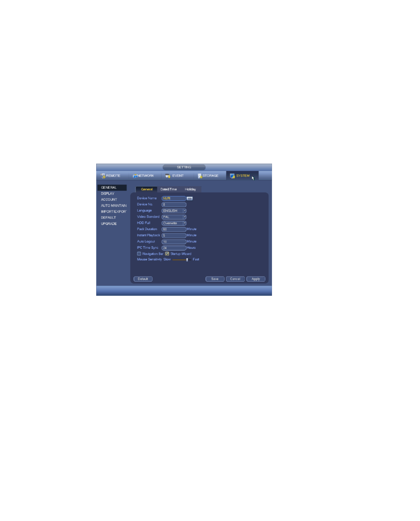
78
HDD is full and then next HDD is not empty, then system overwrites the previous files.
Pack duration: Here is for you to specify record duration. The value ranges from 1 to 120
minutes. Default value is 60 minutes.
Realtime play: It is to set playback time you can view in the preview interface. The value
ranges from 5 to 60 minutes.
Auto logout: Here is for you to set auto logout interval once login user remains inactive for
a specified time. Value ranges from 0 to 60 minutes.
Navigation bar: Check the box here, system displays the navigation bar on the interface.
-CAM Time Sync: You can input an interval here to synchronize the - time and IP TX 64
IP-CAM time.
Startup wizard: Once you check the box here, system will go to the startup wizard directly
when the system restarts the next time. Otherwise, it will go to the login interface.
Mouse property: You can set double click speed via dragging the slide bard. You can
Click Default button to restore default setup.
Figure 4-110
4.13.2 Data and Time
From Main menu->Setting->System->General, you can go to the general interface. See
Figure 4-111.
System time: Here is for you to set system time
Date format: There are three types: YYYYY- -DD: MM- -YYYYY or DD- -YYYY MM DD MM
(default).
Date separator: There are three denotations to separate date: dot, beeline and solidus.
DST: Here you can set DST time (Day Light Saving Time) and date by week or by date.
Enable DST function and then select setup mode. Input start time and end time and click
―Save― button.
Time format: There are two types: 24-hour mode (default) or 12-hour mode.
NTP: It is to set NTP server, port and interval.
Note:
Since system time is very important, do not modify time casually unless there is a must!

79
Figure 4-111
4.13.3 Holiday
Refer to chapter 4.7.6 for detailed information.
4.14 Device Maintenance and Manager
4.14.1 System Info
4.14.1.1 Version
From main menu->In ->System->version, you can go to version interface. fo
Here is for you to view some version information. See Figure 4-112.
Channel System version Build Date, , , Web Serial number ,
Figure 4-112
4.14.1.2 BPS
Here is for you to view current video bit rate (kb/s) and resolution. See Figure 4-113.
Figure 4-113
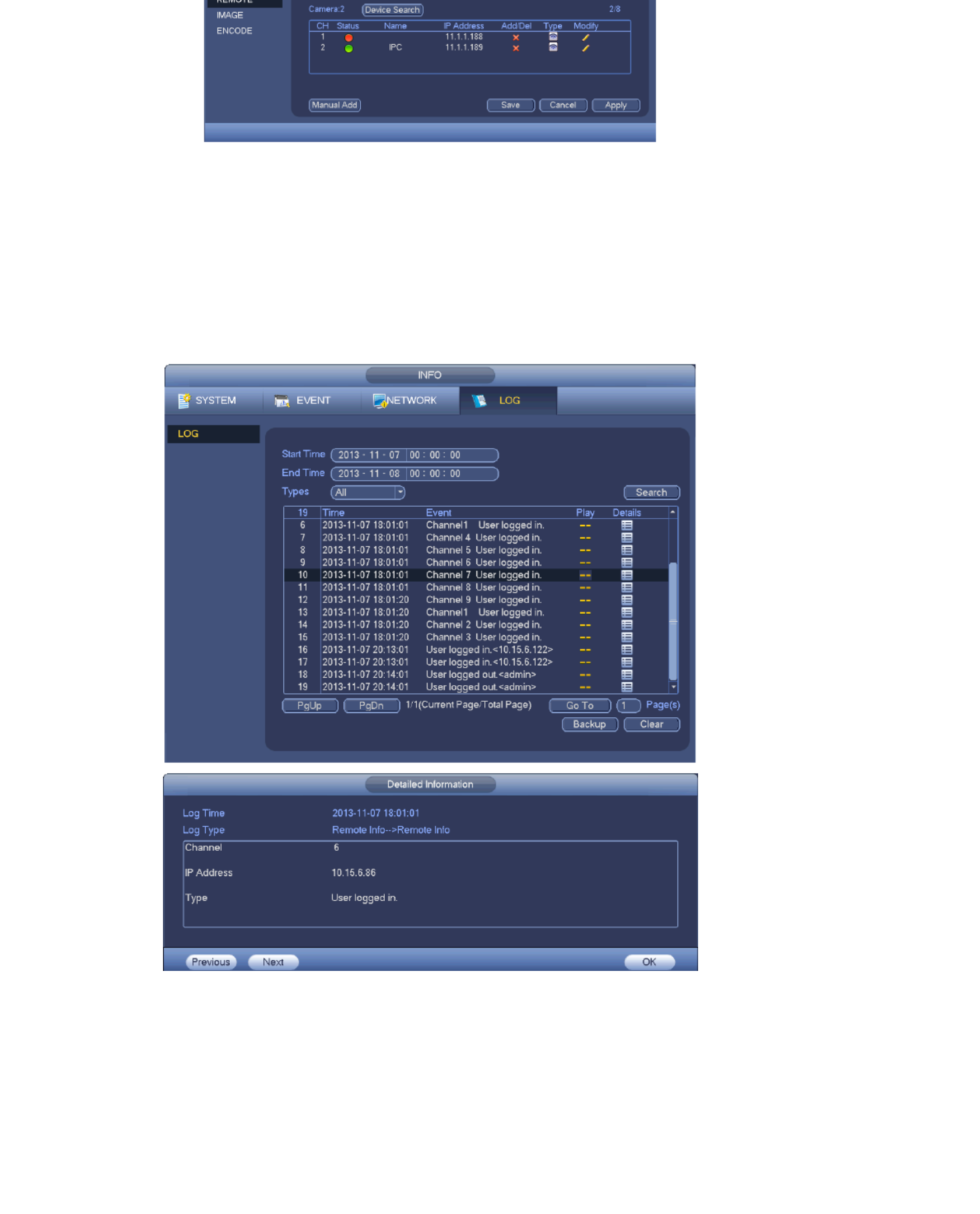
81
Figure 4-116
4.14.2 Log
From Main menu->Info->Log, you can go to the following interface. See Figure 4-118.
Start time/end time: Select start time and end time, then click search button. You can
view the log files in a list. System max displays 100 logs in one page. It can max save
1024 log files. Use page up/down button on the interface to view more.
Tip:
Double click a log item to view its detailed information. See Figure 4-119.
Click PgUp/PgDn to view more logs.
Figure 4-118
Figure 4-119
4.14.3 Account
Here is for you to implement account management. See Figure 4-120 and Figure 4-121.
Here you can:
Add new user

82
Modify group
Modify password.
For account management note:
For the user account name and the user group, the string max length is 6-byte. The
backspace in front of or at the back of the string is invalid. There can be backspace in the
middle. The string includes the valid character, letter, number, underline, subtraction sign,
and dot.
The default user amount is 64 and the default group amount is 20. System account
adopts two-level management: group and user. No limit to group or user amount.
For group or user management, there are two levels: admin and user.
The user name and group name can consist of eight bytes. One name can only be used
once. There are three default users: admin/888888 and hidden user ―default‖.
Hidden user ―default‖ is for system interior use only and can not be deleted. When there
is no login user, hidden user ―default‖ automatically login. You can set some rights such
as monitor for this user so that you can view some channel view without login.
One user should belong to one group. User right can not exceed group right.
About reusable function: this function allows multiple users use the same account to
login.
After all the setups click save button, system goes back to the previous menu.
Figure 4-120
Figure 4-121

83
input group name and then input some memo information if necessary. There are many
rights such as control panel, shut down, real-time monitor, playback, record, record file
backup, PTZ, user account, system information view, system setup, log view, clear log,
upgrade system, control device and etc.
The modify group interface is similar to the Figure 4-122.
Figure 4-122
Tip:
In modify interface, check the modify password box and then input old password and new
password. Input new password again to confirm the modification. The password max has
6-byte and the space in the front or at the end of the string is null. The space is valid only in
the middle of the string. For the account of the Account function, it can change the password
of other users too.
4.14.3.1.2 Add/Modify User
Click add user button. Input the user name, password; select the group it belongs to from the
dropdown list. Then you can check the corresponding rights for current user. For convenient
user management, usually we recommend the general user right is lower than the admin
account. The modify user interface is similar to Figure 4-123.
Figure 4-123

84
With this under menu set the security question so that you can find the password of the
―admin‖ later in emergency case! The modify user interface is similar to Figure 4-124.
Figure 4-124
4.14.4 Update
From Mani menu->Setting->System->Update you can go to the following interface. See ,
Figure 4-125 .
a) Insert USB device that contain the upgrade file.
b) Click Start button and then select the .bin file.
c) You can see the corresponding dialogue box after the update process is complete.
Figure 4-125
4.14.5 Default
You can restore factory default setup to fix some problems when the device is running slowly.
Configuration error occurred. From Main menu->Setting->System->Default, you can go to
the default interface. See Figure 4-1 26.
Click default icon, system pops up a dialogue box. You can highlight to restore factory
default setup. A Camera Network Event Storage, System ll, , , ,
Highlight icon to select the corresponding function. After all the setups click OK button,
system goes back to the previous menu.
Warning!
After you use default function, some your customized setup may lose forever! ink twice Th
before you begin the operation!

85
Figure 4-1 26
4.14.6 Auto Maintain
Here you can set auto-reboot time and auto-delete old files setup. You can set to delete the
files for the specified days. See Figure 4-1 . You can select proper setup from dropdown 27
list. After all the setups click save button, system goes back to the previous menu.
Figure 4-1 27
4.14.7 Logout /Shutdown/Restart
From Ma menu->Operation->Shutdown, you can see an interface shown as in Figure in
4-1 . 28
Shutdown: System shuts down and turns off power.
Logout: Log out menu. You need to input password when you login the next time.
Restart: reboot device.
If you shut down the device, there is a process bar for your reference, system waits for 3
seconds and then shut down (You can not cancel). Note: sometimes you need to input the
proper password to shut down the device.
Figure 4-1 28

86
5.1 General Introduction
The -64 supports access via Browser after installing a web plugin. The Web function TX
provides the following settings: Channel monitor menu tree, search/playback, alarm setup,
system setup, PTZ control and monitor window and etc.
5.1.1 Network Connection
Before log in, make sure:
Network connection is right
-64 and PC network setup is right. Refer to network setup (main menu-> setting-> TX
network)
System can automatically download latest web control and the new version can
overwrite the previous one.
5.1.2 Log in
Open IE/ Mozilla/ Chrome/ Safari and then input the TX-64 IP address in the address column.
For example, if your TX- IP address is 192.168.1.108, then input http:// 192.168.1.108 in 64
IE address column. See Figure below.
Input your IP
address
h
The login interface is shown on
the right.
Please input your user name
and password.
Default factory name is admin
and password is admin.
Note: For security reasons,
please modify your password
after you first login.

87
After you logged in, you can see the main window. See picture below.
Web monitoring window
Note:
This quick start guide is for reference only. Slight difference may be found in user
interface.
All the designs and software here are subject to change without prior written notice.
All trademarks and registered trademarks mentioned are the properties of their
respective owners.
If there is any uncertainty o controversy, refer to the final explanation of us. r
Visit our website or contact your local service engineer for more information.
5.2 LAN Mode
For the LAN mode, after you logged in, you can see the main window. See Figure 5-5.
This main window can be divided into the following sections.
Section 1: There are six function buttons: Live (chapter 0) Setup (chapter 5.8), Info ,
(Chapter 5.9), playback chapter(5.10), alarm (chapter 5.11), and logout (chapter 5.12).
Section 2: There are monitor channels successfully connected to the TX- . 64
Refer to Figure 5-1 below for main stream and extra stream switch information.
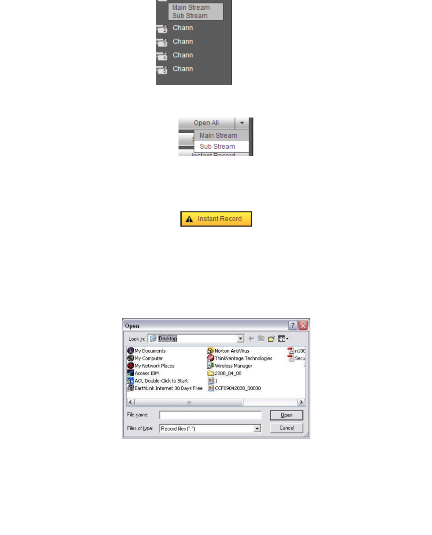
88
Figure 5-1
Section 3: Open all. Open all button is to enable/disable all-channel real-time monitor.
Here you can select main stream/sub stream too. See Figure 5-2 .
Figure 5-2
Section 5: Instant record button. Click it, the button becomes yellow and system begins
manual record. See Figure 5-3. Click it again, system restores previous record mode.
Figure 5-3
Section 6: Local play button.
The Web can playback the saved (Extension name is dav) files in the PC-end.
Click local play button, system pops up the following interface for you to select local play file.
See Figure 5-4.
Figure 5-4
Section 7 Zero-channel encoding. Refer to chapter 5.6 for detailed information. :
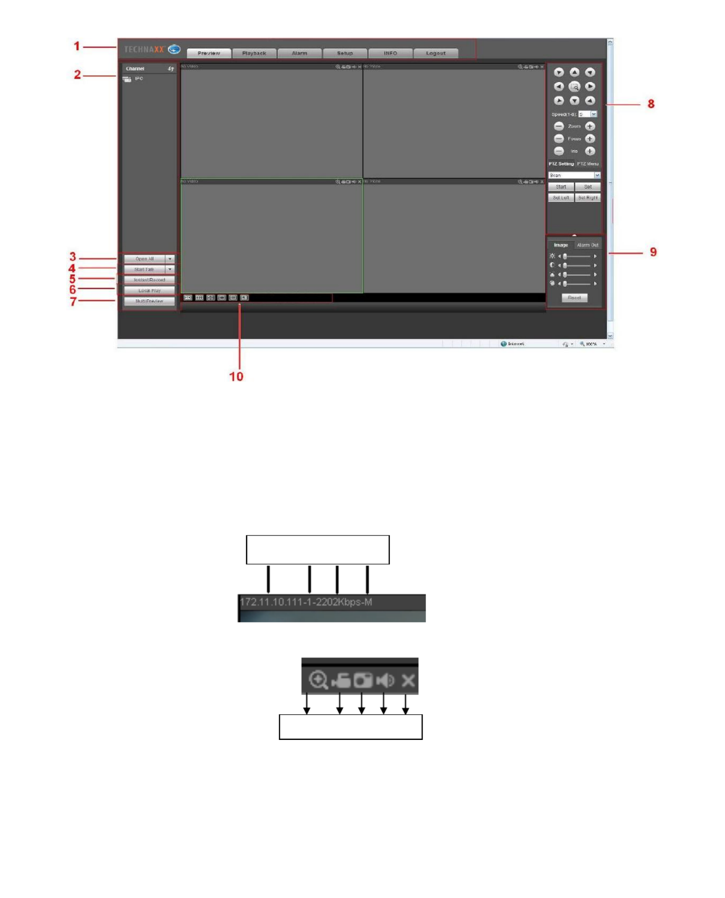
89
Section 10: From the left to the right, you can see video quality/fluency/ full
screen/1-window/4-window. You can set video fluency and real-time feature priority.
Figure 5-5
5.3 Real-time Monitor
In section 2, left click the channel name you want to view, you can see the corresponding
video in current window. On the top left corner, you can view device IP(172.11.10.11)(1),
channel number(2), network monitor bit stream(2202Kbps)(3) and stream type(M=main
stream, S=sub stream)(4). See Figure 5-6.
Figure 5-6
On the top right corner, there are six unction buttons. See .
Figure 5-7
1: Digital zoom: Click this button and then left drag the mouse in the zone to zoom in.
right click mouse system restores original status.
1 2 3 4 5
1 2 3 4

90
recorded file.
3: Snapshot picture. You can snapshot important video. All images are memorized in
system client folder PictureDownload (default).
4: Audio :Turn on or off audio.(It has no relationship with system audio setup )
5: Close video.
5.4 PTZ
Before PTZ operation, make sure you have properly set PTZ protocol.
There are eight direction keys. In the middle of the eight direction keys, there is a 3D
intelligent positioning key.
Click 3D intelligent positioning key, system goes back to the single screen mode. Drag the
mouse in the screen to adjust section size. It can realize PTZ automatically.
Refer to the following sheet for PTZ setup information.
Parameter
Function
Scan
Select Scan from the dropdown list.
Click Set button, you can set scan left and right limit.
Use direction buttons to move the camera to you desired location and
then click left limit button. Then move the camera again and then click
right limit button to set a right limit.
Preset
Select Preset from the dropdown list.
Turn the camera to the corresponding position and Input the preset
value. Click Add button to add a preset.
Tour
Select Tour from the dropdown list.
Input preset value in the column. Click Add preset button, you have
added one preset in the tour.
Repeat the above procedures you can add more presets in one tour.
Or you can click delete preset button to remove one preset from the
tour.
Pattern
(optional)
Select Pattern from the dropdown list.
You can input pattern value and then click Start button to begin PTZ
movement such as zoom, focus, iris, direction and etc. Then you can
click Add button to set one pattern.
Aux
(optional)
Input the corresponding aux value here.
You can select one option and then click AUX on or AUX off button.
Light
(optional)
You can turn on or turn off the light.

92
Figure 5- 11
Refer to the following contents for LAN and WAN login difference.
1) In the WAN mode, system opens the main stream of the first channel to monitor by default.
The open/close button on the left pane is null.
2) You can select different channels and different monitor modes at the bottom of the
interface. See Figure 5- . 12
Figure 5- 12
Important
The window display mode and the channel number are by default. For example, for
the 4-channel, the max window split mode is 4 .
3) Multiple-channel monitor, system adopts extra stream to monitor by default. Double click
one channel, system switches to single channel and system uses main stream to monitor.
You can view there are two icons at the left top corner of the channel number for you

94
Device
search
Click Device search button, you can view the searched device
information on the list. It includes device IP address, port, device
name, manufacturer and type.
Add
Select a device in the list and then click Add button, system can
connect the device automatically and add it to the Added device
list. Or you can double click one item in the list to add a device.
Modify
Click or any device in the Added device list, you can
change the corresponding channel setup.
Delete
Click , you can delete the remote connection of the
corresponding channel.
Connection
status
: Connection succeeded.
: Connection failed.
Delete
Select a device in the Added device list and then click Delete
button, system can disconnect the device and remove it from
the Added device list.
Manual Add
Click it, the interface is shown as in Figure 5- . Here you can 14
add network camera manually.
You can select a channel from the dropdown list (Here only
shows disconnection channel.)
Note:
System supports manufactures such as Panasonic, Sony,
Dynacolor, Samsung, AXIS, Arecont, Dahua and Onvif
standard protocol.
If you do not input IP address here. System uses default IP
192.168.0.0 and system does not connect to this IP.
Can not add two devices at the same time. Click OK button
here, system only connect to the corresponding device of
current channel.
5.8.1.2 Image
Note:
Slight difference may be found since the connected network camera may not be same
model .
Here you can view device property information. The setups become valid immediately after
you set. See Figure 5- . 15

95
Figure 5- 15
Refer to the following sheet for detailed information.
Parameter
Function
Channel
Select a channel from the dropdown list.
Period
It divides one day (24 hours) to two periods. You can set different hue,
brightness, and contrast for different periods.
Hue
(optional)
It is to adjust monitor video brightness and darkness level. The default
value is 50.
The bigger the value is, the large the contrast between the bright and dark
section is and vice versa.
Saturation
It is to adjust monitor window saturation. The value ranges from 0 to 100.
The default value is 50.
The larger the number is, the strong the color is. This value has no effect
on the general brightness of the whole video. The video color may become
too strong if the value is too high. For the grey part of the video, the
distortion may occur if the white balance is not accurate. Note the video
may not be attractive if the value is too low. The recommended value
ranges from 40 to 60.
Brightness
It is to adjust monitor window brightness. The default value is 50.
The larger the number is , the bright the video is. When you input the value
here, the bright section and the dark section of the video will be adjusted
accordingly. You can use this function when the whole video is too dark or
too bright. Note the video may become hazy if the value is too high. The
value ranges from 0 to 100.The recommended value ranges from 40 to 60.
Contrast
It is to adjust monitor window contrast. The value ranges from 0 to 100.
The default value is 50.
The larger the number is, the higher the contrast is. You can use this
function when the whole video bright is OK but the contrast is not proper.
Note the video may become hazy if the value is too low. If this value is too
high, the dark section may lack brightness while the bright section may
over exposure .The recommended value ranges from 40 to 60.

96
value here, the bright section and the dark section of the video will be
adjusted accordingly. You can use this function when the whole video is
too dark or too bright. Note the video may become hazy if the value is too
high. The value ranges from 0 to 100.The recommended value ranges
from 40 to 60.
White level
(optional)
It is to enhance video effect.
Color
mode
(optional)
It includes several modes such as standard, color. You can select
corresponding color mode here, you can see hue, brightness, and contrast
and etc will adjust accordingly.
Auto Iris
(optional)
It is to enable/disable auto iris function.
Flip
It is to switch video up and bottom limit.
This function is disabled by default.
Mirror
It is to switch video left and right limit.
This function is disabled by default.
BLC Mode
(optional)
BLC
The device auto exposures according to the environments
situation so that the darkest area of the video is cleared
WDR
For the WDR scene, this function can lower the high bright section
and enhance the brightness of the low bright section. So that you
can view these two sections clearly at the same time.
The value ranges from 1 to 100. When you switch the camera
from no-WDR mode to the WDR mode, system may lose several
seconds record video.
HLC
After you enabled HLC function, the device can lower the
brightness of the brightest section according to the HLC control
level. It can reduce the area of the halo and lower the brightness
of the whole video.
Off
It is to disable the BLC function. Note this function is disabled by
default.
Profile
(optional)
It is to set the white balance mode. It has effect on the general hue of the
video. This function is on by default.
You can select the different scene mode such as auto, sunny, cloudy,
home, office, night, disable and etc to adjust the video to the best quality.
Auto: The auto white balance is on. System can auto compensate the
color temperature to make sure the vide color is proper.
Sunny: The threshold of the white balance is in the sunny mode.
Night: The threshold of the white balance is in the night mode.
Customized: You can set the gain of the red/blue channel. The value

97
auto.
Color: Device outputs the color video.
Auto: Device auto select to output the color or the B/W video
according to the device feature (The general bright of the video or
there is IR light or not.)
B/W: The device outputs the black and white video.
Sensor: It is to set when there is peripheral connected IR light.
5.8.1.3 Encode
5.8.1.3.1 Encode
The encode interface is shown as below. See Figure 5- . 16
Figure 5- 16
Refer to the following sheet for detailed information.
Parameter
Function
Channel
Select a channel from the dropdown list.
Video enable
Check the box here to enable extra stream video. This item is
enabled by default.
Code stream type
It includes main stream, motion stream and alarm stream. You
can select different encode frame rates form different recorded
events.
System supports active control frame function (ACF). It allows
you to record in different frame rates.
For example, you can use high frame rate to record important
events, record scheduled event in lower frame rate and it
allows you to set different frame rates for motion detection
record and alarm record.
Compression
The main bit stream supports H.264 with 1080P as max.
resolution. The extra stream supports H.264, MJPEG with D1

98
Resolution
p y
camera.
Frame Rate PAL: ~ ; : ~1 25f/s NTSC 1 30f/s.
Bit Rate Type Main stream: You can set bit rate here to change video
quality. The larger the bit rate is, the better the quality is.
Refer to recommend bit rate for the detailed information.
Extra stream: In CBR, the bit rate here is the max value.
In dynamic video, system needs to low frame rate or
video quality to guarantee the value. The value is null in
VBR mode.
Reference bit rate
Recommended bit rate value according to the resolution and
frame rate you have set.
Audiod
Enable Audio for Main Stream or Extra Stream
Watermark enable
This function allows you to verify the video is tampered or not.
Here you can select watermark bit stream, watermark mode
and watermark character. The max length is 85-digit. The
character can only include number, character and underline.
5.8.1.3.2 Snapshot
The snapshot interface is shown as in Figure 5- . 17
Figure 5- 17
Refer to the following sheet for detailed information.
Parameter
Function
Snapshot type
There are two modes: Regular (schedule) and Trigger.
Regular snapshot is valid during the specified period you set.
Trigger snapshot only is valid when motion detect alarm, tampering
alarm or local activation alarm occurs.
Image size
It is the same with the resolution of the main stream.
Quality
It is to set the image quality. There are six levels.
Interval
It is to set snapshot frequency. The value ranges from 1s to 7s.
Or you can set customized value. The max setup is 3600s/picture.
Copy
Click it; you can copy current channel setup to other channel(s).
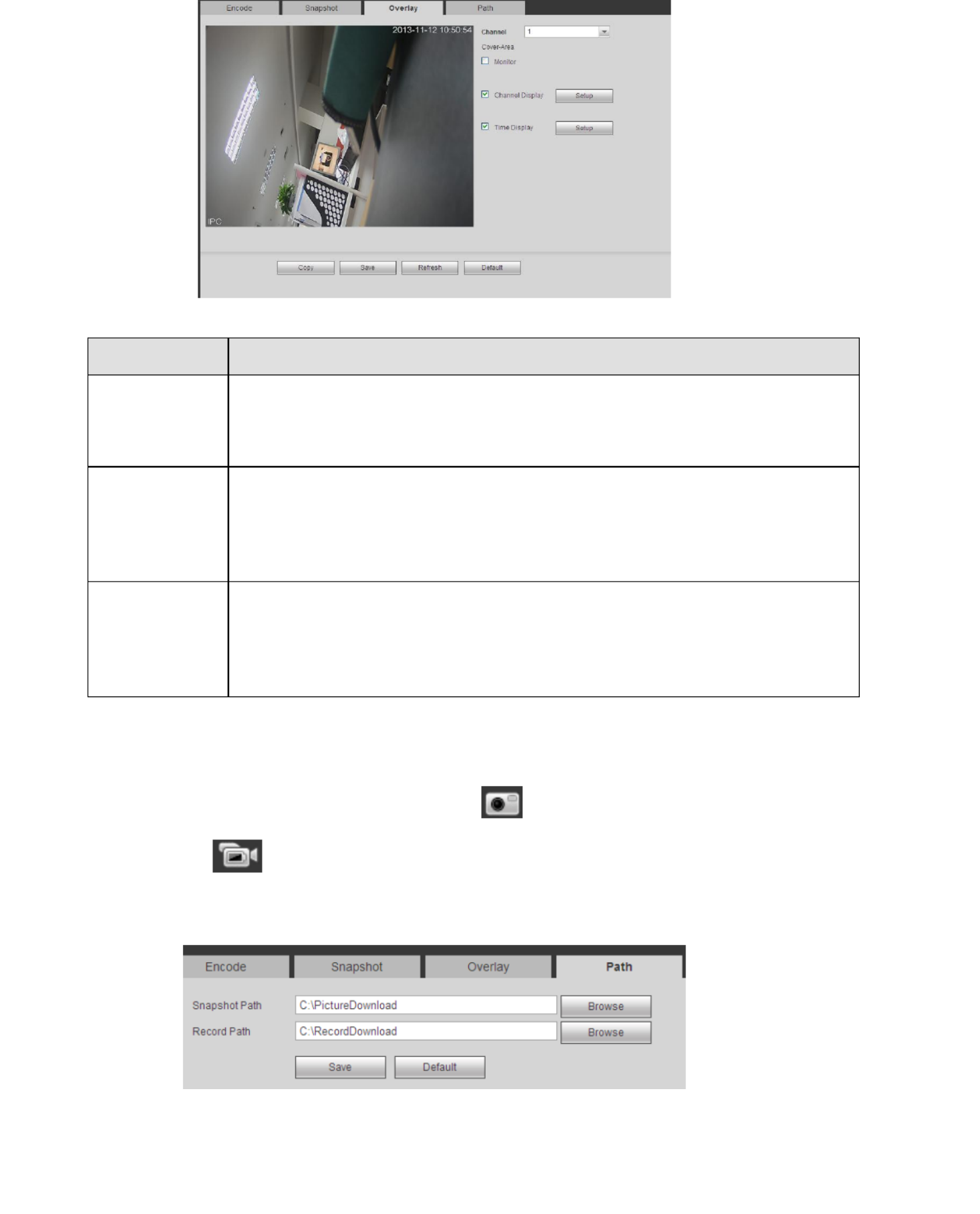
99
Figure 5- 18
Refer to the following sheet for detailed information.
Parameter
Function
Cover-area
Check Preview or Monitor first.
Click Set button, you can privacy mask the specified video in the
preview or monitor video.
System max supports 4 privacy mask zones.
Time Title
You can enable this function so that system overlays time information
in video window.
You can use the mouse to drag the time title position.
You can view time title on the live video of the WEB or the playback
video.
Channel Title
You can enable this function so that system overlays channel
information in video window.
You can use the mouse to drag the channel title position.
You can view channel title on the live video of the WEB or the playback
video.
5.8.1.3.4 Path
The storage path interface is shown as in Figure 5- . 19
Here you can set snap image saved path ( in the preview interface) and the record
storage path ( in the preview interface).The default setup is C:\PictureDownload and
C:\RecordDownload.
Click the Save button to save current setup.
Figure 5- 19

100
Figure 5- 20
5.8.1.5 -CAM Upgrade IP
This interface is to upgrade network camera. See Figure 5- . 21
Click Browse button to select upgrade file. Or you can use filter to select several network
cameras at the same time.
Figure 5- 21
5.8.2 Network
5.8.2.1 TCP/IP
The TCP/IP interface is shown as in Figure 5- . 22
Figure 5- 22

101
Mode There are two modes: static mode and the DHCP mode.
The IP/submask/gateway are null when you select the DHCP
mode to auto search the IP.
If you select the static mode, you need to set the
IP/submask/gateway manually.
If you select the DHCP mode, you can view the
IP/submask/gateway from the DHCP.
If you switch from the DHCP mode to the static mode, you
need to reset the IP parameters.
Besides, IP/submask/gateway and DHCP are read-only when
the PPPoE dial is OK.
Mac Address
It is to display host Mac address.
IP Version
It is to select IP version. IPV4 or IPV6.
You can access the IP address of these two versions.
IP Address
Use the keyboard to input the corresponding number to modify
the IP address and then set the corresponding subnet mask and
the default gateway.
Subnet Mask
If modus set to DHCP than the subnetmask is filled in
automatically.
Default Gateway
Mostly this is the IP of your router. Under DHCP Default gateway
is filled in automatically.
Preferred DNS
DNS IP address.
Alternate DNS
Alternate DNS IP address.
For the IP address of IPv6 version, default gateway, preferred DNS and
alternate DNS, the input value shall be 128-digit. It shall not be left in blank.
LAN Download
System can process the downloaded data first if you enable this
function. The download speed is 1.5X or 2.0X of the normal
speed.
5.8.2.2 Connection
The connection interface is shown as in Figure 5- . 23
Figure 5- 23

102
Max connection It is the max Web connection for the same device. The value ranges
from 1 to 128. The default setup is 128.
TCP port The default value is 37777. You can input the actual port number if
necessary.
UDP port
The default value is 37778. You can input the actual port number if
necessar y.
HTTP port
The default value is 80. You can input the actual port number if
necessary.
HTTPS
The default value is 443. You can input the actual port number if
necessary.
RTSP port
The default value is 554.
5.8.2.3 HTTPS
In this interface, you can set to make sure the PC can successfully login via the HTTPS. It is
to guarantee communication data security. The reliable and stable technology can secure
the user information security and device safety. See Figure 5-24.
Note
You need to implement server certificate again if you have changed device IP.
You need to download root certificate if it is your first time to use HTTPS on
current PC.
Figure 5- 24
5.8.2.4 PPPoE
The PPPoE interface is shown as in Figure 5- . Input the PPPoE user name and password 25
you get from the IPS (internet service provider) and enable PPPoE function. Save current
setup and then reboot the device to get the setup activated. Device connects to the internet
via PPPoE after reboot. You can get the IP address in the WAN from the IP address column.
Note, you need to use previous IP address in the LAN to login the device. Go to the IP
address item to via the device current device information. You can access the
client-end via this new address.

103
Figure 5- 25
5.8.2.5 DDNS
The DDNS interface is shown as in Figure 5- . 26
The DDNS is to set to connect the various servers so that you can access the system via the
server. Go to the corresponding service website to apply a domain name and then access
the system via the domain. It works even your IP address has changed. Select DDNS from
the dropdown list (Multiple choices). Before you use this function, make sure your purchased
device support current function.
Figure 5- 26
Refer to the following sheet for detailed information.
Parameter
Function
Server Type
You can select DDNS protocol from the dropdown list and then
enable DDNS function.
Server IP
DDNS server IP address
Server Port
DDNS server port.
Domain Name
Your self-defined domain name.
User
The user name you input to log in the server.
Password
The password you input to log in the server.
Update period
Device sends out alive signal to the server regularly.
You can set interval value between the device and DDNS server
here.

104
Device IP is not fixed if you use ADSL to login the network. The DDNS function allows you to
access the - via the registered domain name. Besides the general DDNS, the quick TX 64
DDNS works with the device from the manufacturer so that it can add the extension function.
2) Function Introduction
The quick DDNS client has the same function as other DDNS client end. It realizes the
bonding of the domain name and the IP address. You need to refresh the bonding
relationship of the domain and the IP regularly. There is no user name, password or the ID
registration on the server. At the same time, each device has a default domain name
(Generated by MAC address) for your option. You can also use customized valid domain
name (has not registered.).
3) Operation
Before you use Quick DDNS, you need to enable this service and set proper server address,
port value and domain name.
Server address www.quickddns.com :
Port number :80
Domain name There are two modes: Default domain name and customized domain :
name.
Except default domain name registration, you can also use customized domain name (You
can input your self-defined domain name.) After successful registration, you can use
domain name to login installed of the device IP.
User name: It is optional. You can input your commonly used email address.
Important
Do not register frequently. The interval between two registrations shall be more than 60
seconds. Too many registration requests may result in server attack.
System may take back the domain name that is idle for one year. You can get a
notification email before the cancel operation if your email address setup is OK.
5.8.2.6 IP filter
The IP filter interface is shown as in Figure 5- . 27
After you enabled trusted sites function, only the IP listed below can access current TX- . If 64
you enable blocked sites function, the following listed IP addresses can not access current
TX- . 64
Figure 5- 27

105
Figure 5- 28
Refer to the following sheet for detailed information.
Parameter
Function
Enable
Check the box here to enable email function.
SMTP Server
Insert the SMTP server address of your mail account .
Port
Default value is 25. You can modify it if necessary.
Anonymity
For the server supports the anonymity function. You can auto login
anonymously. You do not need to input the user name. password and
the sender information.
User Name
The user name of the sender email account.
Password
The password of sender email account.
Sender
Sender email address who should receive the message.
Authentication
(Encryption
mode)
You can select TLS, SSL or none. (Look up which authentication your
E-mail host (gmail; outlook, etc.) supports and fill it in.)
Subject
Input email subject here.
Attachment
System can send out the email of the snapshot picture once you check
the box here.
Receiver
Input receiver email address here. Max three addresses.
It supports SSL, TLS email box.
Interval
The send interval ranges from 0 to 3600 seconds. 0 means there is no
interval.
Note system will not send out the email immediately when the alarm
occurs. When the alarm, motion detection or the abnormity event
activates the email, system sends out the email according to the
interval you specified here. This function is very useful when there are
too many emails activated by the abnormity events, which may result in
heavy load for the email server.

106
enable
Update period
(interval)
This function allows the system to send out the test email to check the
connection is OK or not.
Check the box to enable this function and then set the corresponding
interval. The value ranges from 30 minutes to 1440 minutes.
System can send out the email regularly as you set here.
Email test
The system will automatically sent out a email once to test the
connection is OK or not .Before the email test, save the email setup
information.
5.8.2.8 FTP
The FTP interface is shown as in Figure 5-29. It is to set FTP IP, port and etc for remote
storage.
Figure 5- 29
5.8.2.9 UPnP
It allows you to establish the mapping relationship between the LAN and the public network.
Here you can also add, modify or remove UPnP item. See Figure 5- . 30
In the Windows OS, From Start->Control Panel->Add or remove programs. Click the
―Add/Remove Windows Components‖ and then select the ―Network Services‖ from the
Windows Components Wizard.
Click the Details button and then check the ―Internet Gateway Device Discovery and
Control client‖ and ―UPnP User Interface‖. Click OK to begin installation.
Enable UPnP from the Web. If your UPnP is enabled in the Windows OS, the TX- can 64
auto detect it via the ―My Network Places‖

107
Figure 5- 30
Refer to the following sheet for detailed information .
Parameter
Function
PAT
Check the corresponding box to enable PAT function.
Status
Dsiplay UPnP function status.
Port mappling list
It is corresponding to the UPnP mapping information on the router.
Check the box before the service name to enable current PAT
service. Otherwise, the service is null.
Service name Custmozied name. :
Prptocol Protocol type. :
Internal port The port maped to the port. :
External port The port current device needs to map. :
Device has three mapping items: HTTP/TCP/UDP.
Note
When you set the external port (outport) of the router, the value
ranges from 1024 to 5000. Do not use port 1 255 or system port ~
256~1023, in case there is conflict.
Add
Click Add button to add map relationship.
Note
For the data transmission protocol TCP/UDP, the external port and
the internal port shall be the same to guarantee proper data
transmission.
Delete
Select ona service and then click to delete map relationship.
Refer to the following sheet for detailed information.
Parameter
Function
SNMP Port
The listening port of the proxy program of the device. It is a UDP port
not a TCP port. The value ranges from 1 to 65535. The default value is
161
Read
Community
It is a string. It is a command between the manage process and the
proxy process. It defined the authentication, access control and the
management relationship between one proxy and one group of the

108
The read community will read all the objects the SNMP supported in
the specified name. The default setup is public.
Write
Community
It is a string. It is a command between the manage process and the
proxy process. It defined the authentication, access control and the
management relationship between one proxy and one group of the
managers. Make sure the device and the proxy are the same.
The read community will read/write/access all the objects the SNMP
supported in the specified name. The default setup is write.
Trap address
The destination address of the Trap information from the proxy
program of the device.
Trap port
The destination port of the Trap information from the proxy program of
the device. It is for the gateway device and the client-end PC in the
LAN to exchange the information. It is a non-protocol connection port.
It has no effect on the network applications. It is a UDP port not TCP
port. The value ranges from 1 to 165535. The default value is 162.
SNMP version
Check V1, system only processes the information of V1.
Check V2, system only processes the information of V2.
5.8.2.10 Multicast
The multicast interface is shown as in Figure 5-31 Multicast is a transmission mode of data
packet. When there is multiple-host to receive the same data packet, multiple-cast is the
best option to reduce the broad width and the CPU load. The source host can just send out
one data to transit. This function also depends on the relationship of the group member and
group of the outer.
Figure 5- 31
5.8.2.11 Alarm Center (optional)
The alarm center interface is shown as below. See Figure 5-32. This interface is reserved for
you to develop. System can upload alarm signal to the alarm center when local alarm occurs.
Before you use alarm center, set server IP, port and etc. When an alarm occurs, system can
send out data as the protocol defined, so the client-end can get the data.
Figure 5- 32

109
You can scan the QR code to connect the receiver with the MY Secure Pro App.
Figure 5- 33
5.8.3 Event
5.8.3.1 Video detect
5.8.3.1.1 Motion Detect
Tip: Set the sensitivity and the threshold under region in order to get an alarm when the
detected moving signal reached the threshold you set in the device.
The motion detect interface is shown as in Figure 5-34.
Figure 5- 34

110
Enable You need to check the box to enable motion detection function.
Select a channel from the dropdown list. See Figure 5- . 35
Period Motion detection function becomes activated in the specified periods.
See Figure 5- below. 35
There are six periods in one day. Draw a circle to enable corresponding
period.
Click OK button, system goes back to motion detection interface; click
save button to exit.
Anti-dither
System only memorizes one event during the anti-dither period. The
value ranges from 5s to 600s.
Region
If you select motion detection type, you can click this button to set
motion detection zone. The interface is shown as in Figure 5-36. Here
you can set motion detection regions. There are four regions for you to
set (red, yellow, blue and green). Select one of the colored regions first.
Then click the left mouse button on the start point of the area you want
to select and drag the mouse to select the area. In the test area the
best setting for sensitivity and threshold is 60 and 10 respectively.
Depending on your given environment this settings can be vary.
Sensitivity and threshold can be set in the range from 0 to 100. The
higher the sensitivity and the lower the threshold are set the more
motion is detected. For example: When a leaf falls or a cat is running in
the selected area a motion will be detected.
In this case a subjective setting by the customer is requested!
The corresponding colored area displays different detection areas.
After you completed the setup remember to click the save button to
save current setup. If you click ESC button to exit the region setup
interface system will not save your zone setup.
Record
channel
System auto activates motion detection channel(s) to record once an
alarm occurs. Note you need to set motion detect record period and go
to Storage-> Schedule to set current channel as schedule record.
Record Delay
System can delay the record for specified time after alarm ended. The
value ranges from 10s to 300s.
Alarm out
(optional)
Enable alarm activation function. You need to select alarm output port
so that system can activate corresponding alarm device when an alarm
occurs.
Latch
(optional)
System can delay the alarm output for specified time after an alarm
ended. The value ranges from 1s to 300s.
Show
message
System can pop up a message to alarm you in the local host screen if
you enabled this function.

111
p
alarm occurs.
Alarm upload System can upload the alarm signal to the centre (Including alarm
centre.
Send Email
If you enabled this function, System can send out an email to alert you
when an alarm occurs.
PTZ
Activation
Here you can set PTZ movement when alarm occurs. Such as go to
preset X. See Figure 5- 37.
Tour
You need to click setup button to select tour channel. System begins
1-wiindow or multiple-window tour display among the channel(s) you
set to record when an alarm occurs. See Figure 5- . 38
Snapshot
Click setup button to select snapshot channel. See Figure 5- 39.
Video Matrix
(optional)
This function is for motion detect only. Check the box here to enable
video matrix function. Right now system supports one-channel tour
function. System takes ―first come and first serve‖ principle to deal with
the activated tour. System will process the new tour when a new alarm
occurs after previous alarm ended. Otherwise it restores the previous
output status before the alarm activation.
Figure 5- 35
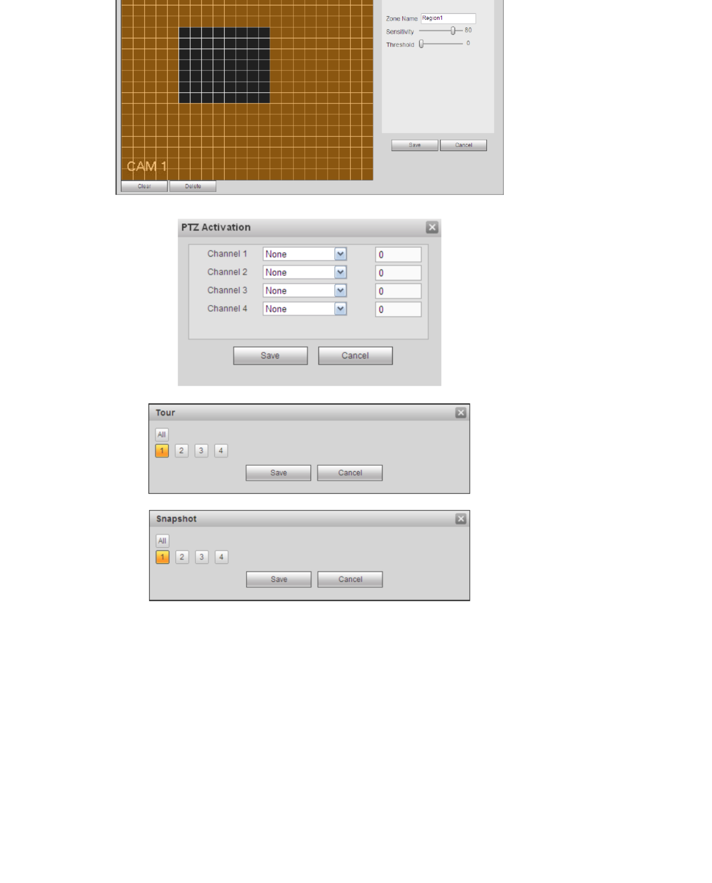
112
Figure 5- 36
Figure 5- 37
Figure 5- 38
Figure 5- 39
5.8.3.1.2 Video Loss
The video loss interface is shown as in Figure 5- Note video loss does not support 40.
anti-dither, sensitivity, region setup. For rest setups, refer to chapter 5.8.3.1.1 motion detect
for detailed information.
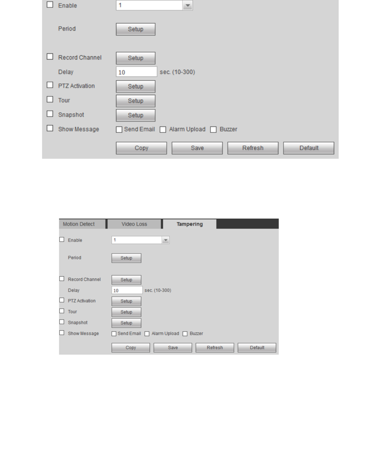
113
Figure 5- 40
5.8.3.1.3 Tampering
The tampering interface is shown as in Figure 5- After analysis video, system can 41.
generate a tampering alarm when the detected moving signal reached the sensitivity you set
here. For detailed setups, refer to chapter 5.8.3.1.1 motion detect for detailed information.
Figure 5- 41
5.8.3.2 Alarm
Before operation, make sure you have properly connected alarm devices such as buzzer.
5.8.3.2.1 C External A rm (optional) IP la
The IPC External Alarm interface is shown as in Figure 5-42. Network alarm refers to the
alarm signal from the network. System does not anti-dither and sensor type setup.

115
Figure 5- 45
Figure 5- 46
Figure 5- 47
Figure 5- 48
Figure 5- 49
Refer to the following sheet for detailed information.
Parameter
Function
Event Type
The abnormal events include: No disk, disk error, disk no space, net
disconnection, IP conflict and MAC conflict.
You can set one or more items here.
Less than: You can set the minimum percentage value here (For disk not
space only). The device can alarm when capacity is not sufficient.
You need to draw a circle to enable this function.

116
Show
message System can pop up a message to alarm you in the local host screen if
you enabled this function.
Alarm upload
System can upload the alarm signal to the centre (Including alarm centre.
Send Email
If you enabled this function, System can send out an email to alert you
when an alarm occurs.
Buzzer
Check the box here to enable this function. The buzzer beeps when an
alarm occurs.
5.8.4 Storage
5.8.4.1 Schedule
In this interfaces, you can add or remove the schedule record setup and snapshot. See
Figure5- 50.
There are four record modes: general (auto), motion detect, alarm and MD & alarm.
There are six periods in one day. You can view the current time period setup from the color
bar.
Green color stands for the general record/snapshot.
Yellow color stands for the motion detect record/snapshot.
Red color stands for the alarm record/snapshot.
Blue color stands for MD & alarm record/snapshot.
Click on the button ―Setting‖ in Figure 5- to see Figure 5- . Refer to the table below to 50 51
see the describtion of the functions.
Figure 5- Figure 5- 50 51
Click on the button ―Copy‖ in Figure 5- and you get the option to copy the settings from on 50
camera to all or just one other. See Figure 5- . 52

117
Figur 5- e 52
Refer to the following sheet for detailed information.
Parameter
Function
Channel
Select a channel from the dropdown list. Figure 5- 50
Pre-record
Input pre-record time here. The value ranges from 0 to 30.
Figure 5- . 50
Redundancy
Check the box here to enable redundancy function. Note this
function is null if there is only one HDD. Figure 5- . 50
Snapshot
Check the box here to enable snapshot function.
Holiday
Check the box here to enable holiday function.
Setup
Click the Setup button, you can set record period. See Figure
5- There are six periods in one day. If you do not check the 50.
date at the bottom of the interface, current setup is for today
only.
Click Save button and then exit.
C opy
Copy function allows you to copy one channel setup to another.
After setting in channel, click Copy button, you can go to
interface Figure 5-52. You can see current channel name is
grey such as channel 1. Now you can select the channel you
wan to paste such as channel 2/3/4. If you wan to save current
setup of channel 1 to all channels, you can click the first box
―ALL‖. Click the OK button to save current copy setup. Click the
OK button in the Encode interface, the copy function
succeeded.
5.8.4.2 Storage Media
5.8.4.2.1 Local Storage
The local interface is shown as in Figure 5-53. Here you can see HDD information. You can
also operate the read-only, read-write, redundancy (if there are more than on HDD) and
format operation.
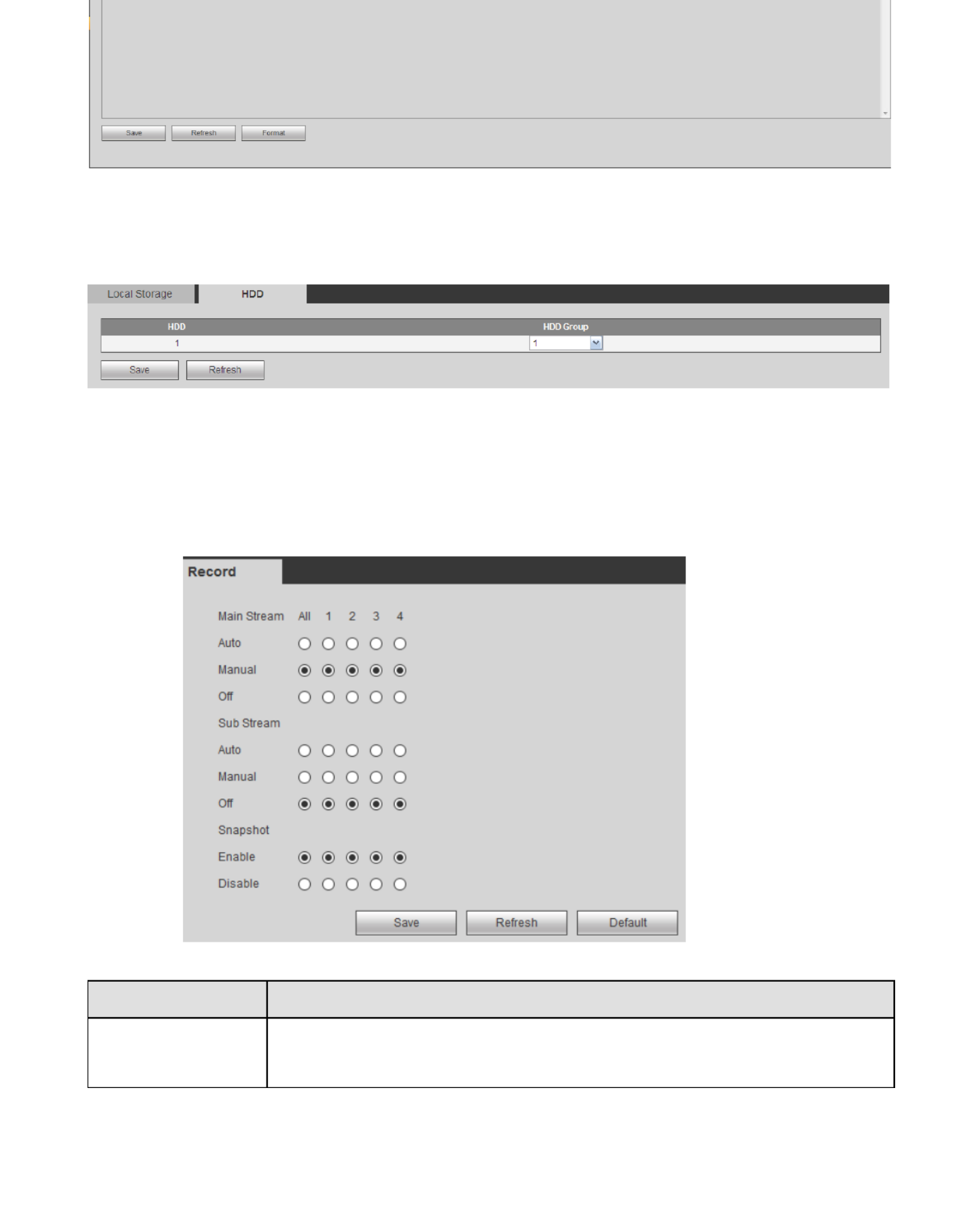
118
Figure 5- 53
5.8.4.2.2 HDD Setting
The HDD interface is to set HDD group. See Figure 5- . 54
Figure 5- 54
5.8.4.3 Record
Main Stream, Sub Stream & Snapshot
The main stream, sub stream & snapshot interface is shown as in Figure 5-55. Here you can
set corresponding HDD group to save main stream.
Figure 5- 55
Refer to the following sheet for detailed information.
Parameter
Function
Channel
Here you can view channel number.
The number displayed here is the max channel amount of your
device.
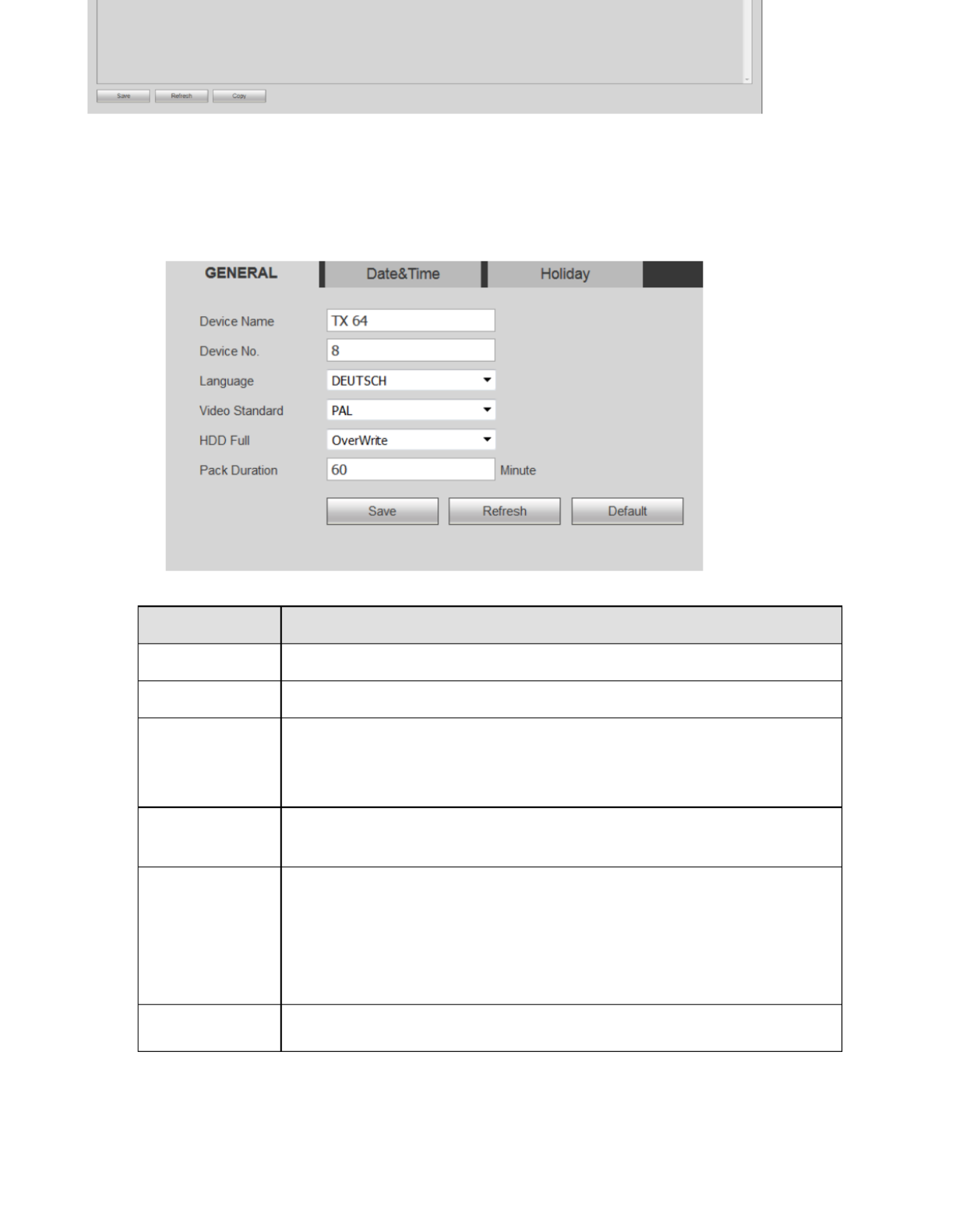
120
Figure 5- 58
5.8.5 Setting
5.8.5.1 General
The general interface includes general, date/time and holiday setup.
5.8.5.1.1 General
The general interface is shown as in Figure 5- 59.
Figure 5- 59
Refer to the following sheet for detailed information.
Parameter
Function
Device Name
It is to set device name.
Device No.
It is device channel number.
Language
You can select the language from the dropdown list.
Note the device needs to reboot to get the modification
activated.
Video
Standard
This is to display video standard such as PAL.
HDD full
Here is for you to select working mode when hard disk is full.
There are two options: stop recording or overwrite. If current
working HDD is overwritten or the current HDD is full while the
next HDD is no empty, then system stops recording, If the
current HDD is full and then next HDD is not empty, then
system overwrites the previous files.
Pack duration
Here is for you to specify record duration. The value ranges
from 1 to 120 minutes. Default value is 60 minutes.
5.8.5.1.2 Date and time

121
Figure 5- 60
Refer to the following sheet for detailed information.
Parameter
Function
Date format
Here you can select date format from the dropdown list.
Time Format
There are two options: 24-H and 12- H.
Date Separator
Select the date separator from the dropdown list.
Time zone
The time zone of the device.
System time
It is to set system time. It becomes valid after you set.
Sync PC
You can click this button to save the system time as your PC current
time.
DST
Here you can set day night save time begin time and end time. You
can set according to the date format or according to the week format.
NTP
You can check the box to enable NTP function.
NTP server
You can set the time server address.
Port
It is to set the time server port.
Interval
It is to set the sync periods between the device and the time server.
5.8.5.1.3 Holiday
Holiday setup interface is shown as in Figure 5- 61.
Here you can click Add holidays box to add a new holiday and then click Save button to
save.

122
Figure 5- 61
5.8.5.2 Account
Note:
For the character in the following user name or the user group name, system max
supports 6-digits. The space in the front or at the end of the string is null. The valid string
includes: character, number, and underline.
The user amount default setup is and the group amount default setup is . The 64 20
factory default setup includes two levels: user and admin. You can set the corresponding
group and then set the rights for the respective user in the specified groups.
User management adopts group/user modes. The user name and the group name shall
be 76.unique. One user shall be included in only one group. See Figure 5-
5.8.5.2.1 User
In this interface you can add/remove user and modify user name. See Figure 5-62.
Figure 5- 62
Add user: It is to add a name to group and set the user rights. See Figure 5- 63.
There are four default users: admin/888888 and hidden user ― ‖. Except user 6666default 66,
other users have administrator right. Hidden user ―default‖ is for system interior use only and
can not be deleted. When there is no login user, hidden user ―default‖ automatically login.
You can set some rights such as monitor for this user so that you can view some channel
view without login. Here you can input the user name and password and then select one
group for current user. : the user rights shall not exceed the group right setup. For Note
convenient setup, make sure the general user has the lower rights setup than the admin.

123
Figure 5- 63
Modify user
It is to modify the user property, belonging group, password and rights. See Figure 5- 64
Modify password
It is to modify the user password. You need to input the old password and then input the new
password twice to confirm the new setup. Click the OK button to save. : the password Note
ranges from 1-digit to 6-digit. It shall include the number only. For the user of the account
rights, he can modify the password of other users.
Figure 5- 64
5.8.5.2.2 Group
The group management interface can add/remove group, modify group password and etc.

124
Figure 5- 65
Add group: It is to add group and set its corresponding rights. See Figure 5- Input the 66
group name and then check the box to select the corresponding rights. It includes:
shutdown/reboot device, live view, record control, PTZ control and etc.
Figure 5- 66
Modify group
Click the modify group button, you can see an interface is shown as in Figure 5- Here you 67
can modify group information such as remarks and rights.

125
Figure 5- 67
5.8.5.3 Display
Display interface includes GUI, TV adjust, Tour and zero-channel encoding.
5.8.5.3.1 Display
Here you can set background color and transparency level See Figure 5-68. .
Figure 5- 68
Refer to the following sheet for detailed information.
Parameter
Function
Resolution
There are four options: 1920×1080, 1280×1024(default),
1280×720,1024×768. Note the system needs to reboot to activate
current setup.
Color Mode
Choose from he dropdown menu, standard, bright, soft or Colorful.
Transparency
Here is for you to adjust transparency. The value ranges from 128
to 255.
Time Display/
Channel
Display
Check the box here, you can view system time and channel
number on the monitor video.
Image enhance
Check the box; you can optimize the margin of the preview video.

126
motion detect tour and alarm tour mode.
Figure 5- 69
Refer to the following sheet for detailed information.
Parameter
Function
Enable tour
Check the box here to enable tour function.
Interval
Here is for you to adjust transparency. The value ranges
from 5 to 120s. The default setup is 5s.
Split
Here you can set window mode and channel group. System
can support 1/4-window according to device channel
amount.
Motion tour/
Alarm tour
Here you can set motion detect tour/alarm tour window
mode. System supports 1/4-window now.
5.8.5.4 Default
The default setup interface is shown as in Figure 5- Here you can select 70.
Network/Event/Storage/Setting/Camera. Or you can check the All box to select all items.
Figure 5- 70
5.8.5.5 Import/Export
The interface is shown as in Figure 5-71. This interface is for you to export or import the
configuration files.

127
Figure 5- 71
Refer to the following sheet for detailed information.
Parameter
Function
Browse
Click to select import file.
Import
It is to import the local setup files to the system.
Export
It is to export the corresponding WEB setup to your local
PC.
5.8.5.6 Auto maintain
The auto maintains interface is shown as in Figure 5- Here you can select auto reboot 72.
and auto delete old files interval from the dropdown list. If you want to use the auto delete old
files function, you need to set the file period. Click Manual reboot button, you can restart
device manually.
Figure 5- 72
5.8.5.7 Upgrade
The upgrade interface is shown as in Figure 5- . Select the upgrade file and then click the 73
update button to begin update. Note the file name shall be as *.bin. During the upgrade
process, do not unplug the power cable, network cable, or shutdown the device.
Important
Improper upgrade program may result in device mal function! Make sure the
operation is operated under the supervision of the professional engineer!
Figure 5- 73

128
The version interface is shown as in Figure 5- 74_1
Here you can view record channel, alarm input/output
information, software version, release date and etc. Note
the following information is for reference only.
Figure 5- 74_1
5.9.2 Log
Here you can view system log. See Figure 5- 74
Figure 5- 74
Refer to the following sheet for log parameter information.
Parameter
Function
Type
Log types include: all, system operation, configuration operation, data
operation, event operation, record operation, user management, log
clear, playback and connection.
Start time
Set the start time of the requested log.
End time
Set the end time of the requested log.
Search
You can select log type from the drop down list and then click search
button to view the list.
You can click the stop button to terminate current search operation.
Detailed
information
You can select one item to view the detailed information.
Clear
You can click this button to delete all displayed log files. Note system
does not support clear by type.
Backup
You can click this button to backup log files to current P C.
Termékspecifikációk
| Márka: | Technaxx |
| Kategória: | VCR |
| Modell: | Security PRO TX-64 |
Szüksége van segítségre?
Ha segítségre van szüksége Technaxx Security PRO TX-64, tegyen fel kérdést alább, és más felhasználók válaszolnak Önnek
Útmutatók VCR Technaxx

29 Július 2024
Útmutatók VCR
- VCR Samsung
- VCR Sony
- VCR LG
- VCR Grundig
- VCR Philips
- VCR Reolink
- VCR Bosch
- VCR Panasonic
- VCR Canon
- VCR JVC
- VCR Toshiba
- VCR Ubiquiti Networks
- VCR TP-Link
- VCR Motorola
- VCR Digitus
- VCR TRENDnet
- VCR EZVIZ
- VCR Aiwa
- VCR Speco Technologies
- VCR Blackmagic Design
- VCR Hikvision
- VCR Zoom
- VCR Synology
- VCR Navitel
- VCR Hitachi
- VCR Dahua Technology
- VCR Planet
- VCR Ernitec
- VCR Tenda
- VCR Daewoo
- VCR Foscam
- VCR Imou
- VCR Grandstream
- VCR D-Link
- VCR Milesight
- VCR Monacor
- VCR Blaupunkt
- VCR Moxa
- VCR Abus
- VCR Vivotek
- VCR AVer
- VCR DataVideo
- VCR QNAP
- VCR Dual
- VCR Provision-ISR
- VCR Axis
- VCR ACTi
- VCR Airlive
- VCR Sylvania
- VCR Magnum
- VCR GeoVision
- VCR LevelOne
- VCR Seagate
- VCR Kunft
- VCR Digital Watchdog
- VCR DirecTV
- VCR Skytronic
- VCR Hanwha
- VCR Magnavox
- VCR Inkovideo
- VCR Pentatech
- VCR Bang Olufsen
- VCR HiLook
- VCR Mach Power
- VCR Avigilon
Legújabb útmutatók VCR

7 Április 2025
6 Április 2025
5 Április 2025

4 Április 2025

15 Január 2025
12 Január 2025

31 December 2025
31 December 2025
31 December 2025
22 December 2024