Használati útmutató RTS DBP
RTS
Intercomsysteem
DBP
Olvassa el alább 📖 a magyar nyelvű használati útmutatót RTS DBP (98 oldal) a Intercomsysteem kategóriában. Ezt az útmutatót 7 ember találta hasznosnak és 2 felhasználó értékelte átlagosan 4.5 csillagra
Oldal 1/98

DBP Digital Beltpack
DBP 4M | DBP 4F | DBP 5F
en Technical Manual


DBP Digital Beltpack Table of contents | en 3
Bosch Security Systems, LLC Technical Manual 2021-06 | 01 | F.01U.380.825
Table of contents
1
Safety
Safety
Safety
SafetySafety 6
6
6
66
1.1 6Copyright and Disclaimer
1.2 6Notices
1.3 7Important safety instructions
2
Introduction
Introduction
Introduction
IntroductionIntroduction 8
8
8
88
2.1 8Features
3
Reference view
Reference view
Reference view
Reference viewReference view 9
9
9
99
3.1 10Belt clip removal and replacement
4
Cabling
Cabling
Cabling
CablingCabling 11
11
11
1111
4.1 11To OMS
4.2 12To OMI
4.3 12To ODIN
4.4 13PoE
5
Install the Bluetooth dongle
Install the Bluetooth dongle
Install the Bluetooth dongle
Install the Bluetooth dongleInstall the Bluetooth dongle 15
15
15
1515
6
Create an Intercom connection
Create an Intercom connection
Create an Intercom connection
Create an Intercom connectionCreate an Intercom connection 16
16
16
1616
6.1 16Connect to OMS using Connect Devices
6.2 16Configure intercom OMNEO ports to make connection offers
6.2.1 16Configure OMS to make a connection offer
6.2.2 17Configure ODIN to make a connection offer
6.3 18Accept a connection offer on DBP
6.4 18Create connections using IPedit
6.4.1 18Add DBP to IPedit
6.4.2 19Configure an OMNEO channel for DBP using IPedit
6.4.3 21Configure the DBP to accept an OMNEO offer using IPedit
6.5 22Create connections using AZedit
6.5.1 22Configure OMS/ODIN to make a connection offer
6.5.2 23Configure an OMI card to make a connection offer
7
Modes of operation
Modes of operation
Modes of operation
Modes of operationModes of operation 25
25
25
2525
7.1 25PL Mode
7.2 25Keypanel Mode
8
Basic Operation
Basic Operation
Basic Operation
Basic OperationBasic Operation 26
26
26
2626
8.1 26Main screen icons
8.2 27Navigation basics
8.3 28Hot keys
8.4 31UI controls
8.5 32Volume adjustment
8.6 34Call Signaling (PL Mode only)
8.7 34Talk and Listen
8.8 35Call waiting window
8.9 37Bluetooth
8.9.1 37Answer a phone call via Bluetooth
8.9.2 39Phone call management window
8.9.3 39Patch a phone call to the Intercom
8.10 40Upgrade firmware
8.11 44Download screen saver images or splash screen images
9
Menu Structure
Menu Structure
Menu Structure
Menu StructureMenu Structure 46
46
46
4646
9.1 46Setup | Network
9.1.1 47Device Name

4en | Table of contents DBP Digital Beltpack
2021-06 | 01 | F.01U.380.825 Technical Manual Bosch Security Systems, LLC
9.1.2 48DHCP
9.1.3 48IP Address
9.1.4 49Netmask
9.1.5 50Gateway
9.1.6 51DNS Server
9.1.7 52Domain
9.1.8 53MAC Address
9.2 53Setup | Offers
9.2.1 53DBP Offers
9.2.2 54Aux Offers
9.3 54Setup | Key Assignments
9.4 56Setup | Service
9.4.1 56Tone
9.4.2 57Test Mode
9.4.3 58User Reset
9.4.4 59Factory Reset
9.5 61Setup | Authentication
9.5.1 61Require PIN
9.5.2 62Set PIN
9.6 63Setup | Key Modes
9.7 63Audio | Headset
9.7.1 63Sidetone
9.7.2 64Echo Canceller
9.8 65Audio | Microphone
9.8.1 65Mic Select
9.8.2 65Mic Gain
9.8.3 66Hot Mic
9.8.4 67Noise Gate
9.8.5 68XLR Mic Type
9.8.6 68Allow Mic Kill
9.8.7 69Send Mic Kill
9.9 70Audio | 3.5mm Aux
9.9.1 70Aux Mode
9.9.2 71Input Gain
9.9.3 71Output Gain
9.10 72Audio | BT Aux Levels
9.10.1 72Input Gain
9.10.2 72Output Gain
9.11 73Audio | OMNEO CH 2 Levels
9.11.1 73Input Gain
9.11.2 74Output Gain
9.12 74Audio | Mixer
9.12.1 74Headset L+R
9.12.2 75Headset Left
9.12.3 76Headset Right
9.12.4 76To Intercom
9.12.5 773.5mm Aux Out
9.12.6 77OMNEO Ch2 Out
9.12.7 78Bluetooth Out

DBP Digital Beltpack Table of contents | en 5
Bosch Security Systems, LLC Technical Manual 2021-06 | 01 | F.01U.380.825
9.13 79Call Alerts
9.13.1 79Call Beep
9.13.2 80Call Vibration
9.14 80Information
9.15 81Bluetooth
9.15.1 81Ready to Pair
9.15.2 83Paired Headsets
9.15.3 84Paired Aux Devs
9.16 86Display
9.16.1 86Display Mode
9.16.2 87Brightness
9.16.3 88Screen Saver
9.16.4 88Screen Flip
10
Icons
Icons
Icons
IconsIcons 90
90
90
9090
11
Technical data
Technical data
Technical data
Technical dataTechnical data 93
93
93
9393

6en | Safety DBP Digital Beltpack
2021-06 | 01 | F.01U.380.825 Technical Manual Bosch Security Systems, LLC
1 Safety
1.1 Copyright and Disclaimer
All rights reserved. The product information and design disclosed herein were originated by
and are the property of Bosch Security Systems, LLC. Bosch reserves all patent, proprietary
design, manufacturing, reproduction, use and sales rights thereto, and to any article disclosed
therein, except to the extent rights are expressly granted to others.
No part of this document may be reproduced or transmitted in any form by any means,
electronic, mechanical, photocopying, recording, or otherwise, without the prior written
permission of the publisher. For information on getting permission for reprints and excerpts,
contact Bosch Security Systems, LLC.
All other trademarks are property of their respective owners.
The content and illustrations are subject to change without prior notice.
1.2 Notices
CE Compliant and UL Certified
The lightning flash and
arrowhead within the triangle
is a warning sign alerting you
of dangerous voltage inside
the product.
Caution: To reduce the risk of
electric shock, do not remove
cover. No user-serviceable
parts inside. Refer servicing
to qualified service personnel
The exclamation point within
the triangle is a warning sign
alerting you of important
instructions accompanying
the product.
See marking on bottom/back of product.
!
Warning!
Apparatus shall not be exposed to dripping or splashing and no objects filled with liquids,
such as vases, shall be placed on the apparatus.
!
Warning!
This is a CLASS A product. In a domestic environment, this product may cause radio
interference, in which case the user may be required to take adequate measures.

DBP Digital Beltpack Safety | en 7
Bosch Security Systems, LLC Technical Manual 2021-06 | 01 | F.01U.380.825
!
Warning!
To reduce the risk of fire or electric shock, do not expose this apparatus to rain or moisture.
1.3 Important safety instructions
1. Read these instructions.
2. Keep these instructions.
3. Heed all warnings.
4. Follow all instructions.
5. Do not use this apparatus near water.
6. Clean only with a dry cloth.
7. Do not install near any heat sources such as radiators, heat registers, stoves, or other
apparatus (including amplifiers) that produce heat.
8. Only use attachments/accessories specified by the manufacturer.
9. Use only with the cart, stand, tripod, bracket, or table specified by the manufacturer, or
with the apparatus. When a cart is used, use caution when moving the cart/apparatus
combination to avoid injury from tip-over.
10. Unplug the apparatus during lightning storms or when unused for long periods of time.
11. Refer all servicing to qualified service personnel. Servicing is required when the
apparatus has been damaged in any way, such as power-supply cord or plug is damaged,
liquid has been spilled or objects have fallen into the apparatus, the apparatus has been
exposed to rain or moisture, does not operate normally, or has been dropped.

8en | Introduction DBP Digital Beltpack
2021-06 | 01 | F.01U.380.825 Technical Manual Bosch Security Systems, LLC
2 Introduction
The (Digital Belt Pack) is one of RTS' initial offerings in the wired digital party lineDBP
solution space. The DBP provides two modes in which the DBP can operate for up to four
configurable audio conferences. There are two modes DBP can operate, (Keypanel) modeKP
and (Party Line) mode. When connected to an intercom in KP mode, any key assignmentPL
that is made to a keypanel can be made on the DBP. When connected to an OMS, the
assignment types are limited to PL, (relays), and (UPL resources).RY UR
When connected to the (OMNEO Main Station), the DBP operates as a digital party lineOMS
device. The DBP also connects to any of the RTS matrix products directly via OMNEO. This
includes OMI cards in ADAM (or ADAM -M) frames or OMNEO ports on ODIN frames. When
connected to an RTS OMNEO matrix, the DBP acts as a wired, 4-button keypanel. The DBP
automatically determines the correct mode of operation (digital party line connection to OMS
or keypanel connection to the matrix) at power on.
The DBP recovers power over an 802.3af or 802.3at compliant Ethernet interface. The PoE
(power over Ethernet) In port connects to a PoE compliant power sourcing equipment. The
PoE Out port is available for daisy chain connections to other DBPs.
The DBP comes in a rugged, over-molded enclosure that is IP-53 compliant. It has a full-color
TFT display and an icon-based menu interface, which allows for local configuration of essential
customer preferences.
2.1 Features
– Incorporates both XLR and 3.5 mm TRRS connectors for headsets, and the XLR headsets
are available in 3 different headset XLR options: 4-pin female, 4-pin male, and 5-pin
female. The 5-pin female headset supports stereo audio.
– PoE powered via an 802.3af or 802.3at managed switch or PoE injector. Contains a PoE
In and PoE Out port, which allows up to six DBPs to be daisy-chain connected to the
same PoE (+) switch port.
– DBP connects to an OMNEO main station (Digital Party Line) or an OMNEO capable
matrix (OMI card or ODIN). DBP can support up to four active Party Lines. 40 DBPs can
be connected to OMS (based on model), 64 DBPs can be connected to one OMI card
(based on model, 128 DBPs can be connected to one ODIN, based on model).
– Supports Bluetooth audio connectivity using either an IO Gear GBU522 dongle or an LM
Technologies LM506 dongle.
– Incoming CALL notifications via audible alerts or haptic vibration.

DBP Digital Beltpack Reference view | en 9
Bosch Security Systems, LLC Technical Manual 2021-06 | 01 | F.01U.380.825
3 Reference view
1 2 3 4 5 67
7
8
910 11 12
13 14
1 Master Volume Control knob / Key A and C Volume knob
2 CLR/BACK button
3 CALL button
4 SEL/MENU button
5 Master Volume Control knob / Key B and D Volume knob
6 Lanyard loop
7 Belt Clip
8 USB Bluetooth dongle connector
9 PoE Out connector
10 PoE In connector
11 XLR Headset connector
12 3.5mm AUX connector
13 Talk keys (A, B, C, and D)
14 Display screen

10 en | Reference view DBP Digital Beltpack
2021-06 | 01 | F.01U.380.825 Technical Manual Bosch Security Systems, LLC
3.1 Belt clip removal and replacement
1
2
To , do the following:remove the belt clip
1. Lift the tension clip (1) up.
2. With the tension clip up, slide the (2).belt clip out of the belt clip track
To , do the following:replace the belt clip
4Align and slide the belt clip into the belt clip track (2).
A click is felt/heard when the belt clip is securely in place.

DBP Digital Beltpack Cabling | en 11
Bosch Security Systems, LLC Technical Manual 2021-06 | 01 | F.01U.380.825
4 Cabling
4.1 To OMS
i
Notice!
PoE is not necessary as long as it is on a network that can reach the DBP.
To , do the following:cable the DBP to an OMS main station
1. Using a CAT-5e cable, attach on the DBP.one end to the PoE IN connector
2. Connect the to an approved PoE switch.other end of the cable
3. Using a second CAT-5e cable, connect .one end to the approved PoE switch
4. Connect the on the OMS device.other end to the OMNEO connector
PoE Switch
i
Notice!
If using IPedit to configure the connection between the DBP and the OMS, a third cable is
needed to connect the OMNEO port to the PoE switch.

12 en | Cabling DBP Digital Beltpack
2021-06 | 01 | F.01U.380.825 Technical Manual Bosch Security Systems, LLC
For information on connecting the DBP to the OMS, see
Configure OMS to make a connection
offer, page 16
.
4.2 To OMI
To , do the following:cable a DBP to an OMI card
1. Using a CAT-5e cable, attach on the DBP.one end to the PoE IN connector
2. Connect the to an approved PoE switch.other end of the cable
3. Using a second CAT-5e cable, connect .one end to the approved PoE switch
4. Connect the other end to an Ethernet connector on the OMI card.
SERIAL
J5
J2J1
ETHERNET
OMI-2 BC
J3
J4
PoE Switch
For information on connecting the DBP to the OMI card, see
Configure an OMI card to make a
connection offer, page 23
.
4.3 To ODIN
To , do the following:connect the DBP to an ODIN matrix
1. Using a CAT-5e cable, attach on the DBP.one end to the PoE IN connector
2. Connect the to an approved PoE switch.other end of the cable

DBP Digital Beltpack Cabling | en 13
Bosch Security Systems, LLC Technical Manual 2021-06 | 01 | F.01U.380.825
3. Using a second CAT-5e cable, connect .one end to the approved PoE switch
4. Connect on ODIN.the other end to the OMNEO port
J6 J7
PoE Switch
i
Notice!
If using IPedit to configure the connection between the DBP and ODIN, use a third cable to
connect the OMNEO port to the PoE switch.
For information on how to connect the DBP to an ODIN, refer to
Configure ODIN to make a
connection offer, page 17
.
4.4 PoE
The Digital Belt Pack includes a PoE In and PoE Out connector that allows multiple DBPs to be
daisy chained from the same switch port. RTS recommends use of an 802.3at compliant PoE
switch for daisy chaining. RTS guidance on the number of DBPs that can be daisy chained
from an 802.3at port are as follows:
– Using CAT-5e cable or better, up to six DBPs can be daisy chained where each daisy chain
span has a length of 100 foot (30 m) or less (total of 600 feet / 180 meters of cable).
– Using CAT-5e cable or better, up to three DBPs can be daisy chained where each daisy
chain span has a length of 328 foot (100 m) or less (total of 984 feet / 300 meters of
cable).

14 en | Cabling DBP Digital Beltpack
2021-06 | 01 | F.01U.380.825 Technical Manual Bosch Security Systems, LLC
i
Notice!
It is possible to use PoE injectors on the end of a daisy chain to extend the number of DBPs
and cable lengths supported
Using more than 6 DBPs on the same 802.3at switch port may result in unreliable beltpack
operation.
To , do the following:daisy chain belt backs together
1. Connect one end of a CAT-5e cable from the .PoE Out connector on one DBP belt pack
2. Connect the other end of the CAT-5e cable to the PoE In connector on a second DBP
belt pack.
3. Connect one end of a second CAT-5e cable to the PoE Out connector on the second DBP
belt pack.
4. Connect the other end of the second CAT-5e cable to the PoE In connector on a third
DBP belt pack.
5. Repeat these to add additional belt packs to the daisy chain.steps
J2
J3
Figure4.1: Daisy Chain Example

DBP Digital Beltpack Install the Bluetooth dongle | en 15
Bosch Security Systems, LLC Technical Manual 2021-06 | 01 | F.01U.380.825
5 Install the Bluetooth dongle
It is best to install the dongle when there is no power to the device. If you install the dongle
while the DBP is on, the belt pack recognizes the dongle and reboots to initialize the hardware
properly. If you remove the dongle while the DBP has power, it does not reboot.
i
Notice!
Optimal Bluetooth audio quality is achieved when the DBP is paired with a headset that
incorporates a boom microphone construction versus Bluetooth headsets with embedded
microphones (i.e., ear buds).
To , do the following:install the Bluetooth dongle
1. Open the (1).USB connector door
Take care not to over-extend the door.
2. Insert the (2) in the connector.dongle
Figure5.1: DBP USB dongle installation
3. Close the (1).USB connector door
4. Push the to ensure the door is within the DBP enclosure.door surface

16 en | Create an Intercom connection DBP Digital Beltpack
2021-06 | 01 | F.01U.380.825 Technical Manual Bosch Security Systems, LLC
6 Create an Intercom connection
6.1 Connect to OMS using Connect Devices
To , do the following:connect OMNEO devices via the OMS front panel UI
1. Navigate to (Connect Devices menu itemmenu item Configuration | Ports | Connect
Devices).
2. Click the .ENC2 encoder knob
OMS scans for available OMNEO devices, and then shows devices that support Easy
Connect (KP-Series, DBP, OKI, etc.). Discoverable devices need to be powered on,
connected to the network, and be on the same subnet.
3. Navigate to the .Connect All button
OR
Navigate to the .OMNEO device
4. Select the .Connect button
6.2 Configure intercom OMNEO ports to make connection offers
6.2.1 Configure OMS to make a connection offer
i
Notice!
For more information, see the OMS manual found at www.rtsintercoms.com.
To , do the following:connect a DBP to OMS
1. Navigate to the OMNEO icon (Configuration | Ports | OMNEO).
2. Click the .ENC2 encoder knob
The OMNEO Channels screen displays.
3. Select the .port to configure

DBP Digital Beltpack Create an Intercom connection | en 17
Bosch Security Systems, LLC Technical Manual 2021-06 | 01 | F.01U.380.825
i
Notice!
If you are connecting a DBP or Keypanel in order to power it up on this port, choose Channel
1. Any other port is an Aux port and the DBP has only two channels.
1. Enter the of the partner device to connect to this port.device name
2. Select the of partner device.type
3. Select the on the partner device to connect to.channel number
4. (Optional) Change the for the connection.Rx Latency
The default is recommended.
5. When finished, press to exit.ENC1
6. Choose to save the changes.Save
6.2.2 Configure ODIN to make a connection offer
i
Notice!
For more information, see the ODIN manual found at www.rtsintercoms.com
To , do the following:connect a DBP to an ODIN
1. Navigate to the .OMNEO icon
2. Click the .right encoder knob
The OMNEO Channels screen displays.
i
Notice!
If the intercom system contains only one ODIN frame, the Frame field is not displayed. If the
intercom system contains multiple ODIN frames, the Frame field activates and allows ports in
other frames to be selected and configured. While the Frame field is highlighted, press the
right encoder knob to activate the field. Once activated, turn the right encoder knob to select
another frame in the system.
3. Navigate to the .Port field
4. Click the .right encoder knob
The Port field becomes active.
5. Scroll to the .desired port
6. Navigate to the .Device Name field
7. Enter the to connect to this port.device name of the partner device
8. Navigate to the .Device Type field
9. Scroll to the of the partner device.OMNEO device type
10. Navigate to the .channel field
11. Scroll to the on the partner device.desired channel
12. (Optional) Enter a for this connection.description
18 en | Create an Intercom connection DBP Digital Beltpack
2021-06 | 01 | F.01U.380.825 Technical Manual Bosch Security Systems, LLC
13. (Optional) Select the to use for this connection. (1 ms is recommended for bestlatency
quality).
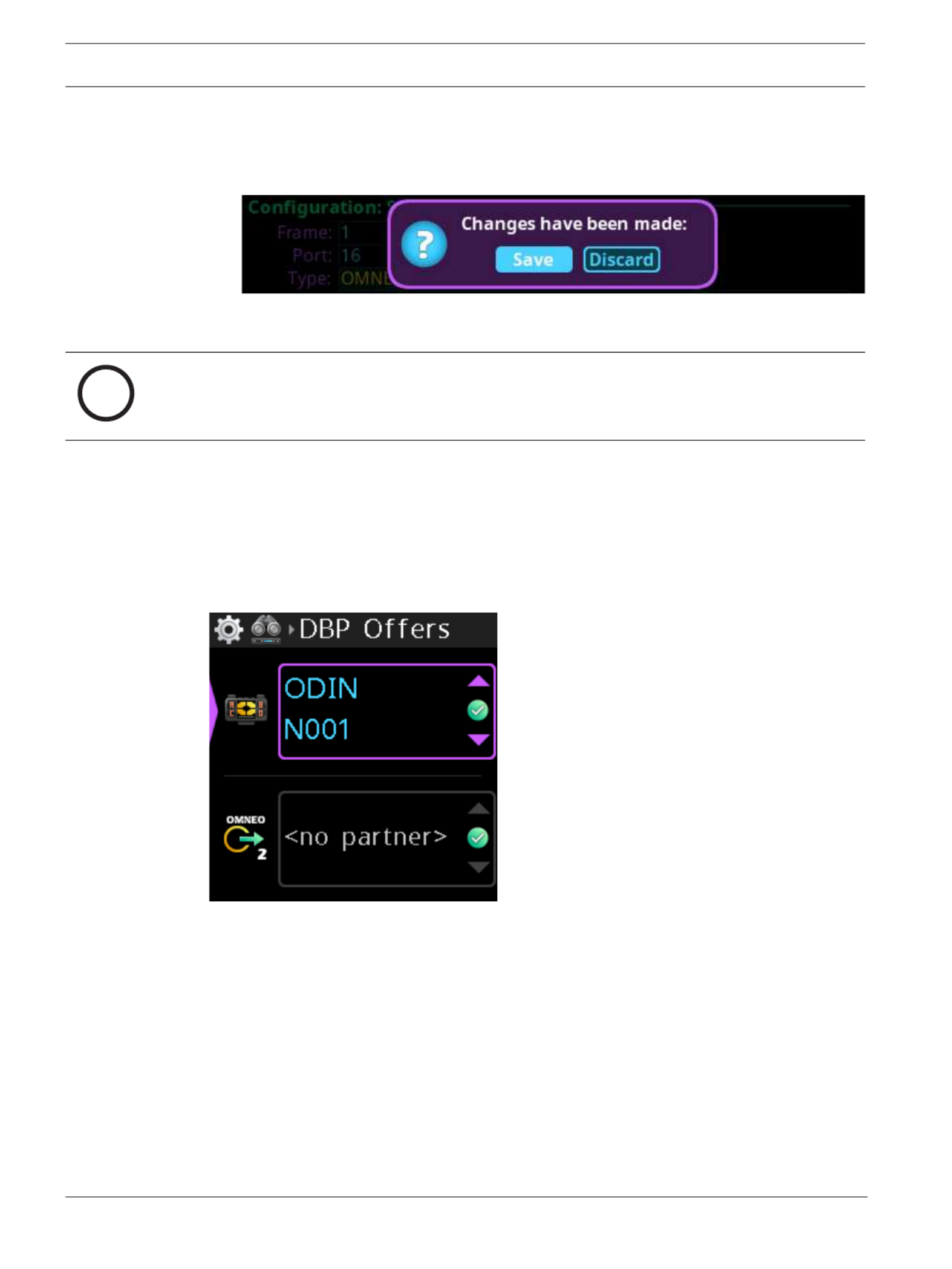
14. Click the to exit the screen.left encoder knob
A Changes Made confirmation message displays.
15. Navigate to the .desired action
16. Click the right encoder knob to .confirm
i
Notice!
Alternately, the left shaft encoder can be clicked or the CLR button can be pressed to cancel
this prompt and go back to editing the underlying screen.
17. Click the right encoder knob to .confirm the selection
6.3 Accept a connection offer on DBP
To , do the following:accept a DBP Offer
1. Navigate to (Setup | Offers | DBP Offers).the DBP Offers menu item
2. Press the .SEL/MENU button
The field highlights.
3. Rotate either to scroll through the available offers.shaft encoder
4. Press the to confirm the change, or press the toSEL/MENU button CLR/BACK button
abort changes.
6.4 Create connections using IPedit
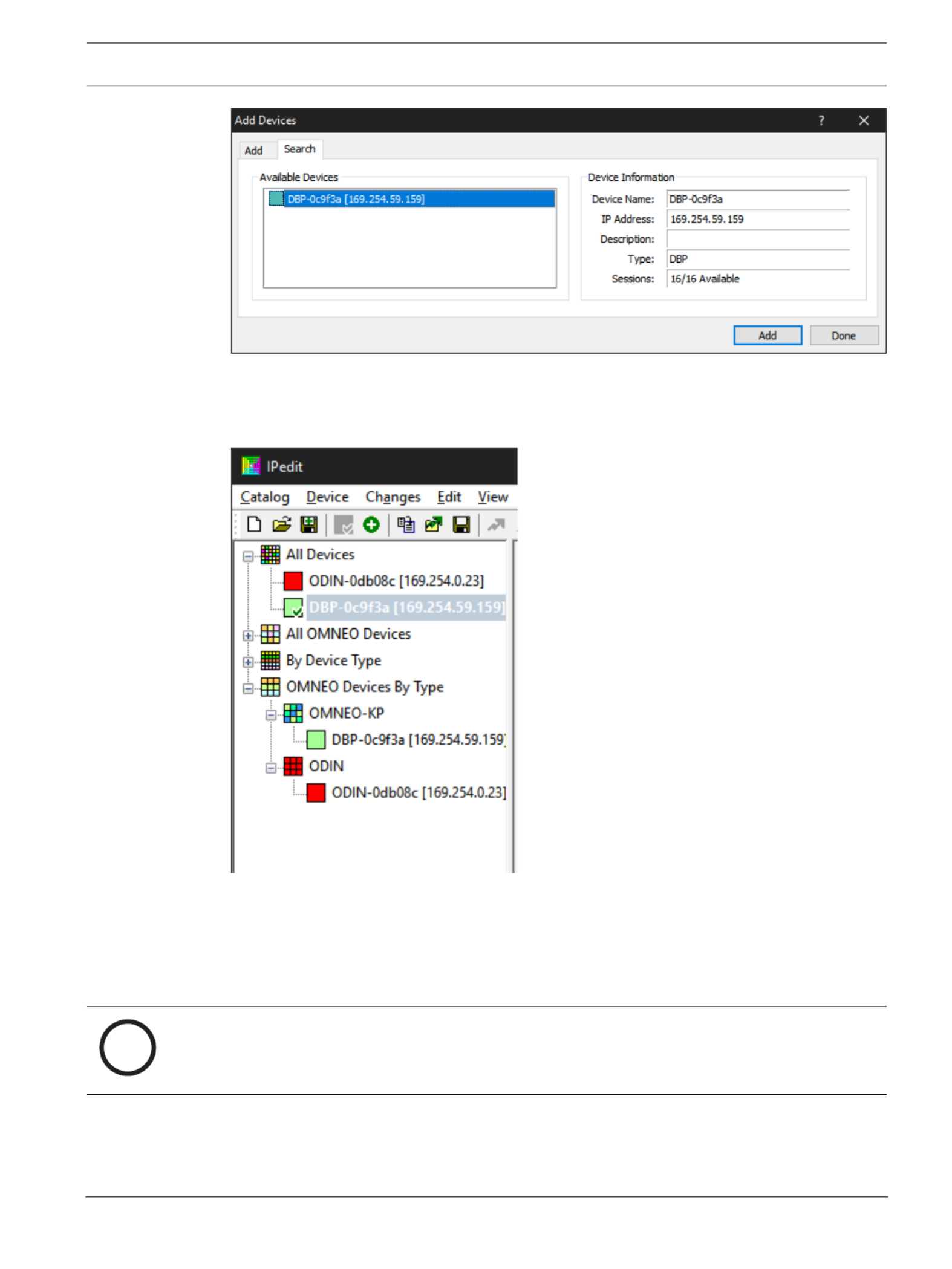
6.4.1 Add DBP to IPedit
To , do the following:add a DBP to IPedit
1. Open .IPedit
2. Select .Add from the Device menu
The Add Devices screen displays.
DBP Digital Beltpack Create an Intercom connection | en 19
Bosch Security Systems, LLC Technical Manual 2021-06 | 01 | F.01U.380.825
3. Select .one or more available devices
The Add button becomes active.
4. Click the .Add button
The device catalog displays the selected devices.
5. Click the .Done button
The screen closes.
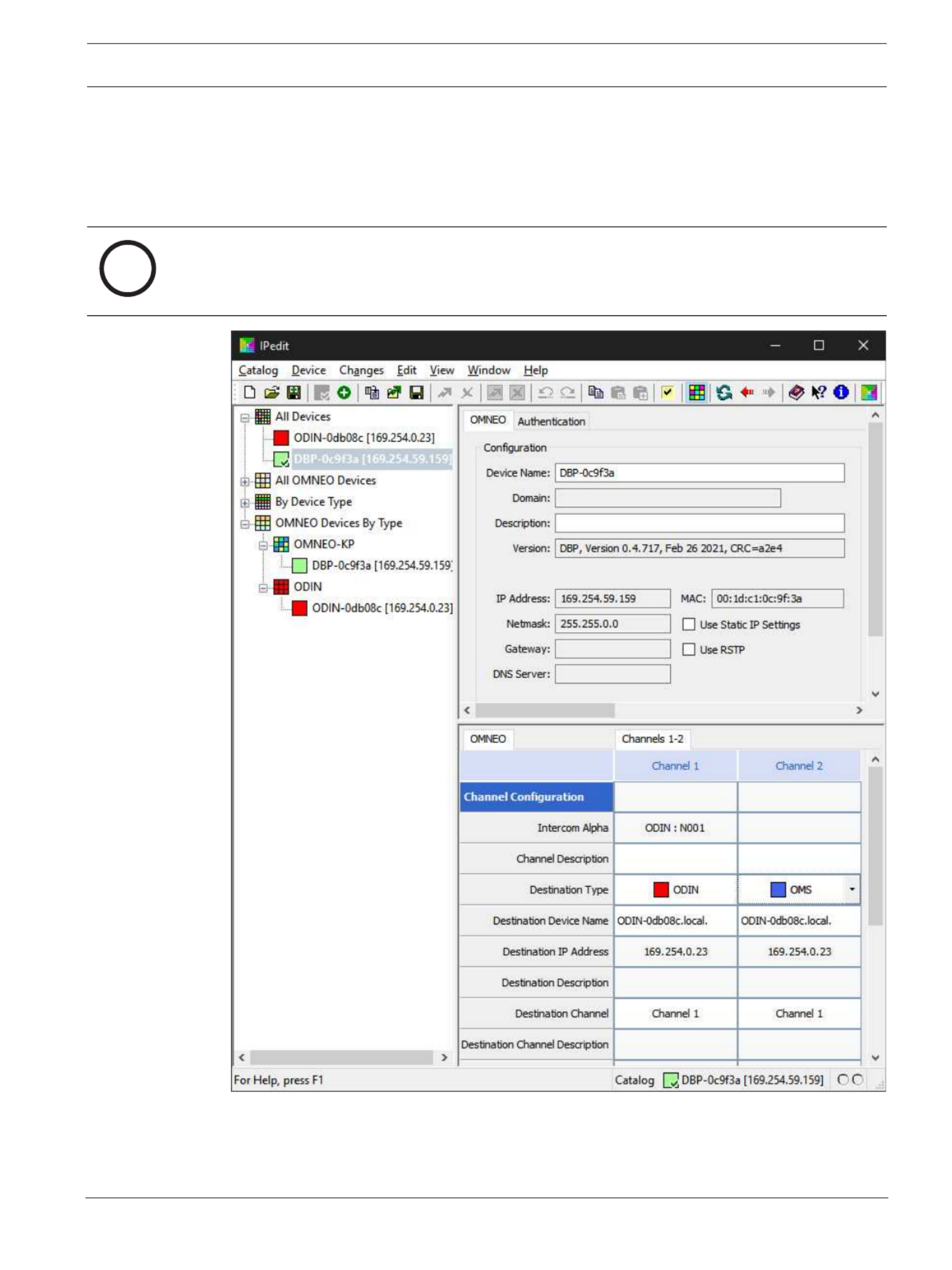
6.4.2 Configure an OMNEO channel for DBP using IPedit
To , do the following:configure an OMNEO channel for DBP using IPedit
i
Notice!
The Destination Type does not need to be selected if using the Browse window to select the
device. It fills the type and IP Address automatically.
Using the Channel Configuration Pane

20 en | Create an Intercom connection DBP Digital Beltpack
2021-06 | 01 | F.01U.380.825 Technical Manual Bosch Security Systems, LLC
1. In the Destination Device Name field, click the … . button
The Discovered Devices screen displays.
2. Expand the to view the destination devices available.tree
3. Select the for the destination.desired device
4. Click .OK
The screen closes.
5. Select the to which the device connects.channel
6. (Optional) Enter the .channel description
DBP Digital Beltpack Create an Intercom connection | en 21
Bosch Security Systems, LLC Technical Manual 2021-06 | 01 | F.01U.380.825
6.4.3 Configure the DBP to accept an OMNEO offer using IPedit
As an alternative to accepting offers through the DBP user interface, use IPedit to configure
the DBP to accept connection offers from ODIN. For information on using the DBP user
interface to accept connection offers, refer to
Accept a connection offer on DBP, page 18
.
To , do the following:configure the DBP to accept an OMNEO offer using IPedit
i
Notice!
The Destination Type does not need to be selected if using the Browse window to select the
device. It fills the type and IP Address automatically.
Using the Channel Configuration Pane
1. In the Destination Device Name field, click the … . button
The Discovered Devices screen displays.

22 en | Create an Intercom connection DBP Digital Beltpack
2021-06 | 01 | F.01U.380.825 Technical Manual Bosch Security Systems, LLC
2. Expand the to view the destination devices available.tree
3. Select the for the destination.desired device
4. Click .OK
The screen closes.
5. Select the to which the device connects.channel
i
Notice!
Be sure to configure the DBP channel to the configured ODIN channel. For example, if ODIN
channel 5 is configured for DBP channel 1, then DBP channel 1 should be configured to ODIN
channel 5.
6. (Optional) Enter the .channel description
Using the Device Configuration Pane
1. (Optional) Enter a for the device.description
2. Send the to the device.changes
6.5 Create connections using AZedit
6.5.1 Configure OMS/ODIN to make a connection offer
Ethernet configuration must be done before an OMNEO channel connection is made.
To , do the following:configure an OMS/ODIN to make a connection offer
1. On the KP screen, select the to configure the connection.port (2)
i
Notice!
If configuring OMS to make connections, you must select an OMNEO port from the Port Alpha
fields (2).
2. Click the .Edit button (1)
The Keypanel/Port Configuration screen opens.

DBP Digital Beltpack Create an Intercom connection | en 23
Bosch Security Systems, LLC Technical Manual 2021-06 | 01 | F.01U.380.825
3. Enter the of the device to which you want to connect. Use the browseDevice Name
button to open the available devices screen to select a device.
The IP Address of the device automatically populates the IP Address field.
4. Select the to which you want to connect.Device Type
5. Select the on which to communicate.OMNEO channel
6. Select the of the connection.Latency
i
Notice!
DBP supports a minimum latency of 2ms.
6.5.2 Configure an OMI card to make a connection offer
To , do the following:configure an OMI card to make a connection offer
1. From the status menu in AZedit, select .I/O Cards
The I/O Card Status screen appears showing a list of installed cards.
2. Right-click the desired .OMI card
3. Select .OMNEO Configuration
The OMNEO Configuration screen appears.

24 en | Create an Intercom connection DBP Digital Beltpack
2021-06 | 01 | F.01U.380.825 Technical Manual Bosch Security Systems, LLC
4. From the Local Channel drop down menu, select the to use to communicatechannel
across the network.
i
Notice!
Available channels appear with an asterisk next to them.
5. Enter the to which you want to make a connection.name of the device
OR
Select the to select from a list of devices.Browse button
6. Enter the to which you want to make a connection offer. IP address of the device
This field auto-populates when you select the device name.
7. From the Partner Device Type drop down menu, select the to which thetype of device
OMI card connects. This field auto-populates when you select the device name.
8. From the Partner Channel drop down menu, select the on the partner device tochannel
which you want to make a connection offer.
9. Click .Apply
Apply sends the changes to each of the cards for which you have made changes.
OR
Click to discard all changes.Cancel

DBP Digital Beltpack Modes of operation | en 25
Bosch Security Systems, LLC Technical Manual 2021-06 | 01 | F.01U.380.825
7 Modes of operation
DBP has two modes of operation, PL (Party Line) mode and Keypanel mode. When the belt
pack connects to an OMS, it runs in PL mode. When it connects to an ODIN or an OMI card in
an ADAM or ADAM M frame, it runs in Keypanel mode.
7.1 PL Mode
The DBP operates in PL mode when it connects to an OMS system. In PL mode, the display
screen shows Party Line assignments, Relay, or UPL Resource assignments. You can make PL
assignments via DBP, while you use AZedit to make Relay or UPL Resource assignments.
Figure7.1: Party Line Mode
To change PL assignments, refer to
Setup | Key Assignments, page 54
.
7.2 Keypanel Mode
The DBP operates in keypanel mode when it connects to an ODIN or an OMI card in an ADAM
or ADAM-M frame. In keypanel mode, the DBP supports any key assignment type supported by
the intercom.
Figure7.2: Keypanel Mode
To change key assignments in keypanel mode, refer to
Setup | Key Assignments, page 54
.

26 en | Basic Operation DBP Digital Beltpack
2021-06 | 01 | F.01U.380.825 Technical Manual Bosch Security Systems, LLC
8 Basic Operation
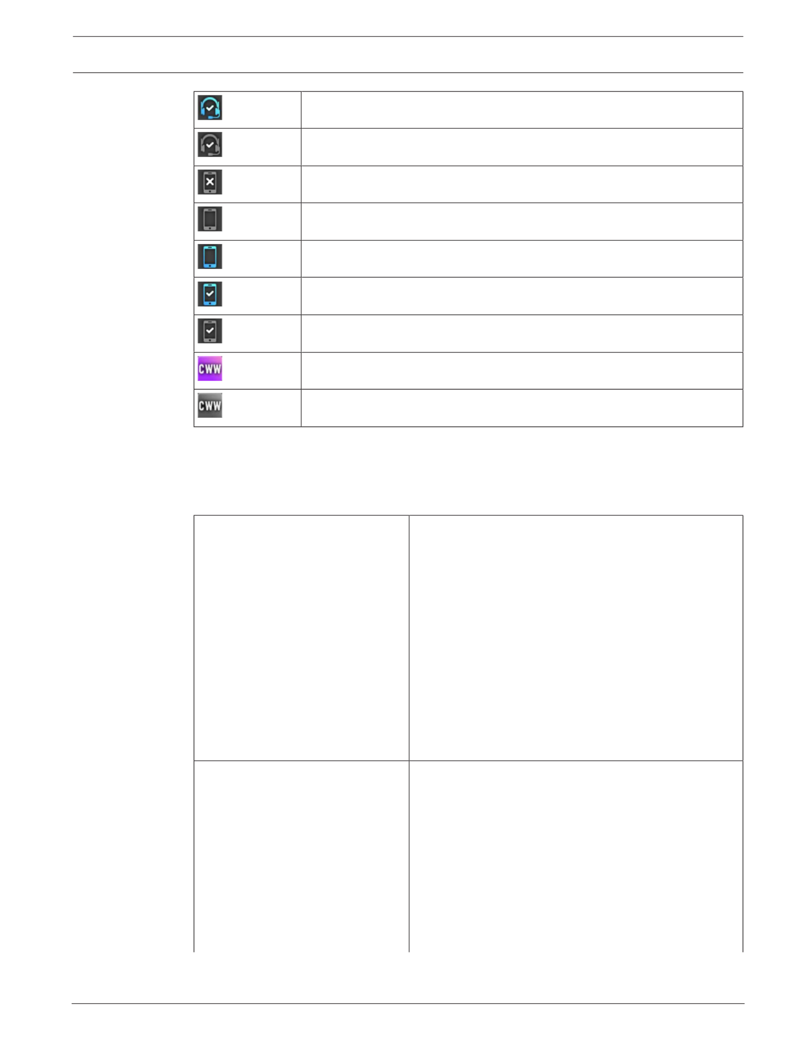
8.1 Main screen icons
The main screen icons help you get a snapshot of connection states of the DBP.
DBP connected to intercom
DBP connected to intercom, but muted
DBP expecting a connection
DBP has offers
Aux connected to the intercom
Aux connected to the intercom, but muted
Aux expecting a connection
Aux has offers
XLR headset connected
XLR headset error
3.5mm headset connected
3.5mm headset error
Bluetooth headset connected
Bluetooth headset error
Mic status normal
Mic status muted
Hot mic enabled
Low vibration call alert active
High vibration call alert active
Bluetooth headset, nothing paired
Bluetooth headset paired, not present
Bluetooth headset paired, present, not selected
DBP Digital Beltpack Basic Operation | en 27
Bosch Security Systems, LLC Technical Manual 2021-06 | 01 | F.01U.380.825
Bluetooth headset paired, present, and selected
Bluetooth headset paired, selected, not present
Bluetooth device, nothing paired
Bluetooth device paired, not present
Bluetooth device paired, present, not selected
Bluetooth device paired, present, and selected
Bluetooth device paired, selected, not present
New CWW entries are present
Existing CWW entries are present
Tab.8.1: Display Status Icons
8.2 Navigation basics
There are five basic buttons to navigate through the Digital Belt Pack menu system.
A/C shaft encoder 1Controls the master volume and by pressing the shaft
encoder, toggles the control to Key A or Key C listen
volume.
Scrolls through the menu items when in a menu or sub-
menu.
In most situations, pressing the A/C shaft encoder
button behaves the same as pressing the CLR/BACK
button. Some exceptions to this are when editing a
device name and when deleting a character.
Used to edit a menu item value/state in an active menu.
Exits the current menu item or aborts editing of the
highlighted menu item (applies to the shaft encoder as
a push button).
B/D shaft encoder 1Controls the master volume and by pressing the shaft
encoder, toggles the control to Key B or Key D listen
volume.
Controls Key B and Key D volume.
Scrolls through the menu items when in a menu or sub-
menu.
In most situations, pressing the B/D shaft encoder
button behaves the same as pressing the SEL/MENU
button. Some exceptions to this are when editing a
device name and when inserting a character.

28 en | Basic Operation DBP Digital Beltpack
2021-06 | 01 | F.01U.380.825 Technical Manual Bosch Security Systems, LLC
Enters a sub-menu, activates a menu item, or saves
changes to an activated menu item (applies to the shaft
encoder as a push button).
SEL/MENU button Enters the menu from the home screen.
Selects a sub-menu from the main menu.
Activates the selected menu item.
Saves changes in an activated menu item and
deactivates the menu item.
Dismisses popup notifications.
Confirms choice in some popup dialogs.
CLR/BACK button Shows or hides the CWW window from the home
screen.
Exits the menu (or moves back one level in the menu if
in a sub-menu).
Discards changes in an activated menu item.
Dismisses popup notifications.
Declines/aborts choice in some popup dialogs.
Displays the Connection state.
CALL button Generates outgoing CALL signals.
Acts as the SHIFT key in KP mode to allow toggling of
listen key states.
1. In some activated menu items, the A/C and B/D shaft encoders behave differently. Specifically, when editing device/domain names or IP addresses, the A/C
shaft encoder moves the cursor between letters or octets and the B/D shaft encoder change the value of the currently highlighted letter/octet. Similarly, in the
Mixer menu, the A/C shaft encoder selects the input to modify for the currently active output, and the B/D shaft encoder enables/disables the mix from the
selected input to the active output.
To , do the following:enter and navigate the menu structure
1. Press the .SEL/MENU button
The main menu structure appears in the display.
2. Rotate either to navigate through the menu.shaft encoder
3. Click the to select a menu itemB/D shaft encoder
OR
Press the to select a menu item.SEL/MENU button
4. Click the to back out of a menuA/C shaft encoder
OR
Press the to back out of a menu.CLR/BACK button
8.3 Hot keys
HOME screen:
Press and release the
SEL/MENU button
Enter menu mode.
Press and release the
CLR/BACK button
Displays the CWW.
Press CLR/BACK to dismiss the CWW.
Press and hold the CALL
button (in PL Mode)
Initiates an outgoing CALL signal for
whichever Talk keys are currently on with PL
assignments. The CALL signal lasts until you
release the CALL button

DBP Digital Beltpack Basic Operation | en 29
Bosch Security Systems, LLC Technical Manual 2021-06 | 01 | F.01U.380.825
Press and hold the CALL
button (in Keypanel
Mode)
Acts as SHIFT. Press any TALK keys while
holding the SHIFT key toggles the key to a
LISTEN state.
Release the Call key to exit SHIFT mode.
Press and hold the CLR/
BACK button and then
press and release the
CALL button.
Displays the Connection status. The
Connected popup displays if you have a
connection to an intercom and shows the port
number and alpha for the connection. The
Disconnected popup displays if you do not
have a connection to the intercom and it
shows the device name and IP address.
Press the CLR/BACK or SEL/MENU button to
exit.
While a phone call is
active, press and hold the
CLR/BACK button and
then press and hold the
CALL button.
Displays the Phone Call Management popup
window.
Use the shaft encoders to select an option and
then press the SEL/MENU button to activate
that option. There are two options, Hang Up
and To Intercom. To Intercom is a mixer toggle
on/off option.
Press CLR/BACK to dismiss.
Press and hold the CLR/
BACK button and then
press and hold the SEL/
MENU button until the
lock icon appears (or
disappears if starting
from the lockout state)
Toggle control lockout on and off.
To unlock, repeat the sequence.
Press and hold the CLR/
BACK button and then
press and release one of
the Master Volume
Controllers
Toggle between display off, display dim, and
display dark modes.
You can also use the Display Mode menu item
in the Display menu to make these changes.
While Key Volume is
active, press and hold one
of the shaft encoder
buttons until the volume
mutes (or unmutes if
starting from the mute
state).
NOTE: Use the A/C shaft
encoder to mute TALK key
A or TALK key C; use the
B/D shaft encoder to
mute TALK key B or TALK
key D.
The key assignment is muted.
To unmute the key, repeat the sequence.

30 en | Basic Operation DBP Digital Beltpack
2021-06 | 01 | F.01U.380.825 Technical Manual Bosch Security Systems, LLC
Receiving an
incoming call
signal:
Pressing the TALK key
cancels the CALL beep
and vibration.
If the TALK key is on, it stays on when you
release the TALK button.
If the TALK key is not on, it turns on and stays
on if you let go within the latching period.
MENU mode:
Press and release the
CLR/BACK button with
menu highlighted
Go back one level (exits the MENU if at the
top level).
Press and release the
CLR/BACK button with
widget highlighted
Aborts all changes made and moves the
highlight back to the menu
Press and hold the CLR/
BACK button
Exits the menu structure (aborts any widget
change in process)
Press and release the
MENU/SEL key (with a
menu item highlighted)
Invokes the highlighted menu item (may go to
a lower-level menu, or activate the widget
associated with the highlighted menu item).
Press and release the
MENU/SEL key (with a
widget highlighted)
Deactivates the widget (moves highlight back
to menu item) and saves the current widget
state (as current operating mode)
Press the A/C shaft
encoder button
Go back one level (exits the MENU if at the
top level).
Behaves the same as the CLR/BACK button in
most situations.
Press the B/D shaft
encoder button
Invokes the highlighted menu item (may go to
a lower-level menu, or activate the widget
associated with the highlighted menu item).
Behaves the same as the SEL/MENU button in
most situations.
Rotating either shaft
encoder (with a menu
item highlighted)
Moves the menu item highlight to the next or
previous menu item.
Rotating either shaft
encoder (with a widget
highlighted)
Adjusts/edits the data represented by the
widget.
For many widget types, A/C shaft encoder and
B/D shaft encoder are treated the same.
For example, adjusting a gain or brightness, or
selecting a value in a spin control, or changing
the state of an binary or tri-state widget, can
all be done by rotating either shaft encoder

DBP Digital Beltpack Basic Operation | en 31
Bosch Security Systems, LLC Technical Manual 2021-06 | 01 | F.01U.380.825
For a few widget types, the A/C shaft encoder
and the B/D shaft encoder do different
actions.
For example, while editing an IP address or a
text field (like the device name or domain),
the A/C shaft encoder moves the “cursor”
between octets or characters, and the B/D
shaft encoder adjusts the value/character at
the cursor position. The same is true for the
Mixer widget, where the A/C shaft encoder
would select the input source and the B/D
shaft encoder changes the state of the mix.
Pressing and releasing the
CALL button while in the
menu
Behaves the same as when you are on the
Home screen (for example, send CALL signal
or activate SHIFT mode, depending on
whether the DBP is in PL mode or KP mode)
8.4 UI controls
UI Control Type Description
Input field The A/C shaft encoder and the B/D shaft
encoder do different actions.
For example, while editing an IP address or a
text field (like the device name or domain),
the A/C shaft encoder moves the “cursor”
between octets or characters, and B/D shaft
encoder adjusts the value/character at the
cursor position.
Binary choice Use either shaft encoder to choose between
two options.
Tri-choice Use either shaft encoder to switch between
three options.
Spinner Use either shaft encoder to scroll through the
list of options.
Bar graph Use either shaft encoder to increase or
decrease the setting.
Mixer type The A/C shaft encoder and the B/D shaft
encoder do different actions.
For example, while configuring Mixer settings,
the A/C shaft encoder would select the input
source and the B/D shaft encoder changes
the state of the mix.
NOTE: You can select more than one option
simultaneously.

32 en | Basic Operation DBP Digital Beltpack
2021-06 | 01 | F.01U.380.825 Technical Manual Bosch Security Systems, LLC
8.5 Volume adjustment
There are two volume adjustments available on the belt pack: Master Volume and key Listen
volume.
Master volume adjustment
To , do the following:adjust the master volume
4Click or rotate .either shaft encoder
A volume bar appears on the display screen. The volume bar increases or decreases
depending on the adjustment made. The belt pack exits volume adjustment mode after a
few seconds of inactivity.
If the Master Volume is muted, the home screen displays a speaker mute symbol.
Individual listen volumes
To , do the following:adjust individual listen volumes for Key A and Key C
1. Click either .shaft encoder
The master volume activates.
2. Click the A/C shaft encoder once for key A and twice for key C.
The listen volume adjustment for the key activates and a volume bar appears on the key.

DBP Digital Beltpack Basic Operation | en 33
Bosch Security Systems, LLC Technical Manual 2021-06 | 01 | F.01U.380.825
3. Rotate the to adjust the volume.A/C shaft encoder
The volume bar increases or decreases depending on the adjustment made. The belt pack
exits volume adjustment mode after five seconds of inactivity.
i
Notice!
To adjust the volume for key B and D, follow the same instructions for key A and C, except
use the B/D shaft encoder.
Mute a PL assignment key
In PL mode, listen is always on. You can mute PL assignments so only one PL assignment is
heard.
To , do the following:mute an individual PL key
1. Click either .shaft encoder
The master volume activates.
2. Click the A/C shaft encoder once for key A and twice for key C.
The listen volume adjustment for the key activates and a volume bar appears on the key.
3. Click and hold the until Muted appears on the individual PL keyA/C shaft encoder
assignment.
4. Repeat to mute other key assignments.steps 1 through 3
To , do the following:unmute a key
1. Click either .shaft encoder
The master volume activates.

34 en | Basic Operation DBP Digital Beltpack
2021-06 | 01 | F.01U.380.825 Technical Manual Bosch Security Systems, LLC
2. Click the A/C shaft encoder once for key A and twice for key C.
The listen volume adjustment for the key activates and a volume bar appears on the key.
3. Click and hold the until Muted disappears from the individual PL keyA/C shaft encoder
assignment.
8.6 Call Signaling (PL Mode only)
Use to alert party line users that there is incoming audio on the line. By default,Call Signaling
call signaling uses the flashing call button to alert party line users. However, enabling call
alerts allows a beep or a vibration to signal incoming audio on the line. For more information
on call alerts, see
Call Alerts, page 79
.
For example, a producer starts talking to a camera operator on PL01 and the camera operator
does not hear the producer because they are not wearing their headset. The producer can
send a call signal alert to PL01 that generates a call beep or vibration (if enabled) that would
let the camera operator know someone is talking and to put their headset on.
To , do the following:send a call signal
1. Press the you want to send the signal.talk keys
2. Press and hold, or latch on the for which you want to send the signal.talk keys
The red talk key indicators turn blue and the call signal icon shows in the center of the
display. The call signal generates for as long as you hold the CALL button, and the talk
keys are still on.
3. Release the , or turn off the talk keys to end the call signal.CALL button
Refer to
– Call Alerts, page 79
8.7 Talk and Listen
The Talk and Listen functions on the DBP act like any traditional keypanel.
Talk
There are four configurable modes of talk operation: Latching, Momentary, Always On, and
Always Off. For detailed descriptions about the modes of operation and how to configure Talk
operation, see
Setup | Key Modes, page 63
.
To , do the following:talk
1. Press and hold, or latch on, the with the assignment to which you want to talk.key
2. Release the , or tap it to unlatch it, to stop talking.key
Listen
Listen key operation is the same as talk key operation, except that listen keys are always
latching and you need to press and hold the CALL/SHIFT button so that A - D key presses are
treated as listen key presses, not talk key presses.
Access to listen key states using the CALL/SHIFT button is only available in KP mode.
In PL mode, the listen keys are Always On (for PL assignments) and Always Off (for any other
type of assignment). For instruction on how to mute PL assignments on the belt pack, see
Volume adjustment, page 32
.
To , do the following:listen
1. Press and hold the .CALL button
2. Tap the for which you want to change the listen key state.key

DBP Digital Beltpack Basic Operation | en 35
Bosch Security Systems, LLC Technical Manual 2021-06 | 01 | F.01U.380.825
8.8 Call waiting window
i
Notice!
Do not confuse call signaling with incoming calls. Party lines use call signaling to notify users
that someone is trying to get their attention. Incoming calls are direct point-to-point calls
from another panel to the belt pack.
Use the (Call Waiting Window) to manage multiple incoming calls to the belt pack. TheCWW
DBP CWW displays three calls at a time with a scroll bar appearing if there are more calls (up
to nine) in the list.
A popup window appears on the HOME screen that alerts the user of an incoming CWW call.
Press CLR\BACK to dismiss the notification or press SEL/MENU to show the full CWW.
Reply to a CWW call
To , do the following:reply to a CWW call
1. On the home screen, press the .CLR/BACK button
The CWW window appears.
2. Press to answer the call.REPLY (Key D)
The REPLY key and the caller lights green.

36 en | Basic Operation DBP Digital Beltpack
2021-06 | 01 | F.01U.380.825 Technical Manual Bosch Security Systems, LLC
Remove an entry from the CWW
To , do the following:remove an entry from the CWW
1. While the CWW is open, press .CLEAR (Key C)
The CLEAR button lights red and the call disappears from the list.
Show the CWW
To , do the following:show the CWW
4On the home screen, press the .CLR/BACK button
The CWW window appears.
Scroll and select a call in the CWW
To , do the following:scroll and select a call in the CWW
4While the CWW is visible, with calls, rotate the to highlight an entry.either shaft encoder
Hide the CWW
To , do the following:the CWW list
4While the CWW window is visible, press the .CLR/BACK button
The CWW window closes.
38 en | Basic Operation DBP Digital Beltpack
2021-06 | 01 | F.01U.380.825 Technical Manual Bosch Security Systems, LLC
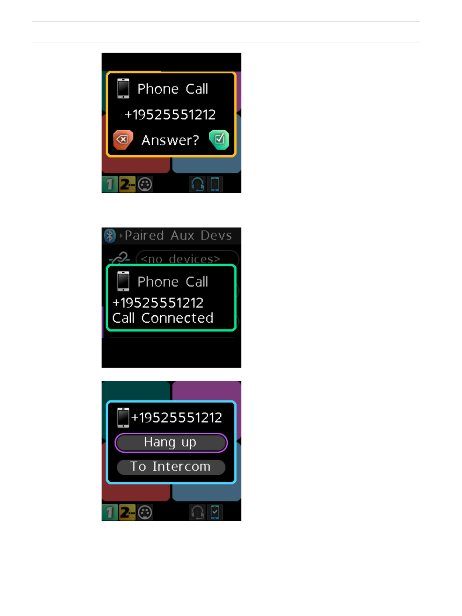
1. Press the to answer the call or press the to ignoreSEL/MENU button CLR/BACK button
the call.
A Call Connected popup notification appears.
2. Press the to display the call management screen.SEL/MENU button again
3. Press the to hang up.SEL/MENU button
A call ended popup notification appears.

40 en | Basic Operation DBP Digital Beltpack
2021-06 | 01 | F.01U.380.825 Technical Manual Bosch Security Systems, LLC
1. Rotate either to navigate to To Intercom.shaft encoder
2. Press the .SEL/MENU
The audio routes to the intercom.
i
Notice!
To Intercom is a toggled state. Turn it on and off by pressing the SEL/MENU button while on
this item.
i
Notice!
When you select To Intercom the mic audio and the phone audio go to the intercom; and,
anything heard from the intercom is heard on the phone. When you do not select To
Intercom, you only hear the Bluetooth phone audio in the headset, and any audio from the
microphone goes to the connected phone only.
8.10 Upgrade firmware
There are two ways to upgrade the DBP firmware; using the Firmware Upload Tool or using
AZedit.
ODIN 1.4.0 or later
DBP Digital Beltpack Basic Operation | en 41
Bosch Security Systems, LLC Technical Manual 2021-06 | 01 | F.01U.380.825
OMI 6.7.0 or later
AZedit 5.6.0 or later
IPedit 3.7.0 or later
FWUT
(Firmware
Upload Tool)
6.20 or later
Tab.8.2: Software requirement
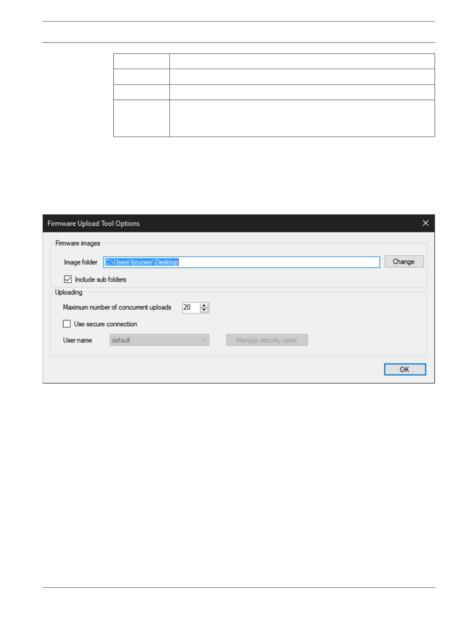
To , do the following:upgrade the firmware using the Firmware Upload Tool
1. Open the .Firmware Upload Tool
2. From the File menu, select .Options
The Firmware Upload Tool Options window opens.
3. Click the .Change button
A network folder opens.
4. Navigate to the where the firmware files resides.folder
5. Click the .OK button
The Image Folder field populates with the file path.
6. Click the .OK button
The Firmware Upload Tool Options window closes.
7. From the DBP page, select the to update.device

42 en | Basic Operation DBP Digital Beltpack
2021-06 | 01 | F.01U.380.825 Technical Manual Bosch Security Systems, LLC
8. Click the .Upload button
The Select firmware for upload window opens.

DBP Digital Beltpack Basic Operation | en 43
Bosch Security Systems, LLC Technical Manual 2021-06 | 01 | F.01U.380.825
9. Select the to upload.firmware
10. Click the .Start button
The Select firmware for upload window closes. The progression bar next to the device
shows the download progress. Once the update is complete, the device reboots
automatically.
Termékspecifikációk
| Márka: | RTS |
| Kategória: | Intercomsysteem |
| Modell: | DBP |
Szüksége van segítségre?
Ha segítségre van szüksége RTS DBP, tegyen fel kérdést alább, és más felhasználók válaszolnak Önnek
Útmutatók Intercomsysteem RTS

14 Augusztus 2024
13 Augusztus 2024
12 Augusztus 2024
11 Augusztus 2024
10 Augusztus 2024
10 Augusztus 2024
9 Augusztus 2024
9 Augusztus 2024
9 Augusztus 2024
9 Augusztus 2024
Útmutatók Intercomsysteem
- Intercomsysteem Philips
- Intercomsysteem SilverCrest
- Intercomsysteem Panasonic
- Intercomsysteem HQ
- Intercomsysteem Emos
- Intercomsysteem Vimar
- Intercomsysteem Alcatel
- Intercomsysteem Crestron
- Intercomsysteem ORNO
- Intercomsysteem Hikvision
- Intercomsysteem Midland
- Intercomsysteem Dahua Technology
- Intercomsysteem Fibaro
- Intercomsysteem DiO
- Intercomsysteem Planet
- Intercomsysteem Viking
- Intercomsysteem Chamberlain
- Intercomsysteem Foscam
- Intercomsysteem Alecto
- Intercomsysteem Russound
- Intercomsysteem Monacor
- Intercomsysteem Chacon
- Intercomsysteem Elro
- Intercomsysteem Busch-Jaeger
- Intercomsysteem ZKTeco
- Intercomsysteem Abus
- Intercomsysteem Konig
- Intercomsysteem Marmitek
- Intercomsysteem DataVideo
- Intercomsysteem Fanvil
- Intercomsysteem M-e
- Intercomsysteem Somfy
- Intercomsysteem Axis
- Intercomsysteem Becken
- Intercomsysteem Swann
- Intercomsysteem Schwaiger
- Intercomsysteem WHD
- Intercomsysteem Smartwares
- Intercomsysteem Byron
- Intercomsysteem Steren
- Intercomsysteem Siedle
- Intercomsysteem Valcom
- Intercomsysteem Bticino
- Intercomsysteem Sygonix
- Intercomsysteem Extel
- Intercomsysteem DoorBird
- Intercomsysteem Gira
- Intercomsysteem Comelit
- Intercomsysteem Aiphone
- Intercomsysteem Sonifex
- Intercomsysteem Estom
- Intercomsysteem Nortek
- Intercomsysteem Akuvox
- Intercomsysteem Bitron
- Intercomsysteem Hollyland
- Intercomsysteem Hanwha
- Intercomsysteem Leviton
- Intercomsysteem EtiamPro
- Intercomsysteem Pentatech
- Intercomsysteem Ritto
- Intercomsysteem Arenti
- Intercomsysteem Syscom
- Intercomsysteem Elcom
- Intercomsysteem Pentatron
- Intercomsysteem CyberData Systems
- Intercomsysteem COMMAX
- Intercomsysteem Bintec-elmeg
- Intercomsysteem Eartec
- Intercomsysteem Gewiss
- Intercomsysteem TCS
- Intercomsysteem Seco-Larm
- Intercomsysteem NuTone
- Intercomsysteem GEV
- Intercomsysteem Tador
- Intercomsysteem Mobotix
- Intercomsysteem FlyingVoice
- Intercomsysteem Vibell
- Intercomsysteem Toucan
Legújabb útmutatók Intercomsysteem
28 Március 2025

27 Március 2025
27 Március 2025
27 Március 2025
27 Március 2025

14 Január 2025
14 Január 2025
12 Január 2025
11 Január 2025
11 Január 2025