Használati útmutató Moog One
Moog
billentyűzet
One
Olvassa el alább 📖 a magyar nyelvű használati útmutatót Moog One (160 oldal) a billentyűzet kategóriában. Ezt az útmutatót 8 ember találta hasznosnak és 2 felhasználó értékelte átlagosan 4.5 csillagra
Oldal 1/160


IMPORTANT SAFETY INSTRUCTIONS
WARNING - PLEASE BE ADVISED THAT THIS INSTRUMENT WEIGHS 45 POUNDS, AS SUCH WE
RECOMMEND THAT TWO PEOPLE REMOVE THE INSTRUMENT FROM THE BOX AS A SAFETY
PRECAUTION. PLEASE DON’T ATTEMPT TO MOVE THE INSTRUMENT BY YOURSELF.
WARNING - WHEN USING ELECTRIC PRODUCTS, THESE BASIC PRECAUTIONS SHOULD ALWAYS
BE FOLLOWED.
1. Read all the instructions before using the product.
2. Do not use this product near water - for example, near a bathtub, washbowl, kitchen sink, in a wet basement, or
near a swimming pool or the like.
3. This product, in combination with an amplier and headphones or speakers, may be capable of producing sound
levels that could cause permanent hearing loss. Do not operate for a long period of time at a high volume level or
at a level that is uncomfortable.
4. The product should be located so that its location does not interfere with its proper ventilation.
5. The product should be located away from heat sources such as radiators, heat registers, or other products that
produce heat. No naked ame sources (such as candles, lighters, etc.) should be placed near this product. Do not
operate in direct sunlight.
6. The product should be connected to a power supply only of the type described in the operating instructions or
as marked on the product.
7. The power supply cord of the product should be unplugged from the outlet when left unused for a long period
of time or during lightning storms.
8. Care should be taken so that objects do not fall and liquids are not spilled into the enclosure through openings.
There are no user serviceable parts inside. Refer all servicing to qualied personnel only.
NOTE: This equipment has been tested and found to comply with the limits for a Class B digital device,
pursuant to part 15 of the FCC Rules. These limits are designed to provide reasonable protection against harmful
interference in a residential installation. This equipment generates, uses and can radiate radio frequency energy
and, if not installed and used in accordance with the instructions, may cause harmful interference to radio
communications. However, there is no guarantee that interference will not occur in a particular installation. If this
equipment does cause harmful interference to radio or television reception, which can be determined by turning
the equipment off and on, the user is encouraged to try to correct the interference by one or more of the following
measures:
—Reorient or relocate the receiving antenna.
—Increase the separation between the equipment and receiver.
—Connect the equipment to an outlet on a circuit different from that to which the receiver is connected.
—Consult the dealer or an experienced radio/TV technician for help.
CAUTION: Please note that any changes or modications made to this product not expressly approved by
Moog Music Inc. could void the user’s authority granted by the FCC to operate the equipment.
OPERATING CONDITIONS AND STORAGE:
For optimal performance you should use your Moog One between 50 – 95 degrees Fahrenheit or 10 – 35 degrees
Celsius. Safe operating conditions are within the range of 50 – 110 degrees Fahrenheit or 10 – 43 degrees Celsius.
Your Moog One should be stored in temperatures above 32 F (0 C) but never greater than 135 F (57 C). Do not
leave your Moog One in a vehicle on a hot day with the windows closed. Temperatures in a vehicle can exceed
175 F or 80 C.

THIS MANUAL IS A LIVING DOCUMENT THAT WILL BE UPDATED.
Please visit www.moogmusic.com/moogone to nd the most up-to-date manual.
If you are having trouble nding information about your Moog One please email:
moogonemanual@moogmusic.com or chat with us in real-time at the Moog Factory
during our operating hours (M-F, 9am-5pm EST) on www.moogmusic.com.
Registering your Moog One ensures that you receive the latest rmware and manual updates.

- D r . R o b e r t M o o g -
M u s i c a l i n s t r u m e n t s p r o v i d e
t h e m o s t e f f i c i e n t a n d r e f i n e d
i n t e r f a c e b e t w e e n h u m a n a n d
m a c h i n e o f a n y t h i n g w e k n o w .
“

THANK YOU FROM ALL OF US AT MOOG MUSIC,
With sincere pride and gratitude, we thank you for purchasing our agship polyphonic
synthesizer, the Moog One. Over ve years in development, more than 60 person-years
invested, and more than thirty years from the last polyphonic instrument from Moog, the
Moog One delivers a synthesizer experience unlike any other Moog instrument.
Before Bob Moog passed away in 2005, he encouraged us to be thoughtful about the
timing of introducing an analog poly. His advice stemmed from many years of personal
experience as he watched his company and his contemporaries exhaust their nancial and
engineering resources on the development of a polyphonic analog synthesizer. Following
Bob’s guidance, we spent many years developing new technologies through instruments like
the Minitaur and Sub Phatty – building both the condence and the capabilities to take on a
project as demanding as the Moog One.
Looking back, it is clear that the instrument our team has delivered is truly amazing.
At the original kick-off for this project, code name LAS (Long Awaited Synth), I told the team
this would be their legacy project – that there would never be another project as important or
as impactful to you (our community) as this one. I believe they have taken that to heart and
delivered the best polyphonic synth in the world.
Treasure this instrument. It will foster a lifetime of creative pleasure; spark your imagination
like nothing else; and become your musical companion for years to come. Enjoy the ride, and
know that Moog Music is here to support you on every step of your journey.
From all the employee-owners here at Moog Music, thank you.
Mike Adams
President / CEO
Moog Music Inc.

TABLE OF CONTENTS
UNPACKING AND INSPECTION
SETUP AND CONNECTIONS
MOOG ONE OVERVIEW
Presets, Synths, And Performance Sets
Voice Architecture
PILOTING MOOG ONE
Front Panel
Keyboard And Left Hand Controller
Rear Panel
MOOG ONE MODULES
Oscillators
Noise
Mixer
Filters
Envelopes
Low Frequency Oscillators
VCA
Output
Performance Set
Master Clock
Voice Allocation (Hold/Chord/Polyphony)
Modulation
Arpeggiator
Sequencer
Effects
Left Hand Controller
THE BROWSER
Loading A Preset
Loading A Timbre
Saving Presets And Synth Timbres
EDITING AND SAVING
Compare
Snapshot
Autosave
SETTINGS
Global
Hardware Settings
MIDI Control
CV Inputs
CV Outputs
Utilities
Library
Tuning
SPECIFICATIONS
SERVICE AND SUPPORT
APPENDIX A: WORKING WITH A USB KEYBOARD
APPENDIX B: MIDI LEARN
07
07
08
09
09
10
10
17
19
22
22
29
31
33
40
46
50
53
57
60
63
67
78
82
96
112
118
119
119
120
122
122
122
123
124
124
125
128
131
132
133
134
139
140
142
143
144

7
UNPACKING AND INSPECTION
Use caution when unpacking your new Moog One, and be sure that nothing is lost or damaged. Moog
recommends saving the carton and all packing materials in case you ever need to ship the instrument
for any reason.
CONTENTS
In addition to the instrument itself, your new Moog One also ships with the following items:
Power adapter and connecting power cord
Owner’s Manual
Registration Card
SETUP AND CONNECTIONS
Before you begin exploring your Moog One, you will need to provide the instrument with power, and
connect it to an audio monitoring system so that you can hear it.
WHAT YOU WILL NEED
A stand or table capable of supporting Moog One (which weighs about 45 lbs.)
A properly wired and grounded AC outlet
Two 1/4” balanced TRS to TRS or TRS to XLR cables for connecting Moog One to an
audio monitoring system, or stereo headphones outtted with a 1/4” TRS (Tip/Ring/
Sleeve) plug may be used in either of the front Headphone jacks.
NOTE: Moog One is equipped with balanced outputs, so use either 1/4” TRS to 1/4” TRS cables or 1/4” TRS
to XLR cables for the best results. Unbalanced 1/4” TS to 1/4” TS instrument cables may also be used, but are
not recommended.
CONNECTING THE POWER SUPPLY
Moog One uses a universal power supply that can accommodate AC power sources ranging from 100
to 240 volts, and either 50 or 60 cycles (Hz). The included power supply features a detachable IEC-
style power cable.
Connect the included IEC power cable to the Moog One power supply.
Connect the power supply cable to the 19-volt DC locking connector on the rear panel
of Moog One.
Connect the other end of the power cable to a suitable AC wall outlet with a protective
earth ground connection.
Finally, use the power switch on the rear panel to turn on your new Moog One.
NOTE: The power supply connects to your Moog One using a locking connector. To release this connector
from the instrument, simply press the locking tab at the base of the connector and gently slide out the
connector plug. Never pull on the cable, only the plug.
AUDIO MONITORING
With the Moog One MASTER VOLUME knob turned all the way down, connect one 1/4” cable to the MAIN L
output, and the other 1/4” cable to the output, then connect the opposite ends to a pair of L/R MAIN R
inputs on an amplied speaker system or mixing console. Adjust the Moog One volume level by slowly
turning the MASTER VOLUME knob clockwise while playing the keyboard.
If you’re using headphones, turn the knob all the way down before plugging them into HEADPHONES
either of the two headphone jacks (located on the front edge of the Left Hand Controller panel). Adjust the
volume level by slowly turning the knob clockwise while playing the keyboard. HEADPHONES
NOTE: It may take up to 5 minutes for Moog One to warm up before Oscillator tuning has stabilized,
especially if it has been outside in a car on a cold night. (Although its Oscillators are very stable,
Moog One is an analog synthesizer, after all.)
1.
2.
3.
1.
2.
3.
1.
2.
3.
4.

8
MOOG ONE
Designed to exceed every expectation, Moog One is the rst polyphonic instrument from Moog in
decades. From the original napkin sketches to the day we boxed the rst unit for shipment from the
Moog Factory here in Asheville, North Carolina, the goal has remained to create an analog, polyphonic,
programmable, and multitimbral synthesizer that is without equal. Realizing the Moog One vision
has been a journey of collaboration and discovery; a sharing of ideas between the Moog Team and
countless artists, sound designers, and synthesizer enthusiasts from around the globe. In crafting
Moog One, it was paramount to keep the interface intuitive and tactile. The hope is that your sonic
explorations will transcend the separation of artist and instrument, allowing Moog One to be the
conduit for your own creative voice.
Moog One is an analog, polyphonic, programmable, and multitimbral synthesizer; each of these terms
carries its own signicance and its own legacy.
ANALOG
The heart of the Moog One sound is its analog signal path. Since the development of the rst Moog
Synthesizer in 1963, Moog analog circuits have been renowned for their rich harmonic qualities and for
the organic nature of their expression.
POLYPHONIC
Synthesizers changed forever with the advent of polyphony. As a polyphonic synthesizer, Moog
One can independently articulate numerous voices simultaneously; up to 8 or 16, depending on the
conguration of your instrument. This voice-count designation is stamped on the serial number label
on the underside of your Moog One.
PROGRAMMABLE
Moog One is a wonderland for sound designers and tweakers, with a Front Panel hosting over two
hundred knobs and buttons. The status of each knob and button – plus countless below-the-surface
parameter settings – are stored and saved in memory in near limitless numbers of Presets. Find your
favorites using the searchable Browser. These saved Presets can also be assigned to the Front Panel’s
Performance Set for instant recall.
MULTITIMBRAL
As a three-part multitimbral instrument, Moog One is capable of playing up to three distinct Synths
simultaneously – split, layered, or zoned across the keyboard – all from within a single Preset. With each
Synth able to access its own sound parameters, MIDI channel note range, arpeggiator, and sequencer,
Moog One can create its own ensemble performances or deliver a richly layered arsenal of sound.

9
OVERVIEW
By design, Moog One is both intuitive and efcient. The iconic angled Front Panel groups single-
function knobs together by module – Oscillators, Filters, Envelopes, LFOs, etc. – in a way that is
reminiscent of the original Moog modular synthesizers, as well as the legendary Minimoog Model D.
Under the hood, a robust operating system keeps track of voice assignments, modulation routings, and
other housekeeping tasks. The interactive LCD center panel provides quick access to global settings
and reveals a second level of sound-creation parameters via the button located in the top right MORE
corner of most modules. This uid combination of hands-on control and precision parameter editing
establish Moog One as both a powerful performance instrument and a serious sound-design station.
And, of course, there’s more. Moog One provides 61 expressive keys that respond to both velocity
and aftertouch. The enhanced Left Hand Controller (LHC) features a unique three-axis touchpad,
and a pair of aluminum pitch and modulation wheels. Two control pedal inputs and a sustain pedal
jack offer further opportunities for real-time expression. Onboard sequencing, arpeggiating, and
effects processing – including premier reverbs from Eventide® – add depth and motion to your sonic
creations. Best of all, Moog One can communicate with your other gear via MIDI, USB, and through
analog Control Voltage (CV) inputs and outputs. Finally, Moog One encourages you to dive deeply
into the world of music synthesis with a programmable Matrix Modulation page connecting dozens of
modulation sources and destinations – in various amounts – using a virtual patchbay. Purists can even
bypass the entire digital Effects section to achieve a 100% analog audio path - from the Oscillators,
Filters, and Amplier, to the nal analog output jacks.
PRESETS, SYNTHS, AND PERFORMANCE SETS
Moog One allows every Preset to contain up to three separate Synths. These Synths can be split and
layered across the keyboard, while maintaining multitimbral MIDI control, and the total number of hardware
voices can be allocated between them at will. Each Synth is equipped with its own Arpeggiator and
Sequencer. Either (or both) can be easily synced to the Master Clock, or allowed to run freely. In addition,
each Synth contains its own distinct sound settings, note range, voice count, MIDI Channel, and more.
Collectively, these settings and parameters that dene an individual Synth are referred to as a Timbre.
There are two types of audio effects in Moog One: Synth Effects and Master Effects. Each Synth has
a dedicated Synth Effect that can be applied to the currently selected Synth voice only. Unlike Synth
Effects, Master Effects can be accessed by all three Synth voices simultaneously through dedicated Send
level controls located in the Master Effects module.
NOTE: Master Effects work similarly to the Send/Return architecture found on a traditional mixing console.
Timestamped, Auto-Saved “Snapshots” keep track of your in-progress edits, and prevent accidental loss
of any modied data. Moog One can store thousands of Presets. As a way of providing quick access to
specic Presets in a live performance or session environment, Moog One allows the building and saving
of up to 128 Performance Sets, which are shortcuts that select specic collections of Presets within the
vast Moog One memory. Functionally similar to traditional Bank and Preset selection, each Performance
Set offers instant access to up to 64 Presets through the 8x8 matrix of assignable Bank ( ) and A - H
Preset (1 - 8) buttons found in the Performance Set module.
VOICE ARCHITECTURE
Moog One provides three incredibly agile and advanced Voltage Controlled Oscillators (VCO). These
uniquely Moog Oscillators offer creative access to increased wave-generating dexterity and rich
harmonic content. Each Oscillator simultaneously generates a variable-width Pulse wave, plus a Saw
or Triangle (switchable) wave, also with variable shape control. Selecting Triangle allows continuous
change of the wave’s rise and fall times via the WAVE ANGLE knob -- sweeping from a Sawtooth to a
symmetrical Triangle to a Ramp (Reverse Sawtooth) wave. Selecting Saw varies the reset time of the
wave. Individually each wave offers a diverse palette of tonalities. The MIX knob sets the blend between
the Triangle/Sawtooth wave and the variable-width Pulse wave, creating a world of new and complex
wave shapes not traditionally found on an analog synthesizer. Each Oscillator is highlighted by an OLED
screen that displays a static image of the resultant wave.

10
VOICE ARCHITECTURE (Continued)
Hard Sync is available on Oscillator 2 and Oscillator 3, with Oscillator 1 being the default source of sync.
Oscillator-derived ring modulation, a multi-mode noise generator, and external audio signals are also
available as sound sources. In the Mixer module, each sound source can be routed to either a pair of
State Variable Filters (SVF), the Ladder Filter, or both. The SVF and Ladder lters can operate in series or
parallel with one another, while a dedicated MIX knob species the output balance between Filters.
In addition, each Synth also has access to four Low Frequency Oscillators (LFO) and three Envelope
Generators (EG) per voice, each equipped with a wealth of extended functions that greatly expand
the synthesis capabilities of Moog One. Commonly used modulation routings are hardwired through
dedicated front-panel controls. Further assignments can easily be made via the DEST (Destination)
buttons located within each LFO and Envelope module.
From the central LCD panel, modulation routings can be tweaked and reassigned using the vast potential
of the Modulation Matrix. Assignments can stand alone, or can be mapped through a controller (such as
the MOD WHEEL, X/Y PAD, and AFTERTOUCH). Assignable modulation modiers called Transforms
can also be utilized to morph the source signal, providing even greater creative control over modulation.
PILOTING MOOG ONE
As with the Minimoog and Memorymoog before it, Moog One features an angled control panel for
improved visibility and ease of operation. This Front Panel provides immediate access to the Moog One
sound engine and all of its synthesis parameters. Below the Front Panel you will nd an ultra-playable
61-note velocity-sensitive keyboard with aftertouch, and an expressive Left Hand Controller that
further extends the dynamic playability of this powerful analog instrument. Around back, the Moog
One Rear Panel is home to a vast array of audio, analog control voltage, and expression input and
output jacks, as well as MIDI, USB, and Ethernet ports.
FRONT PANEL
The Front Panel is divided into three sections – the Left Panel, the Center Console, and the Right Panel.
The Front Panel is always active, in that turning a knob or pressing a button will have an immediate
effect. Because Moog One is a fully programmable instrument, however, the position of the Front Panel
knobs and buttons will rarely match their currently loaded values. The exceptions are the MASTER
VOLUME and HEADPHONES knobs, which are unaffected by the loading of Presets and Timbres.
NOTE: The response behavior of the Front Panel knobs can be specied using the HARDWARE settings
in the GLOBAL menu.
LEFT AND RIGHT PANEL CONTROLS
The Left and Right Panels are populated with dedicated single-function hardware knobs and buttons
that offer immediate control of the Moog One sound engine. These controls are grouped together by
module, and modules are grouped together by type. Contained in the Left Panel are the Oscillators,
Low Frequency Oscillators (LFO), Noise Generator, Ring Modulator, Arpeggiator, Sequencer, Master
Clock, Chord, and Polyphony modules. A distinctive feature of each Oscillator module is the dedicated
OLED window, which provides a graphic representation of the composite waveform being output to
the Mixer. Contained in the Right Panel are the Mixer, State Variable Filters, Ladder Filter, Envelope
Generators (EG), VCA, and Output modules. Also found in the Right Panel are the Synth Effect
parameters and the Master Effect sends, which provide access to numerous studio-grade effects,
including acclaimed reverbs from Eventide®.
With the exception of the MASTER VOLUME, HEADPHONES, and MASTER CLOCK controls, all of the
parameters available on the Left and Right Panels will control the currently selected Synth(s) only.

11
KNOBS AND BUTTONS
In this manual, when referring to a specic knob, button, or jack, the name of the control will be
presented in ALL BOLD CAPS as it appears on the Moog One front or rear panels - for example:
CUTOFF knob, SHIFT button, MIDI OUT jack, etc.
Also, in this manual, when referring to the parameter affected by the controller, no bold is used, and only
the rst letter is Capitalized – for example: the Cutoff frequency, the Shift state, the Preset Library, etc.
KNOBS
There are three different types of knobs found on
Moog One. Traditional knobs have a xed functional
destination and rotational limitations. Soft Knobs,
which change assignment based on the currently
selected item on the LCD screen, can be rotated
innitely and are only found below the Center
Console Display. Finally, there is a large Master
Encoder located in the Center Console that allows
for scrolling and selection (by pressing the knob).
BUTTONS
Pressing a translucent button will toggle its function On (LED lit) and Off (LED
dark), while pressing a solid red button selects a function, state, or option as
indicated by a lit LED on the panel.
MORE
Nearly every module is equipped with a triangular MORE button located in its
upper right corner. When a MORE button is pressed, the Center Console Display
screen reveals additional parameters specic to that module. These additional
parameters are accessed and controlled using the Center Console knobs and
buttons.
NOTE: Pressing an illuminated MORE button will close that parameter window and
recall the HOME screen.
DEST
The four LFOs and three EGs each feature a dedicated DEST (Destination)
button that provides a simple shortcut for assigning that LFO or EG as a
modulation source to a particular destination. Once the DEST button is pressed, a
modulation routing screen will open in the Center Console Display; the next Front
Panel parameter that is touched or tweaked will become the new modulation
destination. As soon as the assignment is made, the modulation amount and
additional parameters will appear on the screen.
Traditional
Master Encoder
Soft

12
CENTER CONSOLE
The upper portion of the Center Console is built around an interactive graphic interface that provides
access to a secondary layer of sound design parameters, as well as other Moog One Global parameters.
The Center Console Display is operated via four Soft Buttons and four Soft Knobs, all of whose functions
change based on the current screen.
Additionally, there is a large Master Encoder that can be used to scroll through lists and make selections
by pushing down on the knob momentarily. In general, parameters are displayed above their respective
Soft Knobs in groups of four. Here, values can be edited using the four Soft Knobs. If more than four
parameters are available, rotating the Master Encoder will call up the additional rows. Together, the Soft
Buttons, Soft Knobs, and Master Encoder provide effortless navigation of the graphic interface.
Surrounding the Master Encoder
are eight dedicated buttons.
HOME
Pressing the button calls up the HOME HOME screen, which displays the name
of the active Preset, the names of the Timbres within the Preset, the respective
keyboard ranges and On/Off status of Synth 1, 2, and 3, and the current Master
Clock tempo.
Soft Buttons
Soft Knobs
Master Encoder

13
As notes are played on the keyboard,
key range indicators will ash to show
which Synth(s) are being played from
those keys. In addition, the HOME screen
shows any tags that have been assigned
(Type, Category, Mood, Group) to make
the Preset more discoverable in a search.
NOTE: Pressing the HOME button will
exit any currently selected screen and
return to the HOME screen.
SETTINGS
This button provides access to all Moog One Global, Library, and Tuning parameters.
MOD
The MOD button opens the Modulation Matrix screen, where any possible
modulation source can be freely routed to any possible modulation destination,
and in any amount. A controller, such as the wheel, may also be assigned MOD
in order to add articulation and expression to a modulation assignment.
Additionally, Transforms can be inserted to place high and low limits on the
modulation source signal, or to square or cube the modulation source control
signal to further expand the variation and expressivity of the powerful Moog
One modulation engine.
NOTE: When editing or creating a Modulation Matrix, pressing down on the Master Encoder will toggle
back and forth between two sets of parameters (upper and lower) available for each modulation routing.
DELETE
The DELETE button is used to remove a modulation routing row, eliminate
sequence data, and more. Its specic function is contextual, and is determined
by the currently selected screen and parameter.
SNAPSHOT
Pressing SNAPSHOT performs a “micro-save” of the current data as you are
editing. Each Snapshot is time stamped, so there is no need to keep saving the
data manually under a new Preset name while you are editing. Any Snapshot
can be recalled, auditioned, or designated as the “ofcial” version of a Preset
when you are saving the data. To view the Snapshots saved with the current
Preset, hold the + buttons on the Front Panel.SHIFT SNAPSHOT

14
SAVE
The SAVE button begins the Save process that allows you to store the current
settings of the instrument as a Preset. During the Save process, you will also
have the ability to add names to the individual Timbres (1, 2, and 3) that are
contained within the Preset.
NOTE: A full explanation of the save process can be found in the “Saving A
Preset” section on page 118.
NOTE: The SAVE button will light dimly if any parameters have been altered from their originally saved
value, reminding you to save your changes if you wish to make them permanent.
COMPARE
Pressing the button places a copied version of the current Preset COMPARE
parameter settings in a separate buffer, so you can tweak one version of a
Preset and always compare it to the saved version as you edit.
NOTE: COMPARE Pressing SHIFT and simultaneously ( ) creates SHIFT + COMPARE
a new initialized Preset using the Moog One default sound parameters and settings.
SHIFT
The button is most often used in conjunction with another controller or SHIFT
function. For example, holding the button while operating a Soft Knob SHIFT
parameter allows the value to be edited at a ner level of resolution. SHIFT
operations can be performed by holding down the button as you operate SHIFT
the controls. Alternatively, you can enter mode by pressing and releasing SHIFT
the SHIFT button. The button will blink, and any operation performed will
behave as if the SHIFT button is being held. Moog One will remain in this state
until the button is pressed again, and the blinking has stopped.SHIFT
WORKING WITH SYNTHS
Tweaking knobs and pressing buttons has a direct effect on the sound of Moog One. But what exactly
is the Front Panel controlling? Remember, a Preset is comprised of up to three Synths -- and one Synth
(or more) is always assigned to the Front Panel.
The active Synth is selected using the SYNTH 1, and buttons in the Panel Focus module, which 2 3
allows the Front Panel knobs and buttons to only affect the currently selected Synth(s). Pressing any
SYNTH SYNTH button by itself will select just that one Synth. Holding one button while pressing
additional SYNTH buttons will select multiple Synths, and allow any tweaks or edits to be applied to all
of the selected Synths simultaneously.
NOTE: When multiple Synths are selected, the MORE pages and the sound engine status LEDs in the
LFO, Sequencer, and Arpeggiator modules will reect the status of the most recently selected Synth.
This buttons will be lit SYNTH button will be illuminated at full brightness, while the initially held SYNTH
at a lesser brightness.
15
WORKING WITH SYNTHS (Continued)
The active Synth can be turned On or Off using the ON button located in the Keyboard Control
module. In addition, each Synth can be quickly zone-limited to a specic area of the keyboard. To do
this, press the LOW RANGE button (the LED will light) and then press a key on the keyboard to set the
lowest playable note for the selected Synth (the LED goes dark). Next press the HIGH RANGE button
(the LED will light) and press a key on the keyboard to set the highest playable note for the selected
Synth (the LED goes dark). Additional visual conrmation is provided on the HOME page, where the
keyboard range for each Synth is shown in red if Keyboard Control is , and grayed-out if it is Off.ON
TIP: Pressing both the LOW RANGE button and the HIGH RANGE button at the same time will expand
the zone of the active Synth to its full note range of G0 to C10 (MIDI Note 0 - 127).
TIP: Press any SYNTH button while holding SHIFT to solo the selected synth. Repeat to return to
standard behavior.
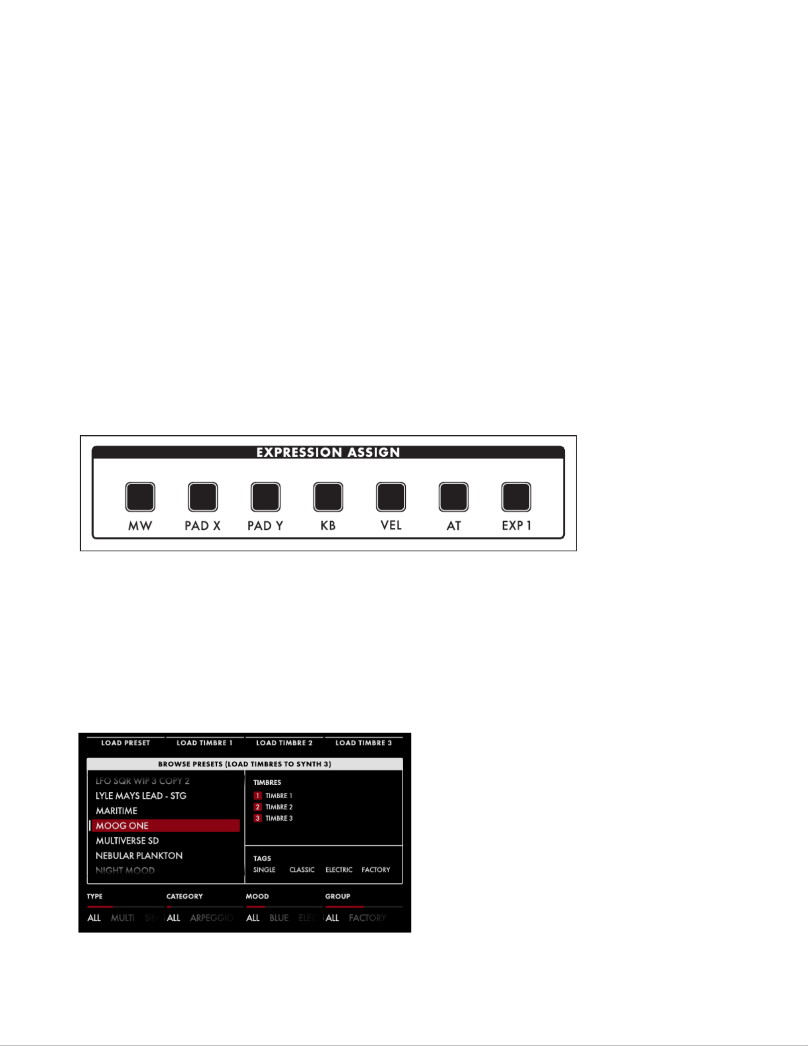
ADDING EXPRESSION
The Expression Assign buttons provide a convenient way to instantly assign a controller as a
modulation source to a specic parameter. Simply press any Controller button in the Expression Assign
module, and then tweak a knob or press a button to link the selected controller to that parameter.
Once a modulation path has been created, the Quick Assign modulation screen will appear in the
Center Console Display. Additional parameters may be accessed here.
The available controllers are:
• MW (Mod Wheel)
• PAD X (Pad Position X Axis - horizontal motion)
• PAD Y (Pad Position Y Axis - vertical motion)
• KB (Keyboard Note Value)
• VEL (Keyboard Velocity)
• AT (Aftertouch)
• EXP 1 (Expression Pedal input 1)
SELECTING A PRESET
Moog One can store a nearly innite
number of Presets that may be searched
and ltered in a variety of ways. From
the HOME screen, press the BROWSE
PRESETS Soft Button at the upper left of
LCD to open the Preset Browser.

16
SELECTING A PRESET (Continued)
Use the Master Encoder to scroll through the list of available Presets that are displayed on the left
pane. Pressing down on the Master Encoder will load the selected Preset; you can also use the LOAD
PRESET Soft Button at the top of the screen.
The upper-right pane lists the Timbres used to create this Preset. The lower-right pane lists any tags
that have been assigned to this Preset. Tags narrow the list of available selections, making it easier to
nd a specic or appropriate Preset.
The four Soft Knobs at the bottom of the screen can choose which Presets will be displayed according
to TYPE, CATEGORY, MOOD, and GROUP. All tags are user denable, with the exception of TYPE.
Only TYPE has xed options - SINGLE, LAYER, SPLIT, and MULTI. Generally, one would use SINGLE
for a Preset using a single Synth. SPLIT for multiple Synths playing in different areas of the keyboard,
LAYER for multiple Synths stacked on the same keys, and MULTI for a Preset combining SPLITS and
LAYERS, etc.
Presets in Moog One can also be instantly recalled using Performance Sets; the current Performance
Set is always accessible from the lower Right Panel. Each Performance Set can recall up to 64 Presets,
that are arranged in eight Banks ( ) of eight Presets ( ). Performance Sets allow you to have A - H 1 8-
select Presets ready and on tap for instant access during a live performance - or even a studio session.
To assign the active Preset to the currently loaded Performance Set, simply press the Bank ( ) A - H
button of your choice, then press and hold the desired Preset ( ) button for 1 second. The Preset 1 9-
button will blink rapidly to let you know your Preset is now assigned to that location.
NOTE: The Performance Set does not itself provide storage of Presets; instead, the Performance Set
saves “pointers” that direct Moog One to recall a specic Preset from its memory banks.
To select a Preset from a Performance Set, simply press a Bank button ( ), and then press a A H -
Preset button ( ) to choose a Preset from your selected Bank.1 8 -
NOTE: Buttons that are dimly lit indicate that there is a Preset assigned to that button. Buttons that
are completely dark indicate that no Preset has been assigned.
TIP: There is a SHOW BANK PREVIEW option
available (under SETTINGS - GLOBAL -
HARDWARE SETTINGS). When this function
is On, pressing a Bank button will open a
screen showing all of the Presets assigned
to that Bank.

17
KEYBOARD
Moog One features a premium quality, 61-note keyboard with velocity sensitivity and aftertouch, which
are both available as modulation sources. Selectable sensitivity curves are also available to further
tailor the keyboard’s response to your personal playing style.
LEFT HAND CONTROLLER
Located at the left end of the
Moog One keyboard, the Left Hand
Controller (LHC) provides a number
of tools that enhance the playability,
performance, and expression of this
powerful instrument.
OCTAVE
The OCTAVE buttons allow the keyboard to be shifted up or down
by octave. Pressing both OCTAVE buttons at the same time will reset the
keyboard to its Default Octave.
NOTE: Press and hold both OCTAVE buttons to send a MIDI Panic (All Notes
and Controllers Off) message.
GLIDE
Glide delivers a smooth, continuous change in pitch when moving from
one note to the next. In addition to the knob and the GLIDE RATE GLIDE
ON button, Moog One offers three types of Glide, as well as additional
parameters for Legato, Glissando, and Gated Glide. Pressing the MORE
button on the Left Hand Controller brings these parameters into view in the
Center Console Display.
X/Y PAD
The X/Y PAD is a highly expressive, multidimensional touch surface
whose X and Y axes can be easily assigned to a variety of musically useful
destinations. There is also a third assignable axis that can sense Pressure
on the surface of the pad. The can operate in either a latching or X/Y PAD
non-latching manner as determined by the state of the X/Y HOLD button.
If the button is illuminated, the held value of the X/Y HOLD X/Y PAD
can be saved as part of a Preset, similar to the wheel amount. Pad MOD
pressure also sends a Gate On signal, available as a Control Source in the
Mod Matrix.

18
PITCH
The spring-loaded PITCH wheel is used to bend the pitch of the Moog One Oscillators
up or down by a predetermined amount. The Pitch Bend Up and Pitch Bend Down
range can easily be specied by pressing the MORE button on the Left Hand Controller
and adjusting each parameter accordingly.
MOD
The MOD wheel is an assignable Controller that is most commonly used to manually
determine the amount of modulation being applied from a Source to a Destination. In
the case of the Moog One, the MOD wheel can also be assigned to multiple locations
simultaneously through the Mod Matrix and EXPRESSION ASSIGN Buttons.
NOTE: The MOD wheel position can be saved as part of the Preset.
HEADPHONES
Located just below the is a pair of front-facing stereo headphone X/Y PAD
outputs. Use the HEADPHONES knob in the Output module to set the
volume level for both headphone outputs.

19
REAR PANEL
The Moog One Rear panel is equipped with a full complement of audio jacks, communication
ports, MIDI connectors, and pedal ports – plus congurable CV In and CV Out connections – to
accommodate nearly any use.
POWER
Moog One uses an external power supply/adapter that
connects using a locking multi-pin cable. Orient the cable
correctly and slide it straight in until it locks. To remove the
cable, depress the locking tab on the connector plug and slide
the cable straight out. Hold the cable by the locking plug --
never pull on the cable directly. The Moog One On/Off switch
is located adjacent to the power port.
MAIN OUT/SUB OUT
Moog One features two sets of
stereo outputs, the MAIN L (Left)
and MAIN R (Right), and the SUB L
(Left) and (Right). Both the SUB R
MAIN OUTS and the SUB OUTS
feature 1/4” balanced TRS jacks.
Each Synth can be assigned to
either set of outputs – or both.
NOTE: The SUB OUTS are not affected by the MASTER VOLUME knob.
INSERT 1 2 3 4
Four INSERT jacks are provided.
Their routing is controlled by
pressing the Output Module MORE
button. The tip of this tip-ring-
sleeve jack is wired as the Send,
so each jack can be used INSERT
as an individual output when used
with a standard unbalanced TS 1/4”
cable. Each Insert jack can also be
used with a Y-conguration insert
cable to achieve true insert functionality. The signal is returned to Moog One via the ring connection
of the tip-ring-sleeve jack. This allows the active Synth to be sent to, and returned from, an external
processor, while still maintaining its place in the internal mix. In addition, the ring/return connectors
on adjacent pairs of inserts (1 2 3 4 & , & ) are stereo normalled, so that they can be used as stereo
returns. The way this works is that if nothing is connected to the return of Insert 2, the signal returning
via Insert will be summed to both the and 1MAIN L MAIN R outputs. Similarly, if nothing is connected
to the return of Insert , the signal returning via Insert will be summed to both the and 4 3 MAIN L
MAIN R outputs.

20
REAR PANEL (Continued)
EXT INPUT
Moog One provides an External Audio Input
featuring a Neutrik connector, capable of
accepting either a balanced XLR cable, a balanced
1/4” TRS cable, or an unbalanced 1/4” TS cable.
The knob can adjust the input gain from TRIM
-9 dB to +65 dB. There is also a Line Level ( ) LINE
input equipped with a 1/4” balanced TRS jack
that can accept a balanced 1/4” TRS cable, or an
unbalanced 1/4” TS cable. These external inputs
show up in the Moog One Mixer MORE screen as an additional sound source with a dedicated channel,
although dedicated controls do not exist on the hardware Front Panel. From the Output module’s
MORE page, the LINE Input can be routed to the Insert buss, and the XLR/1/4” combo jack can be 3
routed to Insert .4
CV (CONTROL VOLTAGE) I/O
A control voltage is an analog control signal that allows the parameters and functions on one instrument
to interact with the parameters and functions of another instrument in the analog domain. In the days
before MIDI and USB, control voltage was the primary method for interconnection between synthesizers,
and it is still the primary method of interfacing with modular and Eurorack synthesizers today.
Moog One is equipped with two dedicated jacks (CV IN 1 2, ) and four jacks (CV OUT 1 2 3 4, , , ).
Additionally, both expression pedal inputs (EXP 1, EXP 2) and the pedal input may also be SUSTAIN
congured for use as control voltage inputs for further analog control.
MIDI (5-PIN DIN)
Moog One offers 5-pin DIN MIDI IN, MIDI
THRU, and MIDI OUT jacks to connect directly
to other MIDI devices, such as sequencers,
drum machines, interfaces, etc. Each Synth in a
Preset can operate on a separate MIDI Channel
for multitimbral control via external MIDI
devices. In addition to note data, the MIDI ports
can be congured to send and/or receive MIDI
Clock, controllers, expression, SysEx, and more.
21
REAR PANEL (Continued)
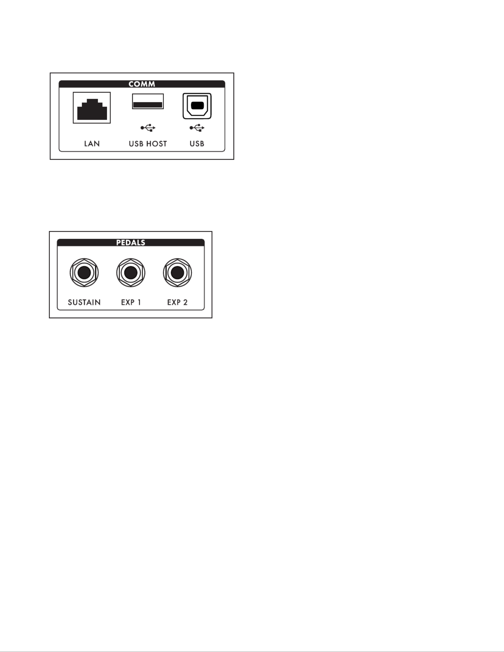
COMM (COMMUNICATION PORTS)
The LAN port enables Moog One to connect
directly to a computer network using a CAT-5
cable, which allows for remote servicing and
future expansion. The port allows USB HOST
for updating the Moog One rmware from a
USB thumb drive, and provides a convenient
way to backup instrument data onto portable
USB drives for safe keeping and backline
applications. Additionally, the USB HOST port
can also incorporate any class-compliant MIDI device (one that requires no additional software drivers)
into Moog One operations. The USB port found here allows Moog One to communicate directly with
your computer via USB, sending and receiving MIDI and other system data.
PEDAL JACKS
Moog One includes three pedal input jacks. One
is congured as a sustain ( ) pedal input, SUSTAIN
and the other two as expression (EXP 1, EXP 2)
pedal inputs. These inputs can be used to control
nearly any Moog One parameter, allowing for a
tremendously expressive performance.
NOTE: Keep in mind that these pedal jacks can also be used to receive CV signals (via 1/4” TS cables)
from other synth modules, Eurorack systems, etc.

22
OSCILLATORS
Oscillators are the primary sound source for any synthesizer. Moog One Oscillators have no physical
moving parts like a guitar’s string or a clarinet’s reed. Instead, the Oscillators generate an electronic
signal that changes direction very rapidly. The patterns created by these uctuations determine the
waveform, or wave shape, which in turn determines the harmonic content of the signal. Moog One
features three independent Oscillators that are nearly identical in design.
Each Oscillator generates two waveforms simultaneously; these can be blended via a dedicated
MIX control into a single complex, composite wave. For the rst waveform, either a Triangle or
Sawtooth wave can be chosen. Applying the WAVE ANGLE control to the Triangle wave can change
the symmetry of the waveform, allowing the Triangle to reach a Ramp or Sawtooth shape at either
extreme. Applying the WAVE ANGLE control to the Sawtooth wave can vary the reset time, delivering
increased harmonic diversity. The second waveform is a Pulse wave with a variable Pulse Width. As
with the PULSE WIDTH knob, the TRI/SAW WAVE ANGLE knob can be modulated from another
controller or parameter.
Together, their combined signals can be used to create an endless array of wave shapes that determine
each Oscillator’s nal sonic output. The OLED screen in the center of each Moog One Oscillator
provides a static image of this composite waveform.
NOTE: The static image displayed on the OLED is created by the Oscillator’s parameter settings only,
and does not reect any real-time modulation routings that may also be affecting the nal waveform.
OCTAVE (32’, 16’, 8’, 4’, 2’)
Rotating the OCTAVE knob will change the pitch of the Oscillator by
octave. The historical “foot” settings are a musical convention that
relates to pipe lengths on a pipe organ. The 8’ setting is considered
standard, and will pitch the “C” in the middle of the Moog One
keyboard (MIDI Note #60) at “Middle C.”
FREQUENCY (-7 to 0 to +7)
While the OCTAVE knob sets the Oscillator pitch in octave units, the
FREQUENCY knob continuously varies the Oscillator pitch over a range
of +/- 7 semitones (up or down a perfect fth).

23
OSCILLATORS (Continued)
BEAT FREQ (-7 to 0 to +7)
Slightly detuning multiple Oscillators is a classic method for creating
huge analog sounds. Moog One adds a Beat Frequency control that
can offset the pitch of any Oscillator by a constant amount, which is
measured in Hertz (Hz). Use the BEAT FREQ knob to create a slight
tuning offset per Oscillator. This method provides consistent, musical
results over the entire keyboard.
WAVE (TRI, SAW)
The button is used to select either the WAVE TRI (Triangle) or SAW
(Sawtooth) mode for the rst wave generator.
WAVE ANGLE
The function of the WAVE ANGLE knob is determined by the
WAVE button selection.
TRI (TRIANGLE MODE)
With the button set to WAVE TRI (the will be lit), rotating the TRI LED
WAVE ANGLE knob will continually vary the wave shape, changing the
relationship between the rising and falling segments of the wave.
The center position will create a Triangle wave. Rotating the knob to the
far left will produce a wave shape closer to a Sawtooth wave; rotating the
knob to the far right will produce a Reverse Sawtooth (or Ramp) wave.
NOTE: In TRI mode, the rising
and falling phases of the wave
both scale with pitch -- both
get faster at higher pitches, and
both get slower at lower pitches.
TIP: In TRI mode, try modulating the WAVE ANGLE to vary the rise and fall segments of the wave,
producing a wide variety of timbres traditionally unavailable on an analog synthesizer.
SAW TRIANGLE RAMP
24
OSCILLATORS (Continued)
SAW (SAWTOOTH MODE)
With the button set to will WAVE SAW (the SAW LED
be lit), rotating the WAVE ANGLE knob will continuously
vary the reset time of the Sawtooth wave. Rotating the
knob hard left will produce a classic Moog Sawtooth
wave with a 6 µs (microsecond) reset time. As the WAVE
ANGLE knob is rotated to the right, the reset time of the
Sawtooth wave is increased, creating a darker and less aggressive timbre. The Wave Angle range is
from 6 µs to 1 ms (millisecond).
NOTE: In SAW mode, modulating the Wave Angle will vary the reset time of the wave, resulting in
dynamic variations of timbral complexity.
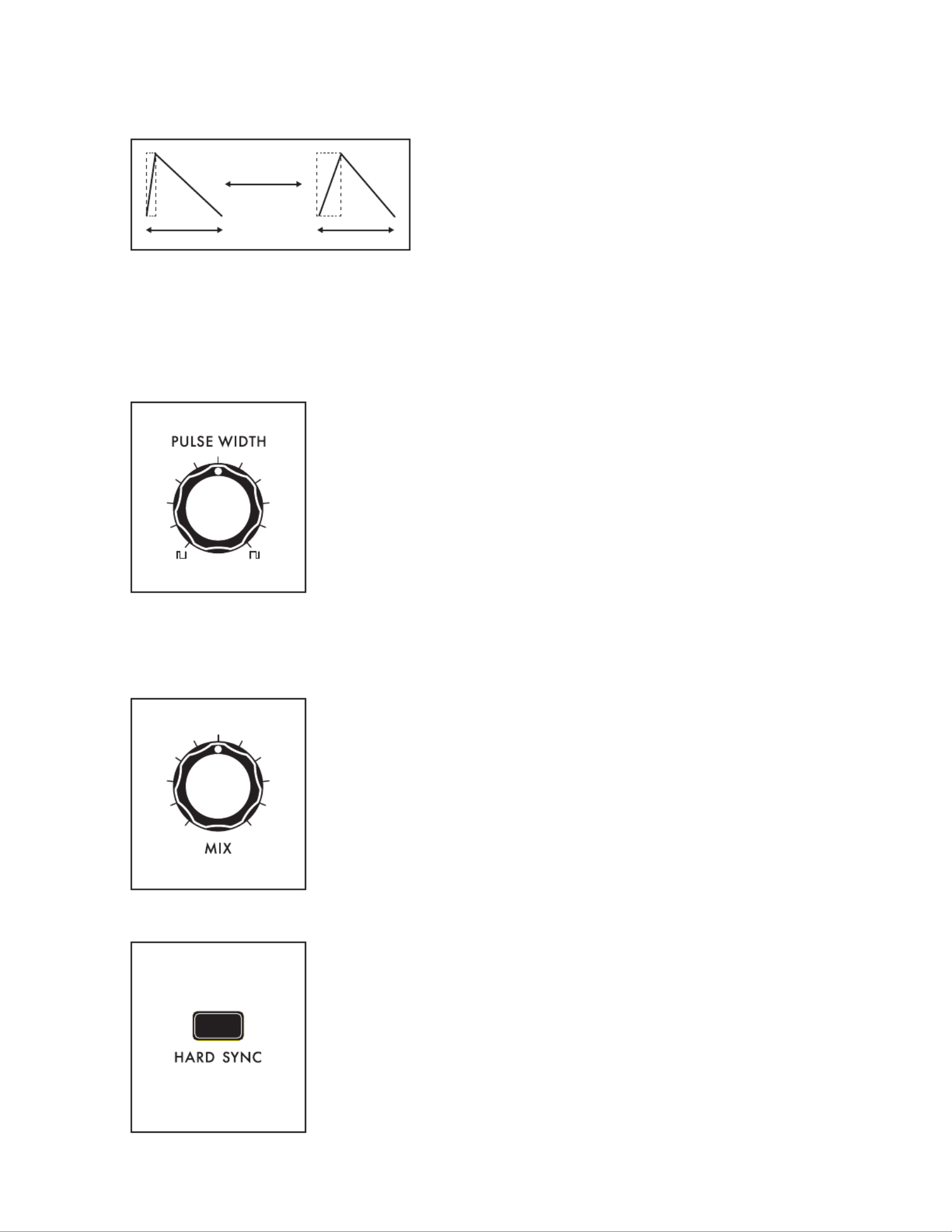
PULSE WIDTH
The second wave generator in each Oscillator creates a pulse wave.
Rotating the PULSE WIDTH knob will vary the duty-cycle (Pulse Width)
of the wave. Rotating the PULSE WIDTH knob to the far left will create
a narrow pulse with a short duty cycle; the center position will produce
a square wave (50% duty cycle); rotating the knob to the far right will
produce a wide pulse with a long duty cycle.
NOTE: The inverse of a narrow Pulse Wave with a 20% “on” time is a wide
Pulse Wave with a 20% “off” time. Graphically, they are mirror images of
each other, and their harmonic contents are identical. However, it is the
smooth cyclic transition from one to the other that gives Pulse Width
Modulation (PWM) its distinctive sound.
MIX
Using the MIX knob, you can create a unique and intricate analog wave
shape by combining the outputs of the Triangle/Sawtooth generator
and the Pulse/Square generator. The knob determines the blend MIX
between the two, and the resultant waveform is shown in the individual
OLED window for each Oscillator. Rotating the MIX knob to the far left
outputs the Triangle/Sawtooth only; the center position provides an
equal mix of the two generators; rotating the knob to the far right MIX
will output the Pulse/Square only.
HARD SYNC (OSCILLATOR 2 and OSCILLATOR 3 only)
When an Oscillator is sync’d to the phase of another Oscillator, the
sync’d Oscillator is forced to reset itself to match every waveform peak
of the master Oscillator. As the sync’d Oscillator struggles to keep up,
the resulting wave shape can become more and more complex.

25
OSCILLATORS (Continued)
The sound can become aggressive, metallic, or even
exhibit elements of comb ltering. Adding modulation
to the frequency of a sync’d Oscillator can greatly
enhance this effect. Moog One sets Oscillator 1 as the
Master Oscillator by default. Use the HARD SYNC
button to force the selected Oscillator(s) to sync to
Oscillator 1.
OSCILLATOR MORE PAGE
Pressing the triangular MORE button in the upper right corner of any
Oscillator module will reveal a second level of parameters that can
be accessed and modied using the Soft Knobs and Master Encoder
in the Center Console. These additional parameters are displayed
in the bottom portion of the screen. The left pane shows a static
representation of the nal wave shape output from the Oscillator.
NOTE: The static image displayed on the screen is created by the
Oscillator’s parameter settings only, and does not reect any real-time
modulation routings that may also be affecting the nal waveform.
The right pane shows the current value of the Front Panel hardware parameters for this module.
NOTE: Pressing the (now) illuminated button will exit the page and recall the HOME screen.MORE MORE
CHANGING THE VALUE
Rotate the Soft Knob below each
parameter name to change its value. In
some cases, the Soft Knob simply turns a
function on or off. In other cases, the Soft
Knob may choose from a range of values
or settings.
SELECTING A ROW
The scroll bar at the right edge of the
screen indicates the current row. Rotating
the Master Encoder to the right will select
the next available row of parameters.
Rotating the Master Encoder to the left will select the previous row. Once selected, rotate the Soft
Knob below each parameter name to change its value.
OSCILLATOR 1
HARD SYNC’D OSCILLATOR

26
OSCILLATORS (Continued)
VCO MODE (SAWTOOTH, TRIANGLE)
This parameter shows the status of the button on the front panel. This function can also be WAVE
controlled here.
PITCH TRACKING (0 200%)to
With this parameter set to 100%, the pitch of the Oscillator will track the keyboard as normal. In some
cases you may want to change this value. For example, at 0%, the Oscillator would play the same pitch,
regardless of the note played. Another example would be to set an Oscillator to Hard Sync, and utilize
an excessive value (150% - 200%) to enhance the effect.
NOTE-ON RESET (OFF, ON)
Normally, an Oscillator is constantly running, and each new note played begins from the current point
in the waveform cycle. When NOTE-ON RESET is On, the phase of the Oscillator is reset to zero with
each new note-on command, which can make for extremely punchy bass sounds.
BEND OFFSET
The Bend Offset amount is set individually for each oscillator, and is combined with the per-Synth
Pitch Bend Up and Down values set on the LHC MORE page. Bend Offset provides separate values for
Bend Up and Bend Down, and each can be set to either a positive or a negative value. In this way, the
Pitch Bend wheel can be used to resolve each oscillator to a specic note or interval at either end of its
travel, allowing for creative harmonies and chords to be introduced as part of a performance.
BEND UP OFFSET (-24 to 0 to +24)
This parameter species the amount of Pitch Bend Offset applied to the Oscillator when the
Pitch Bend wheel is moved Up. When the value is set to zero no offset is added. Negative
offset values will bend the pitch down; positive values will bend the pitch up. The range is +/-
24 semitones (two octaves).
BEND DOWN OFFSET (-24 to 0 to +24)
This parameter species the amount of Pitch Bend Offset applied to the Oscillator when the
Pitch Bend wheel is moved Down. When the value is set to zero no offset is added. Negative
offset values will bend the pitch down; positive values will bend the pitch up. The range is +/-
24 semitones (two octaves).
HARD SYNC SRC. (OSCILLATOR 2 and OSCILLATOR 3 only)
The default source for Hard Sync on Oscillator 2 and Oscillator 3 is Oscillator 1. Here, a different
oscillator can be designated as the Hard Sync source.
OSCILLATOR 2 (VCO 1, VCO 3)
OSCILLATOR 3 (VCO 1, VCO 2)

27
OSCILLATOR COMMON PARAMETERS
Just below the Oscillator section is a set of controls that affect all three of the oscillators in the active
Synth. These parameters are instantly available and are conveniently hard-wired to commonly-used
modulation applications.
PITCH MODULATION
These modulation parameters affect the pitch of all three oscillators.
LFO 1 AMT (0 to 10)
Turning this knob will determine the amount of LFO 1 being applied as
a modulation source to the pitch of all three Oscillators. The higher the
value of this knob, the deeper the modulation effect.
MOD EG AMT (-10 to 0 to +10)
Adjusting this knob will determine how much of the control signal from
the Modulation Envelope Generator is being applied as a modulation
source to the pitch of all three Oscillators. The center position equals
zero and produces no effect. Rotating the knob to the right increases
the amount of signal; rotating the knob to the left inverts the MOD EG
amount of MOD EG signal.
RING MOD (RING MODULATOR)
Ring Modulation analyzes two input signals to create a new, complex output signal. Mathematically,
this output signal is the combined sum and difference of the frequencies of the input signals. Ring
Modulation is known for creating metallic, robotic and inharmonic sounds. The output of the RING
MOD appears in a dedicated channel in the Moog One Mixer module.
NOTE: The oscillator signals being fed into the RING MOD are tapped directly from the Triangle/Sawtooth
generator, and are not affected by the Oscillators’ knobs or the Oscillator knobs.PULSE WIDTH MIX
TIP: Try altering the amount of one of the Oscillators (using the PITCH TRACKING MORE button) to
emphasize the effect. You may want to reduce the volume of the altered Oscillator.RING MOD
SOURCES (1 – 2, 2 – 3)
Use this button to choose which pair of Oscillators will be fed into the
RING MOD. The corresponding LED will light.
1 – 2
Oscillator 1 and Oscillator 2 will drive the Ring Modulator.
2 – 3
Oscillator 2 and Oscillator 3 will drive the Ring Modulator.

28
WAVEFORM MODULATION
These modulation parameters affect the waveform of the Oscillators. Both knobs are applying LFO 3 to
the Oscillator wave shape.
WAVE ANGLE / LFO 3 AMT (0 10)to
Turning this knob determines the amount of LFO 3 that is applied as a
modulation source to the Oscillators’ Wave Angle parameter. The higher
the value of this knob, the deeper the effect.
PULSE WIDTH / LFO 3 AMT (0 10)to
Turning this knob determines the amount of LFO 3 that is applied as a
modulation source to the Oscillators’ Pulse Width parameter. The higher
the value of this knob, the deeper the effect.
FM (FREQUENCY MODULATION)
Frequency Modulation (FM) allows the output of one oscillator to modulate the frequency of another
oscillator. Applying FM can produce complex sounds and introduce interesting harmonics. Moog One
uses Linear FM.
FM AMT (0 10)to
Turning this knob determines the amount of Frequency Modulation that
is applied from one Oscillator to another. The higher the value of this
knob, the deeper the effect.
ROUTE (1 – 2, 1 – 3, 3 – 1)
This button selects the Oscillators and routing scheme for the FM effect.
When making a selection, the corresponding LED will light.
1 – 2
The output of Oscillator 1 is modulating the frequency of Oscillator 2.
1 – 3
The output of Oscillator 1 is modulating the frequency of Oscillator 3.
3 – 1
The output of Oscillator 3 is modulating the frequency of Oscillator 1.

29
NOISE
In addition to the three Oscillators and the Ring Modulator, Moog One also includes a sophisticated
dual source Noise Generator, available as a separate audio source with a dedicated channel in the
Mixer module.
Built into the Noise module is a dedicated Envelope Generator to provide independent articulation of
the noise. This envelope generator offers a variable knob, a variable knob, and a ATTACK RELEASE
SUSTAIN button that allows the Noise generator to continue to sound as long as a note is held.
ATTACK (1 M-SEC to 10 SEC)
The ATTACK knob sets the Attack Time of the Noise Envelope
Generator, controlling how fast the Noise reaches its maximum volume
once a key has been pressed or a gate signal received.
RELEASE (1 M-SEC TO 10 SEC)
The RELEASE knob sets the Release Time of the Noise Envelope
Generator, controlling how slowly the fades out after a key is NOISE
released or the gate is closed.
SUSTAIN (ON/LIT, OFF/UNLIT)
When the button is engaged, the Noise Generator will SUSTAIN
continue to sound as long as a gate is held open, either by pressing
the Keyboard, holding a Sustain Pedal, or when receiving a CV Gate.
When the button is off, the Release stage will act as more of SUSTAIN
a Decay stage, fading the sound down as soon as the Attack stage has
been completed.
NOTE: The Noise Envelope Generator (NOISE EG) is available as a
modulation source; the individual stages of the NOISE EG are available
as modulation destinations.

31
MIXER
The Moog One Mixer module provides six input channels and two output busses. The rst ve inputs –
OSC 1, OSC 2, OSC 3, RING MOD, and NOISE – have dedicated hardware Mixer controls on the Front Panel.
NOTE: Pressing the Mixer MORE button provides access to the sixth channel – the External Audio Input.
One of the Mixer output busses feeds into the State Variable Filter (SVF), the other into the Moog Ladder
Filter. Each input can be bussed to either Filter – or both – using the SVF and LADDER buss buttons.
Each Mixer Channel features a volume knob. Rotate the knob to the right to raise the level, rotate the knob
to the left to lower the level. At the lowest setting (farthest to the left), no signal is entering the mixer.
OSC 1
Use the OSC 1 knob to set the level of the Oscillator 1
signal as it enters the Mixer. Press the associated and SVF
LADDER buttons to specify which FILTER(s) Oscillator 1 is
being routed to. When an button is lit, SVF and/or LADDER
it is On, and that lter path is enabled.
OSC 2
Use the OSC 2 knob to set the level of the Oscillator 2
signal as it enters the Mixer. Press the associated and SVF
LADDER buttons to specify which FILTER(s) Oscillator 2
is being routed to. When the button is lit, it is On, and that
lter path is enabled.
OSC 3
Use the OSC 3 knob to set the level of the Oscillator 3
signal as it enters the Mixer. Press the associated and SVF
LADDER buttons to specify which FILTER(s) Oscillator 3 is
being routed to. When each button is lit, it is On, and that
lter path is enabled.
RING MOD
Use the RING MOD knob to set the level of the Ring
Modulator signal as it enters the Mixer. Press the associated
SVF and LADDER buttons to specify which FILTER(s) the
Ring Modulator is being routed to. When each button is lit,
it is On, and that lter path is enabled.

32
MIXER (Continued)
NOISE
Use the knob to set the level of the Noise Generator NOISE
signal as it enters the Mixer. Press the associated and SVF
LADDER buttons to specify which FILTER(s) the Noise
Generator is being routed to. When each button is lit, it is
On, and that lter path is enabled.
MIXER MORE PAGE (EXTERNAL INPUT CHANNEL)
Pressing the triangular button in the upper right corner of the MORE
Mixer module will reveal additional Mixer parameters. The left pane
displays the current Mixer input levels, bar-graph style. The square
boxes associated with each input turn white to indicate which Filter
buss(es) are in use. The rst column of boxes indicates the lters, SVF
the second column indicates the Ladder lter. This visual information
reects the physical knob and button settings from the Front Panel
controls. The right pane shows the current value of the Front Panel
hardware parameters for this module.
The nal Mixer input channel is labelled External, and has no corresponding Front Panel hardware.
Instead, this input is controlled using the rst three Soft Knobs at the bottom edge of the screen.
NOTE: Pressing the (now) illuminated MORE button will exit the MORE page and recall the HOME screen.
The onscreen MORE page parameters
are edited using the soft knobs below
the screen.
CHANGING THE VALUE
Rotate the Soft Knob below the parameter
name to change its value. In some cases,
the Soft Knob simply turns a function on
or off. In other cases, it may choose from
a list of values or settings, and in yet other
cases, the soft knob is dialing in a value –
either an absolute value or a percentage.
EXT. INPUT LEVEL (0% to 100%)
This parameter sets the input level to the mixer from the External Audio Input signal.
EXT. INPUT ROUTE (NONE, SVF, LADDER, BOTH)
This parameter species which Filter(s) the External Audio Input signal is being routed to.
EXT. INPUT SOURCE (NONE, MIC/LINE, LINE, MIC/LINE+LINE)
This parameter species which physical EXT. INPUT jack(s) is the source of the EXT. INPUT signal.

33
FILTERS
Technically, Moog One employs three analog Filters to provide dynamic tone-sculpting. A pair of State
Variable Filters (SVF) function as a single unit; their conguration is determined by their parameter
settings. The third lter is a classic Moog transistor Ladder Filter. The SVF and Ladder Filter can run
side by side in the Parallel mode, or they can feed from SVF into the Ladder using the Series mode.
This combination of Filter types and routings provides extensive control of the timbre, harmonic
content, and nal character of the sound. In turn, this exibility allows Moog One to recreate a vast
array of lter schemes that have appeared in countless classic (as well as obscure) synthesizers and
modules, and also combine them to create completely new, unique sounds.
In both the State Variable Filter (SVF) and Ladder Filter, the basic parameters are the same. The
CUTOFF knob species the operating frequency of the Filter. The Cutoff Frequency may represent an
upper frequency limit, lower frequency limit, or center frequency value, depending on the Filter MODE
selected. The knob routes a portion of the Filter’s output signal back to the input of the RESONANCE
Filter, emphasizing the Cutoff Frequency. The Cutoff Frequencies of the SVF and Ladder Filter can be
linked together and operated simultaneously from either CUTOFF knob.
NOTE: When designing sounds, remember that each source can be routed to either Filter individually,
or to both.
STATE VARIABLE FILTER (SVF)
The SVF is constructed using two identical lter circuits that together behave as one; their
arrangement and interaction is determined by the choice of NOTCH, Bandpass (BP), High Pass (HP), or
Low Pass (LP) Modes on the Front Panel, and by other parameters located in the Filter MORE page.
CUTOFF (20Hz to 20kHz)
Rotate this knob to set the operating frequency of the SVF
Filter. The function of the selected frequency will depend on the
selected Filter MODE.
RESONANCE (0 10)to
As the value of the RESONANCE knob is increased, more emphasis
is applied at the Cutoff Frequency of the Filter. This will boost the
prominence of any harmonic content in your sound that is at or near
the Cutoff Frequency.

34
FILTERS (Continued)
MODE (NOTCH, BP, HP, LP)
Pressing this button cycles through the four available SVF Filter Modes.
The associated LED will light to indicate your selection.
NOTCH (NOTCH)
In Notch Mode, harmonic content contained in a band centered
around the Cutoff Frequency is attenuated, while the frequencies
outside this band – both above and below – can freely pass.
BP (BAND PASS)
Band Pass Mode is the opposite of Notch Mode. Harmonic content
contained in a band centered around the Cutoff Frequency is
allowed to pass, while the frequencies outside this band – both
above and below – will be attenuated.
HP (HIGH PASS)
In the High Pass Mode, harmonic content above the Cutoff Frequency is allowed to pass, and
the lower frequencies are attenuated.
LP (LOW PASS)
In the Low Pass Mode, harmonic content above the Cutoff Frequency is attenuated, and the
lower frequencies are allowed to pass.
LADDER FILTER (LADDER)
The Ladder Filter is based on the classic Moog transistor-network Ladder design. As with the SVF,
the Ladder Filter offers different Modes of operation. In addition, the Ladder Filter offers four distinct
attenuation slopes.
CUTOFF (20Hz to 20kHz)
Rotate the CUTOFF knob to set the operating frequency of the
Ladder Filter. The function of the selected frequency will depend
on the selected Filter MODE.
RESONANCE (0 10)to
As the value of the RESONANCE knob is increased, more emphasis
is applied at the Cutoff Frequency of the Filter. This will boost the
prominence of any harmonic content in your sound that is at or near
the Cutoff Frequency. By turning the knob all the way RESONANCE
up and lowering the knob, the Filter can be coaxed into a CUTOFF
self-oscillating state, acting as a sine-wave oscillator whose pitch is
determined by the Filter’s Cutoff Frequency.

35
FILTERS (Continued)
MODE (HP, LP)
Pressing the button toggles between the two Ladder Filter MODE
Modes. The associated LED will light to indicate your selection.
HP (HIGH PASS)
In the High Pass Mode, harmonic content above the Cutoff Frequency is
allowed to pass, and the lower frequencies are attenuated.
LP (LOW PASS)
In the Low Pass Mode, harmonic content above the Cutoff Frequency is
attenuated, and the lower frequencies are allowed to pass.
SLOPE (24dB, 18dB, 12dB, 6dB)
Pressing this button cycles through the Filter’s available Slope settings.
The associated LED will light to indicate your selection.
24dB
Using this setting, the Ladder Filter attenuates the frequencies above
(LP Mode) or below (HP Mode) the Cutoff Frequency at a rate of 24
dB per octave. The original Moog Ladder lter operated at 24 dB per
octave.
18dB
Using this setting, the Ladder Filter attenuates the frequencies above
(LP Mode) or below (HP Mode) the Cutoff Frequency at a rate of 18 dB
per octave.
12dB
Using this setting, the Ladder Filter attenuates the frequencies above (LP Mode) or below (HP
Mode) the Cutoff Frequency at a rate of 12 dB per octave.
6dB
Using this setting, the Ladder Filter attenuates the frequencies above (LP Mode) or below (HP
Mode) the Cutoff Frequency at a rate of 6 dB per octave.
FILTER COMMON PARAMETERS
These parameters apply to both the SVF and Ladder Filter simultaneously; they determine how the
Filters operate together.
LINK CUTOFF (ON/LIT, OFF/UNLIT)
When this parameter is on, operating either the SVF knob or CUTOFF
the Ladder CUTOFF knob will uniformly change both of their Cutoff
Frequencies. The relative offset between the Cutoff Frequency settings
of the Filters is preserved as the linked value is increased or decreased.
NOTE: In a situation where tweaking one of the knobs causes CUTOFF
either parameter to reach its high or low limit, it will remain at that limit. The
relative offset will be restored when the parameter is no longer at its limit.

36
FILTERS (Continued)
ROUTE (PAR, SER)
Pressing the ROUTE button cycles through the available Filter Routings.
The associated LED will light to indicate your selection.
PAR (PARALLEL)
When Parallel Routing is selected, the SVF and Ladder Filter
operate individually, side by side.
SER (SERIES)
When Series Routing is selected, the output of the SVF feeds into
the input of the Ladder Filter, forming a continuous “lter chain.”
MIX
The balance between the two Filter outputs is controlled using the
MIX knob. The center position represents an equal blend of the two
lter modules. Turning the MIX knob to the left will favor the SVF
output; turning the knob to the right will accentuate the MIX
Ladder Filter output.
NOTE: To listen to the serial output of both lters, assign any source(s)
to the SVF lter only, and then rotate the knob all the way to the MIX
right (100% Ladder). The SVF output will feed the Ladder lter input,
and the Ladder output will be the result of both lters in series.
CUTOFF MODULATION
The Filter module also contains three Cutoff Modulation parameters – EG AMT, LFO 2 AMT, and
FM AMT. These frequently used modulation sources are instantly available and are conveniently hard-
wired to each Filter’s Cutoff Frequency. These parameters can be adjusted independently for the SVF
and Ladder Filter, or they can be applied to both at once.
SVF MOD (ON/LIT, OFF/UNLIT)
When this button is lit, the EG AMT, LFO 2 AMT, and knobs will FM AMT
set the modulation for the Cutoff Frequency of the State Variable Filter.
When is unlit, the knobs no longer adjust the SVF modulation SVF MOD
amount, but any previous modulations set for the SVF will remain.
LADDER MOD (ON/LIT, OFF/UNLIT)
When this button is lit, the EG AMT, LFO 2 AMT, and knobs will FM AMT
set the modulation for the Cutoff Frequency of the Ladder Filter. When
LADDER MOD is unlit, the knobs no longer adjust the Ladder Filter
modulation amount, but any previous modulations set for the Ladder
Filter will remain.
NOTE: The SVF MOD and LADDER MOD buttons can be On (lit) simultaneously by pressing both
buttons at the same time. In this case, the EG AMT, LFO 2 AMT, and FM AMT knobs will affect the
modulation amounts for both Filters.

37
FILTERS (Continued)
LADDER MOD (ON/LIT, OFF/UNLIT)
When this button is lit, the EG AMT, LFO 2 AMT, and knobs will FM AMT
set the modulation for the Cutoff Frequency of the Ladder Filter. When
LADDER MOD is unlit, the knobs no longer adjust the Ladder Filter
modulation amount, but any previous modulations set for the Ladder
Filter will remain.
NOTE: The SVF MOD and LADDER MOD buttons can be On (lit)
simultaneously by pressing both buttons at the same time. In this case,
the EG AMT, LFO 2 AMT, and FM AMT knobs will affect the modulation
amounts for both Filters.
EG AMT (-10 to 0 to +10)
This knob sets the amount of control signal generated by the Filter
Envelope that will be applied as a modulation source to the Cutoff
Frequency of the selected Filter(s). In the center position, the EG AMT
knob will have no effect. Turning the knob to the right will increase the
amount of positive modulation being applied. Turning the knob to the left
will increase the amount of negative (or inverse) value being applied.
LFO 2 AMT (0 to 10)
The amount of modulation signal generated by LFO 2 that will be
applied to the Cutoff Frequency of the selected Filter(s) is determined
by this knob. At the far left setting, no modulation is applied. Turn the
knob to the right to apply more modulation signal.
FM AMT (0 to 10)
The amount of modulation signal generated by the FM (Frequency
Modulation) Source that will be applied to the Cutoff Frequency of
the selected Filter(s) is determined by this knob. At the far left setting,
no modulation is applied. Turn the knob to the right to apply more
modulation signal.
NOTE: The modulation source for the FM AMT knob is selected in the
Filter MORE page. An independent FM Source can be set for the Ladder
Filter and for the SVF.

38
FILTER MORE PAGE
Pressing the triangular button in the upper right corner of the Filter Module will reveal a second MORE
level of parameters that can be accessed and modied using the interactive portion of the Center
Console. These additional parameters are displayed in the bottom portion of the screen. The left pane
offers a visual representation of the two lter modules. The right pane shows the current value of the
Front Panel hardware parameters for this module. Tweaking these panel controls will update their
values here.
NOTE: Pressing the (now) illuminated MORE button will exit the MORE page and recall the screen.HOME
The onscreen page parameters are MORE
edited using the four Soft Knobs below
the screen.
CHANGING THE VALUE
Rotate the Soft Knob below the parameter
name to change its value. In some cases,
the Soft Knob simply turns a function on
or off. In other cases, the Soft Knob may
choose from a list of values or settings,
and in other cases, the Soft Knob is
dialing in a value – either absolute or a
percentage.
SELECTING A ROW
The scroll bar at the right edge indicates the current row. Rotate the Master Encoder to the right to
highlight the next row of parameters. Rotating the Master Encoder to the left will select a previous row.
Again, rotate the Soft Knob below a parameter to change its value.
SVF SPACING (-100% to 0 to +100%)
This parameter sets up an offset in the Cutoff Frequency value between the two lter elements that
comprise the State Variable Filter. The SVF Cutoff Frequency sets the value of lter element A; the
SVF SPACING parameter sets the Cutoff Frequency of element B above or below that value. When
the value of this parameter is set to 0, the Cutoff Frequency of the two elements is the same. Positive
values raise the Cutoff Frequency of element B in relation to element A; negative values will lower it.
SVF SERIES/PARALLEL (SERIES, PARALLEL)
This parameter determines how the two lter elements that comprise the SVF module will arrange
themselves. When Series is selected, the output of element A will feed the input of element B. By
selecting Parallel, the two lters will operate side by side.
NOTE: Although sharing similar attributes, this parameter has a different function than the SER / PAR
ROUTE button on the Front Panel. That button species whether the SVF and Ladder Filter are running in
Series or Parallel. The SVF SERIES/PARALLEL selection only affects the elements inside the SVF module.
SVF FM SOURCE (OSC 1, OSC 2, OSC3)
This parameter determines which Oscillator will serve as the Frequency Modulation source for the SVF.
When applying FM button needs to be On (lit), and the , the SVF MOD FM AMT knob sets the amount.
LADDER FM SOURCE (OSC 1, OSC 2, OSC3)
This parameter determines which Oscillator will serve as the Frequency Modulation source for the
Ladder Filter. When applying FM, the LADDER MOD button needs to be On (lit), and the FM AMT knob
sets the amount.

40
ENVELOPES
Sounds change over time, and how they change over time is part of what makes a sound unique. Each
sound has a beginning, an end, and some things that happen in between. Some sounds begin abruptly,
like the strike of a drum. Some sounds end just as quickly, and some linger like a held chord on a piano.
This start-to-nish prole is known as the envelope of a sound.
In synthesis, the Envelope Generator (EG) is one of the most useful and versatile modulation sources.
Traditionally, four individually controlled parameters – Attack Time, Decay Time, Sustain Level, and
Release Time – allow the Envelope Generator to create a complex (ADSR) control signal that can be
used to evolve a sound over time. Moog One adds additional Delay Time and Hold Time parameters
(DAHDSR) to each Envelope, as well as selectable Curves for each stage, Looping and Latching EG
modes, Time Scaling, Multi Triggering, and even Sync, to generate a much more useful EG signal.
Three independent Envelope Generators are provided – the Filter Envelope, the Amplier Envelope,
and the Modulation Envelope. By default, the Filter Envelope modies the timbre of a sound over time,
the Amplier Envelope modies the amplitude (loudness) over time, and the Modulation Envelope is
available as a modulation source for any parameter, though it is also hardwired to the MOD EG AMT
knob in the Pitch Modulation section of the Oscillator module. In practice, any EG can be used as a
modulation source for any modulation destination. The parameters dened below are identical for
each Moog One Envelope.
In this diagram, you can see how the Delay Time, Attack Time, Hold Time, Decay Time, Sustain Level,
and Release Time work together to form a continuous control signal. The Envelope begins as the key is
pressed, and the Release stage begins when the key is released. An external gate can also be used to
trigger an Envelope.
NOTE: Although the value for the Attack Time, Decay Time, and Release Time are given as M-SEC 1 (one
millisecond) to 10 SEC (ten seconds), it is possible to set these parameters to an even smaller near-zero
value, indicated as MIN (minimum) by rotating the knob all the way to the left. This MIN setting makes
the value less sensitive to the effects of the TIME SCALE parameter (Envelope MORE page).
A m p l i t ud e
A t t a c k
H o l d
D e l a y
D e c a y
S u s t a i n
R e l e a s e
T i m e

41
ENVELOPES (Continued)
ATTACK (1 M-SE EC)C to 10 S
The knob determines the amount of time required for the ATTACK
control signal to rise from zero to its maximum level once a key is
pressed or a gate is initiated. Rotating the knob to the right will increase
the Attack Time.
DECAY (1 M-SEC to 10 SEC)
The knob determines the amount of time required for the DECAY
control signal to fall from the maximum level achieved by the Attack
stage before reaching the Sustain Level when a key is held or a gate is
open. Rotating the knob to the right will increase the Decay Time.
SUSTAIN (0 to 10)
The , , and knobs control the amount of ATTACK DECAY RELEASE
time needed to complete their respective stages. The knob SUSTAIN
instead controls the level that the Envelope control signal will maintain
while a key remains pressed (or a gate remains open). Higher values will
produce a higher Sustain Level.
RELEASE (1 M-SE EC)C to 10 S
After the key is released (or the gate is closed), the Envelope enters
the Release stage. The knob determines the amount of time RELEASE
required for the control signal to fall from its current level back to zero.
Rotating the knob to the right will increase the Release Time.
NOTE: If the key is released (or the gate is closed) before the Attack
and/or Decay stages are complete, the Envelope will simply advance
to the Release stage.

42
ENVELOPES (Continued)
MULTI TRIG (ON/LIT, OFF/UNLIT)
This setting provides improved articulation while playing in the MONO
or Modes. With the UNISON MULTI TRIG (Multiple Triggering) button
set to Off, a new note played while one is still being held on the
keyboard (legato style) will not initiate a new Envelope cycle; instead
the new note will sound at the current position of the active Envelope.
Multiple Triggering (MULTI TRIG button On) begins a new Envelope
cycle with each new note played. When playing polyphonically, if a
particular voice is re-triggered by a new note while still playing the
previous note, the Envelope will restart (MULTI TRIG On) or not
(MULTI TRIG Off).
SYNC (ON/LIT, OFF/UNLIT)
When the SYNC button is On, the seconds-based timing of the
Envelope’s Delay, Attack, Hold, Decay, and Release stages is replaced
by quantized musical divisions of the Master Clock’s Tempo (BPM). This
allows the Envelopes to operate in sync with other modules using clock-
division timing, including the Arpeggiator, Sequencer, LFOs, Effects, etc.
The complete value range for the envelopes is: {1/64, 1/32, 1/16, SYNC
1/8, 1/4, 1/2, 1, 2, 4, 8, 16, 32, 64}
LOOP (ON/LIT, OFF/UNLIT)
With the LOOP button On, the Envelope forms a repeating control
signal based on the values of the Delay, Attack, Hold, Decay, Sustain,
and Release stages. As soon as the Release stage is complete, the Delay
stage will begin anew. This type of repeating control signal is
also known as a trapezoid signal.
LATCH (ON/LIT, OFF/UNLIT)
Setting the LATCH button to On holds the Envelope open at the Sustain
level, even after a key is released or the gate is closed. With the LATCH
button On and the button set to On, the Envelope continues to LOOP
cycle and loop, even after the key (or gate) is released.

43
ENVELOPES (Continued)
DEST
The DEST (Destination) button provides an intuitive and simple shortcut
for establishing a modulation route using this Envelope as the source.
Once the DEST button is pressed, the Modulation Quick Assign screen
will open in the Center Console Display. The next Front Panel parameter
that is touched or tweaked will become the modulation destination.
In this example, the Oscillator 2
FREQUENCY knob has been selected, and
turning the knob will set the modulation
amount as shown in the second screen. At
this point, pressing the DONE Soft Button
at the top of the screen will complete the
modulation routing, or the CANCEL Soft
Button can be used to exit this modulation
screen without making the modulation
route complete. The functions of the
additional Soft Knobs and Soft Buttons are
discussed in the MODULATION section.
ENVELOPE MORE PAGE
Pressing the associated triangular button in the upper right MORE
corner of any Envelope will reveal a second level of parameters that can
be accessed and modied using the interactive portion of the Center
Console. These additional parameters are displayed in the bottom
portion of the screen. The left pane offers a visual representation of the
Envelope shape. The right pane shows the current value of the Front
Panel hardware parameters for this module. Tweaking these panel
controls will update their values here.
NOTE: Pressing the (now) illuminated MORE button will exit the
MORE page and recall the HOME screen.

44
ENVELOPES (Continued)
The onscreen MORE page parameters are
edited using the four Soft Knobs below
the screen.
CHANGING THE VALUE
Rotate the Soft Knob below the parameter
name to change its value. In some cases,
the Soft Knob simply turns a function on
or off. In other cases, the Soft Knob may
choose from a list of values or settings,
and in other cases, the Soft Knob is dialing
in a value – either absolute or
a percentage.
SELECTING A ROW
The scroll bar at the right edge indicates the current row. Rotate the Master Encoder to the right to
highlight the next row of parameters. Rotating the Master Encoder to the left will select a previous row.
Again, rotate the Soft Knob below the parameter to change its value.
DELAY TIME (0.0 10.0ms to s)
Not to be confused with the DECAY KNOB, the DELAY TIME parameter species how soon the Attack
will begin after a key is pressed (or a gate is opened). Normally, this value will be 0.0ms, and the
envelope Attack will begin instantaneously.
HOLD TIME (0.0 10.0ms to s)
The HOLD TIME parameter pauses the Envelope at the peak of the Attack stage for a specic period
of time before the Decay stage begins.
TIP: Setting the HOLD TIME of the Amplier Envelope to about 10 to 100 ms can simulate a taste of the
classic Minimoog “envelope clipping” to deliver an extra bite or edge to the sound.
RESET (OFF, ON)
This parameter applies to the EG Attack stage, when either the MONO or buttons in the UNISON
Polyphony Module are lit, and the EG MULTI TRIG button is On. When the function is On, each RESET
new note played will cause the Envelope to begin again, resetting the Attack stage to zero. When
RESET is Off, a new note played Legato style will apply the Envelope’s current value as the starting
point for the Attack stage.
TIME SCALE (10% to 100% to 1000%)
Changing the TIME SCALE can provide Envelopes with longer or shorter durations while maintaining
the timing ratios established by the Delay, Attack, Hold, Decay, and Release settings. Using the center
value of 100% does not alter the TIME SCALE.
TIP: Using Velocity or Keyboard Tracking as a modulation source for this parameter can provide
increased articulation over all ve Envelope Time parameters.
TIP: Any Envelope stage having a time value = MIN will be unaffected by changes to the
Time Scale parameter.

45
ENVELOPES (Continued)
ATTACK CURVE (100% LOG to LINEAR to 100% EXP)
Each Envelope can specify a particular type of curve for each stage. With a value of 100% LOG, the
Attack curve will have a Logarithmic shape. When the value reaches , the resulting Attack curve LINEAR
will be a straight line. With a value of 100% EXP, the Attack curve will take on an Exponential shape.
DECAY CURVE (100% LOG to LINEAR to 100% EXP)
Each Envelope can specify a particular type of curve for each stage. With a value of 100% LOG, the
Decay curve will have a Logarithmic shape. When the value reaches , the resulting Decay curve LINEAR
will be a straight line. With a value of 100% EXP, the Decay curve will take on an Exponential shape.
RELEASE CURVE (100% LOG to LINEAR to 100% EXP)
Each Envelope can specify a particular type of curve for each stage. With a value of 100% LOG, the
Release curve will have a Logarithmic shape. When the value reaches , the resulting Release curve LINEAR
will be a straight line. With a value of 100% EXP, the Release curve will take on an Exponential shape.
TIP: Exponential curves (100% EXP) can appear to affect the Envelope speed, especially when applied to
Release times, so it is often necessary to increase the Release time to compensate. When striving for a
truly long Release time (nearing the full 10 second maximum), setting the Time Scale to around 9x or so
may be required.
NOTE: The Envelope display in the left part of the display will reect the Attack, Decay, and Release
curve assignments made above.
VEL MOD AMT (-100% to 0 to +100%)
Velocity information from the keyboard can be used to modulate the Envelope amplitude by specifying
the Velocity Modulation Amount. Note that this parameter can be given either a positive or negative
value. As the value of this parameter approaches 100%, notes played with less velocity generate lower
Envelope output levels. Conversely, as the value of this parameter approaches -100%, notes played
with greater velocity generate lower Envelope output levels. The default value is zero.

46
LOW FREQUENCY OSCILLATORS
Just as the Oscillator is the primary sound source found in a synthesizer, the Low Frequency Oscillator
(LFO) is often the primary source for adding modulation. Whenever one synthesizer module inuences
the behavior of another module, that is modulation. As the name suggests, LFOs are Oscillators that
have a low-frequency operating range. LFOs are ideal for introducing a controlled, cyclic modulation
that can be used for adding vibrato (modulating the pitch of the oscillator), for example, but it goes
far beyond that. Moog One provides four independent LFOs that deliver extensive modulation control,
plus a host of modulation parameters that open new avenues for creative sound design. Plus, each
LFO can be individually sync’d to different timing divisions of the Master Clock for an astounding
polyrhythmic performance.
RATE (0 10)to
The RATE knob sets the speed of the LFO; slower values to the
left, faster values to the right. The range of available frequencies
is determined by the LFO MORE page. RANGE parameter in the
Additionally, when the LFO is sync’d, the RATE knob is used to
select a timing division of the Master Clock. The RATE knob LED
will ash at the current setting.
WAVE (TRIANGLE, PULSE, SAWTOOTH, S&H)
The WAVE button cycles through the four categories of LFO
waveforms: Triangle / Sine, Pulse, Saw / Ramp, and
Sample & Hold / Noise. The nal wave shape is determined by
the parameter found on the VARIATION LFO MORE page.
TRI / SINE (TRIANGLE to SINE)
This option provides both a Triangle wave and a Sine wave. Changing
the value of the parameter will provide a transition between VARIATION
the Triangle wave and a Sine wave.
PULSE
With Pulse selected, changing the value of the parameter in turn changes the pulse width, VARIATION
or duty cycle, of the wave.
SAW / RAMP (SAWTOOTH RAMP) to
This option provides both a Sawtooth wave and a Ramp wave. Changing the value of the VARIATION
parameter will provide a transition between the Sawtooth wave and a Ramp wave.
S&H / NOISE (SAMPLE & HOLD to NOISE)
For the S&H (Sample & Hold) wave, changing the value of the VARIATION parameter will provide a
transition between the S&H wave and Noise.

47
LOW FREQUENCY OSCILLATORS (Continued)
DEST (DESTINATION)
The DEST (Destination) button provides a quick and easy way to
establish a modulation route using the LFO as the source. Once the
DEST button is pressed, the Modulation Quick Assign screen will
open in the Center Console Display.
The next Front Panel parameter that is
touched or tweaked will become the
modulation destination. In this example,
the Oscillator 2 FREQUENCY knob has
been selected, and turning the knob will
set the modulation amount as shown in
the second screen.
At this point, pressing the Soft DONE
Button at the top of the screen will
complete the modulation routing, or the
CANCEL Soft Button can be used to exit
this modulation screen without making the
modulation route complete. The functions
of the additional Soft Knobs and Soft
Buttons are discussed elsewhere, in the
MODULATION section.
LFO MORE PAGE
Pressing the triangular MORE button in the upper right corner of any
LFO module will reveal its second level of parameters that can be
accessed and modied using the interactive portion of the Center
Console. These additional parameters are displayed in the bottom
portion of the screen. The left pane shows the LFO wave shape as
determined by the LFO WAVE button on the Front Panel and the
VARIATION parameter described below. The right pane shows the
current values of the Front Panel parameters for this module. Tweaking
these Front Panel controls will update their values here.
NOTE: Pressing the (now) illuminated button will exit the MORE
MORE page and recall the HOME screen.

48
LOW FREQUENCY OSCILLATORS (Continued)
The onscreen page parameters are MORE
edited using the four Soft Knobs below
the screen.
CHANGING THE VALUE
Rotate the Soft Knob below each
parameter name to change its value. In
some cases, the Soft Knob simply turns a
function on or off. In other cases, the Soft
Knob may choose from a list of values or
settings, and in other cases, the Soft Knob
is dialing in a value – either absolute or a
percentage.
SELECTING A ROW
The scroll bar at the right edge indicates the current row. Rotate the Master Encoder to the right to
highlight the next row of parameters. Rotating the Master Encoder to the left will select a previous row.
Again, rotate the Soft Knob below the parameter to change its value.
RANGE (SLOW, LOW, MEDIUM, HIGH)
Each LFO has a frequency range from 0.001 Hz to 1 kHz. In order to make it easier to dial in just the
right rate, the range is divided into four sections.
SLOW
0.001 Hz to 1 Hz
LOW
0.01 Hz to 10 Hz
MEDIUM
0.1 Hz to 100 Hz
HIGH
1.0 Hz to 1 kHz
VARIATION (0% 00%)to 1
Pressing an LFO button on the Front Panel selects from a series of variable LFO wave shapes. WAVE
The VARIATION parameter provides a smooth and continuous transition from one (0%) to the other
(100%). The resulting wave shape is shown in the left pane of each LFO MORE page.
TRIANGLE (TRI / SIN)
Triangle forms a symmetrical wave, with equal rise and fall times. The VARIATION parameter provides
a continuous transition from Triangle (0%) to Sine (100%). Sine replaces the pointed peaks and valleys
of the Triangle with a smoother curve.
PULSE
With Pulse selected, the VARIATION parameter provides a continuous change in pulse width, or duty
cycle, from 0% to 100%.
TIP: When applying the parameter to a Pulse wave, 0% is “always off” and 100% is VARIATION
“always on” so if you don’t hear any changes from an LFO that is set to the Pulse wave, try changing
the VARIATION parameter to some mid-range value.

49
LOW FREQUENCY OSCILLATORS (Continued)
SAWTOOTH (SAW / RAMP)
The relationship between a Sawtooth Wave and Ramp Wave is based on the ratio of rise time to fall time.
The Sawtooth has an immediate rise and a slower fall, the Ramp Wave has a gradual rise and an immediate
fall. The transition from Sawtooth (0%) to Ramp (100%) is determined by the VARIATION parameter.
S&H (S&H / NOISE)
Sample & Hold takes an instantaneous sample (reading) of the noise signal and holds it until the next
clock cycle, when another sample is taken, etc. The Noise LFO is a continuously-changing random
value, derived from white noise. The transition from Sample & Hold (0%) to Noise (100%) is determined
by the VARIATION parameter.
POLARITY (UNIPOLAR, BIPOLAR)
When the Polarity is set to Unipolar, the lowest point on the wave cycle is dened as having a value
equal to zero; all values above will be in the positive domain. With Polarity set to Bipolar, the centerline
of the wave is dened as having a value equal to zero; values above the center line will be in the
positive domain, values below this centerline will be in the negative domain.
START PHASE (0% 100%) to
This parameter determines at what position in the LFO’s cycle it will begin, each time the LFO cycle is
reset. The LFO will reset with each new note-on event if the NOTE-ON RESET parameter is set to On,
or if the value of the Repeats parameter is set to an integer. The LFO will also reset to this Start Phase
position on Master Clock Start, if the LFO parameter is set to On.SYNC
SYNC (ON, OFF)
When Sync is Off, the LFO is free to run at its own speed and clock rate. When Sync is On, the LFO and
Master Clock are synchronized, and the Master Clock determines the LFO Rate.
NOTE: When Sync is selected here, rotating the LFO RATE knob on the Front Panel will select quantized
clock divisions (see below) of the Master Clock.
SYNC DIVISION (64, 32, 16, 8, 4, 2, 1, 1/2, 1/4, 1/8, 1/16, 1/32, 1/64)
When Sync’d, the Master Clock provides a tempo base; divisions of that Master Clock are used to set
the LFO Rate. Changing the Sync Division species the timing in terms of quarter-note beats.
SYNC TIMING (STRAIGHT, DOTTED, TRIPLET)
When Sync’d, Sync Timing provides a further modication of the Master Clock. Here the timing of each
note played can be set relative to the Master Clock.
STRAIGHT
The timing of each step is played as specied by the Sync Division.
DOTTED
The timing of each step is modied to play as a dotted note, or at 1.5 x the value specied by
the Sync Division.
TRIPLET
The timing of each step is modied to play as if it were one note in a triplet, or at 2/3rds of the
value specied by the Sync Division.
NOTE-ON RESET (OFF, ON)
With this parameter set to On, the LFO begins a new cycle with each new note on-event, beginning
from the value specied in the START PHASE parameter.

50
LOW FREQUENCY OSCILLATORS (Continued)
DELAY TIME (OFF, 0.1ms to 10.0s)
This parameter sets up a timing delay, or interval, before the LFO signal begins.
FADE IN TIME (OFF, 0.1ms to 10.0s)
This parameter controls how much time is need for the LFO intensity to rise from zero to its maximum
level. The Fade In time begins after the Delay Time is complete.
FADE OUT TIME (OFF, 0.1ms to 10.0s)
This parameter controls how much time is need for the LFO intensity to fall from its maximum level to
0. The Fade Out time begins the Delay Time and the Fade-In stages are complete.after
REPEATS (INFINITE, 1 - 32)
Setting an integer value for this parameter will specify an exact number of full cycles that will be
completed by the LFO, after Note On. Once that value has been reached, the LFO will wait for the next
note-on command and begin all over.
TIP: The DELAY TIME, FADE IN TIME, FADE OUT TIME, REPEATS and parameters can be used together to
make some exciting performance modulation happen as part of the sound design of your Preset, without
needing to use a free hand to operate a modulation controller. For example, you could have an LFO wait 2
seconds to fade in and then fade out on a wide vibrato that is applied 8 times to a sustained note(s).
SMOOTHING (0% to 100%)
By selecting smoothing, a single-pole (-6 dB per Octave) low-pass lter is applied to the LFO wave
shape. As the Smoothing value is increased, the Cutoff Frequency is lowered, limiting the changes in
the LFO signal. Smoothing is most noticeable at slower LFO rates, and with the S&H / Noise and Pulse
wave shapes.
VCA AND OUTPUT
The VCA module and the OUTPUT module may appear to be similar, but their functions are quite
different. In short, the panel controls of the VCA module consist of a knob and a knob. LEVEL PAN
Their function affects only the active Synth(s) that has been selected using the Panel Focus buttons:
SYNTH 1 SYNTH 2 SYNTH 3, , and . Their purpose is to set the level and panning of the active Synth
within the stereo mixes. The panel controls of the MAIN OUT and/or SUB OUT MASTER OUT module,
on the other hand, are used to adjust the listening level of the entire Moog One, and are unaffected by
the loading of Presets and Timbres. Both modules are equipped with a MORE button that reveals
a second parameter layer, where their differences may become more apparent.
VCA
VCA stands for Voltage Controlled Amplier. Before it can be heard, the sound being created by
Moog One must pass through an amplier circuit to bring it to an appropriate output level. This
amplier circuit is under voltage control, meaning that the amplier parameters can be controlled
via a modulation source, and are saved as part of the active Synth.

51
VCA (Continued)
LEVEL (0 to 10)
The LEVEL knob sets the volume of the active Synth in the Main and
Sub Outputs.
PAN (LEFT to RIGHT)
The PAN knob sets the stereo pan position of the active Synth in the
Main and Sub stereo output mixes. Rotating the knob to left pans the
Synth to the left; rotating the knob to the right pans the Synth to the
right. In the center position, the Synth is panned equally between the
left and right outputs.
VCA MORE PAGE
Pressing the triangular MORE button in
the upper right corner of the VCA module
will open the VCA MORE page. The VCA
MORE page conveniently places the
Level and Pan controls of all three Synths
together on one page, making it easy
to set the right mix. Panning adjusts the
placement of the sound in the stereo eld
when using the Left and Right MAIN OUT
jacks or the SUB OUT Left and Right jacks.
The left pane offers a visual representation
of the Level and Pan settings of each
Synth. The right pane shows the current
value of the Front Panel hardware parameters for this module. The Front Panel controls can only adjust
the active Synth. Using the parameters at the bottom of the screen allows all Synths to be adjusted
here. In either case, the values shown in the right pane will be update when the controls are edited.
NOTE: Pressing the (now) illuminated MORE button will exit the MORE page and recall the HOME screen.
The onscreen page parameters are edited using the four Soft Knobs below the screen.MORE
CHANGING THE VALUE
Rotate the Soft Knob below each parameter name to change its value. In some cases, the Soft Knob
simply turns a function on or off. In other cases, the Soft Knob may choose from a list of values or
settings, and in other cases, the Soft Knob is dialing in a value – either absolute or a percentage.
SELECTING A ROW
The scroll bar at the right edge indicates the current row. Rotate the Master Encoder to the right to
highlight the next row of parameters. Rotating the Master Encoder to the left will select a previous row.
Again, rotate the Soft Knob below the parameter to change its value.

52
SYNTH 1 - LEVEL (0% to 100%)
Turning the Soft Knob to the left decreases the Level of Synth 1. Turning the Soft Knob to the right
increases the Level of Synth 1. The Level Indicator in the left pane will move, and the corresponding
value in the right pane will change as well.
SYNTH 2 - LEVEL (0% to 100%)
Turning the Soft Knob to the left decreases the Level of Synth 2. Turning the Soft Knob to the right
increases the Level of Synth 2. The Level Indicator in the left pane will move, and the corresponding
value in the right pane will change as well.
SYNTH 3 - LEVEL (0% 100%)to
Turning the Soft Knob to the left decreases the Level of Synth 3. Turning the Soft Knob to the right
increases the Level of Synth 3. The Level Indicator in the left pane will move, and the corresponding
value in the right pane will change as well.
SYNTH 1 - PAN (100% L to C to 100% R)
Turning the Soft Knob to the left will pan the sound of Synth 1 to the left. Turning the Soft Knob to the
right will pan the sound of Synth 1 to the right. A value of C (for Center) places the sound of Synth 1 in
the center of the stereo mix. The Pan Indicator in the left pane will move, and the corresponding value
in the right pane will change as well.
SYNTH 2 - PAN (100% L to C to 100% R)
Turning the Soft Knob to the left will pan the sound of Synth 2 to the left. Turning the Soft Knob to the
right will pan the sound of Synth 2 to the right. A value of C (for Center) places the sound of Synth 2 in
the center of the stereo mix. The Pan Indicator in the left pane will move, and the corresponding value
in the right pane will change as well.
SYNTH 3 - PAN (100% L to C to 100% R)
Turning the Soft Knob to the left will pan the sound of Synth 3 to the left. Turning the Soft Knob to the
right will pan the sound of Synth 3 to the right. A value of C (for Center) places the sound of Synth 1 in
the center of the stereo mix. The Pan Indicator in the left pane will move, and the corresponding value
in the right pane will change as well.
SYNTH 1 - SPREAD (0% to 100%)
This parameter determines the width, or the amount of stereo spread created by voices played in
Synth 1. The pan position specied by the Synth 1 Pan parameter is the center of the stereo spread.
With a value of 0%, no Spread is applied and all voices will be subject to the pan position specied by
the Synth 1 Pan parameter. Rotate the Soft Knob to the right to increase the amount of stereo spread
applied, dynamically panning individual voices in the stereo eld up to the specied amount.
SYNTH 2 - SPREAD (0% to 100%)
This parameter determines the width, or the amount of stereo spread created by voices played in
Synth 2. The pan position specied by the Synth 2 Pan parameter is the center of the stereo spread.
With a value of 0%, no Spread is applied and all voices will be subject to the pan position specied by
the Synth 2 Pan parameter. Rotate the Soft Knob to the right to increase the amount of stereo spread
applied, dynamically panning individual voices in the stereo eld up to the specied amount.
SYNTH 3 - SPREAD (0% to 100%)
This parameter determines the width, or the amount of stereo spread created by voices played in
Synth 3. The pan position specied by the Synth 3 Pan parameter is the center of the stereo spread.
With a value of 0%, no Spread is applied and all voices will be subject to the pan position specied by
the Synth 3 Pan parameter. Rotate the Soft Knob to the right to increase the amount of stereo spread
applied, dynamically panning individual voices in the stereo eld up to the specied amount.
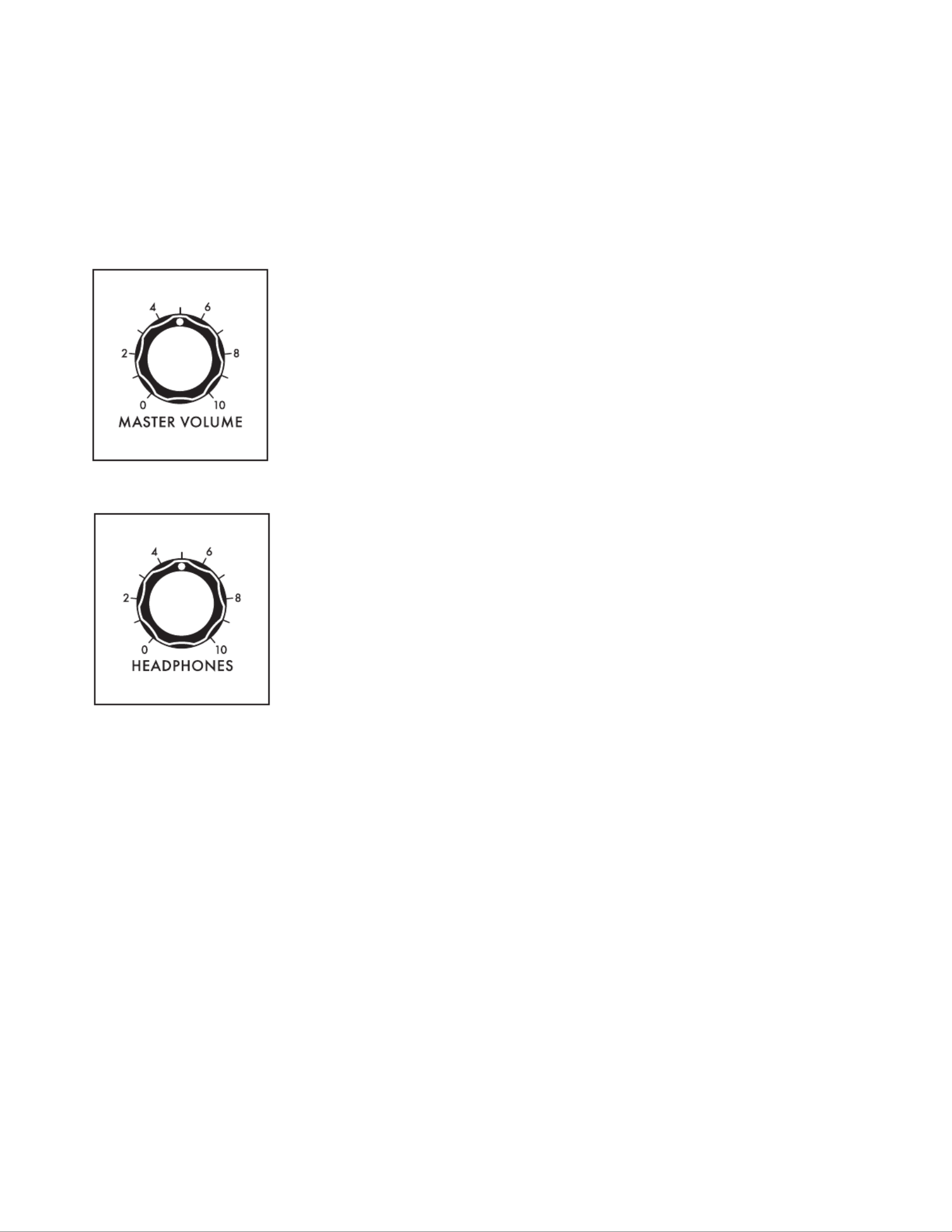
53
OUTPUT
The Output module contains two volume knobs, one to control the (MASTER VOLUME MAIN L/R
outputs), and one to control the output level. Each knob functions independently; HEADPHONES
turning the MASTER VOLUME down and the HEADPHONES level up allows Moog One settings and
sounds to be cued up, or auditioned privately without the need to change any external mixer settings
or connections. The MASTER VOLUME and HEADPHONES knobs are global for the entire Moog One.
Unlike every other knob on the Front Panel, these knobs always display their true value in a “what you
see is what you get” manner.
MASTER VOLUME (0 to 10)
The MASTER VOLUME knob controls the output level of MAIN L/R
Moog One. Higher values will have a higher volume level.
HEADPHONES (0 0)to 1
Moog One provides two identical headphone jacks, located on the
front edge of the Left Hand Controller panel. This HEADPHONES
knob controls the volume level of the HEADPHONES jacks, which
are not affected by the MASTER VOLUME knob. This allows you to
check or tweak a Preset with headphones on stage without allowing
the audience to hear it until you’re ready to turn up the MASTER
VOLUME knob.
OUTPUT MORE PAGE
Pressing the triangular button in the upper right corner of the module will reveal a MORE OUTPUT
second level of parameters that can be accessed and modied using the interactive portion of the
Center Console. These additional parameters are displayed in the bottom portion of the screen. The
left pane displays output assignments for each Synth and for each of the EXT. INPUT jacks, as well as
the volume level of each output. The right pane shows the current value of the Front Panel hardware
parameters for this module. Tweaking these panel controls will update their values here.
The MORE parameters of the global OUTPUT module designate the routing for each Synth in the
current Preset. Output Routing for the Insert channels is one-to-one, meaning each Synth can only be
assigned to one Insert at a time, and each Insert can only host one Synth at a time.
NOTE: Pressing the (now) illuminated MORE button will exit the MORE page and recall the screen.HOME
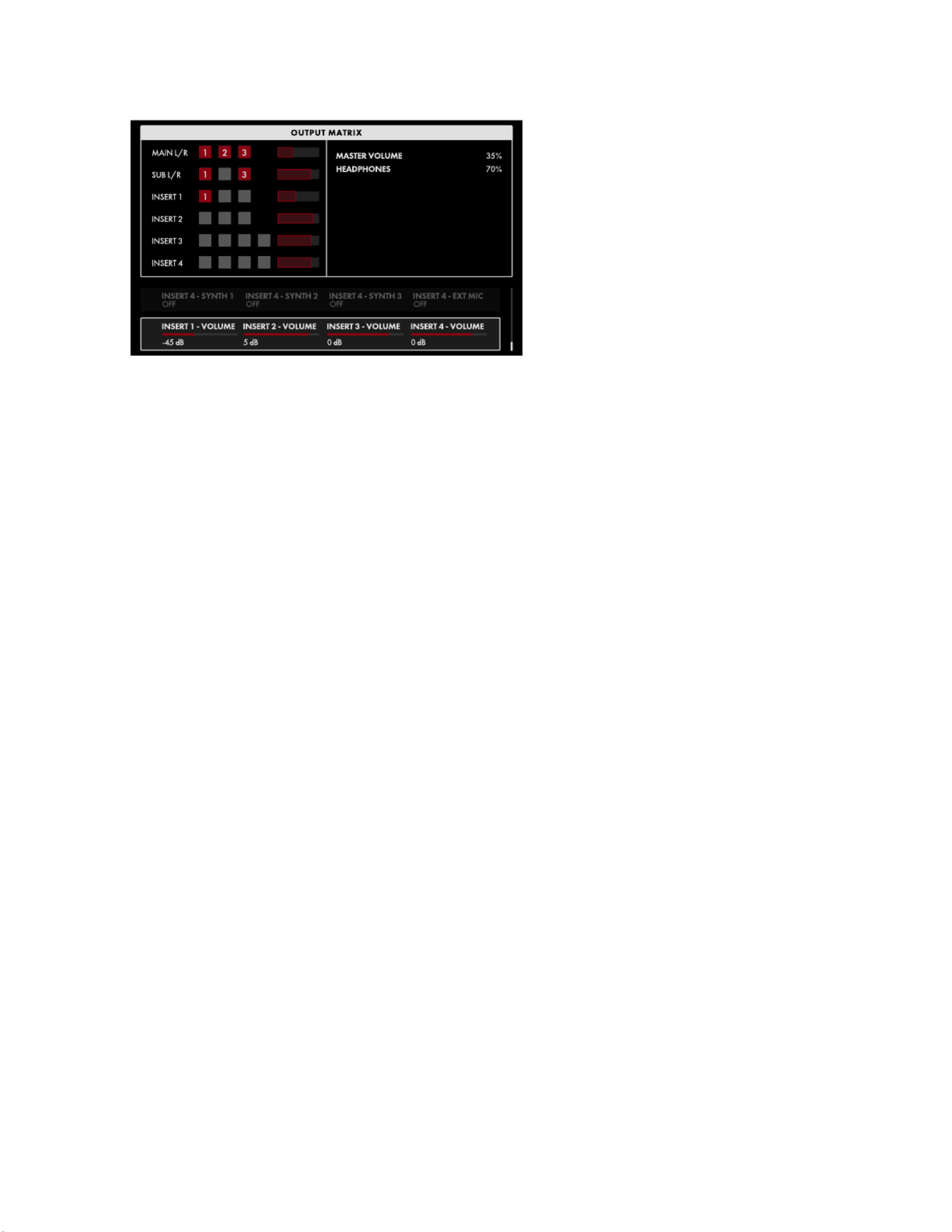
54
OUTPUT (Continued)
The onscreen page parameters are MORE
edited using the four Soft Knobs below
the screen.
CHANGING THE VALUE
Rotate the Soft Knob below the parameter
name to change its value. In some cases,
the Soft Knob simply turns a function on
or off. In other cases, the Soft Knob may
choose from a list of values or settings,
and in other cases, the Soft Knob is
dialing in a value – either absolute or a
percentage.
SELECTING A ROW
The scroll bar at the right edge indicates the current row. Rotate the Master Encoder to the right to
highlight the next row of parameters. Rotating the Master Encoder to the left will select a previous row.
Again, rotate the Soft Knob below the parameter to change its value.
MAIN - SYNTH 1 (OFF, ON)
Setting this parameter to On will route Synth 1 to the Outputs.MAIN L and MAIN R
MAIN - SYNTH 2 (OFF, ON)
Setting this parameter to On will route Synth 2 to the Outputs.MAIN L and MAIN R
MAIN - SYNTH 3 (OFF, ON)
Setting this parameter to On will route Synth 3 to the Outputs.MAIN L and MAIN R
SUB - SYNTH 1 (OFF, ON)
Setting this parameter to On will route Synth 1 to the Outputs on the Rear Panel.SUB L and SUB R
SUB - SYNTH 2 (OFF, ON)
Setting this parameter to On will route Synth 2 to the Outputs on the Rear Panel.SUB L and SUB R
SUB - SYNTH 3 (OFF, ON)
Setting this parameter to On will route Synth 3 to the Outputs on the Rear Panel.SUB L and SUB R
SUB VOLUME (-96 dB to 0 dB to +22 dB)
This parameter allows the output volume of the and SUB L SUB R Outputs to be set independently of
the and MAIN L MAIN R Outputs.
INSERT 1 - SYNTH 1 (OFF, ON)
Setting this parameter to On will route Synth 1 to the INSERT 1 buss.
INSERT 1 - SYNTH 2 (OFF, ON)
Setting this parameter to On will route Synth 2 to the INSERT 1 buss.
INSERT 1 - SYNTH 3 (OFF, ON)
Setting this parameter to On will route Synth 3 to the INSERT 1 buss.

55
OUTPUT (Continued)
INSERT 2 - SYNTH 1 (OFF, ON)
Setting this parameter to On will route Synth 1 to the INSERT 2 buss.
INSERT 2 - SYNTH 2 (OFF, ON)
Setting this parameter to On will route Synth 2 to the INSERT 2 buss.
INSERT 2 - SYNTH 3 (OFF, ON)
Setting this parameter to On will route Synth 3 to the INSERT 2 buss.
INSERT 3 - SYNTH 1 (OFF, ON)
Setting this parameter to On will route Synth 1 to the INSERT 3 buss.
INSERT 3 - SYNTH 2 (OFF, ON)
Setting this parameter to On will route Synth 2 to the INSERT 3 buss.
INSERT 3 - SYNTH 3 (OFF, ON)
Setting this parameter to On will route Synth 3 to the INSERT 3 buss.
INSERT 3 - EXT 1/4 (OFF, ON)
Setting this parameter to On will route an audio signal arriving at the
EXT INPUT 1/4” jack to the INSERT 3 buss.
INSERT 4 - SYNTH 1 (OFF, ON)
Setting this parameter to On will route Synth 1 to the INSERT 4 buss.
INSERT 4 - SYNTH 2 (OFF, ON)
Setting this parameter to On will route Synth 2 to the INSERT 4 buss.
INSERT 4 - SYNTH 3 (OFF, ON)
Setting this parameter to On will route Synth 3 to the INSERT 4 buss.
INSERT 4 - EXT XLR (OFF, ON)
Setting this parameter to On will route an audio signal arriving at the
EXT INPUT XLR jack to the INSERT 4 buss.
INSERT 1 - VOLUME (-96 dB to 0 dB to +22 dB)
This parameter allows the volume of the INSERT 1 Output to be set independently.
INSERT 2 - VOLUME (-96 dB to 0 dB to +22 dB)
This parameter allows the volume of the INSERT 2 Output to be set independently.
INSERT 3 - VOLUME (-96 dB to 0 dB to +22 dB)
This parameter allows the volume of the INSERT 3 Output to be set independently.
INSERT 4 - VOLUME (-96 dB to 0 dB to +22 dB)
This parameter allows the volume of the INSERT 4 Output to be set independently.

56
OUTPUT (Continued)
UNDERSTANDING INSERTS
Inserts are unique in that they can function as both outputs and inputs at the same time. As outputs,
they provide a way of allowing each Synth to have its own dedicated output - either for recording and
monitoring purposes, or to independently access an external effect processor such as a stereo chorus
unit. The inserts also provide an input path, or return, from such an external processor. The monaural
output from an external processor is returned to the same insert jack it was sent from, using a 1/4” TRS
to dual 1/4” TS insert cable. For an external processor with a monaural input and a stereo output, Moog
One can receive the return signals using an adjacent pair of inserts. Odd numbered inserts ( ) merge 1 3,
the return signal to the , MAIN L buss, and even numbered insert (2 4) merge the return signal to the
MAIN R bus. In this way, a monaural signal sent to an external processor can return in stereo using a
pair of adjacent insert points ( ). So the monaural signal sent via 1 2 3 4 & or & INSERT 1 can be returned
in stereo using and . Further, these adjacent pairs are normalled, so that if nothing INSERT 1 INSERT 2
is connected to , the monaural return signal arriving at will be applied to both the INSERT 2 INSERT 1
MAIN L MAIN R and busses. The same scenario applies to INSERT 3 and INSERT 4.
Technically, each of the four inserts relies on a single 1/4” TRS jack wired as both a send and a return.
The Tip of this Tip/Ring/Sleeve jack is wired as the Send; the signal is then returned to Moog One
via the Ring connection of the Tip/Ring/Sleeve jack. Most often, an insert jack will be used with a
Y-Conguration Insert Cable (1/4” TRS to dual 1/4” TS) to achieve this functionality.
NOTE: When active, the onboard Synth Effect is applied to each Synth before its signal reaches the
output (Tip) of the insert jack.
TIP: When using the INSERT jacks only as individual outputs, simply use a 1/4” TS cable and specify the
appropriate routings in the OUTPUT MORE page.

57
PERFORMANCE SET
A chosen Performance Set makes up to 64 Presets available with just a button press (or two) on the
Front Panel. This is a must for live performance, and can be equally useful for organizing sounds
at a session. Moog One contains a virtually unlimited number of Performance Sets, but only one
Performance Set can be active at any time. Choose a Preset from the active Performance Set by
pressing one of the 8 -BANK buttons (A H) and one of the 8 PRESET buttons ( ) on the Front 1 8-
Panel. Both of the buttons you selected will light to show the active Preset. When selecting a Preset
from within the current Bank, just press the appropriate PRESET button.
TIP: There is a SHOW BANK PREVIEW option available (SETTINGS / GLOBAL / HARDWARE
SETTINGS). When this function is On, pressing a BANK button will open a screen showing all of
the Presets assigned to that Bank.
NOTE: The Performance Set does not
itself provide storage of Presets; instead,
the Performance Set saves “pointers” that
direct Moog One to recall a specic Preset
from memory.
TIP: The active BANK (A - H) and PRESET
(1 - 8) buttons will light at full intensity;
unselected buttons will have a PRESET
softer light. If a button appears PRESET
dark (unlit), then no Preset has been
assigned to that location.
Performance Sets are stored by number. This provides a consistent order when browsing Performance
Sets, and also facilitates remote MIDI Program and Bank selection. In addition, each Performance Set
may be given a name, and text notes may be added as well. These notes can be quick reminders such as
“Set List for Trio Project” or “Lead Sounds for the Album Overdubbing Session,” etc. Any Preset may be
assigned to any Performance Set, and the same Preset may appear in multiple Performance Sets.
ASSIGNING THE CURRENT PRESET TO THE PERFORMANCE SET
The Performance Set BANK and PRESET buttons can also be used to assign the current Preset to the
active Performance Set. First, press the desired -BANK button (A H) if it is not already lit. Next, assign
the current preset to a Performance Set location by pressing and holding one of the PRESET buttons
( ) for about one second. The button will ash rapidly as conrmation.1 8- PRESET

58
PERFORMANCE SET (Continued)
PERFORMANCE SET MORE PAGES
Pressing the triangular button in the upper right corner of the MORE PERFORMANCE SET module
will open the CURRENT SET page. The additional and BROWSE SETS ARRANGE SETS pages can be
selected using the Soft Buttons above the screen. When in Arrange Sets, An EDIT soft button allows
editing of the Name and Notes for the current/selected set.
CURRENT SET
The CURRENT SET page provides
the name and number of the active
Performance Set under the SET heading,
The BANK heading shows which Bank
is selected, and the names of all of the
Presets in that Bank are shown under the
PRESETS heading; the current Preset is
highlighted. Turning the Master Encoder
selects the next (to the right) or previous
(to the left) Preset.
Holding SHIFT while turning the Master
Encoder allows the highlighted Preset to
be moved to a new location within the current Bank. Once the highlighted Preset is in its new location,
release the SHIFT button; all the other Presets in that Bank will be re-numbered accordingly.
NOTE: If a Preset not assigned to the current Performance Set was active before pressing the MORE
button, then Bank A of the current Performance Set will be selected, but no Preset will be highlighted.
The rst time you turn the Master Encoder, Preset 1 of the active Performance Set will be selected. After
that, the Master Encoder will load Presets normally.
BROWSE SETS
Use the BROWSE SETS Soft Button to
open this screen. The left pane shows a
list of all Performance Sets. The upper
right pane displays any descriptive
or performance notes that have been
added; the lower right pane shows the
timestamp data, indicating when the
Performance Set was last modied or
created. The current Performance Set is
highlighted.
LOADING A PERFORMANCE SET USING THE BROWSER
While the BROWSE SETS screen is open, rotate the Master Encoder to select and highlight
a different Performance Set; the Performance Set selected here will automatically load and
become the active Performance Set.
NOTE: Even when a new Performance Set has been selected, the active Preset will not change
until a Preset is selected from this new Performance Set.
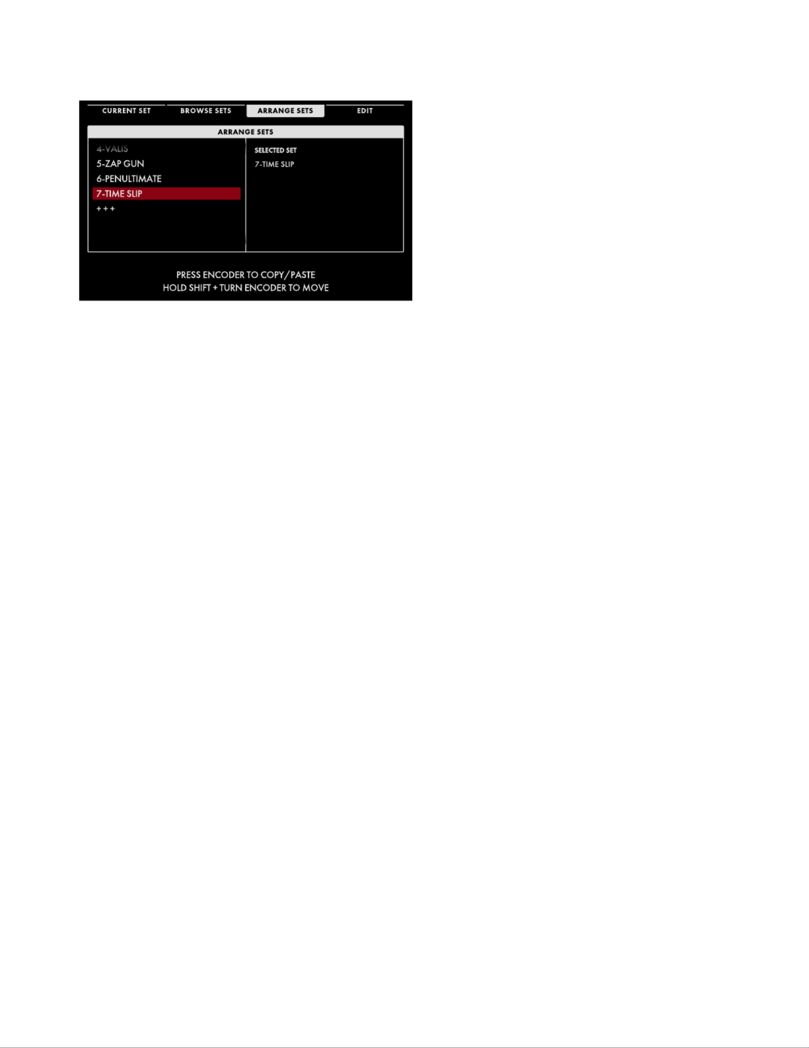
59
PERFORMANCE SET (Continued)
ARRANGE SETS
Use the ARRANGE SETS Soft Button to
open this screen. Here you can add, delete,
and rearrange Performance Sets. The
left pane shows a list of all Performance
Sets. The current Performance Set is
highlighted, and appears as the Selected
Set in the right pane.
MOVING A PERFORMANCE SET
Holding SHIFT while turning the Master Encoder allows the highlighted Performance Set to
be moved to a new location in the list. Once the highlighted Performance Set is in its new
location, release the SHIFT button.
COPYING A PERFORMANCE SET
Press down on the Master Encoder to create a copy of the highlighted Performance Set.
Turn the Master Encoder to scroll through the list of Performance Sets, then press down
on the Master Encoder to place the copied Performance Set in that location. The copied
Performance Set is placed between existing Performance Sets – no data is overwritten.
DELETING A PERFORMANCE SET
Once a Performance Set is highlighted, pressing the DELETE button on the Front Panel will
delete it. The other performance sets will move to ll the gap.
ADDING A PERFORMANCE SET
Use the Master Encoder to scroll to the bottom of the Performance Set list until the +++
indicator appears. Highlight this indicator, and the EDIT Soft Button above the screen will
change to . Pressing the ADD NEW ADD NEW Soft Button will allow you to enter a name for a
new, empty Performance Set. Finally, press the OK Soft Button to complete the process and
create your blank Performance Set.
EDITING A PERFORMANCE SET
The rightmost Soft Button above the screen is labeled (or EDIT ADD NEW, as described
above) -- pressing this button opens an editing window where you can edit the Name or
Notes for the currently selected set. When nished editing, press either the OK Soft Button to
save your changes, or the Soft Button to exit without saving changes.CANCEL

61
MASTER CLOCK (Continued)
TEMPO (0 to 10)
This knob sets the tempo for the Master Clock. Turn the knob TEMPO
to the left to slow down the Master Clock; turn the knob to the TEMPO
right to speed up the Master Clock. The available range is from 10 BPM
to 280 BPM. The LED above the knob will ash on each beat to TEMPO
visually indicate the tempo.
TAP
The TAP button allows the tempo value to be set by feel, as opposed
to a number. Tap the button a few times at the desired rate to set TAP
the tempo. The tempo is set based on the timing between taps. More
taps at a consistent rate will produce a more accurate tempo setting.
NUDGE (+ -) and
These buttons are used to perform minor tweaks to the tempo setting in
real time. Their function and operation is set using commands found in
the Master Clock MORE page.
MASTER CLOCK MORE PAGE
Pressing the triangular button in the upper right corner of the Master Clock module opens a MORE
second level of parameters that can be accessed and modied using the interactive portion of the
Center Console. The current tempo is displayed in the center of the screen and can be changed by
rotating the Master Encoder.
NOTE: Pressing the (now) illuminated button will exit the MORE MORE page and recall the screen.HOME

62
MASTER CLOCK MORE PAGE (Continued)
The onscreen MORE page parameters
are edited using the soft rotary encoders
below the screen.
CHANGING THE VALUE
Rotate the Soft Knob below the parameter
name to change its value. In some cases,
the Soft Knob simply turns a function on
or off. In other cases, the Soft Knob may
choose from a list of values or settings,
and in other cases, the Soft Knob is dialing
in a value – either an absolute value or a
percentage.
SWING AMOUNT (0% to 50% to 100%)
Swing changes the timing relationship between the on-beat and the off-beat. The on-beat is always
strictly aligned to the clock. Adding swing allows the off-beat to come in a touch later and be a bit
shorter, or to come in a bit early and hold a touch longer. Swing beats, shufes, and other rhythmic
variations can be created this way. Swing is expressed as a percentage measuring how much time the
on-beat occupies, relative to the total duration of an on-beat plus an off-beat.
Below the tempo value is a type of bar graph showing the amount of Swing being applied. In this bar
graph, each white box represents an on-beat, and each gray box represents the complementary off-
beat. As you rotate the Soft Knob to change the amount of Swing, the relationship between these two
boxes will change to indicate how Swing is being applied. In the center position (50%), no swing is
being applied to the beat.
NUDGE MODE (INCREMENT, BEND)
This parameter determines the behavior of the and buttons on the Front Panel.+ -
INCREMENT
In this mode, each press of the + button will increase the Master Clock tempo by 1 BPM,
and each press of the - button will decrease the tempo of the Master Clock by 1 BPM. While
holding the button in the Center Console, each press of the button will increase the SHIFT +
Master Clock tempo by 0.1 BPM, and each press of the - button will decrease the tempo of the
Master Clock by 0.1 BPM.
BEND
In this mode, holding the + button will momentarily increase the Master Clock tempo by 2
BPM until the button is released. Holding the button will momentarily decrease the Master -
Clock tempo by 2 BPM until the button is released. While holding the SHIFT button in the
Center Console, holding the + button will momentarily increase the Master Clock tempo by 1
BPM until the button is released. Holding the - button will momentarily decrease the Master
Clock tempo by 1 BPM until the button is released. When either button is released the tempo
returns to its original value. Borrowed from the DJ world, this technique is great for beat
matching on the y.
LOAD PRESET TEMPO (ON, OFF)
When this parameter is set to On, loading a Preset will also load the tempo that was saved with the
Preset. In this way, calling up a Preset will automatically call up the correct and saved tempo for your
performance. When this parameter is Off, the current tempo will be used.

63
VOICE ALLOCATION (HOLD/CHORD/POLYPHONY)
Moog One uses a number of sophisticated elements to make the most of the available voices. Grouped
together in one area of the Front Panel, these features include the button, the HOLD CHORD functions,
and the POLYPHONY module.
HOLD
The HOLD button behaves in much the same way as a sustain pedal –
but with a few important differences. When the button is set to HOLD
On (lit), notes being held when the button was pressed will continue to
sound. If new notes are added in a legato style – that is, they are played
while other notes are still held – these new notes will be added to the
current stack of held notes. If new notes are added in a non-legato
fashion, where all of the notes have been released before the new notes
are played, the previous notes will stop sounding, and these new non-
legato notes will take their place. The button also acts as a latch HOLD
for the Arpeggiator.
NOTE: The HOLD button and the Sustain pedal can interact in the following way. If the HOLD button
is On and the Sustain pedal is also being held (On) then playing new non-legato notes will not clear the
previously held notes, they will simply be added to the sustained notes.
CHORD
Using the CHORD function – often called Chord Memory – allows multiple
notes to be stacked on a single key. In turn, each key will play also play a
stack of notes pitched at those same intervals. If the CHORD function is
set to a major triad, every individual key will play a major triad – with the
root being the pitch of the key itself. The choice of notes is totally up to
the user; it need not be a traditional chord at all.
TIP: The CHORD function offers a massive sound with very little effort, but
it also can quickly chew up polyphony. Remember that, with the Moog One
three oscillator architecture, you can also set up the Oscillators’ tunings to
play a major triad on each key while using only a single voice. That said,
there are many situations where the function is the way to goCHORD .
In the Moog One architecture, the CHORD function is the last module to be presented with note values.
The priority runs from [Notes played on the keyboard or via MIDI] to [notes generated by the Arpeggiator]
to [interval values saved with the Chord Memory]. This means that every note generated by the
Arpeggiator (or Sequencer, for that matter) is in turn fed into the CHORD function, with every arpeggiated
or sequenced note playing back as a chord. This makes the Chord feature even more powerful.
USING THE CHORD FUNCTION
Press the LEARN button to turn on the Chord Learn function (the button will light). To create a LEARN
chord, play any series of notes. The rst note you play will clear the Chord Learn function and will also
set the root note. When you are nished adding notes to your chord, press the LEARN button a second
time (the button will go dark) to turn the Chord Learn function off. Now, when the CHORD button is
turned On, each note will play a transposed version of that chord. One of the Moog One Global settings
is the Silent Learn option, which mutes the active synth while the Chord Learn function is On, allowing
the chord to be entered in a live venue without the audience hearing this take place. The ip side is that
the performer can’t hear it either. Both the chord created using the LEARN button and the state of the
CHORD button (On/Off) are saved per Synth.
TIP: When entering a chord, Moog One will recognize the rst note entered as the Root note; in this way
you can enter a chord using an inversion, and it will still be transposed correctly.

64
POLYPHONY
It is polyphony that allows Moog One to play multiple keys at the same time and have them all sound.
All polyphonic synthesizers – including Moog One – have a nite number of voices. This module
controls the ways to maximize performance by allocating voices effectively. But it’s not only about
polyphony. Monophonic, or single-note-at-a-time synthesizer playing, has a style all its own, and
parameters found here can make the most of those performances as well.
MONO (ON/LIT, OFF/UNLIT)
This button acts as a toggle, switching the active Synth between the
Monophonic mode (lit) and Polyphonic mode (unlit). Each mode has
additional parameters to dene behavior, voice allocation, etc.
UNISON (ON/LIT, OFF/UNLIT)
When UNISON button is lit, all of the available voices will play whenever
possible, dividing the total number of voices by the number of keys being
played, and stacking themselves accordingly. These stacked analog
voices can add fullness and depth. For example, if the current Synth is set
to a POLY COUNT ( page parameter) of eight voices, playing one MORE
note will sound eight stacked voices. Adding a second note will reallocate
four voices to a Unison stack on the new note, and four voices will
continue to play in a Unison stack on the already held note, etc.
NOTE: Use the UNISON COUNT parameter in the Polyphony MORE page to limit and specify the number
of voices being stacked, per note.
DETUNE (0 10)to
When the UNISON button is On/Lit, rotating this knob to the right will apply higher levels of detuning
to the stacked Unison voices. The available voices are detuned symmetrically on either side of the
original pitch, keeping it as the tonal center of the stacked voices. Not all voices are detuned by the
same amount, increasing the fullness of the effect. This knob sets the maximum derivation from the
original pitch.
NOTE: The Front Panel shows a value range of 0 to 10. Opening the Polyphony MORE page will open a
graphic image in the left pane of the Center Console display, showing this value being changed from
0% to 100%.

65
POLYPHONY MORE PAGE
Pressing the triangular button in the upper right corner of the MORE POLYPHONY module will reveal
a second level of parameters than can be accessed and modied using the interactive portion of the
Center Console. The left pane shows the width of the Detune Amount, as determined by the DETUNE
knob on the Front Panel. The right pane shows the current values of the Front Panel parameters
for this module. Tweaking these panel controls will update their values here. The additional MORE
parameters are displayed in the bottom portion of the screen.
NOTE: Pressing the (now) illuminated MORE button will exit the MORE page and recall the screen.HOME
These onscreen parameters are accessed
using the Master Encoder and the four
Soft Knobs below the screen.
CHANGING THE VALUE
Simply rotate the Soft Knob below the
parameter name to change its value. In
some cases, the Soft Knob simply turns a
function on or off. In other cases, it may
choose from a list of values or settings,
and in other cases, the Soft Knob is
dialing in a value – either absolute or a
percentage
SELECTING A ROW
Rotate the Master Encoder to the right to highlight the next row of parameters. Rotating the Master
Encoder to the left will select a previous row. Again, rotate the Soft Knob below the parameter to
change its value.
UNISON COUNT (MINIMUM = 2; MAXIMUM = POLY COUNT VALUE)
The number of voices allocated here will determine the depth and fatness of the Unison effect. The
minimum number of voices is 2, the maximum limit is the number of voices set by the POLY COUNT
parameter (see below). When the MONO mode is selected on the Front Panel, all of the voices
specied here will be stacked in Unison on that one note. However, when the MONO mode is set to Off,
Moog One will continue to allocate Unison voice-stacking in the mode. On a 16-voice Moog One, POLY
you could set the to 4, and up to four notes could be played with a four-voice Unison UNISON COUNT
stack. Conversely, if both the UNISON COUNT and the POLY COUNT are set to 16, then the rst note
played would be allocated the full 16 voices; when a second note is added, 8 voices would be allocated
to each, etc.
POLY COUNT (MINIMUM = 2; MAXIMUM = AVAILABLE HARDWARE VOICES)
Here you can specify the maximum number of voices allocated to the active Synth while in the
POLY mode ( button is Off). When performing using a Preset that may play multiple Synths MONO
simultaneously (layers, splits, etc.), limiting the POLY COUNT can improve how voices are effectively
shared and allocated among the Synths.
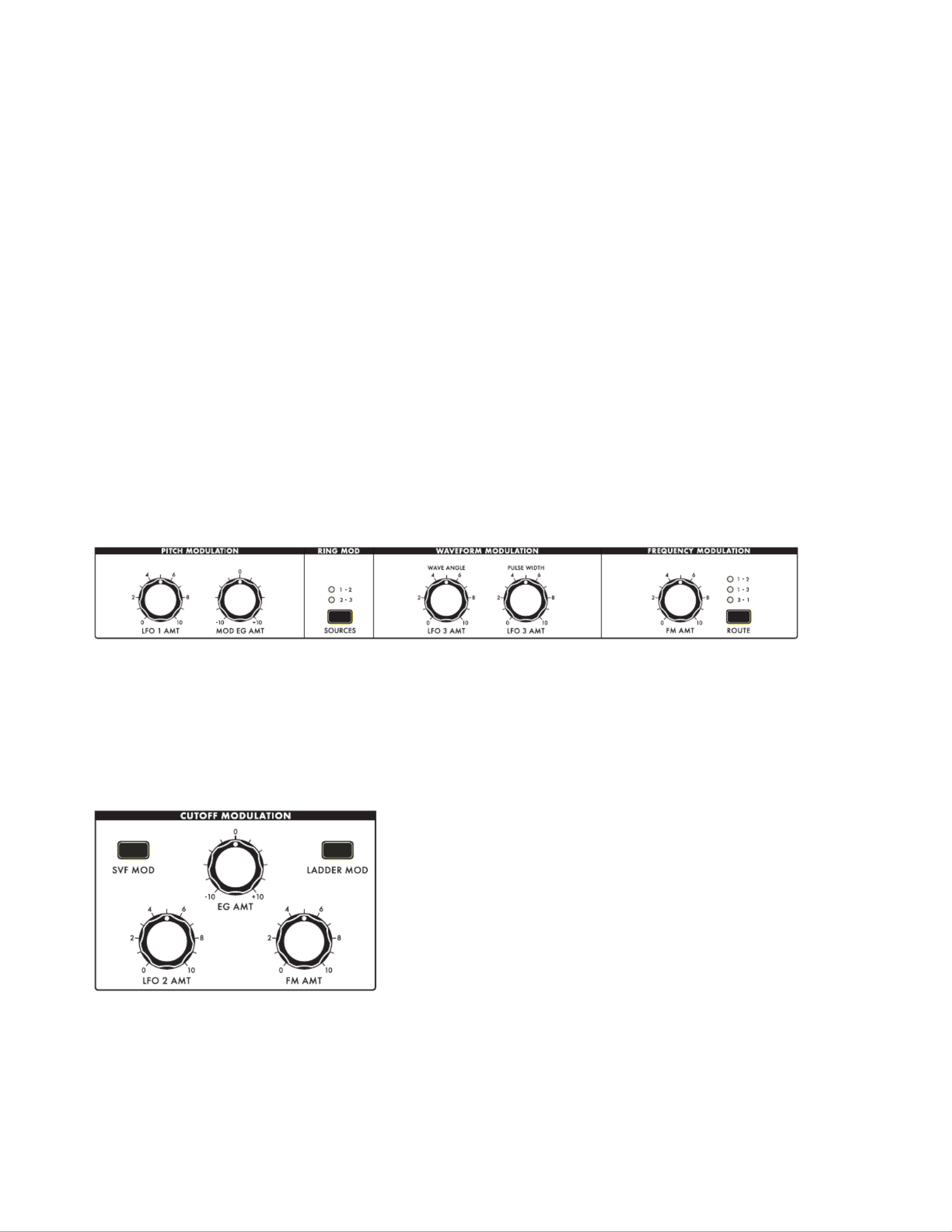
67
MODULATION
In basic terms, modulation allows a control signal from one module to inuence the value of a
parameter in another module. A modulation path needs both a source and a destination. In a truly
modular world, each modulation pathway is created by connecting a separate patch cord from the
modulation source to the destination – often side stepping along the way to invert the value, to
add a controller, or to use a multiple (Mult.) jack to carry the signal to multiple destinations. Cyclic
modulation sources (such as LFOs) generate excellent control signals for adding vibrato and tremolo.
Envelopes can deliver multi-segment control signals that evolve to shape a sound over time. This is
the crux of modular synthesis. Moog One can create, catalog, save, and maintain countless modulation
pathways, adding greatly to the precision, depth, and animation of the nal sound.
Moog One employs three basic means for addressing modulation: Hard-Wired; Quick Assign; and the
unparalleled Modulation Matrix.
HARD-WIRED MODULATION
Some modulation pathways are so common and well established in the world of synthesis and sound
design that Moog One offers their immediate control using dedicated hardware. These hard-wired
modulation controls appear along the bottom portion of the individual Oscillator modules, and in the
lower portion of the Filter modules. These shortcuts should in no way be seen as limiting to the user;
any of these modulation sources and destinations can also be connected in new and different ways
using the expansive Modulation Matrix.
HARD-WIRED OSCILLATOR COMMON MODULATION PARAMETERS
Here, the Pitch Modulation and Waveform Modulation parameters are applied to all Oscillators equally.
Selecting the Ring Modulation sources and choosing a Frequency Modulation routing are
also performed using the controls found in this section.
HARD-WIRED FILTER COMMON MODULATION PARAMETERS
These knobs control the amount of Cutoff Frequency
modulation being applied by these sources. The amounts
can be the same for both lters, or they can be adjusted
separately. When the SVF MOD button is lit, these knobs
can be used to tweak the modulation amounts being
applied to the State Variable Filter. When the LADDER
MOD button is lit, these knobs can be used to tweak the
modulation amounts being applied to the Ladder Filter.
When both the button and the SVF MOD LADDER MOD
button, tweaking these knobs will affect both lters
equally. The specic values of these parameters can be
seen in the right pane of the Filter MORE page.
NOTE: Regardless of which buttons - SVF MOD and/or LADDER MOD - are lit or unlit, the modulation
amounts for each lter, specied in the Filter MORE page, are being applied. The buttons work only to
select which lter(s) will be affected by further tweaking of these knobs.
The functions of these modulation controls are discussed in the Oscillator Common Parameters and
Filter Common Parameters sections of this manual.
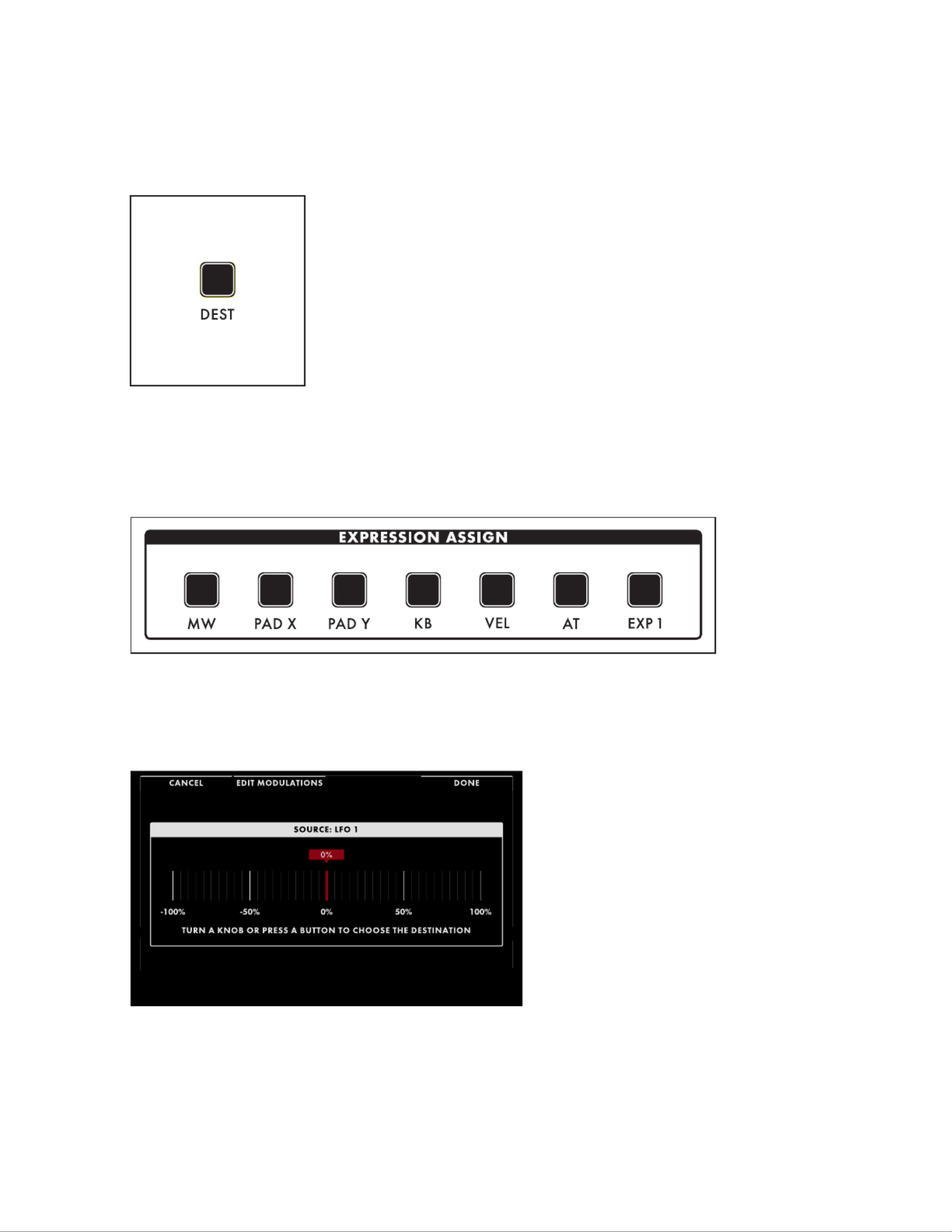
68
MODULATION (Continued)
QUICK ASSIGN MODULATION
Specic modulation sources and modulation expression controllers can be assigned on the y.
DEST
Pressing the DEST (Destination) button found in the lower right corner
of any Low Frequency Oscillator (LFOs 1, 2, 3, or 4) or in the lower right
corner of any EG (Filter Envelope, Amplitude Envelope, or Modulation
Envelope) will instantly create a new modulation pathway using that
LFO or EG as the source.
This same method of modulation routing is available by pressing one of the seven EXPRESSION
ASSIGN buttons at the bottom edge of the Center Console, which similarly assign a controller to a
specic modulation destination.
Once a button has been pressed, the Quick Assign modulation screen DEST or an EXPRESSION ASSIGN
will open in the Center Console. In this example, LFO 1 was the chosen as the modulation source.
The destination will be assigned
automatically to the rst hardware
parameter that is touched or operated. In
this example, Oscillator 2 Frequency has
been chosen as the modulation destination.
As the destination parameter knob is
turned, the value in the display will change
to show the depth of the modulation effect
being applied.
NOTE: This rotating of the destination parameter’s knob to set the depth of the modulation effect does not
alter the saved value of the parameter.
TIP: If the rst parameter operated was not the intended destination, you can press the DEST or
EXPRESSION ASSIGN button again to return to the “CHOOSE THE DESTINATION” screen.

69
MODULATION (Continued)
Four Soft Buttons are labelled at the top of
the screen.
CANCEL
Pressing the CANCEL Soft Button will exit
the Quick Assign window without saving
the new modulation path.
EDIT MODULATIONS
Pressing the EDIT MODULATIONS Soft
Button opens up a special case of the
Modulation Matrix screen that is ltered
by source, showing only the modulation
paths that have the same source as this
newly created path; again in this case, LFO
1. Navigating inside the Modulation Matrix is
covered extensively in the next section.
ADD DESTINATION
Pressing the ADD DESTINATION Soft Button saves the current modulation (same as the DONE
button) and returns to the initial Quick Assign screen, where an additional destination for the
same modulation source may be chosen simply by touching another hardware knob or button.
DONE
Pressing the DONE Soft Button will exit the Quick Assign window while saving the new
modulation path.

70
MODULATION (Continued)
MODULATION MATRIX
The Modulation Matrix is the nexus for all
modulation paths assigned to the active
Synth. This includes assignments made
here, and those made using the Quick
Assign method; they all are part of one
Modulation Matrix. Pressing the MOD
button in the Center Console opens the
Modulation Matrix screen.
Each modulation path is placed in a
numbered slot for ease of access and
editing. Rotate the Master Encoder
to select a modulation slot. When a
modulation path has been established, the dening parameters of the modulation path will appear in the
slot. If no modulation path has been established in the selected slot, the + + + + indicators will show that
the slot is ready to hold a new modulation path.
The parameters for the selected modulation path appear in two rows. The active row will appear in
white; the other row will be grayed out. To toggle between the two rows in the selected slot, press
down on the Master Encoder. Regardless of which row is active, the modulation path parameters are
edited using the four Soft Knobs at the bottom of the screen, and the three Soft Buttons up top.
EDITING OR CREATING A NEW
MODULATION PATH
To edit an existing modulation path, select
and highlight the appropriate modulation
slot by rotating the Master Encoder. Use
the Soft Knobs to edit an existing value. To
create a new path inside the Modulation
Matrix, rotate the Master Encoder to select
the rst available empty (unassigned) slot.
Use the Soft Knobs to assign a source,
destination, etc. to the new modulation path.
In either case, press down on the Master
Encoder to toggle between top row and
bottom row parameters.
TIP: As an aid to programming, the far left DISABLE/ENABLE Soft Button acts as a toggle, allowing the
selected modulation path to be quickly disabled or enabled, without the need to permanently delete the
path. When a modulation path is in the disabled state, it will appear grayed-out.
SOURCE
TOP ROW: Source Parameter Name
BOTTOM ROW: Source Parameter Value: -300% to 0 to +300%
The rst step is to select a modulation source. Be sure the top row is selected and use the SOURCE
Soft Knob to choose the modulation source. Next, press the Master Encoder to access the Bottom Row
parameters and specify a value to indicate the strength of the modulating signal. When the value is set
to 0, the modulation strength is also zero (no effect). Positive values will produce normal modulation;
negative values will produce modulation with an inverted signal.
NOTE: Although the Source Amount appears before the Controller Amount and Transform Amount
values; this value is actually applied after the control signal leaves the Controller and the Transform, but
before it reaches the destination. This allows the Controller/Transform to receive the modulation signal
at full strength for more accurate processing. Then the Source Amount is applied to set the level.

71
MODULATION (Continued)
CONTROLLER
TOP ROW: Controller
BOTTOM ROW: Controller Value: -100 to 0 to +100%
The modulation source can be applied directly to the modulation destination, or the amount of
modulation can be articulated using an assignable controller such as Aftertouch. The amount of
modulation can also be attenuated by using another mod source as a controller, such as an LFO or
EG. Use the Controller Soft Knob to select a controller, or simply select NONE. Controller Amount
determines how strongly the Controller affects the amount of modulation. When the Controller
Amount is set to 0, the value of the selected controller has no effect on the modulation strength. If the
Controller Amount is positive, then high Controller values create stronger modulation effects while
low Controller values reduce the amount of modulation. If the Controller Amount is negative, then the
effect of the Controller is reversed (a low Controller value allows more modulation to come through,
while increasing the Controller value attenuates the strength of modulation). If no Source is selected
but a Controller is assigned, then the Controller behaves like a Source and the Controller Amount
behaves as described above for the Source Amount.
TRANSFORM
Placing a Transform in the modulation path offers a number of ways to manipulate the value of the
modulation signal as it travels from the source to the destination. The Transform is selected using the
top parameter row; the value is entered using the bottom row parameters.
NONE
This is the default setting; no transform has been applied to the modulation path.
LIMIT LOW (0 100%)to
This Transform articially sets a lower limit on the value of the control signal. Values above
this low limit are played normally. Values below the low limit will be output using the value of
the low limit setting.
LIMIT HIGH (0 100%)to
This Transform articially sets an upper limit on the value of the control signal. Values below
this high limit are played normally. Values above the high limit will be output using the value of
the high limit setting.
SQUARED (FIXED)
The value of the Transform output is equal to the input value multiplied by itself, or squared.
CUBED (FIXED)
The value of the Transform output is equal to the input value multiplied by itself twice, or cubed.
DESTINATION
TOP ROW: Destination Module Name
BOTTOM ROW: Destination Parameter Name
The Destination species the parameter that will ultimately be controlled by this modulation path. The
list of modulation destinations is extensive. To make it easier to select a destination quickly, the top
row parameter will select the Moog One Module, the bottom row parameter will choose the destination
parameter from within that module.
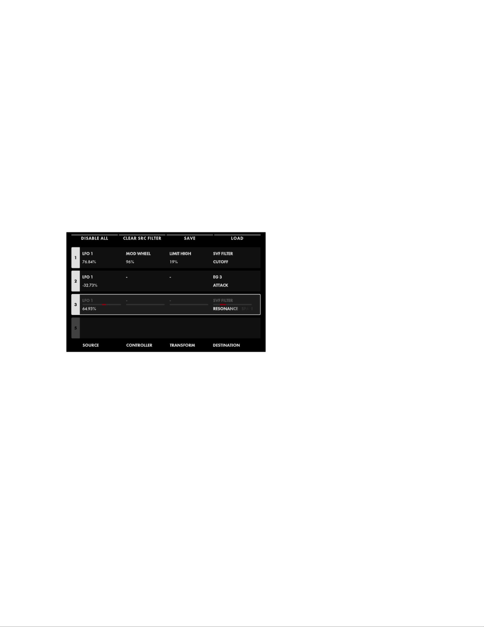
72
MODULATION (Continued)
DELETING A MODULATION PATH
To delete an existing modulation path, select the appropriate modulation slot by rotating the Master
Encoder and press the DELETE button in Center Console. The modulation path will be deleted, and the
existing modulation paths residing in higher numbered slots numbers will move to ll the gap. So if the
modulation path in slot 4 is deleted, the path that was in slot 5 will become the new number 4, etc.
FILTERING THE MODULATION LIST BY SOURCE OR DESTINATION
As the number of modulation paths within a specic Modulation Matrix expands, ltering the list
by modulation source or modulation destination can make it easier to nd and edit a particular
modulation path by displaying an abridged list. When the Modulation Matrix is opened in this manner,
the second Soft Button from the left (CLEAR SRC FILTER / CLEAR DEST FILTER) can be pressed to
clear any ltering of the Modulation Matrix list.
TIP: Notice that when modulation paths appear in the ltered list, they retain their existing slot numbers,
which can also make it easy to nd and reference them in the future.
FILTERING BY SOURCE
Holding the SHIFT button while pressing
any one of the DEST buttons on the Front
Panel (LFOs, EGs) will open the Modulation
Matrix, but showing only the modulation
paths using that module as a source. In the
example above, the SHIFT button was held
while the LFO 1 DEST button was selected,
and only the modulation paths using LFO 1
as a modulation source are shown. Pressing
the CLEAR SRC FILTER Soft Button will
clear the source lter, and all modulation
paths in the Modulation Matrix will be
displayed.
FILTERING BY DESTINATION
Holding the SHIFT button while pressing any one of the MORE buttons on the Front Panel
(OSCS, FILTERS, etc.) will open the Modulation Matrix, but showing only the modulation paths
whose destination is included in the selected module. Pressing the CLEAR DEST FILTER Soft
Button will clear the destination lter, and all modulation paths in the Modulation Matrix will
be displayed.
TIP: Be aware that using this ltering technique will only show a partial list of all modulation
pathways. Remember to press the second Soft Button from the left (CLEAR SRC FILTER /
CLEAR DEST FILTER) to clear any ltering of the Modulation Matrix list.

73
MODULATION (Continued)
SAVING AND LOADING A MODULATION MATRIX
Once a complete Modulation Matrix has been created, it can be saved for future use. When a Modulation
Matrix is recalled, it can be used as is, or edited and re-saved under a new name, without having to
rebuild the entire Modulation Matrix from scratch. This way, if there are particular routings that you are
fond of using, these settings can be kept readily at hand as a saved Modulation Matrix preset.
SAVING A MODULATION MATRIX
Pressing the SAVE Soft Button will open
the Save Modulation Matrix Preset screen.
The four Soft Buttons across the top are
NAME, NOTES, OK, and CANCEL.
When the screen opens, the SAVE NAME
Soft Button will already be selected, and
the screen prompt will ask you to name
the current Modulation Matrix.
Once you have entered a name for the Modulation Matrix, you can also enter any optional performance
notes using the same method. These notes can be quick reminders or application cues, such as “Uses
staggered and sync’d LFOs” or “this is the one Gerry created during the studio session” etc. Press the
NOTES Soft Button and follow the screen prompts. After naming the Modulation Matrix and adding
any notes, press the OK Soft Button to save the Modulation Matrix, or press the Soft Button CANCEL
to exit the Modulation Matrix screen without saving.SAVE
ENTERING TEXT
Moog One allows you to enter names and text directly from the keyboard. The white keys (naturals)
enter the characters; certain black keys (accidentals) have specic functions.
• Keys C#1 - D#2 select the character set.
• Key F#4 removes the current name and randomly generates a new name.
• Key G#4 clears all the characters in the screen.
• Key A#4 deletes the character to the left of the cursor.
• Keys C#5 and D#5, respectively, change the character immediately preceding the cursor to the
previous or next symbol in the current character set, changing an M to an L or an N, for example with a
single key press.
• Keys F#5 and G#5 move the cursor left or right, respectively.
• Key A#5 adds a space.
NOTE: The note numbers given above relate to the onscreen keyboard, and do not reect the keys’
actual MIDI Note numbers, etc.
TIP: You can also enter text directly, using a standard USB keyboard connected to the Moog One
USB HOST port.

75
MODULATION (Continued)
MODULATION MATRIX APPENDICES
Here you can nd the complete list of all available Sources, Controllers, Transforms, and Destinations
that can be used to create a path in the Modulation Matrix.
SOURCES CONTROLLERS TRANSFORMS
NONE NONENONE
LFO 1 MOD WHEEL LIMIT LOW
LFO 2 PITCH WHEEL LIMIT HIGH
LFO 3 PAD X SQUARED
LFO 4 PAD Y CUBED
FILTER EG PAD PRESSURE
AMPLIFIER EG PAD GATE
MODULATION EG VELOCITY
NOISE EG AFTERTOUCH
MOD WHEEL KEY PITCH
PITCH WHEEL KB GATE
PAD X SUSTAIN
PAD Y EXP 1
PAD PRESSURE EXP 2
PAD GATE CV IN 1
VELOCITY CV IN 2
AFTERTOUCH FILTER EG
KEY PITCH AMPLIFIER EG
KB GATE MODULATION EG
SUSTAIN NOISE EG
EXP 1 LFO 1
EXP 2 LFO 2
CV IN 1 LFO 3
CV IN 2 LFO 4
RANDOM RANDOM
RANDOM BIPOLAR RANDOM BIPOLAR
CONSTANT CONSTANT

76
ALL OSCILLATORS NOISE EG 1
PITCH LFO 1 MOD COLOR MIX DELAY
PITCH EG MOD ATTACK ATTACK
TRIANGLE LFO 3 MOD SUSTAIN HOLD
PULSE LFO 3 MOD RELEASE DECAY
FM MOD MIXER SUSTAIN
PITCH OFFSET OSC 1 LEVEL RELEASE
OSCILLATOR 1 OSC 2 LEVEL TIME SCALE
FREQUENCY OSC 3 LEVEL EG 2
BEAT RMOD LEVEL DELAY
SAW NOISE LEVEL ATTACK
TRIANGLE EXT LEVEL HOLD
PULSE VCA DECAY
MIX LEVEL SUSTAIN
OSCILLATOR 2 PAN RELEASE
FREQUENCY FILTERS TIME SCALE
BEAT SVF/LADDER MIX EG 3
SAW SVF FILTER DELAY
TRIANGLE CUTOFF ATTACK
PULSE RESONANCE HOLD
MIX SPACING DECAY
OSCILLATOR 3 EG AMOUNT SUSTAIN
FREQUENCY RELEASELFO 2 AMOUNT
BEAT FM AMOUNT TIME SCALE
SAW LADDER FILTER
TRIANGLE CUTOFF
PULSE RESONANCE
MIX EG AMOUNT
LFO 2 AMOUNT
FM AMOUNT
MODULATION (Continued)
DESTINATIONS
77
LFO 1 LFO 3 LFO 4
RATE RATE RATE
RATE (SEMITONES) RATE (SEMITONES) RATE (SEMITONES)
VARIATION VARIATION VARIATION
DELAY DELAY DELAY
FADE IN TIME FADE IN TIME FADE IN TIME
FADE OUT TIME FADE OUT TIME FADE OUT TIME
LFO 2
RATE
RATE (SEMITONES)
VARIATION
DELAY
FADE IN TIME
FADE OUT TIME
MODULATION (Continued)
DESTINATIONS

78
ARPEGGIATOR
At its most basic level, an arpeggiator scans the notes being held down on the keyboard and plays
them one at a time in a cyclic and rhythmic fashion. This description doesn’t even begin to come
close to describing the Moog One Arpeggiator. Octave Order, Pendulum Mode, and Random patterns
allow this Arpeggiator to become an extra set of hands, create an electronic counterpoint, generate
cascades of notes, and to form the solid base of a rhythmic groove.
The Arpeggiator exists at the Synth level, and all Arpeggiator parameters are saved with their
respective Timbre as part of the Preset. In this way, a single Preset can have up to three active
Arpeggiators (one per Synth) at any time, each playing a different pattern, using a different sound,
and in a different zone on the keyboard. The Arpeggiators – along with the Sequencers, LFOs and EGs
– can be sync’d to the tempo of the Master Clock to create a unied rhythmic performance. Unlike a
sequencer, which is playing patterns of specic notes stored in memory, the Arpeggiator is generating
data in real time, based on the notes being played; it is a bit more interactive, and is always musically
related to the performance.
ON (ON/LIT, OFF/UNLIT)
This button turns the Arpeggiator of the active Synth On and Off.
RATE (0 10)to
The knob sets the speed of the Arpeggiator. The actual tempo RATE
value ranges from 10 BPM to 280 BPM. The Arpeggiator Rate can run
at an independent speed, or it can be synchronized to the Master Clock
using the parameters accessed in the Arpeggiator MORE page. The
RATE knob LED will ash at the current setting.
NOTE: If the Arpeggiator is sync’d to the Master Clock, then rotating the
RATE knob will select quantized clock divisions of the Master Clock. All of
the page.SYNC parameters are available in the Arpeggiator MORE
OCTAVE ORDER (ON/LIT, OFF/UNLIT)
Traditionally, when an arpeggiator is set to play over a multi-octave
range, all of the notes are played in the current octave, and then the
pattern is repeated an octave higher, etc. When the OCTAVE ORDER
switch is On, the Arpeggiator pattern will play the rst note in the
pattern in each octave, then the second note of the pattern repeated in
each octave, etc.
EXAMPLE: The notes in the pattern are a C Major triad (C, E, G) and the
OCTAVE OCTAVE button value is = (three). With 3 ORDER set to Off,
the pattern generated would be C1-E1-G1, C2-E2-G2, C3-E3-G3, etc. With
OCTAVE ORDER set to On, the pattern generated would be C1-C2-C3,
E1-E2-E3, G1-G2-G3, etc.

79
ARPEGGIATOR (Continued)
PENDULUM (ON/LIT, OFF/UNLIT)
Pendulum changes the way the pattern is repeated. When the
PENDULUM button is set to On, once the entire arpeggiator pattern has
played through, the Pendulum function will play the entire arpeggiator
pattern again in the reverse order, and then the pattern will play
again normally, etc. This back and forth motion is similar to that of a
pendulum. When the PENDULUM button is Off, the pattern plays in its
usual order.
TIP: While certain combinations of the Direction and Pattern parameters
may already exhibit this type of behavior, adding PENDULUM motion
when the Pattern parameter is set to Random or Order can be
particularly effective.
NOTE: The PENDULUM MODE parameter in the Arpeggiator MORE page affects the turnaround notes
at the beginning and the end of the pattern.
OCTAVE (1, 2, 3, 4)
Increasing the Octave value will cause the arpeggiator pattern to play
through once in the original octave, and then to repeat in successive
octaves pitched higher or lower than the original. Press the OCTAVE
button to cycle through the list of values; the corresponding LED will
light. The minimum value is = 1, which plays the pattern in its original
octave; the maximum value is = 4, which plays the pattern in its original
octave, then an octave higher/lower, then two octaves higher/lower,
and then three octaves higher/lower. The choice between higher and
lower is made using the DIRECTION button.
DIRECTION (UP, DOWN, UP/DOWN, DOWN/UP)
When multiple octaves are selected using the OCTAVE button,
this Direction parameter species whether these additional octaves
are higher (UP) or lower ( ) in pitch than the original octave. DOWN
Press the DIRECTION button to cycle through the list of values; the
corresponding LED will light. When UP/ is selected, the pattern DOWN
rst repeats in octaves pitched higher than the original, and then
reverses direction to play through the selected octaves to reach the
original pitch. When DOWN/UP is selected, the pattern rst repeats in
octaves pitched lower than the original, and then reverses direction to
play through the selected octaves to reach the original pitch.

80
ARPEGGIATOR (Continued)
PATTERN (UP, DOWN, ORDER, RANDOM)
It is this parameter that species the pattern in which the arpeggiated
notes are played.
UP
Notes are arpeggiated from the lowest pitch to the highest pitch.
DOWN
Notes are arpeggiated from the highest pitch to the lowest pitch.
ORDER
Notes are arpeggiated based on the order in which they were played.
TIP: In Order mode, a held key can be released and then immediately played again to change its order in
the pattern, creating a new feel and groove while performing.
RANDOM
Notes are arpeggiated in a random order.
NOTE: The page offers a choice between RANDOM MODE parameter found in the Arpeggiator MORE
both repeating and non-repeating Random patterns.
ARPEGGIATOR MORE PAGE
Pressing the associated triangular MORE button in the upper right corner of the Arpeggiator module
will reveal a second level of parameters that can be accessed and modied using the interactive
portion of the Center Console. These additional parameters are displayed in the bottom portion of
the screen. The right pane shows the current value of the Front Panel hardware parameters for this
module. Tweaking these panel controls will update their values here.
NOTE: Pressing the (now) illuminated MORE button will exit the page and recall the HOME screen.MORE
The onscreen MORE page parameters are
edited using the four Soft Knobs below
the screen.
CHANGING THE VALUE
Rotate the Soft Knob below the parameter
name to change its value. In some cases,
the Soft Knob simply turns a function on
or off. In other cases, it may choose from
a list of values or settings, and in other
cases, the Soft Knob is dialing in a value –
either absolute or a percentage.
SELECTING A ROW
The scroll bar at the right edge indicates the current row. Rotate the Master Encoder to the right to
highlight the next row of parameters. Rotating the Master Encoder to the left will select a previous row.
Again, rotate the Soft Knob below the parameter to change its value.

81
ARPEGGIATOR (Continued)
SYNC (OFF, ON)
When SYNC is Off, the Arpeggiator is free to run at its own speed and clock rate. When is On, the SYNC
Arpeggiator and Master Clock are synchronized, and the Master Clock determines the Arpeggiator tempo.
NOTE: When is selected here, rotating the Arpeggiator SYNC RATE knob on the Front Panel will select
quantized clock divisions (see below) of the Master Clock.
CLOCK DIVISION (4, 2, 1, 1/2, 1/4, 1/8, 1/16, 1/32)
When sync’d, the Master Clock provides a tempo base; divisions of that Master Clock are used to set
the Arpeggiator speed. Changing the CLOCK DIVISION parameter species the timing in terms of
quarter-note beats.
CLOCK TIMING (STRAIGHT, DOTTED, TRIPLET)
When sync’d, Clock Timing provides a further modication of the step duration, allowing for a wider
selection of note timings relative to the Master Clock tempo.
STRAIGHT
The timing of each note is played as specied by the Clock Division.
DOTTED
The timing of each note is modied to play as a dotted note, or at 1.5 x the value specied by the
CLOCK DIVISION parameter.
TRIPLET
The timing of each note is modied to play as if it were one note in a triplet, or at 2/3rds of
the value specied by the CLOCK DIVISION parameter.
GATE LENGTH (1% to 100%)
Adjusting the GATE LENGTH parameter changes the duration of each arpeggiated note in the pattern.
Lower values will be more percussive and abrupt, higher values will be more owing and legato.
FOLLOW SWING (OFF, ON)
The Master Clock includes parameters related to adding swing to the beat. When sync’d to the Master Clock,
the Arpeggiator can either follow this swing information, or ignore it and play strictly to the BPM setting.
NOTE RESET (OFF, ON)
This parameter species how the timing of the Arpeggiator will behave when a new note is played on
the keyboard. When the NOTE RESET parameter is On, the Arpeggiator begins instantly, resetting the
downbeat timing of the current Clock Division to match the note as it is played. When the NOTE RESET
parameter is Off, the Arpeggiator will wait for the start of the next specied Clock Division before the
pattern begins.
PENDULUM MODE (ONCE, TWICE)
This PENDULUM MODE parameter is different that the Pendulum function of the Front Panel. Here,
the parameter species if the notes at the extreme ends of the Arpeggiator pattern are played once
before reversing direction, or twice – once for the last note on the way up, and again as the rst note
on the way down. This allows the Moog One arpeggiator to accurately mimic the behavior of different
Arpeggiators from different keyboards that have been popular over the years.
RANDOM MODE (NON-REPEATING, REPEATING)
This parameter species how the notes in a RANDOM pattern will be played. Choosing NON-
REPEATING prevents the same note from being played twice (or more times) in succession, so the
pattern is slightly less than random. By choosing REPEATING, no constraints are imposed on the
randomness of the pattern, and the same note may be played twice (or more) in a row.
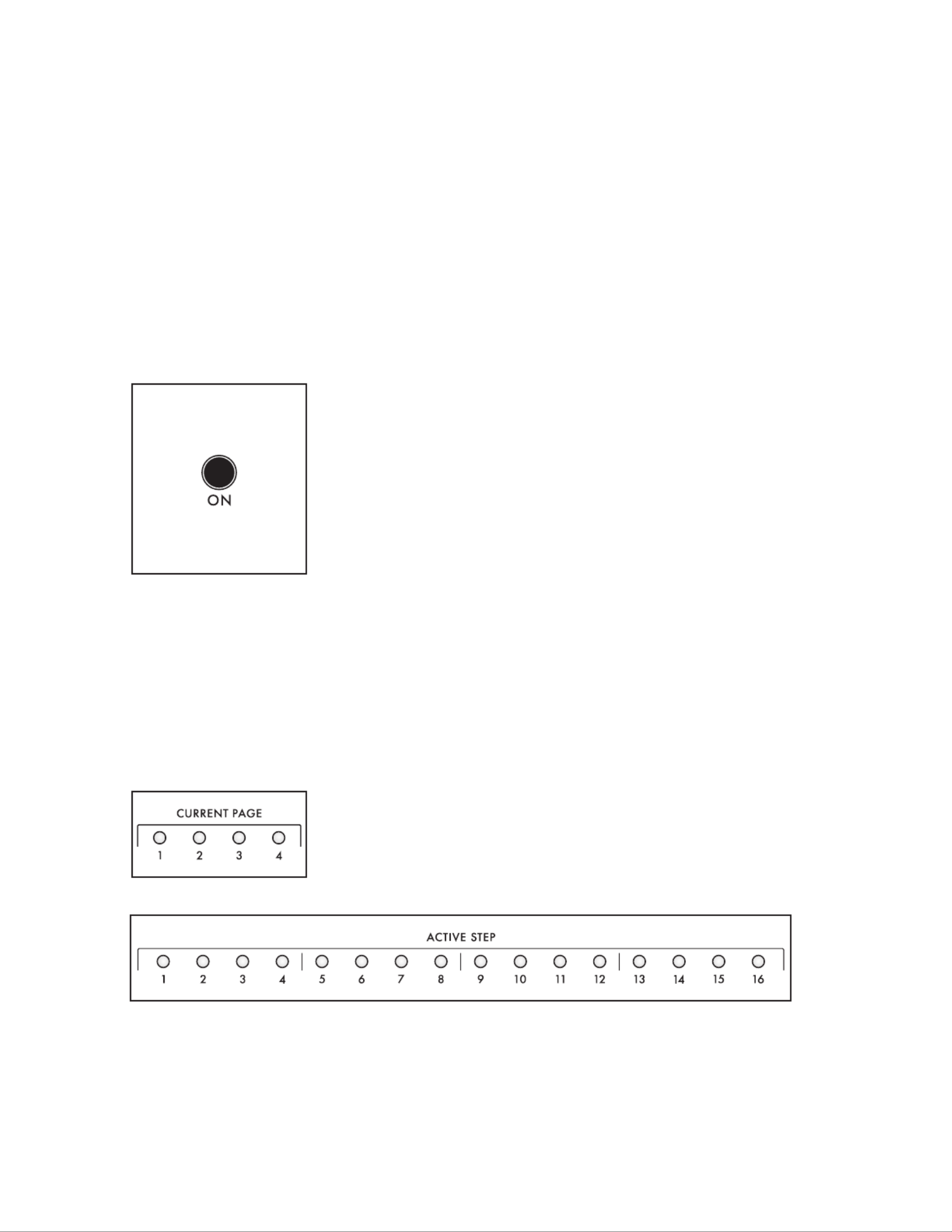
82
SEQUENCER
Although their function is pretty straight forward, sequencers are fairly remarkable. As the name
implies, they are responsible for memorizing, saving, and replaying a sequence of notes – either in a
continuous loop, or as a one-time event. The sequencer is one of the founding elements of electronic
music production; playing a series of pitches with clockwork precision, leaving the performer free to
continually modify the timbre and tweak countless parameters. In addition to the note value(s) stored
for each sequencer step, modulation routings and amounts can also be stored with each step.
In the Moog One, each Synth is equipped with a polyphonic step-sequencer. This allows each Preset
to access up to three sequencers simultaneously – one for each Synth. Each sequence can be up to 64
steps long, arranged as pages of 16 steps. Sequences can be easily recorded and edited, and they can
be transposed as they play back. The Sequencer can be sync’d to the Master Clock tempo – along with
the LFOs, EGs, and the Arpeggiator – to create a forceful rhythmic performance. Each sequence can
be saved as an individual entity, or as part of the active Synth/Preset.
ON (ON/LIT, OFF/UNLIT)
This ON button turns the Sequencer of the active Synth On and Off.
Turning the Sequencer On will not begin the playback of an existing
sequence or the recording of a new one. Instead, the ON button
controls whether the Sequencer outputs notes to the Synth or not.
RATE (0 10)to
The RATE knob sets the speed of the Sequencer. The actual tempo value ranges from 10 BPM to 280
BPM. The Sequencer Rate can run at an independent speed, or it can be synchronized to the Master
Clock using the parameters accessed in the Sequencer page. The MORE RATE knob LED will ash at
the current tempo setting.
NOTE: If the Sequencer is sync’d to the Master Clock, then rotating the knob will select quantized RATE
clock divisions of the Master Clock. All of the SYNC parameters are available in the Sequencer MORE page.
CURRENT PAGE / ACTIVE STEP (LED INDICATORS)
The current Sequencer Step is indicated by the four CURRENT PAGE
LEDs, and by the sixteen LEDs.ACTIVE STEP

83
SEQUENCER (Continued)
RETURN TO ZERO
Pressing the |tRTZ button resets the sequencer to the rst step.
START/STOP (RUNNING/LIT, STOPPED/UNLIT)
This u|| START/STOP button acts as a toggle, either setting the
Sequencer to run, beginning at the rst step, or stopping the Sequencer
at the current step.
TIP: To start multiple sequences simultaneously – that is, one sequence
from Synth 1 plus a second from Synth 3, for example – use the PANEL
FOCUS buttons in the Center Console to select more than one Synth,
and then press the u|| (START/STOP) button.
RECORD (RECORDING/LIT, NOT RECORDING/UNLIT)
Pressing the O RECORD button places the sequencer in the Record mode.
Press the O RECORD button a second time to exit the Record mode.
ADV (ADVANCE – STEP BACK, STEP FORWARD)
These buttons are used to select the current sequence step. The current
playback step is indicated by the CURRENT and PAGE ACTIVE STEP
LEDs. Press the button(s) until you reach the desired step.
TIP: These buttons can be used to select a step in the Step Edit screen even
when the sequence is running, although the Front Panel CURRENT PAGE
and ACTIVE STEP LEDS will instead show the current playback step.
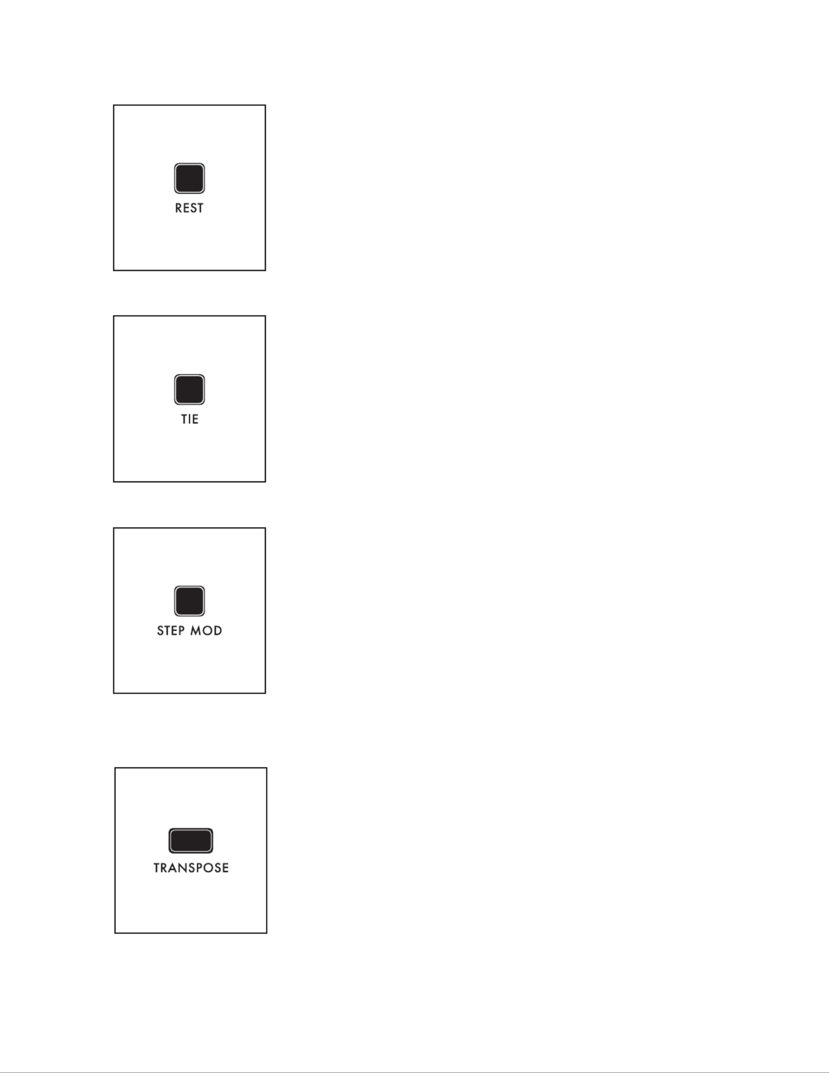
84
SEQUENCER (Continued)
REST (ON/LIT, OFF/UNLIT)
Pressing the button toggles a musical rest on or off for the current REST
sequence step. If there is a rest assigned to the current step, then any
notes entered on that step will not play.
NOTE: As the sequence plays, the REST button will light to indicate that
the current step has been designated as a rest.
TIE (ON/LIT, OFF/UNLIT)
Pressing the button adds a musical tie to the current step TIE
highlighted in the Step Edit screen, connecting the notes in this step
into the next, without re-triggering the envelopes at the beginning of
the next step.
NOTE: As the sequence plays, the TIE button will light to indicate that the
current step has been entered as tied to the next step.
STEP MOD (ON/LIT, OFF/UNLIT)
Nearly any Synth parameter can be given a different value for the
current step in the Step Edit page. But to quickly record value changes
as you sweep a parameter - storing a new value at each step as the
Sequencer is running - press the STEP MOD button to turn it On
(lit), and then tweak a knob, entering a new value (offset) for each
step. As long as the STEP MOD button is lit, you can continue to
enter modulation values for multiple parameters just by rotating the
corresponding knob. Finally, turn the Step Mod function Off by pressing
the STEP MOD button a second time. Once entered, this data can be
accessed and edited using the Step Edit feature.
NOTE: The Sequencer does not need to be placed in the Record mode to use the Step Mod feature.
TRANSPOSE (ON/LIT, OFF/UNLIT)
The playback of the sequence can be transposed to begin on a new key;
all notes in the sequence will be transposed by that same amount. For
example, if the sequence is of a C Major scale, transposing up a fourth
(ve keys) will produce an F Major scale. Press the TRANSPOSE button
to turn the Transpose feature On (the button is lit), and play a new
note on the keyboard to transpose the sequence; the sequence can be
continually transposed by playing new notes on the keyboard. Press the
TRANSPOSE button a second time to turn the Transpose feature Off
(the button goes dark).
NOTE: When the TRANSPOSE button is lit (Transpose feature On), notes played on the keyboard will
not sound the active synth. Instead, the keys are used only to enter a Transpose amount.

85
SEQUENCER (Continued)
NOTE TRIG (ON/LIT, OFF/UNLIT)
The Note Trigger function sets up an alternate play mode for controlling
the sequence playback. When the button is On, the NOTE TRIG
sequence will begin as soon as one (or more) keys are pressed; playback
will stop when all keys have been released. This can be an excellent
performance tool.
NOTE: The Note Trigger play method and the Start/Stop play method are
mutually exclusive; selecting one will disable the other.
STEP EDIT (ON/LIT, OFF/UNLIT)
Pressing the STEP EDIT button opens the Step Edit screen in the Center Console Display; the button
will remain lit. Press the HOME button on the Front Panel to exit the Step Edit mode.
ENTERING NOTE DATA (STEP EDIT MODE)
Notes entered into the Sequencer are displayed in a grid, where each column represents one step of
the sequence, and each row (lane) shows the note assigned to each step. Each lane can be thought of
as monophonic, so adding more lanes allows more notes to be assigned to each step. Each Sequence
can be up to 64 steps in length, which is shown on the Step Edit screen, and indicated on the Front
Panel as four pages of sixteen steps each. The exact number of steps is determined by the LENGTH
parameter in the Sequencer page. MORE
BEGINNING WITH AN EMPTY
SEQUENCE
The active Synth may or may not already
have data stored in the Sequencer. When
you press the STEP EDIT button on
the Front Panel and see the following
screen, this is a good indication that the
Sequencer is empty and awaiting new
data.
If there is already data present in the
Sequencer, you can clear the existing
data and start with a clean slate. Open
the Sequencer MORE page by pressing
the triangular button located in the upper right corner of the Sequencer module on the Front MORE
Panel. When the page opens, press the MORE CLEAR SEQUENCE Soft Button at the top of screen to
initialize the Sequencer and remove all data from the active Sequence.
NOTE: Pressing SHIFT + DELETE while the top (step number) row is selected on the STEP EDIT page
will also clear the entire current sequence.

86
SEQUENCER (Continued)
RECORDING NOTES & ADDING LANES
If it is not already selected, press the
NOTES Soft Button at the top of the
screen. Press the RECORD button on the
Front Panel (the button will light). Notice
how the Step Indicator has turned to red,
showing that the Record mode is On.
Notes may be entered using the keyboard.
Once a note is played, the sequence will
advance to the next step and wait for the
next note, and so on. As you enter notes,
You can use the ADV buttons to
move from step to step, or you can turn
the Master Encoder to scroll left/right through the steps. Two soft buttons at the top of the screen
allow you to move the selection Up or Down between rows (Lanes). You can also navigate up and
down by turning the Master Encoder while SHIFT is active.
Each lane can only support one note per
step, so adding more lanes is required to
have multiple notes on each step. Pressing
the ROW DOWN Soft button is one way
to add an additional lane. You can also
simply play multiple notes on a single step;
Moog One will create a new lane for each
additional note played. Only one lane can
be active/highlighted at once, so if you
create an additional lane and play only a
single note for that step, it will be entered
into the active lane.
NOTE: While it is possible to make your initial pass of entering sequence data with the Record Mode on
and the Sequencer running, it is not recommended. Without a reference audio click and only the visual
indicators, entering a sequenced phrase correctly will be tricky.

87
SEQUENCER (Continued)
TYPES OF NOTE DATA (NOTES, TIES, RESTS, RATCHETS)
Each sequence step can be entered as a Note, a Tie (creating a pair of Tied Notes), or a Rest. These
designations – and the Ratchet Count – can be reassigned while editing.
NOTES
Entering a Note creates a box that sits within the sequence grid for that
specic step. The Note name is displayed as well. The vertical height of
the box within the grid indicates the Velocity Level of the Note; the width
indicates the Gate Time of the Note.
TIES
Any Note can be designated as a Tie, as indicated by a small arrow
pointing to the following step. This instructs the sound engine (and the
corresponding MIDI output) to play the following step using the same
voice as in a legato fashion, without retriggering the EGs, etc.
RESTS
Entering a Rest places a silent step into the sequence. The Step Indicator
for this step will be shaded.
TIP: A Rest step can be empty, or it may contain Note value(s). This
allows the Note(s) to be restored by removing the Rest status of the step.
RATCHET STEPS
The Ratchet parameter allows the Sequencer to re-articulate a note
multiple times inside of a single step; a sort of sequence stutter mode.
The Ratchet Soft Knob is used to control the number of “ratchets” for
the selected note.
TIP: Often it is easier to create a step sequence by entering a Note for
every step, and then going back to designate individual steps as Rests
and Ties to capture the desired phrasing.

88
SEQUENCER (Continued)
EDITING NOTE DATA
The Velocity, Gate Time, Ratchet Count, and Note can be edited for every sequence step. In addition,
the Tie and Rest status of each note in every step can be reassigned. Note data can be edited in the
Step Edit screen, whether the Record function is On or Off.
NOTE (OFF, C0 to G10)
From the Step Edit screen, turn the Master Encoder to select individual notes in a step. Once
selected, the Note parameter will display at the bottom of the screen. Use the Note Soft Knob
to change the note assigned to a specic lane of particular step.
VELOCITY (1 127)to
Entering a Note creates a box that sits within the sequence grid for that specic step. The
vertical height of this box within the grid indicates the Velocity Level of the note. Use the
Velocity Soft Knob at the bottom of the screen to change the Velocity Level of the Note
assigned to a specic lane of particular step.
GATE (1% 100%)to
Entering a Note creates a box that sits with in the sequence grid for that specic step. The
horizontal width of this box within the grid the width indicates the Gate Time of the Note. Use
the GATE Soft Knob at the bottom of the screen to change Gate Time of the Note assigned to
a specic lane of particular step.
TIP: The last value set using the GATE Soft Knob will be applied to all subsequent new notes.
RATCHET (1 4)to
Ratcheting allows the Sequencer to re-articulate a note multiple times inside of a single step; a
sort of sequence stutter mode. This is an excellent tool for creating multiple triggers of the same
note without using up multiple steps. The Ratchet Soft Knob at the bottom of the screen is used
to control the number of “Ratchets” for the selected Note. A value of 1 equals no ratcheting.
EDITING MULTIPLE NOTES
Pressing the ROW UP button until it reaches the the current Step number will highlight and select all
of the Notes on the current step. The Velocity Level, Gate Time and Ratchet Count can be adjusted
simultaneously using the Soft Knobs at the bottom of the screen. Rotating the Master Encoder to the
right or left will restore the cursor to quickly select steps 1-64.
DELETING NOTES
Any highlighted note in any lane, on any step, can be deleted using the DELETE button on the Front
Panel. Using the Master Encoder to select an entire row of notes, and then pressing DELETE will
remove all of the notes in that step. If a specic row has been selected with the Row Up or Row Down
Soft buttons, pressing + SHIFT DELETE will remove the currently selected lane. Pressing the CLEAR
SEQUENCE MORE Soft Button on the Sequencer page will initialize the Sequencer and eliminate all
data from the active Sequence.
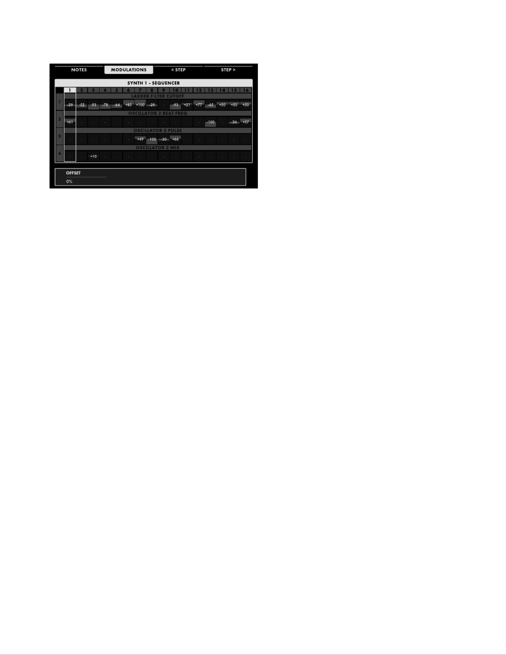
89
SEQUENCER (Continued)
ENTERING MODULATION DATA
(Step Edit Mode)
Each step of the sequence can also be
assigned a number of modulation routings.
Moog One handles these modulation
values by creating an offset value that
is combined with other values affecting
the same parameters. This allows the
performer to manually sweep a knob
value, without the Sequencer constantly
interrupting the sweep with absolute values
stored for each step. These offsets are
bipolar, meaning they can apply a positive
or a negative amount of change to the
parameter value, and they are proportional, being expressed as a percentage value.
As with entering and editing notes, the Modulation routings are applied using lanes. Each lane
is limited to one Modulation destination. While the CONTROLLER, AMOUNT, CATEGORY, and
DESTINATION Parameters set with the Soft Knobs found at the bottom of the screen are universal
for the selected lane, the values are set for each individual step.OFFSET
ENTERING MODULATION DATA IN REAL TIME
By far, the simplest way to add modulation data to the sequence is by using the Step Mod function
to record the changing value of a particular parameter as the Sequencer is running – either while
recording or playing back. With the sequence stopped, the Step Mod method can be used to quickly
edit modulation values in the STEP EDIT page. If it is not already open, press the STEP EDIT button
to open the MODULATION SEQUENCE page. Press the MODULATIONS Soft Button at the top of the
screen to open the MODULATION SEQUENCE screen.
NOTE: Using the function does not require opening the page or pressing the STEP MOD STEP EDIT
MODULATIONS Soft Button; but doing so will allow you to see – and edit – the data entered in this manner.
Now press the STEP MOD button (the button will light) in the Sequencer module on the Front Panel
and tweak any modulate-able parameter on the Front Panel. This will instantly set up a new Modulation
lane using that parameter as the destination. While you can manually advance from step to step and
change each value individually, you can also set the Sequencer to run, and twist and tweak away on
that same parameter knob. The changing values will be recorded automatically for each step. Tweaking
additional knobs will instantly set up a new Modulation lane for each destination, with the values again
being recorded automatically for each step. Press the lit button (the button will go dark) to STEP MOD
exit the STEP MOD mode.

90
SEQUENCER (Continued)
ENTERING MODULATION DATA IN STEP TIME
While not as convenient as the Step Mod method, the manual entry mode allows you to address
each step individually, and to assign modulation destinations that do not have a corresponding Front
Panel knob – SVF Filter Spacing, for example. Here you will have to set up a Modulation lane, select
a Sequencer step, and dial in an offset value. If it is not already selected, press the MODULATIONS
Soft Button at the top of the screen. Press the ROW DOWN Soft button and then press down on the
MASTER ENCODER to create the rst Modulation lane for your sequence. Using the Soft Knobs at the
bottom of the screen, set a modulation destination by adjusting the CATEGORY and DESTINATION
values. The Destination options are dependent on the selected Category.
In addition, a CONTROLLER can also be assigned to the Modulation parameter occupying a specic
lane. If no Controller is chosen, the Offset values will be applied at full strength to the destination
parameter. However, assigning a Controller – and a percentage value – allows the strength of AMOUNT
the sequenced modulation to be articulated as part of a performance. At an Amount value of 0%, the
assigned Controller will have no effect. Using an Amount value of 100%, the assigned Controller can
fully attenuate the sequenced modulation value, when the Controller is at its minimum position (value).
See the appendix at the end of this chapter for the possible values. Once these values have been set,
press down on the Master Encoder for any desired step and use the OFFSET Soft knob to set the
OFFSET amount for each sequence step. Press the ROW DOWN Soft button and then press down on
the MASTER ENCODER to create a new Modulation lane. Repeat the same procedure for assigning a
modulation destination to your Modulation routing lane, and for setting the offset values for each step.
EDITING MODULATION DATA
The CONTROLLER, AMOUNT, CATEGORY, and DESTINATION of each modulation lane can be freely
edited, as can the individual values, You can use the OFFSET values. As you enter OFFSET ADV
buttons to move from step to step, or you can turn the Master Encoder to scroll left/right through the
steps. Two soft buttons at the top of the screen allow you to move the selection Up or Down between
rows (lanes). You can also navigate up and down by turning the Master Encoder while SHIFT is active.
EDITING MULTIPLE OFFSET VALUES
For any sequence step that has Modulation data in more than one lane, pressing the ROW UP Soft
button until the current Step is selected will highlight and select all of the lanes in that step. The
OFFSET values can be adjusted simultaneously using the Soft Knob at the bottom of the screen.
Pressing the ROW DOWN Soft button will cause the cursor to select only one lane at a time. Continue
to rotate the Master Encoder to the right to move between steps.
DELETING MODULATION DATA
Any highlighted value in any lane, on any step can be deleted using the OFFSET DELETE button on the
Front Panel. Selecting multiple values and then pressing OFFSET DELETE will remove all of the OFFSET
values at that step. Pressing + SHIFT DELETE will remove the currently selected lane. Pressing the
CLEAR SEQUENCE Soft Button on the Sequencer MORE page will initialize the Sequencer and eliminate
all data - Notes and Modulation - from the active Sequence.

91
NONE
MOD WHEEL
PITCH WHEEL
PAD X
PAD Y
PAD PRESSURE
PAD GATE
VELOCITY
AFTERTOUCH
KEY PITCH
KB GATE
SUSTAIN
EXP 1
EXP 2
CV IN 1
CV IN 2
FILTER EG
AMPLIFIER EG
MODULATION EG
LFO 1
LFO 2
LFO 3
LFO 4
RANDOM
CONSTANT
ALL OSCS SVF FILTER
PITCH 1 LFO CUTOFF
PITCH EG MOD RESONANCE
TRIANGLE LFO 3 MOD SPACING
PULSE LFO 3 MOD EG AMOUNT
FM AMOUNT LFO 2 AMOUNT
OSC 1, 2, 3 FM AMOUNT
OCTAVE LADDER FILTER
FREQUENCY CUTOFF
BEAT RESONANCE
SAW EG AMOUNT
TRIANGLE LFO 2 AMOUNT
PULSE FM AMOUNT
MIX EG 1, 2, 3
NOISE DELAY
COLOR MIX ATTACK
ATTACK HOLD
SUSTAIN DECAY
RELEASE SUSTAIN
VCA RELEASE
LEVEL MULTI TRIGGER
PAN SYNC
FILTERS LOOP
SVF/LADDER MIX LATCH
LFO 1, 2, 3, 4
RATE
WAVEFORM
VARIATION
DELAY
RAMP UP TIME
RAMP DOWN TIME
CONTROLLERS CATEGORY/DESTINATION
SEQUENCER (Continued)
STEP EDIT MODULATION APPENDIX

93
SEQUENCER (Continued)
LENGTH (1 64)to
By changing the Length, the sequence can be set to contain any number of steps, from 1 to 64.
Combined with the CLOCK TIMING parameter, it is possible to generate sequences of differing
lengths, feels, and time signatures.
FOLLOW SWING (OFF, ON)
The Master Clock includes parameters related to adding swing to the beat. When Sync’d to the Master Clock,
the Sequencer can either follow this swing information, or ignore it and play strictly to the BPM setting.
NOTE RESET (OFF, ON)
This parameter species how the timing of the Sequencer will behave when a new note is played on
the keyboard, if the button in the Sequencer module is also On (lit). When this NOTE NOTE TRIG
RESET parameter is On, the Sequencer begins instantly, resetting the downbeat timing of the current
Clock Division to match the note as it is played. When Note Reset is Off, the Sequencer will wait for the
start of the next specied Clock Division before the pattern begins.
RESTART ON HOLD (OFF, ON)
This parameter species how the timing of the Sequencer will behave when the HOLD button on the
Front Panel is On (lit) and the button in the Sequencer module is also On (lit). When this NOTE TRIG
RESTART ON HOLD parameter is On, playing any new note – with no other no other notes held down –
will reset the sequence to begin playing from the rst step. When this ON HOLD parameter RESTART
is Off, playing any new note will not restart the sequence.
NOTE NOTE: If the parameter is off, and the RESTART ON HOLD HOLD, TRIG, and TRANSPOSE
buttons from the Sequencer module area all set to On, then playing a new note while a previous note
is still held will transpose the sequence without resetting back to step one.
RESTART ON TRIG (OFF, ON)
This RESTART ON TRIG (Restart On Note Trigger) parameter species how the timing of the
Sequencer will behave when the button in the Sequencer module on the Front Panel is NOTE TRIG
On (lit). When this Restart On Note Trigger parameter is set to On, then using the Note Trigger feature
to initiate the sequence playback will always reset the sequence to restart at step one. When this
Restart On Note Trigger parameter is set to Off, using the Note Trigger feature to initiate the sequence
playback will resume the playback of the sequence from the active step.
TRANSPOSE MODE (START KEY, INTERVAL)
When the TRANSPOSE button in the Sequencer module on the Front Panel is set to On (lit), the playback
of the sequence can be transposed. There are two methods for determining the transpose amount.
START KEY
Using the Start Key method, any key can be chosen to serve as the starting note of the
sequence, and the remaining notes will also be transposed by the same amount to preserve
their correct intervals in relation to the new Start Key.
INTERVAL
The Interval method uses Middle C on the keyboard as a reference point, and allows the
sequence to be transposed by a specic interval, regardless of the original key. In this way,
playing F above Middle C would transpose the sequence up a fourth. Even if the original key
and starting note was not C, the transposition would still be equal to a fourth, so E would
become A, etc.

94
SEQUENCER (Continued)
ONE SHOT (OFF, ON)
Once the sequence begins to play, it can play to the end and stop (One Shot On), or it can play to the
end and then loop around and restart from the beginning (One Shot Off). This looping behavior is the
way most sequencers operate, but the addition of the One Shot option allows an intricate sequence
pattern to be launched at will, anywhere in the song, and play through only once – although the One
Shot playback can be launched numerous times. This is a great way to add a live ourish of notes when
transitioning from verse to chorus, playing a signature lick perfectly every time, etc.
RECORDING MODE (REPLACE, OVERDUB, FOCUSED)
Once a sequence has been recorded, there are three ways that the sequencer can respond to new
notes being recorded over existing notes.
REPLACE (DEFAULT)
Newly recorded notes will replace any previously notes recorded on the same step.
OVERDUB
Newly recorded notes are added to the notes that were already there, without replacing the
existing information.
FOCUSED
Here, an individual step may be chosen for editing and the new data entered as the sequence
is running. Use the or ADV buttons to select the step to be edited. The stationary
selected step indicator will be dimly lit; the moving current step indicator will be fully lit. Play
the new note(s) to replace the note(s) currently held in the selected step at any time. When
the sequence advances to the selected step, the new notes will be heard. This process can be
repeated over and over again, so long as the sequence is running. When the sequence is not
running, this mode is identical to the REPLACE mode.
OUTPUT (SYNTH 1/2/3, ALL SYNTHS)
This setting controls which Synth(s) will play in response to this sequence. The options are either the
currently selected Synth (Synth 1, 2, or 3), or ALL SYNTHS. The ALL SYNTHS option can be used to
create a single sequence that will play all the parts of a split or layered sound.
CLEARING THE SEQUENCER
Pressing the CLEAR SEQUENCE Soft Button at the top of the screen will remove all data from the
active sequence.
TIP: When editing sequence data, you can press the SNAPSHOT button located in the Center Console to
perform a micro-save of your current edits before clearing the sequence, should you change your mind
and wish to reload any previously unsaved sequence data.
DUPLICATING SEQUENCE DATA
Using the DUPLICATE X-Y Soft Button at the top of the Sequencer MORE page, sequence data can be
copied and appended to the existing sequence by adding steps (up to the 64 step maximum). The X value
indicates the rst step of the data to be copied; the Y value indicates the last step of the data to be copied.
With the sequence paused, use the or ADV buttons to select the rst step of the data to be copied.
Next, hold down the button and use the or buttons to select the last step of the data to be SHIFT ADV
copied. Press the DUPLICATE Soft Button to add a copy of the selected data to the end of the sequence.
EXAMPLE: Set the value of the rst step to be copied to 1; then set the value of the last step to be
copied to 8. Now, when the DUPLICATE 1-8 Soft Button is pressed, the selected data present in steps 1-8
will be duplicated to steps 9-16.

95
SEQUENCER (Continued)
LOADING A SEQUENCE
Pressing the LOAD Soft Button at the top
of the screen will open the Load Sequence
screen.
The left pane will show a list of all of the
available Sequences. To make it easier
to locate a saved Sequence, this list can
be sorted by name by pressing the SORT
BY NAME Soft Button at the top of the
screen. The Sequence list can also be
sorted by the date the sequence was most
recently saved, using the SORT BY DATE
Soft Button. The upper right pane will
display any performance notes that were added to and saved along with Sequence. The lower right
pane will display a date stamp of when the selected Sequence was most recently saved to memory.
Rotate the Master Encoder to highlight and select a specic Sequence, then press down on the Master
Encoder or press the LOAD Soft Button at the top of the screen. A small indicator will appear next to
the Sequence name, showing that it is the active Sequence. Once the Sequence is loaded, you can play
it, change the Sequence settings found in the Sequencer page, or press the MORE STEP EDIT button
to open the Step Edit window to edit the content of the sequence.
TIP: When the PRESET AUTOLOAD function [SETTINGS / GLOBAL / HARDWARE SETTINGS] is set to
ON, rotating the Master Encoder will automatically load the selected Sequence as you scroll through the
list, without the need to use the LOAD Soft Button.
SAVING A SEQUENCE
Once you have nished creating and/or
editing your Sequence, press the SAVE
Soft Button at the top of the screen. Here
you can name your edited Sequence.
When the screen opens, the SAVE NAME
Soft Button will already be selected, and
the screen prompt will ask you to name
the current sequence.
ENTERING TEXT
Moog One allows you to enter names and text directly from the keyboard. The white keys (naturals)
enter the characters; certain black keys (accidentals) have specic functions. See page 60 for more
information on entering text.
Once you have entered a name for the sequence, you can also enter any optional performance notes
using the same method. These notes can be quick reminders or application cues, such as “Starts on
F#” or “Use as the intro for Song 5” or “Launch sequence on last note of the bass solo,” etc. Press the
NOTES Soft Button and follow the screen prompts, using the same text entry method.
After naming the sequence and adding any performance notes, press the OK Soft Button to save the
sequence, or press the screen without saving.CANCEL Soft Button to exit the Sequence SAVE

96
EFFECTS
Moog One offers an extensive array of digital effects. Up to three individual Synth Effects (one per
Synth), and up to two Master Effects can all be operating at once. The Master Effects include a number
of premium studio-grade effects created by and licensed from renowned audio processing pioneer,
Eventide®. With the exception of these Eventide Master Effects, the Master Effect List is identical to the
Synth Effect list, and Synth Effects can be recalled and used as Master Effects as well – and vice-versa.
These digital effects are the only part of the Moog One audio path that is not in the analog domain. All
assigned Synth Effects and Master Effects are saved as part of the Preset. To create a pure all-analog
audio path, simply turn off the SYNTH EFFECT module ON and MASTER EFFECTS module ON buttons.
UNDERSTANDING SYNTH EFFECTS
ON (ON/LIT, OFF/UNLIT)
The ON button toggles the SYNTH EFFECT module On and Off; when
the button is lit, the Synth Effect is On.
CTRL 1 AND CTRL 2 KNOB
Synth Effects are applied individually; each
Synth has access to its own individual Synth
Effect. Once a Synth Effect is applied, any two
effect parameters can be controlled in real
time from the Front Panel using the CTRL 1
knob and CTRL 2 knob. Both of these knobs
will be pre-assigned to the two most-likely-
to-be-tweaked parameters in each Effect, but
they can be easily re-assigned to any available
parameter by using the EFFECT TYPE page.
The status of the button and the value of ON
the and knobs are saved as part CTRL 1 CTRL 2
of the Timbre.
SYNTH EFFECT STRUCTURE
Synth Effects are classied by type – Delay, Chorus, Flanger, etc. Once a particular type of effect has
been selected and loaded, the individual parameters may be adjusted, and your settings can be saved
as a Synth Effect Preset of that effect type. For example, if you select and load a Flanger-type Synth
Effect and tweak all of the parameters to your liking, you can save it as a Synth Effect Flanger, and give
it a name (such as ) so you can recall it and reuse it again and again.MY SWEET FLANGER
The structure of the Synth Effect uses a monaural input and a stereo output; this stereo output is mixed
with the stereo buss and/or the MAIN L/R SUB L/R buss. The rst parameter of every Synth Effect is the
MIX parameter, which sets a balance between the Wet (affected) and Dry (unaffected) signal.
TECHNICAL NOTE: Although PAN can be assigned as a modulation destination using the Modulation
Matrix (allowing the panning of individual voices as they are played), this per-voice panning cannot be
preserved in the monaural buss feeding the Synth Effect. The per-voice panning will continue to affect
the Dry (unprocessed) signal, but the Wet (processed) signal will rely on the Synth pan position, as
determined by the VCA MORE page settings.

98
EFFECTS (Continued)
CHANGING THE VALUE
Rotate the Soft Knob below the parameter
name to change its value. In some cases,
the Soft Knob simply turns a function On
or Off. In other cases, the Soft Knob may
choose from a list of values or settings,
and in other cases, the Soft Knob is
dialing in a value – either absolute or a
percentage.
SELECTING A ROW
The scroll bar at the right edge indicates
the current row. Rotate the Master
Encoder to the right to highlight the next
row of parameters. Rotating the Master Encoder to the left will select a previous row. Again, rotate the
Soft Knob below the parameter to change its value.
NOTE: Each Synth Effect Type has its own distinct set of editable parameters. A list of the onboard
effects – including all editable parameters and the parameters pre-assigned to the CTRL 1 and CTRL 2
knobs – is found in the (page 103-111).EFFECTS APPENDIX
NOTE: The last parameter listed for each Synth Effect is . When the SYNC SYNC parameter is set to On,
the time-based parameter values will switch from absolute values to clock-division values of the Master
Clock tempo.
SAVING AN EDITED EFFECT
Once you have made all of your edits to
the Effect, press the Soft Button at SAVE
the top of the screen. Here you can name
your edited Effect.
ENTERING TEXT
Moog One allows you to enter names
and text directly from the keyboard. The
white keys (naturals) enter the characters;
certain black keys (accidentals) have
specic functions.
• Keys C#1 - D#2 select the character set.
• Key F#4 removes the current name and randomly generates a new name.
• Key G#4 clears all the characters in the screen.
• Key A#4 deletes the character to the left of the cursor.
• Keys C#5 and D#5, respectively, change the character immediately preceding the cursor to the
previous or next symbol in the current character set, changing an M to an L or an N, for example with a
single key press.
• Keys F#5 and G#5 move the cursor left or right, respectively.
• Key A#5 adds a space.
NOTE: The note numbers given above relate to the onscreen keyboard, and do not reect the keys’
actual MIDI Note numbers, etc.
TIP: You can also enter names directly, using a standard USB keyboard connected to the Moog One’s
USB HOST port.
Press the OK Soft Button to save your Effect Preset under this new name. Press the CANCEL Soft
Button to exit without saving.

99
MASTER EFFECTS
UNDERSTANDING MASTER EFFECTS
ON (ON/LIT, OFF/UNLIT)
The button toggles the ON SYNTH EFFECT module On and Off; when
the button is lit, the Synth Effect is On.
SEND 1 AND SEND 2 KNOBS
Unlike the Synth Effects, which are applied per
Synth, Master Effects are available to any and
all Synths within the active Preset. The SEND
1 and SEND 2 knobs located on the Front
Panel determine how much signal from each
individual Synth is being fed into the Master
Effect Buss. The status of the ON button and
the value of the and knobs are SEND 1 SEND 2
saved as part of the Timbre.
The Master Effects buss offers two inputs and two outputs, allowing the Master Effects to be
congured to operate as one stereo in/stereo out processor (STEREO), or as two mono in/stereo out
processors (DUAL MONO). When the parameter in the Master Effects MASTER BUSS MODE MORE
page is set to , the indicator will light. STEREO STEREO LED
TECHNICAL NOTE: Although PAN can be assigned as a modulation destination using the Modulation
Matrix (allowing the panning of individual voices as they are played), this per-voice panning cannot be
preserved in the dual mono buss feeding the Master Effects. The per-voice panning will continue to
affect the Dry (unprocessed) signal, but the Wet (processed) signal will rely on the Synth pan position,
as determined by the VCA page settings. However, in the Stereo mode, the inputs to the Master MORE
Effects are stereo, and the per-voice panning data is preserved.
Included in the Master Effects are select studio-grade effects created by Eventide®, and licensed
for Moog One use. Due to their innate complexity, only one of these premiere Eventide effects may
be used at a time, even when the Master Effects are congured in the Dual Mono mode. A second
Master Effect may indeed still operate alongside the Eventide effect; the limitation is only that no two
Eventide effects can operate simultaneously.
NOTE: If one of the Eventide effects is already assigned to one of the Master Effects, say Master Effect 1,
then the Eventide effects will appear grayed-out in the EFFECT 2 TYPE list, and they will be unselectable.
Termékspecifikációk
| Márka: | Moog |
| Kategória: | billentyűzet |
| Modell: | One |
Szüksége van segítségre?
Ha segítségre van szüksége Moog One, tegyen fel kérdést alább, és más felhasználók válaszolnak Önnek
Útmutatók billentyűzet Moog

20 Július 2024
Útmutatók billentyűzet
- billentyűzet Sony
- billentyűzet Yamaha
- billentyűzet Fujitsu
- billentyűzet Acer
- billentyűzet Sharkoon
- billentyűzet Nedis
- billentyűzet DeepCool
- billentyűzet Philips
- billentyűzet SilverCrest
- billentyűzet RCF
- billentyűzet JVC
- billentyűzet Lenovo
- billentyűzet Evolveo
- billentyűzet HyperX
- billentyűzet Casio
- billentyűzet Sven
- billentyűzet Gamdias
- billentyűzet HP
- billentyűzet Apple
- billentyűzet Fellowes
- billentyűzet Medion
- billentyűzet Vimar
- billentyűzet LogiLink
- billentyűzet Technics
- billentyűzet Roland
- billentyűzet Digitus
- billentyűzet Zebra
- billentyűzet Xiaomi
- billentyűzet GoGen
- billentyűzet Dell
- billentyűzet Boss
- billentyűzet Crestron
- billentyűzet Gigabyte
- billentyűzet Tripp Lite
- billentyűzet Conceptronic
- billentyűzet Hikvision
- billentyűzet Vivanco
- billentyűzet V7
- billentyűzet Microsoft
- billentyűzet Asus
- billentyűzet Arturia
- billentyűzet Keychron
- billentyűzet Hama
- billentyűzet Zoom
- billentyűzet Renkforce
- billentyűzet Korg
- billentyűzet Blue Element
- billentyűzet GPX
- billentyűzet Hori
- billentyűzet Genesis
- billentyűzet M-Audio
- billentyűzet AOC
- billentyűzet Iogear
- billentyűzet 4ms
- billentyűzet Logitech
- billentyűzet Dahua Technology
- billentyűzet Scosche
- billentyűzet Denver
- billentyűzet Trevi
- billentyűzet Ewent
- billentyűzet The T.amp
- billentyűzet BT
- billentyűzet Black Box
- billentyűzet Aluratek
- billentyűzet NGS
- billentyűzet Joy-It
- billentyűzet MSI
- billentyűzet Livoo
- billentyűzet Gembird
- billentyűzet Energy Sistem
- billentyűzet Native Instruments
- billentyűzet Niceboy
- billentyűzet SPC
- billentyűzet Speed-Link
- billentyűzet Kingston
- billentyűzet Behringer
- billentyűzet ModeCom
- billentyűzet ADATA
- billentyűzet Cooler Master
- billentyűzet PreSonus
- billentyűzet Deltaco
- billentyűzet Steelseries
- billentyűzet Manhattan
- billentyűzet Kogan
- billentyűzet Sigma
- billentyűzet Alesis
- billentyűzet Media-Tech
- billentyűzet IK Multimedia
- billentyűzet ION
- billentyűzet Blaupunkt
- billentyűzet NZXT
- billentyűzet Viper
- billentyűzet Thomann
- billentyűzet Hammond
- billentyűzet Perixx
- billentyűzet Razer
- billentyűzet Samson
- billentyűzet Logik
- billentyűzet Millenium
- billentyűzet Xtrfy
- billentyűzet Abus
- billentyűzet SureFire
- billentyűzet Trust
- billentyűzet AKAI
- billentyűzet Konig
- billentyűzet Marmitek
- billentyűzet TechniSat
- billentyűzet Polyend
- billentyűzet Pyle
- billentyűzet Roccat
- billentyűzet Watson
- billentyűzet Corsair
- billentyűzet Lindy
- billentyűzet NACON
- billentyűzet Fender
- billentyűzet Vorago
- billentyűzet Arctic Cooling
- billentyűzet Ergoline
- billentyűzet Kurzweil
- billentyűzet CM Storm
- billentyűzet Siig
- billentyűzet Novation
- billentyűzet Homematic IP
- billentyűzet Ketron
- billentyűzet Thermaltake
- billentyűzet Medeli
- billentyűzet Tiptop Audio
- billentyűzet ENDORFY
- billentyűzet Genius
- billentyűzet Gamber-Johnson
- billentyűzet Adj
- billentyűzet Anker
- billentyűzet Gravity
- billentyűzet Havis
- billentyűzet ILive
- billentyűzet Rapoo
- billentyűzet Nektar
- billentyűzet Soundsation
- billentyűzet Cougar
- billentyűzet IQUNIX
- billentyűzet Ducky
- billentyűzet Savio
- billentyűzet Enermax
- billentyűzet InLine
- billentyűzet Quazar
- billentyűzet CSL
- billentyűzet Cherry
- billentyűzet Belkin
- billentyűzet Xcellon
- billentyűzet K&M
- billentyűzet Elgato
- billentyűzet Erica Synths
- billentyűzet Intellijel
- billentyűzet Alienware
- billentyűzet A4tech
- billentyűzet BeeWi
- billentyűzet Eminent
- billentyűzet Trekstor
- billentyűzet Targus
- billentyűzet Exibel
- billentyűzet Aukey
- billentyűzet Kensington
- billentyűzet Brigmton
- billentyűzet Techly
- billentyűzet BlueBuilt
- billentyűzet Ednet
- billentyűzet Connect IT
- billentyűzet Steren
- billentyűzet Sandberg
- billentyűzet Buffalo
- billentyűzet GeoVision
- billentyűzet Terris
- billentyűzet Evga
- billentyűzet Clas Ohlson
- billentyűzet Mede8er
- billentyűzet Sweex
- billentyűzet Vakoss
- billentyűzet KeySonic
- billentyűzet Natec
- billentyűzet Essentiel B
- billentyűzet RGV
- billentyűzet Tracer
- billentyűzet Zagg
- billentyűzet Veho
- billentyűzet Maxxter
- billentyűzet MT Logic
- billentyűzet Saitek
- billentyűzet Msonic
- billentyűzet Mitel
- billentyűzet BakkerElkhuizen
- billentyűzet XPG
- billentyűzet CME
- billentyűzet Adesso
- billentyűzet Satel
- billentyűzet Brookstone
- billentyűzet Man & Machine
- billentyűzet Brydge
- billentyűzet Satechi
- billentyűzet Mad Catz
- billentyűzet Cyborg
- billentyűzet Hawking Technologies
- billentyűzet Krom
- billentyűzet Iluv
- billentyűzet Avanca
- billentyűzet Mousetrapper
- billentyűzet Mediacom
- billentyűzet AZIO
- billentyűzet X9 Performance
- billentyűzet Ozone
- billentyűzet Woxter
- billentyűzet Ibm
- billentyűzet General Music
- billentyűzet Matias
- billentyűzet Keith MCmillen
- billentyűzet Trkstor
- billentyűzet Verbatim
- billentyűzet Zalman
- billentyűzet Contour Design
- billentyűzet Micro Innovations
- billentyűzet Hohner
- billentyűzet Goldtouch
- billentyűzet Merkloos
- billentyűzet Kawai
- billentyűzet Native
- billentyűzet I-onik
- billentyűzet Laney
- billentyűzet MaxMusic
- billentyűzet Inovalley
- billentyűzet Bontempi
- billentyűzet Logic3
- billentyűzet Penclic
- billentyűzet Bakker Elkhuizen
- billentyűzet Venom
- billentyűzet IPort
- billentyűzet R-Go Tools
- billentyűzet Schubert
- billentyűzet Nord Electro
- billentyűzet Icon
- billentyűzet X-keys
- billentyűzet Stagg
- billentyűzet PIXMY
- billentyűzet Promate
- billentyűzet ISY
- billentyűzet ThunderX3
- billentyűzet Hanwha
- billentyűzet FURY
- billentyűzet Pelco
- billentyűzet Studiologic
- billentyűzet Perfect Choice
- billentyűzet ASM
- billentyűzet NPLAY
- billentyűzet NUX
- billentyűzet Canyon
- billentyűzet STANDIVARIUS
- billentyűzet Dexibell
- billentyűzet Goodis
- billentyűzet Eclipse
- billentyűzet UGo
- billentyűzet Krux
- billentyűzet ActiveJet
- billentyűzet Alogic
- billentyűzet Genovation
- billentyűzet Rii
- billentyűzet Sequenz
- billentyűzet Redragon
- billentyűzet Hamlet
- billentyűzet Approx
- billentyűzet Gamesir
- billentyűzet SilentiumPC
- billentyűzet Leotec
- billentyűzet Nuki
- billentyűzet Nord
- billentyűzet The Box
- billentyűzet Mars Gaming
- billentyűzet Roline
- billentyűzet Acme Made
- billentyűzet Startone
- billentyűzet Vultech
- billentyűzet TEKLIO
- billentyűzet Mad Dog
- billentyűzet Raspberry Pi
- billentyűzet Kinesis
- billentyűzet Urban Factory
- billentyűzet Roadworx
- billentyűzet KeepOut
- billentyűzet CTA Digital
- billentyűzet Accuratus
- billentyűzet Seal Shield
- billentyűzet Kanex
- billentyűzet GETT
- billentyűzet Unitech
- billentyűzet Akko
- billentyűzet Mountain
- billentyűzet Groove Synthesis
- billentyűzet CoolerMaster
- billentyűzet 3Dconnexion
- billentyűzet IOPLEE
- billentyűzet Royal Kludge
- billentyűzet Universal Remote Control
- billentyűzet Logickeyboard
- billentyűzet Montech
- billentyűzet ID-Tech
- billentyűzet Patriot
- billentyűzet Voxicon
- billentyűzet On-Stage
- billentyűzet Carlsbro
- billentyűzet UNYKAch
- billentyűzet Xtech
- billentyűzet SMK-Link
- billentyűzet Loupedeck
- billentyűzet MK
- billentyűzet Nanoxia
Legújabb útmutatók billentyűzet
5 Április 2025
5 Április 2025
5 Április 2025
5 Április 2025
5 Április 2025
4 Április 2025
30 Március 2025
30 Március 2025
30 Március 2025
30 Március 2025