Használati útmutató Mitsubishi WD-73837
Mitsubishi
televízió
WD-73837
Olvassa el alább 📖 a magyar nyelvű használati útmutatót Mitsubishi WD-73837 (85 oldal) a televízió kategóriában. Ezt az útmutatót 10 ember találta hasznosnak és 2 felhasználó értékelte átlagosan 4.5 csillagra
Oldal 1/85

HOME THEATER TELEVISION
MODELS
C9 Series
737 Series
837 Series
OWNER’S GUIDE
Guidelines for setting up and using your new widescreen TV start on • page 7.
For questions:•
Visit our website at www.mitsubishi-tv.com. -
E-mail us at MDEAservice@mdea.com. -
Call Consumer Relations at - 800-332-2119.
For information on • System Reset, please see the back cover.
To order replacement or additional remote controls or lamp cartridges, visit our website at •
www.mitsuparts.com or call 800-553-7278.
837 Series.• IR emitter cables for NetCommand home-theater control are available for
purchase from Mitsubishi.
Call 800-553-7278 and
request either part number 242D483020
(two-ended cable) or part number 299P254020 (four-ended cable).
FCC Declaration of Conformity
Product: Projection Television Receiver
Models: WD-60C9, WD-65C9, WD-73C9
WD-60737, WD-65737, WD-73737,
WD-82737
WD-65837, WD-73837, WD-82837
Responsible
Party:
Mitsubishi Digital Electronics
America, Inc.
9351 Jeronimo Road
Irvine, CA 92618-1904
Telephone: (800) 332-2119
This device complies with Part 15 of the FCC Rules.
Operation is subject to the following two conditions:
(1)
This device may not cause harmful interference,
and
(2) This device must accept any interference
received, including interference that may cause
undesired operation.
Note: This equipment has been tested and found
to comply with the limits for a Class B digital device,
pursuant to part 15 of the FCC Rules. These limits
are designed to provide reasonable protection
against harmful interference in a residential instal-
lation. This equipment generates, uses and can
radiate radio frequency energy and, if not installed
and used in accordance with the instructions, may
cause harmful interference to radio communica-
tions. However, there is no guarantee that interfer-
ence will not occur in a particular installation. If this
equipment does cause harmful interference to radio
or television reception, which can be determined
by turning the equipment off and on, the user is
encouraged to try to correct the interference by one
or more of the following measures:
Reorient or relocate the receiving antenna. -
Increase the separation between the equip- -
ment and the receiver.
Connect the equipment into an outlet on -
a circuit different from that to which the
receiver is connected.
Consult the dealer or an experienced radio/ -
TV technician for help.
Changes or modifications not expressly
approved by Mitsubishi could cause harmful
interference and would void the user’s authority
to operate this equipment.
CAUTION
RISK OF ELECTRIC SHOCK
DO NOT OPEN
CAUTION: TO REDUCE THE RISK OF ELECTRIC
SHOCK, DO NOT REMOVE COVER (OR BACK).
NO USER SERVICEABLE PARTS INSIDE. REFER
SERVICING TO QUALIFIED SERVICE PERSONNEL.
TV WEIGHT: This TV is heavy. Exercise extreme care
when lifting or moving it. Lift or move the TV with a
minimum of two adults. To prevent damage to the TV,
avoid jarring or moving it while it is turned on. Always
power off your TV, unplug the power cord, and discon-
nect all cables before moving it.
WARNING: To reduce the risk of fire or electric shock,
do not expose this apparatus to rain or moisture.
WARNING: This product shall be connected to a
MAINS socket outlet with a protective earthing connec-
tion.
MAINS DISCONNECTION: The mains plug is used
as the disconnect device. The disconnect device shall
remain readily operable.
WARNING: This product contains chemicals known
to the State of California to cause cancer and/or birth
defects or other reproductive harm.
Note: Features and specifications described in this
owner’s guide are subject to change without notice.
Stand Requirement
CAUTION: Use these Mitsubishi TV models only with
the Mitsubishi stand models shown here. Other stands
can result in instability and possibly cause injury.
TV Model Stand Model
WD-60C9, WD-65C9
WD-60737, WD-65737
WD-65837
MB-S60/65A
WD-73C9
WD-73737
WD-73837
MB-S73A
82-inch TVs: Mitsubishi does not design, manufac-
ture, or sell matching bases for 82-inch televisions
(WD-82737, WD-82837). When selecting a stand, base,
or other furniture to support the TV, please make sure it
is designed with the appropriate dimensions for stabil-
ity and to support the TV’s total weight as well as the
weight of any additional equipment you plan to store.
The lightning flash with arrowhead symbol
within an equilateral triangle is intended to
alert the user of the presence of uninsulated
“dangerous voltage” within the product’s
enclosure that may be of sufficient magnitude to consti-
tute a risk of electric shock to persons.
The exclamation point within an equilat-
eral triangle is intended to alert the user to
the presence of important operating and
maintenance (servicing) instructions in the
literature accompanying the product.

Contents
Important Information About Your TV
Installation and Operating Notes . . . . . . . . . . . . . 4
Important Safety Instructions . . . . . . . . . . . . . . . . 5
Special Features of Your TV 6.................
1 Basic Setup and Operation
Package Contents ....................... 7
Before You Begin ........................ 7
First-Time Power-On ...................... 7
TV Controls ............................ 8
Setting Up TV Inputs 10.....................
Basic TV Operation 12......................
2 TV Connections
Before You Begin ....................... 14
Inputs and Outputs ...................... 15
Y Pb Pr Component Video Device . . . . . . . . . . . 17
H
DMI Device . . . . . . . . . . . . . . . . . . . . . . . . . . . . . 17
DVI Video Device ....................... 18
Composite Video Device .................. 18
Antenna or Cable TV Service . . . . . . . . . . . . . . . 18
VCR or DVD Recorder to an Antenna or
Wall Outlet Cable ...................... 19
VCR or DVD Recorder to a Cable Box . . . . . . . . 19
A/V Receiver .......................... 20
A/V Receiver with HDMI Output . . . . . . . . . . . . . 20
3 Using TV Features
Selecting an Input ...................... 21
Sleep Timer ........................... 21
ChannelView Channel Listings .............. 22
Redirecting Audio Output ................. 22
Controlling A/V Receiver Sound Volume . . . . . . . 22
Status Display ......................... 23
TV Signals and Display Formats . . . . . . . . . . . . . 24
3D Video ............................. 25
Using the TV with a Personal Computer . . . . . . . 26
Camera Images and Music Files ............ 28
Introduction to Home-Theater Control . . . . . . . . 31
4 TV Menus
Main Menu ............................ 32
Menu Navigation ....................... 32
Adjust ............................... 33
Captions ............................. 37
Initial ................................ 38
Inputs ............................... 40
Lock ................................ 42
5 NetCommand IR Control
About NetCommand IR Control . . . . . . . . . . . . . 45
IR Emitter Placement .................... 46
Initial NetCommand Setup 47 ................
Operating NetCommand-Controlled Devices . . . 48
6 NetCommand IR Control of an A/V Receiver
Controlling an A/V Receiver after NetCommand
Setup .............................. 51
Setting Up A/V Receiver Control
Power and Volume ................... 52
Automatic Audio or Audio/Video Switching 53 . .
Appendices
Appendix A: Programming the Remote Control 58 .
Appendix B: Bypassing the Parental Lock . . . . . 65
Appendix C: HDMI Control of CEC Devices . . . . 67
Appendix D: TV Care
Lamp-Cartridge Replacement and Cleaning 70 .
Cleaning Recommendations . . . . . . . . . . . . 72
Care of the Remote Control . . . . . . . . . . . . . 72
Appendix E: Troubleshooting .............. 73
Trademark and License Information . . . . . . . . . . 80
Mitsubishi TV Software .................... 81
Warranty .............................. 84
Index ................................. 86

6
Your new high-definition widescreen television has
many special features that make it the perfect center of
your home entertainment system, including:
1080p High-Definition DLP Display System
Your Mitsubishi HDTV uses Texas Instruments Digital
Light Processing™ technology for rear-projection TVs
to create the picture you see on screen. All images are
displayed at 1080p. The TV uses Plush 1080p® 5G to
convert lower-resolution signals to 1080p for display.
The TV can also accept 1080p original signals and
maintain them at 1080p through all processing until
displayed.
3D Ready
All Mitsubishi 1080p DLP HDTV’s are 3D Ready. This
feature lets you experience the new 3D technolo-
gies applied to many recent movies and video games.
Immerse yourself in your favorite video game, movie, or
sporting event displayed in 3D.
16:9 Widescreen Picture Format
Enjoy a full theatrical experience in the comfort of your
home. View pictures as film directors intended them.
Digital TV broadcasts, DVDs and newer video game
consoles support this widescreen format.
Integrated HDTV Tuner
Your widescreen Mitsubishi HDTV has an internal HDTV
tuner able to receive both over-the-air HDTV broad-
casts (received via an antenna) and non-scrambled
digital cable broadcasts, including non-scrambled
HDTV cable programming.
High-Definition Video Inputs
Component Video Inputs.• Also called Y/Pb/Pr
inputs, these inputs receive standard analog video
formats of 480i, 480p, 720p, and 1080i high-defini-
tion signals. This provides a high level of flexibility
when connecting DVD players/recorders, cable
boxes, and satellite receivers.
HDMI Inputs.• These inputs accept digital 480i,
480p, 720p, 1080i, and 1080p video signals plus
PCM digital stereo signals. The HDMI™ inputs can
also accept a variety of PC signals and resolutions.
These inputs support HDMI 1.3 Deep Color (up to
36 bits) and the x.v.Color extended color gamut.
Used with an adapter, these HDMI inputs also
accept compatible digital DVI video signals. HDMI
inputs provide additional high-performance,
high-definition connections for maximum flexibility
in your choice of home theater products. The HDMI
inputs are HDCP copy-protection compatible.
Easy Connect Auto Input Sensing
Easy Connect™ Auto Input Sensing automatically rec-
ognizes when you plug in a device and prompts you to
assign a name to it. The TV ignores any unused inputs,
so the result is an uncluttered menu where you can
easily find and select connected devices by name.
Home-Theater Control
HDMI Control
Available for all models. HDMI devices with Con-
sumer Electronics Control (CEC) capabilities may be
compatible with the TV’s HDMI Control feature. Com-
patible devices can receive control signals through the
HDMI connection, allowing the TV’s remote control to
operate some functions of these devices.
NetCommand with IR Learning
837 Series. Your Mitsubishi HDTV offers a new level
of networking that seamlessly integrates selected
older A/V products with new and future digital prod-
ucts. NetCommand ® supports IR (infrared) control of
products such as VCRs, DVD players, cable boxes, and
satellite receivers. NetCommand can “learn” remote
control signals directly from many devices, allowing you
to create a customized NetCommand-controlled home-
theater system. The necessary IR emitter cables are
available for purchase separately from Mitsubishi.
ENERGY STAR®
This is an ENERGY STAR ® qualified TV. Products that
earn the ENERGY STAR prevent greenhouse gas emis-
sions by meeting strict energy efficiency guidelines set
by the U.S. Environmental Protection Agency and the
U.S. Department of Energy.
Special Features of Your TV
7
Basic Setup and Operation
1
Before You Begin
Review the important safety, installation, and oper-
1.
ating information at the beginning of this book.
Choose a location for your TV.
2.
• Allowatleastfourinchesofspaceonallsides
of the TV to help prevent overheating. Over-
heating may cause premature failure of the TV
as well as shortened lamp life.
• Avoidlocationswherelightmayreflectoffthe
screen.
• Seethestandrequirementsonpage 2.
Install the batteries in the remote control.
3.
Plug the TV into an AC power outlet.
4.
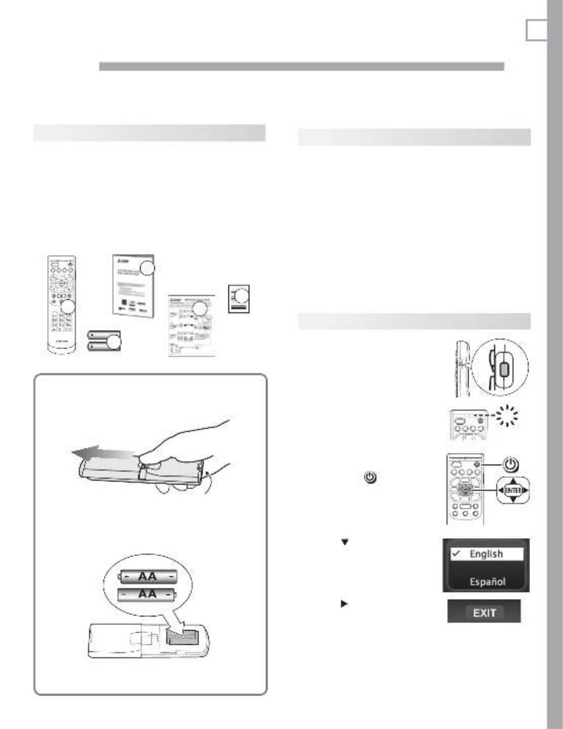
First-Time Power-On
Confirm that the remote
1.
control is in
TV
mode.
Press the side button •
once to light the mode
indicator and confirm
that
TV
mode is active.
To change, press the •
side button additional
times to activate
TV
mode.
GU IDE ME NU I N FO B A CK
TV
Aim the remote control
2.
at the TV and press the
POWER
key . Wait for the
Welcome screen.
GU IDE ME NU I N FO B A CK
Press
3.
if you wish to
change the menu language
to .Español
Press
4.
to highlight EXIT.
Press
ENTER
to clear the
menu.
1. Remote Control
2. Two AA Batteries
3. Basic Owner’s Guide
4. HDTV Quick-Setup Guide
5. Product Registration Card
AA
AA
2
3
4
GUI D E MEN U INF O BACK
A CTI VIT Y
1
5
Package Contents
Please take a moment to review the following list of
items to ensure that you have received everything.
Remote Control Batteries
Remove the remote control back cover.1.
Emitter bulb
Load the batteries, making sure the polarities 2.
(+) and (-) are correct. Insert the negative (-)
end first.
Slide the cover back into place.3.

8 1. Basic Setup and Operation
Remote Control
GUIDE M E N U I NFO BACK
ACT IVITY
Powers TV on or off.
Side button sets the control mode
for the type of device to operate. Set
mode to
TV
for normal TV viewing.
Number/letter keys
Channel tuning, page 12
MORE
Displays a menu showing addi-
tional functions for the number
keys.
For the •
MORE
menu in TV mode,
see below.
With remote control programmed •
for other device types, page 58.
The
MORE
menu in other modes is
specific to the device type.
For CEC-enabled devices, • page 67
CHANNEL UP
VOLUME UP
Record/Playback controls for external devices
When remote control is programmed, page 58
HDMI control, page 69
837 Series: NetCommand, page 48
VCR
CABL/SAT
TV
DVD
AUDIO
Control-mode indicator for device
type to control. Use the side button to
change.
MUTE
VOLUME DOWN
LAST
.
Goes to the previously tuned channel.
CHANNEL DOWN
TV Controls
Note: To operate other audio/video
devices using the TV’s remote
control:
• SeeAppendix A, “Programming the Remote
Control.”
• ForHDMIdevicescompatiblewiththeTV’s
HDMI Control feature, see Appendix C.
• 837 Series
See - page 45 for NetCommand IR “Learn-
ing” of device keys.
For use of specific keys with NetCom- -
mand-controlled devices, see “Special
Operation Methods,” page 48.
The menu in TV modeMORE
GUIDE
ChannelView listings, page 22
.
MENU
TV main menu, page 32
INFO
TV status (
page 23)
or TV help.
BACK
Steps back one menu; clears
the top menu or Status Display.
(
PAUSE
)
Freezes a broadcast TV picture.
—
CANCEL
Adds a separator when enter-
ing digital channel numbers.
Clears some menu entries.
ACTIVITY
Press to select a TV activity
and input. See page 21.
PAGE UP
ENTER
Selects a channel number or
menu item.
Navigation controls
PAGE DOWN
SLEEP
Sleep Timer, page 21
FORMAT
Picture shape (aspect ratio), page 24
MORE
Clears
the menu.MORE
CC
Closed captions, page 37
VIDEO
Video adjustments, page 35
AUDIO
Audio adjustments, page 36

1. Basic Setup and Operation 9
737 and C9 series.
Flip open cover to
use buttons on the
front panel.
TV Control Panel
Buttons on the control panel duplicate some keys on
the remote control.
Refer to • upper labels when no TV menus are dis-
played.
Refer to • lower labels when using TV menus or after
activating a special function.
System Reset
If the TV fails to respond to the remote control, the
control-panel buttons, or will not power on/off, perform
System Reset. Recent setting changes made before
using System Reset may be lost.
To perform System Reset, press and hold the
POWER
button on the control panel for ten seconds.
Panel-Lock Release
To • release the Panel Lock using the TV control
panel, press and hold the
ACTIVITY
button on the
control panel for ten seconds. If the TV is off, press
the
POWER
button to have it power on.
To activate the Panel Lock, use the • Lock menu,
page 44.
Controls on 737 and C9 series TVs. 837 series controls
are similar and are located next to the
STATUS
indicator.
TV Controls, continued
If You Power Off the TV by Mistake
1. Press
POWER
again, within about 60 seconds, to
have the TV come back on immediately.
2. If the status indicator starts rapidly blinking
green (about 60 seconds after you shut off
power), wait a few moments for the status indi-
cator to stop blinking and press
POWER
to turn
the TV on again.
Key Off Steady On Slow Blinking Fast Blinking
LED Color TV Condition
None TV is powered off. Normal operation.
Green TV is powered on. Normal operation.
Green TV powered off, auto-on TV Timer is set.
Normal operation. TV can be turned on at any time.
Green TV just powered off and lamp is cooling.
Sixty seconds after turning off TV, LED will start to blink. TV can be turned back on before blinking
starts or after blinking stops, but not while the indicator is blinking. Normal operation.
Yellow TV is too hot.
The TV will display a warning message and shut off if it overheats.
• Ambientroomtemperaturemaybetoohigh.TurnofftheTVandlettheroomtemperaturedrop.
• Clearblockedairvents.Ensureatleastafour-inchclearanceonallsidesoftheTV.
• Cleanthelamp-cartridgeairfilter.See“Lamp-Cartridge Filter Cleaning,” page 71.
Yellow Lamp access door is not secure or no lamp installed.
TV will not operate until lamp access door is secured. See Appendix D.
Red Lamp failure. Replace the lamp. See Appendix D.
Red TV may require service.
Turn off the TV and unplug the set from the AC power source. Wait one minute and then plug the set
back in.
If the red LED is still on, contact your dealer or a Mitsubishi Authorized Service Center. Go to www.mit-
subishi-tv.com or call 1-800-332-2119 to receive Authorized Service Center information.
STATUS Light
POWER
STATUS

10 1. Basic Setup and Operation
Setting Up Other Inputs
Connect your devices to the TV, making note of
1.
which TV input jack is used for each device. See
“TV Connections,” page 14, for recommendations.
Power on the devices to ensure detection.
2.
Power on the TV.
3.
The TV will display the screen New Device Found
for each new connection it detects Learn more
about Auto Input/Auto Output Sensing on the
opposite page.
Select the device type if the device is not recog-
4.
nized automatically.
Sample New Device
Found screen.
Important Note for NetCommand IR Users
837 Series. Be sure to select the correct device
type here. Although you can change the device type
later in the > menu, any “learned” Net-Inputs Name
Command IR codes will be erased when you make
the change.
837 Series.
5.
You can perform NetCommand IR
“learning” after selecting the device type or at a
later time when convenient. To perform now, high-
light NetCommand and press
ENTER
. See
“Initial
NetCommand Setup,” page 47 or “Setting Up A/V
Receiver Control,” page 52.
Press
6.
BACK
to close the screen. New Device Found
The TV will then display the New Device Found
screen for the next connection it finds.
Using the ANT (Antenna) Input
If using an antenna or direct cable service (no cable
box), connect the incoming coaxial cable to the TV’s
ANT
input. Refer to page 18.
You must save channels to memory with a channel scan
to enable reception of all available high-definition and
standard-definition digital channels. The channel scan
will search for channels available locally. If you skip this
step, the TV will receive only analog channels.
Memorizing Channels with Channel Scan
For the ANT input
To start channel memorization
Power on the TV.
1.
Press
2.
MENU
and open the menu.Initial > Channel
Start channel memorization from the Initial > Channel
menu.
Press
3.
ENTER
to enter the menu.
Select
4.
Ant Air if connected to an
over-the-air antenna. Select Ant
Cable for direct cable.
Highlight
5.
Scan and press
ENTER
.
Channel memorization may take up
to 15 minutes to complete.
To stop channel memorization before completion,
press
CANCEL
.
Use the > menu (page 39) for Initial > Channel Edit
additional channel options, such as adding or deleting
channels from memory.
Setting Up TV Inputs

1. Basic Setup and Operation 11
About Auto Input Sensing/
Auto Output Sensing
This TV’s Easy Connect™ Auto Input Sensing feature
detects most connections automatically.
Auto Input/Auto Output Sensing for Most Devices
When you first connect a device, the TV will:
a. Detect the connected device and automati-
cally switch to it.
b. Prompt you to identify the device type.
c. Prompt you to perform NetCom-837 Series.
mand set-up for the device, if available.
d. Repeat these steps for other newly detected
devices.
Which Jacks Trigger Auto Sensing?
TV Jacks and
Auto Sensing
Auto Input
Sensing
Auto Output
Sensing
No Auto
Sensing
Y/VIDEO
(detected as
composite video)
Y/VIDEO
plus
Pb
(detected
as component video)
HDMI
USB
(837 series)
DIGITAL AUDIO OUTPUT
(orange jack)
AVR AUDIO OUTPUT
(
red jack)
ANT
(Antenna)
IR NetCommand Output
(837 series)
The TV may not detect an HDMI device when
the device is powered off
. Detection will
occur when the device is next powered on.
When You First Connect a Device
Most Device Types.• Select the device type from
the on-screen list. The device type you select here
will appear as a device icon in the Activity menu.
A/V Receiver•
The TV can detect audio connections on the -
DIGITAL AUDIO OUTPUT jack and the right (red)
AVR AUDIO OUTPUT jack.
For an HDMI A/V receiver, select - from AVR
the list of device types if the A/V receiver is
not recognized automatically.
HDMI CEC Devices Compatible with the TV’s •
HDMI Control Feature.
Compatible CEC-
enabled HDMI devices are often recognized auto-
matically by the TV.
HDMI Control may allow you
to control some functions of a CEC-enabled device.
See Appendix C, “HDMI Control of CEC Devices.”
New Device Found screen for a device with HDMI
control enabled. Select On to enable the TV’s CEC
control of the device. In some cases, as in the
example above, you will also be prompted to select a
device name.
Tips on Auto Sensing
Choose a different name for each input.•
The antenna input (•
ANT
) is never detected,
although you can turn off the unused antenna
input in the > menu.Inputs Name
Change the device type displayed in the • Activity
menu by using the menu (page Inputs > Name
40).
837 series.• Any “learned” NetCommand IR
codes will be erased if you change the device
type in the menu.Inputs > Name
Reactivating Auto Input Sensing
for an HDMI Input
When you disconnect an HDMI device, Auto Input
Sensing is disabled until you perform these steps.
Disconnect the HDMI device.
1.
Delete the removed HDMI device in the
2.
Inputs >
Name menu (see “Removing an HDMI Device,”
page 69).
Connect the new device and the
3.
New Device
Found screen will display.
Setting Up TV Inputs, continued

12 1. Basic Setup and Operation
Selecting an Input to Watch
Press
1.
ACTIVITY
.
Press
2.
and to highlight an input.
Press
3.
ENTER
to switch to the input.
Watching Broadcast TV
TV Connected to an Antenna, Direct Cable, Cable
Box, Set-Top Box, or Satellite Receiver
Select an input to watch from the
1.
Activity menu’s
Watch TV group.
Note: For more about the menu, see page 21.Activity
Activity menu, antenna input selected
Tune to a channel on the
2. ANT
input using any of
these methods.
Enter the channel number using the number •
keys on the remote control and press
ENTER
.
For a two-part digital channel, such as 3-1,
press
3
—
CANCEL
1
to enter a dash (separator).
Press •
CHANNEL UP /CHANNEL DN
(
+
/
–
) to change
channels one channel at a time.
Press •
(LAST)
to switch back to the previ-
ously tuned channel.
Antenna or Direct Cable Only.• Press
GUIDE
to
display ChannelView channel listings, highlight
a channel number, and press
ENTER
to tune.
Watching DVDs or Videos
TV Connected to a DVD Player, DVR, or VCR
Press
ACTIVITY
and select a movie source from the
Activity menu. If you named devices during Auto Input
Sensing, select the input from the group.Watch Movie
Activity menu, DVD input selected
Basic TV Operation
TV Tips
Turning the TV On or Off
Point the remote control at the front of the TV •
and press the
POWER
button.
Press the •
POWER
button on the TV control
panel.
If You Turn Off the TV by Mistake
Press •
POWER
again, within about 60 seconds,
to have the TV come back on immediately.
If the status indicator starts rapidly blinking •
green (about 60 seconds after you shut off
power), wait a few moments for the status indi-
cator to stop blinking and press
POWER
to turn
the TV on again.
Controlling Sound Volume
Press •
VOLUME
UP/VOLUME DN
to adjust the sound
level.
See also • “Controlling A/V Receiver Sound
Volume” on page 22.

1. Basic Setup and Operation 13
Making Picture Adjustments
To get the best picture under different viewing con-
1.
ditions, set the Picture Mode before changing other
video settings. See page for more.35
a. Press
MENU
and go to the Adjust > Picture >
Picture Mode menu.
b. Make one of these selections:
Name When to Use
Brilliant
Under bright light
Game
With gaming consoles
Bright For most daytime viewing
Natural For most nighttime viewing
c. Press
MENU
to clear the menu.
Press
2.
MORE
.
Press
3.
8
(VIDEO).
Press
4.
to display the name of the adjustment
you want.
Press
5.
to make the adjustment.
Additional picture adjustments are described on pages
33 and .34
Audio Settings
Changing the Audio Output
To switch audio output from the internal TV speakers to
a connected external sound system or headphones:
Press
1.
MORE
.
Press
2.
9
(AUDIO).
Press
3.
until the Speakers option is displayed.
The Speakers option will display only if a connec-
tion has been detected on one of the TV’s audio
outputs.
Press
4.
to switch between TV and either AV
Receiver Headphones or .
Changing Audio Settings
Press
1.
MORE
.
Press
2.
9
(AUDIO).
Press
3.
to display the name of the adjustment
you want.
Press
4.
to change the setting.
Other TV Features
Activate Audio Lock to control your sound system •
with the TV’s remote control left in
TV
mode. See
page 59.
To set the TV Clock see • page 38. Set the TV
Clock if you plan to use the TV Timer (page 38) or
ChannelView (page 22) features.
To set parental controls, see the • Lock menu, page
42.
To change the input names that appear in the •
Activity Inputs menu, see > Name options, page
40.
3D Video.• See page 25.
To program the remote control to operate other •
A/V devices, see Appendix A, “Programming the
Remote Control,” page 58.
To control compatible devices using HDMI CEC •
control, see Appendix C, “HDMI Control of CEC
Devices,” page 67.
837 Series.• To view still and moving digital camera
images on the TV, see “Camera Images and Music
Files,” page 28.
837 Series.• To control A/V devices with NetCom-
mand, see chapter 5, “NetCommand IR Control for
Most Devices” on (page 45).
Basic TV Operation, continued
Other Information
TV Care
Lamp Cartridge.• When the lamp cartridge needs
replacement, replace the lamp yourself and save
the cost of a service call. See Appendix D for
instructions.
General Cleaning.• See “Cleaning Recommenda-
tions,” page 72.
Assistance
For troubleshooting, service, and product support, •
see Appendix E, page 73.
For warranty information, see the TV warranty on •
page 84.

14
2TV Connections
Auto Input Sensing
The TV’s Auto Input Sensing feature automatically rec-
ognizes most connections and prompts you to identify
the type of device connected. See page 11 for more on
Auto Input Sensing.
Connection Types
Use the connection types available on your input
devices that will give the best video quality. For
example, choose HDMI over component video, and
choose component video over composite video.
Picture Quality
For best picture quality, route signals directly from the
input device to the TV whenever possible.
Surround Sound
For best surround sound audio quality, route audio-
signal cables or HDMI cables from the source device
directly to your A/V receiver or sound system.
IMPORTANT
Accessory items such as cables, adapters,
splitters, or combiners required for TV
connections are not supplied with the TV.
These items are available at most electronics
stores.
Before You Begin

2. TV Connections 15
Inputs and Outputs
1 2 3
HDMI
AVR
AUDIO
OUTPUT
L
R
Pb
Y/ VIDEO
Pr
Pb Pr
INPUT 2
INPUT 1
DIGITAL
AUDIO
OUTPUT
DVI/PC
AUDIO
(480i / 480p / 720p / 1080i)
L
R
LR
INPUT
AUDIO
Y/ VIDEO
3D
GLASSES
EMITTER
ANT
32C
IR-NetCommand
Output
R
RS-232C control jack
offered on 837 series.
A readily accessible set of jacks is provided for a camcorder, game, or
other audio/video device.
837 Series. A fourth HDMI input is provided. If you connect a DVI
device to the HDMI input, use the nearby audio jacks to send sound
from the device to the TV.
1
5
8 34 92
6
10
HDMI
(page 17)
AVR
AUDIO
OUTPUT
(page 20)
DVI/PC INPUT
(page 18)
DIGITAL
AUDIO
OUTPUT
(page 20)
VIDEO
(composite
video, page 19)
Y Pb Pr
(component
video, page 17)
ANT
(page 18)
IR
–
NetCommand Output
(page 46)
Offered on 837 series.
3D GLASSES
EMITTER
(page 25)
7
Convenience Inputs
Main Connection Panel
Using an Audio-Only Device
Keep an unused RCA-style con-
nector in the
Y/VIDEO
jack while
using an audio-only device such
as an MP3 or CD player.
L-AUDIO-RY/VIDEO
Audio-only
device
Unused
RCA-style plug
(plug in first)
2.
1.
HDMI
(page 17)
USB
(page 28)
VIDEO
(composite video,
page 19)
Y Pb Pr
(component
video, page 17)
INPUT 3
AUDIO
L R
Pb
Y/ VIDEO
Pr
USB port and
HDMI 4 offered
on 837 series.
3
4
2
11

16 2. TV Connections
Inputs and Outputs, continued
1. ANT (Antenna)
Connect your main antenna or direct cable service (no
cable box) to
ANT
. The
ANT
input can receive digital
and analog over-the-air channels from a VHF/UHF
antenna or non-scrambled digital/analog cable source.
2. HDMI™ Inputs
(High-Definition
Multimedia Interface)
The HDMI inputs support uncompressed standard and
high-definition digital video formats and PCM digital
stereo audio.
Mitsubishi recommends you use category 2 HDMI
cables, also called high-speed HDMI cables, to connect
HDMI 1.3 source devices. High-speed category 2 cables
bring you the full benefits of Deep Color and x.v.Color.
These HDMI inputs can also accept digital DVI video
signals. To connect a device’s DVI output to the TV’s
HDMI input, use an HDMI-to-DVI adapter or cable plus
analog audio cables. Connect the analog audio cables to
the
DVI/PC INPUT AUDIO
jacks on the TV to receive left
and right stereo audio from your DVI device.
Use the HDMI inputs to connect to CEA-861 HDMI com-
pliant devices such as a high-definition receiver or DVD
player. These inputs support 480i, 480p, 720p, 1080i,
and 1080p video formats.
The TV’s HDMI inputs are compatible with many DVI-D
and HDMI computer video signals.
These inputs are HDCP (High-Bandwidth Digital Copy
Protection) compliant.
3. Y Pb Pr (Component Video)
Connect devices with component video outputs to this
jack. Use the adjacent
AUDIO R
and
L
jacks if you wish
to send audio to the TV.
4.
VIDEO
(Composite Video)
Connect a VCR, DVD player, standard satellite receiver,
or other A/V device to the TV. Use the adjacent
AUDIO
R
and
L
inputs if you wish to send audio to the TV.
5. 3D GLASSES EMITTER
Use this jack for the special IR emitter supplied with 3D
glasses. The emitter will send a signal that synchronizes
your 3D glasses with the screen display. See page 25
6. DVI/PC INPUT AUDIO
When connecting a DVI device to one of the TV’s HDMI
inputs, use these jacks for left and right analog audio.
7. AVR AUDIO OUTPUT
Use
AVR AUDIO OUTPUT
to send analog audio of the
current program to an analog A/V surround sound
receiver or stereo system. Digital audio from digital
channels and HDMI devices is converted to analog
audio by the TV for output on this jack. This is the only
audio connection needed to the TV if using an analog
A/V receiver or stereo system.
Headphones. These jacks can also be used for head-
phones that accept standard line level audio signals.
An adapter may be required.
8. DIGITAL AUDIO OUTPUT
This output sends Dolby Digital or PCM digital audio
to your digital A/V surround sound receiver. Incoming
analog audio is converted by the TV to PCM digital audio.
If you have a digital A/V receiver, in most cases this is the
only audio connection needed between the TV and your
A/V receiver.
9. IR–NetCommand Output
837 Series. Connect IR emitters to this jack to send
control signals to external IR remote-controlled devices.
10. RS-232C
837 Series. Use the RS-232C interface to receive
control signals from compatible home-theater control
devices. See www.mitsubishi-tv.com for a list of
control signals for this interface.
11. USB (837 Series)
The TV can read JPEG photo files and mp3 music files
from a USB device connected to the USB port.
HDMI Cable Categories
HDMI cables are available as Category 1 and Cat-
egory 2 types.
Category 2 Cables• (also called high-speed
HDMI cables). Newer, HDMI 1.3-compliant DVD
players, video games, and set-top boxes require
Category 2 cables, suitable for clock frequen-
cies up to 340 MHz or data rates of up to 10.2
gigabits per second. Use category 2 cables for
high-speed 1080p HD signals carrying extended
color encodings (i.e., 30 or more bits, also called
Deep Color). Category 2 cables are also suitable
for standard HDTV signals.
Category 1 Cables• (also called standard HDMI
cables). Category 1 cables may be unmarked.
They are suitable for standard HDTV 720p,
1080i, and 1080p signals with 8-bit color depth.
Use category 1 cables for clock frequencies up
to 74.25 MHz or data rates of up to 2.23 gigabits
per second.
2. TV Connections 17
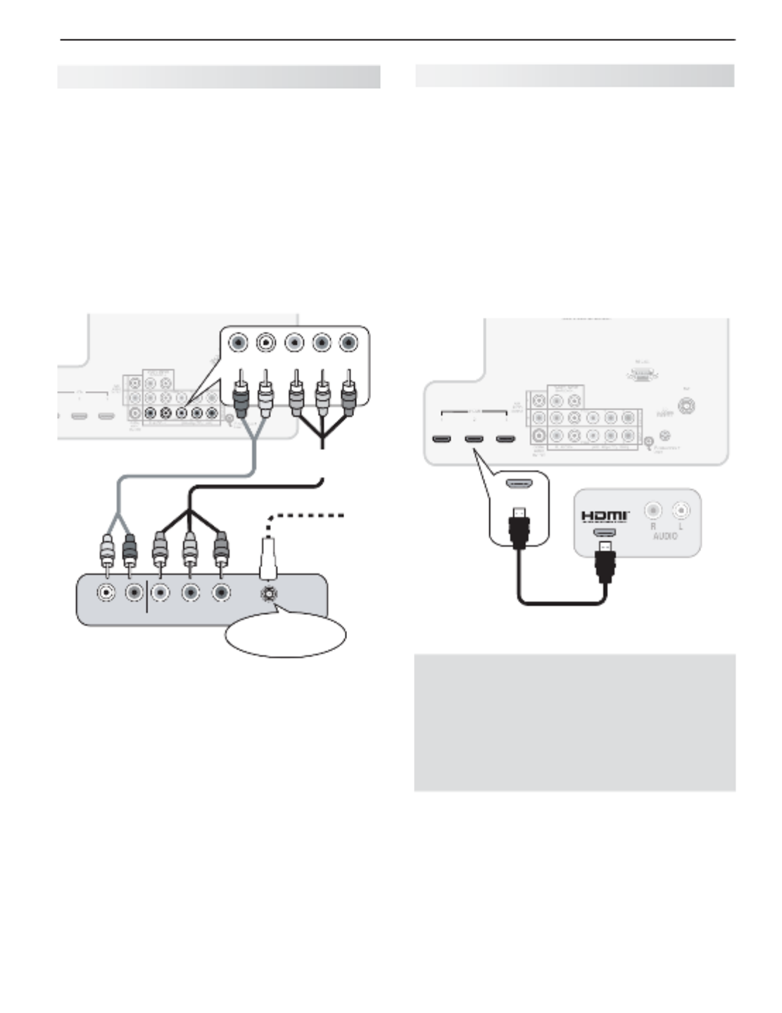
H
DMI Device
HDTV Cable Box, Satellite Receiver, DVD/
Blu-ray Player
Required: HDMI-to-HDMI cable.
Connect an HDMI cable from the TV back panel to the
HDMI device output. HDMI devices provide video and
audio through the single cable.
Mitsubishi recommends you use category 2 (high-
speed) HDMI cables to connect HDMI 1.3 source
devices. High-speed category 2 cables bring you the
full benefits of Deep Color and x.v.Color. See “HDMI
Cable Categories” on the opposite page for more on
HDMI cable types.
123
HDMI
Any HDMI
device
HDMI-to-HDMI
cable
TV main
panel
IMPORTANT
HDMI and Audio Signals
Digital Surround Sound: The TV’s HDMI inputs
can receive digital stereo audio signals only. To
hear digital surround sound from an HDMI device,
connect the device’s HDMI or digital audio output
directly to your A/V receiver. See the Owner’s
Guides for those devices for instructions.
Y Pb Pr Component Video Device
HDTV Cable Box, Satellite Receiver, DVD/
Blu-ray Player
If your source device has an HDMI output, use the
connections for HDMI devices described on this page
instead of component video..
Required:
RCA-type component video cables
Left/right analog audio cables.
Note:
To hear digital surround sound, connect the digital
audio output from the device directly to your digital
A/V receiver.
Pb Pr
Y/ VIDEO
– – AUDIO
LR
Pb Pr
Y/ VIDEO
– – AUDIO
LR
PbY Pr
AUDIO
LR
Incoming from
cable service or
satellite dish
Component video
device
TV main panel
Audio
cables
Component
video cables
CABLE IN or
SATELLITE IN

18 2. TV Connections
DVI Video Device
Cable Box, Satellite Receiver, DVD Player
Connect DVI devices (digital only) to the TV’s HDMI
input jacks.
Required:
Analog stereo audio cables
DVI-to-HDMI cable or DVI/HDMI adapter and HDMI
cable
If you are using a DVI/HDMI adapter, it is important to
connect the adapter to the DVI device for best perfor-
mance.
Some devices require connection to an analog input
first in order to view on-screen menus and to select DVI
as the ouput. Please review your equipment instruc-
tions for DVI connectivity and compatibility.
Note: The HDMI connection supports copy protection
(HDCP).
DVI/PC
L
R
INPUT
AUDIO
123
HDMI
DVI OUT
AUDIO
R L
Digital DVI
device
TV main panel
Audio cables
DVI-to-HDMI
cable
Antenna or Cable TV Service
Connect the incoming cable to the TV’s
ANT
input.
ANT
ANT
INOUT
Cable TV
service
UHF
antenna
VHF
antenna
TV main
panel
Not recommeded. Other
connection types provide
better quality audio and video.
Direct cable (no cable box)
or
or
Older
cable
box
300-ohm-to75-
ohm combiner
(side view)
Y/ VIDEO
AUDIO OUT COMPOSITE
VIDEO OUT
LR
Y/ VIDEO
VCR or other
device with
composite
video output
TV main panel
Audio
cables
Composite
video cable
Composite Video Device
VCR or other device with composite video
output
Required:
Composite video cable (usually yellow)
Analog stereo audio cables.
2. TV Connections 19
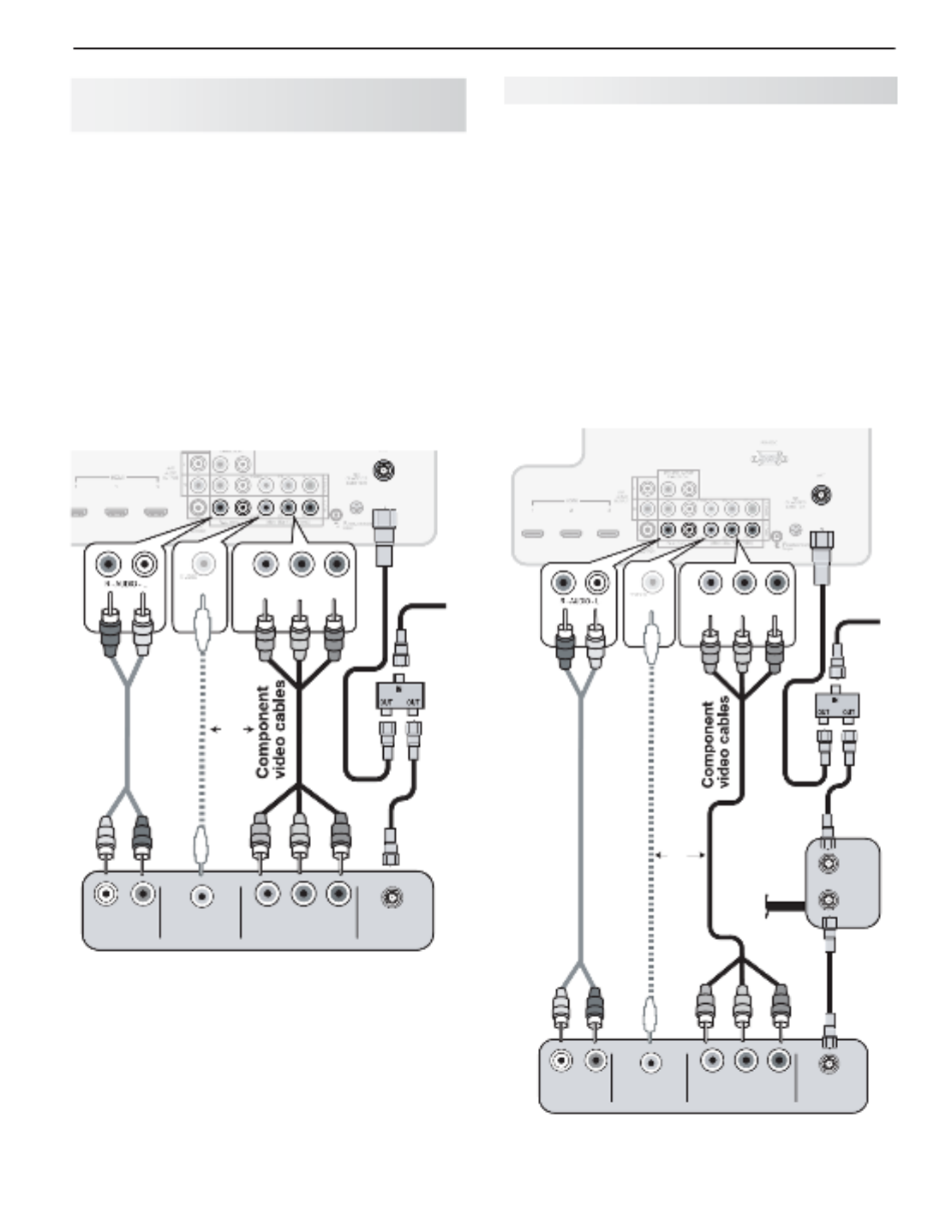
VCR or DVD Recorder to an
Antenna or Wall Outlet Cable
Required:
Two-way RF splitter
Two coaxial cables
Right and left analog audio cables
Component or composite video cables
Note:
• Usecompositevideoonlyifcomponent
video or HDMI are unavailable. For an
HDMI connection between the TV and
recorder, see page 17.
• Ifyourrecordingdevicehasananalog-only
tuner, you must use a digital converter box
to enable recording of digital broadcasts.
ANT
Y/ VIDEO
AUDIO OUT COMPOSITE
VIDEO OUT COMPONENT
VIDEO OUT
LR
Pb Pr
Y/ VIDEO
ANTENNA
IN
RF Splitter
DVD Recorder or VCR
Audio
cables
Composite
video cable
or
VCR or DVD Recorder to a Cable Box
Required:
Two-way RF splitter
Three coaxial cables
Right and left audio cables
Composite or component video cables
Video and audio cables required to connect the TV
to the cable box.
Notes: Use composite video if only if component video
or HDMI are unavailable. For an HDMI connec-
tion between the TV and recorder, see page 17.
When using this connection configuration, it is
possible to view live cable programs through the
recording device. For best picture quality always
view live cable programs directly from the TV input
connected to the cable box device.
ANT
Y/ VIDEO
AUDIO OUT COMPOSITE
VIDEO OUT
COMPONENT
VIDEO OUT
LR
Pb Pr
Y/ VIDEO
IN
OUT
ANTENNA
IN
RF Splitter
Cable
Box
Audio and
video from
cable box
directly to TV
or
DVD Recorder or VCR
TV main panel
Audio
cables
Composite
video cable
20 2. TV Connections
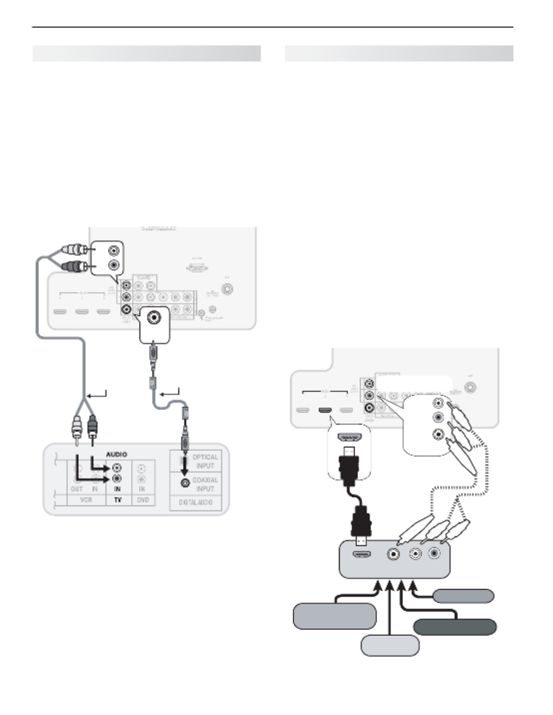
A/V Receiver
Most setups require either a digital audio cable or
analog stereo audio cables. To send audio from TV
channels received on the
ANT
input or devices con-
nected directly to the TV, you must use one of the
connections shown below. Usually, only one of these
connections is required.
The TV makes all audio available in digital and analog
formats:
Analog audio coming into the TV is available as •
output in digital stereo format on the
DIGITAL
AUDIO OUTPUT
jack.
Digital incoming audio is available as analog output •
on the
AVR AUDIO OUTPUT L
and
R
jacks.
L
R
DIGITAL
AUDIO
OUTPUT
COAXIAL
INPUT
L
R
AVR
AUDIO
OUTPUT
DIGITAL
AUDIO
OUTPUT
Digital coaxial cable
(for a digital A/V
receiver)
Stereo analog
cables
(for an analog
A/V receiver)
TV main panel
A/V receiver back panel
Note:
On rare occasions, an HDMI signal may be •
copy-restricted and cannot be output from
the TV as a digital signal. To hear these copy-
protected signals through the A/V receiver, use
the connection for an analog A/V receiver.
Check the A/V receiver’s Owner’s Guide for •
information concerning use of the digital input
and switching between digital sound and
analog stereo sound from the TV.
A/V Receiver with HDMI Output
Required: One HDMI-to-HDMI cable
This option allows you to view content from devices
connected to an A/V receiver. The A/V receiver can
send audio and video to the TV over a single HDMI
cable. You can use an HDMI connection as described
here in addition to an audio connection from the TV’s
audio output. The optional audio connection allows you
to hear, through the A/V receiver, devices connected to
the TV only, e.g., an antenna on the
ANT
input.
You may be able to use the TV’s remote control (in
TV
mode) to operate connected CEC-enabled HDMI
devices. Experiment with your equipment to determine
which functions are available to the TV’s remote control.
See Appendix C, page 67.
837 Series:
This setup allows you to use NetCom-
mand-controlled audio and video switching over the
HDMI cable. See “Case 3: Automatic Audio and Video
Switching via HDMI” on page 55.
To use NetCommand to supplement HDMI control of a
CEC-enabled A/V receiver, note the recommendations
under “More About Using an HDMI Connection,” page 55.
L
R
DIGITAL
AUDIO
OUTPUT
HDMI OUT
DIGITAL
AUDIO
L R
High-definition
DVD player DVD player
Cable box
VCR
1 2 3
HDMI
AVR
AUDIO
OUTPUT
DIGITAL
AUDIO
OUTPUT
L
R
A/V receiver
with HDMI
output
Optional analog or
digital audio
connection
TV main panel

21
Using TV Features
3
Selecting an Input
The menu lets you switch TV inputs. The inputs are Activity
organized into groups based on possible ways to use them.
Press the
1.
ACTIVITY
key.
Use
2.
to move through groups of TV inputs.
Use
3.
to select an input.
Press
4.
ENTER
to switch to the input.
To change the list of inputs shown in each activity group, •
see Inputs > Activity, page 40.
To assign or change the names of input icons, use the •
Inputs > Name menu, page 40.
Sleep Timer
The Sleep Timer turns the TV off after the length of time you set.
To set the TV to turn on at a certain time of day, see the menu on page Initial > Timer
38.
Setting the Sleep Timer
Press
1.
MORE
on the remote control. The TV’s menu will display.MORE
Press
2.
CANCEL
(SLEEP) repeatedly to increase the time in 30-minute increments.
The maximum is 120 minutes.
Press
3.
BACK
or wait five seconds without pressing any keys for the message to dis-
appear.
Viewing or Changing the Sleep Timer
Press
1.
MORE
.
Press
2.
CANCEL
(SLEEP).
Press
3.
CANCEL
(SLEEP) additional times to change the number of minutes before the
TV powers off.
SLEEP
With the MORE menu
displayed, press the
CANCEL key on the
remote control to
activate/deactivate the
Sleep feature.

22 3. Using TV Features
ChannelView Channel Listings
ChannelView. Programs for the tuned channel are
listed on right side of screen.
ChannelView™ shows memorized channels on the
ANT
input. It displays channel names and program informa-
tion for digital channels as sent by broadcasters or your
local cable service provider (information may be incom-
plete)
.
No program information is displayed for analog
channels.
Note: You must set the TV Clock (page 38)
t
o receive
ChannelView listings for the current channel.
Using ChannelView
Feature Instructions
Receive updates for a
digital channel.
Press 1. to
highlight a channel
number.
Press the 2.
INFO
key
(the screen may
briefly go blank).
Display/hide ChannelView
listings from the ANT
input.
GUIDE
Scan channels one by one. Hold or
Scan channels quickly.
Hold
PAGE UP/PAGE DN
Jump to listings for a spe-
cific channel.
Enter the channel 1.
number.
Press 2.
ENTER
.
See more of the program
description for the current
channel (if available).
INFO
Tune to the highlighted
channel.
ENTER
Redirecting Audio Output
Selecting an Audio Output Device
Press
1.
MORE
and then
9
(AUDIO)
.
Press
2.
to show the Speakers option. The Speak-
ers option will display only if there is a recognized
audio device on an audio or HDMI output.
Press
3.
to select either AV Receiver, Head-
phones, or TV.
Disconnecting an Analog A/V Receiver
When you disconnect an analog A/V receiver, change
the Speakers setting to TV to hear sound from the TV
speakers. Change the setting using the remote con-
trol’s
MORE
>
9
(AUDIO
)key or the Adjust > Audio >
Speakers menu.
Controlling A/V Receiver Sound
Volume
Use one of the methods below to control sound volume from
an A/V receiver.
With a Standard TV Setup
Recommended Method:• Program the TV’s
remote control for your A/V receiver and enable the
Audio Lock feature. See page 59.
Program the TV’s remote control for your A/V •
receiver and set the TV remote control’s mode to
AUDIO
. Return the control mode to
TV
to control the
TV.
Use the remote control that came with the A/V •
receiver.
With HDMI Control (CEC-Enabled HDMI
A/V Receiver)
The TV’s remote control may control some functions of
the A/V receiver. See Appendix C, “HDMI Control of
CEC Devices,” page 67.
With NetCommand IR Control
837 Series. Set up NetCommand control of the A/V
receiver’s volume functions in the > menu. Inputs AVR
The TV’s remote will then control A/V receiver volume.
See page 52.

3. Using TV Features 23
Press the
INFO
key to see
the on-screen status
display. The most
common displays are
shown here.
Sample information
from the on-screen
status display
1. Current Input
2. Audio Indicator. Key:
TV speakers External sound system
Headphones Mute
3. Channel number (antenna source only)
Digital channel includes major and sub-channel
numbers.
4. Digital channel name (if broadcast); antenna
source only.
5.
V-Chip rating
Antenna source only for digital signal•
Antenna or •
VIDEO
composite jack for
analog
signal
6. Program name (if broadcast); digital source only
7. Program description (if broadcast); digital
source,
antenna only. Press the
INFO
key additional
times to see more of the description.
8. Sleep Timer remaining time
9. Day and time
10. Signal type being received
11. Screen format in use
12. Program Audio indicator (antenna source only)
Digit•
al source: Stereo, Surround
Anal•
og source:
Stereo, Stereo SAP, SAP
13. Available language (digital source, antenna only)
14. Signal-strength indicator (digital source,
antenna only)
Status Display
5
402-101 KABC Monday Night Football
TV-PG DLSV St. Louis vs. Tampa Bay, played in Tampa for
1
3
2
46
7
Sleep 30 min
8
13
14
Tuesday 9:10 PM
Surround English
HD 1080i Standard
12
11
10
9
G UI DE M E NU I NF O BAC K
AC TI V ITY
About Channel Numbers
Channel Numbers for Over-the-Air Reception or
Reception by Direct Cable
Note: All signals are automatically converted to
1080p for display.
Standard-Definition Analog Channels
Cable 3
480i Stretch
Receiving Standard-Definition
Analog Signal (480i)
Cable Reception Channel 3
Standard-Definition Digital Channels
Ant 7-1 KABC-SD
SD 4:3 Stretch
Receiving Standard-Definition
Digital Signal (SD)
Over-the-Air
Antenna
Reception
Main Channel 7
Sub-Channel 1
High-Definition Digital Channels
Ant 7-1 KABC-HD
HD 16:9 Stretch
Receiving High-Definition
Digital Signal (HD)
Over-the-Air
Antenna
Reception
Main Channel 7
Sub-Channel 1

24 3. Using TV Features
TV Signals and Display Formats
Signal Definitions
480i: Older type of interlaced signals from the
ANT
input,
composite
VIDEO
, component
Y Pb Pr
, or
HDMI
jacks.
480p: Progressive-scan DVD signals on component
Y Pb
Pr
or
HDMI
jacks.
720p and 1080i: High-definition signals received through
component
Y Pb Pr
or
HDMI
jacks. These signals are
always 16:9 (widescreen).
1080p: High-definition signals from a PC or Blu-ray player,
HDMI inputs only.
SD 4:3: Standard-definition squarish-screen-format
signals from digital channels on the
ANT
input.
SD 16:9: Standard-definition widescreen-format signals
from digital channels on the
ANT
input.
HD 16:9: High-definition 16:9 widescreen signals from
digital channels on the
ANT
input.
This is a 16:9 widescreen TV suitable for images available
from HDTV and many DVDs. You can view older-style, squar-
ish images (4:3 aspect ratio) using one of the display formats
described on this page. Press the
MORE
key and then the
0
key (
FORMAT
) to cycle through available display formats.
The TV remembers the format you last used for each input.
DVD Image Definitions
Image information may be stated on the DVD case. Some
DVDs support both of the formats described below.
Anamorphic (or Enhanced for WideScreen TV)
Indicates DVDs recorded to show widescreen images prop-
erly on 16:9 TV sets using the TV’s Standard format mode
(recommended)
.
Non-Anamorphic (or 4:3, 1.33:1, Letter Box, or
Full Screen)
Indicates DVDs recorded for viewing on squarish TV
screens. They may be full screen (4:3 or 1.33:1) which
crops movies to fit the narrow TV, or letter box, which
adds black top and bottom bars.
TV Display Format Definitions
Standard: The full-screen format used by HDTV signals.
Use this format to display anamorphic DVDs with a 1.78:1 or
1.85:1 aspect ratio. Anamorphic DVDs with a 2.35:1 aspect
ratio are displayed correctly but with top and bottom black
bars. Squarish (4:3) images are stretched evenly from side to
side. Available for all signals.
Expand: Enlarges the picture to fill the screen by cropping
the top and bottom; useful for reducing the letter box top and
bottom bars of non-anamorphic DVD images.
Zoom: Enlarges the picture to fill the screen by cropping the
sides, top, and bottom to eliminate black bars.
480i/480p and SD 4:3 signals:• Eliminates top and bottom
bars on anamorphic DVDs with a 2.35:1 aspect ratio.
720p, 1080i, SD 16:9, and HD signals:• Eliminates bars
added to squarish 4:3 images.
Stretch: Stretches a squarish 4:3 image across the
screen to display the entire image with less distortion
than the Standard format.
Stretch Plus:
Similar to Stretch, but minimizes distor-
tion on the sides by expanding the picture to crop off
portions of the top and bottom. Use to adjust the
vertical position of the picture.
Narrow: Displays narrow 4:3 images in their original
shape. Adds black side bars to fill the screen.
Wide Expand: Enlarges the picture, cropping the image
on both sides. Removes or reduces black side bars added
to narrow images converted to 16:9 signals for digital
broadcast.
Note: All high-definition channels send widescreen
(16:9) signals, but not all programming was created for
the widescreen format. The broadcaster may stretch
the image or add side bars to fill the widescreen area.
Non-anamorphic or SD 4:3
Anamorphic DVD
Standard
Distorted.
Not recom-
mended.
Recommended
Expand
Recom-
mended for
letterbox. See
Note 1.
Distorted; not
recommended.
See Note 1.
Zoom
Distorted.
Not recom-
mended. See
Note 1.
Recommended
for anamorphic
2.35:1 images.
See Note 1.
Stretch
Recom-
mended for
standard
broadcasts.
See Note 1.
Distorted; not
recommended.
See Note 1.
Stretch
Plus
Recom-
mended for
standard
broadcasts.
See Note 1.
Distorted; not
recommended.
See Note 1.
Narrow
See Note 1 Distorted; not
recommended.
See Note 1.
Note 1: Available for 480i, 480p, and digital SD 4:3 signals only.
Original Signal Display Formats
SD 16:9 or
HD Digital
720p, 1080i,
1080p Signal
Wide
Expand
Recommended to re-
move side bars.
Zoom
Recommended to re-
move bars from the top,
bottom, and sides.
TV Display Formats. Press the
MORE
key and then
repeatedly press the
0
key (
FORMAT
)
to see the displays
available for the current program. Press the
INFO
key to see
the name of the display format in use.
Original
Signal
TV
Display

3. Using TV Features 25
This section provides Instructions for viewing 3D
video using 3D glasses and the TV’s 3D feature. The
3D options are found in the menu Adjust > 3D Mode
described on page 34.
Initial Setup
Check if your HDMI 3D video source device outputs
1.
a 1080p 60 Hz signal. This information will be
needed when you assign an input name in the New
Device Found screen.
If your 3D glasses came with an emitter box,
2.
connect the emitter box to the
3D GLASSES
EMITTER
jack. Place the box in front of the TV
where there is clear path to the glasses.
123
HDMI
AVR
AUDIO
OUTPUT
L
R
Pb
Y/ VI DEO
Pr
Pb Pr
INPUT 2
INPUT 1
DVI/PC
(480i / 480p / 720p / 1080i)
LR INPUT
AUDIO
Y/ VI DEO
3D
GLASSES
EMITTER
ANT
RS-232C
IR-
NetCommand
Outpu t
R
3D
GLASSES
EMITTER
Power on the TV and the source device.
3.
Connect the source device to the TV’s HDMI input.
4.
When the
5.
New Device Found screen displays,
name the input according to the table below.
The signal type and choice of name are important
because the TV will process the video signal
differently depending on the name you assign.
If your source device is a Blu-ray disc or game
console, the signal must be 1080p at 60 Hz.
Source
of 3D
Video
3D Video Signal Assign
Name
Computer Recommended: 1080p 60 Hz
(1920 X 1080). The image will fill
the TV screen.
Other 60-Hz computer video
signals compatible with the TV
will display with black bars. See
“Computer Display Formats” on
page 27.
PC
Any other
3D video
source
To see 3D video, the signal must
be 1080p 60 Hz
Any
other
name
Press
6.
BACK
to close the screen.New Device Found
Watching 3D Video
Note: 3D glasses are required.
Press
1.
ACTIVITY
.
Highlight the icon for the 3D video device and press
2.
ENTER
.
Press
3.
MENU
and select the Adjust > 3D Mode
menu.
Select
4.
On On. The setting will be memorized for
the current input when you exit this menu.
Use the Adjust > 3D Mode menu to enable 3D video.
Press
5.
BACK
to close the menu.
If the image does not appear correct
6.
(e.g., objects
appear to be moving in instead of out),
open the
Adjust > 3D Mode menu and set to Glasses L-R
Reverse.
To Watch Regular (non-3D) Video
The setting is memorized for each input. 3D Mode
When you want to watch non-3D video on the input
selected above, open the menu and Adjust > 3D Mode
set to 3D Mode Off.
3D Video
Important Note About 3D Images
To display 3D images, Mitsubishi Home Theater DLP
TVs require that source devices support checker-
board display formats for 3D gaming or 3D cinema
content. A 3D standard format does not currently
exist for Blu-ray or DVD prepackaged media. Future
3D standards may be incompatible with Mitsubishi
Home Theater DLP TVs. Please visit mitsubishi-tv.
com for updates and information.
26 3. Using TV Features
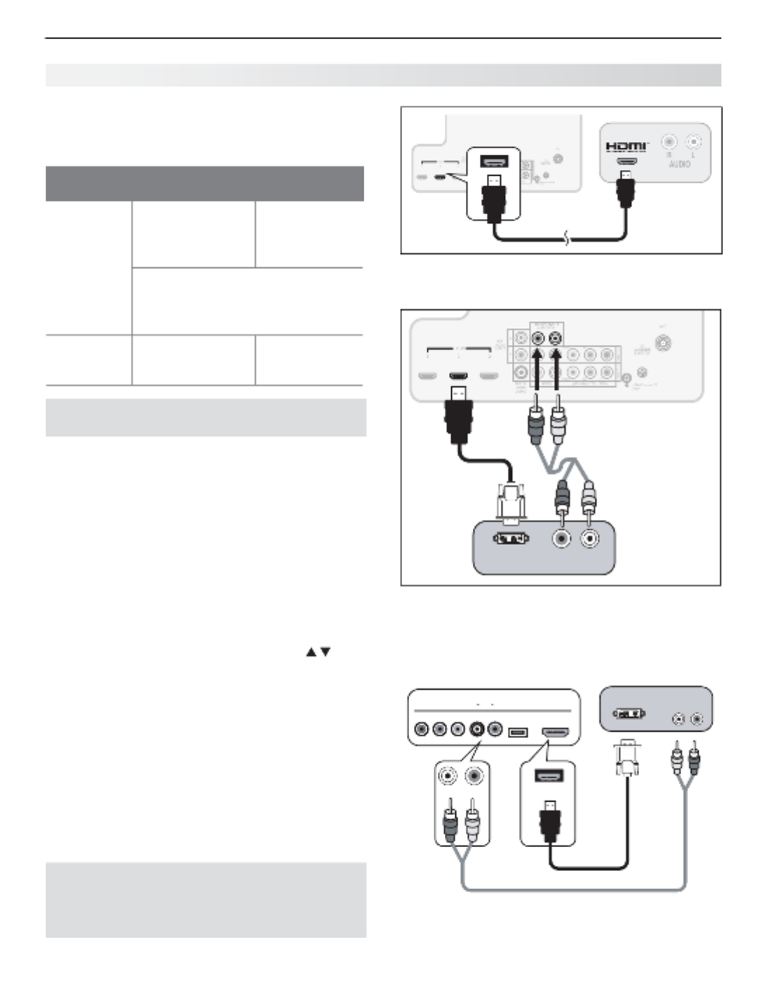
Connecting a Computer to the TV
Use one of the connection methods listed below based
on your computer’s video output.
Computer
Video Output
Video Connection Audio
Connection
Digital DVI DVI-to-HDMI cable
or an HDMI cable
with an HDMI-to-
DVI adapter
Stereo audio
cables
Note: If the computer’s audio output
is a single mini jack, a mini audio-to-
RCA-male “Y” adapter cable is also
required.
HDMI HDMI-to-HDMI
cable
No additional
audio connec-
tion is required.
IMPORTANT
This TV accepts digital computer signals only.
Connect the computer’s digital signal output to one
1.
of the TV’s
HDMI
jacks. See the connection dia-
grams for the method suited to your equipment.
Connect the computer’s audio output using one of
2.
these options:
• FordigitalDVIsignals,connectanalogleft/right
audio to the TV’s
DVI/PC INPUT AUDIO
jacks.
• ForHDMIsignals,noadditionalaudioconnec-
tion is required.
Power on the TV and computer. The TV will detect
3.
the connection and display the New Device Found
screen.
In the
4.
New Device Found screen, press to
highlight in the list of device types. It is impor-PC
tant to use the name so that the TV processes PC
the video signal correctly.
Press
5.
BACK
to close the screen.New Device Found
123
HDMI
Computer
with HDMI
audio and
video output
TV main
panel
An HDMI-to-HDMI connection carries all video and
audio on a single cable.
DVI/PC
L
R
INPUT
AUDIO
123
HDMI
DVI/PC
L
R
INPUT
AUDIO
123
HDMI
DVI OUT
AUDIO
R L
Computer with
DVI and stereo
audio outputs
TV main panel
1.
1.
2.
2.
A DVI connection from a personal computer requires a
separate audio connection. A computer connected to
the TV main connector panel is shown above.
USB HDMI 4
INPUT 3
AUDIO
L R
Pb
Y/ VIDEO
Pr
HDMI 4
DVI OUT AUDIO
RL
Computer with DVI and
stereo audio outputs
TV convenience inputs
HDMI-to-DVI cable
837 Series: Computer with DVI output connected to
the convenience panel.
Note: If your computer provides digital audio out-
put (coaxial or optical), you can connect it
directly to a digital A/V receiver and bypass
the TV.
Using the TV with a Personal Computer

3. Using TV Features 27
Tip
Set the computer’s screen saver to display a pattern
after several minutes of inactivity. This acts as a
reminder that the TV is powered on and the lamp
is in use. The lamp is in use whenever the TV is
powered on, even if the screen appears dark.
Computer Video Adjustments
Power on the computer.
1.
Select
2.
PC from the menu. To do this, Activity
press
ACTIVITY
to open the menu, move the Activity
highlight to the PC icon, and press
ENTER.
Working from the computer, change the resolution
3.
of the computer image. View the computer image
on the TV and maximize the computer resolution
while maintaining a suitable aspect ratio for the
image.
Perform TV video adjustments.
4.
Press
MORE
then press
8
( ) repeatedly VIDEO
to access video-adjustment options.
The following additional adjustments
are available for computer video:
Horiz Position (Horizontal Position).
Manually adjust the horizontal
position.
Vert Position (Vertical Position).
Manually adjust the vertical position.
Press
5.
MORE
then press
0
(FORMAT)
repeatedly to find the picture format
(aspect ratio) best suited to the image.
See the chart on this page showing
how different computer resolutions
can be displayed on the TV.
Image Resolution
Your Mitsubishi TV can display the resolu-
tions shown in the chart from standard
VGA (640 x 480) through 1920 x 1080
signals at a refresh rate of 60 Hz.
In most cases, the computer will select
the best resolution match to display on
the TV. You can override this setting if you
wish. Refer to your computer operating
system’s instructions for information on
changing the screen resolution.
You may need to restart the computer for
changes to take effect.
Using the TV with a Personal Computer
Distortion in Computer Images
Computer images may show distortion
when viewed on the TV, e.g., lines that
should be straight may appear slightly
curved.
Computer Display Formats
Press
MORE
then press
0
(FORMAT) repeatedly to cycle through the
TV displays available for your computer’s video signal.
Computer Signal
As Displayed on TV Screen
Original Format 4 X 3
Standard
16 X 9
Standard Zoom
VGA
640 X 480
WVGA
848 X 480
SVGA
800 X 600
WSVGA
1064 X 600
Original Format Standard Zoom
XGA
1024 X 768
PC 720p
1280 X 720
WXGA
1360 X 768
SXGA
1280 X 1024
Original Format Standard Reduce
PC 1080p
1920 X 1080

28 3. Using TV Features
The USB Media Player Menu
Displaying the Menu
Back up the data on your USB drive before con-
1.
necting it to the TV. Mitsubishi is not responsible
for any file damage or data loss.
Connect your USB drive to the TV’s USB port.
2.
The menu displays while files USB Media Player
are being read. Wait until icons appear in the menu
before continuing.
USB HDMI 4
INPUT 3
AUDIO
L R
Pb
Y/ VIDEO
Pr
837 series TVs can read photo and
music files from the USB port.
From the USB Menu you can:
3.
Activate any of the
menu options
Highlight an icon and press
ENTER
.
Display the Activity
menu.
Press
ACTIVITY
.
Press again to
clear.
Display the main
menu.
Press
MENU.
Press again to
clear.
Display status for the
file source.
Press
INFO.
Press
BACK
to
clear.
To resume use of the USB port after switching the
4.
TV to a different input, press
ACTIVITY
, choose View
Photos, and select the USB port.
Playing a Slide Show or Playlist
Use these keys while playing a slide show or playlist.
or
ENTER
Replays the slide show or playlist.
Pauses a slide show or playlist.
Stops a slide show or playlist.
Displays the previous or next slide.
Plays the previous or next track.
GUIDE
Rotates an image clockwise in 90˚ incre-
ments.
BACK
Displays the menu.USB Media Player
MENU
Displays the main menu and stops play.
ACTIVITY
Displays the menu and stops play.Activity
INFO
Displays slide name or track name. Press
BACK
to clear.
IMPORTANT
Always stop playback with (
STOP
) or change
to a different TV input before disconnecting your
USB device.
837 Series TVs Only
The TV can read photo or music files from a USB •
device. Photos must be in JPEG format and music
files must be in mp3 format. To play music files
while displaying a photo slide show, see “USB
Media Setup Menu” on the opposite page.
The TV can display files of still or moving images •
from a camera through the
Y/VIDEO
port.
Camera Images and Music Files
The TV can read JPEG files as created by the
camera. If you edit a picture file on a computer
and resave the image, the TV may be unable to
read the resaved file.
3. Using TV Features 29
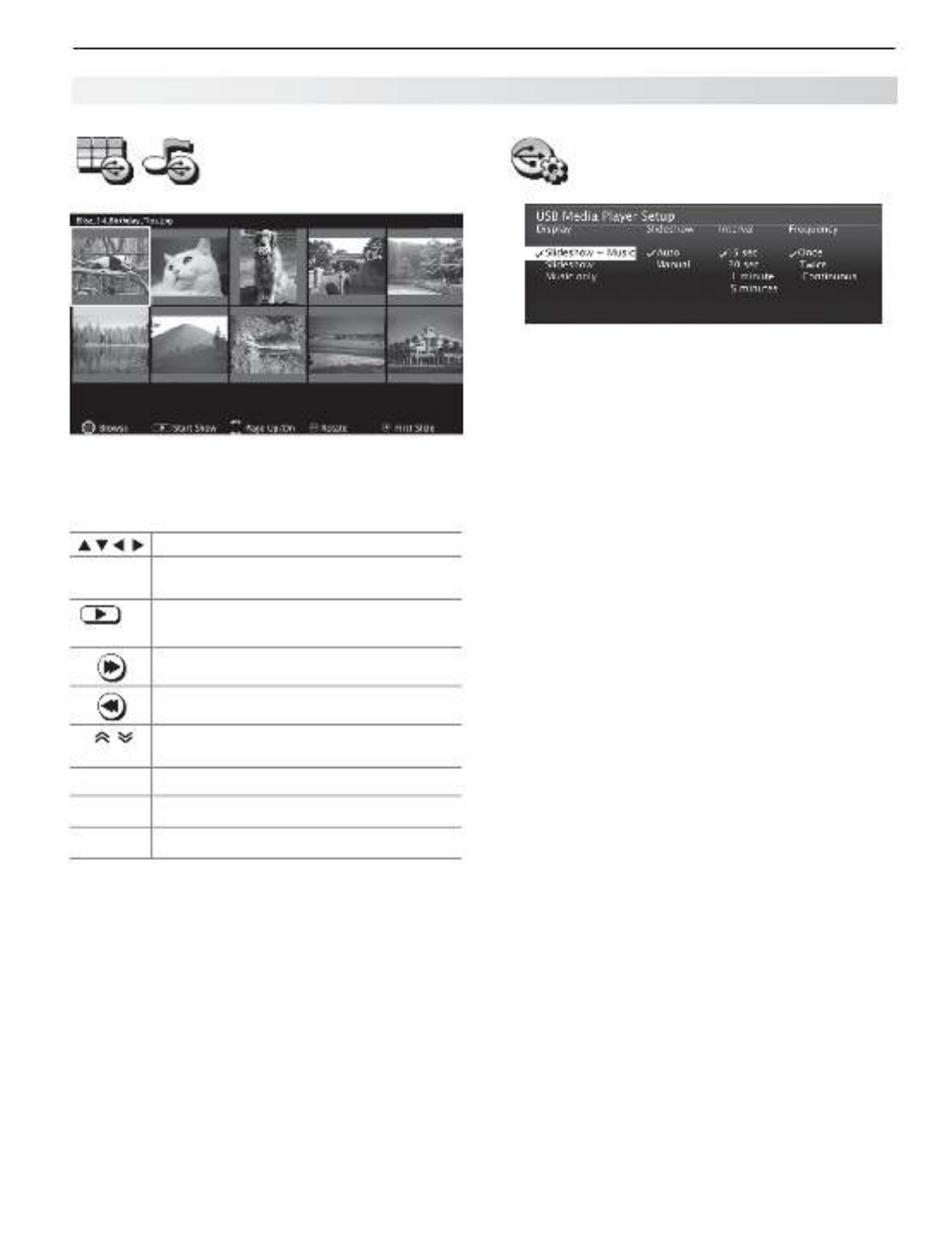
Thumbnail and Playlist
Menus
JPEG Thumbnail Menu
Use these keys while viewing JPEG thumbnail images
or the music tracks in a playlist.
Moves the highlight from item to item.
GUIDE
Rotates a thumbnail clockwise in 90˚
increments
or
ENTER
Plays the slide show or playlist starting
with the highlighted item.
Selects the last item on the current page.
Selects the first item on the current page.
PAGE UP/DN
Displays the next or previous page of
items.
BACK
Displays the menu.USB Media Player
MENU
Displays the main menu.
ACTIVITY
Displays the menu.Activity
Notes on Using the USB Port
• TheTVignoresallcommandswhilereadingfiles.
Wait
until the icon appears highlighted and in full Play
color before continuing.
• Largefilesorhigh-capacitystoragedevicesmaytakea
long time to display.
•
The TV can read files up to 10 MB in size with a
maximum of 2,500 files stored on the device. The
FAT16 or FAT32 file system is recommended.
• UseaUSBdriveinsteadofacardreader.
• BackupthedataonyourUSBdrivebeforeconnect-
ing it to the TV. Mitsubishi is not responsible for any
file damage or data loss.
Note:
Some manufacturers’ devices may be incompat-
ible with the TV. If the TV is unable to display your
photos, you can:
• Transfer
files to a different USB device.
• Useyourdigitalcamera’scompositevideo
output. See page 30.
USB Media Setup Menu
Use the USB menu set up play of a slide Media Setup
show or playlist.
• IfJPEGimagefilesandmp3filesareontheUSB
device, choose:
Slideshow + Music -
Slideshow -
Music only -
Slideshow.• Select either or advance Auto Manual
for the slide show. During manual operation, press
ENTER
to advance to the next slide.
Interval.• For automatic advance, select the time
interval for display of each slide. The interval you
select here is the minimum time between slides;
actual time may be longer for larger files.
Frequency.•
For automatic advance, select the
number of times (frequency) to play the complete slide
show and/or playlist:
, , or .Once Twice Continuous
Press •
BACK
to close the menu and Media Setup
return to the menu.Media Player
Picture Files Compatible with the USB Port
• Stillimagesrecordedondigitalcamerasusingthe
Exchangeable Image File Format, version 2.1 (EXIF
2.1) standard for digital still cameras and Design
Rules for Camera File Systems version 1.0 (DCF 1.0)
• Someimagesopenedandresavedonacomputer
may not play back or may not display in the thumb-
nail list. This happens if the files were resaved in an
incompatible format.
• Fullpathfilenamescanbenolongerthan50char-
acters and must end in a .jpg extension. Only the
first 20 of the 50 characters will display.
Camera Images and Music Files, continued
30 3. Using TV Features
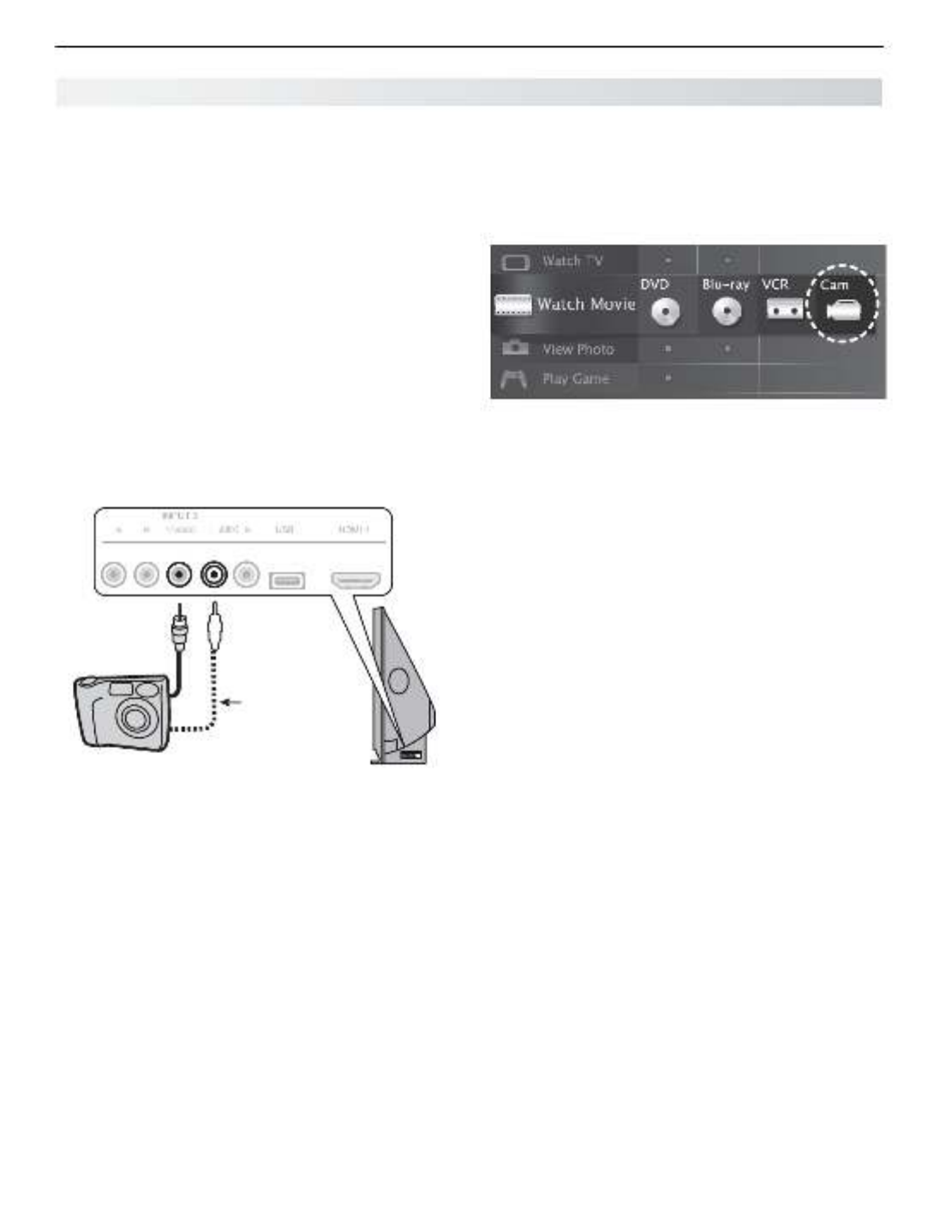
Photos and Moving Video
as Composite Video
Connect the camera to the TV using a composite video
cable if:
• YouareunabletoseeimagesusingtheUSBport.
•
You wish to view moving video from the camera.
Control the slide show or movie through the camera as
the TV’s menu will be unavailable. USB Media Player
The display resolution will be standard-definition (480i).
Refer to the owner’s manual supplied with the
1.
camera for instructions needed for this setup.
Set the camera’s output signal type to
2.
NTSC and
put the camera into playback mode.
With the camera still turned on, connect your digital
3.
camera’s composite video cable (usually yellow) to
the TV’s
Y/VIDEO
jack. To hear audio, connect the
camera’s audio output cable to the
AUDIO
L
jack.
Optional
Audio Cable
AUDIO
L
Y/ VIDEO
Camera connection using a composite video cable
When the
4.
New Device Found screen displays,
assign the name Camcorder.
Press
5.
BACK
to close the screen.New Device Found
Press
6.
ACTIVITY,
select , and Watch Movie > Cam
press
ENTER
.
If viewing photos, advance through the images
7.
manually or set the camera to advance automati-
cally.
Camera Images and Music Files, continued

3. Using TV Features 31
Introduction to Home-Theater Control
This TV offers a choice on home-theater-control systems. This summary offers some examples of the control
methods available using the . You may wish to use one or more of these methods in your TV’s remote control
home theater after completing Auto Input Sensing.
Source device connected directly to the TV
Remote Control Programming (Any Connection Type)
Program the remote control to operate the A/V device. To control the device, set
the remote control to the correct mode for the device type. See Appendix A, “ -Pro
gramming the Remote Control.” In the case of an A/V receiver, use the Audio Lock
feature, page 59.
Any Connection Type
TV
A/V
Device
CEC-Enabled HDMI Device (HDMI Connection Only)
See Appendix C, “HDMI Control of CEC Devices,” page 67. TV
CEC-Enabled
A/V Device
HDMI
Cable
837 Series: NetCommand IR Control (Any Connection Type)
Set up NetCommand IR control of the device’s keys as desired. See “IR Emitter
Placement,” page 46, and “Initial NetCommand Setup,” page 47.
Any Connection Type
TV
A/V
Device
Source device connected to an A/V receiver connected to the TV
CEC-Enabled HDMI A/V Receiver
The TV’s remote control may operate some functions of a connected A/V device.
You can switch to the device by selecting its icon in the TV’s menu. See Activity
Appendix C, “HDMI Control of CEC Devices,” page 67.
HDMI
Cable
HDMI
Cable
TV
CEC-Enabled
Source Device
A/V Receiver
837 Series: A/V Receiver with HDMI Output (no CEC)
Set up NetCommand IR control of the 1. A/V receiver’s keys as desired. See “IR
Emitter Placement,” page 46, and “Setting Up A/V Receiver Control,” page 52.
Set up NetCommand IR control of the 2. source device’s keys as desired. See
“NetCommand Control of a Device Connected to an HDMI A/V Receiver,” page
56.
TV
Any Con-
nection Type
Source
Device
A/V Receiver
HDMI
Cable
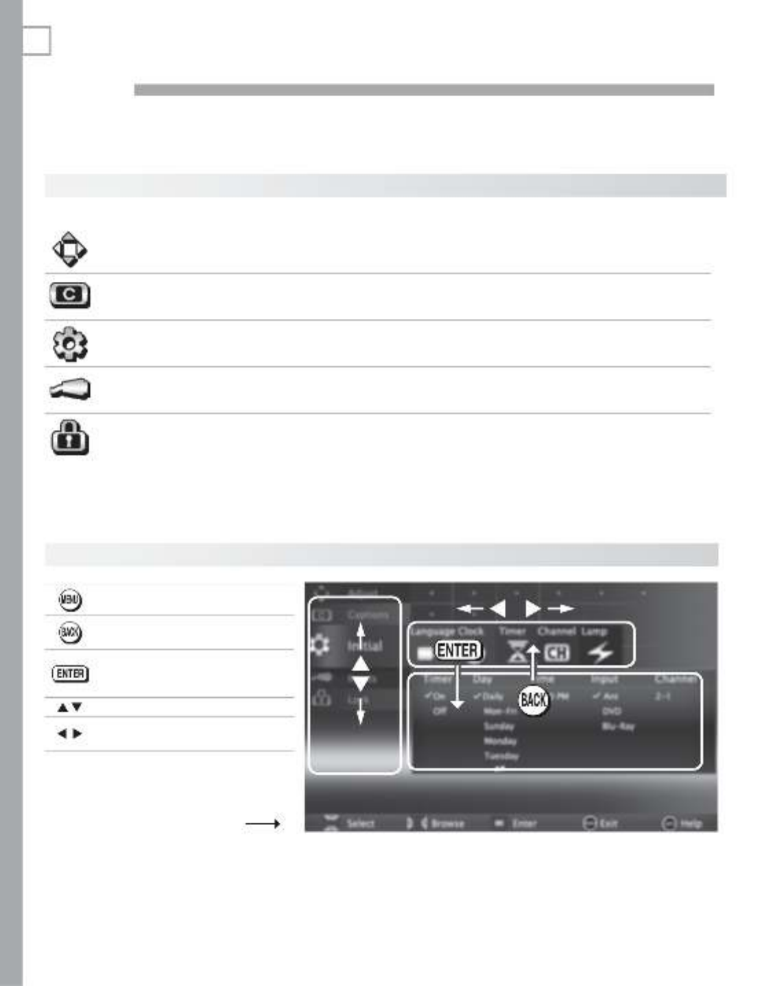
32
4TV Menus
Displays or clears the main menu.
Moves up one menu level.•
Clears the current menu.•
Moves navigation into options •
area.
Selects an item.•
Moves the highlight within menus.
Makes adjustments in some
menus.
Look for the key guide at
the bottom of each menu.
Main Menu
Press
MENU
on the remote control to open the main menu and then select from one of these categories.
Adjust Customize picture and sound settings. 33
Captions Turn closed captions on and off; customize caption displays. 37
Initial Perform basic TV setup. Set language, scan (memorize) channels and edit
channel options, set the TV clock, set Lamp Energy, set auto-on TV Timer. 38
Input Assign names to TV inputs, enable HDMI Control, assign activities to inputs.
837 Series. Perform NetCommand IR “learning.” 40
Lock Restrict TV use. Disable the control-panel buttons. Set a pass code. 42
Menu Navigation

4. TV Menus 33
Picture
See page 35 for picture adjustments.
Audio See page 36 for audio adjustments.
Reset Resets audio and picture adjustments for the current input. Highlight the • Reset icon and press
ENTER
twice
.
Reset• has no effect on global settings (Balance, Listen To Film Mode , Language, , and
Advanced Picture).
Global Video Mute
(non-antenna
inputs only)
On Displays a solid colored background when there is no video signal
from the current input. The colored screen reminds you that the
TV is powered on when there is no picture. The TV will power off
after five minutes without receiving a video signal.
Off The screen appears black when there is no video signal from the
current input.
Audio
Screensaver
On, Off Select On to display a random pattern while playing an audio-only
input. To use this feature, the input must be either
Named as an audio source (e.g., • CD or ) and MP3 Player
selected under the activity.Listen Music
or
Be the •
ANT
input.
Film Mode
(480i and 1080i
signals only)
Auto, Off
In
Auto
, the TV automatically detects and applies film-decoding cor-
rection to movies filmed at 24 frames per second. Try the
Off
setting
if images show many jagged edges.
Smooth 120Hz Off, On
When
On
, Smooth 120Hz™ reduces motion blur in action scenes but
may show pixel structure during slower motion or in still images.
Blue Glow
(837 series)
On, Off Select On to see blue accent lighting when the TV is powered on.
Test Picture
Displays a test picture for use by TV servicers.
Adjust

34 4. TV Menus
Adjust, continued
Picture+
PerfectColor
PerfectColor Sliders
Adjusts the saturation (intensity) of six colors for
the current image source.
PerfectTint Sliders
(837 series)
Adjusts six hues for the current image source
Using PerfectColor:
Highlight the PerfectColor™ icon and press
ENTER
to display the PerfectColor menu. Settings are
retained independently for each TV input.
Using PerfecTint (837 Series):
• ToswitchbetweenPerfectColor™andPerfecTint™adjustments,highlightAdjust Mode and
press
.
• Press to move from one color bar to the next.
• Press to change settings.
• Press
CANCEL
to restore default settings.
• Press
MENU
to return to the main menu.
Advanced
Picture
Advanced Picture allows you to save highly customized picture
adjustments for each input. Mitsubishi recommends a profes-
sional installer make these adjustments.
Press 1.
MENU
. Under Picture+, highlight the icon and press Advanced Picture
ENTER
.
With 2. Picture Mode highlighted, press
ENTER
to change
from blank (undefined)
to
ADV
.
837 Series: Choose
ADV1
(daytime settings) or
ADV2 (nighttime settings)
Use 3.
to
highlight an option you wish to change and press
ENTER
to see the adjustment display.
Press 4.
to change settings.
Use 5.
to
navigate to additional options and press
to change settings
.
Press 6.
MENU
to return to the menuAdvanced Picture
.
Press
MENU
to close the menu
. The
Advanced Picture adjustments will be in effect for the current input.
To use the custom Picture Mode at a later time
Press
MENU
and go to Adjust > Picture > Picture Mode and:
737 and C9 Series 837 Series
Select •
SPECIAL if settings were saved by
your professional installer.
Otherwise select • ADV.
Sele•
ct or t if settings were ISF Day ISF Nigh
saved by your professional installer.
Otherwise select • ADV1 or .ADV2
To return to the default values for Advanced Picture
Display the menu and:Picture+ > Advanced Picture
737 and C9 Series 837 Series
Highlight and press RESET Pic Mode
ENTER
.
Highlight the 1. Advanced Picture mode to change.
H2. ighlight RESET Pic Mode and press
ENTER
.
Repeat this separately for both and .ADV1 ADV2
3D Mode
3D Mode
On, Off
Use the
On
setting for video games and movies that require 3-D
glasses. This setting applies only to the current input.
Note: 3D options are available only for 1080p 60-Hz video
sources connected to an HDMI input.
Glasses L-R Standard,
Reverse
Synchronizes the 3D glasses with the image on screen to provide
the best 3D effect. Try
Reverse
if
Standard
seems incorrect.
Termékspecifikációk
| Márka: | Mitsubishi |
| Kategória: | televízió |
| Modell: | WD-73837 |
Szüksége van segítségre?
Ha segítségre van szüksége Mitsubishi WD-73837, tegyen fel kérdést alább, és más felhasználók válaszolnak Önnek
Útmutatók televízió Mitsubishi

14 December 2024
14 December 2024
14 Október 2024
29 Szeptember 2024
22 Szeptember 2024
17 Szeptember 2024
11 Szeptember 2024
25 Augusztus 2024
21 Augusztus 2024
18 Augusztus 2024
Útmutatók televízió
- televízió Samsung
- televízió Sony
- televízió Yamaha
- televízió Beko
- televízió Fujitsu
- televízió Acer
- televízió Nedis
- televízió LG
- televízió Grundig
- televízió Marantz
- televízió Philips
- televízió Pioneer
- televízió SilverCrest
- televízió Panasonic
- televízió JVC
- televízió AEG
- televízió Sharp
- televízió Nokia
- televízió Lenovo
- televízió Casio
- televízió Toshiba
- televízió Oppo
- televízió Hyundai
- televízió Hisense
- televízió BenQ
- televízió SunBriteTV
- televízió Siemens
- televízió Medion
- televízió TCL
- televízió Xiaomi
- televízió GoGen
- televízió Insignia
- televízió Infiniton
- televízió Dell
- televízió Strong
- televízió VOX
- televízió Vivax
- televízió Thomson
- televízió Polaroid
- televízió Aiwa
- televízió Orima
- televízió V7
- televízió Clatronic
- televízió PEAQ
- televízió Qilive
- televízió Haier
- televízió Cecotec
- televízió Sencor
- televízió GPX
- televízió Küppersbusch
- televízió Innoliving
- televízió AOC
- televízió Citizen
- televízió Westinghouse
- televízió Hitachi
- televízió Continental Edison
- televízió Telefunken
- televízió Nevir
- televízió Monster
- televízió Roadstar
- televízió Optoma
- televízió CHiQ
- televízió Viewsonic
- televízió Nextbase
- televízió Denver
- televízió Bush
- televízió Trevi
- televízió Albrecht
- televízió Daewoo
- televízió Funai
- televízió Tesla
- televízió Smart Tech
- televízió Muse
- televízió Energy Sistem
- televízió OK
- televízió SVAN
- televízió Loewe
- televízió RevolutionHD
- televízió Polar
- televízió Manhattan
- televízió Kogan
- televízió Horizon
- televízió Intenso
- televízió Furrion
- televízió Teac
- televízió Aspes
- televízió Digihome
- televízió Manta
- televízió Blaupunkt
- televízió Sagem
- televízió Jay-Tech
- televízió Logik
- televízió Finlux
- televízió Peerless-AV
- televízió Abus
- televízió AG Neovo
- televízió Bang & Olufsen
- televízió Iiyama
- televízió AKAI
- televízió TechniSat
- televízió Seiki
- televízió Jensen
- televízió Pyle
- televízió Emerson
- televízió Sanyo
- televízió Kemo
- televízió Salora
- televízió Lenco
- televízió Schneider
- televízió Philco
- televízió ECG
- televízió Uniden
- televízió Technika
- televízió NEC
- televízió Element
- televízió Soundmaster
- televízió Alphatronics
- televízió AYA
- televízió MBM
- televízió Krüger&Matz
- televízió Dual
- televízió Brandt
- televízió Wharfedale
- televízió Allview
- televízió RCA
- televízió OKI
- televízió Orion
- televízió SereneLife
- televízió Schaub Lorenz
- televízió Luxor
- televízió Metz
- televízió ILive
- televízió Graetz
- televízió Tatung
- televízió Packard Bell
- televízió EasyMaxx
- televízió Orava
- televízió Arçelik
- televízió Planar
- televízió Zenith
- televízió Doffler
- televízió QBell Technology
- televízió SYLVOX
- televízió Majestic
- televízió Reflexion
- televízió FFalcon
- televízió Megasat
- televízió Sogo
- televízió United
- televízió Techwood
- televízió Newstar
- televízió Matsui
- televízió Alden
- televízió Aldi
- televízió Airis
- televízió Aristona
- televízió Apex
- televízió Icy Box
- televízió Lexibook
- televízió Palsonic
- televízió Walker
- televízió Saba
- televízió Antarion
- televízió Kernau
- televízió Tevion
- televízió Proscan
- televízió Vestel
- televízió Tucson
- televízió Sunstech
- televízió Nabo
- televízió Sylvania
- televízió Sunny
- televízió Marquant
- televízió Nordmende
- televízió AudioAffairs
- televízió Magnum
- televízió Audiosonic
- televízió Kubo
- televízió Proline
- televízió Coby
- televízió Seg
- televízió Vivo
- televízió Daitsu
- televízió Terris
- televízió Changhong
- televízió Alba
- televízió Naxa
- televízió Star-Light
- televízió Fantec
- televízió Mpman
- televízió Sweex
- televízió Vizio
- televízió Cello
- televízió Mx Onda
- televízió Nikkei
- televízió Hannspree
- televízió DGM
- televízió Yasin
- televízió Humax
- televízió XD Enjoy
- televízió MT Logic
- televízió Superior
- televízió Kunft
- televízió Difrnce
- televízió ITT
- televízió Grunkel
- televízió Avtex
- televízió Inovia
- televízió Odys
- televízió NPG
- televízió Bluesky
- televízió Videocon
- televízió Xoro
- televízió Durabase
- televízió HKC
- televízió Edenwood
- televízió Woxter
- televízió Premier
- televízió Onn
- televízió Teleco
- televízió Opera
- televízió LTC
- televízió JTC
- televízió Zalman
- televízió Ferguson
- televízió Viewpia
- televízió XS4ALL
- televízió JGC
- televízió Online
- televízió Dyon
- televízió DirecTV
- televízió Tele 2
- televízió Telesystem
- televízió EKO
- televízió E-motion
- televízió Mitsai
- televízió Selfsat
- televízió High One
- televízió Tve
- televízió ISymphony
- televízió Pantel
- televízió Magnavox
- televízió ATYME
- televízió HCI
- televízió Inno-Hit
- televízió Lin
- televízió Engel
- televízió Bang Olufsen
- televízió TechLine
- televízió Elements
- televízió Englaon
- televízió Time
- televízió Reflex
- televízió Astar
- televízió Visco
- televízió Tivax
- televízió H&B
- televízió Norcent
- televízió TELE System
- televízió TIM
- televízió Oyster
- televízió Belson
- televízió Vision Plus
- televízió Sbr
- televízió Bauhn
- televízió Voxx
- televízió Rm 2000
- televízió Hoher
- televízió Felson
- televízió Mach Power
- televízió Elbe
- televízió Axing
- televízió CGV
- televízió Séura
- televízió Mitzu
- televízió Caratec
- televízió JTC24
- televízió Coocaa
- televízió Kivi
- televízió Smart Brand
- televízió Voxicon
- televízió Aconatic
- televízió Mitchell & Brown
- televízió FOX Electronics
- televízió Mystery
Legújabb útmutatók televízió

10 Április 2025

10 Április 2025

10 Április 2025

9 Április 2025
9 Április 2025
9 Április 2025
9 Április 2025

9 Április 2025
9 Április 2025
9 Április 2025