Használati útmutató Mitsubishi L75-A91 Laservue
Mitsubishi
3D TV
L75-A91 Laservue
Olvassa el alább 📖 a magyar nyelvű használati útmutatót Mitsubishi L75-A91 Laservue (100 oldal) a 3D TV kategóriában. Ezt az útmutatót 11 ember találta hasznosnak és 2 felhasználó értékelte átlagosan 4.5 csillagra
Oldal 1/100

MODEL
L75–A81
MODEL
L75–A91
®
Owner’s Guide

In the U.S. call 1(877) 675-2224 for assistance.
FCC Declaration of Conformity
Product: Projection Television Receiver
Models: L75-A81, L75-A91
Responsible
Party:
Mitsubishi Digital Electronics
America, Inc.
9351 Jeronimo Road
Irvine, CA 92618-1904
Telephone: (800) 332-2119
This device complies with Part 15 of the FCC Rules.
Operation is subject to the following two conditions:
(1)
This device may not cause harmful interference,
and
(2) This device must accept any interference
received, including interference that may cause
undesired operation.
Note: This equipment has been tested and found
to comply with the limits for a Class B digital device,
pursuant to part 15 of the FCC Rules. These limits
are designed to provide reasonable protection
against harmful interference in a residential instal-
lation. This equipment generates, uses and can
radiate radio frequency energy and, if not installed
and used in accordance with the instructions, may
cause harmful interference to radio communica-
tions. However, there is no guarantee that interfer-
ence will not occur in a particular installation. If this
equipment does cause harmful interference to radio
or television reception, which can be determined
by turning the equipment off and on, the user is
encouraged to try to correct the interference by one
or more of the following measures:
Reorient or relocate the receiving antenna. -
Increase the separation between the equip- -
ment and the receiver.
Connect the equipment into an outlet on -
a circuit different from that to which the
receiver is connected.
Consult the dealer or an experienced radio/ -
TV technician for help.
Changes or modifications not expressly
approved by Mitsubishi could cause harmful
interference and would void the user’s authority
to operate this equipment.
Canadian Notice
For Model L75-A81
This Class B digital apparatus complies with
Canadian ICES-003.
CAUTION
RISK OF ELECTRIC SHOCK
DO NOT OPEN
CAUTION: TO REDUCE THE RISK OF ELECTRIC
SHOCK, DO NOT REMOVE COVER (OR BACK).
NO USER SERVICEABLE PARTS INSIDE. REFER
SERVICING TO QUALIFIED SERVICE PERSONNEL.
WARNING: To reduce the risk of fire or electric shock,
do not expose this apparatus to rain or moisture.
This apparatus shall not be exposed to dripping or
splashing and no objects filled with liquids, such as
vases, shall be placed on the apparatus.
Cet appareil ne doit pas être exposé à des gouttes ou
à des éclaboussures et aucun objet rempli d’un liquide,
comme un vase, ne doit être placé sur l’appareil.
WARNING: This product contains chemicals known
to the State of California to cause cancer and/or birth
defects or other reproductive harm.
TV WEIGHT: This TV is heavy. Exercise extreme care
when lifting or moving it. Lift or move the TV with a
minimum of two adults. To prevent damage to the TV,
avoid jarring or moving it while it is turned on. Always
power off your TV, unplug the power cord, and discon-
nect all cables before moving it.
Stand Requirement
Mitsubishi does not design, manufacture or sell match-
ing bases for L75-A81 and L75-A91 model televisions.
When selecting a stand, base, or other furniture to
support the TV, please make sure it is designed with the
appropriate dimensions for stability and to support the
TV’s weight plus the weight of any additional equipment
you plan to store.
Children and Television Viewing
The American Academy of Pediatrics discourages
television viewing for children younger than two years of
age.
MAINS DISCONNECTION: The mains plug is used
as the disconnect device. The mains plug shall remain
readily operable.
The lightning flash with arrowhead symbol
within an equilateral triangle is intended to
alert the user of the presence of uninsulated
“dangerous voltage” within the product’s
enclosure that may be of sufficient magnitude to consti-
tute a risk of electric shock to persons.
The exclamation point within an equilat-
eral triangle is intended to alert the user to
the presence of important operating and
maintenance (servicing) instructions in the
literature accompanying the product.
Note: Features and specifications described in this
owner’s guide are subject to change without notice.

3
In the U.S. call 1(877) 675-2224 for assistance.
Laser Safety
Laser Safety
This TV is in compliance with the requirements of IEC •
60825-1 Ed. 2(2007).
This TV is a CLASS 1 laser product. This TV poses •
no risk to eyes or skin during normal use. An expo-
sure hazard may exist only if the protective housing
is removed.
This TV contains a CLASS 4 laser device, which by •
itself may be hazardous. However, this TV incorpo-
rates a protective housing, optics and electronics
such that there should be no exposure to unsafe
levels of laser light during normal operation and
proper service.
Do not open this product. No consumer controls •
inside. Only a trained LASERVUE® technician
should service this TV. Please call Mitsubishi for
assistance.
In the U.S.A. call 1-877-675-2224. -
In Canada call 1-800-450-6487. -
Safe Operation
Always inspect the TV for damage after moving it. •
If the cabinet or screen is physically damaged, DO
NOT connect the TV to an AC outlet.
In the U.S.A. call 1-877-675-2224 for assistance. -
In Canada call 1-800-450-6487. -
DO NOT power on the TV until it has been repaired
by qualified service personnel authorized by
Mitsubishi. See “Service” on the next page.
Caution.• Use of controls or adjustments or per-
formance of procedures other than those specified
herein may result in hazardous radiation exposure.
Use external or remote controls to operate the •
product. Connection to signal sources and power
are accomplished through the external connectors.
Damage and Repair
There are no user serviceable components in this •
TV. Do not attempt to disassemble any part of the
TV.
If damaged, the device must not be powered on or •
used until it is repaired by qualified service person-
nel authorized by Mitsubishi. See “Service” on the
next page.
Under no circumstances shall attempts be made to •
operate this device without the screen in place or if
any portion of the enclosure, including the screen,
is cracked, broken, a liquid is spilled onto the TV or
is otherwise damaged.
CAUTION
CLASS 4 LASER LIGHT WHEN
OPEN AVOID EYE OR SKIN
EXPOSURE TO DIRECT OR
SCATTERED RADIAITON
ATTENTION
LUMIÈRE LASER DE CLASSE 4 - EN CAS
D’OUVERTURE EXPOSITION DANGERE-
USE AU RAYONNEMENT DIRECT OU
DIFFUS DES YEUX OU DE LA PEAU
This class-4 label and similar service warning labels
are located inside the back cover of the television in an
area that should not be accessed by the user under any
circumstances.
An additional class-4 label is located at the lower front
access panel under the front decorative bezel.
This class-4 label is located at the center back of the TV
under the outer cover.
This label is located on the right lower back of the
television set.

In the U.S. call 1(877) 675-2224 for assistance.
Contents
Important Information About Your TV
Important Safety Instructions ................ 2
Laser Safety ........................... 3
Installation and Operating Notes ............. 4
1 Basic Setup and Operation
Package Contents ....................... 6
Special Features of Your TV................. 7
TV Controls and Indicators ................. 8
First-Time Power-On ..................... 11
Setting Up TV Inputs..................... 12
Basic TV Operation...................... 14
Using the TV with a Personal Computer ....... 16
2 TV Connections
Before You Begin ....................... 18
Cable Management ..................... 18
Inputs and Outputs ...................... 19
Y Pb Pr Component Video Device ........... 21
H
DMI Device .............................21
DVI Video Device ....................... 22
Antenna or Cable TV Service ............... 22
Composite Video Device .................. 22
VCR or DVD Recorder to an Antenna or
Wall Outlet Cable ...................... 23
VCR or DVD Recorder to a Cable Box ........ 23
A/V Receiver .......................... 24
A/V Receiver with HDMI Output ............. 24
3 Using TV Features
Selecting an Input ...................... 25
Sleep Timer ........................... 25
ChannelView Channel Listings .............. 26
Redirecting Audio Output ................. 26
Controlling A/V Receiver Sound Volume ....... 26
Status Display ......................... 27
TV Signals and Display Formats ............. 28
3D Video ............................. 29
Camera and Music Files .................. 31
Streaming Internet Movies with VUDU ........ 34
Introduction to Home-Theater Control ........ 36
4 TV Menus
Main Menu ............................ 37
Menu Navigation ....................... 37
Adjust ............................... 38
Captions ............................. 42
Initial ................................ 43
Inputs ............................... 45
Lock ................................ 47
5 NetCommand IR Control
About NetCommand IR Control ............. 50
IR Emitter Placement .................... 51
Initial NetCommand Setup ................ 52
Operating NetCommand-Controlled Devices ... 53
6 NetCommand IR Control of an A/V Receiver
Controlling an A/V Receiver after
NetCommand Setup .................... 56
Setting Up A/V Receiver Control
Power and Volume ................... 57
Automatic Audio or Audio/Video Switching . . 58
Appendices
Appendix A: Programming the Remote Control . 64
Appendix B: Bypassing the Parental Lock ..... 71
Appendix C: HDMI Control of CEC Devices .... 73
Appendix D: TV Care .................... 76
Appendix E: Troubleshooting .............. 77
Trademark and License Information .......... 84
Mitsubishi TV Software .................... 85
Warranty .............................. 88
Index ................................. 92
6
In Canada call 1(800) 450-6487 for assistance.
Basic Setup and Operation
1
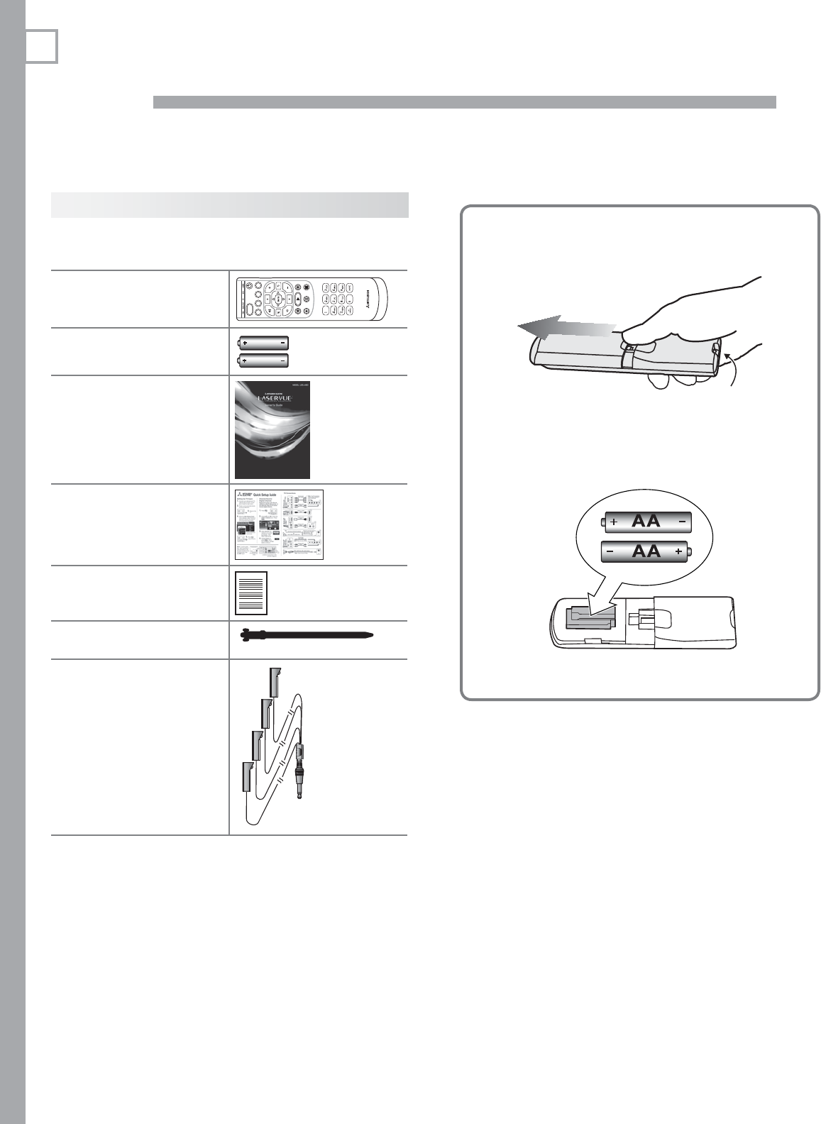
Package Contents
Please take a moment to review the following list of
items to ensure that you have received everything.
Remote Control Batteries
Remove the remote control back cover.1.
Emitter bulb
Load the batteries, making sure the polarities 2.
(+) and (-) are correct. Insert the negative (-)
end first.
Slide the cover back into place.3.
Remote Control1.
GUIDE MENU INFO BACK
ACTIVITY
Two AA Batteries2.
AA
AA
Owner’s Guide3.
Quick Setup Guide4.
Product Registra-5.
tion Card
Cable Tie6.
L75-A91: Four-ended 7.
IR emitter cable
1. Basic Setup and Operation 9
In the U.S. call 1(877) 675-2224 for assistance.
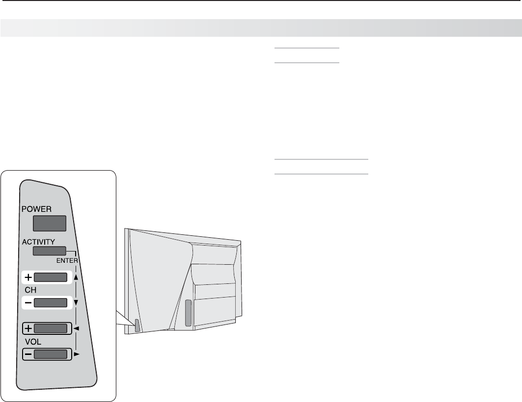
TV Control Panel
Buttons on the control panel duplicate some keys on
the remote control.
Refer to • left labels when no TV menus are dis-
played.
Refer to • right labels when using TV menus or after
activating a special function.
System Reset
If the TV fails to respond to the remote control, the
control-panel buttons, or will not power on/off, perform
System Reset. Recent setting changes made before
using System Reset may be lost.
To perform System Reset, press and hold the
POWER
button on the control panel for ten seconds.
Panel-Lock Release
To • release the Panel Lock using the TV control
panel, press and hold the
ACTIVITY
button on the
control panel for ten seconds. If the TV is off, press
the
POWER
button to make it power on.
To activate the Panel Lock, use the • Lock menu,
page 49.
TV Controls and Indicators, continued

10 1. Basic Setup and Operation
In Canada call 1(800) 450-6487 for assistance.
Key
Off
Steady On
Slow Blinking
Fast Blinking
POWER Indicator
LED Color TV Condition Additional Information
None TV is powered off. Normal operation.
Green TV is powered on. Normal operation.
Green TV powered off, auto-on TV Timer is set. Normal operation. TV can be turned on at any time.
Green TV power just turned on. Normal operation. A picture will appear shortly.
TV just plugged into AC outlet.•
AC just restored after power failure.•
TV is rebooting after power fluctua-•
tion or receiving abnormal digital
signals from a digital channel or
digital device.
You have begun the procedure to •
update software from an authorized
flash memory device.
Wait approximately two minutes for blinking to stop before
turning on. Normal operation.
Yellow TV is too hot.
The TV will display a warning message and shut off if it over-
heats.
• Ambientroomtemperaturemaybetoohigh.Turnoff
the TV and let the room temperature drop.
• Clearblockedairvents.Ensureatleastafour-inch
clearance on all sides of the TV.
Red
TV may require service.
Turn off the TV and unplug the set from the AC power
source. Wait one minute and then plug the set back in. See
Appendix E.
If the LED is still on, contact Mitsubishi to receive Authorized
Service Center information:
U.S.A. Go to www.mitsubishi-tv.com or call 1-877-675-2224.
Canada. Go to www.MitsubishiElectric.ca or call
1-800-450-6487.
POWER
POWER
TV Controls and Indicators, continued

1. Basic Setup and Operation 11
In the U.S. call 1(877) 675-2224 for assistance.
Before You Begin
Review the important safety, installation, and oper-
1.
ating information at the beginning of this book.
Choose a location for your TV.
2.
• Allowatleastfourinchesofspaceonallsides
of the TV to help prevent overheating. Over-
heating may cause premature failure of the TV.
• Avoidlocationswherelightmayreflectoffthe
screen.
• Seethestandrequirementsonpage 1.
Install the batteries in the remote control.
3.
Plug the TV into an AC power outlet.
4.
Power-On
Confirm that the remote
1.
control is in
TV
mode.
Press the side button •
once to light the mode
indicator and confirm
that
TV
mode is active.
To change, press the •
side button additional
times to activate
TV
mode.
GUIDE MENU INFO BACK
TV
Aim the remote control
2.
at the TV and press the
POWER
key . Wait for the
Welcome screen.
GUIDE MENU INFO BACK
Press
3.
if you wish to
change the menu language
to Español.
Press
4.
to move to the
Home/Retail selections.
Here you can choose a
picture mode suited to your
viewing conditions.
Mitsubishi recommends the • Home setting.
The Home setting selects the Brilliant Picture
Mode.
The • Retail setting selects the Super Brilliant
Picture Mode. The Super Brilliant Picture
Mode is designed to compensate for the
harsh, bright lighting used in retail settings and
is not recommended for home use. Prolonged
use of the Super Brilliant Picture Mode will age
the lasers faster, reducing picture brightness
as the TV ages.
For more on Picture Modes, see • page 38.
Press
5.
to highlight EXIT.
Press
ENTER
to clear the
menu.
First-Time Power-On
TV Tips
Turning the TV On or Off
Point the remote control at the front of the TV •
and press the
POWER
button.
Press the •
POWER
button on the TV control
panel.
Controlling Sound Volume
Press •
VOLUME
UP/VOLUME DN
to adjust the sound
level from the TV speakers.
See also • “Controlling A/V Receiver Sound
Volume” on page 26.
14 1. Basic Setup and Operation
In Canada call 1(800) 450-6487 for assistance.
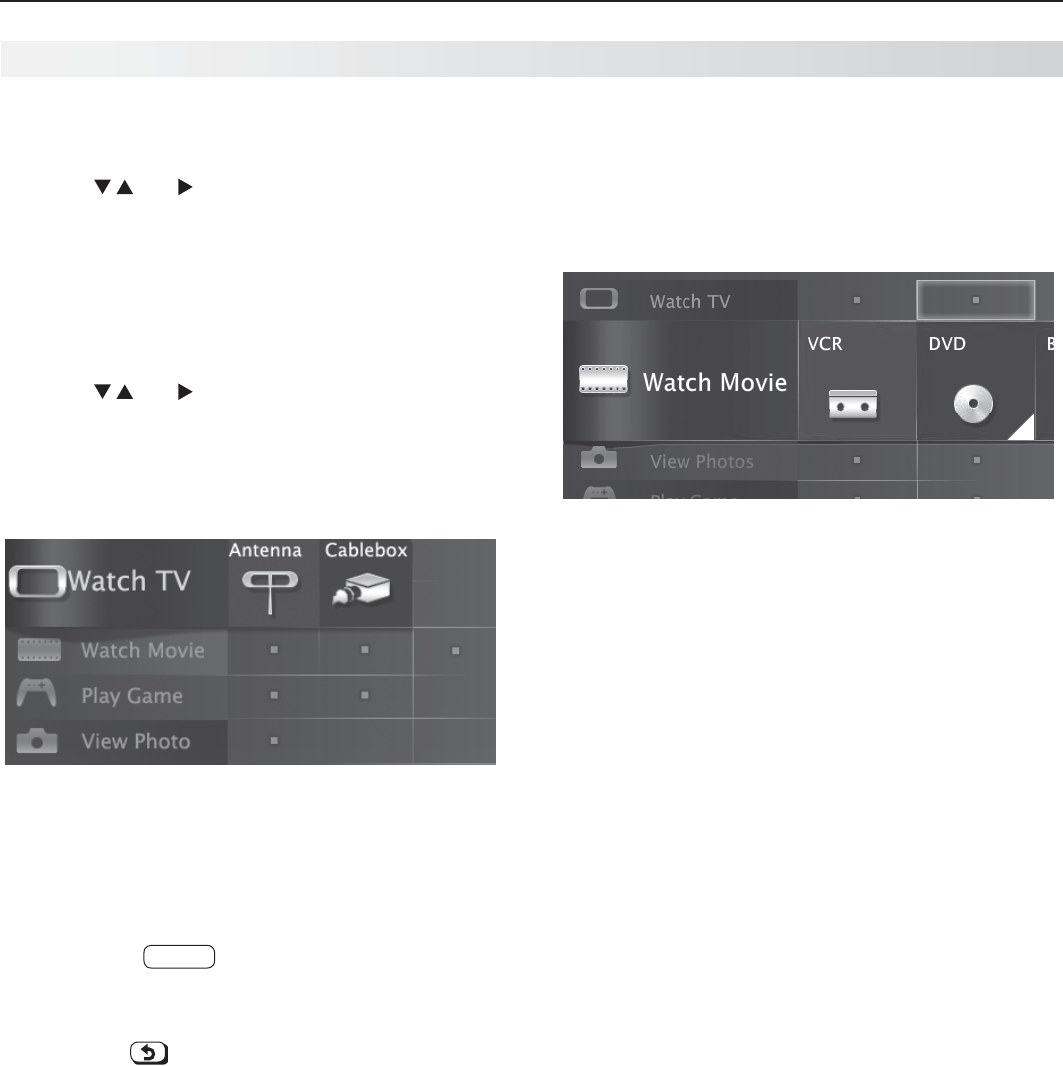
Selecting an Input to Watch
Press
1.
ACTIVITY
.
Press
2.
and to highlight an input.
Press
3.
ENTER
to switch to the input.
Watching Broadcast TV
TV Connected to an Antenna, Direct Cable, Cable
Box, Set-Top Box, or Satellite Receiver
Press
1.
ACTIVITY
.
Press
2.
and to select a broadcast source. If
you named devices during Auto Input Sensing,
select an input from the Watch TV group. Note:
Your TV may have only one group (Watch TV).
Note: For more about the Activity menu, see page 25.
Activity menu, antenna input selected
Tune to a channel on the
3. ANT
input using any of
these methods.
Enter the channel number using the number •
keys on the remote control and press
ENTER
.
For a two-part digital channel, such as 3-1,
press
3
—
CANCEL
1
to enter a dash (separator).
Press •
CHANNEL UP /CHANNEL DN
(
+
/
–
) to change
channels one channel at a time.
Press •
(LAST)
to switch back to the previ-
ously tuned channel.
Antenna or Direct Cable Only.• Press
GUIDE
to
display ChannelView channel listings, highlight
a channel number, and press
ENTER
to tune.
Note: Program information is provided by
broadcasters and may not be available in all
areas.
Watching DVDs or Videos
TV Connected to a DVD Player, DVR, or VCR
Press
ACTIVITY
and select a movie source from the
Activity menu. If you named devices during Auto Input
Sensing, select the input from the Watch Movie group.
Activity menu, DVD input selected
Basic TV Operation

1. Basic Setup and Operation 15
In the U.S. call 1(877) 675-2224 for assistance.
Making Picture Adjustments
To get the best picture under different viewing con-
1.
ditions, set the Picture Mode before changing other
video settings. See page 38 for more.
a. Press
MORE.
b. Press
8
(VIDEO).
c. Press to make one of these Picture Mode
selections:
Name When to Use
Super
Brilliant
Under harsh retail lighting; not
recommended for home use
Brilliant
Under bright light
Game
With gaming consoles
Bright For most daytime viewing
Natural For most nighttime viewing
Cinema For recreating theater colors
Press
2.
to display the name of the next adjust-
ment you want.
Press
3.
to make the adjustment.
Additional picture adjustments are described on pages
40 and 41.
Audio Settings
Changing the Audio Output
To switch audio output from the internal TV speakers to
a connected external sound system or headphones:
Press
1.
MORE
.
Press
2.
9
(AUDIO).
Press
3.
until the Speakers option is displayed.
The Speakers option will display only if a connec-
tion has been detected on one of the TV’s audio
outputs.
Press
4.
to switch between TV and either AV
Receiver or Headphones.
Changing Audio Settings
Press
1.
MORE
.
Press
2.
9
(AUDIO).
Press
3.
to display the name of the adjustment
you want.
Press
4.
to change the setting.
Other TV Features
Activate Audio Lock to control your sound system •
with the TV’s remote control left in
TV
mode. See
page 65.
To set the TV Clock see • page 43. Set the TV
Clock if you plan to use the TV Timer (page 43) or
ChannelView (page 26) features.
To set parental controls, see the • Lock menu, page
47.
Note: L75-A91. To set parental controls for
VUDU™ service, use the VUDU Info & Settings
menu.
To change the input names that appear in the •
Activity menu, see Inputs > Name options, page
45.
3D Video.• See page 29.
To program the remote control to operate other •
A/V devices, see Appendix A, “Programming the
Remote Control,” page 64.
To control compatible devices using HDMI CEC •
control, see Appendix C, “HDMI Control of CEC
Devices,” page 73.
To view still and moving digital camera images on •
the TV, see “Camera and Music Files,” page 31.
L75-A91.• To control A/V devices with NetCom-
mand, see chapter 5, “NetCommand IR Control for
Most Devices” on (page 50).
L75-A91.• See page 34 for internet video streaming
with VUDU™.
Basic TV Operation, continued
Other Information
TV Care
Remote Control.• See “Care of the Remote
Control” on page 76
General Cleaning.• See “Cleaning Recommenda-
tions,” page 76.
Assistance
For basic troubleshooting, see • Appendix E, page
77.
For service, and product support, see • page 4.
For warranty information, see the TV warranty on •
page 88.
16 1. Basic Setup and Operation
In Canada call 1(800) 450-6487 for assistance.
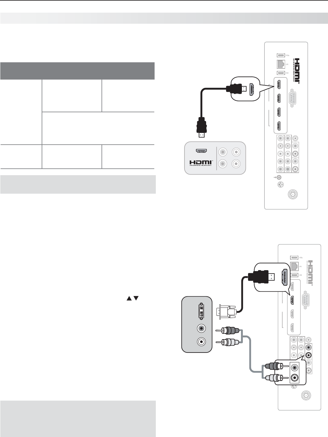
Connecting a Computer to the TV
Use one of the connection methods listed below based
on your computer’s video output.
Computer
Video Output
Video Connection Audio
Connection
Digital DVI DVI-to-HDMI cable
or an HDMI cable
with an HDMI-to-
DVI adapter
Stereo audio
cables
Note: If the computer’s audio output
is a single mini jack, a mini audio-to-
RCA-male “Y” adapter cable is also
required.
HDMI HDMI-to-HDMI
cable
No additional
audio connec-
tion is required.
IMPORTANT
This TV accepts digital computer signals only.
Connect the computer’s digital signal output to one
1.
of the TV’s
HDMI
jacks. See the connection dia-
grams for the method suited to your equipment.
Connect the computer’s audio output using one of
2.
these options:
• FordigitalDVIsignals,connectanalogleft/right
audio to the TV’s
DVI/PC INPUT AUDIO
jacks.
• ForHDMIsignals,noadditionalaudioconnec-
tion is required.
Power on the TV and computer. The TV will detect
3.
the connection and display the New Device Found
screen.
In the
4.
New Device Found screen, press to
highlight PC in the list of device types. It is impor-
tant to use the name PC so that the TV processes
the computer signal correctly.
Press
5.
BACK
to close the New Device Found screen.
1 2 3 4
HDMI
AVR AUDIO OUTPUT
DIGITAL
AUDIO
OUTPUT
RS-232C
3D
GLASSES
EMITTER
ANT
INPUT 2
INPUT 1
DVI/PC L
RL
R
INPUT
IR-
NetCommand
Output/External
Controller Input
Pb Pr
LR
Y/ VIDEO
Computer with
HDMI output
TV
panel
An HDMI-to-HDMI connection carries all video and
audio on a single cable.
1 2 3 4
HDMI
AVR AUDIO OUTPUT
DIGITAL
AUDIO
OUTPUT
RS-232C
3D
GLASSES
EMITTER
ANT
INPUT 2
INPUT 1
DVI/PC L
RL
R
INPUT
IR-
NetCommand
Output/External
Controller Input
Pb Pr
LR
Y/ VIDEO
DVI/PC L
RINPUT
DVI/PC L
RINPUT
DVI
OUT
AUDIO
R
L
Computer with
DVI and analog
stereo outputs
TV
A DVI connection from a personal computer requires a
separate audio connection.
Note: If your computer provides digital audio out-
put (coaxial or optical), you can connect it
directly to a digital A/V receiver and bypass
the TV.
Using the TV with a Personal Computer

1. Basic Setup and Operation 17
In the U.S. call 1(877) 675-2224 for assistance.
Tip
Set the computer’s screen saver to display a pattern
after several minutes of inactivity. This acts as a
reminder that the TV is powered on.
Computer Video Adjustments
Power on the computer.
1.
Select
2.
PC from the Activity menu. To do this,
press
ACTIVITY
to open the Activity menu, move the
highlight to the PC icon, and press
ENTER.
Working from the computer, change the resolution
3.
of the computer image. View the computer image
on the TV and maximize the computer resolution
while maintaining a suitable aspect ratio for the
image.
Perform TV video adjustments.
4.
Press
MORE
then press
8
(VIDEO). Use
to cycle through video-adjustment
options.
Press
5.
MORE
then press
0
(FORMAT)
repeatedly to find the picture format
(aspect ratio) best suited to the image.
See the chart on this page showing
how different computer resolutions
can be displayed on the TV.
Image Resolution
Your Mitsubishi TV can display the resolu-
tions shown in the chart from standard
VGA (640 x 480) through 1920 x 1080
signals at a refresh rate of 60 Hz.
In most cases, the computer will select
the best resolution match to display on
the TV. You can override this setting if you
wish. Refer to your computer operating
system’s instructions for information on
changing the screen resolution.
You may need to restart the computer for
changes to take effect.
Using the TV with a Personal Computer, continued
Distortion in Computer Images
Computer images may show distortion
when viewed on the TV, e.g., lines that
should be straight may appear slightly
curved.
Computer Display Formats
Press
MORE
then press
0
(FORMAT) repeatedly to cycle through the
TV displays available for your computer’s video signal.
Computer Signal
As Displayed on TV Screen
Original Format 4 X 3
Standard
16 X 9
Standard Zoom
VGA
640 X 480
SVGA
800 X 600
Original Format Standard Zoom
XGA
1024 X 768
PC 720p
1280 X 720
WXGA
1360 X 768
SXGA
1280 X 1024
Original Format Standard Reduce
PC 1080p
1920 X 1080
18
In Canada call 1(800) 450-6487 for assistance.
2TV Connections
Auto Input Sensing
The TV’s Auto Input Sensing feature automatically rec-
ognizes most connections and prompts you to identify
the type of device connected. See page 13 for more on
Auto Input Sensing.
Connection Types
Use the connection types available on your input
devices that will give the best video quality. For
example, choose HDMI over component video, and
choose component video over composite video.
Picture Quality
For best picture quality, route signals directly from the
input device to the TV whenever possible.
Surround Sound
For best surround sound audio quality, route audio-
signal cables or HDMI cables from the source device
directly to your A/V receiver or sound system.
IMPORTANT
Accessory items such as cables, adapters,
splitters, or combiners required for TV
connections are not supplied with the TV.
These items are available at most electronics
stores.
Before You Begin
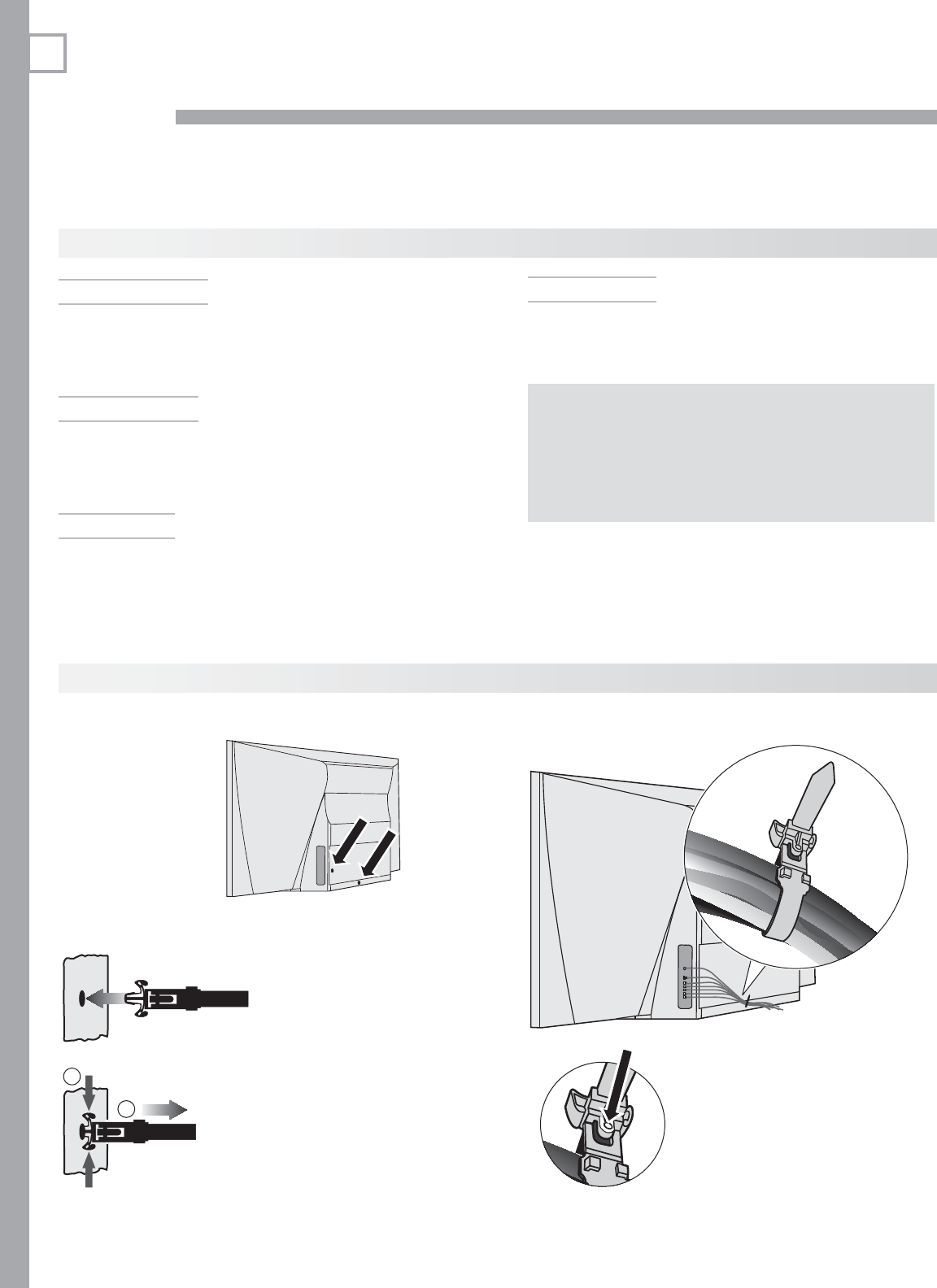
Cable Management
1
2
Install the cable tie
(supplied) in one of
the mounting holes
on the back.
Lock the cable tie in place
by pushing the end into
the mounting hole.
To remove the cable tie,
squeeze the side tabs and
pull out.
Sample cable routing. Secure
the cable bundle with the
release tab facing out.
Press the release tab to
loosen the cable tie.

2. TV Connections 19
In the U.S. call 1(877) 675-2224 for assistance.
1 2 3 4
HDMI
AVR AUDIO OUTPUT
DIGITAL
AUDIO
OUTPUT
RS-232C
3D
GLASSES
EMITTER
ANT
INPUT 2
INPUT 1
DVI/PC L
RL
R
INPUT
IR-
NetCommand
Output/External
Controller Input
Pb Pr
LR
Y/ VIDEO
1
2
13
14
8
10
4
12
3
11
9
5
6
7
Inputs and Outputs
HDMI
(page 21)
LAN
(page 34)
USBa
(power
only, page 34)
RS-232
AVR AUDIO
OUTPUT
(page 24)
DVI/PC INPUT
(audio input,
page 22)
DIGITAL AUDIO
OUTPUT
(page 24)
VIDEO
(composite video,
page 23)
Y Pb Pr
(component video,
page 21)
ANT
(page 22)
IR
–
NetCommand
Output/External Con-
troller Input
(page 51)
3D GLASSES EMITTER
(page 29)
USB
(page 31)
IR-NetCommand
Output/External
Controller offered
on L75-A91.
RS-232 control
jack is offered on
L75-A91.
HDMI 4 offered
on L75-A91.
1. ANT (Antenna)
Connect your main antenna or direct cable service
(no cable box) to
ANT
. The
ANT
input can receive
digital and analog over-the-air channels from a
VHF/UHF antenna or non-scrambled digital/analog
cable source.
2. 3D GLASSES EMITTER
Use this jack for the special IR emitter supplied
with 3D glasses. The emitter will send a signal that
synchronizes your 3D glasses with the screen display.
See page 29
3. IR–NetCommand Output/External
Controller Input
Connect IR emitters to this jack to send control
signals to external IR-controlled devices. This jack
can also serve as the input for an external controller.
4. Y Pb Pr (Component Video)
Connect devices with component video outputs to
this jack. Use the adjacent
INPUT 1/INPUT 2
audio
R
and
L
jacks if you wish to send audio to the TV.
5.
VIDEO
(Composite Video)
Connect a VCR, DVD player, standard satellite
receiver, or other A/V device to the TV. Use the
adjacent
INPUT 1/INPUT 2
audio
R
and
L
jacks if you
wish to send audio to the TV.
6. L/R (Left/Right Analog Stereo Inputs)
Use with
INPUT 1/INPUT 2
video inputs, items
4 and 5.
USBa and LAN jacks
offered on L75-A91.

20 2. TV Connections
In Canada call 1(800) 450-6487 for assistance.
Inputs and Outputs, continued
7. HDMI™ Inputs
(High-Definition
Multimedia Interface)
The HDMI inputs support uncompressed standard and
high-definition digital video formats and PCM digital
stereo audio.
Mitsubishi recommends you use category 2 HDMI
cables, also called high-speed HDMI cables, to
connect HDMI 1.3 source devices. High-speed cat-
egory 2 cables bring you the full benefits of Deep Color
and x.v.Color.
These HDMI inputs can also accept digital DVI video
signals. To connect a device’s DVI output to the TV’s
HDMI input, use an HDMI-to-DVI adapter or cable plus
analog audio cables. Connect the analog audio cables to
the
DVI/PC INPUT AUDIO
jacks on the TV to receive left
and right stereo audio from your DVI device.
Use the HDMI inputs to connect to CEA-861 HDMI com-
pliant devices such as a high-definition receiver or DVD
player. These inputs support 480i, 480p, 720p, 1080i,
and 1080p video formats.
The TV’s HDMI inputs are compatible with many DVI-D
and HDMI computer signals.
These inputs are HDCP (High-Bandwidth Digital Copy
Protection) compliant.
8. DIGITAL AUDIO OUTPUT
This output sends Dolby Digital or PCM digital audio
to your digital A/V surround sound receiver. Incoming
analog audio is converted by the TV to PCM digital audio.
If you have a digital A/V receiver, in most cases this is the
only audio connection needed between the TV and your
A/V receiver.
HDMI Cable Categories
HDMI cables are available as Standard and
High-Speed types.
High-Speed HDMI Cables • (also called Category 2
Cables). Newer DVD players, video games, and set-top
boxes require High-Speed HDMI cables, suitable for
clock frequencies up to 340 MHz or data rates of up to
10.2 gigabits per second. Use high-speed cables for
1080p HD signals carrying extended color encodings
(i.e., 30 or more bits, also called Deep Color). High-
Speed HDMI cables are also suitable for standard HDTV
signals.
Standard HDMI Cables• (also called Category 1 Cables).
Standard HDMI cables may be unmarked. They are suit-
able for standard HDTV 720p, 1080i, and 1080p signals
with 8-bit color depth. Use category 1 cables for clock
frequencies up to 74.25 MHz or data rates of up to 2.23
gigabits per second.
9. DVI/PC INPUT AUDIO
When connecting a DVI device to one of the TV’s HDMI
inputs, use these jacks for left and right analog audio.
10. AVR AUDIO OUTPUT
Use
AVR AUDIO OUTPUT
to send analog audio of the
current program to an analog A/V surround sound
receiver or stereo system. Digital audio from digital
channels and HDMI devices is converted to analog
audio by the TV for output on this jack. This is the only
audio connection needed to the TV if using an analog
A/V receiver or stereo system.
Headphones. These jacks can also be used for head-
phones that accept standard line level audio signals.
An adapter may be required.
11. USB
The TV can read JPEG photo files and mp3 music files
from a USB device connected to the USB port.
12. RS-232C
L75-A91. Use the RS-232C interface to receive control
signals from compatible home-theater control devices.
See www.mitsubishi-tv.com for a list of control signals
for this interface.
13. LAN
L75-A91. Use the
LAN
Ethernet jack for streaming
internet video to the TV. See page 34 for setup. Visit
www.VUDU.com for details about VUDU™ service.
14. USBa
L75-A91. Standard USB 5-volt, 500-milliamp power
output you can use to supply power to an accessory
device. For use with the VUDU wireless adapter, see
page 34.

2. TV Connections 21
In the U.S. call 1(877) 675-2224 for assistance.
H
DMI Device
HDTV Cable Box, Satellite Receiver, DVD/
Blu-ray Player
Required: HDMI-to-HDMI cable.
Connect an HDMI cable from the TV back panel to the
HDMI device output. HDMI devices provide video and
audio through the single cable.
Mitsubishi recommends you use category 2 (high-
speed) HDMI cables to connect HDMI 1.3 source
devices. High-speed category 2 cables bring you the
full benefits of Deep Color and x.v.Color. See “HDMI
Cable Categories” on the opposite page for more on
HDMI cable types.
1 2 3 4
HDMI
AVR AUDIO OUTPUT
DIGITAL
AUDIO
OUTPUT
RS-232C
3D
GLASSES
EMITTER
ANT
INPUT 2
INPUT 1
DVI/PC L
RL
R
INPUT
IR-
NetCommand
Output/External
Controller Input
Pb Pr
LR
Y/ VIDEO
Any device with
HDMI output
TV
panel
IMPORTANT
HDMI and Audio Signals
Digital Surround Sound: The TV’s HDMI inputs
can receive digital stereo audio signals only. To
hear digital surround sound from an HDMI device,
connect the device’s HDMI or digital audio output
directly to your A/V receiver. See the Owner’s
Guides for those devices for instructions.
Y Pb Pr Component Video Device
HDTV Cable Box, Satellite Receiver, DVD/
Blu-ray Player
If your source device has an HDMI output, use the
connections for HDMI devices described on this page
instead of Y Pb Pr component video.
Required:
1. RCA-type component video cables
2. Left/right analog audio cables.
Note:
To hear digital surround sound, connect the digital
audio output from the device directly to your digital
A/V receiver.
PbY Pr
AUDIO
LR
1 2 3 4
HDMI
AVR AUDIO OUTPUT
DIGITAL
AUDIO
OUTPUT
RS-232C
3D
GLASSES
EMITTER
ANT
INPUT 2
INPUT 1
DVI/PC L
RL
R
INPUT
IR-
NetCommand
Output/External
Controller Input
Pb Pr
LR
Y/ VIDEO
Pb Pr
LR
Y/ VIDEO
Pb Pr
LR
Y/ VIDEO
TV
panel
2.
2.
1. 1.
1.
3.
CABLE IN or
SATELLITE IN
Incoming from
cable service or
satellite dish
Any device with com-
ponent video output

22 2. TV Connections
In Canada call 1(800) 450-6487 for assistance.
DVI Video Device
Cable Box, Satellite Receiver, DVD Player
Connect DVI devices (digital only) to the TV’s HDMI
input jacks.
Required:
1. DVI-to-HDMI cable or DVI/HDMI adapter and
HDMI cable
2. Analog stereo audio cables
If you are using a DVI/HDMI adapter, it is important to
connect the adapter to the DVI device for best perfor-
mance.
Some devices require connection to an analog input
first in order to view on-screen menus and to select DVI
as the ouput. Please review your equipment instruc-
tions for DVI connectivity and compatibility.
Note: The HDMI connection supports copy protection
(HDCP).
1 2 3 4
HDMI
AVR AUDIO OUTPUT
DIGITAL
AUDIO
OUTPUT
RS-232C
3D
GLASSES
EMITTER
ANT
INPUT 2
INPUT 1
DVI/PC L
RL
R
INPUT
IR-
NetCommand
Output/External
Controller Input
Pb Pr
LR
Y/ VIDEO
DVI/PC L
RINPUT
DVI/PC L
RINPUT
DVI
OUT
AUDIO
R
L
Digital DVI
device
TV
panel
1.
2.
Antenna or Cable TV Service
Connect the incoming cable to the TV’s
ANT
input.
1 2 3 4
HDMI
AVR AUDIO OUTPUT
DIGITAL
AUDIO
OUTPUT
RS-232C
3D
GLASSES
EMITTER
ANT
INPUT 2
INPUT 1
DVI/PC L
RL
R
INPUT
IR-
NetCommand
Output/External
Controller Input
Pb Pr
LR
Y/ VIDEO
ANT
ANT
IN OUT
Cable TV
service
UHF/VHF
antenna
TV panel
Not recommeded.
Other connection
types provide better
quality audio and
video.
Direct cable (no cable box)
or
or
Older
cable
box
300-ohm-to75-
ohm combiner
(side view)
1 2 3 4
HDMI
AVR AUDIO OUTPUT
DIGITAL
AUDIO
OUTPUT
RS-232C
3D
GLASSES
EMITTER
ANT
INPUT 2
INPUT 1
DVI/PC L
RL
R
INPUT
IR-
NetCommand
Output/External
Controller Input
Pb Pr
LR
Y/ VIDEO
AUDIO OUT
COMPOSITE
VIDEO OUT LR
LR
Y/ VIDEO
LR
Y/ VIDEO
2.
1.
TV panel
Composite
video cable
VCR or other device with
composite video output
Composite Video Device
VCR or other device with composite video
output
Required:
1. Composite video cable (usually yellow)
2. Analog stereo audio cables.

2. TV Connections 23
In the U.S. call 1(877) 675-2224 for assistance.
VCR or DVD Recorder to an
Antenna or Wall Outlet Cable
Required:
1. Video cables
1a. Component video cables (red/blue/green)
or
1b. Composite video cable (usually yellow)
2. Left/right analog audio cables.
3. Two-way RF splitter
4. Two coaxial cables
Note:
Use composite video only if component video or •
HDMI are unavailable. For an HDMI connection
between the TV and recorder, see page 21.
If your recording device has an analog-only tuner, •
you must use a digital converter box to enable
recording of digital broadcasts.
2 3 4
HDMI
AVR AUDIO OUTPUT
DIGITAL
AUDIO
OUTPUT
RS-232C
3D
GLASSES
EMITTER
ANT
INPUT 2
INPUT 1
DVI/PC L
RL
R
INPUT
IR-
NetCommand
Output/External
Controller Input
Pb Pr
LR
Y/ VIDEO
AUDIO OUT
COMPOSITE
VIDEO OUT COMPONENT
VIDEO OUT
LR
LR
Pb Pr
Y/ VIDEO
Y/ VIDEO
Y/ VIDEO
Pb Pr
LR
ANT
ANTENNA
IN
TV
1a.
2.
3. 4.
4.
1b. or
DVD Recorder or VCR
Incoming
cable
RF Splitter
VCR or DVD Recorder to a Cable Box
Required:
1. Video cables
1a. Component video cables (red/blue/green)
or
1b. Composite video cable (usually yellow)
2. Left/right analog audio cables.
3. One coaxial cable
4. Video and audio cables required to connect the TV
to the cable box.
Notes: Use composite video only if component video or
HDMI are unavailable. For an HDMI connection
between the TV and recorder, see page 21.
When using this connection configuration, it is
possible to view live cable programs through the
recording device. For best picture quality always
view live cable programs directly from the TV input
connected to the cable box device.
2 3 4
HDMI
AVR AUDIO OUTPUT
DIGITAL
AUDIO
OUTPUT
RS-232C
3D
GLASSES
EMITTER
ANT
INPUT 2
INPUT 1
DVI/PC L
RL
R
INPUT
IR-
NetCommand
Output/External
Controller Input
Pb Pr
LR
Y/ VIDEO
AUDIO OUT
COMPOSITE
VIDEO OUT COMPONENT
VIDEO OUT
LR
LR
Pb Pr
Y/ VIDEO
Y/ VIDEO
Y/ VIDEO
Pb Pr
LR
ANT
ANTENNA
IN
IN
OUT
TV
1a.
2.
2.
3.
4.
1b. or
DVD Recorder or VCR
Incoming cable
Audio and video
from cable box
directly to TV,
preferably HDMI or
componenet
connections.
24 2. TV Connections
In Canada call 1(800) 450-6487 for assistance.
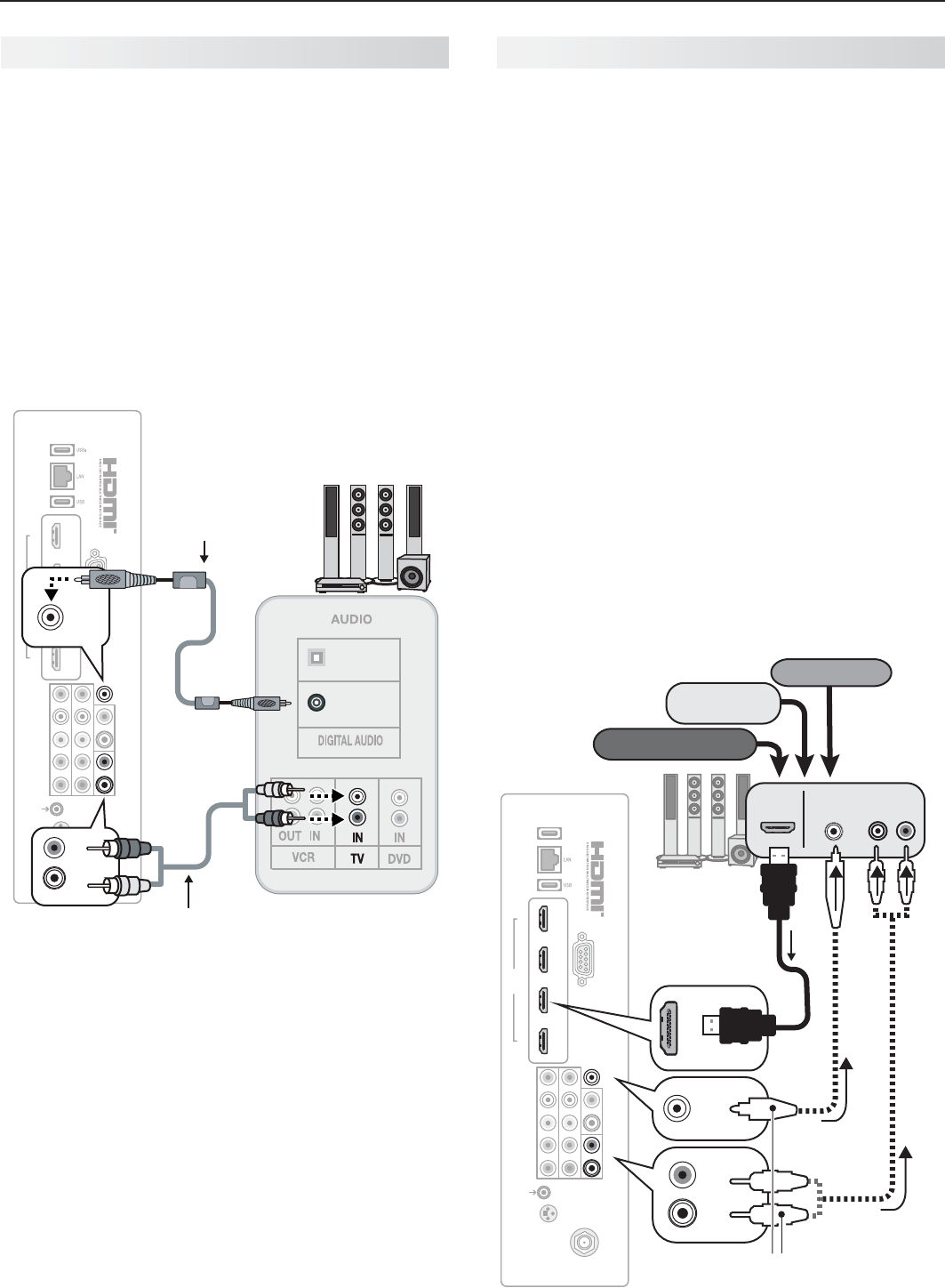
A/V Receiver
Most setups require either a digital audio cable or
analog stereo audio cables. To send audio from TV
channels received on the
ANT
input or devices con-
nected directly to the TV, you must use one of the
connections shown below. Usually, only one of these
connections is required.
The TV makes all audio available in digital and analog
formats:
Analog audio coming into the TV is available as •
output in digital stereo format on the
DIGITAL
AUDIO OUTPUT
jack.
Digital incoming audio is available as analog output •
on the
AVR AUDIO OUTPUT L
and
R
jacks.
1 2 3 4
HDMI
AVR AUDIO OUTPUT
DIGITAL
AUDIO
OUTPUT
RS-232C
3D
GLASSES
EMITTER
ANT
INPUT 2
INPUT 1
DVI/PC L
RL
R
INPUT
IR-
NetCommand
Output/External
Controller Input
Pb Pr
LR
Y/ VIDEO
OPTICAL
INPUT
COAXIAL
INPUT
COAXIAL
INPUT
DIGITAL
AUDIO
OUTPUT
DIGITAL
AUDIO
OUTPUT
AVR AUDIO OUTPUT
L
R
AVR AUDIO OUTPUT
L
R
TV
Digital coaxial
cable (for a digital
A/V receiver)
Stereo analog cables
(for an analog A/V receiver)
A/V receiver
back panel
Note:
On rare occasions, an HDMI signal may be •
copy-restricted and cannot be output from
the TV as a digital signal. To hear these copy-
protected signals through the A/V receiver, use
the connection for an analog A/V receiver.
Check the A/V receiver’s Owner’s Guide for •
information concerning use of the digital input
and switching between digital sound and
analog stereo sound from the TV.
A/V Receiver with HDMI Output
Required: One HDMI-to-HDMI cable
Optional: One digital coaxial audio cable or analog
stereo audio cables
This option allows you to view content from devices
connected to an A/V receiver. The A/V receiver can
send audio and video to the TV over a single HDMI
cable.
In addition to the HDMI connection, you can use •
an audio connection from one of the TV’s audio
outputs. The optional audio connection allows you
to hear, through the A/V receiver, devices con-
nected to the TV only, e.g., an antenna on the
ANT
input.
You may be able to use the TV’s remote control (in •
TV
mode) to operate connected CEC-enabled HDMI
devices. See Appendix C, page 73.
L75-A91.• This setup allows you to use NetCom-
mand-controlled audio and video switching over the
HDMI cable. See “Case 3: Automatic Audio and
Video Switching via HDMI” on page 60.
L75-A91.• To use NetCommand to supplement
HDMI control of a CEC-enabled A/V receiver, note
the recommendations under “More About Using an
HDMI Connection,” page 60.
1 2 3 4
HDMI
AVR AUDIO OUTPUT
DIGITAL
AUDIO
OUTPUT
RS-232C
3D
GLASSES
EMITTER
ANT
INPUT 2
INPUT 1
DVI/PC L
RL
R
INPUT
IR-
NetCommand
Output/External
Controller Input
Pb Pr
LR
Y/ VIDEO
HDMI
OUT
A/V receiver
with HDMI
output
Any connec-
tion types
(can be HD or
SD video)
AUDIO
IN
DIGITAL
AUDIO IN
VCR
Cable box
DVD player
DIGITAL
AUDIO
OUTPUT
DIGITAL
AUDIO
OUTPUT
AVR AUDIO OUTPUT
L
R
L
R
Optional audio
connection
(analog or digital)
TV
HDMI
cable
or

25
In the U.S. call 1(877) 675-2224 for assistance.
Using TV Features
3
Selecting an Input
The Activity menu lets you switch TV inputs. If you named
devices during Auto Input Sensing, the inputs are organized
into groups based on possible ways to use each device.
Dots indicate the number of devices in each group. Note:
Your setup may have only one group (Watch TV).
Press the
1.
ACTIVITY
key.
Use
2.
to move through groups of TV inputs.
Use
3.
to select an input.
Press
4.
ENTER
to switch to the input.
To change the list of inputs shown in each activity group, •
see Inputs > Activity, page 45.
To assign or change the names of input icons, use the •
Inputs > Name menu, page 45.
Sleep Timer
The Sleep Timer turns the TV off after the length of time you set.
To set the TV to turn on at a certain time of day, see the Initial > Timer menu on page
43.
Setting the Sleep Timer
Press
1.
MORE
on the remote control. The TV’s MORE menu will display.
Press
2.
CANCEL
(SLEEP) repeatedly to increase the time in 30-minute increments.
The maximum is 120 minutes.
Press
3.
BACK
or wait five seconds without pressing any keys for the message to dis-
appear.
Viewing the Sleep Timer
Press
INFO
to see the time remaining on the Sleep Timer.
SLEEP
With the MORE menu
displayed, press the
CANCEL key on the
remote control to
activate/deactivate the
Sleep feature.
26 3. Using TV Features
In Canada call 1(800) 450-6487 for assistance.
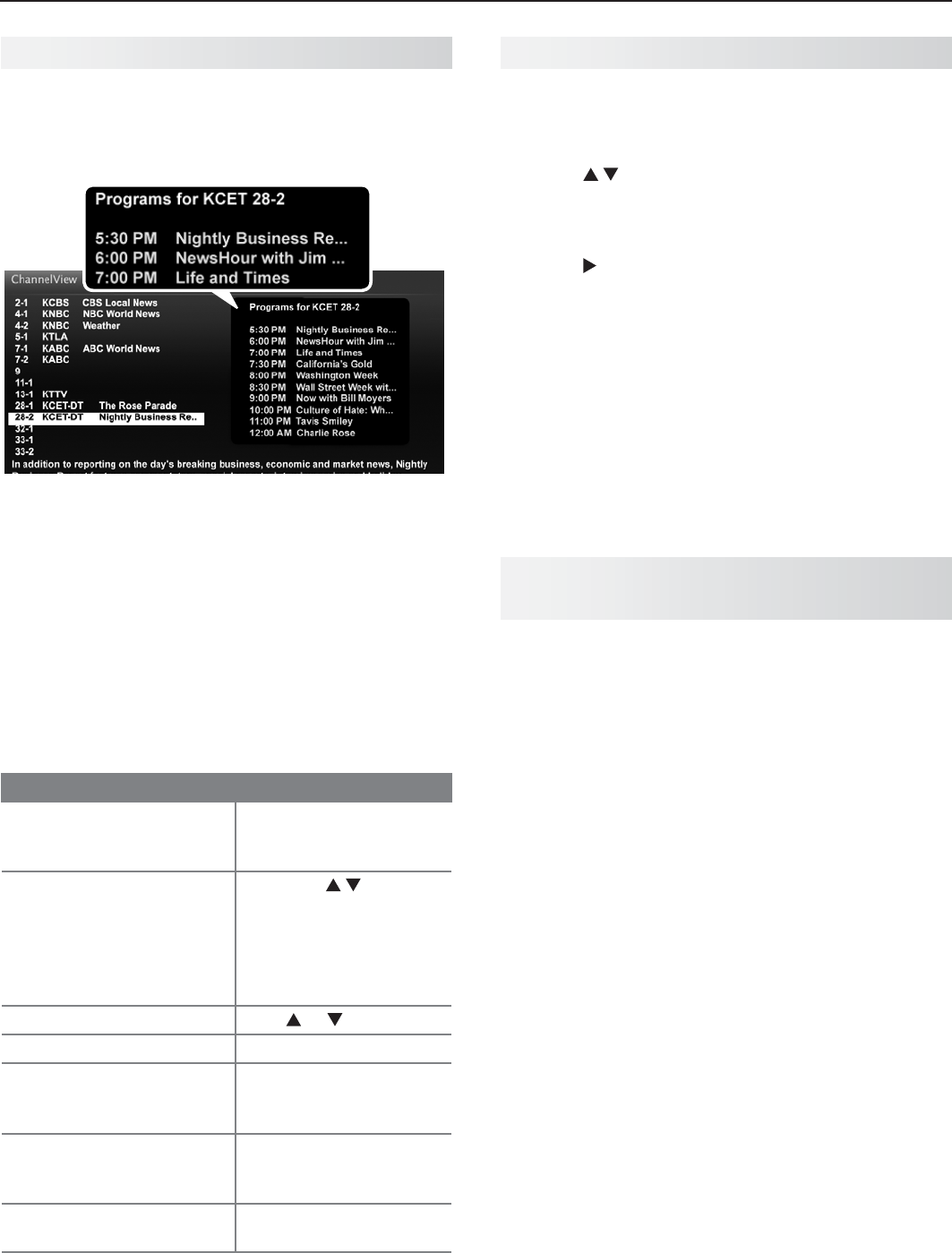
ChannelView Channel Listings
ChannelView displays program descriptions sent by
broadcasters. This information may be unavailable
in some areas.
ChannelView. Programs for the tuned channel are
listed on right side of screen.
ChannelView™ shows memorized channels on the
ANT
input. It displays channel names and program infor-
mation for digital channels as sent by broadcasters or
your local cable service provider (information may be
unavailable in some areas)
.
No program information is
displayed for analog channels.
Note: You must set the TV Clock (page 43)
t
o receive
ChannelView listings for the current channel.
Using ChannelView
Feature Instructions
Display/hide ChannelView
listings from the ANT
input.
GUIDE
Receive updates for a
digital channel.
Press 1. to
highlight a channel
number.
Press the 2.
INFO
key
(the screen may
briefly go blank).
Scan channels one by one. Hold or
Scan channels quickly.
Hold
PAGE UP/PAGE DN
Jump to listings for a spe-
cific channel.
Enter the channel 1.
number.
Press 2.
ENTER
.
See more of the program
description for the current
channel (if available).
INFO
Tune to the highlighted
channel.
ENTER
Redirecting Audio Output
Selecting an Audio Output Device
Press
1.
MORE
and then
9
(AUDIO)
.
Press
2.
to show the Speakers option. The
Speakers option will display only if there is a rec-
ognized audio device on an audio output or HDMI
input.
Press
3.
to select either AV Receiver, Head-
phones, or TV.
Note: The Headphones option displays only if you
selected the name Headphones in the New
Device Found screen.
Disconnecting an Analog A/V Receiver
When you disconnect an analog A/V receiver, change
the Speakers setting to TV to hear sound from the TV
speakers. Change the setting using the remote con-
trol’s
MORE
>
9
(AUDIO
)key or the Adjust > Audio >
Speakers menu.
Controlling A/V Receiver Sound
Volume
Use one of the methods below to control sound volume from
an A/V receiver.
With a Standard TV Setup
Recommended Method:• Program the TV’s
remote control for your A/V receiver and enable the
Audio Lock feature. See page 65.
Program the TV’s remote control for your A/V •
receiver and set the TV remote control’s mode to
AUDIO
. Return the control mode to
TV
to control the
TV.
Use the remote control that came with the A/V •
receiver.
With HDMI Control (CEC-Enabled HDMI
A/V Receiver)
The TV’s remote control may control some functions of
the A/V receiver. See Appendix C, “HDMI Control of
CEC Devices,” page 73.
With NetCommand IR Control
Model L75-A91. Set up NetCommand control of the A/V
receiver’s volume functions in the Inputs > AVR menu.
The TV’s remote will then control A/V receiver volume.
See page 57.

28 3. Using TV Features
In Canada call 1(800) 450-6487 for assistance.
TV Signals and Display Formats
Signal Definitions
480i: Older type of interlaced signals from the
ANT
input,
composite
VIDEO
, component
Y Pb Pr
, or
HDMI
jacks.
480p: Progressive-scan DVD signals on component
Y Pb
Pr
or
HDMI
jacks.
720p and 1080i: High-definition signals received through
component
Y Pb Pr
or
HDMI
jacks. These signals are
always 16:9 (widescreen).
1080p: High-definition signals from a PC or Blu-ray player,
HDMI inputs only.
SD 4:3: Standard-definition squarish-screen-format
signals from digital channels on the
ANT
input.
SD 16:9: Standard-definition widescreen-format signals
from digital channels on the
ANT
input.
HD 16:9: High-definition 16:9 widescreen signals from
digital channels on the
ANT
input.
This is a 16:9 widescreen TV suitable for images available
from HDTV and many DVDs. You can view older-style, squar-
ish images (4:3 aspect ratio) using one of the display formats
described on this page. Press the
MORE
key and then the
0
key (
FORMAT
) to cycle through available display formats.
The TV remembers the format you last used for each input.
DVD Image Definitions
Image information may be stated on the DVD case. Some
DVDs support both of the formats described below.
Anamorphic (or Enhanced for WideScreen TV)
Indicates DVDs recorded to show widescreen images prop-
erly on 16:9 TV sets using the TV’s Standard format mode
(recommended)
.
Non-Anamorphic (or 4:3, 1.33:1, Letter Box, or
Full Screen)
Indicates DVDs recorded for viewing on squarish TV
screens. They may be full screen (4:3 or 1.33:1) which
crops movies to fit the narrow TV, or letter box, which
adds black top and bottom bars.
TV Display Format Definitions
Standard: The full-screen format used by HDTV signals.
Use this format to display anamorphic DVDs with a 1.78:1 or
1.85:1 aspect ratio. Anamorphic DVDs with a 2.35:1 aspect
ratio are displayed correctly but with top and bottom black
bars. Squarish (4:3) images are stretched evenly from side to
side. Available for all signals.
Expand: Enlarges the picture to fill the screen by cropping
the top and bottom; useful for reducing the letter box top and
bottom bars of non-anamorphic DVD images.
Zoom: Enlarges the picture to fill the screen by cropping the
sides, top, and bottom to eliminate black bars.
480i/480p and SD 4:3 signals:• Eliminates top and bottom
bars on anamorphic DVDs with a 2.35:1 aspect ratio.
720p, 1080i, SD 16:9, and HD signals:• Eliminates bars
added to squarish 4:3 images.
Stretch: Stretches a squarish 4:3 image across the
screen to display the entire image with less distortion
than the Standard format.
Stretch Plus:
Similar to Stretch, but minimizes distortion
on the sides by expanding the picture to crop off portions
of the top and bottom. Use to adjust the vertical
position of the picture. L75-A91. Position adjustment may
be unavailable if your NetCommand setup reassigned the
keys for the current device.
Narrow: Displays narrow 4:3 images in their original
shape. Adds black side bars to fill the screen.
Wide Expand: Enlarges the picture, cropping the image on
both sides. Removes or reduces black side bars added to
narrow images converted to 16:9 signals for digital broad-
cast.
Note: All high-definition channels send widescreen
(16:9) signals, but not all programming was created for
the widescreen format. The broadcaster may stretch the
image or add side bars to fill the widescreen area.
Non-anamorphic or SD 4:3
Anamorphic DVD
Standard
Distorted.
Not recom-
mended.
Recommended
Expand
Recom-
mended for
letterbox. See
Note 1.
Distorted; not
recommended.
See Note 1.
Zoom
Distorted.
Not recom-
mended. See
Note 1.
Recommended
for anamorphic
2.35:1 images.
See Note 1.
Stretch
Recom-
mended for
standard
broadcasts.
See Note 1.
Distorted; not
recommended.
See Note 1.
Stretch
Plus
Recom-
mended for
standard
broadcasts.
See Note 1.
Distorted; not
recommended.
See Note 1.
Narrow
See Note 1 Distorted; not
recommended.
See Note 1.
Note 1: Available for 480i, 480p, and digital SD 4:3 signals only.
Original Signal Display Formats
SD 16:9 or
HD Digital
720p, 1080i,
1080p Signal
Wide
Expand
Recommended to re-
move side bars.
Zoom
Recommended to re-
move bars from the top,
bottom, and sides.
TV Display Formats. Press the
MORE
key and then
repeatedly press the
0
key (
FORMAT
)
to see the displays
available for the current program. Press the
INFO
key to
see the name of the display format in use.
Original
Signal
TV
Display

3. Using TV Features 29
In the U.S. call 1(877) 675-2224 for assistance.
To display 3D gaming or 3D cinema content, your
Mitsubishi LASERVUE® TV requires:
A compatible 3D source device•
Either checkerboard or Split HD format •
Active 3D glasses•
The TV’s 3D options are in the Adjust > 3D Mode menu
described on page 41.
Initial Setup
Check if your HDMI 3D video source device outputs
1.
a 1080p 60 Hz signal. This information will be
needed later when you assign an input name in the
New Device Found screen.
If your 3D glasses came with an emitter box,
2.
connect the emitter box to the
3D GLASSES
EMITTER
jack. Place the box in front of the TV
where there is a clear path to the glasses.
Note: If your glasses are marked DLP Link, skip this
step; no emitter box is required with DLP Link
technology.
1 2 3 4
HDMI
AVR AUDIO OUTPUT
DIGITAL
AUDIO
OUTPUT
RS-232C
3D
GLASSES
EMITTER
ANT
INPUT 2
INPUT 1
DVI/PC L
RL
R
INPUT
IR-
NetCommand
Output/External
Controller Input
Pb Pr
LR
Y/ VIDEO
3D
GLASSES
EMITTER
Power on the TV and the source device.
3.
Connect the source device to the TV’s HDMI input.
4.
When the
5.
New Device Found screen displays,
name the input according to the table below. Note
that the TV will process the video signal differently
depending on the name you assign. If your source
device is a Blu-ray disc or game console, the signal
must be 1080p at 60 Hz.
3D Video
Source
3D Video Signal Assign
Name
Computer
Recommended: 1080p 60 Hz (1920
X 1080). The image will fill the TV
screen. Other 60-Hz computer video
signals compatible with the TV will
display with black bars. See page 17.
PC
Other
To see 3D video, the signal must be
1080p 60 Hz
Any other
name
Press
6.
BACK
to close the New Device Found screen.
Watching 3D Video
Note: Active 3D glasses are required.
Press
1.
ACTIVITY
.
Highlight the icon for the 3D video device and press
2.
ENTER
.
Press
3.
MENU
and select the Adjust > 3D Mode
menu.
Select
4.
On for 3D Mode. The On setting will be
memorized for the current input when you exit this
menu.
Select the source format.
5.
Checkerboard is the standard 3D format for •
DLP TV and is compatible with current PC 3D
gaming.
Top/Bottom may be used by some sources and •
can be identified by the screen being divided
into two images, one above the other.
Select the glasses control type
6.
.
For glasses with an emitter box, select • IR
Emitter.
For glasses marked • DLP Link, select DLP Link.
Press
7.
BACK
to close the menu.
If the image does not appear correct
8.
(e.g., objects
appear to be moving in instead of out),
open the
Adjust > 3D Mode menu and set Glasses L-R to
Reverse.
To Watch Regular (non-3D) Content
The 3D Mode setting is memorized for each input.
When you want to watch non-3D images on the input
selected above, open the Adjust > 3D Mode menu and
set 3D Mode to Off.
3D Video
32 3. Using TV Features
In Canada call 1(800) 450-6487 for assistance.
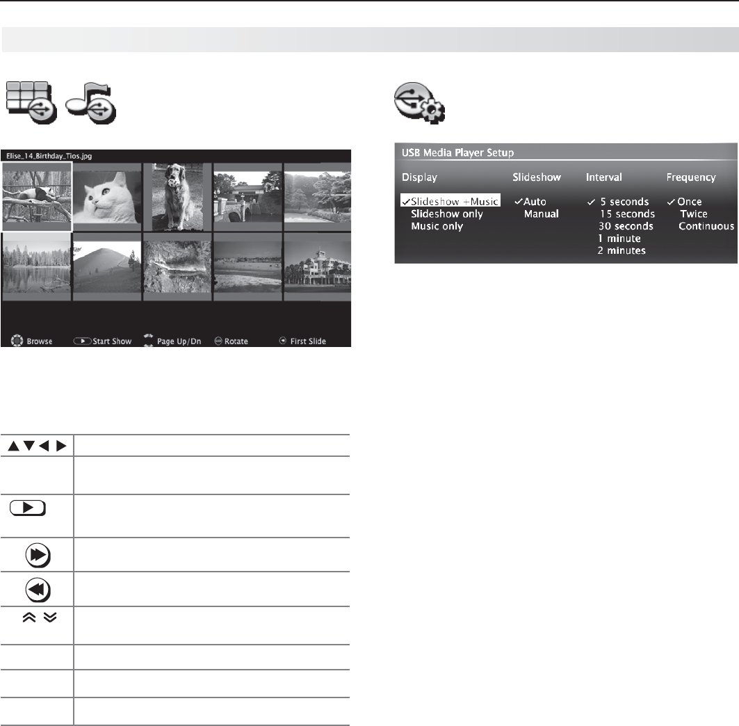
Thumbnail and Playlist
Menus
JPEG Thumbnail Menu
Use these keys while viewing JPEG thumbnail images
or the music tracks in a playlist.
Moves the highlight from item to item.
GUIDE
Rotates a thumbnail clockwise in 90˚
increments
or
ENTER
Plays the slide show or playlist starting
with the highlighted item.
Selects the last item on the current page.
Selects the first item on the current page.
PAGE UP/DN
Displays the next or previous page of
items.
BACK
Displays the USB Media Player menu.
MENU
Displays the main menu.
ACTIVITY
Displays the Activity menu.
Notes on Using the USB Port
• TheTVignoresallcommandswhilereadingfiles.
Wait
until the Play icon appears highlighted and in full
color before continuing.
• Largefilesorhigh-capacitystoragedevicesmaytakea
long time to display.
•
The TV can read files up to 10 MB in size with a
maximum of 2,500 files stored on the device. The
FAT16 or FAT32 file system is recommended.
• UseaUSBdriveinsteadofacardreader.
• BackupthedataonyourUSBdrivebeforecon-
necting it to the TV. Mitsubishi is not responsible
for any file damage or data loss.
Note:
Some manufacturers’ USB devices may be incom-
patible with the TV. If the TV is unable to display
your photos, you can:
• Transfer
files to a different USB device.
• Useyourdigitalcamera’scompositevideo
output. See page 33.
Picture Files Compatible with the USB Port
• Stillimagesrecordedondigitalcamerasusingthe
Exchangeable Image File Format, version 2.1 (EXIF
2.1) standard for digital still cameras and Design
Rules for Camera File Systems version 1.0 (DCF 1.0)
• Someimagesopenedandresavedonacomputer
may not play back or may not display in the thumb-
nail list. This happens if the files were resaved in an
incompatible format.
• Fullpathfilenamescanbenolongerthan50char-
acters and must end in a .jpg extension. Only the
first 20 of the 50 characters will display.
Camera and Music Files, continued
USB Media Setup Menu
Use the USB Media Setup menu set up play of a slide
show or playlist.
• IfJPEGimagefilesandmp3filesareontheUSB
device, choose:
Slideshow + Music -
Slideshow -
Music only -
Slideshow.• Select either Auto or Manual advance
for the slide show. During manual operation, press
ENTER
to advance to the next slide.
Interval.• For automatic advance, select the time
interval for display of each slide. The interval you
select here is the minimum time between slides;
actual time may be longer for larger files.
Frequency.•
For automatic advance, select the
number of times (frequency) to play the complete slide
show and/or playlist:
Once, Twice, or Continuous.
Press •
BACK
to close the Media Setup menu and
return to the Media Player menu.
34 3. Using TV Features
In Canada call 1(800) 450-6487 for assistance.
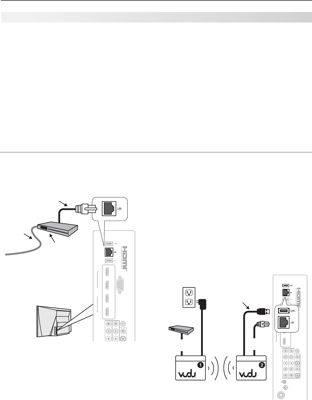
Streaming Internet Movies with VUDU
L75-A91. This TV’s built-in VUDU™ capabilities allow
you to access your own personal home video store
right on your TV. VUDU’s service offers you:
The largest on-demand HD movie selection any-•
where, featuring full 1080p and 5.1 surround sound.
All of Hollywood’s latest hits and classics. Movies •
are available to rent or buy the same day the movie
comes out on DVD.
VUDU allows you to enjoy movies with no store •
visits, no mailing, no late fees and no subscriptions.
Parental controls allow you to restrict access to •
content according to MPAA ratings. See the VUDU
Info & Settings menu.
VUDU features popular internet applications provid-•
ing free content.
At the time of this writing, VUDU requires an internet
bandwidth of 4.0 Mbps or higher for instant HD video
and 2.0 Mbps or higher for instant SD video. These
specifications are subject to change. Visit www.VUDU.
com to learn more about available titles, prices, recom-
mended bandwidth, and services offered. For a list of
recommended routers and switches, see the Support >
FAQ section at VUDU.com.
Required for VUDU Service
Broadband internet service•
Ethernet cable • or the VUDU wireless kit.
Computer access to the VUDU.com website •
(required for one-time account activation).
A credit card for rental and purchase transactions.•
Standard Connection
Connect the TV to your network router or directly to a
high-speed internet modem using an Ethernet cable
(not supplied).
1 2 3 4
HDMI
AVR AUDIO OUTPUT
DIGITAL
AUDIO
OUTPUT
RS-232C
DVI/PC L
RL
R
INPUT
Pb Pr
LR
Y/ VIDEO
Ethernet
cable
TV
Internet
router or
modem
Incoming
high-speed
internet
service
Standard VUDU connection via Ethernet
VUDU Wireless Kit
The VUDU wireless kit is available for purchase from
VUDU.com. The kit includes the two wireless boxes,
two power cables, and two Ethernet cables shown in
the diagram below. VUDU capabilities are built right
into the TV, so connect VUDU Wireless Box 2 directly
to the TV as shown.
The LED indicators for •
POWER
and
ETHERNET
will
light up once power is applied to the boxes.
After a few seconds, the LED indicator for •
WIRELESS
will start to blink, indicating the wireless
adapters have been set up successfully.
The LED indicators for •
WIRELESS
and
ETHERNET
will blink when data is being transmitted.
L
1 2 3 4
HDMI
AVR AUDIO OUTPUT
DIGITAL
AUDIO
OUTPUT
RS-232C
3D
GLASSES
EMITTER
ANT
INPUT 2
INPUT 1
DVI/PC L
RL
R
INPUT
IR-
NetCommand
Output/External
Controller Input
Pb Pr
LR
Y/ VIDEO
USB-to-DC
power cable
AC-to-DC
power
cable
VUDU Wire-
less Box 2
Router
or modem
Ethernet
cable
Ethernet
cable
VUDU Wire-
less Box 1
TV
Connecting the VUDU wireless kit. Connect VUDU
Wireless Box 2 directly to the TV.

37
In the U.S. call 1(877) 675-2224 for assistance.
4TV Menus
Displays or clears the main menu.
Moves up one menu level.•
Clears the current menu.•
Moves navigation into options •
area.
Selects an item.•
Moves the highlight within menus.
Makes adjustments in some
menus.
Look for the key guide at
the bottom of each menu.
Main Menu
Press
MENU
on the remote control to open the main menu and then select from one of these categories.
Adjust Customize picture and sound settings; enable 3D mode. 38
Captions Turn closed captions on and off; customize caption displays. 42
Initial Perform basic TV setup. Set language, scan (memorize) channels and edit
channel options, set the TV clock, set auto-on TV Timer. 43
Input Assign names to TV inputs, enable HDMI Control, assign activities to inputs.
Model L75-A91. Perform NetCommand IR “learning.” 45
Lock Restrict TV use. Disable the control-panel buttons. Set a pass code. 47
Menu Navigation
Termékspecifikációk
| Márka: | Mitsubishi |
| Kategória: | 3D TV |
| Modell: | L75-A91 Laservue |
Szüksége van segítségre?
Ha segítségre van szüksége Mitsubishi L75-A91 Laservue, tegyen fel kérdést alább, és más felhasználók válaszolnak Önnek
Útmutatók 3D TV Mitsubishi

19 Augusztus 2024
15 Augusztus 2024
Útmutatók 3D TV
Legújabb útmutatók 3D TV

4 Július 2024
2 Július 2024
1 Július 2024

1 Július 2024
29 Június 2024
29 Június 2024
29 Június 2024