Használati útmutató Mercedes C-Class 2017
Mercedes
Személygépkocsi
C-Class 2017
Olvassa el alább 📖 a magyar nyelvű használati útmutatót Mercedes C-Class 2017 (370 oldal) a Személygépkocsi kategóriában. Ezt az útmutatót 10 ember találta hasznosnak és 2 felhasználó értékelte átlagosan 4.5 csillagra
Oldal 1/370

C-Class
Operator's Manual
Your Operator's Manual
Digital form inside the vehicle
Familiarize yourself with the contents of the Operator's Manual directly via your
vehicle's multimedia system (Menu item "Vehicle").
Booklet inside the vehicle
In addition to the vehicle's Operator's Manual, you can obtain the complete multi-
media system Supplement from your authorized Mercedes-Benz Center.
Digital form via the Internet
You can find the Operator's Manual on the Mercedes-Benz homepage.
Digital form as an App
The Mercedes-Benz Guides App is available for free on the Apple®App store or Google
Play.
Apple® iOS Android™
Order no. P205 0626 13 Part no. 205 584 19 10 Edition B 2017
É2055841910HËÍ
2055841910
C-Class Operator's Manual

Publication details
Internet
Further information about Mercedes-Benz vehi-
cles and about Daimler AG can be found on the
following websites:
http://www.mbusa.com (USA only)
http://www.mercedes-benz.ca (Canada only)
Editorial office
Daimler AG: not to be reprinted, translated or
otherwise reproduced, in whole or in part, with-
out written permission from Daimler AG.
Vehicle manufacturer
Daimler AG
Mercedesstrae 137
70327 Stuttgart
Germany
Symbols
Registered trademarks:
RBluetooth®is a registered trademark of Blue-
tooth SIG Inc.
RDTS™ is a registered trademark of DTS, Inc.
RDolby®and MLP™ are registered trademarks
of DOLBY Laboratories.
RBabySmart™, ESP®and PRE-SAFE®are reg-
istered trademarks of Daimler AG.
RHomeLink®is a registered trademark of John-
son Controls.
RiPod®and iTunes®are registered trademarks
of Apple Inc.
RBurmester®is a registered trademark of
Burmester Audiosysteme GmbH.
RMicrosoft®and Windows media®are regis-
tered trademarks of Microsoft Corporation.
RSIRIUS®is a registered trademark of Sirius
XM Radio Inc.
RHD Radio™ is a registered trademark of iBiq-
uity Digital Corporation.
RGracenote®is a registered trademark of
Gracenote, Inc.
RZAGAT Survey®and related brands are regis-
tered trademarks of Zagat Survey, LLC.
In this Operator's Manual you will find the fol-
lowing symbols:
GWARNING
Warning notes make you aware of dangers
which could pose a threat to your health or
life, or to the health and life of others.
HEnvironmental note
Environmental notes provide you with infor-
mation on environmentally aware actions or
disposal.
!Notes on material damage alert you to dan-
gers that could lead to damage to your vehi-
cle.
iPractical tips or further information that
could be helpful to you.
XThis symbol indicates an
instruction that must be fol-
lowed.
XSeveral of these symbols in
succession indicate an
instruction with several
steps.
(Y
page)
This symbol tells you where
you can find more informa-
tion about a topic.
YY This symbol indicates a
warning or an instruction
that is continued on the next
page.
Dis‐
play
This text indicates a mes-
sage on the multifunction
display/multimedia display.
As at 08.04.2016

Welcome to the world of Mercedes-Benz
We urge you to read this Operator's Manual
carefully and familiarize yourself with the vehi-
cle before driving. For your own safety and a
longer vehicle life, follow the instructions and
warning notices in this Operator's Manual.
Ignoring them could result in damage to the
vehicle or personal injury to you or others.
Vehicle damage caused by failure to follow
instructions is not covered by the Mercedes-
Benz Limited Warranty.
The equipment or product designation of your
vehicle may vary depending on:
RModel
ROrder
RCountry specification
RAvailability
Mercedes-Benz therefore reserves the right to
introduce changes in the following areas:
RDesign
REquipment
RTechnical features
The equipment in your vehicle may therefore
differ from that shown in the descriptions and
illustrations.
The following are integral components of the
vehicle:
RDigital Operator's Manual
RPrinted Operator's Manual
RMaintenance Booklet
REquipment-dependent supplements
Keep these documents in the vehicle at all
times. If you sell the vehicle, always pass all
documents on to the new owner.
Your Operator's Manual:
Digital form inside the vehicle
The Digital Operator's Manual provides
comprehensive and specifically adapted
information on your vehicle's equipment
and multimedia system. It contains infor-
mative animations, individual language
settings and an intuitive search function.
Booklet inside the vehicle
In addition to this manual and the afore-
mentioned digital media, you also have the
option to obtain a comprehensive printed
version of the Supplement for your multi-
media system from your authorized
Mercedes-Benz Center.
Digital form via the Internet
The Operator's Manual on the Internet pro-
vides easy access to all information
regarding your vehicle and multimedia sys-
tem. It also provides helpful animations,
interesting background information and a
wide array of search options.
Digital form as an App
Using the Mercedes-Benz Guides App, you
can view all the information on your vehicle
and multimedia system via mobile Internet
or download it independently of network
access. Available for smartphones or tab-
lets.
Please note that the Mercedes-Benz Guides App
may not yet be available in your country.
Mercedes-Benz USA, LLC
Mercedes-Benz Canada, Inc.
A Daimler Company
2055841910 É2055841910HËÍ

Setting the air vents ...................... 133
Setting the airflow ......................... 128
Setting the climate mode ............... 127
Setting the climate mode (multi-
media system) ............................... 271
Setting the temperature ................ 128
Switching air-recirculation mode
on/off ............................................ 130
Switching on/off ........................... 126
Switching residual heat on/off ...... 131
Switching the rear window
defroster on/off ............................ 130
Switching the synchronization
function on and off ........................ 129
Synchronization function (multi-
media system) ............................... 272
Climate control settings
Multimedia system ........................ 270
Climate control system
Climate control .............................. 126
Cockpit
Overview .......................................... 35
COLLISION PREVENTION ASSIST
PLUS
Activating/deactivating ................. 219
Display message ............................ 232
Operation/notes .............................. 67
COMAND display
Cleaning ......................................... 309
Combination switch .......................... 114
Connecting a USB device
see also Digital Operator's Man-
ual .................................................. 266
Consumption statistics (on-board
computer) .......................................... 212
Controller ........................................... 267
Controlling speed
see DISTRONIC PLUS
Convenience box ............................... 282
Convenience closing feature .............. 92
Convenience opening feature ............ 92
Coolant (engine)
Checking the level ......................... 302
Display message ............................ 239
Filling capacity ............................... 363
Important safety notes .................. 362
Temperature display in the instru-
ment cluster .................................. 208
Warning lamp ................................. 261
Cooling
see Climate control
Copyright ............................................. 34
Cornering light function
Display message ............................ 238
Function/notes ............................. 115
Crosswind Assist ................................. 73
Cruise control
Cruise control lever ....................... 168
Deactivating ................................... 169
Display message ............................ 247
Driving system ............................... 167
Function/notes ............................. 167
General notes ................................ 167
Important safety notes .................. 167
Setting a speed .............................. 168
Storing and maintaining current
speed ............................................. 168
Storing the current speed or call-
ing up the last stored speed .......... 168
Cup holder
Center console .............................. 285
Important safety notes .................. 285
Rear compartment ......................... 285
Customer Assistance Center
(CAC) ..................................................... 31
Customer Relations Department ....... 31
D
Data
see Technical data
Data carrier
Selecting ........................................ 216
Daytime running lamps
Display message ............................ 238
Function/notes ............................. 113
Switching on/off (on-board com-
puter) ............................................. 221
DEF
Adding ........................................... 156
Display message ............................ 242
Displaying level and range ............. 218
Filling capacity ............................... 361
Important safety notes .................. 361
8Index

Low outside temperatures .............361
Purity ............................................. 361
DEF®
Additives ........................................ 361
Diagnostics connection ......................31
Diesel .................................................. 360
Digital Operator's Manual
Help .................................................26
Introduction .....................................26
Digital speedometer.........................212
DIRECT SELECT lever
Automatic transmission ................. 146
Display
see Display messages
see Warning and indicator lamps
Display messages
ASSYST PLUS ................................ 303
Calling up (on-board computer) ..... 226
Driving systems .............................243
Engine ............................................ 239
General notes ................................ 226
Hiding (on-board computer) ........... 226
Introduction ................................... 226
Lights ............................................. 238
Safety systems .............................. 227
SmartKey ....................................... 253
Tires ............................................... 248
Vehicle ...........................................250
Distance recorder .............................211
Distance warning (warning lamp) .... 263
Distance warning function
Function/notes ................................ 68
Distance warning system
see COLLISION PREVENTION
ASSIST PLUS
DISTRONIC PLUS
Activating ....................................... 171
Activation conditions ..................... 171
Cruise control lever ....................... 171
Deactivating ................................... 174
Display message ............................ 245
Displays in the instrument cluster .. 173
Driving tips ....................................175
Driving with DISTRONIC PLUS ....... 172
Function/notes .............................169
Important safety notes .................. 170
Setting a speed .............................. 173
Setting the specified minimum
distance ......................................... 173
Stopping ........................................ 172
with Steering Assist and Stop&Go
Pilot ............................................... 175
Doors
Automatic locking (switch) ...............85
Central locking/unlocking
(SmartKey) .......................................78
Control panel ...................................42
Display message ............................ 252
Emergency locking ........................... 85
Emergency unlocking ....................... 85
Important safety notes .................... 84
Opening (from inside) ...................... 84
Drinking and driving ......................... 163
Drive program
Automatic transmission ................. 149
SETUP (on-board computer,
Mercedes-AMG vehicles) ............... 223
Drive programs
Display (DIRECT SELECT lever) ...... 147
DYNAMIC SELECT switch .............. 144
Driver's door
see Doors
Driving abroad
Mercedes-Benz Service ................. 304
Driving Assistance PLUS package ... 201
Driving on flooded roads .................. 166
Driving safety system
Crosswind Assist ............................. 73
Driving safety systems
ABS (Anti-lock Braking System) ....... 65
ADAPTIVE BRAKE ............................. 73
Adaptive Brake Assist ...................... 69
BAS (Brake Assist System) .............. 65
BAS PLUS with Cross-Traffic
Assist ............................................... 66
COLLISION PREVENTION ASSIST
PLUS ................................................ 67
Distance warning function ............... 68
EBD (electronic brake force distri-
bution) ............................................. 73
ESP®(Electronic Stability Pro-
gram) ............................................... 70
Important safety information ........... 65
Overview .......................................... 64
Index 9

PRE-SAFE®Brake ............................. 73
STEER CONTROL ............................. 75
Driving system
RACE START (Mercedes-AMG
vehicles) ........................................178
Driving systems
360°camera .................................. 192
Active Blind Spot Assist ................. 201
Active Lane Keeping Assist ............ 204
Active Parking Assist ..................... 184
AIRMATIC ...................................... 179
AMG adaptive sport suspension
system ...........................................180
ATTENTION ASSIST ........................ 196
Blind Spot Assist ............................ 198
Cruise control ................................ 167
Display message ............................ 243
DISTRONIC PLUS ........................... 169
DISTRONIC PLUS with Steering
Assist and Stop&Go Pilot ...............175
Driving Assistance Plus package ... 201
HOLD function ............................... 177
Lane Keeping Assist ......................200
Lane Tracking package .................. 198
PARKTRONIC ................................. 181
Rear view camera .......................... 188
Traffic Sign Assist .......................... 197
Driving tips
AMG ceramic brakes ..................... 166
Automatic transmission ................. 148
Brakes ...........................................164
Break-in period .............................. 135
DISTRONIC PLUS ........................... 175
Downhill gradient ........................... 164
Drinking and driving ....................... 163
Driving in winter .............................167
Driving on flooded roads ................ 166
Driving on wet roads ......................166
Exhaust check ............................... 163
Fuel ................................................ 162
General .......................................... 162
Hydroplaning ................................. 166
Icy road surfaces ........................... 167
Important safety notes .................. 135
Limited braking efficiency on sal-
ted roads ....................................... 165
Snow chains .................................. 332
Subjecting brakes to a load ........... 165
The first 1000 miles (1500 km) ..... 135
Wet road surface ........................... 165
DTR+
Display message ............................ 247
DVD video
Operating (on-board computer) ..... 216
see also Digital Operator's Man-
ual ..................................................266
DYNAMIC SELECT switch
Automatic transmission ................. 144
Climate control (dual-zone auto-
matic climate control) .................... 126
E
EASY-ENTRY feature
Function/notes .............................107
EASY-EXIT feature
Function/notes .............................107
EASY-PACK trunk box ....................... 282
EBD (electronic brake force distri-
bution)
Display message ............................ 229
Function/notes ................................ 73
ECO display
Function/notes .............................163
On-board computer ....................... 212
ECO start/stop function
Automatic engine start .................. 141
Automatic engine switch-off .......... 141
Deactivating/activating ................. 141
General information ....................... 140
Important safety notes .................. 140
Introduction ................................... 140
Electronic Stability Program
see ESP®(Electronic Stability Program)
Emergency
Automatic measures after an acci-
dent ................................................. 58
Emergency release
Driver's door ....................................85
Trunk ............................................... 90
Vehicle ............................................. 85
Emergency Tensioning Devices
Activation ......................................... 55
Emissions control
Service and warranty information ....28
10 Index

Engine
Check Engine warning lamp ...........261
Display message ............................ 239
ECO start/stop function ................ 140
Engine number ............................... 358
Irregular running ............................ 143
Jump-starting ................................. 321
Starting (important safety notes) ... 138
Starting problems .......................... 143
Starting the engine with the
SmartKey ....................................... 138
Starting via smartphone ................ 139
Starting with the Start/Stop but-
ton ................................................. 138
Switching off .................................. 160
Tow-starting (vehicle) ..................... 326
Engine electronics
Problem (malfunction) ................... 143
Engine oil
Adding ...........................................301
Additives ........................................ 362
Checking the oil level ..................... 300
Checking the oil level using the
dipstick .......................................... 301
Display message ............................ 241
Filling capacity ............................... 362
General notes ................................ 361
Notes about oil grades ................... 361
Notes on oil level/consumption .... 300
Temperature (on-board computer,
Mercedes-AMG vehicles) ...............223
Entering an address
see also Digital Operator's Man-
ual ..................................................266
ESP®(Electronic Stability Pro-
gram)
AMG menu (on-board computer) ... 223
Characteristics ................................. 70
Crosswind Assist .............................73
Deactivating/activating (button
in Mercedes-AMG vehicles) .............71
Deactivating/activating (notes,
except Mercedes-AMG vehicles) ...... 71
Deactivating/activating (on-
board computer, except
Mercedes-AMG vehicles) ............... 219
Display message ............................ 227
Function/notes ................................ 70
General notes .................................. 70
Important safety information ........... 70
Trailer stabilization ........................... 73
Warning lamp ................................. 257
ETS/4ETS (Electronic Traction Sys-
tem) ...................................................... 70
Exhaust
see Exhaust pipe
Exhaust check ................................... 163
Exhaust pipe
Cleaning ......................................... 309
Exterior lighting
Cleaning ......................................... 308
Setting options .............................. 113
see Lights
Exterior mirrors
Adjusting ....................................... 108
Dipping (automatic) ....................... 109
Folding in/out (automatically) ....... 109
Folding in/out (electrically) ........... 109
Out of position (troubleshooting) ... 109
Setting ........................................... 109
Storing settings (memory func-
tion) ............................................... 111
Storing the parking position .......... 110
Eyeglasses compartment ................. 277
F
Favorites
Overview ........................................ 269
Features ............................................. 285
Filler cap
see Refueling
Flat tire
Changing a wheel/mounting the
spare wheel ................................... 349
MOExtended tires .......................... 314
Preparing the vehicle ..................... 313
TIREFIT kit ...................................... 315
Floormats ........................................... 298
Frequencies
Mobile phone ................................. 356
Two-way radio ................................ 356
Front wheel arch
Removing/installing the cover ....... 119
Front wheel arch cover
Installing/removing ....................... 119
Index 11

Fuel
Additives ........................................ 360
Consumption statistics .................. 212
Diesel ............................................ 360
Displaying the current consump-
tion ................................................ 212
Displaying the range ...................... 212
Driving tips .................................... 162
Fuel gauge .......................................36
Grade (gasoline) ............................ 359
Important safety notes .................. 359
Low outside temperatures .............361
Problem (malfunction) ................... 156
Quality (diesel) ............................... 360
Refueling ........................................ 154
Tank content/reserve fuel ............. 359
Fuel filler flap
Closing ........................................... 155
Fuel filter (display message) ............ 242
Fuel level
Calling up the range (on-board
computer) ...................................... 212
Fuel tank
Capacity ........................................ 359
Problem (malfunction) ................... 156
Fuses
Allocation chart ............................. 328
Before changing ............................. 327
Dashboard fuse box ....................... 327
Fuse box in the engine compart-
ment .............................................. 327
Fuse box in the front-passenger
footwell .......................................... 327
Fuse box in the trunk ..................... 328
Important safety notes .................. 326
G
G-Meter (on-board computer,
Mercedes-AMG vehicles) .................. 223
Garage door opener
Clearing the memory ..................... 298
General notes ................................ 295
Important safety notes .................. 296
Opening/closing the garage door..298
Problems when programming ........297
Programming (button in the rear-
view mirror) ................................... 296
Synchronizing the rolling code ....... 297
Gear indicator (on-board com-
puter, Mercedes-AMG vehicles) ....... 223
Genuine parts ...................................... 27
Glove box ...........................................277
Google™ Local Search
see also Digital Operator's Man-
ual ..................................................266
H
Handbrake
see Parking brake
HANDS-FREE ACCESS .......................... 88
Handwriting recognition
Switching text reader function
on/off ............................................ 269
Touchpad ....................................... 268
Hazard warning lamps ......................115
Head restraints
Adjusting (electrically) ................... 103
Adjusting (manually) ......................103
Adjusting (rear) .............................. 103
Adjusting the fore-and-aft posi-
tion manually ................................. 103
General notes ................................ 102
Important safety notes .................. 102
Installing/removing (rear) .............. 103
Head-up display
Adjusting the brightness ................ 221
Displays and operating .................. 210
Function/notes .............................210
Important safety notes .................. 210
Selecting displays .......................... 220
Setting the position ....................... 221
Storing settings (memory func-
tion) ............................................... 111
Headlamps
Display message ............................ 238
Fogging up ..................................... 116
see Automatic headlamp mode
Heating
see Climate control
High beam flasher .............................114
High-beam headlamps
Adaptive Highbeam Assist ............. 115
Display message ............................ 238
Replacing bulbs .............................118
12 Index

Switching on/off ........................... 114
Hill start assist .................................. 140
HOLD function
Activating ....................................... 177
Activation conditions ..................... 177
Deactivating ................................... 178
Display message ............................ 245
Function/notes ............................. 177
General notes ................................ 177
Home address
see also Digital Operator's Man-
ual .................................................. 266
Hood
Closing ........................................... 300
Display message ............................ 251
Important safety notes .................. 299
Opening ......................................... 299
Horn ...................................................... 35
HUD
see Head-up display
Hydroplaning ..................................... 166
I
Ignition lock
see Key positions
Immobilizer .......................................... 76
Indicator and warning lamps
COLLISION PREVENTION ASSIST
PLUS .............................................. 263
Indicator lamp
Replacing bulbs (rear) .................... 119
Indicator lamps
see Warning and indicator lamps
Indicators
see Turn signals
Insect protection on the radiator .... 300
Instrument cluster
Overview .......................................... 36
Warning and indicator lamps ........... 36
Instrument cluster lighting .............. 207
Interior lighting
Automatic control .......................... 117
Control ........................................... 117
Overview ........................................ 116
Reading lamp ................................. 116
iPod®
see also Digital Operator's Man-
ual .................................................. 266
J
Jack
Using ............................................. 350
Jump starting (engine) ...................... 321
K
Key positions
SmartKey ....................................... 136
Start/Stop button .......................... 137
KEYLESS-GO
Activating ......................................... 79
Convenience closing feature ............ 92
Deactivation ..................................... 79
Locking ............................................ 79
Removing the Start/Stop button ... 137
Start function ................................... 80
Unlocking ......................................... 79
Kickdown
Driving tips .................................... 149
Manual gearshifting ....................... 153
Knee bag .............................................. 50
L
Lamps
see Warning and indicator lamps
Lane Keeping Assist
Activating/deactivating ................. 201
Activating/deactivating (on-
board computer) ............................ 220
Display message ............................ 244
Function/information .................... 200
see Active Lane Keeping Assist
Lane Tracking package ..................... 198
Lap time (RACETIMER) ...................... 224
LATCH-type (ISOFIX) child seat
anchors ................................................ 61
License plate lamp (display mes-
sage) ................................................... 238
Light function, active
Display message ............................ 238
Light switch
Operation ....................................... 113
Index 13

Lights
Adaptive Highbeam Assist .............115
Automatic headlamp mode ............ 113
Cornering light function ................. 115
Fogged up headlamps .................... 116
General notes ................................ 113
Hazard warning lamps ................... 115
High beam flasher .......................... 114
High-beam headlamps ................... 114
Light switch ................................... 113
Low-beam headlamps .................... 114
Parking lamps ................................ 114
Rear fog lamp ................................ 114
Setting exterior lighting ................. 113
Standing lamps .............................. 114
Switching the daytime running
lamps on/off (on-board com-
puter) ............................................. 221
Turn signals ................................... 114
see Interior lighting
Loading guidelines ............................ 276
Locking
see Central locking
Locking (doors)
Automatic ........................................ 85
Emergency locking ........................... 85
From inside (central locking but-
ton) ..................................................84
Locking centrally
see Central locking
Low-beam headlamps
Display message ............................ 238
Replacing bulbs .............................118
Switching on/off ........................... 114
Lumbar support
Adjusting the 4-way lumbar sup-
port ................................................ 104
M
M+S tires ............................................ 331
Malfunction message
see Display messages
Matte finish (cleaning instruc-
tions) ..................................................307
mbrace
Call priority ....................................292
Display message ............................ 232
Downloading destinations
(COMAND) ..................................... 292
Downloading routes ....................... 295
Emergency call .............................. 289
General notes ................................ 288
Geo fencing ................................... 295
Info call button .............................. 291
Locating a stolen vehicle ...............294
Remote fault diagnosis .................. 294
Remote vehicle locking .................. 293
Roadside assistance button ........... 290
Search & Send ............................... 292
Self-test ......................................... 289
Speed alert .................................... 295
System .......................................... 289
Triggering the vehicle alarm ........... 295
Vehicle remote unlocking .............. 293
Mechanical key
Function/notes ................................ 80
General notes .................................. 80
Inserting .......................................... 80
Locking vehicle ................................ 85
Removing ......................................... 80
Unlocking the driver's door .............. 85
Media Interface
see Digital Operator's Manual
Memory card (audio) ......................... 216
Memory function
Seats, steering wheel, exterior
mirrors ........................................... 111
Mercedes-Benz Intelligent Drive
360°camera .................................. 192
Active Blind Spot Assist ................. 201
Active Lane Keeping Assist ............ 204
Active Parking Assist ..................... 184
ATTENTION ASSIST ........................ 196
Blind Spot Assist ............................ 198
DISTRONIC PLUS ........................... 169
DISTRONIC PLUS with Steering
Assist and Stop&Go Pilot ............... 175
General notes ................................ 167
Lane Keeping Assist ...................... 200
PARKTRONIC ................................. 181
PRE-SAFE®(anticipatory occu-
pant protection) ............................... 57
PRE-SAFE®PLUS (anticipatory
occupant protection PLUS) .............. 58
14 Index

Rear viewcamera .......................... 188
Traffic SignAssist.......................... 197
Messagememory (on-board com-
puter).................................................. 226
Messages
see Display messages
see Warningand indicatorlamps
Mirrorturn signal
Cleaning.........................................308
Mirrors
see Exterior mirrors
see Rear-view mirror
see Vanity mirror (in the sun visor)
Mobile phone
Connecting (Bluetooth®inter-
face) .............................................. 273
Connecting another mobile
phone ............................................ 274
Frequencies ................................... 356
Installation ..................................... 356
Menu (on-board computer) ............ 217
Transmission output (maximum) .... 356
Modifying the programming
(SmartKey) ...........................................80
MOExtended tires .............................. 314
Mounting wheels
Lowering the vehicle ...................... 354
Mounting a new wheel ................... 353
Preparing the vehicle .....................350
Raising the vehicle ......................... 350
Removing a wheel .......................... 353
Securing the vehicle against roll-
ing away ........................................ 350
MP3
Operation ....................................... 216
see also Digital Operator's Man-
ual ..................................................266
Multifunction display
Function/notes .............................209
Multifunction steering wheel
Operating the on-board computer .. 208
Overview .......................................... 37
Multimedia system
Switching on and off ......................267
Music files
see also Digital Operator's Man-
ual .................................................. 266
N
Navigation
Displaying (on-board computer) ..... 213
Menu (on-board computer) ............ 213
see also Digital Operator's Man-
ual .................................................. 266
Notes on breaking-in a new vehi-
cle ....................................................... 135
O
Occupant Classification System
(OCS)
Conditions ....................................... 51
Faults ............................................... 54
Operation ......................................... 51
System self-test ............................... 53
Occupant safety
Air bags ........................................... 48
Automatic measures after an acci-
dent ................................................. 58
Children in the vehicle ..................... 59
Important safety notes .................... 43
Introduction to the restraint sys-
tem .................................................. 43
Occupant Classification System
(OCS) ............................................... 51
PASSENGER AIR BAG indicator
lamps ............................................... 44
Pets in the vehicle ........................... 64
PRE-SAFE®(anticipatory occu-
pant protection) ............................... 57
PRE-SAFE®PLUS (anticipatory
occupant protection PLUS) .............. 58
Restraint system warning lamp ........ 44
Seat belt .......................................... 44
OCS
Conditions ....................................... 51
Faults ............................................... 54
Operation ......................................... 51
System self-test ............................... 53
Odometer ........................................... 211
Oil
see Engine oil
On-board computer
AMG menu ..................................... 223
Assistance graphic menu ............... 218
Index 15

Assistance menu ........................... 219
Display messages .......................... 226
Displaying a service message ........ 303
Displays and operation .................. 207
DISTRONIC PLUS ........................... 174
Factory settings ............................. 222
G-Meter ......................................... 223
Head-up display ............................. 210
Important safety notes .................. 207
Instrument cluster menu ............... 222
Lights menu ................................... 221
Media menu ................................... 215
Menu overview .............................. 211
Message memory .......................... 226
Navigation menu ............................ 213
RACETIMER ................................... 224
Radio menu ................................... 215
Service menu ................................. 218
Settings menu ............................... 219
Standard display ............................ 211
Telephone menu ............................ 217
Trip menu ...................................... 211
Video DVD operation ..................... 216
Opening and closing the side trim
panels ................................................. 119
Operating safety
Declaration of conformity ................ 30
Important safety notes .................... 30
Operating system
see On-board computer
Operation
Digital Operator's Manual ................ 26
Operator's Manual
Overview .......................................... 28
Vehicle equipment ........................... 28
Outside temperature display ........... 208
Overhead control panel ...................... 41
Override feature
Rear side windows ........................... 64
P
Paddle shifters
see Steering wheel paddle shifters
Paint code number ............................ 357
Paintwork (cleaning instructions) ... 306
Panic alarm .......................................... 43
Panorama roof with power tilt/
sliding panel
Important safety notes .................... 94
Operating ......................................... 96
Problem (malfunction) ..................... 98
Rain closing feature ......................... 96
Reversing feature ............................. 95
Panoramic roof
Operating the roller sunblinds .......... 96
Parcel net ........................................... 282
Parking
Important safety notes .................. 159
Parking brake ................................ 160
Parking position for the exterior
mirror on the front-passenger
side ................................................ 110
Rear view camera .......................... 188
Switching off the engine ................ 160
see PARKTRONIC
Parking aid
see 360° camera
see Active Parking Assist
see Exterior mirrors
see PARKTRONIC
see Rear view camera
Parking Assist
Display message ............................ 244
Parking brake
Applying automatically ................... 161
Applying or releasing manually ...... 161
Display message ............................ 229
Electric parking brake .................... 160
Emergency braking ........................ 162
General notes ................................ 160
Releasing automatically ................. 161
Warning lamp ................................. 260
Parking lamps
Switching on/off ........................... 114
PARKTRONIC
Deactivating/activating ................. 183
Driving system ............................... 181
Function/notes ............................. 181
Important safety notes .................. 181
Problem (malfunction) ................... 184
Range of the sensors ..................... 182
Warning display ............................. 183
PASSENGER AIR BAG
Display message ............................ 236
16 Index

Indicator lamps ................................ 44
Problems (malfunction) .................. 236
Perfume atomizer
Operating ....................................... 131
Problem (malfunction) ................... 133
Setting the perfume intensity
(multimedia system) ...................... 271
Vial ................................................ 131
Pets in the vehicle ............................... 64
Phone book
see also Digital Operator's Man-
ual .................................................. 266
Plastic trim (cleaning instruc-
tions) .................................................. 310
Power washers .................................. 306
Power windows
see Side windows
PRE-SAFE®(anticipatory occupant
protection)
Display message ............................ 233
Operation ......................................... 57
PRE-SAFE®Brake
Activating/deactivating ................. 219
Display message ............................ 233
Function/notes ................................ 73
Important safety notes .................... 74
Warning lamp ................................. 263
PRE-SAFE®PLUS (anticipatory
occupant protection PLUS)
Operation ......................................... 58
Protection against theft
ATA (Anti-Theft Alarm system) ......... 76
Immobilizer ...................................... 76
Protection of the environment
General notes .................................. 27
Pulling away
Automatic transmission ................. 139
General notes ................................ 139
Hill start assist ............................... 140
Q
QR code
Mercedes-Benz Guide App ................. 1
Rescue card ..................................... 32
Qualified specialist workshop ........... 31
Quick access for audio and tele-
phone
Changing the station/music
track .............................................. 269
R
RACE START (Mercedes-AMG vehi-
cles) .................................................... 178
RACE TIMER (on-board computer,
Mercedes-AMG vehicles) .................. 224
Radar sensor system
Display message ............................ 234
Radiator cover ................................... 300
Radio
Selecting a station ......................... 215
Radio mode
see also Digital Operator's Man-
ual .................................................. 266
Radio-wave reception/transmis-
sion in the vehicle
Declaration of conformity ................ 30
Rain closing feature (panorama
roof with power tilt/sliding panel) .... 96
Reading lamp ..................................... 116
Rear compartment
Setting the air vents ...................... 133
Setting the airflow ......................... 128
Setting the temperature ................ 128
Rear fog lamp
Display message ............................ 238
Switching on/off ........................... 114
Rear seat (folding the backrest for-
wards/back) ...................................... 280
Rear seat backrest
Display message ............................ 252
Rear seats
Display message ............................ 252
Folding the backrest forwards/
back ............................................... 279
Rear view camera
"Reverse parking" function ............ 190
Cleaning instructions ..................... 309
Display in the multimedia system .. 189
General notes ................................ 188
Object detection (function/
notes) ............................................ 192
Switching on/off ........................... 189
Index 17

Wide-angle function ....................... 192
Rear window blind ............................286
Rear window defroster
Problem (malfunction) ................... 130
Switching on/off ........................... 130
Rear-view mirror
Anti-glare (manual) ........................ 108
Dipping (automatic) ....................... 109
Recuperation display ........................ 212
Reflective safety jacket .................... 312
Refrigerant (air-conditioning sys-
tem)
Important safety notes .................. 364
Refueling
Fuel gauge ....................................... 36
Important safety notes .................. 154
Refueling process .......................... 155
see Fuel
Remote control
Garage door opener ....................... 295
Programming (garage door
opener) .......................................... 296
Replacing bulbs
Backup lamp .................................. 119
High-beam headlamps ................... 118
Important safety notes .................. 117
Installing/removing the cover
(front wheel arch) .......................... 119
Low-beam headlamps .................... 118
Opening/closing side trim panels..119
Overview of bulb types .................. 118
Replacing front bulbs (vehicles
with halogen headlamps) ............... 118
Turn signals (front) ......................... 119
Turn signals (rear) .......................... 119
Reporting safety defects .................... 31
Rescue card ......................................... 32
Reserve (fuel tank)
see Fuel
Reserve fuel
Display message ............................ 241
Warning lamp ................................. 261
Residual heat (climate control) ........ 131
Restraint system
Display message ............................ 234
Introduction ..................................... 43
Warning lamp ................................. 260
Warning lamp (function) ................... 44
Reversing feature
Panorama sliding sunroof ................ 95
Roller sunblinds ............................... 97
Side windows ................................... 91
Sliding sunroof ................................. 95
Trunk lid ........................................... 86
Roadside Assistance (breakdown) .... 29
Roller sunblind
Operating ......................................... 97
Panorama roof with power tilt/
sliding panel ..................................... 96
Rear side windows ......................... 286
Rear window .................................. 286
Resetting ......................................... 97
Roof carrier ........................................ 284
Roof lining and carpets (cleaning
guidelines) ......................................... 311
Roof load (maximum) ........................ 364
Route guidance
see also Digital Operator's Man-
ual .................................................. 266
Route guidance active ...................... 213
S
Safety
Children in the vehicle ..................... 59
see Occupant safety
see Operating safety
Safety system
see Driving safety systems
SD card
Inserting/removing ........................ 275
Selecting ........................................ 216
SD memory card
see also Digital Operator's Man-
ual .................................................. 266
Search & Send
see also Digital Operator's Man-
ual .................................................. 266
Seat
Correct driver's seat position ........ 100
Seat belts
Adjusting the driver's and front-
passenger seat belt ......................... 47
Adjusting the height ......................... 47
center rear-compartment seat ......... 47
18 Index

Cleaning .........................................311
Correct usage .................................. 46
Fastening ......................................... 47
Important safety guidelines ............. 45
Introduction ..................................... 44
Releasing ......................................... 47
Warning lamp ................................. 254
Warning lamp (function) ................... 47
Seats
Adjusting (AMG Performance
Seat) .............................................. 104
Adjusting (electrically) ................... 102
Adjusting the 4-way lumbar sup-
port ................................................ 104
Adjusting the head restraint .......... 102
Calling up a stored setting (mem-
ory function) .................................. 111
Cleaning the cover ......................... 310
Important safety notes .................. 100
Seat heating .................................. 104
Seat heating problem .................... 105
Seat ventilation .............................. 105
Seat ventilation problem ................ 105
Storing settings (memory func-
tion) ............................................... 111
Securing a load
see Securing cargo
Securing cargo .................................. 281
Selector lever
Cleaning ......................................... 310
see Automatic transmission
Sensors (cleaning instructions) ....... 308
Service menu (on-board com-
puter) ..................................................218
Service message
see ASSYST PLUS
Service products
Brake fluid ..................................... 362
Coolant (engine) ............................ 362
DEF special additives ..................... 361
Engine oil ....................................... 361
Fuel ................................................ 358
Important safety notes .................. 358
Refrigerant (air-conditioning sys-
tem) ............................................... 364
Washer fluid ................................... 363
Setting the date/time format
see also Digital Operator's Man-
ual ..................................................266
Setting the language
see also Digital Operator's Man-
ual ..................................................266
Setting the time
see also Digital Operator's Man-
ual ..................................................266
Settings
Factory (on-board computer) ......... 222
On-board computer ....................... 219
SETUP (on-board computer,
Mercedes-AMG vehicles) .................. 223
Side impact air bag .............................50
Side marker lamp (display mes-
sage) ................................................... 238
Side windows
Cleaning ......................................... 307
Convenience closing feature ............ 92
Convenience opening feature ..........92
Important safety information ........... 90
Opening/closing .............................. 91
Problem (malfunction) .....................93
Resetting.........................................93
Reversingfeature .............................91
SIRIUS services
see also Digital Operator's Man-
ual .................................................. 266
Ski and snowboard bag .................... 278
Sliding sunroof
Important safety notes .................... 94
Opening/closing .............................. 95
Problem (malfunction) ..................... 98
Resetting ......................................... 95
see Panorama roof with power
tilt/sliding panel
SmartKey
Changing the battery ....................... 81
Changing the programming .............80
Checking the battery .......................81
Convenience closing feature ............ 92
Convenience opening feature .......... 92
Display message ............................ 253
Door central locking/unlocking .......78
Important safety notes .................... 78
KEYLESS-GO start function .............. 80
Loss .................................................82
Index 19

Mechanical key ................................ 80
Overview .......................................... 78
Positions (ignition lock) ................. 136
Problem (malfunction) ..................... 82
Starting the engine ........................ 138
Smartphone
Starting the engine ........................ 139
SMS
see also Digital Operator's Man-
ual .................................................. 266
Snow chains ...................................... 332
Socket (12 V)
Center console .............................. 288
General notes ................................ 288
Rear compartment .........................288
Sound
Switching on/off ........................... 267
Special seat belt retractor .................. 59
Specialist workshop ............................ 31
Speed, controlling
see Cruise control
Speedometer
Activating/deactivating the addi-
tional speedometer ........................ 222
Digital ............................................ 212
In the Instrument cluster ................. 36
Segments ...................................... 207
Selecting the display unit ...............222
SPORT handling mode
Deactivating/activating
(Mercedes-AMG vehicles) ................ 71
Warning lamp ................................. 259
Sports exhaust system
AMG ............................................... 142
Standing lamps
Display message ............................ 238
Switching on/off ........................... 114
Start button
Display message ............................ 254
Start/Stop button
Key positions ................................. 137
Starting the engine ........................ 138
Start/stop function
see ECO start/stop function
Starting (engine) ................................ 138
STEER CONTROL .................................. 75
Steering
Display message ............................ 252
Warning lamps ............................... 265
Steering Assist and Stop&Go Pilot.. 175
Steering Assist and Stop&Go Pilot
(DISTRONIC PLUS)
Display message ............................ 247
Steering assistant STEER CON-
TROL
see STEER CONTROL
Steering wheel
Adjusting (electrically) ................... 106
Adjusting (manually) ...................... 106
Button overview ............................... 37
Buttons (on-board computer) ......... 208
Cleaning ......................................... 310
EASY ENTRY/EXIT feature ............. 107
Important safety notes .................. 105
Storing settings (memory func-
tion) ............................................... 111
Steering wheel heating
Problem (malfunction) ................... 107
Switching on/off ........................... 106
Steering wheel paddle shifters ........ 151
Stop&Go Pilot and Steering Assist .. 175
Stopwatch (RACETIMER) ................... 224
Stowage areas ................................... 276
Stowage compartments
Armrest (under) ............................. 277
Center console .............................. 277
Cup holders ................................... 285
Door ............................................... 278
Eyeglasses compartment ............... 277
Glove box ....................................... 277
Important safety information ......... 276
Map pockets .................................. 278
Rear ............................................... 278
Stowage net ................................... 278
see Stowage areas
Stowage net ....................................... 278
Stowage well beneath the trunk
floor .................................................... 283
Summer tires
In winter ........................................ 331
Sun visor ............................................ 286
Suspension setting
AIRMATIC ...................................... 180
20 Index

AMG adaptive sport suspension
system ........................................... 180
Suspension tuning
SETUP (on-board computer,
Mercedes-AMG vehicles) ............... 223
Switching air-recirculation mode
on/off ................................................. 130
Switching on media mode
Via the device list .......................... 275
T
Tachometer ........................................ 208
Tail lamps
Display message ............................ 238
Tank content
Fuel gauge ....................................... 36
Technical data
Capacities ...................................... 358
Information .................................... 356
Vehicle data ................................... 364
Telephone
Accepting a call (multifunction
steering wheel) .............................. 217
Authorizing a mobile phone (con-
necting) ......................................... 274
Connecting a mobile phone (gen-
eral information) ............................ 273
Display message ............................ 252
Introduction ................................... 217
Menu (on-board computer) ............ 217
Number from the phone book ........ 217
Redialing ........................................ 218
Rejecting/ending a call ................. 217
see also Digital Operator's Man-
ual .................................................. 266
Switching between mobile
phones ........................................... 274
see Mobile phone
Temperature
Coolant (display in the instrument
cluster) .......................................... 208
Engine oil (on-board computer,
Mercedes-AMG vehicles) ............... 223
Outside temperature ...................... 208
Setting (climate control) ................ 128
Transmission oil (on-board com-
puter, Mercedes-AMG vehicles) ..... 223
Through-loading feature ................... 279
Timing (RACETIMER) ......................... 224
Tire pressure
Calling up (on-board computer) ..... 336
Checking manually ........................ 335
Display message ............................ 248
Maximum ....................................... 335
Not reached (TIREFIT) .................... 317
Notes ............................................. 334
Reached (TIREFIT) .......................... 317
Recommended ............................... 332
Using the TIREFIT kit ...................... 316
Tire pressure loss warning system
General notes ................................ 335
Important safety notes .................. 335
Restarting ...................................... 336
Tire pressure monitor
Checking the tire pressure elec-
tronically ........................................ 338
Function/notes ............................. 336
General notes ................................ 336
Important safety notes .................. 337
Radio type approval for the tire
pressure monitor ........................... 339
Restarting ...................................... 338
Warning lamp ................................. 264
Warning message .......................... 338
Tire pressure sensors
Display message ............................ 249
Tire-change tool kit ........................... 313
TIREFIT kit
Important safety notes .................. 315
Storage location ............................ 313
Tire pressure not reached .............. 317
Tire pressure reached .................... 317
Using ............................................. 316
Tires
Aspect ratio (definition) ................. 348
Average weight of the vehicle
occupants (definition) .................... 347
Bar (definition) ............................... 347
Changing a wheel .......................... 349
Characteristics .............................. 347
Checking ........................................ 330
Curb weight (definition) ................. 348
Definition of terms ......................... 347
Direction of rotation ...................... 349
Display message ............................ 248
Index 21

Distribution of the vehicle occu-
pants (definition) ............................ 349
DOT (Department of Transporta-
tion) (definition) ............................. 347
DOT, Tire Identification Number
(TIN) ............................................... 346
GAWR (Gross Axle Weight Rating)
(definition) .....................................347
GVW (Gross Vehicle Weight) (def-
inition) ...........................................348
GVWR (Gross Vehicle Weight Rat-
ing) (definition) .............................. 348
Important safety notes .................. 329
Increased vehicle weight due to
optional equipment (definition) ...... 347
Information on driving .................... 329
Kilopascal (kPa) (definition) ........... 348
Labeling (overview) ........................ 344
Load bearing index (definition) ...... 349
Load index ..................................... 346
Load index (definition) ................... 348
Maximum load on a tire (defini-
tion) ............................................... 348
Maximum loaded vehicle weight
(definition) ..................................... 348
Maximum permissible tire pres-
sure (definition) ............................. 348
Maximum tire load ......................... 346
Maximum tire load (definition) ....... 348
MOExtended tires .......................... 331
Optional equipment weight (defi-
nition) ............................................ 349
PSI (pounds per square inch) (def-
inition) ........................................... 348
Replacing ....................................... 349
Service life ..................................... 330
Sidewall (definition) ....................... 348
Snow chains .................................. 332
Speed rating (definition) ................ 348
Storing ........................................... 350
Structure and characteristics
(definition) ..................................... 347
Summer tires in winter .................. 331
Temperature .................................. 343
TIN (Tire Identification Number)
(definition) ..................................... 349
Tire bead (definition) ...................... 348
Tire pressure (definition) ................ 348
Tire pressures (recommended) ...... 347
Tire size (data) ............................... 354
Tire size designation, load-bearing
capacity, speed rating .................... 344
Tire tread ....................................... 330
Tire tread (definition) ..................... 348
Total load limit (definition) ............. 349
Traction ......................................... 343
Traction (definition) ....................... 349
Tread wear ..................................... 343
Uniform Tire Quality Grading
Standards ...................................... 342
Uniform Tire Quality Grading
Standards (definition) .................... 347
Wear indicator (definition) ............. 349
Wheel and tire combination ........... 354
Wheel rim (definition) .................... 347
see Flat tire
Top Tether ............................................ 61
Topping up
DEF ................................................ 156
Touchpad
Changing the station/music
track .............................................. 269
Character suggestions ................... 268
Deleting characters ....................... 268
Entering a space ............................ 268
Entering characters ....................... 268
Gesture control .............................. 268
Handwriting recognition ................ 268
Operating the touchpad ................. 268
Overview ........................................ 268
Quick access for Audio .................. 269
Switching ....................................... 268
Switching input line ....................... 268
Tow-starting
Emergency engine starting ............ 326
Important safety notes .................. 323
Towing a trailer
ESP®(Electronic Stability Pro-
gram) ............................................... 73
Towing away
Important safety guidelines ........... 323
Installing the towing eye ................ 324
Notes for 4MATIC vehicles ............ 326
Removing the towing eye ............... 325
Transporting the vehicle ................ 325
With both axles on the ground ....... 325
22 Index

With the rear axle raised ................325
Towing eye ......................................... 313
Traffic reports
see also Digital Operator's Man-
ual ..................................................266
Traffic Sign Assist
Display message ............................ 245
Function/notes .............................197
Important safety notes .................. 197
Instrument cluster display ............. 198
Transfer case ..................................... 154
Transmission
Display message ............................ 251
see Automatic transmission
Transmission oil
Temperature (on-board computer,
Mercedes-AMG vehicles) ...............223
Transmission position display ......... 147
Transporting the vehicle .................. 325
Trim pieces (cleaning instruc-
tions) ..................................................310
Trip computer (on-board com-
puter) ..................................................212
Trip odometer
Calling up ....................................... 211
Resetting (on-board computer) ...... 213
Trunk
Important safety notes .................... 86
Locking separately ........................... 90
Opening/closing (automatically
from inside) ...................................... 89
Opening/closing (automatically
from outside) ................................... 87
Opening/closing (from outside,
HANDS-FREE ACCESS) .................... 88
Opening/closing (manually from
outside) ............................................ 86
Trunk lid
Display message ............................ 251
Obstacle recognition ........................ 86
Opening dimensions ......................364
Trunk load (maximum) ......................364
Turn signals
Display message ............................ 238
Replacing bulbs (front) ................... 119
Switching on/off ........................... 114
Two-way radio
Frequencies ................................... 356
Installation ..................................... 356
Transmission output (maximum) .... 356
Type identification plate
see Vehicle identification plate
U
Unlocking
Emergency unlocking ....................... 85
From inside the vehicle (central
unlocking button) .............................84
USB devices
Connecting to the Media Inter-
face ...............................................275
V
Vanity mirror (in the sun visor) ........286
Vehicle
Correct use ...................................... 31
Data acquisition ............................... 32
Display message ............................ 250
Electronics ..................................... 356
Equipment ....................................... 28
Individual settings .......................... 219
Limited Warranty .............................32
Loading .......................................... 339
Locking (in an emergency) ............... 85
Locking (SmartKey) .......................... 78
Lowering ........................................ 354
Maintenance .................................... 29
Operating safety .............................. 30
Operation outside the USA/
Canada ............................................ 29
Parking .......................................... 159
Parking for a long period ................ 162
Pulling away ................................... 139
Raising ........................................... 350
Reporting problems ......................... 31
Securing from rolling away ............ 350
Technical data ............................... 356
Towing away .................................. 323
Transporting .................................. 325
Unlocking (in an emergency) ........... 85
Unlocking (SmartKey) ...................... 78
Vehicle data ................................... 364
Index 23

Vehicle data
Roof load (maximum) ..................... 364
Trunk load (maximum) ................... 364
Vehicle dimensions ........................... 364
Vehicle emergency locking ................ 85
Vehicle identification number
see VIN
Vehicle identification plate .............. 357
Vehicle level
AIRMATIC ...................................... 179
Display message ............................ 243
Video
Operating the DVD ......................... 216
see also Digital Operator's Man-
ual .................................................. 266
VIN
Seat ............................................... 358
Type plate ...................................... 357
W
Warning and indicator lamps
ABS ................................................ 257
Air bags ......................................... 260
Brakes ........................................... 256
Coolant .......................................... 261
Distance warning ........................... 263
Engine diagnostics ......................... 261
ESP®.............................................. 257
ESP®OFF ....................................... 259
Fuel tank ........................................ 261
General notes ................................ 254
Overview .......................................... 36
Parking brake ................................ 260
PASSENGER AIR BAG ...................... 44
Reserve fuel ................................... 261
Restraint system ............................ 260
Seat belt ........................................ 254
SPORT handling mode ................... 259
Steering ......................................... 265
Tire pressure monitor .................... 264
Warranty .............................................. 28
Washer fluid
Display message ............................ 252
Weather display (COMAND)
see also Digital Operator's Man-
ual .................................................. 266
Wheel and tire combinations
Tires ............................................... 354
Wheel bolt tightening torque ........... 354
Wheel chock ...................................... 350
Wheels
Changing a wheel .......................... 349
Checking ........................................ 330
Cleaning ......................................... 307
Important safety notes .................. 329
Information on driving .................... 329
Interchanging/changing ................ 349
Mounting a new wheel ................... 353
Mounting a wheel .......................... 350
Removing a wheel .......................... 353
Snow chains .................................. 332
Storing ........................................... 350
Tightening torque ........................... 354
Wheel size/tire size ....................... 354
Window curtain air bag
Display message ............................ 235
Operation ......................................... 50
Windows
see Side windows
Windshield
Defrosting ...................................... 129
Windshield washer fluid
see Windshield washer system
Windshield washer system
Adding washer fluid ....................... 303
Important safety notes .................. 363
Windshield wipers
Problem (malfunction) ................... 123
Replacing the wiper blades ............ 121
Switching on/off ........................... 120
Winter driving
Important safety notes .................. 331
Slippery road surfaces ................... 167
Snow chains .................................. 332
Winter operation
Radiator cover ............................... 300
Summer tires ................................. 331
Winter tires
M+S tires ....................................... 331
Wiper blades
Cleaning ......................................... 308
Important safety notes .................. 121
Replacing ....................................... 121
24 Index

Without changing gears
Display message ............................ 251
Wooden trim (cleaning instruc-
tions) .................................................. 310
Workshop
see Qualified specialist workshop
Index 25

Introduction
The printedOperator's Manual providesinfor-
mation about thesafeoperation of your vehicle.
The Digital Operator's Manual providescompre-
hensiveand specifically adapted information on
your vehicle's equipmentand multimedia sys-
tem. You can call up theDigital Operator's Man-
ual via themultimedia system.
iYou will notincur any costswhen calling up
theDigital Operator's Manual. The Digital
Operator's Manual works without connecting
to theInternet.
Thereare three ways to access thetopicsof the
Digital Operator's Manual:
RVisualsearch
The visual search allows you to exploreyour
vehicle"virtually". Starting from either the
vehicleexteriorviewor interiorview, you can
access manyof thedifferenttopicscovered
by theDigital Operator's Manual. To access
thevehicleinteriorsection,select the"Vehi-
cle interior" view.
RKeywordsearch
The keyword search allows you to search for a
keyword by enteringcharacters.
RContents
You can select individual sectionsin thecon-
tents.
iThe Digital Operator's Manual is deactiva-
tedfor safetyreasonswhile driving.
Operation
Calling up the Digital Operator's Man-
ual
XPress theØbuttonon thecenter console.
The overview relating to thevehicleappears.
XSelectthe"Operator's Manual" menuitem by
turning3or pressing7thecontroller.
XConfirm7themessage about thewarning
and safetynotes.
The basic menufor theDigital Operator's
Manual appears.
Operating the Digital Operator's Man-
ual
General notes
Pleaseobservetheinformation about theoper-
ation of thecontroller (Ypage 267).
Content pages
The contentpages can be accessed by meansof
avisual search, a keyword search or usingthe
contents.
XTo scroll forward/back:turn3thecon-
troller.
XTo displayin full-screen or animation: slide
8thecontroller to theleft:.
XTo select information textor savebook-
marks: slide 9thecontroller to the
right ;.
XTo select alink:slide 6thecontroller
downwards =.
XTo exit acontent page: select the%
symbol ?.
XTo call up thebasic menuof theDigital
Operator's Manual: select Þsymbol A.
XTo switch functions to themultimedia
system using thebuttonson thecenter
console: press the$,%,Õor Ø
button.
The selected menuappears. The Digital Oper-
ator's Manual remainsopen in theback-
ground.
26 Digital Operator's Manual

Protecting the environment
General notes
HEnvironmental note
Daimler's declared policy is one of compre-
hensive environmental protection.
The objectives are for the natural resources
that form the basis of our existence on this
planet to be used sparingly and in a manner
that takes the requirements of both nature
and humanity into account.
You too can help to protect the environment
by operating your vehicle in an environmen-
tally responsible manner.
Fuel consumption and the rate of engine,
transmission, brake and tire wear are affected
by these factors:
Roperating conditions of your vehicle
Ryour personal driving style
You can influence both factors. You should
bear the following in mind:
Operating conditions:
Ravoid short trips as these increase fuel con-
sumption.
Ralways make sure that the tire pressures
are correct.
Rdo not carry any unnecessary weight.
Rremove roof racks once you no longer need
them.
Ra regularly serviced vehicle will contribute
to environmental protection. You should
therefore adhere to the service intervals.
Ralways have service work carried out at a
qualified specialist workshop.
Personal driving style:
Rdo not depress the accelerator pedal when
starting the engine.
Rdo not warm up the engine when the vehicle
is stationary.
Rdrive carefully and maintain a safe distance
from the vehicle in front.
Ravoid frequent, sudden acceleration and
braking.
Rchange gear in good time and use each gear
only up to Ôof its maximum engine speed.
Rswitch off the engine in stationary traffic.
Rkeep an eye on the vehicle's fuel consump-
tion.
Environmental concerns and recom-
mendations
Wherever the Operator's Manual requires you to
dispose of materials, first try to regenerate or re-
use them. Observe the relevant environmental
rules and regulations when disposing of materi-
als. In this way you will help to protect the envi-
ronment.
Genuine Mercedes-Benz parts
HEnvironmental note
Daimler AG also supplies reconditioned major
assemblies and parts which are of the same
quality as new parts. They are covered by the
same Limited Warranty entitlements as new
parts.
!Air bags and Emergency Tensioning Devi-
ces, as well as control units and sensors for
these restraint systems, may be installed in
the following areas of your vehicle:
Rdoors
Rdoor pillars
Rdoor sills
Rseats
Rcockpit
Rinstrument cluster
Rcenter console
Do not install accessories such as audio sys-
tems in these areas. Do not carry out repairs
or welding. You could impair the operating
efficiency of the restraint systems.
Have aftermarket accessories installed at a
qualified specialist workshop.
You could jeopardize the operating safety of
your vehicle if you use parts, tires and wheels as
well as accessories relevant to safety which
have not been approved by Mercedes-Benz. This
could lead to malfunctions in safety-relevant
Genuine Mercedes-Benz parts 27
Introduction
Z

systems, e.g. the brake system. Use only genu-
ine Mercedes-Benz parts or parts of equal qual-
ity. Only use tires, wheels and accessories that
have been specifically approved for your vehi-
cle.
Genuine Mercedes-Benz parts are subject to
strict quality control. Every part has been spe-
cifically developed, manufactured or selected
for and adapted to Mercedes-Benz vehicles.
Therefore, only genuine Mercedes-Benz parts
should be used.
More than 300,000 different genuine
Mercedes-Benz parts are available for
Mercedes-Benz models.
All authorized Mercedes-Benz Centers maintain
a supply of genuine Mercedes-Benz parts for
necessary service and repair work. In addition,
strategically located parts delivery centers pro-
vide quick and reliable parts service.
Always specify the vehicle identification number
(VIN) when ordering genuine Mercedes-Benz
parts (Ypage 357).
Operator's Manual
Vehicle equipment
iThis Operator's Manual describes all models
and all standard and optional equipment of
your vehicle available at the time of publica-
tion of the Operator's Manual. Country-spe-
cific differences are possible. Bear in mind
that your vehicle may not feature all functions
described here. This also applies to safety-
relevant systems and functions. The equip-
ment in your vehicle may therefore differ from
that shown in the descriptions and illustra-
tions.
The original purchase agreement lists all sys-
tems installed in your vehicle.
Should you have any questions concerning
equipment and operation, please consult an
authorized Mercedes-Benz Center.
The Operator's Manual and Maintenance Book-
let are important documents and should be kept
in the vehicle.
Service and vehicle operation
Warranty
The Limited Warranty for your vehicle applies in
accordance with the warranty terms and condi-
tions in the Service and Warranty Information
booklet.
Your authorized Mercedes-Benz Center will
replace and repair all factory-installed parts in
accordance with the following warranty terms
and conditions:
RNew Vehicle Limited Warranty
REmission System Warranty
REmission Performance Warranty
RCalifornia, Connecticut, Maine, Massachu-
setts, New York, Pennsylvania, Rhode Island
and Vermont Emission Control System War-
ranty
RState warranty enforcement laws (lemon
laws)
Replacement parts and accessories are covered
by the Mercedes-Benz Parts and Accessories
warranties. These are available at any author-
ized Mercedes-Benz Center.
iShould you lose your Service and Warranty
Information booklet, have an authorized
Mercedes-Benz Center arrange for a replace-
ment. The new Service and Warranty Infor-
mation booklet will be posted to you.
Information for customers in Califor-
nia
Under California law you may be entitled to a
replacement of your vehicle or a refund of the
purchase price or lease price, if after a reason-
able number of repair attempts Mercedes-Benz
USA, LLC and/or its authorized repair or service
facilities fail to fix one or more substantial
defects or malfunctions in the vehicle that are
covered by its express warranty.
During the period of 18 months from original
delivery of the vehicle or the accumulation of
18,000 miles (approximately 29,000 km) on the
odometer of the vehicle, whichever occurs first,
a reasonable number of repair attempts is pre-
sumed for a retail buyer or lessee if one or more
of the following occurs:
(1) the substantial defect or malfunction can
result in death or serious injuries for the
28 Service and vehicle operation
Introduction

vehicle occupants while driving and this
defect has already been repaired at least
twice and Mercedes-Benz, LLC has been
informed in writing of the necessity of a
repair.
(2) the defect or malfunction, though less seri-
ous than (1) above, has already been
repaired at least four times and Mercedes-
Benz has been informed in writing of the
necessity of a repair.
(3) the vehicle cannot be used for longer than
30 calendar days because of repair work
resulting from this or other substantial
defects or malfunctions.
Please send your written notice to:
Mercedes-Benz USA, LLC
Customer Assistance Center
3 Mercedes Drive
Montvale, NJ 07645-0350
Maintenance
Always bring the Maintenance Booklet with you
when taking the vehicle to an authorized
Mercedes-Benz Center. Your customer service
advisor will enter every service into your Main-
tenance Booklet on your behalf.
Roadside Assistance
The Mercedes-Benz Roadside Assistance Pro-
gram offers technical help in the event of a
breakdown. Calls to the toll-free Roadside Assis-
tance Hotline are answered by our agents 24
hours a day, 365 days a year.
1-800-FOR-MERCedes(1-800-367-6372)
(USA)
1-800-387-0100(Canada)
For additional information, refer to the
Mercedes-Benz Roadside Assistance Program
brochure (USA) or the "Roadside Assistance"
section in the Service and Warranty Booklet
(Canada). You will find both in the vehicle docu-
ment wallet.
Change of address or change of own-
ership
In the event of a change of address, please send
us the "Notification of Address Change" in the
Service and Warranty Booklet or simply call the
Mercedes-Benz Customer Assistance Center
(USA) at the hotline number
1-800-FOR-MERCedes (1-800-367-6372) or
Customer Service Center (Canada) at
1-800-387-0100. This will assist us in contact-
ing you in a timely manner should the need arise.
If you sell your Mercedes, please leave all liter-
ature in the vehicle so that it is available to the
next owner.
If you have purchased a used car, please send us
the "Notification of Used Car Purchase" in the
Service and Warranty Booklet or simply call the
Mercedes-Benz Customer Assistance Center
(USA) at the hotline number
1-800-FOR-MERCedes (1-800-367-6372) or
Customer Service (Canada) at 1-800-387-0100.
Vehicle operation outside the USA
and Canada
When you are abroad with your vehicle, observe
the following points:
RService facilities or replacement parts may
not be readily available.
RLead-free fuel for vehicles with a catalytic
converter may not be available. Leaded fuel
can cause damage to the catalytic converter.
RThe fuel may have a considerably lower
octane number. Unsuitable fuel can cause
engine damage.
Some Mercedes-Benz models are available for
delivery in Europe through our European Deliv-
ery Program. For details, consult an authorized
Mercedes-Benz Center or write to one of the
following addresses.
In the USA
Mercedes-Benz USA, LLC
European Delivery Department
One Mercedes Drive
Montvale, NJ 07645-0350
In Canada
Mercedes-Benz Canada, Inc.
European Delivery Department
98 Vanderhoof Avenue
Toronto, Ontario M4G 4C9
Service and vehicle operation 29
Introduction
Z

Reset thepanoramaroofwithpower tilt/sliding
panel or theroller sunblinds if thepanorama
roofwithpower tilt/slidingpanel or thefront
roller sunblinddoes notmovesmoothly.
XTurn theSmartKey to position 1or 2in the
ignition lock.
XPull the3switch repeatedly to thepointof
resistancein thedirection of arrow :until
thepanoramaroofwithpower tilt/sliding
panel is fully closed.
XKeepthe3switch pulled for an additional
second.
XPull the3switch several times in the
direction of arrow :until theroller sunblinds
are closed.
XKeepthe3switch pulled for an additional
second.
XMakesurethat thepanoramaroofwithpower
tilt/slidingpanel and theroller sunblinds can
be fully opened and closed again.
XIf this is notthecase, repeat thesteps above
again.
Problems with the sliding sunroof
Your vehiclemay be equipped with a sliding sunroofor apanoramaroofwithpowertilt/sliding
panel. In this section,theterm "sliding sunroof" refers to bothtypes of sliding sunroof.
GWARNING
If you close thesliding sunroofagain immediately after it has been blockedor reset,thesliding
sunroofcloses withincreased or maximum force.The reversing feature is then notactive.Parts
of thebody could be trapped in theclosingarea in theprocess. This poses an increased riskof
injury or evenfatal injury.
Makesurethat no partsof thebody are in theclosingarea.
If somebodybecomestrapped:
Rrelease theswitch immediately, or
Rpress theswitch in any direction during theautomatic closingprocess
The closingprocess is stopped.
!If thesliding sunroofstill cannotbe opened or closed as aresult of amalfunction,contact a
qualified specialist workshop.
98 Sliding sunroof
Opening and closing

Problem Possible causes/consequences and MSolutions
The sliding sunroof or
panorama roof with
power tilt/sliding panel
cannot be closed and
you cannot see the
cause.
If the sliding sunroof or panorama roof with power tilt/sliding panel is
obstructed during closing and reopens again slightly:
XImmediately after it blocks, pull the 3switch down again to the
point of resistance until the sliding sunroof or panorama roof with
power tilt/sliding panel is closed.
The sliding sunroof or panorama roof with power tilt/sliding panel is
closed with more force.
If the sliding sunroof or panorama roof with power tilt/sliding panel is
obstructed again during closing and reopens again slightly:
XImmediately after it blocks, pull the 3switch down again to the
point of resistance until the sliding sunroof or panorama roof with
power tilt/sliding panel is closed.
The sliding sunroof or panorama roof with power tilt/sliding panel is
closed without the automatic reversing feature.
Sliding sunroof 99
Opening and closing
Z

Correct driver's seat position
GWARNING
You could lose control of your vehicle if you do
the following while driving:
Radjust the driver's seat, head restraint,
steering wheel or mirrors
Rfasten the seat belt
There is a risk of an accident.
Adjust the driver's seat, head restraint, steer-
ing wheel and mirror and fasten your seat belt
before starting the engine.
Observe the following when adjusting steering
wheel :, seat belt ;and driver's seat =:
Ryou are as far away from the driver's air bag as
possible
Ryou are sitting in a normal upright position
Ryour thighs are slightly supported by the seat
cushion
Ryour legs are not entirely stretched and you
can depress the pedals properly
Rthe back of your head is supported at eye level
by the center of the head restraint
Ryou can hold the steering wheel with your
arms slightly bent
Ryou can move your legs freely
Ryou can see all the displays in the instrument
cluster clearly
Ryou should have a good overview of traffic
conditions
Rthe seat belt is pulled snugly against the body
and is routed across the center of your shoul-
der and across your hips in the pelvic area
Further related subjects:
RAdjusting the seats electrically (Ypage 102).
RAdjusting the steering wheel mechanically
(Ypage 106).
RAdjusting the steering wheel electrically
(Ypage 106).
RFastening the seat belt correctly (Ypage 47).
RAdjusting the rear-view mirror and exterior
mirrors (Ypage 108).
RStoring the seat, steering wheel, exterior mir-
ror and head-up display settings with the
memory function (Ypage 111).
Seats
Important safety notes
GWARNING
Children could become trapped if they adjust
the seats, particularly when unattended.
There is a risk of injury.
When leaving the vehicle, always take the
SmartKey with you and lock the vehicle. Never
leave children unsupervised in the vehicle.
The seats can still be adjusted when there is no
SmartKey in the ignition lock.
GWARNING
When you adjust a seat, you or other vehicle
occupants could become trapped, e.g. on the
seat guide rail. There is a risk of injury.
Make sure when adjusting a seat that no one
has any body parts in the sweep of the seat.
Observe the safety notes on "Air bags"
(Ypage 48) and "Children in the Vehicle"
(Ypage 59).
GWARNING
If the head restraints are not installed or not
adjusted correctly, they cannot provide pro-
tection as intended. There is an increased risk
100 Seats
Seats, steering wheel and mirrors

of injury in the head and neck area, e.g. in the
event of an accident or when braking.
Always drive with the head restraints instal-
led. Before driving off, make sure for every
vehicle occupant that the center of the head
restraint supports the back of the head at
about eye level.
Do not rotate the head restraints of the front and
rear seats. Otherwise, you cannot adjust the
height and angle of the head restraints cor-
rectly.
Using the fore-and-aft adjustment, adjust the
head restraint so that it is as close as possible to
your head.
GWARNING
If the driver's seat is not engaged, it could
move unexpectedly while the vehicle is in
motion. This could cause you to lose control of
the vehicle. There is a risk of an accident.
Always make sure that the driver's seat is
engaged before starting the vehicle.
GWARNING
You could lose control of your vehicle if you do
the following while driving:
Radjust the driver's seat, head restraint,
steering wheel or mirrors
Rfasten the seat belt
There is a risk of an accident.
Adjust the driver's seat, head restraint, steer-
ing wheel and mirror and fasten your seat belt
before starting the engine.
GWARNING
If you adjust the seat height carelessly, you or
other vehicle occupants could be trapped and
thereby injured. Children in particular could
accidentally press the electrical seat adjust-
ment buttons and become trapped. There is a
risk of injury.
While moving the seats, make sure that your
hands or other body parts do not get under the
lever assembly of the seat adjustment sys-
tem.
GWARNING
The seat belt does not offer the intended level
of protection if you have not moved the back-
rest to an almost vertical position. When brak-
ing or in the event of an accident, you could
slide underneath the seat belt and sustain
abdomen or neck injuries, for example. This
poses an increased risk of injury or even fatal
injury.
Adjust the seat properly before beginning
your journey. Always ensure that the backrest
is in an almost vertical position and that the
shoulder section of your seat belt is routed
across the center of your shoulder.
!To avoid damage to the seats and the seat
heating, observe the following information:
Rkeep liquids from spilling on the seats. If
liquid is spilled on the seats, dry them as
soon as possible.
Rif the seat covers are damp or wet, do not
switch on the seat heating. The seat heat-
ing should also not be used to dry the seats.
Rclean the seat covers as recommended;
see "Interior care".
Rdo not transport heavy loads on the seats.
Do not place sharp objects on the seat
cushions, e.g. knives, nails or tools. The
seats should only be occupied by passen-
gers, if possible.
Rwhen the seat heating is in operation, do
not cover the seats with insulating materi-
als, e.g. blankets, coats, bags, seat covers,
child seats or booster seats.
!Make sure that there are no objects in the
footwell under or behind the seats when mov-
ing the seats back. There is a risk that the
seats and/or the objects could be damaged.
iThe rear-compartment head restraints can
be removed (Ypage 103).
Vehicles without the through-loading feature:
the head restraints cannot be removed from
the rear compartment seats.
For more information, contact a qualified spe-
cialist workshop.
iRelated topic:
RRear bench seat through-loading feature
(Ypage 279)
Seats 101
Seats, steering wheel and mirrors
Z

Adjusting the seats electrically
Electrically adjustable seatswithmemory
function
:Headrestraintheight
;Backrest angle
=Seat height
?Seat cushion length
ASeat cushion angle
BSeat fore-and-aftadjustment
iFurther relatedsubjects:
RYou can store theseat settingsusingthe
memory function (Ypage 111).
RIf PRE-SAFE®is triggered,thefront-
passenger seat will be moved to abetter
position if it was previously in an unfavora-
ble position (Ypage 57).
RWhen theseat is moved forward or back,
theheadrestis moved up or down auto-
matically.
Vehicles withAMGPerformance seat:theheight
of thehead restraints cannotbe adjusted.
Electrically adjustable seatswithout mem-
ory function
:Backrest angle
;Seat height
=Seat cushion angle
?Seat fore-and-aftadjustment
Adjusting the head restraints
Important safety notes
GWARNING
You could lose control of your vehicleif you do
thefollowingwhile driving:
Radjust thedriver's seat,head restraint,
steering wheelor mirrors
Rfastentheseat belt
There is ariskof an accident.
Adjustthedriver's seat,head restraint, steer-
ing wheeland mirror and fastenyour seat belt
before starting theengine.
GWARNING
If thehead restraints are notinstalled or not
adjusted correctly, they cannotprovidepro-
tection as intended. There is an increased risk
of injury in thehead and neck area, e.g. in the
event of an accidentor when braking.
Always drive withthehead restraints instal-
led. Beforedrivingoff,makesurefor every
vehicleoccupant that thecenter of thehead
restraintsupportsthebackof thehead at
about eye level.
General notes
Pay attention to theimportant safetynotes
(Ypage 100).
Do notrotate thehead restraints of thefrontand
rear seats. Otherwise,you cannotadjust the
height and angle of thehead restraints to the
correctposition.
102 Seats
Seats, steering wheel and mirrors

Adjusting the head restraint height
manually
XTo raise: pull thehead restraintup to the
desired position.
XTo lower:press release catch :in thedirec-
tion of thearrow and push thehead restraint
down to thedesired position.
Adjusting the head restraint fore-and-
aft position manually
Withthis function you can adjust thedistance
between thehead restraintand thebackof the
seat occupant's head.
XTo moveforward: pull thehead restraint
forward in thedirection of thearrow until it
engagesin thedesired position.
XTo moveback:press and hold therelease
catch :.
XPush thehead restraintback.
XReleasetherelease buttononce thehead
restraintis in thedesired position.
XEnsurethat thehead restrainthas engaged
properly.
Using thefore-and-aftadjustment, adjust the
head restraintso that it is as close as possibleto
your head.
Adjusting the height of the head
restraints electrically
XTo adjust theheadrestraintheight:slide
theswitch for thehead restraintadjustment
(Ypage 102) up or down in thedirection of the
arrow.
Vehicles withAMGPerformance seat:theheight
of thehead restraints cannotbe adjusted.
Adjusting the rear seat head restraint
height
XOnce thehead restraintis fully lowered, press
release catch :.
XTo raise: pull thehead restraintup to the
desired height.
XTo lower:press release catch :and push
thehead restraintdown until it is in the
desired position.
Installing and removing rear head
restraints
XReleasetherear seat backrest and foldit
slightly forward (Ypage 280).
XTo remove: pull thehead restraintup to the
stop.
XPress release catch :and pull thehead
restraintout of theguides.
XTo re-install:insert thehead restraintso that
thenotches on thebar are on theleftwhen
viewed in thedirection of travel.
XPush thehead restraintdown until you hear it
engage in position.
XFold backtherear seat backrest until it
engages.
Seats 103
Seats, steering wheel and mirrors
Z

Adjusting the 4-way lumbar support
:Raises thebackrest contour
;Softensthebackrest contour
=Lowers thebackrest contour
?Hardensthebackrest contour
You can adjust thecontour of thefrontseat
backrestsindividually to provideoptimum sup-
portfor your back.
Adjusting the AMG Performance Seat
To adjust thecontour of theseat and for
improvedlateral support,you can individually
adjust thefrontseats.
Adjusting thesidebolsters of theseatcush-
ion
XTo set narrower: press button:.
XTo set wider: press button;.
To adjust thesidebolsters of theseatback-
rest
XTo set narrower: press button=.
XTo set wider: press button?.
Switching the seat heating on/off
Switching on/off
GWARNING
Repeatedly switching on theseat heating can
causetheseat cushion and backrest pads to
become veryhot.The healthof personswith
limitedtemperature sensitivityor alimited
abilityto reactto excessivelyhigh tempera-
tures may be affectedor they may evensuffer
burn-like injuries. There is ariskof injury.
Therefore,do notswitch theseat heating on
repeatedly.
The three red indicator lampsin thebuttonindi-
catetheheating level you haveselected.
The system automatically switches down from
level 3to level 2after approximately eight
minutes.
The system automatically switches down from
level 2to level 1after approximately ten
minutes.
The system automatically switches off approx-
imately 20 minutesafter it is set to level 1.
XTurn theSmartKey to position 1or 2in the
ignition lock (Ypage 136).
XTo switch on: press button:repeatedly
until thedesired heating level is set.
XTo switch off:press button:repeatedly
until all theindicator lampsgo out.
iIf thebattery voltageis toolow, theseat
heating may switch off.
iIf drive program Eis selected, thepowerof
theseat heating is reduced.
104 Seats
Seats, steering wheel and mirrors

Switching the seat ventilation on/off
Switching on/off
The blue indicator lamps in the button indicate
the ventilation level you have selected.
XTurn the SmartKey to position 1or 2in the
ignition lock (Ypage 136).
XTo switch on:press button :repeatedly
until the desired ventilation level is set.
XTo switch off: press button :repeatedly
until all the indicator lamps go out.
iIf the battery voltage is too low, the seat
ventilation may switch off.
iYou can open the side windows and the slid-
ing sunroof using the "Convenience opening"
feature (Ypage 92). The seat ventilation of
the driver's seat automatically switches to the
highest level.
iWhen the vehicle is stationary, the fan
speed can be reduced automatically. This
reduces the noises of the seat ventilation.
Problems with the seat heating / seat ventilation
Problem Possible causes/consequences and MSolutions
The seat heating or seat
ventilation has switched
off prematurely or can-
not be switched on.
The on-board voltage is too low because too many electrical consum-
ers are switched on.
XSwitch off electrical consumers that you do not need, such as the
rear window defroster or interior lighting.
Once the battery is sufficiently charged, the seat heating or seat
ventilation can be switched back on manually.
Steering wheel
Important safety notes
GWARNING
You could lose control of your vehicle if you do
the following while driving:
Radjust the driver's seat, head restraint,
steering wheel or mirrors
Rfasten the seat belt
There is a risk of an accident.
Adjust the driver's seat, head restraint, steer-
ing wheel and mirror and fasten your seat belt
before starting the engine.
GWARNING
Children could injure themselves if they
adjust the steering wheel. There is a risk of
injury.
When leaving the vehicle, always take the
SmartKey with you and lock the vehicle. Never
leave children unsupervised in the vehicle.
The electrically adjustable steering wheel can
still be adjusted when there is no key in the igni-
tion lock.
Steering wheel 105
Seats, steering wheel and mirrors
Z

Adjusting the steering wheel man-
ually
:Releaselever
;Adjusts thesteering wheelheight
=Adjusts thesteering wheelposition (fore-
and-aftadjustment)
XPush release lever :down completely.
The steering column is unlocked.
XAdjustthesteering wheelto thedesired posi-
tion.
XPush release lever :up as far as it will go.
The steering column is locked.
XCheckif thesteering column is locked. When
doingso, tryto push thesteering wheelup or
down or tryto moveit in thefore-and-aft
direction.
Adjusting the steering wheel electri-
cally
:Adjusts thesteering wheelheight
;Adjusts thesteering wheelposition (fore-
and-aftadjustment)
iFurther relatedsubjects:
REASY-ENTRY/EXIT feature (Ypage 107)
RStoring settings (Ypage 111)
Steering wheel heating
Switching on/off
XTurn theSmartKey to position 2in theigni-
tion lock (Ypage 136).
XTo switch on/off: turnthelever in thedirec-
tion of arrow :or ;.
Indicatorlamp =lights up or goes out.
If you switch off theignition,thesteering wheel
heating is deactivated.
106 Steering wheel
Seats, steering wheel and mirrors

Problems with the steering wheel heating
Problem Possible causes/consequences and MSolutions
The steering wheel heat-
ing has switched off pre-
maturely or cannot be
switched on.
The on-board voltage is too low because too many electrical consum-
ers are switched on.
XSwitch off electrical consumers that you do not need, such as the
rear window defroster or interior lighting.
EASY-ENTRY/EXIT feature
Important safety notes
GWARNING
When the EASY-ENTRY/EXIT feature adjusts
the steering wheel, you and other vehicle
occupants – particularly children – could
become trapped. There is a risk of injury.
While the EASY-ENTRY/EXIT feature is mak-
ing adjustments, make sure that no one has
any body parts in the sweep of the steering
wheel.
Move the steering wheel adjustment lever if
there is a risk of entrapment by the steering
wheel. The adjustment process is stopped.
You can stop the adjustment process by press-
ing one of the memory function's position but-
tons. This function is only available on vehicles
with memory function.
GWARNING
If children activate the EASY-ENTRY/EXIT fea-
ture, they can become trapped, particularly
when unattended. There is a risk of injury.
When leaving the vehicle, always take the
SmartKey with you and lock the vehicle. Never
leave children unsupervised in the vehicle.
GWARNING
If you drive off while the EASY-ENTRY/EXIT
feature is making adjustments, you could lose
control of the vehicle. There is a risk of an
accident.
Always wait until the adjustment process is
complete before driving off.
The EASY-ENTRY/EXIT feature makes getting in
and out of your vehicle easier.
You can activate and deactivate the EASY-
ENTRY/EXIT feature using the multimedia sys-
tem (see the Digital Operator's Manual)
Position of the steering wheel when the
EASY-ENTRY/EXIT feature is active
The steering wheel swings up when you:
Rremove the SmartKey from the ignition lock
Rwith KEYLESS-GO or KEYLESS-GO start
function: open the driver's door; the voltage
supply must be switched on
Rwith the SmartKey: open the driver's door;
the SmartKey must be in position gor 1in
the ignition lock (Ypage 136)
Ropen the driver's door when the ignition is
switched off
iThe steering wheel only tilts up if the driving
position is stored after the steering column
adjustment has been adjusted (Ypage 111).
The most recent driving position of the steering
wheel is stored if:
Rthe ignition is switched off
Rthe setting is stored using the memory func-
tion (Ypage 111)
iThe steering wheel only moves up if it has
not already reached the upper steering lim-
iter.
Steering wheel 107
Seats, steering wheel and mirrors
Z

Position of the steering wheel for driv-
ing
The steering wheel is moved to the last selected
position when:
Rthe driver's door is closed and you insert the
SmartKey into the ignition lock
Ryou close the driver's door when the ignition
is switched on
Ryou press the Start/Stop button once in vehi-
cles with KEYLESS-GO or the KEYLESS-GO
start function
iThe steering wheel only returns to the last
set position if the driving position is stored
after the seat or steering column has been
adjusted (Ypage 111).
The most recent driving position of the steering
wheel is stored if:
Rthe ignition is switched off
Rthe setting is stored using the memory func-
tion (Ypage 111)
Crash-responsive EASY-EXIT feature
If the crash-responsive EASY-EXIT feature is trig-
gered in an accident, the steering column will
move up when the driver's door is opened or the
SmartKey is removed from the ignition lock. This
makes it easier to exit the vehicle and rescue the
occupants.
The crash-responsive EASY-EXIT feature is
operational only if the EASY-EXIT/ENTRY fea-
ture is activated in the multimedia system (see
Digital Operator's Manual).
Mirrors
Rear-view mirror
XAnti-glare mode: flick anti-glare lever :for-
wards or back.
Exterior mirrors
Important safety notes
GWARNING
You could lose control of your vehicle if you do
the following while driving:
Radjust the driver's seat, head restraint,
steering wheel or mirrors
Rfasten the seat belt
There is a risk of an accident.
Adjust the driver's seat, head restraint, steer-
ing wheel and mirror and fasten your seat belt
before starting the engine.
GWARNING
The exterior mirror on the front-passenger
side reduces the size of the image. Visible
objects are actually closer than they appear.
This means that you could misjudge the dis-
tance from road users traveling behind, e.g.
when changing lane. There is a risk of an acci-
dent.
For this reason, always make sure of the
actual distance from the road users traveling
behind by glancing over your shoulder.
Adjusting the exterior mirrors
XTurn the SmartKey to position 1or 2in the
ignition lock (Ypage 136).
XExterior mirror on the front-passenger side:
press button ;.
108 Mirrors
Seats, steering wheel and mirrors

Exterior mirror on the driver's side: press but-
ton =.
The indicator lamp lights up in the button that
has been pressed.
The indicator lamp goes out again after some
time. You can adjust the selected exterior
mirror using button :as long as the indicator
lamp is lit.
XPress button :up, down, or to the left or
right until you have adjusted the exterior mir-
ror to the correct position. You should have a
good overview of traffic conditions.
The convex exterior mirrors provide a larger field
of vision.
After the engine has been started, the exterior
mirrors are automatically heated if the rear win-
dow defroster is switched on and the outside
temperature is low.
Folding the exterior mirrors in or out
electrically
XTurn the SmartKey to position 1or 2in the
ignition lock (Ypage 136).
XBriefly press :.
Both exterior mirrors fold in or out.
iMake sure that the exterior mirrors are
always folded out fully while driving. They
could otherwise vibrate.
iIf you are driving faster than 30 mph
(47 km/h), you can no longer fold in the exte-
rior mirrors.
Resetting the exterior mirrors
If the battery has been disconnected or com-
pletely discharged, the exterior mirrors must be
reset. The exterior mirrors will otherwise not
fold in if you have activated the Automatic
Mirror Folding function in the multimedia
system.
XTurn the SmartKey to position 1or 2in the
ignition lock (Ypage 136).
XBriefly press :.
Folding the exterior mirrors in or out
automatically
When the Automatic Mirror Folding func-
tion is activated in the multimedia system (see
Digital Operator's Manual):
Rthe exterior mirrors fold in automatically as
soon as you lock the vehicle from the outside.
Rthe exterior mirrors fold out again automati-
cally as soon as you unlock the vehicle.
iIf the exterior mirrors have been folded in
manually, they do not fold out.
Exterior mirror pushed out of position
If an exterior mirror has been pushed out of
position, proceed as follows:
XVehicles without electrically folding exte-
rior mirrors: manually move the exterior mir-
ror into the correct position.
XVehicles with electrically folding exterior
mirrors: press and hold button :until you
hear a click and then the mirror engaging in
position (Ypage 109).
The mirror housing is engaged again and you
can adjust the exterior mirrors as usual
(Ypage 108).
Automatic anti-glare mirrors
GWARNING
Electrolyte may escape if the glass in an auto-
matic anti-glare mirror breaks. The electrolyte
is harmful and causes irritation. It must not
come into contact with your skin, eyes, res-
piratory organs or clothing or be swallowed.
There is a risk of injury.
Mirrors 109
Seats, steering wheel and mirrors
Z

If you come into contact with the electrolyte,
observe the following:
RRinse off the electrolyte from your skin
immediately with water.
RImmediately rinse the electrolyte out of
your eyes thoroughly with clean water.
RIf the electrolyte is swallowed, immediately
rinse your mouth out thoroughly. Do not
induce vomiting.
RIf electrolyte comes into contact with your
skin or hair or is swallowed, seek medical
attention immediately.
RImmediately change out of clothing which
has come into contact with electrolyte.
RIf an allergic reaction occurs, seek medical
attention immediately.
The exterior mirror on the driver's side and the
rear-view mirror automatically go into anti-glare
mode if:
Rthe ignition is switched on
Rincident light from headlamps strikes the sen-
sor in the rear-view mirror
The mirrors do not go into anti-glare mode if
reverse gear is engaged or if the interior lighting
is switched on.
Parking position for the exterior mir-
ror on the front-passenger side
Storing the parking position
You can set the front-passenger side exterior
mirror such that you can see the rear wheel on
that side as soon as you engage reverse gear.
You can store this position.
Storing using reverse gear
:Memory button M
;Button for the exterior mirror setting
=Button for the front-passenger side exterior
mirror
?Button for the driver's side exterior mirror
XStart the engine.
XPress button =.
XEngage reverse gear.
The exterior mirror on the front-passenger
side moves to the preset parking position.
XUse button ;to adjust the exterior mirror to
a position that allows you to see the rear
wheel and the curb.
The parking position is stored.
iIf you shift the transmission to another posi-
tion, the exterior mirror on the front-
passenger side returns to the driving position.
Saving using the memory button
You can store the parking position of the exte-
rior mirror on the front-passenger side using
memory button M:. The reverse gear must not
be engaged.
XTurn the SmartKey to position 2in the igni-
tion lock (Ypage 136).
XPress button =.
XUse button ;to adjust the exterior mirror to
a position that allows you to see the rear
wheel and the curb.
XPress memory button M:and one of the
arrows on button ;within three seconds.
The parking position is stored if the exterior
mirror does not move.
XIf the mirror moves out of position, repeat the
steps.
XAfter successfully storing, reset the driving
position of the exterior mirror.
110 Mirrors
Seats, steering wheel and mirrors

Calling up a stored parking position set-
ting
XTurn the SmartKey to position 2in the igni-
tion lock (Ypage 136).
XAdjust the exterior mirror on the front-
passenger side using button =.
XEngage reverse gear.
The exterior mirror on the front-passenger
side moves to the stored parking position.
The exterior mirror on the front-passenger side
moves back to its original position:
Ras soon as you exceed a speed of 9 mph
(15 km/h)
Rabout ten seconds after you have disengaged
reverse gear
Rwhen you use button ?to select the exterior
mirror on the driver's side
Memory function
Important safety notes
GWARNING
If you use the memory function on the driver's
side while driving, you could lose control of
the vehicle as a result of the adjustments
being made. There is a risk of an accident.
Only use the memory function on the driver's
side when the vehicle is stationary.
GWARNING
When the memory function adjusts the seat or
steering wheel, you and other vehicle occu-
pants – particularly children – could become
trapped. There is a risk of injury.
While the memory function is making adjust-
ments, make sure that no one has any body
parts in the sweep of the seat or steering
wheel. If somebody becomes trapped, imme-
diately release the memory function position
button. The adjustment process is stopped.
GWARNING
Children could become trapped if they acti-
vate the memory function, particularly when
unattended. There is a risk of injury.
When leaving the vehicle, always take the
SmartKey with you and lock the vehicle. Never
leave children unsupervised in the vehicle.
The memory function can be used at any time,
e.g. even when the SmartKey is not in the igni-
tion lock.
Storing settings
With the memory function, you can store up to
three different settings, e.g. for three different
people.
The following settings are stored as a single
memory preset:
Rposition of the seat, backrest and head
restraint
Rdriver's side: position of the exterior mirrors
on the driver's and front-passenger sides
Rposition of the head-up display
XAdjust the seat accordingly (Ypage 102).
XOn the driver's side, adjust the steering wheel
(Ypage 106) and the exterior mirrors
(Ypage 108).
XPress memory button Mand then press one of
the memory position buttons 1,2or 3within
three seconds.
The settings are stored in the selected preset
position. A tone sounds when the settings
have been completed.
Calling up a stored setting
XPress and hold the relevant memory position
button 1,2or 3until the following compo-
nents are in the saved position:
Memory function 111
Seats, steering wheel and mirrors
Z

RSeat
RSteering wheel
RExterior mirrors
RHead-up display
iIf you release the memory position switch,
the seat, steering wheel and mirror setting
functions stop immediately. The head-up dis-
play continues to be adjusted.
112 Memory function
Seats, steering wheel and mirrors

Exterior lighting
General notes
USA only: if you wish to drive during the daytime
without lights, switch off the Daytime Run‐
ning Lights function via the on-board com-
puter (Ypage 221).
Setting the exterior lighting
Setting options
Exterior lighting can be set using the:
Rlight switch (Ypage 113)
Rcombination switch (Ypage 114)
Ron-board computer (Ypage 221)
Light switch
Operation
1WLeft-hand standing lamps
2XRight-hand standing lamps
3TParking lamps, license plate and
instrument cluster lighting
4ÃAutomatic headlamp mode, controlled
by the light sensor
5LLow-beam/high-beam headlamps
BRRear fog lamp
If you hear a warning tone when you leave the
vehicle, the lights may still be switched on.
XTurn the light switch to the Ãposition.
The exterior lighting (except the parking/stand-
ing lamps) switches off automatically if you:
Rremove the SmartKey from the ignition lock
Ropen the driver's door with the SmartKey in
position u
Automatic headlamp mode
GWARNING
When the light switch is set to Ã, the low-
beam headlamps may not be switched on
automatically if there is fog, snow or other
causes of poor visibility due to the weather
conditions such as spray. There is a risk of an
accident.
In such situations, turn the light switch to
L.
The automatic headlamp feature is only an aid.
The driver is responsible for the vehicle's light-
ing at all times.
Ãis the favored light switch setting.
The light setting is automatically selected
according to the brightness of the ambient light,
but not in the event of poor visibility due to
weather conditions such as fog, snow or spray.
RWith the SmartKey in position 1in the igni-
tion lock, the parking lamps are switched on
or off automatically depending on the bright-
ness of the ambient light.
RUSA only: if you have switched on the Day‐
time Running Lights function via the on-
board computer, and the engine is running,
the daytime running lamps or the parking
lamps and low-beam headlamps are switched
on or off automatically depending on the
ambient light.
RCanada only: depending on the ambient light,
the daytime running lamps or the parking and
low-beam headlamps are switched on/off
automatically when the engine is running.
XTo switch on the automatic headlamps:
turn the light switch to the Ãposition.
USA only: The daytime running lamps improve
the visibility of your vehicle during the day. Here,
the Daytime Running Lights function must
be switched on via the on-board computer
(Ypage 221).
If the engine is running and you turn the light
switch to the Tor Lposition, the manual
settings take precedence over the daytime run-
ning lamps.
Canada only: The daytime running lamps
improve the visibility of your vehicle during the
day. The daytime running lamps function is
required by law in Canada. It cannot therefore
be deactivated.
Exterior lighting 113
Lights and windshield wipers
Z

When the engine is running and the vehicle is
stationary: if you move the selector lever from a
driving position to P, the daytime running lamps
and low-beam headlamps go out after three
minutes.
When the engine is running, the vehicle is sta-
tionary and in bright ambient light: if you turn the
light switch to the Tposition, the daytime
running lamps and parking lamps switch on.
If the engine is running and you turn the light
switch to the Lposition, the manual settings
take precedence over the daytime running
lamps.
Low-beam headlamps
GWARNING
When the light switch is set to Ã, the low-
beam headlamps may not be switched on
automatically if there is fog, snow or other
causes of poor visibility due to the weather
conditions such as spray. There is a risk of an
accident.
In such situations, turn the light switch to
L.
Even if the light sensor does not detect that it is
dark, the parking lamps and low-beam head-
lamps switch on when the ignition is switched on
and the light switch is set to the Lposition.
This is a particularly useful function in the event
of rain and fog.
XTo switch on the low-beam headlamps:
turn the SmartKey to position 2in the igni-
tion lock or start the engine.
XTurn the light switch to the Lposition.
The green Lindicator lamp in the instru-
ment cluster lights up.
Rear fog lamp
The rear fog lamp improves visibility of your
vehicle for the traffic behind in the event of thick
fog. You must observe the legal requirements
for the country in which you are currently driving
when operating the rear fog lamp.
XTo switch on the rear fog lamp: turn the
SmartKey in the ignition lock to position 2or
start the engine.
XTurn the light switch to the Lor Ã
position.
XPress the Rbutton.
The yellow Rindicator lamp on the instru-
ment cluster lights up.
Parking lamps
!If the battery charge is very low, the parking
lamps or standing lamps are automatically
switched off to enable the next engine start.
Always park your vehicle safely and in a well lit
area, in accordance with the relevant legal
stipulations. Avoid using the Tparking
lamps over a period of several hours. If pos-
sible, switch on the right-hand Xor left-
hand Wstanding lamps.
XTo switch on the parking lamps: turn the
light switch to the Tposition.
The green Tindicator lamp on the instru-
ment cluster lights up.
Standing lamps
Switching on the standing lamps ensures the
corresponding side of the vehicle is illuminated.
XTo switch on the standing lamps: turn the
SmartKey to position uin the ignition lock or
remove the SmartKey.
XTurn the light switch to the W(left-hand
side of the vehicle) or X(right-hand side of
the vehicle) position.
Combination switch
:High-beam headlamps
;Turn signal, right
114 Exterior lighting
Lights and windshield wipers

=High-beam flasher
?Turn signal, left
XTo indicate briefly: press the combination
switch briefly to the pressure point in the
direction of arrow ;or ?.
The corresponding turn signal flashes three
times.
XTo indicate: press the combination switch
beyond the pressure point in the direction of
arrow ;or ?.
XTo switch on the high-beam headlamps:
turn the light switch to the Lor Ã
position.
XPress the combination switch beyond the
pressure point in the direction of arrow :.
In the Ãposition, the high-beam head-
lamps are switched on only when it is dark and
the engine is running.
The blue Kindicator lamp on the instru-
ment cluster lights up when the high-beam
headlamps are switched on.
XTo switch off the high-beam headlamps:
move the combination switch back to its nor-
mal position.
The blue Kindicator lamp on the instru-
ment cluster goes out.
Vehicles with Adaptive Highbeam Assist:
If Adaptive Highbeam Assist is active, it auto-
matically controls activation and deactivation of
the high-beam headlamps (Ypage 115).
XHigh-beam flasher: pull the combination
switch in the direction of arrow =.
Hazard warning lamps
XTo switch the hazard warning lamps on or
off: press button :.
The turn signal lamps flash when the hazard
warning lamps are switched on. If you now
switch on a turn signal lamp using the com-
bination switch, only the turn signal lamp on
the corresponding side of the vehicle will
flash.
The hazard warning lamps switch on automati-
cally if an air bag is deployed.
The hazard warning lamps still operate if the
ignition is switched off.
Cornering light function
The cornering light function improves the illu-
mination of the road over a wide angle in the
direction you are turning, enabling better visi-
bility in tight bends, for example. It can only be
activated when the low-beam headlamps are
switched on.
Active:
Rif you are driving at speeds below 25 mph
(40 km/h) and switch on the turn signal or
turn the steering wheel
Rif you are driving at speeds between 25 mph
(40 km/h) and 45 mph (70 km/h) and turn
the steering wheel
The cornering lamp may remain lit for a short
time, but is automatically switched off after no
more than three minutes.
Adaptive Highbeam Assist
General notes
You can use this function to set the headlamps
to change between low beam and high beam
automatically. The system recognizes vehicles
with their lights on, either approaching from the
opposite direction or traveling in front of your
vehicle, and consequently switches the head-
lamps from high beam to low beam.
The system automatically adapts the low-beam
headlamp range depending on the distance to
the other vehicle. Once the system no longer
detects any other vehicles, it reactivates the
high-beam headlamps.
The system's optical sensor is located behind
the windshield near the overhead control panel.
Exterior lighting 115
Lights and windshield wipers
Z

Important safety notes
GWARNING
Adaptive Highbeam Assist does notrecognize
road users:
Rwho have no lights,e.g. pedestrians
Rwho havepoor lighting,e.g. cyclists
Rwhoselighting is blocked, e.g. by abarrier
On veryrareoccasions, Adaptive Highbeam
Assist may fail to recognize other road users
that have lights,or may recognize them too
late. In this, or in similar situations, theauto-
matic high-beam headlamps will notbe deac-
tivated or will be activated regardless.Thereis
ariskof an accident.
Always carefully observethetraffic conditions
and switch off thehigh-beam headlamps in
goodtime.
Adaptive Highbeam Assist cannottakeinto
accountroad,weather or traffic conditions.
Adaptive Highbeam Assist is only an aid. You are
responsible for adjusting thevehicle's lighting
to theprevailing light, visibilityand traffic con-
ditions.
In particular, thedetection of obstacles can be
impaired if:
Rthere is poor visibility, e.g. due to fog,heavy
rain or snow
Rthere is dirt on thesensorsor anythingelse
covering thesensors
Switching Adaptive Highbeam Assist
on/off
XTo switch on: turnthelightswitch to the
Ãposition.
XPress thecombination switch forwards
beyondthepressurepoint (Ypage 114).
The _indicator lamp on themultifunction
display lights up when it is dark and thelight
sensor switches on thelow-beam headlamps.
If you are driving at speeds aboveapprox-
imately 16 mph (25 km/h):
The headlamp range is set automatically
depending on the distance between the vehi-
cle and other road users.
If you are driving at speeds above approx-
imately 19 mph (30 km/h) and no other road
users are detected:
The high-beam headlamps are switched on
automatically. The Kindicator lamp on the
instrument cluster also lights up.
If you are driving at speeds below approx-
imately 16 mph (25 km/h) or other road users
are detected or the roads are adequately lit:
The high-beam headlamps are switched off
automatically. The Kindicator lamp on the
instrument cluster goes out. The _indi-
cator lamp on the multifunction display
remains lit.
XTo switch off: move the combination switch
back to its normal position or move the light
switch to another position.
The Kindicator lamp on the instrument
cluster goes out.
Headlamps fogged up on the inside
Certain climatic and physical conditions may
cause moisture to form in the headlamp. This
moisture does not affect the functionality of the
headlamp.
Interior lighting
Overview of interior lighting
Front overhead control panel
:pLeft-hand front reading lamp
;|Automatic interior lighting control
=cFront interior lighting
?uRear interior lighting
ApRight-hand front reading lamp
116 Interior lighting
Lights and windshield wipers

Control panel in the grab handle (rear
compartment)
:Reading lamp
;pSwitches the reading lamp on/off
Interior lighting control
General notes
In order to prevent the vehicle's battery from
discharging, the interior lighting functions are
automatically deactivated after some time
except for when the SmartKey is in position 2
in the ignition lock.
The color and brightness of the ambient lighting
are set using the multimedia system (see Digital
Operator's Manual).
Automatic interior lighting control
XTo switch on or off: press the |button.
When the automatic interior lighting control is
activated, the button is flush with the over-
head control panel.
The interior lighting automatically switches on if
you:
Runlock the vehicle
Ropen a door
Rremove the SmartKey from the ignition lock
The interior lighting is switched on for a set time
when the SmartKey is removed from the ignition
lock. This delayed switch-off can be adjusted via
the multimedia system (see Digital Operator's
Manual).
Replacing bulbs
Important safety notes
GWARNING
Bulbs, lamps and connectors can get very hot
when operating. If you change a bulb, you
could burn yourself on these components.
There is a risk of injury.
Allow these components to cool down before
changing a bulb.
Do not use a bulb if it has been dropped or if its
glass tube has been scratched.
The bulb may explode if:
Ryou touch it
Rit is hot
Ryou drop it
Ryou scratch it
Use bulbs only in closed lamps that have been
designed for this purpose. Only install spare
bulbs of the same type and the specified volt-
age.
Marks on the glass tube reduce the service life
of the bulbs. Do not touch the glass tube with
your bare hands. If necessary, clean the glass
tube when cold with alcohol or spirit and rub it
off with a lint-free cloth.
Protect bulbs from moisture during operation.
Do not allow bulbs to come into contact with
liquids.
Replace only the bulbs listed (Ypage 118).
Have the bulbs that you cannot change yourself
replaced at a qualified specialist workshop.
If you require assistance replacing bulbs, con-
sult a qualified specialist workshop.
If the new bulb still does not light up, consult a
qualified specialist workshop.
Headlamps and lights are an important aspect of
vehicle safety. You must therefore make sure
that these function correctly at all times. Have
the headlamp setting checked regularly.
Vehicles with LED headlamps: the front and
rear light clusters of your vehicle are equipped
with LED bulbs. Do not replace the bulbs your-
self. Contact a qualified specialist workshop
which has the necessary specialist knowledge
and tools to carry out the work required.
Replacing bulbs 117
Lights and windshield wipers
Z

Overview of bulb types
You can replace the following bulbs. The bulb
type can be found in the legend.
Halogen headlamps
:Low-beam headlamp: H7 55 W
;High-beam headlamp: H7 55 W
=Turn signal lamp: PWY 24 W
Rear lamp cluster
:Turn signal lamp: PY 21 W
;Backup lamp: W 16 W
Replacing front bulbs (vehicles with
halogen headlamps)
Low-beam headlamps
XSwitch off the lights.
XOpen the hood.
XTurn housing cover :counter-clockwise and
remove it.
XTurn bulb holder ;counter-clockwise and
remove it.
XPull defective bulb out of bulb holder ;.
XInsert new bulb into bulb holder ;.
XInsert bulb holder ;and turn it clockwise.
XPress on housing cover :and turn it clock-
wise.
High-beam headlamps
XSwitch off the lights.
XOpen the hood.
XTurn housing cover :counter-clockwise and
remove it.
XTurn bulb holder ;counter-clockwise and
remove it.
XPull defective bulb out of bulb holder ;.
XInsert new bulb into bulb holder ;.
118 Replacing bulbs
Lights and windshield wipers

XInsert bulb holder ;and turn it clockwise.
XPress on housing cover :and turn it clock-
wise.
Turn signals
XRemove the cover in the front wheel housing
(Ypage 119).
XTurn housing cover :counter-clockwise and
remove it.
XTurn bulb holder ;counter-clockwise,
unlock and remove it.
XPull defective bulb out of bulb holder ;.
XInsert new bulb into bulb holder ;.
XInsert bulb holder ;and turn it clockwise.
XPress on housing cover :, turn it to the right
and lock it.
XReplace the cover in the front wheel housing
(Ypage 119).
Removing and installing the cover in the
front wheel housing
You must remove the cover of the front wheel
housing before you can change the front turn
signal lamp.
XTo remove: switch off the lights.
XTurn the front wheels inwards.
XTurn rotary knob :180° outwards until it
stops using a suitable object.
Cover ;is released.
XFold cover ;up.
XTo install: insert cover ;into the left, right
and two lower catches.
XTurn rotary knob :180° inwards until it
stops using a suitable object.
Cover ;is locked.
Replacing rear bulbs
Opening and closing the side trim pan-
els
Example: right-hand side paneling
You must open the side trim panel in the trunk
before you can replace the bulbs in the tail
lamps.
XTo open: release right or left side trim
panel :at the top and fold it down in the
direction of the arrow.
XTo close: insert side trim panel :.
Rear lamp cluster
XSwitch off the lights.
XOpen the trunk.
XOpen the side trim panel (Ypage 119).
Replacing bulbs 119
Lights and windshield wipers
Z

XPull out the plug.
XTurn wing nut :90° counter-clockwise and
remove the bulb holder.
XIndicator lamp;:press the defective bulb
gently into the bulb holder, turn it counter-
clockwise and remove it from the bulb holder.
XInsert the new bulb into the bulb holder and
turn it clockwise.
XBackup lamp=:withdraw the defective bulb
from the bulb holder.
XInsert the new bulb into the bulb holder.
XRe-install bulb holder.
XTurn fender nut :90° clockwise.
XInsert the connector.
XClose the side trim panel (Ypage 119).
Windshield wipers
Switching the windshield wipers
on/off
!Do not operate the windshield wipers when
the windshield is dry, as this could damage
the wiper blades. Moreover, dust that has col-
lected on the windshield can scratch the glass
if wiping takes place when the windshield is
dry.
If it is necessary to switch on the windshield
wipers in dry weather conditions, always use
washer fluid when operating the windshield
wipers.
!If the windshield wipers leave smears on the
windshield after the vehicle has been washed
in an automatic car wash, wax or other resi-
dues may be the reason for this. Clean the
windshield using washer fluid after washing
the vehicle in an automatic car wash.
!Intermittent wiping with rain sensor: due to
optical influences and the windshield becom-
ing dirty in dry weather conditions, the wind-
shield wipers may be activated inadvertently.
This could then damage the windshield wiper
blades or scratch the windshield.
For this reason, you should always switch off
the windshield wipers in dry weather.
1$Windshield wiper off
2ÄIntermittent wipe, normal
3ÅIntermittent wipe, frequent
4°Continuous wipe, slow
5¯Continuous wipe, fast
BíSingle wipe
îWipe with washer fluid
XSwitch on the ignition.
XTurn the combination switch to the corre-
sponding position.
Vehicles with a rain sensor: in the Åor
Äposition, the appropriate wipe frequency
is automatically set according to the intensity of
the rain. In the Åposition, the rain sensor is
more sensitive than in the Äposition, caus-
ing the windshield wiper to wipe more fre-
quently.
120 Windshield wipers
Lights and windshield wipers

If the wiper blades are worn, the windshield will
no longer be wiped properly. This could prevent
you from observing the traffic conditions.
Replacing the wiper blades
Important safety notes
GWARNING
If the windshield wipers begin to move while
you are changing the wiper blades, you could
be trapped by the wiper arm. There is a risk of
injury.
Always switch off the windshield wipers and
ignition before changing the wiper blades.
!Never open the hood if a windshield wiper
arm has been folded away from the wind-
shield.
Never fold a windshield wiper arm without a
wiper blade back onto the windshield.
Hold the windshield wiper arm firmly when
you change the wiper blade. If you release the
windshield wiper arm without a wiper blade
and it falls onto the windshield, the windshield
may be damaged by the force of the impact.
Mercedes-Benz recommends that you have
the wiper blades changed at a qualified spe-
cialist workshop.
!To avoid damaging the wiper blades, make
sure that you touch only the wiper arm of the
wiper.
Changing the windshield wiper blades
Adjusting the wiper blades so that they
are vertical
On vehicles without KEYLESS-GO or KEY-
LESS‑GO start function:
XTurn the SmartKey to position 1or 2in the
ignition lock (Ypage 136).
XSet the windshield wipers to the °posi-
tion on the combination switch.
XWhen the wiper arms are vertical to the hood,
turn the SmartKey to position uin the igni-
tion lock and remove SmartKey.
XFold the wiper arm away from the windshield.
On vehicles with KEYLESS-GO or KEY-
LESS‑GO start function:
XSwitch off the engine.
XRemove your foot from the brake pedal.
XSet the windshield wiper to the °position
on the combination switch.
XPress the Start/Stop button repeatedly until
the windshield wiper starts.
XWhen the wiper arms are vertical to the hood,
press the Start/Stop button.
XFold the wiper arm away from the windshield.
Removing the wiper blades
XHold on to the wiper arm with one hand. With
the other hand, turn the wiper blade in the
direction of arrow :away from the wiper arm
as far as it will go.
XSlide the catch ;in the direction of arrow =
until it engages in the removal position with a
noticeable click.
XRemove the wiper blade in the direction of
arrow ?away from the wiper arm.
Windshield wipers 121
Lights and windshield wipers
Z

Installing the wiper blades
XInsert the new wiper blade into the wiper arm
in the direction of arrow :.
XSlide the catch ;in the direction of arrow =
until it engages in the locking position with a
noticeable click.
XMake sure that the wiper blade is seated cor-
rectly.
XFold the wiper arm back onto the windshield.
XRemove the protective film :from the ser-
vice indicator on the tip of the wiper blade.
If the color of the service indicator changes from
black to yellow, the wiper blades should be
replaced.
iThe duration of the color change varies
depending on the usage conditions.
122 Windshield wipers
Lights and windshield wipers

Problems with the windshield wipers
Problem Possible causes/consequences and MSolutions
The windshield wipers
are jammed.
Leaves or snow, for example, are obstructing windshield wiper move-
ment. The wiper motor has been deactivated.
XSwitch off the engine.
XRemove the SmartKey from the ignition lock.
or, on vehicles with KEYLESS-GO or KEYLESS‑GO start function:
XOpen the driver's door.
The vehicle electronics are now in position u. This means: "Key
removed".
XRemove the cause of the obstruction.
XSwitch the windshield wipers back on.
The windshield wipers
fail completely.
The windshield wiper drive is malfunctioning.
XSelect another wiper speed on the combination switch.
XHave the windshield wipers checked at a qualified specialist work-
shop.
The windshield washer
fluid from the spray noz-
zles no longer hits the
center of the windshield.
The spray nozzles are misaligned.
XHave the spray nozzles adjusted at a qualified specialist workshop.
Windshield wipers 123
Lights and windshield wipers
Z

Overview of climate control systems
General notes
Observe the settings recommended on the fol-
lowing pages. The windows could otherwise fog
up.
To prevent the windows from fogging up:
Rswitch off climate control only briefly
Rswitch on air-recirculation mode only briefly
Rswitch on the cooling with air dehumidifica-
tion function
Ractivate the "Windshield defrosting" function
briefly, if required
Climate control regulates the temperature and
air humidity in the vehicle interior. The interior
filter cleans the air, thus improving the interior
climate.
The "Cooling with air dehumidification" function
is only available when the engine is running.
Optimum climate control is only achieved with
the side windows and roof closed.
If you start the engine using your smartphone,
the last selected climate control setting is reac-
tivated (Ypage 139).
The residual heat function can only be activated
or deactivated with the ignition switched off
(Ypage 131).
The integrated filter filters out most particles of
dust and soot and completely filters out pollen.
It also reduces gaseous pollutants and odors. A
clogged filter reduces the amount of air supplied
to the vehicle interior. For this reason, you
should always observe the interval for replacing
the filter, which is specified in the Maintenance
Booklet. As it depends on environmental condi-
tions, e.g. heavy air pollution, the interval may
be shorter than stated in the Maintenance Book-
let.
iVentilate the vehicle for a brief period during
warm weather, e.g. using the convenience
opening feature (Ypage 92). This will speed
up the cooling process and the desired inte-
rior temperature will be reached more
quickly.
iIt is possible that the blower may be activa-
ted automatically 60 minutes after the Smart-
Key has been removed depending on various
factors, e.g. the outside temperature. The
vehicle is then ventilated for 30 minutes to dry
the automatic climate control.
iHybrid vehicles: observe the information
on climate control in the separate operating
instructions.
Control panel for dual-zone automatic climate control
Example: control panel for dual-zone automatic climate control
:Sets the temperature, left (Ypage 128)
;Sets the air distribution (Ypage 128)
124 Overview of climate control systems
Climate control

=Sets the airflow (Ypage 128)
Switches off climate control (Ypage 126)
?Sets climate control to automatic (Ypage 127)
ADefrosts the windshield (Ypage 129)
BCalls up the climate control menu of the multimedia system (Ypage 271)
CSwitches the rear window defroster on/off (Ypage 130)
DActivates or deactivates synchronization (Ypage 129)
ESwitches air-recirculation mode manually on/off (Ypage 130)
FSwitches cooling with air dehumidification on/off (Ypage 127)
GSets the temperature, right (Ypage 128)
Control panel for 3-zone automatic climate control
For vehicles in Canada only: control panel for 3-zone automatic climate control (example)
Front control panel
:Sets the temperature, left (Ypage 128)
;Sets the air distribution, left (Ypage 128)
=Sets the airflow (Ypage 128)
Switches off climate control (Ypage 126)
?Sets climate control to automatic (Ypage 127)
ADefrosts the windshield (Ypage 129)
BCalls up the climate control menu of the multimedia system (Ypage 271)
Switches the residual heat on/off (Ypage 131)
CSwitches the rear window defroster on/off (Ypage 130)
DSwitches cooling with air dehumidification on/off (Ypage 127)
ESwitches air-recirculation mode manually on/off (Ypage 130)
FSets the air distribution, right (Ypage 128)
GSets the temperature, right (Ypage 128)
Rear control panel
HSets the temperature (Ypage 128)
Overview of climate control systems 125
Climate control

IDisplay
JSets the airflow (Ypage 128)
Optimum use of automatic climate
control
Optimum use of the automatic climate
control
The following contains notes and recommenda-
tions on optimum use of the dual-zone or 3-zone
automatic climate control.
XActivate climate control using the Ã
rocker switch. The indicator lamp above the
Ãrocker switch lights up. The "Cooling
with dehumidification" function is activated in
automatic mode.
XSet the temperature to 72 ‡ (22 †).
iOnly use the "Windshield defrosting" func-
tion briefly until the windshield is clear again.
iOnly use air-recirculation mode briefly, e.g.
if there are unpleasant outside odors or when
in a tunnel. The windows could otherwise fog
up, since no fresh air is drawn into the vehicle
in air-recirculation mode.
Vehicles with 3-zone automatic climate control:
use the residual heat function if you want to heat
or ventilate the vehicle interior when the ignition
is switched off. The residual heat function can
only be activated or deactivated with the ignition
switched off. The residual heat function is
switched off when the ignition is switched on.
DYNAMIC SELECT switch (except
Mercedes-AMG C 63 /C 63 S)
You can choose between various drive programs
with the DYNAMIC SELECT switch
(Ypage 144).
If you have selected drive program E:
Rwhen heating, the electrical heater booster is
deactivated and heat output is reduced as a
result
Rthe rear window defroster running time is
reduced
If you have selected drive program C,Sor S+,
the current climate settings are maintained.
ECO start/stop function
During automatic engine switch-off, the climate
control system only operates at a reduced capa-
city. If you require the full climate control output,
you can switch off the ECO start/stop function
by pressing the ECO button (Ypage 141).
Operating the climate control sys-
tems
Activating/deactivating climate con-
trol
General notes
When the climate control is switched off, the air
supply and air circulation are also switched off.
The windows could fog up. Therefore, switch off
climate control only briefly
Switch on climate control primarily using the
Ãrocker switch (Ypage 127).
Activating/deactivating
XTurn the SmartKey to position 2in the igni-
tion lock (Ypage 136).
XTo switch on: set the airflow to level 1or
higher using rocker switch H.
XTo switch off:set the airflow to level 0using
rocker switch H.
i3-zone automatic climate control: when cli-
mate control is switched off, "OFF" appears in
the rear-compartment display.
126 Operating the climate control systems
Climate control

Switching cooling with air dehumidification on/off
General notes
If you deactivate the "Cooling with air-dehumidification" function, the air inside the vehicle will not
be cooled. The air inside the vehicle will also not be dehumidified. The windows can fog up more
quickly. Therefore, only deactivate the "Cooling with air-dehumidification" function briefly.
The "Cooling with air dehumidification" function is only available when the engine is running. The air
inside the vehicle is cooled and dehumidified according to the temperature selected.
Condensation may drip from the underside of the vehicle when it is in cooling mode. This is normal
and not a sign that there is a malfunction.
Activating/deactivating
XPress the ¿rocker switch up or down.
The indicator lamp above the rocker switch lights up or goes out.
Problems with the "Cooling with air dehumidification" function
Problem Possible causes/consequences and MSolutions
The indicator lamp above
the ¿rocker switch
remains off. The cooling
with air dehumidification
function cannot be acti-
vated via the multimedia
system any longer
(Ypage 271).
Cooling with air dehumidification has been deactivated due to a mal-
function.
XVisit a qualified specialist workshop.
Setting climate control to automatic
General notes
In automatic mode, the set temperature is main-
tained automatically at a constant level. The
system automatically regulates the temperature
of the dispensed air, the airflow and the air dis-
tribution.
During automatic controlling, the "Cooling with
air dehumidification" function is activated.
Automatic control
XTurn the SmartKey to position 2in the igni-
tion lock (Ypage 136).
XTo activate: press the Ãrocker switch up
or down.
The indicator lamp above the Ãrocker
switch lights up.
XSet the desired temperature using the w
rocker switch on the front control unit.
XTo switch to manual operation: press the
Hrocker switch up or down.
or
XPress the _rocker switch up or down.
The indicator lamp above the Ãrocker
switch goes out.
In automatic mode, if you adjust the airflow or
air distribution manually, the indicator lamp
above the Ãrocker switch goes out. The
function which has not been changed manually,
however, continues to be controlled automati-
cally. When the manually set function switches
back to automatic mode, the indicator lamp
above rocker switch Ãlights up again.
Adjusting the climate mode settings
This function is only available with 3-zone auto-
matic climate control on vehicles for Canada.
Operating the climate control systems 127
Climate control

In automatic mode you can select the following
airflow settings for the driver's and front-
passenger areas:
FOCUS high airflow, slightly cooler setting
MEDIUM medium airflow, standard setting
DIFFUSE low airflow, slightly warmer and draft-
free setting
XTo set: set the climate mode using the mul-
timedia system (Ypage 271).
Setting the temperature
Dual-zone automatic climate control
Dual-zone automatic climate control: different
temperatures can be set for the driver's and
front-passenger sides.
XTurn the SmartKey to position 2in the igni-
tion lock (Ypage 136).
XTo increase or reduce: press the w
rocker switch up or down.
Only change the temperature setting in small
increments. Start at 72 ‡ (22 †).
3-zone automatic climate control
General notes
3-zone automatic climate control is available
only for vehicles in Canada.
You can select different temperature settings
for the driver's and front-passenger sides as well
as for the rear compartment.
Setting the temperature in the front com-
partment using the front control panel
XTurn the SmartKey to position 2in the igni-
tion lock (Ypage 136).
XTo increase or reduce: press rocker switch
wup or down.
Only change the temperature setting in small
increments. Start at 72 ‡ (22 †).
Setting the temperature in the rear com-
partment using the rear control panel
XTurn the SmartKey to position 2in the igni-
tion lock (Ypage 136).
XTo increase or reduce: press the w
rocker switch on the rear control panel up or
down (Ypage 125).
Only change the temperature setting in small
increments. Start at 72 ‡ (22 †).
The set temperature appears on the rear-
compartment display.
Setting the air distribution
Air distribution settings
¯Directs air through the defroster vents
PDirects air through the center and side air
vents
ODirects air through the footwell air vents
SDirects air through the center, side and
footwell vents
aDirects air through the defroster and
footwell vents
_Directs air through the defroster, center,
side and footwell vents
bDirects air through the defroster, center
and side air vents
WSets the air distribution to automatic
Setting
3-zone automatic climate control: you can set
the air distribution separately for the driver's
and front-passenger side.
XTurn the SmartKey to position 2
(Ypage 136).
XPress the _rocker switch up or down.
The various air distribution settings appear in
the multimedia system.
Setting the airflow
Adjusting the front-compartment air-
flow
XTurn the SmartKey to position 2in the igni-
tion lock (Ypage 136).
XTo increase or reduce: press rocker switch
Hup or down.
Setting the rear compartment airflow
using the rear control panel
It is only possible to set the airflow using the rear
control panel on vehicles with 3-zone automatic
128 Operating the climate control systems
Climate control

climate control. You can set the airflow sepa-
rately for the front and rear compartment.
XTurn the SmartKey to position 2in the igni-
tion lock (Ypage 136).
XTo increase or reduce:press rocker switch
Kor Ion the rear control panel up or
down.
The selected airflow level appears in the rear
display.
Activating or deactivating the syn-
chronization function
General notes
The "Synchronization" function is available only
with dual-zone automatic climate control and 3-
zone automatic climate control.
Climate control can be set centrally using the
synchronization function. The temperature set-
ting is adopted for the front-passenger side. For
3-zone automatic climate control, the tempera-
ture setting is adopted for the front-passenger
side and rear compartment.
Activating/deactivating
Dual-zone automatic climate control
XPress the 0rocker switch up or down.
The indicator lamp above the 0rocker
switch lights up or goes out.
The synchronization function deactivates if the
settings for the front-passenger side are
changed.
3-zone automatic climate control
XActivate or deactivate the "Synchronization"
function using the multimedia system
(Ypage 272).
The synchronization function is deactivated:
Rif the settings for the front-passenger side are
changed
Rthe settings for the rear compartment are
changed
Defrosting the windshield
General notes
You can use this function to defrost the wind-
shield or to clear a fogged up windshield or front
side windows on the inside.
Switch off the "Windshield defrosting" function
as soon as the windshield is clear again.
Switching the "Windshield defrosting"
function on or off
XTurn the SmartKey to position 2in the igni-
tion lock (Ypage 136).
XTo switch on:press rocker switch ¬on
the front control unit up or down.
The indicator lamp above the ¬rocker
switch lights up. The current climate control
settings are deactivated.
The climate control system switches to the
following functions:
Rhigh airflow
Rhigh temperature
Rair distribution to the windshield and front
side windows
Rair-recirculation mode off
iIf necessary, the "Cooling with air dehumid-
ification" function is activated. In this case,
the indicator lamp above the ¿rocker
switch remains switched off.
XTo switch off: press rocker switch ¬up or
down.
The indicator lamp above the ¬rocker
switch goes out. The previously selected set-
tings are restored. Air-recirculation mode
remains deactivated.
Defrosting the windows
Windows fogged up on the inside
XActivate the "Cooling with air dehumidifica-
tion" function with the ¿rocker switch.
XSwitch on automatic mode using the Ã
rocker switch.
XIf the windows continue to fog up, activate the
"Windshield defrosting" function using the
¬rocker switch.
Operating the climate control systems 129
Climate control

iYou should only select this setting until the
windshield is clear again.
Windows fogged up on the outside
XActivate the windshield wipers.
XSwitch on automatic mode using the Ã
rocker switch.
iIf you clean the windows regularly, they do
not fog up so quickly.
Rear window defroster
General notes
The rear window defroster has a high current
draw. You should therefore switch it off as soon
as the rear window is clear. Otherwise, the rear
window defroster switches off automatically
after several minutes.
If the battery voltage is too low, the rear window
defroster may switch off.
Activating/deactivating
XTurn the SmartKey to position 2in the igni-
tion lock (Ypage 136).
XPress rocker switch ¤up or down.
The indicator lamp above rocker switch ¤
lights up or goes out.
Problems with the rear window defroster
Problem Possible causes/consequences and MSolutions
The rear window
defroster has deactiva-
ted prematurely or can-
not be activated.
The battery has not been sufficiently charged.
XSwitch off any consumers that are not required, e.g. reading lamps,
interior lighting or the seat heating.
When the battery is sufficiently charged, the rear window defroster
can be activated again.
Switching air-recirculation mode
on/off
General notes
You can also temporarily deactivate the flow of
fresh air manually if unpleasant odors are enter-
ing the vehicle from outside. The air already
inside the vehicle will then be recirculated.
If you switch on air-recirculation mode, the win-
dows can fog up more quickly, in particular at
low temperatures. Only use air-recirculation
mode briefly to prevent the windows from fog-
ging up.
Activating/deactivating
XTurn the SmartKey to position 2in the igni-
tion lock (Ypage 136).
XTo activate: press rocker switch gup or
down.
The indicator lamp above rocker switch g
lights up.
Air-recirculation mode switches on automati-
cally:
Rat high outside temperatures
Rat high levels of pollution (3-zone automatic
climate control only)
Rin a tunnel (vehicles with a navigation system
only)
The indicator lamp above the grocker
switch is not lit when automatic air-recirculation
mode is activated. Outside air is added after
about 30 minutes.
130 Operating the climate control systems
Climate control

XTo deactivate: press the grocker switch
up or down.
The indicator lamp above the grocker
switch goes out.
Air-recirculation mode deactivates automati-
cally:
Rafter approximately five minutes at outside
temperatures below approximately 41 ‡
(5 †)
Rafter approximately five minutes if cooling
with air dehumidification is deactivated
Rafter approximately 30 minutes at outside
temperatures above approximately 41 ‡
(5 †) if the "Cooling with dehumidification"
function is activated
Switching the residual heat on or off
General notes
The residual heat function is only available with
3-zone automatic climate control on vehicles for
Canada.
Once the engine is switched off, it is possible to
make use of the residual heat of the engine to
continue heating or ventilating the front com-
partment of the vehicle for approximately
30 minutes. Theheatingor ventilation time
depends on the interior temperature that has
been set.
Activating/deactivating
XTurn the SmartKey to position uin the igni-
tion lock or remove it (Ypage 136).
XTo activate: press the !rocker switch up
or down.
The indicator lamp above the !rocker
switch lights up.
The blower will run at a low speed regardless of
the airflow setting.
If you activate the residual heat function at high
temperatures, only the ventilation will be acti-
vated. The blower runs at medium speed.
XTo deactivate: press the !rocker switch
up or down.
The indicator lamp above the !rocker
switch goes out.
Residual heat is deactivated automatically:
Rafter approximately 30 minutes
Rwhen the ignition is switched on
Rif the battery voltage drops
Perfume atomizer
Operating the perfume atomizer
GWARNING
If children open the vial, they could drink the
perfume or it could come into contact with
their eyes. There is a risk of injury. Therefore,
do not leave children unsupervised in the vehi-
cle.
If the perfume liquid has been drunk, consult
a doctor. If perfume comes into contact with
your eyes or skin, rinse the eyes with clean
water. If you continue to experience difficul-
ties, consult a doctor.
HEnvironmental note
Full vials must not be dis-
posed of with household
waste. They must be collec-
ted separately and recycled
to protect the environment.
Dispose of full vials in an
environmentally responsible
manner and take them to a
harmful substance collec-
tion point.
Operating the climate control systems 131
Climate control
Z

:Vial lid
;Vial
The perfume atomizer helps to improve driving
comfort.
Via the multimedia system you can:
Rswitch the perfume atomizer on/off
(Ypage 271)
Rregulate the perfume intensity (Ypage 271)
The following conditions can affect your percep-
tion of the perfume intensity:
Roperating mode of the climate control system
Rinterior temperature
Rtime of year or day
Rair humidity
Rphysiological condition of occupants, e.g. fati-
gue or hunger
The perfume atomizer is active only when the
glove box is closed.
The perfume atomizer is provided with a pre-fil-
led vial. You can also choose from a variety of
filled perfume vials and an empty vial which you
can fill yourself.
If you refill an empty perfume vial, observe the
separate information sheet attached to the vial.
!If you do not use genuine Mercedes-Benz
interior perfumes, observe the manufactur-
ers' safety notices on the perfume packaging.
Do not refill the pre-filled perfume vial when it is
empty. Dispose of the used vial after use.
XTo insert the perfume vial: open the glove
box (Ypage 277).
XSlide the perfume vial into the holder as far as
it will go.
XTo remove the perfume vial: pull out the
perfume vial.
XTo refill the perfume vial: unscrew the lid of
the empty perfume vial to refill it yourself.
XFill the perfume vial with a maximum of
0.5 fl. oz. (15 ml) of the desired liquid per-
fume.
XScrew the lid back on to the vial.
!Only refill the vial when you are outside the
vehicle. Otherwise, liquid perfume could drip
into the interior and contaminate it.
Always refill the empty refillable vial with the
same perfume. Otherwise, you might not ach-
ieve optimum results from the perfume atom-
izer.
132 Operating the climate control systems
Climate control

Problems with the perfume atomizer
Problem Possible causes/consequences and MSolutions
The vehicle interior is not
perfumed although the
perfume atomizer is acti-
vated.
The perfume vial has not been pushed into the holder as far as it will
go.
XSlide the perfume vial into the holder as far as it will go.
The perfume vial is not filled sufficiently.
XPre-filled vials: dispose of the empty vial.
XUse a new pre-filled vial.
XRefillable vials: fill the perfume vial with a maximum of 0.5 fl. oz.
(15 ml) of the same perfume.
The perfume atomizer is faulty.
XHave the perfume atomizer checked at a qualified specialist work-
shop.
Ionization
Ionization is used to purify the air in the vehicle
interior and attain an improved interior climate.
The ionization of the interior air is odorless and
cannot be perceived directly in the vehicle inte-
rior.
You can switch ionization on or off using the
multimedia system (Ypage 271).
Ionization can only be operated when the auto-
matic climate control is switched on. The side air
vent on the driver's side must be open.
Air vents
Important safety notes
GWARNING
Very hot or very cold air can flow from the air
vents. This could result in burns or frostbite in
the immediate vicinity of the air vents. There
is a risk of injury.
Make sure that all vehicle occupants always
maintain a sufficient distance to the air out-
lets. If necessary, redirect the airflow to
another area of the vehicle interior.
In order to ensure the direct flow of fresh air
through the air vents into the vehicle interior,
please observe the following notes:
Rkeep the air inlet between the windshield and
the hood free of blockages, such as ice, snow
or leaves.
Rnever cover the air vents or air intake grilles in
the vehicle interior.
Setting the air vents
Air vents are located:
Ron the left and right-hand side of the dash-
board
Rin the middle of the dashboard
Rin the rear center console, depending on the
equipment installed
Side air vent (example)
:Side window defroster vent
Air vents 133
Climate control
Z

;Side air vent, left
=Control for left side air vent
XTo open or close: turn control =to the
counter-clockwise or clockwise as far as it will
go.
XTo adjust the air direction: hold side air
vent ;by control =and move it up or down
or to the left or right.
Adjusting the rear air vents (see the Digital
Operator's Manual).
134 Air vents
Climate control

Notes on breaking-in a new vehicle
Important safety notes
The sensor system of some driving and driving
safety systems adjusts automatically while a
certain distance is being driven after the vehicle
has been delivered or after repairs. Full system
effectiveness is not reached until the end of this
teach-in procedure.
New and replaced brake pads and discs only
reach their optimum braking effect after several
hundred kilometers of driving. Compensate for
this by applying greater force to the brake pedal.
The first 1000 miles (1500 km)
The more you look after the engine when it is
new, the more satisfied you will be with its per-
formance in the future.
RYou should therefore drive at varying vehicle
and engine speeds for the first 1000 miles
(1500 km).
RAvoid heavy loads, e.g. driving at full throttle,
during this period.
RWhen changing gears manually, change up in
good time, before the tachometer needle rea-
ches Ôof the way to the red area of the tach-
ometer.
RDo not manually shift to a lower gear to brake
the vehicle.
RTry to avoid depressing the accelerator pedal
beyond the pressure point (kickdown).
RAll vehicles (except Mercedes-AMG vehi-
cles): ideally, for the first 1,000 miles
(1,500 km), drive in drive program E.
Additional breaking-in notes for Mercedes-AMG
vehicles:
RDo not drive faster than 85 mph (140 km/h)
for the first 1,000 miles (1,500 km).
ROnly briefly allow the engine to reach a max-
imum engine speed of 4,500 rpm.
RChange gear in good time.
RIdeally, for the first 1,000 miles (1,500 km),
drive in program C.
After 1000 miles (1500 km), you can increase
theenginespeed gradually and accelerate the
vehicleto full speed.
You should also observethese noteson break-
ingin if theengineor partsof thedrive train on
your vehiclehavebeen replaced.
Always observethemaximum permissible
speed.
Self-locking rear axle differential
(Mercedes-AMG vehicles)
Your vehicleis equipped with a self-locking dif-
ferential on therear axle.
Change theoil to improveprotection of therear
axledifferential:
Rafter abreaking-inperiod of 1,850 miles
(3,000km)
Revery 31,000miles(50,000km) or 3years
These oil changes prolongtheservicelife of the
differential. Havetheoil changecarriedout at a
qualified specialist workshop.
Driving
Important safety notes
GWARNING
Objects in thedriver's footwell may restrict
theclearance around thepedalsor block a
depressed pedal.This jeopardizes theoper-
ating and roadsafetyof thevehicle. There is a
riskof an accident.
Stow all objects securelyin thevehicleso that
they do notget into thedriver's footwell.
Whenusingfloormats or carpets, makesure
that they are properly secured so that they do
notslip or obstruct thepedals. Do notplace
several floormats or carpetson topof one
another.
GWARNING
Unsuitable footwear can hinder correctusage
of thepedals, e.g.:
Rshoes withthick soles
Rshoes withhigh heels
Rslippers
There is ariskof an accident.
Wear suitable footwear to ensurecorrect
usage of thepedals.
Driving 135
Driving and parking
Z

GWARNING
If you switch off the ignition while driving,
safety-relevant functions are only available
with limitations, or not at all. This could affect,
for example, the power steering and the brake
boosting effect. You will require considerably
more effort to steer and brake. There is a risk
of an accident.
Do not switch off the ignition while driving.
GWARNING
If the parking brake has not been fully
released when driving, the parking brake can:
Roverheat and cause a fire
Rlose its hold function.
There is a risk of fire and an accident. Release
the parking brake fully before driving off.
!Do not warm up the engine with the vehicle
stationary. Drive off immediately. Avoid high
engine speeds and driving at full throttle until
the engine has reached its operating temper-
ature.
Only shift the automatic transmission to the
desired drive position when the vehicle is sta-
tionary.
Where possible, avoid spinning the drive
wheels when pulling away on slippery roads.
You could otherwise damage the drive train.
!Mercedes-AMG vehicles: at low engine oil
temperatures below 68 ‡ (+20 †), the max-
imum engine speed is restricted in order to
protect the engine. To protect the engine and
maintain smooth engine operation, avoid driv-
ing at full throttle when the engine is cold.
Hybrid vehicles: make sure that you read the
separate operating instructions. Otherwise, you
may not recognize dangers.
Key positions
SmartKey
gTo remove the SmartKey
1Power supply for some consumers, such as
the windshield wipers
2Ignition (power supply for all consumers)
and drive position
3To start the engine
iThe SmartKey can be turned in the ignition
lock even if it is not the correct SmartKey for
the vehicle. The ignition is not switched on.
The engine cannot be started.
Vehicles with AIRPANEL: you can open the
shutters in the radiator trim by turning the
SmartKey to position 2in the ignition lock.
After approximately 120 seconds the shutters
open automatically. Further information on
opening and cleaning the shutters
(Ypage 308).
Start/Stop button
General notes
When you insert the Start/Stop button into the
ignition lock, the system needs approximately
two seconds recognition time. You can then use
the Start/Stop button.
Pressing the Start/Stop button several times in
succession corresponds to the different Smart-
Key positions in the ignition lock. This is only the
case if you are not depressing the brake pedal.
If you depress the brake pedal and press the
Start/Stop button, the engine starts immedi-
ately.
A check which periodically establishes a radio
connection between the vehicle and the Smart-
Key determines whether a valid SmartKey is in
136 Driving
Driving and parking

the vehicle. This occurs, for example, when
starting the engine.
To start the vehicle without actively using the
SmartKey:
Rthe Start/Stop button must be inserted in the
ignition lock.
Rthe SmartKey must be in the vehicle.
Rthe vehicle must not be locked with the
SmartKey or KEYLESS-GO. (Ypage 79)
Do not keep the SmartKey:
Rwith electronic devices, e.g. a mobile phone
or another SmartKey.
Rwith metallic objects, e.g. coins or metal foil.
Rinside metallic objects, e.g. a metal case.
This can affect the functionality of the Smart-
Key.
If you lock the vehicle with the SmartKey remote
control or with KEYLESS-GO, after a short time:
Ryou will not be able to switch on the ignition
with the Start/Stop button.
Ryou will no longer be able to start the engine
with the Start/Stop button until the vehicle is
unlocked again.
If you lock the vehicle centrally using the button
on the front door (Ypage 84), you can continue
to start the engine with the Start/Stop button.
The engine can be switched off while the vehicle
is in motion by pressing and holding the Start/
Stop button for three seconds. This function
operates independently of the ECO start/stop
automatic engine switch-off function.
Key positions with the Start/Stop button
:Start/Stop button
;Ignition lock
As soon as the ignition is switched on, all the
indicator lamps in the instrument cluster light
up. Warning and indicator lamps: see
(Ypage 254).
If Start/Stop button :has not yet been
pressed, this corresponds to the SmartKey
being removed from the ignition.
XTo switch on the power supply: press
Start/Stop button :once.
The power supply is switched on. You can now
activate the windshield wipers, for example.
The power supply is switched off again if:
Rthe driver's door is opened and
Ryou press Start/Stop button :twice when in
this position
XTo switch on the ignition: press Start/Stop
button :twice.
The ignition is switched on.
The ignition is switched off again if:
Ryou do not start the engine from this position
within 15 minutes
Ryou press Start/Stop button :once when in
this position
The power supply is switched off again if:
Rthe driver's door is opened and
Ryou press Start/Stop button :once when in
this position
Removing the Start/Stop button
You can remove the Start/Stop button from the
ignition lock and start the vehicle as normal
using the SmartKey.
It is possible to switch between Start/Stop but-
ton mode and key operation only when the
transmission is in position j.
XRemove Start/Stop button :from ignition
lock ;.
You do not have to remove the Start/Stop but-
ton from the ignition lock when you leave the
vehicle. You should, however, always take the
SmartKey with you when leaving the vehicle. As
long as the SmartKey is in the vehicle:
Rthe vehicle can be started using the Start/
Stop button
Rthe electrically powered equipment can be
operated
Driving 137
Driving and parking
Z

Starting the engine
Important safety notes
GWARNING
If children are left unsupervised in the vehicle,
they could:
Ropen the doors, thus endangering other
people or road users.
Rget out and disrupt traffic.
Roperate the vehicle's equipment.
Additionally, children could set the vehicle in
motion if, for example, they:
Rrelease the parking brake.
Rshifting the automatic transmission out of
park position P
RStart the engine.
There is a risk of an accident and injury.
When leaving the vehicle, always take the
SmartKey with you and lock the vehicle. Never
leave children or animals unattended in the
vehicle. Always keep the SmartKey out of
reach of children.
GWARNING
Combustion engines emit poisonous exhaust
gases such as carbon monoxide. Inhaling
these exhaust gases leads to poisoning. There
is a risk of fatal injury. Therefore never leave
the engine running in enclosed spaces with-
out sufficient ventilation.
GWARNING
Flammable materials introduced through
environmental influence or by animals can
ignite if in contact with the exhaust system or
parts of the engine that heat up. There is a risk
of fire.
Carry out regular checks to make sure that
there are no flammable foreign materials in
the engine compartment or in the exhaust
system.
General notes
Vehicles with a gasoline engine: the catalytic
converter is preheated for up 30 seconds after a
cold start. The sound of the engine may change
during this time.
Automatic transmission
XShift the transmission to position j
(Ypage 146).
The transmission position indicator on the
multifunction display shows j
(Ypage 147).
iYou can start the engine in transmission
position jand i.
Starting procedure with the SmartKey
To start the engine using the SmartKey instead
of the Start/Stop button, pull the Start/Stop
button out of the ignition lock.
XTo start a diesel engine: turn the SmartKey
to position 2in the ignition lock
(Ypage 136).
The %preglow indicator lamp in the instru-
ment cluster lights up.
XTurn the SmartKey to position 3in the igni-
tion lock (Ypage 136) and release it as soon
as the engine is running.
iVehicles with a diesel engine: you can
start the engine without preglow if the engine
is warm.
If the engine will not start:
XRemove the SmartKey from the ignition lock.
XReinsert the SmartKey into the ignition lock
after a short waiting period.
XTurn the SmartKey to position 2in the igni-
tion lock (Ypage 136).
The indicator lamps in the instrument cluster
light up (Ypage 254).
XTurn the SmartKey to position 3in the igni-
tion lock (Ypage 136) and release it as soon
as the engine is running.
Starting procedure with the Start/Stop
button
The Start/Stop button is only available on vehi-
cles with KEYLESS-GO or the KEYLESS-GO start
function.
138 Driving
Driving and parking

The Start/Stop button can be used to start the
vehicle manually without inserting the SmartKey
into the ignition lock. The Start/Stop button
must be inserted in the ignition lock and the
SmartKey must be in the vehicle. This mode for
starting the engine operates independently of
the ECO start/stop automatic engine start func-
tion.
You can start the engine if a valid SmartKey is in
the vehicle. Switch off the engine and always
take the SmartKey with you when leaving the
vehicle, even if you only leave it for a short time.
Pay attention to the important safety notes.
XDepress the brake pedal and keep it
depressed.
XPress the Start/Stop button once
(Ypage 137).
Vehicles with a gasoline engine: the engine
starts.
Vehicles with a diesel engine: preglow is
activated and the engine starts.
Starting procedure via smartphone
Observe the important safety notes on starting
the engine (Ypage 138).
You can also start your engine via your smart-
phone from outside the vehicle. In this case, the
previously selected climate control setting is
activated. In this way you can cool or heat the
interior of the vehicle before starting the jour-
ney.
Only start the engine via your smartphone if it is
safe to start and run the engine where your vehi-
cle is parked.
Observe the legal stipulations in the area where
your vehicle is parked. Engine start via smart-
phone may be limited to certain countries or
regions.
You can execute a maximum of two consecutive
starting attempts via your smartphone. If you
press the start/stop button or insert the Smart-
Key into the ignition lock, you can carry out two
more starting attempts with your smartphone.
The engine runs for ten minutes when starting
with the smartphone.
Once you have started the engine, you can
switch the engine off via your smartphone at any
time.
You can only start the engine via your smart-
phone if:
Rthe SmartKey is in the ignition lock
Rpark position jis selected
Rthe accelerator pedal is not depressed
Rthe anti-theft alarm system is not activated
Rthe panic alarm is not activated
Rthe hazard warning lamps are switched off
Rthe hood is closed
Rthe doors are closed and locked
Rthe windows and sliding sunroof are closed
Also make sure that:
Rthe fuel tank is sufficiently filled
Rthe starter battery has been sufficiently
charged
GWARNING
Limbs could be crushed or trapped if the
engine is started unintentionally during ser-
vice or maintenance work. There is a risk of
injury.
Always secure the engine against uninten-
tional starting before carrying out mainte-
nance or repair work.
Make sure that the engine cannot be started via
your smartphone before carrying out mainte-
nance or repairs. You can prevent an engine
start via your smartphone, for example, if you:
Rswitch on the hazard warning lamps
Rdo not lock the doors
Ropen a side window
Ropen the sliding sunroof
Pulling away
General notes
GWARNING
If the engine speed is above the idling speed
and you engage transmission position Dor R,
the vehicle could pull away suddenly. There is
a risk of an accident.
When engaging transmission position Dor R,
always firmly depress the brake pedal and do
not simultaneously accelerate.
Driving 139
Driving and parking
Z

Depress the accelerator carefully when pulling
away.
The vehicle locks centrally once you have pulled
away. The locking knobs in the doors drop down.
You can open the doors from the inside at any
time.
You can also deactivate the automatic locking
feature, see the Digital Operator's Manual.
It is possible to shift the transmission from posi-
tion jto the desired position only if you
depress the brake pedal. Only then is the park-
ing lock released. If you do not depress the
brake pedal, the DIRECT SELECT lever can still
be moved but the parking lock remains
engaged.
iUpshifts take place at higher engine speeds
after a cold start. This helps the catalytic con-
verter to reach its operating temperature
more quickly.
Information on the automatic release of the
electric parking brake (Ypage 161).
Hill start assist
Hill start assist helps you when pulling away
forward or in reverse on an uphill gradient. It
holds the vehicle for a short time after you have
removed your foot from the brake pedal. This
gives you enough time to move your foot from
the brake pedal to the accelerator pedal and to
depress it before the vehicle begins to roll.
GWARNING
After a short time, hill start assist will no lon-
ger brake your vehicle and it could roll away.
There is a risk of an accident and injury.
Therefore, quickly move your foot from the
brake pedal to the accelerator pedal. Never
leave the vehicle when it is held by hill start
assist.
Hill start assist is not active if:
Ryou are pulling away on a level road or on a
downhill gradient
Rthe transmission is in position i
Rthe electric parking brake is applied
RESP®is malfunctioning
ECO start/stop function
Introduction
The ECO start/stop function switches the
engine off automatically if the vehicle is stopped
under certain conditions.
The engine starts automatically when the driver
wants to pull away again. The ECO start/stop
function thereby helps you to reduce the fuel
consumption and emissions of your vehicle.
Important safety notes
GWARNING
If the engine is switched off automatically and
you exit the vehicle, the engine is restarted
automatically. The vehicle may begin moving.
There is a risk of accident and injury.
If you wish to exit the vehicle, always turn off
the ignition and secure the vehicle against
rolling away.
General notes
:ECO start/stop display
Hybrid vehicles: observe the notes on the ECO
start/stop function in the separate Operator's
Manual.
The ECO start/stop function is activated when-
ever you start the engine using the SmartKey or
the Start/Stop button.
If the engine has been switched off automati-
cally by the ECO start/stop function, the è
ECO symbol is shown in the multifunction dis-
play.
Mercedes-AMG C 63 and Mercedes-AMG
C 63 S: the ECO start/stop function is only
available in drive program C.
Mercedes-AMG C 43 4MATIC: the ECO start/
stop function is available only in drive programs
S,Cand E.
140 Driving
Driving and parking

Automatic engine switch-off
If thevehicleis braked to astandstill withthe
transmission in hor i,theECO start/stop
function switches off theengineautomatically.
The ECO start/stopfunction is operational
when:
Rtheindicator lamp in theECO buttonis lit
green
Rtheoutside temperature and theatmospheric
air pressureis within therange that is suitable
for thesystem
Rtheengineis at normal operating temperature
Rtheset temperature for thevehicleinterior
has been reached
Rthebattery is sufficientlycharged
Rthesystem detects that thewindshield is not
fogged up when theair-conditioning system is
switched on
Rthehoodis closed
Rthedriver's door is closed and thedriver's
seat belt is fastened
All of thevehicle's systems remain active when
theengineis stoppedautomatically.
The HOLD function can also be activated if the
enginehas been switched off automatically. It is
then notnecessaryto continueapplyingthe
brakes during theautomatic stop phase. When
you depress theacceleratorpedal,theengine
startsautomatically and thebraking effectof
theHOLD function is deactivated.
Mercedes-AMG C63 and Mercedes-
AMG C63 S: thenumber of consecutive auto-
matic engineswitch-offsis unlimited.
All other models: automatic engineswitch-off
can takeplace a maximum of four times in arow
(initial switch-off,then three subsequentswitch-
offs).
Automatic engine start
The enginestartsautomatically if:
Ryou switch off theECO start/stopfunction by
pressing theECO button
RMercedes-AMG C63 and Mercedes-AMG
C63 S: you switch to drive program RACE
(S‑MODEL), S+ or S
Rall other models: you switch to drive pro-
gram S+
RMercedes-AMG vehicles: you permanently
activatemanual gearshifting (Ypage 151)
Rin transmission position hor i,thebrake
pedal is releasedand theHOLD function is not
active
Ryou depress theacceleratorpedal
Ryou engage reversegear k
Ryou movethetransmission out of position j
Ryou unfasten your seat belt or open thedriv-
er'sdoor
Rthevehiclestartsto roll
Rthebrakesystem requiresthis
Rthetemperature in thevehicleinterior devi-
atesfrom theset range
Rthesystem detects moisture on thewind-
shield when theair-conditioning system is
switched on
Rthecondition of charge of thebattery is too
low
Shifting thetransmission to position jdoes
notstart theengine.
Deactivating or activating the ECO
start/stop function
Mercedes-AMG vehicles
XTo deactivate: press ECO button:.
Indicatorlamp ;goesout.
XTo activate: press ECO button:.
Indicatorlamp ;lights up.
If indicator lamp ;is off,theECO start/stop
function has been deactivated manually or as
theresult of amalfunction.The enginewill then
notbe switched off automatically when thevehi-
cle stops.
Driving 141
Driving and parking
Z

The ECO start/stop function is deactivated, if:
RMercedes-AMG C 63 and Mercedes-AMG
C 63 S: you switch to drive program RACE
(S‑MODEL), S+ or S(Ypage 144)
RMercedes-AMG C 43 4MATIC: you switch to
drive program S+ (Ypage 144)
Ryou permanently activate manual gearshifting
(Ypage 151)
If you have permanently activated manual gear-
shifting and then press ECO button :, the ECO
start/stop function is activated.
All other models
XTo deactivate: press ECO button :.
Indicator lamp ;goes out.
XTo activate: press ECO button :.
Indicator lamp ;lights up.
If indicator lamp ;is off, the ECO start/stop
function has been deactivated manually or as
the result of a malfunction. The engine will then
not be switched off automatically when the vehi-
cle stops.
Selecting drive program S+ deactivates the ECO
start/stop function. If you press ECO button :,
the ECO start/stop function is activated.
AMG performance exhaust system
can be selected (Mercedes-AMG C
63/C 63 S)
You can choose between different AMG Per-
formance exhaust system volumes using the
position of the exhaust flap.
Each time you start the engine with the Smart-
Key or the Start/Stop button, the quietest set-
ting is activated.
Setting the volume:
XPress button :.
If you select the loudest setting, indicator
lamp lights up ;.
You can also adjust the position of the exhaust
flap using the:
RDYNAMIC SELECT switch (Ypage 144)
RMercedes-AMG vehicles: multimedia sys-
tem
142 Driving
Driving and parking

Problems with the engine
Problem Possible causes/consequences and MSolutions
The engine does not
start.
The HOLD function or DISTRONIC PLUS is activated.
XDeactivate the HOLD function (Ypage 178) or DISTRONIC PLUS
(Ypage 174).
XTry to start the engine again (Ypage 138).
The engine does not
start. The starter motor
can be heard.
RThere is a malfunction in the engine electronics.
RThere is a malfunction in the fuel supply.
Before attempting to start the engine again:
XTurn the SmartKey back to position uin the ignition lock.
or
XPress the Start/Stop button repeatedly until all indicator lamps in
the instrument cluster go out.
XTry to start the engine again (Ypage 138). Avoid excessively long
and frequent attempts to start the engine as these will drain the
battery.
If the engine does not start after several attempts:
XConsult a qualified specialist workshop.
The engine does not
start. The starter motor
can be heard. The
reserve fuel warning
lamp is lit and the fuel
gauge display is at the
reserve level.
The fuel tank is empty.
XRefuel the vehicle.
The engine does not
start. You cannot hear
the starter motor.
The on-board voltage is too low because the battery is too weak or
discharged.
XJump-start the vehicle (Ypage 321).
If the engine does not start despite attempts to jump-start it:
XConsult a qualified specialist workshop.
The starter motor was exposed to a thermal load that was too high.
XTry to start the engine again (Ypage 138).
If the engine still does not start:
XConsult a qualified specialist workshop.
Driving 143
Driving and parking
Z

Problem Possible causes/consequences and MSolutions
Vehicles with a gasoline
engine:
The engine is not running
smoothly and is misfir-
ing.
There is a malfunction in the engine electronics or in a mechanical
component of the engine management system.
XOnly depress the accelerator pedal slightly.
Otherwise, non-combusted fuel may get into the catalytic converter
and damage it.
XHave the cause rectified immediately at a qualified specialist work-
shop.
The coolant temperature
gauge shows a value
above 248 ‡ (120 †).
The coolant level is too low. The coolant is too hot and the engine is no
longer being cooled sufficiently.
XStop as soon as possible and allow the engine and the coolant to
cool down.
XCheck the coolant level (Ypage 302). Observe the warning notes
as you do so and add coolant if necessary.
DYNAMIC SELECT switch
Mercedes-AMG vehicles
General information
Select the drive program using the DYNAMIC
SELECT switch.
Available drive programs:
RACE
(S‑MODEL)
Driving characteristics suit-
able for the racetrack
S+ Sport Plus Particularly sporty driving
characteristics
SSport Sporty driving characteris-
tics
CComfort Comfortable and economi-
cal driving characteristics
IIndividual Individual settings
Depending on the drive program selected the
following vehicle characteristics will change:
Rthe engine management
Rthe transmission management
Rthe suspension
Rthe position of the exhaust flap
Rthe steering
Rthe availability of the ECO start/stop function
Rclimate control
Rthe driver assistance systems
Rthe availability of gliding mode
Further information for automatic drive program
characteristics (Ypage 149).
Additionally, in drive program Iyou can config-
ure the respective vehicle characteristics using
the multimedia system. You can find informa-
tion about this in the Digital Operator's Manual.
Each time you start the engine with the Smart-
Key or the Start/Stop button, drive program Cis
activated. For further information about starting
the engine, see (Ypage 138).
Selecting the drive program
XPress DYNAMIC SELECT switch :forward or
back until the desired drive program is selec-
ted.
The status icon of the selected drive program
is shown in the multifunction display.
144 DYNAMIC SELECT switch
Driving and parking

In addition, the current drive program settings
are displayed briefly in the multimedia system
display.
You can also change gear yourself using the
steering wheel paddle shifters. For further infor-
mation on the manual drive program
(Ypage 151).
Additional settings
:Position of the exhaust flap (Ypage 142)
;ECO start/stop function (Ypage 140)
=ESP®(Ypage 70)
?Suspension (Ypage 180)
APermanent activation of manual gearshifting
(Ypage 151)
When you press buttons :-Athe corre-
sponding setting is selected. The DYNAMIC
SELECT switch setting is overwritten.
If you switch to drive program I, all stored char-
acteristics will be accepted. This is also the case
if you have previously pressed one of buttons :
-A.
iMercedes-AMG C 43 4MATIC In a few
countries, the ECO start/stop function is
deactivated at the factory due to the fuel
grade available. In this case, the ECO start/
stop function is not available in any drive pro-
gram, regardless of the display in the multi-
media system display.
All other models
Hybrid vehicles: observe the notes on the
DYNAMIC SELECT switch in the separate Oper-
ator's Manual.
Use the DYNAMIC SELECT switch to change the
drive program.
Depending on the drive program selected the
following vehicle characteristics will change:
Rthe drive (engine and transmission manage-
ment)
Rthe suspension.
Rthe steering.
Rthe availability of the ECO start/stop function
Rthe climate control
-the climate control settings
-the rear window defroster operation period
-the performance of the seat heating
Each time you start the engine with the Smart-
Key or the Start/Stop button, drive program Cis
activated. For further information about starting
the engine, see (Ypage 138).
XPush DYNAMIC SELECT switch :forward or
back until the desired drive program is selec-
ted.
The status icon of the selected drive program
is shown in the multifunction display.
In addition, the current drive program settings
are displayed briefly in the multimedia system
display.
iIn a few countries, the ECO start/stop func-
tion is deactivated at the factory due to the
available fuel grade. In this case, the ECO
start/stop function is not available in any
drive program, regardless of the display in the
multimedia system display.
Available drive programs:
IIndividual Individual settings
S+ Sport Plus Particularly sporty driving
characteristics
SSport Sporty driving characteris-
tics
DYNAMIC SELECT switch 145
Driving and parking
Z

CComfort Comfortable and economi-
cal driving characteristics
EEconomy Particularly economical
driving characteristics
Additional information for drive programs
(Ypage 149).
You can also change gear yourself using the
steering wheel paddle shifters. For further infor-
mation on the manual drive program
(Ypage 151).
Automatic transmission
Important safety notes
GWARNING
If the engine speed is above the idling speed
and you engage transmission position Dor R,
the vehicle could pull away suddenly. There is
a risk of an accident.
When engaging transmission position Dor R,
always firmly depress the brake pedal and do
not simultaneously accelerate.
GWARNING
The automatic transmission switches to neu-
tral position Nwhen you switch off the engine.
The vehicle may roll away. There is a risk of an
accident.
After switching off the engine, always switch
to parking position P. Prevent the parked vehi-
cle from rolling away by applying the parking
brake.
Hybrid vehicles: make sure that you read the
separate Operator's Manual. Otherwise, you
may not recognize dangers.
DIRECT SELECT lever
Overview of transmission positions
jPark position with parking lock
kReverse gear
iNeutral
hDrive
The DIRECT SELECT lever is on the right of the
steering column.
The DIRECT SELECT lever always returns to its
original position. The current transmission posi-
tion j,k,ior his shown in the transmis-
sion position display on the multifunction dis-
play (Ypage 147).
Selecting park position
!If the engine speed is too high or the vehicle
is coasting, do not shift the automatic trans-
mission directly from hto k, from kto h
or directly to j. Otherwise, the automatic
transmission may be damaged.
XPush the DIRECT SELECT lever in the direction
of arrow j.
Engaging park position automatically
Park position jis automatically engaged if:
Ryou switch off the engine using the SmartKey
and remove the SmartKey
Ryou switch off the engine using the SmartKey
or using the Start/Stop button and open the
driver's door or front-passenger door
Ryou open the driver's door when the vehicle is
stationary or when driving at a very low speed
and the transmission is in position hor k
Under certain conditions, the automatic trans-
mission shifts automatically to transmission
position jif the HOLD function or DISTRONIC
146 Automatic transmission
Driving and parking

PLUS is activated. Observe the information on
the HOLD function (Ypage 178) and on
DISTRONIC PLUS (Ypage 172).
Engaging reverse gear
!Only move the automatic transmission to
kwhen the vehicle is stationary.
XDepress the brake pedal.
XPush the DIRECT SELECT lever up past the
first point of resistance.
The ECO start/stop function is not available
when reverse gear is engaged. Further informa-
tion on the ECO start/stop function
(Ypage 140).
Shifting to neutral
GWARNING
If children are left unsupervised in the vehicle,
they could:
Ropen the doors, thus endangering other
people or road users.
Rget out and disrupt traffic.
Roperate the vehicle's equipment.
Additionally, children could set the vehicle in
motion if, for example, they:
Rrelease the parking brake.
Rshifting the automatic transmission out of
park position P
RStart the engine.
There is a risk of an accident and injury.
When leaving the vehicle, always take the
SmartKey with you and lock the vehicle. Never
leave children or animals unattended in the
vehicle. Always keep the SmartKey out of
reach of children.
XIf the transmission is in position hor k:
push the DIRECT SELECT lever up or down to
the first point of resistance.
XIf the transmission is in position j: depress
the brake pedal and push the DIRECT SELECT
lever up or down to the first point of resist-
ance.
If you switch the engine off with the transmis-
sion in position kor h, the automatic trans-
mission shifts to iautomatically.
With the SmartKey: if you then open the driv-
er's door or the front-passenger door or remove
the SmartKey from the ignition, the automatic
transmission shifts to jautomatically.
With the Start/Stop button: if you then open
the driver's door or the front-passenger door,
the automatic transmission shifts automatically
to j.
If you want the automatic transmission to
remain in neutral i, e.g. when having the vehi-
cle cleaned in an automatic car wash with a
towing system:
XVehicles with KEYLESS-GO or KEYLESS-
GO start function: remove the Start/Stop
button from the ignition lock.
XInsert the SmartKey into the ignition lock.
XAll vehicles: switch the ignition on.
XDepress the brake pedal and keep it
depressed.
XEngage neutral i.
XRelease the brake pedal.
XRelease the electric parking brake.
XSwitch off the ignition and leave the SmartKey
in the ignition lock.
Engaging drive position
XIf the transmission is in position kor i:
push the DIRECT SELECT lever down past the
first point of resistance.
XIf the transmission is in position j: depress
the brake pedal and push the DIRECT SELECT
lever down past the first point of resistance.
Transmission position and drive pro-
gram display
The current transmission position and drive pro-
gram appear in the multifunction display.
:Status symbol drive program
;Transmission position
=Gear
Automatic transmission 147
Driving and parking
Z

The arrows in the transmission position display
show how and into which transmission positions
you can shift using the DIRECT SELECT lever.
If the transmission position display in the mul-
tifunction display is not working, you should pull
away carefully to check whether the desired
transmission position is engaged. Ideally, you
should select transmission position hand
drive program E(for Mercedes-AMG vehicles:
drive program C) or S.
Transmission positions
BPark position
This prevents the vehicle from rolling
away when stopped.
Only shift the transmission into posi-
tion j(Ypage 146) when the vehi-
cle is stationary. The parking lock
should not be used as a brake when
parking. Always apply the electronic
parking brake in addition to the park-
ing lock in order to secure the vehi-
cle.
Park position jis automatically
engaged if:
Ryou switch off the engine using the
SmartKey and remove the Smart-
Key
Ryou switch off the engine using the
SmartKey or using the Start/Stop
button and open the driver's door
or front-passenger door
Ryou open the driver's door when
the vehicle is stationary or when
driving at a very low speed and the
transmission is in position hor
k
In the event of a malfunction of the
vehicle's electronics, the transmis-
sion may lock in position j. Have
the vehicle electronics checked
immediately at a qualified specialist
workshop.
CReverse gear
You can only shift the transmission
into position kwhen the vehicle is
stationary (Ypage 147).
ANeutral
Do not shift the transmission to i
while driving. Otherwise, the auto-
matic transmission could be dam-
aged.
No power is transmitted from the
engine to the drive wheels.
Releasing the brake pedal will allow
you to move the vehicle freely, e.g. to
push it or tow it.
If ESP®is deactivated or faulty: shift
the transmission to position iif the
vehicle is in danger of skidding, e.g.
on icy roads.
If you switch the engine off with the
transmission in position kor h,
the automatic transmission shifts to
iautomatically.
!Coasting in neutral imay
cause damage to the drive train.
7Drive
The automatic transmission changes
gear automatically. All forward gears
are available.
Driving tips
Changing gear
The automatic transmission shifts through the
individual gears automatically when it is in trans-
mission position h. This automatic gear shift-
ing behavior is determined by:
Rthe selected drive program
Rthe position of the accelerator pedal
Rthe road speed
Accelerator pedal position
Your style of driving influences how the auto-
matic transmission shifts gear:
Rlittle throttle: early upshifts
Rmore throttle: late upshifts
Double-clutch function
When shifting down, the double-clutch function
is active regardless of the currently selected
drive program. The double-clutch function
148 Automatic transmission
Driving and parking

reduces load change reactions and is conducive
to a sporty driving style. The sound generated by
the double-clutch function depends on the drive
program selected.
Kickdown
Use kickdown for maximum acceleration.
XDepress the accelerator pedal beyond the
pressure point.
The automatic transmission shifts to a lower
gear depending on the engine speed.
XEase off the accelerator pedal once the
desired speed is reached.
The automatic transmission shifts back up.
Gliding mode (Mercedes-AMG vehicles)
Gliding mode is characterized by the following:
RThe combustion engine is disconnected from
the drive train.
RThe engine speed corresponds to the idling
speed.
RThe multifunction display hides the gear dis-
play and displays the transmission position
hin green (Ypage 147).
RThe multifunction display shows the status
icon :for the drive program's status icon.
In drive programs E(Mercedes-AMG C 43
4MATIC) and C, you can deactivate and activate
gliding mode using the ECO button
(Ypage 141).
Gliding mode can be activated under the follow-
ing conditions:
Rthe speed is within a suitable range.
Rthe course of the road is suitable, e.g. there
are no steep up or downhill gradients.
Ryou are no longer depressing the accelerator
pedal.
Gliding mode is deactivated under the following
conditions:
Ryou depress the accelerator pedal.
Ryou depress the brake pedal.
Ryou change the transmission position
(Ypage 146).
Ryou switch to drive program RACE
(Mercedes-AMG C 63 S), S+ or S
(Ypage 144).
Ryou activate manual gearshifting
(Ypage 151).
Ryou leave the suitable speed range.
iIf you have selected the "Comfort" setting
for the drive (engine management) in drive
program I, you can also activate gliding mode.
You can find information about this in the Dig-
ital Operator's Manual.
Drive programs
All vehicles (except Mercedes-AMG
C 63 /C 63 S)
Drive program I(Individual)
In drive programIthefollowing properties of the
drive programcan be selected:
Rthedrive (engineand transmissionmanage-
ment)
Rthesuspension
Rthesteering
Rtheavailabilityof theECO start/stopfunction
Rtheclimatecontrol:
Information about configuringdrive programI
withthemultimedia system can be found under
"DYNAMIC SELECT" in thevehicle's Digital
Operator'sManual.
iTo permanentlyselect thegearsin drive
programIusingthesteeringwheelpaddle
shifters,select theM(manual) setting forthe
drive.
Drive program S+ (SportPlus)
Drive programS+ is characterized by thefol-
lowing:
Rthevehicleexhibits particularlysportydriving
characteristics.
Rthevehiclepulls away in first gear.
Rtheautomatictransmissionshiftsup later.
thefuelconsumption possiblybeinghigher as
aresult of thelater automatictransmission
shift points.
Automatic transmission 149
Driving and parking
Z

Rthe suspension exhibits particularly stiff
springing and damping settings (vehicles with
AIRMATIC).
Rglide mode is not available (Mercedes-AMG
C 43 4MATIC).
Rthe ECO start/stop function is not available.
Drive program S (Sport)
Drive program Sis characterized by the follow-
ing:
Rthe vehicle exhibits sporty driving character-
istics.
Rthe vehicle pulls away in first gear.
Rthe automatic transmission shifts up later.
the fuel consumption possibly being higher as
a result of the later automatic transmission
shift points.
Rthe suspension exhibits hard springing and
damping settings (vehicles with AIRMATIC).
Rglide mode is not available (Mercedes-AMG
C 43 4MATIC).
Rthe ECO start/stop function is not available.
Drive program C (Comfort)
Drive program Cis characterized by the follow-
ing:
Rthe vehicle delivers comfortable, economical
handling characteristics.
Rthe vehicle pulls away more gently in forward
and reverse gears, unless the accelerator
pedal is depressed fully.
Rthe vehicle has improved driving stability, for
example on slippery road surfaces.
Roptimal fuel consumption resulting from the
automatic transmission shifting up sooner.
The vehicle is driven in the low engine speed
range and the wheels are less likely to spin.
Drive program E (Economy)
Drive program Eis characterized by the follow-
ing:
Rthe vehicle exhibits comfortable, economical
handling characteristics.
Rthe vehicle pulls away more gently in forward
and reverse gears, unless the accelerator
pedal is depressed fully.
Rthe vehicle has improved driving stability, for
example on slippery road surfaces.
Roptimal fuel consumption resulting from the
automatic transmission shifting up sooner.
The vehicle is driven in the low engine speed
range and the wheels are less likely to spin.
Rduring deceleration, the engine is disconnec-
ted from the drive train. The vehicle uses
kinetic energy and consumes less fuel.
Rthe cooling and heating output of the climate
control system has been reduced.
Mercedes-AMG C 63 /C 63 S
Drive program RACE (S‑MODEL)
The RACE drive program is characterized by the
following:
Rthe vehicle exhibits driving characteristics
suitable for the racetrack.
Rall vehicle systems are set for maximum
sportiness.
Rthe gearshift recommendation gives you
information for slowly warming up the drive
assemblies and for adopting a fuel-efficient
driving style (Ypage 151). You can follow the
gearshift recommendations at all times and
shift gear accordingly using the steering
wheel paddle shifters. On the basis of the
gearshift recommendation, using the steering
wheel paddle shifters, you can optimize the
drive train and engine operating mode at any
time.
Rif you have selected a gear manually, this will
be maintained until the vehicle speed increa-
ses or decreases dramatically.
Rthe vehicle pulls away in first gear.
Rthe automatic transmission shifts up later.
the fuel consumption possibly being higher as
a result of the later automatic transmission
shift points.
Rthe suspension exhibits particularly stiff
springing and damping settings (vehicles with
AIRMATIC).
Rgliding mode is not available.
Rthe ECO start/stop function is not available.
Drive program S+ (Sport Plus)
Drive program S+ is characterized by the fol-
lowing:
Rthe vehicle exhibits particularly sporty driving
characteristics.
Rthe vehicle pulls away in first gear.
Rthe automatic transmission shifts up later.
the fuel consumption possibly being higher as
150 Automatic transmission
Driving and parking

a result of the later automatic transmission
shift points.
Rthe suspension exhibits particularly stiff
springing and damping settings (vehicles with
AIRMATIC).
Rgliding mode is not available.
Rthe ECO start/stop function is not available.
Drive program S (Sport)
Drive program Sis characterized by the follow-
ing:
Rthe vehicle exhibits sporty driving character-
istics.
Rthe vehicle pulls away in first gear.
Rthe automatic transmission shifts up later.
the fuel consumption possibly being higher as
a result of the later automatic transmission
shift points.
Rthe suspension exhibits hard springing and
damping settings (vehicles with AIRMATIC).
Rgliding mode is not available.
Rthe ECO start/stop function is not available.
Drive program C (Comfort)
Drive program Cis characterized by the follow-
ing:
Rthe vehicle delivers comfortable, economical
handling characteristics.
Rthe vehicle pulls away more gently in forward
and reverse gears, unless the accelerator
pedal is depressed fully.
Rthe vehicle has improved driving stability, for
example on slippery road surfaces.
Roptimal fuel consumption resulting from the
automatic transmission shifting up sooner.
The vehicle is driven in the low engine speed
range and the wheels are less likely to spin.
Rgliding mode is available.
Rthe ECO start/stop function is available.
Drive program I (Individual)
In drive program Ithe following properties of the
drive program can be selected:
Rthe drive (engine management)
Rthe transmission management
RESP®(Ypage 70)
Rthe suspension
Ractivation of the exhaust flap.
Information about configuring drive program I
with the multimedia system can be found under
"DYNAMIC SELECT" in the vehicle's Digital
Operator's Manual.
iTo permanently select the gears in drive
program Iusing the steering wheel paddle
shifters, select the M(manual) setting for the
transmission.
Manual gear shifting
General notes
You can change gear yourself using the steering
wheel paddle shifters. The transmission must be
in position hto do this.
Depending on which steering wheel paddle
shifter is pulled, the automatic transmission
immediately shifts into the next gear down or
up, if permitted.
Mercedes-AMG vehicles: to use manual shift-
ing, you have two options:
Rtemporary setting
Rpermanent setting
If you activate manual gearshifting, the multi-
function display will show the current gear
instead of transmission position h.
If you deactivate manual gearshifting, the gears
will be shifted automatically again.
Temporary setting
XTo activate: shift the DIRECT SELECT lever to
position h.
XPull steering wheel paddle shifter :or ;.
Temporary setting will be active for a certain
amount of time. Under certain conditions the
minimum amount of time is extended, e.g. in the
case of lateral acceleration, during an overrun
phase or when driving on steep terrain.
Automatic transmission 151
Driving and parking
Z

XTo deactivate: pull steering wheel paddle
shifter ;and hold it in place.
or
XUse the DIRECT SELECT lever to switch the
transmission position.
or
XUse the DYNAMIC SELECT switch to change
the drive program.
Permanent setting (Mercedes-AMG
vehicles)
!In manual mode, the automatic transmis-
sion does not shift up automatically even
when the engine limiting speed for the current
gear is reached. When the engine limiting
speed is reached, the fuel supply is cut to
prevent the engine from overrevving. Always
make sure that the engine speed does not
reach the red area of the tachometer. There is
otherwise a risk of engine damage.
XTo activate: shift the DIRECT SELECT lever to
position h.
XPress button :.
Indicator lamp ;lights up.
XTo deactivate: press button :.
or
XIf, in drive program I, position h(automatic
transmission) is selected for the transmis-
sion: shift to drive program Iwith the
DYNAMIC SELECT switch.
Indicator lamp ;goes out.
Shifting gears
XTo shift up: pull steering wheel paddle
shifter ;.
The automatic transmission shifts up to the
next gear.
If the maximum engine speed on the currently
engaged gear is reached and you continue to
accelerate, the automatic transmission auto-
matically shifts up in order to prevent engine
damage.
Mercedes-AMG vehicles: if the permanent
setting is activated, the automatic transmis-
sion does not shift up automatically even
when the engine limiting speed for the current
gear is reached. It is essential to ensure pro-
tection against reaching the overrevving
range in the multifunction display. Always
make sure that the engine speed does not
reach the red area of the tachometer.
XTo shift down: pull steering wheel paddle
shifter :.
The automatic transmission shifts down to
the next gear.
Automatic down shifting occurs when coast-
ing.
If the engine exceeds the maximum engine
speed when shifting down, the automatic
transmission protects against engine damage
by not shifting down.
Shift recommendation
152 Automatic transmission
Driving and parking

The gearshift recommendations assist you in
adopting an economical driving style. The rec-
ommended gear is shown in the multifunction
display.
XShift to recommended gear ;according to
gearshift recommendation :when shown in
the multifunction display of the instrument
cluster.
Protection against reaching the over-
revving range (Mercedes-AMG vehicles)
!In manual mode, the automatic transmis-
sion does not shift up automatically even
when the engine limiting speed for the current
gear is reached. When the engine limiting
speed is reached, the fuel supply is cut to
prevent the engine from overrevving. Always
make sure that the engine speed does not
reach the red area of the tachometer. There is
otherwise a risk of engine damage.
Before the engine speed reaches the red area,
an upshift indicator will be shown in the multi-
function display.
XWhen message :appears in the multifunc-
tion display, pull on the right-hand steering
wheel paddle shifter.
Kickdown
XFor maximum acceleration, depress the
accelerator pedal beyond the pressure point.
The automatic transmission shifts to a lower
gear depending on the engine speed.
XShift back up once the desired speed is
reached.
During kickdown, you cannot shift gears using
the steering wheel paddle shifters.
If you apply full throttle, the automatic trans-
mission shifts up to the next gear when the
maximum engine speed is reached. This pre-
vents the engine from overrevving.
Mercedes-AMG vehicles: kickdown is only
possible in the temporary setting.
Problems with the transmission
Problem Possible causes/consequences and MSolutions
The transmission has
problems shifting gear.
The transmission is losing oil.
XHave the transmission checked at a qualified specialist workshop
immediately.
The acceleration ability
is deteriorating.
The transmission no lon-
ger changes gear.
The transmission is in emergency mode.
It is only possible to shift into second gear and reverse gear.
XStop the vehicle.
XShift the transmission to position j.
XSwitch off the engine.
XWait at least ten seconds before restarting the engine.
XShift the transmission to position hor k.
If his selected, the transmission shifts to second gear; if kis
selected, the transmission shifts to reverse gear.
XHave the transmission checked at a qualified specialist workshop
immediately.
Automatic transmission 153
Driving and parking
Z

Transfer case
This section is only valid for vehicles with 4-
wheel drive (4MATIC). Power is always trans-
mitted to both axles.
!Performance tests may only be carried out
on a 2-axle dynamometer. The brake system
or transfer case could otherwise be damaged.
Contact a qualified specialist workshop for a
performance test.
!Since ESP®engages automatically, the igni-
tion must be switched off (the SmartKey or
Start/Stop button must be in position gor
1) if
Rthe electrical parking brake is being tested
using a dynamometer
Rthe vehicle is being towed with only one
axle raised (not permitted for vehicles with
4MATIC)
Otherwise, the brake system can be dam-
aged.
!Vehicles with 4MATIC must not be towed
with either the front or the rear axle raised, as
doing so will damage the transmission.
Refueling
Important safety notes
GWARNING
Fuel is highly flammable. If you handle fuel
incorrectly, there is a risk of fire and explo-
sion.
You must avoid fire, open flames, creating
sparks and smoking. Switch off the engine
and, if applicable, the auxiliary heating before
refueling.
GWARNING
Fuel is poisonous and hazardous to health.
There is a risk of injury.
You must make sure that fuel does not come
into contact with your skin, eyes or clothing
and that it is not swallowed. Do not inhale fuel
vapors. Keep fuel away from children.
If you or others come into contact with fuel,
observe the following:
RWash away fuel from skin immediately
using soap and water.
RIf fuel comes into contact with your eyes,
immediately rinse them thoroughly with
clean water. Seek medical assistance with-
out delay.
RIf fuel is swallowed, seek medical assis-
tance without delay. Do not induce vomit-
ing.
RImmediately change out of clothing which
has come into contact with fuel.
GWARNING
Electrostatic buildup can create sparks and
ignite fuel vapors. There is a risk of fire and
explosion.
Always touch the vehicle body before opening
the fuel filler flap or touching the fuel pump
nozzle. Any existing electrostatic buildup is
thereby discharged.
Do not get into the vehicle again during the refu-
eling process. otherwise electrostatic charge
could build up again.
GWARNING
Vehicles with a diesel engine:
If you mix diesel fuel with gasoline, the flash
point is lower than that of pure diesel fuel.
When the engine is running, exhaust system
components could overheat without being
noticed. There is a risk of fire.
Never refuel with gasoline. Never mix gasoline
with diesel fuel.
!Do not use diesel to refuel vehicles with a
gasoline engine. Do not switch on the ignition
if you accidentally refuel with the wrong fuel.
Otherwise, the fuel will enter the fuel system.
Even small amounts of the wrong fuel could
result in damage to the fuel system and the
engine. Notify a qualified specialist workshop
and have the fuel tank and fuel lines drained
completely.
!Do not use gasoline to refuel vehicles with a
diesel engine. Do not switch on the ignition if
154 Refueling
Driving and parking

you accidentally refuel withthewrong fuel.
Otherwise,thefuel will enterthefuel system.
Even small amountsof thewrong fuel could
result in damage to thefuel system and the
engine. The repair costsare high.Notify a
qualified specialist workshop and havethe
fuel tankand fuel lines drainedcompletely.
!Overfillingthefuel tankcould damage the
fuel system.
!Takecarenotto spillany fuel on painted
surfaces. You could otherwise damage the
paintwork.
!Use afilter when addingfuel from afuel can.
The fuel lines and/orthefuel injection system
could otherwise be blockedby particles from
thefuel can.
If you overfill thefuel tank, fuel could spray out
when thefuel pump nozzle is removed.
Forfurther information on fuel and fuel quality
(Ypage 358).
Refueling
General information
Pay attention to theimportant safetynotes
(Ypage 154).
If you unlock/lockthevehiclefrom theoutside,
thefuel filler flap also unlocks/locks.
The position of thefuel filler cap is displayed in
theinstrumentcluster8.The arrow next to
thefillingpump indicatestheside of thevehicle.
Opening the fuel filler flap
:To open thefuel filler flap
;To insertthefuel filler cap
=Tirepressuretable
?Instruction label for fuel typeto be refueled
XSwitchoff theengine.
XRemove theSmartKey from theignition lock.
or, in vehicles withKEYLESS-GO start-function
or KEYLESS‑GO
XOpenthedriver's door.
The vehicleelectronics are nowin position
u.This is thesameas thekeyhavingbeen
removed.
XPress thefuel filler flap in thedirection of
arrow :.
The fuel filler flap swings up.
XTurn thefuel filler cap counterclockwise and
remove it.
XInsertthefuel filler cap into theholder on the
inside of fuel filler flap ;.
XCompletely insertthefiller neck of thefuel
pump nozzle into thetank, hookin placeand
refuel.
XOnly fill thetankuntil thepump nozzle
switches off.
Do notadd any morefuel after thepump stops
fillingfor thefirst time. Otherwise,fuel may leak
out.
Vehicles with a diesel engine: thefiller neck is
designed for refuelingat diesel fillingpumps.
Closing the fuel filler flap
XReplacethecap on thefiller neck and turn
clockwise until it engagesaudibly.
XClosethefuel filler flap.
Closethefuel filler flap before locking thevehi-
cle.
If you are drivingwiththefuel filler cap open,the
8reservefuel warninglamp flashes. A mes-
sage appears in themultifunction display
(Ypage 241).
Refueling 155
Driving and parking
Z

Problems with fuel and the fuel tank
Problem Possible causes/consequences and MSolutions
Fuel is leaking from the
vehicle. GWARNING
The fuel line or the fuel tank is faulty.
Risk of explosion or fire.
XApply the electric parking brake.
XSwitch off the engine.
XRemove the SmartKey from the ignition lock.
or, in vehicles with KEYLESS-GO start-function or KEYLESS‑GO
XOpen the driver's door.
The vehicle electronics are now in position u. This is the same as
the key having been removed.
XDo not restart the engine under any circumstances.
XConsult a qualified specialist workshop.
The engine does not
start.
The fuel tank of a vehicle with a diesel engine has been run completely
dry.
XRefuel the vehicle with at least 5.3 US qt (5 l) of diesel.
XTurn the ignition on for approximately ten seconds (Ypage 136).
XStart the engine continuously for up to ten seconds until it runs
smoothly.
If the engine does not start:
XTurn the ignition on again for approximately ten seconds
(Ypage 136).
XStart the engine again continuously for up to ten seconds until it
runs smoothly.
If the engine does not start after three attempts:
XConsult a qualified specialist workshop.
The fuel filler flap cannot
be opened.
The fuel filler flap is not unlocked.
XUnlock the vehicle (Ypage 78).
The SmartKey battery is discharged or nearly discharged.
XUnlock the vehicle using the mechanical key (Ypage 80).
The fuel filler flap is unlocked, but the opening mechanism is jammed.
XConsult a qualified specialist workshop.
DEF (BlueTEC vehicles only)
General notes
To function properly, BlueTEC exhaust gas after-
treatment must be operated with the reducing
agent DEF.
On vehicles with a 2.4 gal (9.0 l) DEF tank, add-
ing DEF is not part of the maintenance work.
When the DEF supply drops to a minimum, the
Check Additive See Owner's Manual mes-
sage is shown in the multifunction display.
If you drive the vehicle faster than 10 mph
(16 km/h) after topping up, the Check Addi‐
156 Refueling
Driving and parking

tive See Owner's Manual message goes out
after approximately one minute.
When the DEF supply drops to a minimum, the
Remaining Starts: 16 message is shown in
the multifunction display.
The Remaining Starts: 16 message in the
multifunction display indicates how many more
times you can start the vehicle. If DEF is not
refilled, you will subsequently be unable to
start the engine.
If the 10 starts display message is shown and a
warning tone also sounds, then the DEF system
is malfunctioning. Have the DEF system
checked at a qualified specialist workshop.
XAdd at least 1.1 gal (4.0 l) of DEF.
XSwitch on the ignition for at least 60 seconds.
XStart the engine.
iHave the DEF tank refilled at a qualified spe-
cialist workshop.
Use the special DEF refill bottle when adding
DEF between maintenance intervals. Contact an
authorized Mercedes-Benz Center with any
questions or, if necessary, contact Roadside
Assistance (Ypage 29).
If the outside temperature is below 12 ‡(Ò11 †)
it may be difficult to top up. If DEF is frozen and
there is an active warning indicator, it may not
be possible to add DEF. Park the vehicle in a
warmer place, e.g. in a garage, until DEF has
become fluid again. It will then be possible to
add DEF again. Alternatively, have the DEF tank
refilled at a qualified specialist workshop.
Further information about BlueTEC exhaust gas
aftertreatment and DEF is available at any
authorized Mercedes-Benz Center.
Important safety notes
DEF is a water-soluble fluid for the exhaust gas
aftertreatment of diesel engines. It is:
Rnot poisonous
Rcolorless and odorless
Rnot flammable
When you open the DEF container, small
amounts of ammonia vapor may be released.
Ammonia vapors have a pungent odor and are
particularly irritating to the skin, to mucous
membranes and to the eyes. You may experi-
ence a burning sensation in your eyes, nose and
throat. Coughing and watering of the eyes are
possible.
Do not inhale ammonia vapors. Fill the DEF tank
only in well-ventilated areas.
DEF must not come into contact with your skin,
eyes or clothing and must not be swallowed.
Keep DEF away from children.
If you or other persons come into contact with
DEF, observe the following:
RRinse DEF from your skin immediately with
soap and water.
RIf DEF comes into contact with your eyes,
immediately rinse them thoroughly with clean
water. Seek medical assistance without
delay.
RIf DEF has been swallowed, rinse your mouth
out immediately. Drink plenty of water. Seek
medical assistance without delay.
RChange out of clothing contaminated with
DEF immediately.
!Only use DEF in accordance with
ISO 22241. Do not mix any additives with
DEF, and do not dilute DEF with water. This
may destroy the BlueTEC exhaust gas after-
treatment system.
!The vehicle must be parked on level ground
to fill the DEF tank. The DEF tank can only be
filled as intended with the vehicle parked on a
level surface. This avoids false level readings.
Filling the tank is not permitted if the vehicle
is not parked on a level surface. There is a
danger of overfilling, which could result in
damage to components of the BlueTEC
exhaust gas aftertreatment.
!Rinse surfaces that have come into contact
with DEF immediately with water or remove
DEF using a damp cloth and cold water. If the
DEF has already crystallized, use a sponge
and cold water to clean it. DEF residues crys-
tallize after time and contaminate the affec-
ted surfaces.
!DEF is not a fuel additive and must not be
added to the fuel tank. If DEF is added to the
fuel tank, this can lead to engine damage.
Have the DEF tank refilled at a qualified special-
ist workshop. However, you can also refill the
DEF tank:
Rat a gas station with a DEF filling pump
Rwith DEF refill bottles
Rwith a DEF refill canister
When the pump nozzle switches off automati-
cally during filling at a filling pump, the DEF tank
Refueling 157
Driving and parking
Z

has been completely filled. Do not fill the DEF
tank any further. DEF may leak out.
To avoid transporting already opened refill con-
tainers in the vehicle, completely empty refill
bottles or canisters when filling the DEF tank, if
possible.
For further information on DEF, see
(Ypage 361).
Opening/closing the DEF filler cap
XTo open:switch the ignition off.
XPress the fuel filler flap in the direction of
arrow :.
The fuel filler flap swings up.
XTurn blue DEF filler cap ;counter-clockwise
and remove it.
DEF filler cap ;is secured with a plastic
strip.
XTo close: place DEF filler cap ;on the filler
neck and turn it clockwise.
XTo close the fuel filler flap, press it in the
direction of arrow :.
XDrive faster than 10 mph (16 km/h).
The Refill AdBlue See Operator’s Man‐
ual message goes out after approximately
one minute.
If the Refill AdBlue See Operator’s Man‐
ual message continues to be shown in the mul-
tifunction display, you must add more DEF.
iThe fuel filler flap is unlocked or locked
automatically when you unlock or lock the
vehicle.
DEF refill canisters
!Do not screw the disposable hose on too
tight. The disposable hose could otherwise be
damaged and DEF may leak out.
XUnscrew the cap from the opening on top of
DEF refill canister ;.
XPlace disposable hose :on the opening of
DEF refill canister ;and screw it on clock-
wise until hand-tight.
Disposable hose :remains closed until you
fasten disposable hose :to the DEF filler
neck of the vehicle.
XPlace disposable hose :on the filler neck on
the vehicle and screw it on clockwise until
hand-tight. When you feel resistance, dispos-
able hose :is sufficiently secured.
XLift up and tip DEF refill canister ;.
Filling stops when the DEF tank is completely
filled. Do not fill the DEF tank any further. DEF
refill canister ;can be removed when it has
been only partially emptied.
XTurn disposable hose :on the filler neck of
the vehicle counter-clockwise and remove it.
XTurn disposable hose :on the opening of
DEF refill canister ;counter-clockwise and
remove it.
XReseal DEF refill canister ;with the cap.
DEF refill canisters are available at many gas
stations or at a qualified specialist workshop.
DEF refill canisters are often sold with a filler
hose. A filler hose that does not exactly fit the
vehicle's DEF tank offers no protection against
158 Refueling
Driving and parking

overfilling. DEF may leak if overfilled. Mercedes-
Benz offers a special disposable hose with over-
fill protection. You can obtain this from any
authorized Mercedes-Benz Center. DEF is avail-
able in a variety of containers and receptacles.
Only use the disposable hose with the
Mercedes-Benz DEF refill canisters.
DEF refill bottle
!Only screw on the DEF refill bottle hand-
tight. Otherwise, the thread of the DEF refill
bottle could be damaged and DEF could leak
out.
XUnscrew the protective cap from DEF refill
bottle :.
XPlace DEF refill bottle :on the filler neck as
shown and screw it on clockwise until hand-
tight.
XPress DEF refill bottle :towards the filler
neck.
The DEF tank is filled. This may take up to one
minute.
When DEF refill bottle :is no longer pressed,
filling stops and the bottle may be taken off
again after being only partially emptied.
XRelease DEF refill bottle :.
XTurn DEF refill bottle :counter-clockwise
and remove it.
XScrew the protective cap onto DEF refill bot-
tle :again.
DEF refill bottles are available at many gas sta-
tions or at a qualified specialist workshop. Refill
bottles without a threaded cap do not provide
overfill protection. DEF may leak if overfilled.
Mercedes Benz offers special refill bottles with a
threaded seal. These are available at any author-
ized Mercedes-Benz Center.
Parking
Important safety notes
GWARNING
Flammable material such as leaves, grass or
twigs may ignite if they come into contact with
hot parts of the exhaust system or exhaust
gas flow. There is a risk of fire.
Park the vehicle so that no flammable mate-
rials come into contact with parts of the vehi-
cle which are hot. Take particular care not to
park on dry grassland or harvested grain
fields.
GWARNING
If you leave children unsupervised in the vehi-
cle, they could set it in motion by, for example:
Rrelease the parking brake.
Rshift the automatic transmission out of the
parking position P.
Rstart the engine.
In addition, they may operate vehicle equip-
ment and become trapped. There is a risk of
an accident and injury.
When leaving the vehicle, always take the
SmartKey with you and lock the vehicle. Never
leave children unsupervised in the vehicle.
!Always secure the vehicle correctly against
rolling away. Otherwise, the vehicle or its driv-
etrain could be damaged.
To ensure that the vehicle is secured against
rolling away unintentionally:
Rthe electric parking brake must be applied.
Rthe transmission must be in position jand
the SmartKey must be removed from the igni-
tion lock.
Rthe front wheels must be turned towards the
curb on steep uphill or downhill gradients.
Rthe empty vehicle must be secured at the
front axle with a wheel chock or similar, for
example, on uphill or downhill gradients.
Ron uphill or downhill gradients the laden vehi-
cle must also be secured at the rear axle, for
example with a wheel chock or similar object.
Parking 159
Driving and parking
Z

Switching off the engine
Important safety notes
GWARNING
The automatic transmission switches to neu-
tral position Nwhen you switch off the engine.
The vehicle may roll away. There is a risk of an
accident.
After switching off the engine, always switch
to parking position P. Prevent the parked vehi-
cle from rolling away by applying the parking
brake.
Vehicles with automatic transmission
XApply the electric parking brake.
XShift the transmission to position j.
XWith the SmartKey: turn the SmartKey to
position uin the ignition lock and remove it.
The immobilizer is activated.
XWith the Start/Stop button: press the
Start/Stop button (Ypage 137).
The engine stops and all the indicator lamps in
the instrument cluster go out.
When the driver's door is closed, this corre-
sponds to key position 1. When the driver's
door is open, this corresponds to key position
u, "Key removed".
If you switch the engine off with the transmis-
sion in position kor hthe automatic trans-
mission shifts to iautomatically.
With the SmartKey: if you then open the driv-
er's door or the front-passenger door or remove
the SmartKey from the ignition, the automatic
transmission shifts to jautomatically.
With the Start/Stop button: if you then open
the driver's door or the front-passenger door,
the automatic transmission shifts to jauto-
matically.
If you want the automatic transmission to
remain in neutral i, for example, when having
the vehicle cleaned in an automatic car wash
with a towing system:
XVehicles with KEYLESS-GO or KEYLESS-
GO start function: remove the Start/Stop
button from the ignition lock.
XInsert the SmartKey into the ignition lock.
XAll vehicles: switch the ignition on.
XDepress the brake pedal and keep it
depressed.
XEngage neutral i.
XRelease the brake pedal.
XRelease the electric parking brake.
XSwitch off the ignition and leave the SmartKey
in the ignition lock.
The engine can be switched off in an emergency
while the vehicle is in motion by pressing and
holding the Start/Stop button for three sec-
onds. This function operates independently of
the ECO start/stop automatic engine switch-off
function.
Electric parking brake
General notes
GWARNING
If you leave children unsupervised in the vehi-
cle, they could set it in motion by, for example:
Rrelease the parking brake.
Rshift the automatic transmission out of the
parking position P.
Rstart the engine.
In addition, they may operate vehicle equip-
ment and become trapped. There is a risk of
an accident and injury.
When leaving the vehicle, always take the
SmartKey with you and lock the vehicle. Never
leave children unsupervised in the vehicle.
The function of the electric parking brake is
dependent on the on-board voltage. If the on-
board voltage is low or there is a malfunction in
the system, it may not be possible to apply the
released parking brake.
XIf this is the case, only park the vehicle on
level ground and secure it to prevent it rolling
away.
XShift the transmission to position j.
It may not be possible to release an applied
parking brake if the on-board voltage is low or
there is a malfunction in the system. Contact a
qualified specialist workshop.
The electric parking brake performs a function
test at regular intervals while the engine is
160 Parking
Driving and parking

switched off. The sounds that can be heard while
this is occurring are normal.
Applying or releasing manually
XTo apply: push handle :.
When the electric parking brake is applied,
the red F(USA only) or !(Canada
only) indicator lamp lights up in the instru-
ment cluster.
The electric parking brake can also be applied
when the SmartKey is removed.
XTo release: pull handle :.
The red F(USA only) or !(Canada
only) indicator lamp in the instrument cluster
goes out.
The electric parking brake can only be released:
Rif the SmartKey is in position 1or 2in the
ignition lock (Ypage 136) or
Rif the ignition was switched on using the
Start/Stop button
Applying automatically
The electric parking brake is automatically
applied when the transmission is in position j
and:
Rthe engine is switched off or
Rthe driver is not wearing a seat belt and the
driver's door is opened
To prevent the electric parking brake from being
automatically applied, pull handle :.
The electric parking brake is also engaged auto-
matically if:
RDISTRONIC PLUS brings the vehicle to a
standstill or
Rthe HOLD function is keeping the vehicle sta-
tionary
RActive Parking Assist is keeping the vehicle
stationary
In addition, at least one of the following condi-
tions must be fulfilled:
Rthe engine is switched off
Rthe driver is not wearing a seat belt and the
driver's door is opened
Rthere is a system malfunction
Rthe power supply is insufficient
Rthe vehicle is stationary for a lengthy period
The red F(USA only) or !(Canada only)
indicator lamp in the instrument cluster goes
out.
The electric parking brake is not automatically
engaged if the engine is switched off by the ECO
start/stop function.
Releasing automatically
Your vehicle's electric parking brake is auto-
matically released if all of the following condi-
tions are met:
Rthe seat belt has been fastened.
Rthe engine is running.
Rthe transmission is in position hor kand
you accelerate.
or
you shift from transmission position jto
position hor k. You will need to accelerate
more on steeper gradients.
If the transmission is in position kthe trunk lid
must be closed.
If your seat belt is not fastened, the following
conditions must be fulfilled to automatically
release the electric parking brake:
Rthe driver's door is closed.
Ryou are shifting out of transmission position
jor you have previously driven faster than
2 mph (3 km/h).
Ensure that you do not depress the accelerator
pedal unintentionally. Otherwise the parking
brake will be released and the vehicle will start
to move.
Parking 161
Driving and parking
Z

Emergency braking
The vehicle can also be braked during an emer-
gency by using the electric parking brake.
XWhile driving, push handle :of the electric
parking brake (Ypage 161).
The vehicle is braked as long as you keep
handle :of the electric parking brake
depressed. The longer electric parking brake
handle :is depressed, the greater the brak-
ing force.
During braking:
Ra warning tone sounds
Rthe Please Release Parking Brake mes-
sage appears
Rthe red F(USA only) or !(Canada
only) indicator lamp in the instrument cluster
flashes
When the vehicle has been braked to a stand-
still, the electric parking brake is engaged.
Parking the vehicle for a long period
If you leave the vehicle parked for longer than
four weeks, the battery may be damaged by
exhaustive discharging.
If you leave the vehicle parked for longer than six
weeks, the vehicle may suffer damage as a
result of lack of use.
XVisit a qualified specialist workshop and seek
advice.
iYou can obtain information about trickle
chargers from a qualified specialist work-
shop.
Hybrid vehicles: observe the notes on the high-
voltage battery in the separate operating
instructions.
Driving tips
General driving tips
Important safety notes
GWARNING
If you switch off the ignition while driving,
safety-relevant functions are only available
with limitations, or not at all. This could affect,
for example, the power steering and the brake
boosting effect. You will require considerably
more effort to steer and brake. There is a risk
of an accident.
Do not switch off the ignition while driving.
GWARNING
If you operate mobile communication equip-
ment while driving, you will be distracted from
traffic conditions. You could also lose control
of the vehicle. There is a risk of an accident.
Only operate this equipment when the vehicle
is stationary.
Observe the legal requirements for the country
in which you are driving. Some jurisdictions pro-
hibit the driver from using a mobile phone while
driving a vehicle.
If you make a call while driving, always use
hands-free mode. Only operate the telephone
when the traffic situation permits. If you are
unsure, pull over to a safe location and stop
before operating the telephone.
Bear in mind that at a speed of only 30 mph
(approximately 50 km/h), the vehicle covers a
distance of 44 ft (approximately 14 m) per sec-
ond.
Drive sensibly – save fuel
Observe the following tips to save fuel:
XThe tires should always be inflated to the rec-
ommended tire pressure.
XRemove unnecessary loads.
XRemove roof racks when they are not needed.
XWarm up the engine at low engine speeds.
XAvoid frequent acceleration or braking.
XHave all maintenance work carried out as
indicated by the service intervals in the Main-
tenance Booklet or by the service interval dis-
play.
Fuel consumption also increases when driving in
cold weather, in stop-start traffic and in hilly ter-
rain.
162 Driving tips
Driving and parking

Drinking anddriving
GWARNING
Drinking and drivingand/ortaking drugs and
drivingare verydangerous combinations.
Even asmall amount of alcoholor drugs can
affectyour reflexes, perceptionsand judg-
ment.
The possibilityof aserious or evenfatal acci-
dentis greatly increasedwhen you drink or
take drugs and drive.
Do notdrink or take drugs and drive or allow
anyoneto drive who has beendrinkingor tak-
ingdrugs.
Emission control
GWARNING
Combustion engines emitpoisonous exhaust
gases suchas carbon monoxide. Inhaling
these exhaustgases leadsto poisoning. There
is ariskof fatal injury. Thereforenever leave
theenginerunning in enclosedspaces with-
out sufficientventilation.
Certain enginesystems are designed to keep
thelevel of poisonous componentsin exhaust
fumes within legallimits.
These systems only workat peak efficiency if
they are serviced exactly in accordance withthe
manufacturer's specifications. Always have
workon theenginecarriedout at aqualified
specialistworkshop.Mercedes-Benzrecom-
mends that you use an authorized Mercedes-
Benz Centerforthis purpose. In particular, work
relevant to safetyor on safety-related systems
mustbe carriedout at aqualified specialist
workshop.
The enginesettingsmustnotbe changed under
any circumstances. Furthermore, all specific
serviceworkmustbe carriedout at regular
intervals and in accordance withtheMercedes-
Benz servicerequirements.Details can be found
in theMaintenance Booklet.
ECO display
The ECOdisplay shows you how economical
your drivingstyle is. The ECOdisplay assistsyou
in achievingthemost economical drivingstyle
fortheselectedsettingsand prevailingcondi-
tions. Your drivingstyle can significantly influ-
ence thevehicle'sconsumption.
:Acceleration
;Coasting
=Constant
?Additional range achieved
Range ?is shown under Bonus fr. Start and
represents theadditional range achieved since
thebeginning of thejourney as aresult of an
adapted drivingstyle.
If thefuellevel has dropped into thereserve
range, theReserveFueldisplay messageis
shown instead of range ?in themultifunction
display. The 8warninglamp in theinstru-
mentcluster also lights up (Ypage 261).
Driving tips 163
Driving and parking
Z

The ECO display consists of three sections, with
an inner and outer area. The sections corre-
spond to the following three categories:
:Acceleration (evaluation of all accel-
eration processes):
Rthe outer area fills up and the inner
area lights up green: moderate
acceleration, especially at higher
speeds
Rthe outer area empties and the
inner area is gray: sporty acceler-
ation
;Coasting (evaluation of all decelera-
tion processes):
Rthe outer area fills up and the inner
area lights up green: anticipatory
driving, keeping your distance and
early release of the accelerator.
The vehicle can coast without use
of the brakes.
Rthe outer area empties and the
inner area is gray: frequent heavy
braking
=Constant(continuous evaluation
over the entire journey):
Rthe outer area fills up and the inner
area lights up green: constant
speed and avoidance of unneces-
sary acceleration and deceleration
Rthe outer area empties and the
inner area is gray: fluctuations in
speed
The three inner areas display the current driving
style and light up green as a result of a particu-
larly economical driving style. Depending on the
driving situation, up to two areas may light up
simultaneously.
At the beginning of the journey, the three outer
areas are empty and fill up as a result of eco-
nomical driving. A higher level indicates a more
economical driving style. If the three outer areas
are completely filled at the same time, the driver
has adopted the most economical driving style
for the selected settings and prevailing condi-
tions. The ECO display border lights up.
The ECO display does not indicate the actual fuel
consumption. The additionally achieved range
displayed under Bonus fr. Start does not
indicate a fixed consumption reduction.
In addition to driving style, the actual consump-
tion is affected by other factors, such as:
Rload
RTire pressure
RCold start
RChoice of route
RActive electrical consumers
These factors are not included in the ECO dis-
play.
An economical driving style specially requires
driving at moderate engine speeds.
Achieving a higher value in the categories
"Acceleration" and "Constant":
Robserve the gearshift recommendations
Rdrive using drive program E
On long journeys at a constant speed, e.g. on the
highway, only the outer area for "constant" will
change.
The ECO display summarizes the driving style
from the start of the journey to its completion.
Therefore, there are more marked changes in
the outer areas at the start of a journey. On lon-
ger journeys, there are fewer changes. For more
marked changes, perform a manual rest
(Ypage 213).
For further information on the ECO display, see
(Ypage 212).
Braking
Important safety notes
GWARNING
If you shift down on a slippery road surface in
an attempt to increase the engine's braking
effect, the drive wheels could lose their grip.
There is an increased danger of skidding and
accidents.
Do not shift down for additional engine brak-
ing on a slippery road surface.
Downhill gradients
!On long and steep gradients, you must
reduce the load on the brakes by shifting to a
lower gear in good time. This allows you to
take advantage of the engine's braking effect.
This helps you to avoid overheating the
brakes and wearing them out excessively.
164 Driving tips
Driving and parking

When you take advantage of engine braking, a
drive wheel may not turn for some time, e.g.
on a slippery road surface. This could cause
damage to the drive train. This type of damage
is not covered by the Mercedes-Benz war-
ranty.
Heavy and light loads
GWARNING
If you rest your foot on the brake pedal while
driving, the braking system can overheat. This
increases the stopping distance and can even
cause the braking system to fail. There is a
risk of an accident.
Never use the brake pedal as a footrest. Never
depress the brake pedal and the accelerator
pedal at the same time.
!Depressing the brake pedal constantly
results in excessive and premature wear to
the brake pads.
If the brakes have been subjected to a heavy
load, do not stop the vehicle immediately. Drive
on for a short while. This allows the airflow to
cool the brakes more quickly.
Wet roads
If you have driven for a long time in heavy rain
without braking, there may be a delayed reac-
tion from the brakes when braking for the first
time. This may also occur after the vehicle has
been washed or driven through deep water.
You have to depress the brake pedal more
firmly. Maintain a greater distance from the
vehicle in front.
After driving on a wet road or having the vehicle
washed, brake firmly while paying attention to
the traffic conditions. This will warm up the
brake discs, thereby drying them more quickly
and protecting them against corrosion.
Limited braking performance on salt-
treated roads
If you drive on salted roads, a layer of salt resi-
due may form on the brake discs and brake
pads. This can result in a significantly longer
braking distance.
RIn order to prevent any salt build-up, apply the
brakes occasionally while paying attention to
the traffic conditions.
RCarefully depress the brake pedal and the
beginning and end of a journey.
RMaintain a greater distance to the vehicle
ahead.
Servicing the brakes
!The brake fluid level may be too low, if:
Rif the red brake warning lamp lights up in
the instrument cluster and
Ryou hear a warning tone while the engine is
running
Observe additional warning messages in the
multifunction display.
The brake fluid level may be too low due to
brake pad wear or leaking brake lines.
Have the brake system checked immediately.
Consult a qualified specialist workshop to
arrange this.
!Vehicles with 4MATIC: function or per-
formance tests may only be carried out on a 2-
axle dynamometer. If you wish to operate the
vehicle on such a dynamometer, please con-
sult a qualified specialist workshop in
advance. You could otherwise damage the
drive train or the brake system.
!Vehicles with 4MATIC: the ESP®system
operates automatically. If the electric parking
brake is tested on a brake dynamometer, the
engine and ignition must be switched off: turn
the SmartKey in the ignition lock to position
uor 1or press the Start/Stop button
repeatedly in accordance with the given
SmartKey positions.
Braking triggered automatically by ESP®may
cause severe damage to the brake system.
All checks and maintenance work on the brake
system must be carried out at a qualified spe-
cialist workshop.
Have brake pads installed and brake fluid
replaced at a qualified specialist workshop.
If the brake system has only been subject to
moderate loads, you should test the functional-
ity of your brakes at regular intervals.
Information on BAS (Brake Assist) (Ypage 65)
and BAS PLUS (Brake Assist PLUS) (Ypage 66).
Driving tips 165
Driving and parking
Z

For safety reasons, Mercedes-Benz recom-
mends only installing the following brake disks
and brake pads/linings:
Rbrake disks that have been approved by
Mercedes-Benz
Rbrake pads/linings that have been approved
by Mercedes-Benz or that are of an equivalent
standard of quality
Other brake disks or brake pads/linings can
compromise the safety of your vehicle.
Always replace all brake disks and brake pads/
linings on an axle at the same time. Always
install new brake pads/linings when replacing
brake disks.
The vehicle is equipped with lightweight brake
disks to which the wheel assembly with rim and
threaded connection is matched.
The use of brake disks other than those
approved by Mercedes-Benz can change the
track width and is subject to approval, if appli-
cable.
Shock-type loads when handling the brake
discs, such as when changing wheels, can lead
to a reduction in comfort when driving with light-
weight brake discs. Avoid shock-type loads on
the lightweight brake disks, particularly on the
brake plate.
Mercedes-Benz recommends that you only use
brake fluid that has been specially approved for
your vehicle by Mercedes-Benz, or which corre-
sponds to an equivalent quality standard. Brake
fluid which has not been approved for
Mercedes-Benz vehicles or which is not of an
equivalent quality could affect your vehicle's
operating safety.
High-performance and ceramic brakes
(Mercedes-AMG vehicles)
The AMG brake systems are designed for heavy
loads. This may lead to noise when braking. This
will depend on:
RSpeed
RBraking force
REnvironmental conditions, such as tempera-
ture and humidity
The wear of individual components of the brake
system, such as the brake pads/linings or brake
discs, depends on the individual driving style
and operating conditions.
For this reason, it is impossible to state a mile-
age that will be valid under all circumstances. An
aggressive driving style will lead to high wear.
You can obtain more information on this from a
qualified specialist workshop.
New and replaced brake pads and discs only
reach their optimum braking effect after several
hundred kilometers of driving. Compensate for
this by applying greater force to the brake pedal.
Keep this in mind, and adapt your driving and
braking accordingly during this break-in period.
Excessive heavy braking results in correspond-
ingly high brake wear. If the brake pads/linings
have reached their wear limit, the multifunction
display shows a corresponding message. Espe-
cially for high performance driving, it is impor-
tant to maintain and have the brake system
checked regularly.
Driving on wet roads
Hydroplaning
If water has accumulated to a certain depth on
the road surface, there is a danger of hydro-
planing occurring, even if:
Ryou drive at low speeds
Rthe tires have adequate tread depth
For this reason, in the event of heavy rain or in
conditions in which hydroplaning may occur,
you must drive in the following manner:
Rlower your speed
Ravoid ruts
Ravoid sudden steering movements
Rbrake carefully
Driving on flooded roads
!Bear in mind that vehicles traveling in front
or in the opposite direction create waves. This
may cause the maximum permissible water
depth to be exceeded.
Failure to observe these notes may result in
damage to the engine, electrical systems and
transmission.
If you have to drive on stretches of road on which
water has collected, please bear in mind that:
Rin the case of standing water, the water level
may be no higher than the lower edge of the
vehicle body
Ryou should drive no faster than walking pace
166 Driving tips
Driving and parking

Winter driving
GWARNING
If you shift down on a slippery road surface in
an attempt to increase the engine's braking
effect, the drive wheels could lose their grip.
There is an increased danger of skidding and
accidents.
Do not shift down for additional engine brak-
ing on a slippery road surface.
GDANGER
If the exhaust pipe is blocked or adequate
ventilation is not possible, poisonous gases
such as carbon monoxide (CO) may enter the
vehicle. This is the case, e.g. if the vehicle
becomes trapped in snow. There is a risk of
fatal injury.
If you leave the engine or the auxiliary heating
running, make sure the exhaust pipe and area
around the vehicle are clear of snow. To
ensure an adequate supply of fresh air, open a
window on the side of the vehicle that is not
facing into the wind.
Have your vehicle winter-proofed at a qualified
specialist workshop at the onset of winter.
Drive particularly carefully on slippery road sur-
faces. Avoid sudden acceleration, steering and
braking maneuvers. Do not use the cruise con-
trol or DISTRONIC PLUS.
If the vehicle threatens to skid or cannot be
stopped when moving at low speed:
XShift the transmission to position i.
The outside temperature indicator is not
designed to serve as an ice-warning device and
is therefore unsuitable for that purpose.
Changes in the outside temperature are dis-
played after a short delay.
Indicated temperatures just above the freezing
point do not guarantee that the road surface is
free of ice. The road may still be icy, especially in
wooded areas or on bridges. The vehicle could
skid if you fail to adapt your driving style. Always
adapt your driving style and drive at a speed to
suit the prevailing weather conditions.
You should pay special attention to road condi-
tions when temperatures are around freezing
point.
For more information on driving with snow
chains, see (Ypage 332).
For more information on driving with summer
tires, see (Ypage 331).
Observe the notes in the "Winter operation" sec-
tion (Ypage 331).
Driving systems
Mercedes-Benz Intelligent Drive
Mercedes-Benz Intelligent Drive stands for inno-
vative driver assistance and safety systems
which enhance comfort and support the driver in
critical situations. With these intelligent co-ordi-
nated systems Mercedes-Benz has set a mile-
stone on the path towards autonomous driving.
Mercedes-Benz Intelligent Drive embraces all
elements of active and passive safety in one well
thought out system – for the safety of the vehi-
cle occupants and that of other road users.
Further information on driving safety systems
(Ypage 64).
Cruise control
General notes
Cruise control maintains a constant road speed
for you. It brakes automatically in order to avoid
exceeding the set speed. Change into a lower
gear in good time on long and steep downhill
gradients. This is especially important if the
vehicle is laden. By doing so, you will make use
of the braking effect of the engine. This relieves
the load on the brake system and prevents the
brakes from overheating and wearing too
quickly.
Use cruise control only if road and traffic con-
ditions make it appropriate to maintain a steady
speed for a prolonged period. You can store any
road speed above 20 mph (30 km/h).
Important safety notes
Cruise control can neither reduce the risk of an
accident if you fail to adapt your driving style nor
override the laws of physics. Cruise control can-
not take into account the road, traffic and
weather conditions. Cruise control is only an
aid. You are responsible for maintaining a safe
distance to the vehicle in front, for vehicle
Driving systems 167
Driving and parking
Z

speed, for braking in good time and for staying in
lane.
Do not use cruise control:
Rin road and traffic conditions which do not
allow you to maintain a constant speed, e.g. in
heavy traffic or on winding roads
Ron slippery road surfaces. Braking or accel-
erating could cause the drive wheels to lose
traction and the vehicle could then skid
Rwhen there is poor visibility, e.g. due to fog,
heavy rain or snow
If there is a change of drivers, advise the new
driver of the speed stored.
iThe speed indicated in the speedometer
may differ slightly from the speed stored.
Cruise control lever
:Activates or increases speed
;Activates or reduces speed
=Deactivates cruise control
?Activates at the current speed/last stored
speed
When you activate cruise control, the stored
speed is shown in the multifunction display for
five seconds. The ésymbol appears on the
multifunction display.
Speedometer with segments: when cruise
control is activated, the segments from the
stored speed to the end of the scale light up.
Storing and maintaining the current
speed
You can store the current speed if you are driv-
ing faster than 20 mph (30 km/h).
XAccelerate the vehicle to the desired speed.
XBriefly press the cruise control lever up :or
down ;.
XRemove your foot from the accelerator pedal.
Cruise control is activated. The vehicle auto-
matically maintains the stored speed.
iCruise control may be unable to maintain
the stored speed on uphill gradients. The
stored speed is resumed when the gradient
evens out. Cruise control maintains the
stored speed on downhill gradients by auto-
matically applying the brakes.
Storing the current speed or calling up
the last stored speed
GWARNING
If you call up the stored speed and it is lower
than the current speed, the vehicle deceler-
ates. If you do not know the stored speed, the
vehicle could decelerate unexpectedly. There
is a risk of an accident.
Pay attention to the road and traffic condi-
tions before calling up the stored speed. If you
do not know the stored speed, store the
desired speed again.
XBriefly pull the cruise control lever towards
you ?.
XRemove your foot from the accelerator pedal.
The first time cruise control is activated, it
stores the current speed or regulates the
speed of the vehicle to the previously stored
speed.
Setting a speed
Keep in mind that it may take a brief moment
until the vehicle has accelerated or braked to
the speed set.
XPress the cruise control lever up :for a
higher speed or down ;for a lower speed.
XTo adjust the set speed in 1 mph incre-
ments (1 km/h increments): briefly press
168 Driving systems
Driving and parking

the cruise control lever up :or down ;to
the pressure point.
Every time the cruise control lever is pressed
up :or down ;the last speed stored is
increased or reduced.
XTo adjust the set speed in 5 mph incre-
ments (10 km/h increments): briefly press
the cruise control lever up :or down ;
beyond the pressure point.
Every time the cruise control lever is pressed
up :or down ;the last speed stored is
increased or reduced.
iCruise control is not deactivated if you
depress the accelerator pedal. If you acceler-
ate to overtake, cruise control adjusts the
vehicle's speed to the last speed stored after
you have finished overtaking.
Deactivating cruise control
There are several ways to deactivate cruise con-
trol:
XBriefly press the cruise control lever forward
=.
or
XBrake.
Cruise control is automatically deactivated if:
Ryou engage the electric parking brake
Ryou are driving at less than 20 mph (30 km/h)
RESP®intervenes or you deactivate ESP®
Ryou shift the transmission to position i
while driving
If cruise control is deactivated, a warning tone
sounds. You will see the Cruise Control Off
message in the multifunction display for approx-
imately five seconds. The message on the mul-
tifunction display disappears and the segments
on the speedometer go out.
iWhen you switch off the engine, the last
speed stored is cleared.
DISTRONIC PLUS
General notes
DISTRONIC PLUS regulates the speed and auto-
matically helps you maintain the distance from
the vehicle detected in front. Vehicles are detec-
ted with the aid of the radar sensor system.
DISTRONIC PLUS brakes automatically so that
the set speed is not exceeded.
Change into a lower gear in good time on long
and steep downhill gradients. This is especially
important if the vehicle is laden. By doing so, you
will make use of the braking effect of the engine.
This relieves the load on the brake system and
prevents the brakes from overheating and wear-
ing too quickly.
If DISTRONIC PLUS detects that there is a risk of
a collision, you will be warned visually and
acoustically. DISTRONIC PLUS cannot prevent a
collision without your intervention. An intermit-
tent warning tone will then sound and the dis-
tance warning lamp will light up in the instru-
ment cluster. Brake immediately in order to
increase the distance to the vehicle in front or
take evasive action provided it is safe to do so.
DISTRONIC PLUS operates in the speed range
between 0 mph (0 km/h) and 120 mph
(200 km/h).
Do not use DISTRONIC PLUS while driving on
roads with steep gradients.
As DISTRONIC PLUS transmits radar waves, it
can resemble the radar detectors of the respon-
sible authorities. You can refer to the relevant
chapter in the Operator's Manual if questions
are asked about this.
iUSA only: This device has been approved by
the FCC as a "Vehicular Radar System". The
radar sensor is intended for use in an auto-
motive radar system only. Removal, tamper-
ing, or altering of the device will void any war-
ranties, and is not permitted by the FCC. Do
not tamper with, alter, or use in any non-
approved way.
Any unauthorized modification to this device
could void the user's authority to operate the
equipment.
iCanada only: This device complies with
RSS-210 of Industry Canada. Operation is
subject to the following two conditions:
1. This device may not cause interference,
and
2. This device must accept any interference
received, including interference that may
cause undesired operation of the device.
Removal, tampering, or altering of the device
will void any warranties, and is not permitted.
Do not tamper with, alter, or use in any non-
approved way.
Any unauthorized modification to this device
could void the user's authority to operate the
equipment.
Driving systems169
Driving and parking
Z

Important safety notes
GWARNING
DISTRONICPLUSdoes notreactto:
Rpeople or animals
Rstationary obstacles on theroad,e.g. stop-
ped or parked vehicles
Roncomingand crossing traffic
As aresult,DISTRONICPLUSmay neither give
warningsnorintervenein suchsituations.
Thereis ariskof an accident.
Always pay careful attention to thetraffic sit-
uation and be readyto brake.
GWARNING
DISTRONICPLUScannotalways clearly iden-
tify other road usersand complextraffic sit-
uations.
In suchcases, DISTRONICPLUSmay:
Rgivean unnecessary warning and then
brakethevehicle
Rneither give a warning norintervene
Raccelerate or brakeunexpectedly
Thereis ariskof an accident.
Continue to drivecarefully and be readyto
brake, in particular when warned to do so by
DISTRONICPLUS.
GWARNING
DISTRONICPLUSbrakes your vehiclewithup
to 50%of the maximum possible deceleration.
If this braking force is insufficient, DISTRONIC
PLUS warns you visually and audibly. There is
a risk of an accident.
In such cases, apply the brakes yourself and
try to take evasive action.
!When DISTRONIC PLUS or the HOLD func-
tion is activated, the vehicle brakes automat-
ically in certain situations.
To avoid damage to the vehicle, deactivate
DISTRONIC PLUS and the HOLD function in
the following or similar situations:
Rwhen towing the vehicle
Rin the car wash
DISTRONIC PLUS can neither reduce the risk of
an accident if you fail to adapt your driving style
nor override the laws of physics. DISTRONIC
PLUS cannot take account of road, weather and
traffic conditions. DISTRONIC PLUS is only an
aid. You are responsible for maintaining a safe
distance to the vehicle in front, for vehicle
speed, for braking in good time and for staying in
lane.
Do not use DISTRONIC PLUS:
Rin road and traffic conditions which do not
allow you to maintain a constant speed, e.g. in
heavy traffic or on winding roads
Ron slippery road surfaces. Braking or accel-
erating could cause the drive wheels to lose
traction and the vehicle could then skid
Rin poor visibility, e.g. due to fog, heavy rain or
snow
DISTRONIC PLUS may not detect narrow vehi-
cles driving in front, e.g. motorcycles, or vehi-
cles driving on a different line.
In particular, the detection of obstacles can be
impaired if:
Rthere is dirt on the sensors or anything else
covering the sensors
Rthere is snow or heavy rain
Rthere is interference by other radar sources
Rthere are strong radar reflections, for exam-
ple in parking garages
If DISTRONIC PLUS no longer detects a vehicle
in front, DISTRONIC PLUS may unexpectedly
accelerate the vehicle to the stored speed.
This speed may:
Rbe too high if you are driving in a filter lane or
an exit lane
Rbe so high in the right lane that you pass vehi-
cles driving on the left (left-hand drive coun-
tries)
Rbe so high in the left lane that you pass vehi-
cles driving on the right (in countries where
they drive on the left)
If there is a change of drivers, advise the new
driver of the speed stored.
170 Driving systems
Driving and parking

Cruise control lever
:Activates or increases speed
;Activates or reduces speed
=Deactivates DISTRONIC PLUS
?Activates at the current speed/last stored
speed
ASets a specified minimum distance
When you activate DISTRONIC PLUS, the stored
speed appears in the multifunction display for
five seconds.
Speedometer with segments: when
DISTRONIC PLUS is activated, the segments
from the stored speed to the end of the scale or
to a permanently set speed limit light up.
Activating DISTRONIC PLUS
Activation conditions
To activate DISTRONIC PLUS, the following con-
ditions must be fulfilled:
Rthe engine must be started. It may take up to
two minutes of driving before DISTRONIC
PLUS is ready for use.
Rthe electric parking brake must be released.
RESP®must be activated, but not intervening
at present.
RActive Parking Assist must not be activated.
Rthe transmission must be in position h.
Rthe driver's door must be closed when you
shift the transmission from position jto h
or your seat belt must be fastened.
Rthe front-passenger door and rear doors must
be closed.
Rthe vehicle must not slide.
Activating
XBriefly pull the cruise control lever towards
you ?or push it up :or down ;.
DISTRONIC PLUS is activated.
XRemove your foot from the accelerator pedal.
The vehicle adapts its speed to that of the
vehicle in front, but only up to the desired
stored speed.
If you do not fully release the accelerator
pedal, the DISTRONIC PLUS Suspended mes-
sage appears on the multifunction display.
The set distance to a slower-moving vehicle in
front will then not be maintained. You will be
driving at the speed you determine by the
position of the accelerator pedal.
You can also activate DISTRONIC PLUS when
stationary. The lowest speed that can be set is
20 mph (30 km/h).
XBriefly pull the cruise control lever towards
you ?or push it up :or down ;.
DISTRONIC PLUS is activated.
Activating at the current speed/last
stored speed
GWARNING
If you call up the stored speed and it differs
from the current speed, the vehicle acceler-
ates or decelerates. If you do not know the
stored speed, the vehicle could accelerate or
brake unexpectedly. There is a risk of an acci-
dent.
Pay attention to the road and traffic condi-
tions before calling up the stored speed. If you
do not know the stored speed, store the
desired speed again.
XBriefly pull the cruise control lever towards
you ?.
XRemove your foot from the accelerator pedal.
DISTRONIC PLUS is activated. The first time it
is activated, the current speed is stored. Oth-
erwise, it sets the vehicle speed to the previ-
ously stored value.
Driving systems 171
Driving and parking
Z

DrivingwithDISTRONICPLUS
Pullingawayanddriving
XIf you wantto pull awaywithDISTRONIC
PLUS:removeyour foot from thebrake pedal.
XBriefly pull thecruise controllever towards
you ?.
or
XAcceleratebriefly.
The vehicle pulls away and adaptsitsspeed to
that of thevehicle in front. If no vehicle is
detectedin front, your vehicle accelerates to
thestored speed.
The vehicle can also pull away when it is facing
an unidentifiedobstacleor is drivingon adiffer-
entlinefrom another vehicle. The vehicle then
brakesautomatically.
If DISTRONIC PLUSdoesnotdetect a vehicle in
front, thesystemoperates like a cruise control.
If DISTRONIC PLUSdetects that thevehicle in
frontis drivingslower,your vehicle brakes. In
this way, thespecifiedminimum distanceyou
haveselectedis maintained.
If DISTRONIC PLUSdetects that thevehicle in
frontis drivingfaster, your vehicle accelerates
to thestored speed.
Selects thedrive program
DISTRONIC PLUSsupports asportydrivingstyle
when you haveselectedtheSor S+ drivingpro-
gram (Ypage 149). Acceleration behindthe
vehicle in frontor to theset speed is then notice-
ably more dynamic.If you haveselectedtheCor
Edrivingprogram, thevehicle accelerates more
gently. Thissetting is recommended in stop-
and-start traffic.
Changinglanes
DISTRONIC PLUSaids you when switchingto
theovertakinglane, if:
Ryou are drivingfasterthan 45 mph (70 km/h)
Ryou switch on theappropriateturn signal
RDISTRONIC PLUSdoesnotcurrentlydetect a
danger of acollision
If these conditionsare fulfilled, your vehicle is
accelerated. Acceleration will be interrupted if
changinglanes takestoolongor if thedistance
between your vehicle and thevehicle in front
becomes toosmall.
Whenyou changelanes, DISTRONIC PLUSmon-
itorstheleftlane(on left-hand-drive vehicles)or
theright lane(on right-hand-drivevehicles).
Stopping
GWARNING
Whenleavingthevehicle, evenif it is braked
only by DISTRONIC PLUS, it could roll away if:
Rthere is amalfunction in thesystemor in
thevoltage supply.
RDISTRONIC PLUShas beendeactivated
withthecruise controllever, e.g. by avehi-
cleoccupant or from outsidethevehicle.
Rtheelectrical system in theenginecom-
partment, thebattery or thefuses have
beentampered with.
Rthebattery is disconnected.
Rtheaccelerator pedalhas beendepressed,
e.g. by avehicle occupant.
There is ariskof an accident.
If you wish to exit thevehicle, always turn off
DISTRONIC PLUSand secure thevehicle
against rollingaway.
Forfurther information on deactivating
DISTRONIC PLUS (Ypage 174).
If DISTRONIC PLUSdetects that thevehicle in
fronthas stopped, it will cause your vehicle to
brake and come to ahalt.
Once your vehicle is stationary, it remainssta-
tionary and you do notneed to depress the
brake.
After a time, theelectric parking brake secures
thevehicle and relieves theservicebrake.
Dependingon thespecifiedminimum distance,
your vehicle will come to astandstill at asuffi-
cientdistancebehindthevehicle in front. The
specifiedminimum distanceis set usingthe
controlon thecruise controllever.
WhenDISTRONIC PLUSis activated, thetrans-
missionis shifted automatically to position j,
if:
Rthedriver's seat belt is notfastenedand the
driver's dooris open.
Rtheengineis switched off, unless it is auto-
matically switched offby theECOstart/stop
function.
172 Driving systems
Driving and parking

The electric parking brake secures the vehicle
automatically if DISTRONIC PLUS is activated
when the vehicle is stationary and:
Ra system malfunction occurs.
Rthe power supply is insufficient.
If a malfunction occurs, the transmission may
also be shifted to position jautomatically.
Setting a speed
XPush the cruise control lever up :for a
higher speed or down ;for a lower speed.
XTo adjust the set speed in 1 mph incre-
ments (1 km/h increments): briefly push
the cruise control lever up :or down ;to
the pressure point.
Every time the cruise control lever is pressed
up :or down ;the last speed stored is
increased or reduced.
XTo adjust the set speed in 5 mph incre-
ments (10 km/h increments): briefly push
the cruise control lever up :or down ;
beyond the pressure point.
Every time the cruise control lever is pressed
up :or down ;, the last speed stored is
increased or reduced.
iIf you accelerate to overtake, DISTRONIC
PLUS adjusts the vehicle's speed back to the
last speed stored after you have finished over-
taking.
Setting a specified minimum distance
You can set the specified minimum distance for
DISTRONIC PLUS by varying the time span
between one and two seconds. With this func-
tion, you can set the minimum distance that
DISTRONIC PLUS maintains to the vehicle in
front, depending on the driving speed. You can
see this distance in the multifunction display
(Ypage 174).
Make sure that you maintain the minimum dis-
tance to the vehicle in front as required by law.
Adjust the distance to the vehicle in front if nec-
essary.
XTo increase: turn control ;in direction =.
DISTRONIC PLUS then maintains a greater
distance between your vehicle and the vehicle
in front.
XTo decrease: turn control ;in direction :.
DISTRONIC PLUS then maintains a shorter
distance between your vehicle and the vehicle
in front.
DISTRONIC PLUS displays in the instru-
ment cluster
Displays in the speedometer
If DISTRONIC PLUS detects a vehicle in front,
the segments between the speed of the vehicle
in front :and stored speed ;light up.
Vehicles with the Driving Assistance Plus
package: the segments likewise light up if a
vehicle in front is detected in the fast lane.
For design reasons, the speed displayed in the
speedometer may differ slightly from the speed
set for DISTRONIC PLUS.
Driving systems 173
Driving and parking
Z

Displaysin theassistancegraphic
Display when DISTRONIC PLUS is deac-
tivated
:Vehiclein front, if detected
;Distanceindicator, currentdistanceto the
vehiclein front
=Specified minimum distanceto thevehicle
in front; adjustable
?Own vehicle
Display when DISTRONIC PLUS is activa-
ted
:DISTRONIC PLUSactive (textonly appears
when thecruise control lever is actuated)
;Vehiclein front, if detected
=Specified minimum distanceto thevehicle
in front; adjustable
?Own vehicle
XTo call up theassistancegraphic:selectthe
AssistanceGraphicfunction usingtheon-
boardcomputer (Ypage 218).
The multifunction display will showthestored
speed forabout fiveseconds when you acti-
vateDISTRONIC PLUS.
Deactivating DISTRONIC PLUS
There are severalways to deactivate
DISTRONIC PLUS:
XBriefly push thecruise control lever
forward:.
or
XBrake,unless thevehicleis stationary
Whenyou deactivateDISTRONIC PLUS, the
DISTRONIC PLUSOff message will appear in
themultifunction display forapproximately five
seconds.
The last speed storedremainsstoreduntil you
switch offtheengine.
DISTRONIC PLUSis notdeactivated if you
depress theacceleratorpedal.
DISTRONIC PLUSis automatically deactivated
if:
Ryou engage theelectric parkingbrakeor if the
vehicleis automatically secured withtheelec-
tric parkingbrake
RESP®intervenes or you deactivateESP®
Ryou shift thetransmissionto position j,k
or i
Ryou pull thecruise control lever towardsyou
in order to pull away and thefront-passenger
dooror oneof thereardoors is open
Rthevehicleslips
RYou activateActive Parking Assist
If,under these circumstances, DISTRONIC
PLUSis deactivated, awarningtone sounds. The
DISTRONIC PLUSOff message then appears
on themultifunction display forapproximately
fiveseconds.
174 Driving systems
Driving and parking

Tips for driving with DISTRONIC PLUS
General notes
Pay particular attention in the following traffic
situations:
RCornering, entering and exiting a bend: the
ability of DISTRONIC PLUS to detect vehicles
when cornering is limited. Your vehicle may
brake unexpectedly or late.
RDriving on a different line: DISTRONIC PLUS
may not detect vehicles which are not driving
in the middle of their lane. The distance to the
vehicle in front will be too short.
ROther vehicles changing lane: DISTRONIC
PLUS has not detected the vehicle cutting in
yet. The distance to this vehicle will be too
short.
RNarrow vehicles: DISTRONIC PLUS does not
detect the vehicle in front on the edge of the
road because of its narrow width. The dis-
tance to the vehicle in front will be too short.
RObstacles and stationary vehicles:
DISTRONIC PLUS does not brake for obsta-
cles or stationary vehicles. If, for example, the
detected vehicle turns a corner and reveals an
obstacle or stationary vehicle, DISTRONIC
PLUS will not brake for these.
RCrossing vehicles: DISTRONIC PLUS may mis-
takenly detect vehicles that are crossing your
lane. Activating DISTRONIC PLUS at traffic
lights with crossing traffic, for example, could
cause your vehicle to pull away unintention-
ally.
In such situations, brake if necessary.
DISTRONIC PLUS is then deactivated.
DISTRONIC PLUS with Steering Assist
and Stop&Go Pilot
General notes
DISTRONIC PLUS with Steering Assist and
Stop&Go Pilot helps you keep the vehicle in the
center of the lane by means of moderate steer-
ing interventions in a speed range from
0–125 mph (0–200 km/h).
It monitors the area in front of your vehicle by
means of multifunction camera :, at the top of
the windshield.
In a speed range from 0 - 37 mph (0 - 60 km/h),
Stop&Go Pilot focuses on the vehicle in front,
taking into account lane markings, e.g. when
you are following vehicles in a traffic jam.
At speeds of more than 37 mph (60 km/h),
Steering Assist focuses on clear lane markings
(left and right), only focusing on the vehicle in
front if clear lane markings are not present.
If these conditions are not present, Steering
Assist and Stop&Go Pilot cannot provide assis-
tance.
DISTRONIC PLUS must be active in order for the
function to be available.
Important safety notes
If you fail to adapt your driving style, DISTRONIC
PLUS with Steering Assist and Stop&Go Pilot
can neither reduce the risk of an accident nor
override the laws of physics. It cannot take
account of road, weather and traffic conditions.
DISTRONIC PLUS with Steering Assist and
Stop&Go Pilot is only an aid. You are responsible
for maintaining a safe distance to the vehicle in
front, for vehicle speed, for braking in good time
and for staying in lane.
DISTRONIC PLUS with Steering Assist and
Stop&Go Pilot does not detect road and traffic
conditions and does not detect all road users. If
you are following a vehicle which is driving
towards the edge of the road, your vehicle could
come into contact with the curb or other road
boundaries. Be particularly aware of other road
users, e.g. cyclists, that are directly next to your
vehicle.
Obstacles such as traffic pylons on the lane or
projecting out into the lane are not detected.
An inappropriate steering intervention, e.g. after
intentionally driving over a lane marking, can be
corrected at any time if you steer slightly in the
opposite direction.
DISTRONIC PLUS with Steering Assist and
Stop&Go Pilot cannot continuously keep your
vehicle in lane. In some cases, steering inter-
vention is not sufficient to bring the vehicle back
to the lane. In such cases, you must steer the
Driving systems175
Driving and parking
Z

vehicle yourself to ensure that it does not leave
the lane.
The system may be impaired or may not function
if:
Rthere is poor visibility, e.g. due to insufficient
illumination of the road, or due to snow, rain,
fog or spray
Rthere is glare, e.g. from oncoming traffic, the
sun or reflection from other vehicles (e.g. if
the road surface is wet)
Rthe windshield is dirty, fogged up, damaged or
covered, for instance by a sticker, in the vicin-
ity of the camera
Rthere are no, several or unclear lane markings
for a lane, e.g. in areas with road construction
work
Rthe lane markings are worn away, dark or cov-
ered up, e.g. by dirt or snow
Rthe distance to the vehicle in front is too small
and the lane markings thus cannot be detec-
ted
Rthe lane markings change quickly, e.g. lanes
branch off, cross one another or merge
Rthe road is narrow and winding
Rthere are highly variable shade conditions on
the roadway
The system is switched to passive and no longer
assists you by performing steering interventions
if:
Ryou actively change lane
Ryou switch on the turn signal
Ryou take your hands off the steering wheel or
do not steer for a prolonged period of time
Steering Assist and Stop&Go Pilot are activated
again automatically after a lane change is com-
pleted.
Steering Assist and Stop&Go Pilot do not pro-
vide any support:
Ron very sharp corners
Rwhen a loss of tire pressure or a defective tire
has been detected and displayed
Pay attention also to the important safety notes
for DISTRONIC PLUS (Ypage 170).
The steering interventions are carried out with a
limited steering moment. The system requires
the driver to keep his hands on the steering
wheel and to steer himself.
If you do not steer yourself or if you take your
hands off the steering wheel for a prolonged
period of time, the system will first alert you with
a visual warning. A steering wheel symbol
appears in the multifunction display. If you have
still not started to steer and have not taken hold
of the steering wheel after five seconds at the
latest, a warning tone also sounds to remind you
to take control of the vehicle. Steering Assist
and Stop&Go Pilot are switched to passive.
DISTRONIC PLUS remains active.
Activating Steering Assist and Stop&Go
Pilot
XPress button ;.
Indicator lamp :lights up. The DTR+:
Steering Assist. On message appears in
the multifunction display. Steering Assist and
Stop&Go Pilot are activated.
Information in the multifunction display
If Steering Assist and Stop&Go Pilot are activa-
ted but is not ready for a steering intervention,
steering wheel symbol :appears in gray. If the
system provides you with support by means of
steering interventions, symbol :is shown in
green.
176 Driving systems
Driving and parking

Deactivating Steering Assistand Stop&Go
Pilot
XPress button;.
Indicatorlamp :goesout.The DTR+:
Steering Assist.Off message appears in
themultifunction display. SteeringAssistand
Stop&Go Pilotare deactivated.
WhenDISTRONIC PLUSis deactivated or not
available, SteeringAssistand Stop&Go Pilotare
deactivated automatically.
HOLDfunction
General notes
The HOLD function can assist thedriver in the
following situations:
Rwhen pullingaway, especially on steep slopes
Rwhen maneuveringon steep slopes
Rwhen waitingin traffic
The vehicleis kept stationary without thedriver
havingto depress thebrakepedal.
The brakingeffectis canceled and theHOLD
function deactivated when you depress the
acceleratorpedalto pull away.
Important safetynotes
GWARNING
Whenleavingthevehicle, it can still rollaway
despitebeingbraked by theHOLD function if:
Rthere is amalfunction in thesystem or in
thevoltagesupply.
RtheHOLD function has been deactivated by
pressing theacceleratorpedalor thebrake
pedal, e.g. by avehicleoccupant.
Rtheelectricalsystem in theenginecom-
partment, thebattery or thefuses have
been tampered with.
Rthebattery is disconnected
There is ariskof an accident.
If you wish to exit thevehicle, always turnoff
theHOLD function and secure thevehicle
against rollingaway.
!WhenDISTRONIC PLUSor theHOLD func-
tion is activated, thevehiclebrakes automat-
ically in certain situations.
To avoid damage to thevehicle, deactivate
DISTRONIC PLUSand theHOLD function in
thefollowing or similar situations:
Rwhen towingthevehicle
Rin thecar wash
DeactivatingtheHOLD function (Ypage 178).
Activation conditions
You can activatetheHOLD function if all of the
following conditionsare fulfilled:
Rthevehicleis stationary.
Rtheengineis running or if it has been auto-
matically switched offby theECO start/stop
function.
Rthedriver's dooris closed or your seat belt is
fastened.
Rtheelectric parkingbrakeis released.
Rthetransmissionis in position h,kor i.
RDISTRONIC PLUSis deactivated.
Activating theHOLDfunction
XMakesurethat theactivation conditionsare
met.
XDepress thebrakepedal.
XQuicklydepress thebrakepedalfurther
until :appears in themultifunction display.
The HOLD function is activated. You can
release thebrakepedal.
If depressingthebrakepedalthefirst time does
notactivatetheHOLD function,wait brieflyand
then tryagain.
Driving systems 177
Driving and parking
Z

Deactivating theHOLDfunction
The HOLD function is deactivated automatically
if:
Ryou depress theaccelerator and thetrans-
missionis in position hor k
Rthetransmissionis in position j
Ryou depress thebrake pedalagain with a cer-
tain amount of pressure until display ë
disappears from themultifunction display
Ryou secure thevehicle usingtheelectric park-
ingbrake
Ryou activateDISTRONIC PLUS
After a time, theelectric parking brake secures
thevehicle and relieves theservicebrake.
WhentheHOLD function is activated, thetrans-
missionis shifted automatically to position j
if:
Rthedriver's seat belt is notfastenedand the
driver's dooris open.
Rtheengineis switched off, unless it is auto-
matically switched offby theECOstart/stop
function.
The electric parking brake securesthevehicle
automatically if theHOLD function is activated
when thevehicle is stationary and:
Rasystemmalfunction occurs.
Rthepowersupply is insufficient.
If amalfunction occurs, thetransmissionmay
also be shifted to position jautomatically.
RACE START
Important safetynotes
iRACESTART mustnotbe used on normal
roads. RACESTART mustonly be activated
and used on dedicated road circuits, outside
of publicroad use.
iRACESTART is only available forMercedes-
AMGvehicles except Mercedes-AMG C43
4MATIC.
RACESTART enablesoptimal acceleration from
astandingstart.Forthis, asuitably high-grip
road surfaceis required, alongwiththetires and
vehicle beingin proper operatingcondition.
GWARNING
If you use RACESTART,individual tires may
start to spinand thevehicle could skid.
Dependingon theselectedESP®mode, there
is an increasedriskof skidding and havingan
accident. Makesurethat no persons, animals
or obstacles are within range of thevehicle.
iObservethesafetynoteson drivingsafety
systems (Ypage 65).
Be sureto readthesafetynotesand informa-
tion on ESP®(Ypage 70).
Conditions for activation
You can activateRACESTART if:
Rthedoors are closed.
Rtheengineis running and it has reached an
operatingtemperature of approximately
160 ‡ (71 †). Thisis thecasewhen theoil
temperature gaugein themultifunction dis-
play is shown in white.
Rthedrive program S,S+ or Race is selected.
(Ypage 144)
Rthesteeringwheelis in thestraight-ahead
position.
Rthevehicle is stationary and thebrake pedalis
depressed (leftfoot).
Rthetransmissionis in position D.
Activating RACE START
iWhenmanual mode (Ypage 151) is active,
thetransmissionautomatically shiftsup to
RACESTART in thedrive program. Thisfunc-
tion supports maximum acceleration with
RACESTART.Aftergoing through an acceler-
atingprocess once from astationary position,
this function is automatically deactivated.
XDepress thebrake pedalwithyour leftfoot
and keep it depressed.
XPull and holdbothsteeringwheelpaddle shift-
ers (Ypage 151).
The RACESTART Confirm: Paddle UP
Cancel:Paddle DOWNmessageappears in
themultifunction display.
XRelease bothsteeringwheelpaddle shifters
(Ypage 151).
iIf theactivation conditionsare no longer ful-
filled, RACESTART is canceled. The RACE
START Canceled messageappears in the
multifunction display.
178 Driving systems
Driving and parking

XTo cancel: pull the left steering wheel paddle
shifter (Ypage 151).
or
XTo confirm: pull the right steering wheel pad-
dle shifter (Ypage 151).
The RACE START Available Depress gas
pedal. message appears in the multifunction
display.
iIf you do not depress the accelerator pedal
fully within two seconds, RACE START is can-
celed. The RACE START Not Possible See
Operator's Manual message appears in the
multifunction display.
XDepress the accelerator pedal completely,
until the engine speed stops increasing.
The RACE START Release brake to start
message appears in the multifunction display.
iIf you do not release the brake pedal within
five seconds, RACE START is canceled. The
RACE START Canceled message appears in
the multifunction display.
XTake your foot off the brake, but keep the
accelerator pedal depressed.
The vehicle pulls away at maximum acceler-
ation.
The RACE START Active message appears in
the multifunction display.
RACE START is deactivated when the vehicle
reaches a speed of approximately 30 mph (Can-
ada: 50 km/h).
RACE START is deactivated immediately if you
release the accelerator pedal during RACE
START or if any of the activation conditions are
no longer fulfilled. The RACE START Not Pos‐
sible See Operator's Manual or RACE
START Canceled message appears in the mul-
tifunction display.
iIf RACE START is used repeatedly within a
short period of time, it is only available again
after the vehicle has been driven a certain
distance.
AIRMATIC
General notes
AIRMATIC is an air suspension with variable
damping for improved driving comfort. All-round
level control ensures the best possible suspen-
sion and constant ground clearance, even with a
laden vehicle. When you drive fast, the vehicle is
lowered automatically to improve driving safety
and to reduce fuel consumption. There is also
the option to manually adjust the vehicle level.
AIRMATIC consists of level setting, level control
and ADS (Adaptive Damping System).
The vehicle level can be set using the DYNAMIC
SELECT switch (Ypage 144) or the level button
(Ypage 179). The setting always corresponds
to the last selected function.
Important safety notes
GWARNING
When the vehicle is being lowered, people
could become trapped if their limbs are
between the vehicle body and the wheels or
underneath the vehicle. There is a risk of
injury.
Make sure no one is underneath the vehicle or
in the immediate vicinity of the wheel arches
when the vehicle is being lowered.
iIf one of the doors is open, the vehicle is not
lowered.
Vehicle level
Setting the raised vehicle level
It is possible to choose between the "Normal"
and "Raised" vehicle levels below a speed of
50 mph (80 km/h). Select the "Normal" setting
for normal road surfaces and "Raised" for driving
with snow chains or on particularly poor road
surfaces. Your selection remains stored even if
you remove the SmartKey from the ignition lock.
XStart the engine.
Driving systems 179
Driving and parking
Z

If indicator lamp ;is not lit:
XPress button :.
Indicator lamp ;lights up. The vehicle is
raised by 0.6 in (15 mm) compared to the
normal level.
The Vehicle Rising message appears in the
multifunction display.
iThe message disappears after ten seconds,
irrespective of the level reached. If necessary,
the vehicle is raised further.
The "Raised level" setting is canceled if you:
Rdrive faster than 75 mph (120 km/h).
Rdrive for approximately three minutes at a
speed over 50 mph (80 km/h).
The "Raised level" remains active when you are
not driving within these speed ranges.
Setting the normal vehicle level
XStart the engine.
If indicator lamp ;is lit:
XPress button :.
Indicator lamp ;goes out. The vehicle is
adjusted to the height of the currently selec-
ted drive program (Ypage 144).
Suspension tuning
General notes
The Adaptive Damping System automatically
controls the calibration of the dampers.
The damping is tuned individually to each wheel
and depends on:
Ryour driving style, e.g. sporty
Rthe road surface condition, e.g. bumps
Ryour individual selection, i.e. sports or com-
fort
Your selection remains stored even if you
remove the SmartKey from the ignition lock.
Sports tuning
In the Sand S+ drive programs, the firmer sus-
pension setting ensures even better contact
with the road. Select this mode when employing
a sporty driving style, e.g. on winding country
roads.
XSelect the Sor S+ drive program with the
DYNAMIC SELECT switch (Ypage 144).
The vehicle is lowered by 0.6 in (15 mm) com-
pared to the normal level.
Comfort tuning
In the Eand Cdrive programs, the driving char-
acteristics of your vehicle are more comforta-
ble. Therefore, select this mode if you favor a
more comfortable driving style. Select comfort
mode also when driving fast on straight roads,
e.g. on straight stretches of highway.
XSelect the Eor Cdrive program with the
DYNAMIC SELECT switch (Ypage 144).
The vehicle is raised to the normal level.
When driving at speeds above 78 mph
(125 km/h), the vehicle is automatically low-
ered by 0.6 in (15 mm) in the Eand Cdrive pro-
grams. When driving at speeds below 50 mph
(80 km/h) the vehicle is raised again.
AMG adaptive sport suspension sys-
tem
General notes
The electronically controlled damping system
works continuously. This improves driving
safety and ride comfort.
The damping is tuned individually to each wheel
and depends on:
Ryour driving style, e.g. sporty
Rthe road surface condition, e.g. bumps
Ryour individual selection of Sport, Sport + or
Comfort
The suspension setting is adjusted using the
corresponding button in the center console.
iThe mode can also be set using the
DYNAMIC SELECT switch (Ypage 144).
This is only possible if:
Rusing the AMG adaptive sport suspension
system button on the center console, and
Rusing the DYNAMIC SELECT switch, the
same mode is selected for the chassis. This
is the case, for example, when both are set
to Comfort mode.
Each time you start the engine with the Smart-
Key or the Start/Stop button, Comfort mode is
activated. For further information about starting
the engine, see (Ypage 138).
180 Driving systems
Driving and parking

Sport mode
The firmer setting of the suspension tuning in
Sport mode ensures even better contact with
the road. Select this mode when employing a
sporty driving style, e.g. on winding country
roads.
XPress button :.
Indicator lamp =lights up. You have selected
Sport mode.
The AMG Suspension System SPORT mes-
sage appears in the multifunction display.
Sport + mode
The very firm setting of the suspension setting in
Sport + mode ensures the best possible contact
with the road. Select this mode only when driv-
ing on race circuits.
If indicator lamps ;and =are off:
XPress button :twice.
Indicator lamps ;and =light up. You have
selected Sport + mode.
The AMG Suspension System SPORT + mes-
sage appears in the multifunction display.
If indicator lamp =lights up:
XPress button :once.
Second indicator lamp ;lights up. You have
selected Sport + mode.
The AMG Suspension System SPORT + mes-
sage appears in the multifunction display.
Comfort mode
In Comfort mode, the driving characteristics of
your vehicle are more comfortable. Select this
mode if you favor a comfortable driving style.
This mode is also suitable when driving fast on
straight roads, for example on straight stretches
of a highway.
XPress button :repeatedly until indicator
lamps ;and =go out.
You have selected Comfort mode.
The AMG Suspension System COMFORT mes-
sage appears in the multifunction display.
4MATIC (permanent four-wheel drive)
4MATIC ensures permanent drive for all four
wheels. Together with ESP®, it improves the
traction of your vehicle whenever a drive wheel
spins due to insufficient grip.
If you fail to adapt your driving style or if you are
inattentive, 4MATIC can neither reduce the risk
of an accident nor override the laws of physics.
4MATIC does not take into account
Rthe road and weather conditions
Rthe traffic situation
4MATIC is only an aid. You are responsible for
the distance to the vehicle in front, for vehicle
speed, for braking in good time and for staying in
your lane.
If a drive wheel spins due to insufficient grip:
ROnly depress the accelerator pedal as far as
necessary when pulling away.
RAccelerate less when driving.
!Never tow the vehicle with one axle raised.
This may damage the transfer case. Damage
of this sort is not covered by the Mercedes-
Benz Limited Warranty. All wheels must
remain either on the ground or be fully raised.
Observe the instructions for towing the vehi-
cle with all wheels in full contact with the
ground.
iIn wintry driving conditions, the maximum
effect of 4MATIC can only be achieved if you
use winter tires (M+S tires), with snow chains
if necessary.
PARKTRONIC
Important safety notes
PARKTRONIC is an electronic parking aid with
ultrasonic sensors. It monitors the area around
your vehicle using six sensors in the front
bumper and six sensors in the rear bumper.
PARKTRONIC indicates visually and audibly the
distance between your vehicle and an object.
Driving systems 181
Driving and parking
Z

PARKTRONIC is only an aid. It is not a replace-
ment for your attention to your immediate sur-
roundings. You are always responsible for safe
maneuvering, parking and exiting a parking
space. Make sure that there are no persons,
animals or objects in the maneuvering area
while maneuvering and parking in/leaving park-
ing spaces.
!When parking, pay particular attention to
objects above or below the sensors, such as
flower pots or trailer drawbars. PARKTRONIC
does not detect such objects when they are in
the immediate vicinity of the vehicle. You
could damage the vehicle or the objects.
The sensors may not detect snow and other
objects that absorb ultrasonic waves.
Ultrasonic sources such as an automatic car
wash, the compressed-air brakes on a truck
or a pneumatic drill could cause PARKTRONIC
to malfunction.
PARKTRONIC may not function correctly on
uneven terrain.
PARKTRONIC is activated automatically when
you:
Rswitch on the ignition
Rshift the transmission to position h,kor
i
PARKTRONIC is deactivated at speeds above
11 mph (18 km/h). It is reactivated at lower
speeds.
Range of the sensors
PARKTRONIC does not take objects into con-
sideration that are:
Rbelow the detection range, e.g. people, ani-
mals or objects.
Rabove the detection range, for example over-
hanging loads, truck overhangs or loading
ramps.
:Sensors in the front bumper, left-hand side
(example)
:Approx. 24 in (approx. 60 cm) (corners)
;Approx. 32 in (approx. 80 cm) (corners)
=Approx. 48 in (approx. 120 cm) (center)
?Approx. 40 in (approx. 100 cm) (center)
The sensors must be free from dirt, ice or slush.
They can otherwise not function correctly. Clean
the sensors regularly, taking care not to scratch
or damage them (Ypage 308).
Minimum distance
Center Approx. 8 in (approx. 20 cm)
Corners Approx. 6 in (approx. 15 cm)
182 Driving systems
Driving and parking

If there is an obstacle within this range, the rel-
evant warning displays light up and a warning
tone sounds. If the distance falls below the min-
imum, the distance may no longer be shown.
Warning displays
:Segments on the left-hand side of the vehi-
cle
;Segments on the right-hand side of the vehi-
cle
=Segments showing operational readiness
The warning displays show the distance
between the sensors and the obstacle. The
warning display for the front area is in the instru-
ment cluster. The warning display for the rear
area is located on the headliner in the rear com-
partment.
The warning display for each side of the vehicle
is divided into five yellow and two red segments.
PARKTRONIC is operational if operational read-
iness indicator =lights up.
The selected transmission position and the
direction in which the vehicle is rolling deter-
mine which warning display is active when the
engine is running.
Transmission posi-
tion
Warning display
hFront area activated
k,ior the vehicle
is rolling back
Rear and front areas
activated
jNo areas activated
One or more segments light up as the vehicle
approaches an obstacle, depending on the vehi-
cle's distance from the obstacle:
RFrom the sixth segment, you will hear an inter-
mittent warning tone for approximately two
seconds.
RFrom the seventh segment, you will hear a
warning tone for approximately two seconds.
This indicates that you have now reached the
minimum distance.
Deactivating/activating PARKTRONIC
dSwitch on the dashboard
eSwitch in the center console
:Deactivates/activates PARKTRONIC
;Indicator lamp
If indicator lamp ;lights up, PARKTRONIC is
deactivated. Active Parking Assist is then also
deactivated.
iPARKTRONIC is automatically activated
when you turn the SmartKey to position 2in
the ignition lock.
Driving systems 183
Driving and parking
Z

Problems with PARKTRONIC
Problem Possible causes/consequences and MSolutions
Only the red segments in
the PARKTRONIC warn-
ing displays are lit. You
also hear a warning tone
for approximately two
seconds.
PARKTRONIC is then
deactivated and the indi-
cator lamp on the
PARKTRONIC button
lights up.
PARKTRONIC has malfunctioned and has switched off.
XIf problems persist, have PARKTRONIC checked at a qualified spe-
cialist workshop.
Only the red segments in
the PARKTRONIC warn-
ing displays are lit.
PARKTRONIC is then
deactivated.
The PARKTRONIC sensors are dirty or there is interference.
XClean the PARKTRONIC sensors (Ypage 308).
XSwitch the ignition back on.
The problem may be caused by an external source of radio or ultra-
sound waves.
XSee if PARKTRONIC functions in a different location.
Active Parking Assist
General notes
Active Parking Assist is an electronic parking aid
with ultrasound. It measures the road on both
sides of the vehicle. A parking symbol indicates
a suitable parking space. Active steering inter-
vention and brake application can assist you
during parking and when exiting a parking
space. You may also use PARKTRONIC
(Ypage 181).
Important safety notes
Active Parking Assist is merely an aid. It is not a
replacement for your attention to your immedi-
ate surroundings. You are always responsible
for safe maneuvering, parking and exiting a
parking space. Make sure that no persons, ani-
mals or objects are in the maneuvering range.
When PARKTRONIC is switched off, Active Park-
ing Assist is also unavailable.
GWARNING
While parking or pulling out of a parking
space, the vehicle swings out and can drive
onto areas of the oncoming lane. This could
result in a collision with another road user.
There is a risk of an accident.
Pay attention to other road users. Stop the
vehicle if necessary or cancel the Active Park-
ing Assist parking procedure.
!If unavoidable, you should drive over obsta-
cles such as curbs slowly and not at a sharp
angle. Otherwise, you may damage the
wheels or tires.
Active Parking Assist may possibly indicate
parking spaces which are not suitable for park-
ing, for example:
Rwhere parking or stopping is prohibited
Rin front of driveways or entrances and exits
Ron unsuitable surfaces
Parking tips:
ROn narrow roads, drive as close to the parking
space as possible.
RParking spaces that are littered or overgrown
might be identified or measured incorrectly.
RParking spaces that are partially occupied by
trailer drawbars might not be identified as
such or be measured incorrectly.
184 Driving systems
Driving and parking

RSnowfall or heavy rain may lead to a parking
space being measured inaccurately.
RPay attention to the PARKTRONIC
(Ypage 183) warning messages during the
parking procedure.
RYou can intervene in the steering procedure
to correct it at any time. Active Parking Assist
is then deactivated.
RWhen transporting a load which protrudes
from your vehicle, you should not use Active
Parking Assist.
RNever use Active Parking Assist when snow
chains are installed.
RAlways pay attention to the specified tire
pressure for your vehicle. This has a direct
influence on the parking characteristics of the
vehicle.
Use Active Parking Assist for parking spaces:
Rparallel or at right angles to the direction of
travel
Ron straight roads, not bends
Ron the same level as the road, e.g. not on the
pavement
Detecting parking spaces
Objects located above the height range of Active
Parking Assist will not be detected when the
parking space is measured. These are not taken
into account when the parking procedure is cal-
culated, e.g. overhanging loads, truck over-
hangs or loading ramps.
GWARNING
If there are objects above the detection range:
RActive Park Assist may steer too early
Rthe vehicle may not stop in front of these
objects
You may cause a collision as a result. There is
a risk of an accident.
If objects are located above the detection
range, stop and deactivate Active Parking
Assist.
For further information on the detection range
(Ypage 182).
Active Parking Assist does not assist you park-
ing in spaces at right angles to the direction of
travel if:
Rtwo parking spaces are located directly next
to one another
Rthe parking space is directly next to a low
obstacle such as a low curb
Ryou forward-park
Active Parking Assist does not assist you park-
ing in spaces that are parallel or at right angles
to the direction of travel if:
Rthe parking space is on a curb
Rthe system reads the parking space as being
blocked, for example by foliage or grass pav-
ing blocks
Rthe area is too small for the vehicle to maneu-
ver into
Rthe parking space is bordered by an obstacle,
e.g. a tree, a post or a trailer
:Detected parking space on the left
;Parking symbol
=Detected parking space on the right
Active Parking Assist is switched on automati-
cally when driving forwards. The system is
operational at speeds of up to approximately
22 mph (35 km/h). While in operation, the sys-
tem independently locates and measures park-
ing spaces on both sides of the vehicle.
Active Parking Assist will only detect parking
spaces:
Rparallel or at right angles to the direction of
travel
Rthat are parallel to the direction of travel and
at least 59 in (1.5 m) wide
Drivingsystems185
Driving and parking
Z

Rthat are parallel to the direction of travel and
at least 39.5 in (1.0 m) longer than your vehi-
cle
Rat right angles to the direction of travel and at
least 39.5 in (1.0 m) wider than your vehicle
iNote that Active Parking Assist cannot
measure the size of a parking space if it is at
right angles to the direction of travel. You will
need to judge whether your vehicle will fit into
the parking space.
When driving at speeds below 19 mph
(30 km/h), you will see parking symbol ;as a
status indicator in the instrument cluster. When
a parking space has been detected, an arrow
towards the right or the left also appears. By
default, Active Parking Assist only displays park-
ing spaces on the front-passenger side. Parking
spaces on the driver's side are displayed as
soon as the turn signal on the driver's side is
activated. When parking on the driver's side,
this must remain switched on until you acknowl-
edge the use of Active Parking Assist by press-
ing the abutton on the multifunction steer-
ing wheel. The system automatically determines
whether the parking space is parallel or at right
angles to the direction of travel.
A parking space is displayed while you are driv-
ing past it, and until you are approximately 50 ft
(15 m) away from it.
Parking
GWARNING
If you leave the vehicle when it is only being
braked by Active Parking Assist it could roll
away if:
Rthere is a malfunction in the system or in
the voltage supply.
Rthe electrical system in the engine com-
partment, the battery or the fuses have
been tampered with.
Rthe battery is disconnected.
Rthe accelerator pedal has been depressed,
e.g. by a vehicle occupant.
There is a risk of an accident.
Before leaving the vehicle, always secure it
against rolling away.
iWhen PARKTRONIC detects obstacles,
Active Parking Assist brakes automatically
during the parking process. You are respon-
sible for braking in good time.
XStop the vehicle when the parking space sym-
bol shows the desired parking space in the
instrument cluster.
XShift the transmission to position k.
The Start Park Assist? Yes: OK No:%
message appears in the multifunction display.
XTo cancel the procedure:press the %
button on the multifunction steering wheel or
pull away.
or
XTo park using Active Parking Assist: press
the abutton on the multifunction steering
wheel.
The Park Assist Active Accelerate
and Brake Observe Surroundings mes-
sage appears in the multifunction display.
XLet go of the multifunction steering wheel.
XBack up the vehicle, being ready to brake at all
times. When backing up, drive at a speed
below approximately 6 mph (10 km/h). Oth-
erwise Active Parking Assist will be canceled.
Active Parking Assist brakes the vehicle to a
standstill when the vehicle approaches the
rear border of the parking space.
Maneuvering may be required in tight parking
spaces.
The Park Assist Active Select D Observe
Surroundings message appears in the multi-
function display.
XWhile the vehicle is stationary, shift the trans-
mission to position h.
Active Parking Assist immediately steers in
the other direction.
The Park Assist Active Accelerate
and Brake Observe Surroundings mes-
sage appears in the multifunction display.
iYou will achieve the best results by waiting
for the steering procedure to complete before
pulling away.
XDrive forwards and be ready to brake at all
times.
Active Parking Assist brakes the vehicle to a
standstill when the vehicle approaches the
rear border of the parking space.
Maneuvering may be required in tight parking
spaces.
186 Driving systems
Driving and parking

The Park Assist Active Select R Observe
Surroundings message appears in the multi-
function display.
As soon as the parking procedure is complete,
the Park Assist Switched Off message
appears and a warning tone sounds. The vehicle
is now parked.
The vehicle is kept stationary without the driver
having to depress the brake pedal. The braking
effect is canceled when you depress the accel-
erator pedal.
Active Parking Assist no longer supports you
with steering interventions and brake applica-
tions. When Active Parking Assist is finished,
you must steer and brake again yourself.
PARKTRONIC is still available.
Parking tips:
RThe way your vehicle is positioned in the park-
ing space after parking is dependent on vari-
ous factors. These include the position and
shape of the vehicles parked in front and
behind it and the conditions of the location. It
may be the case that Active Parking Assist
guides you too far into a parking space, or not
far enough into it. In some cases, it may also
lead you across or onto the curb. If necessary,
you should cancel the parking procedure with
Active Parking Assist.
RYou can also preselect transmission position
h. The vehicle redirects and does not drive
as far into the parking space. Should the
transmission change take place too early, the
parking procedure will be canceled. A sensi-
ble parking position can no longer be ach-
ieved from this position.
Exiting a parking space
In order that Active Parking Assist can support
you when you exit the parking space:
Rthe border of the parking space must be high
enough at the front and the rear. A curb is too
small, for example.
Rthe border of the parking space must not be
too wide. Your vehicle can be maneuvered
into a position at a maximum of 45° to the
starting position in the parking space.
Ra maneuvering distance of at least 3.3 ft
(1.0 m) must be available.
Active Parking Assist can only assist you with
exiting a parking space if you have parked the
vehicle parallel to the direction of travel using
Active Parking Assist.
iIf PARKTRONIC detects obstacles, Active
Parking Assist brakes automatically whilst the
vehicle exits the parking space. You are
responsible for braking in good time.
XStart the engine.
XRelease the electric parking brake.
XSwitch on the turn signal in the direction you
are pulling away.
XShift the transmission to position hor k.
The Start Park Assist? Yes: OK No:%
message appears on the multifunction dis-
play.
XTo cancel the procedure:press the %
button on the multifunction steering wheel or
pull away.
or
XTo exit a parking space using Active Park-
ing Assist: press the abutton on the mul-
tifunction steering wheel.
The Park Assist Active Accelerate
and Brake Observe Surroundings mes-
sage appears on the multifunction display.
XLet go of the multifunction steering wheel.
XPull away, being ready to brake at all times. Do
not exceed a maximum speed of approx-
imately 6 mph (10 km/h) when exiting a park-
ing space. Otherwise Active Parking Assist
will be canceled.
XDepending on the message or as required,
shift the transmission to position hor k.
Active Parking Assist immediately steers in
the other direction. The Park Assist
Active Accelerate and Brake Observe
Surroundings message appears on the mul-
tifunction display.
iYou will achieve the best results by waiting
for the steering procedure to complete before
pulling away.
If you back up after activation, the steering
wheel is moved to the straight-ahead posi-
tion.
XDrive forward and back up as prompted by the
PARKTRONIC warning displays, several times
if necessary.
Once you have exited the parking space com-
pletely, the steering wheel is moved to the
straight-ahead position. You hear a tone and the
Park Assist Switched Off message appears
on the multifunction display. You will then have
to steer and merge into traffic on your own.
PARKTRONIC is still available. You can take over
Driving systems 187
Driving and parking
Z

the steering before the vehicle has exited the
parking space completely. This is useful if you
recognize that it is already possible to pull out of
the parking space.
Canceling Active Parking Assist
XStop the movement of the multifunction
steering wheel or steer yourself.
Active Parking Assist will be canceled at once.
The Park Assist Canceled message
appears in the multifunction display.
or
XPress the PARKTRONIC button (Ypage 183).
PARKTRONIC is switched off and Active Park-
ing Assist is immediately canceled. The Park
Assist Canceled message appears in the
multifunction display.
Active Parking Assist is canceled automatically
if:
Rthe electric parking brake is engaged
Rtransmission position jis selected
Rparking using Active Parking Assist is no lon-
ger possible
Ryou are driving faster than 6 mph (10 km/h)
Ra wheel spins, ESP®intervenes or fails. In
such cases the ÷warning lamp lights up in
the instrument cluster
A warning tone sounds. The parking symbol dis-
appears and the multifunction display shows the
Park Assist Canceled message.
When Active Parking Assist is canceled, you
must steer and brake again yourself.
If a system malfunction occurs, the vehicle is
braked to a standstill. To drive on, depress the
accelerator again.
Rear view camera
General notes
Rear view camera :is an optical parking and
maneuvering aid. It shows the area behind the
vehicle with guide lines in the multimedia sys-
tem.
The area behind the vehicle is displayed as a
mirror image, as in the rear view mirror.
iThe text shown in the multimedia system
depends on the language setting. The follow-
ing are examples of rear view camera displays
in the multimedia system.
Important safety notes
The rear view camera is only an aid. It is not a
replacement for your attention to your immedi-
ate surroundings. You are always responsible
for safe maneuvering and parking. Make sure
that there are no persons, animals or objects in
the maneuvering area while maneuvering and
parking in parking spaces.
Under the following circumstances, the rear
view camera will not function, or will function in
a limited manner:
Rif the trunk lid is open
Rin heavy rain, snow or fog
Rat night or in very dark places
Rif the camera is exposed to very bright light
Rif the area is lit by fluorescent bulbs or LED
lighting (the display may flicker)
Rif there is a sudden change in temperature,
e.g. when driving into a heated garage in win-
ter
188 Driving systems
Driving and parking

Rif the camera lens is dirty or obstructed
Observe the notes on cleaning
(Ypage 309)
Rif the rear of your vehicle is damaged. In this
case, have the camera position and setting
checked at a qualified specialist workshop
The field of vision and other functions of the rear
view camera may be restricted due to additional
accessories on the rear of the vehicle (e.g.
license plate holder, rear bicycle rack).
The rear view camera is protected from rain-
drops and dust by means of a flap. When the rear
view camera is activated, this flap opens.
The flap closes again when:
Ryou have finished the maneuvering process
Ryou switch off the engine
Ryou open the trunk
Observe the notes on cleaning (Ypage 309).
For technical reasons, the flap may remain open
briefly after the rear view camera has been
deactivated.
Activating/deactivating the rear view
camera
XTo activate: make sure that the Activa‐
tion by R gear function is selected in the
multimedia system (see the Digital Operator's
Manual).
XEngage reverse gear.
The rear view camera flap opens. The multi-
media system shows the area behind the vehi-
cle with guide lines.
The image from the rear view camera is avail-
able throughout the maneuvering process.
XTo deactivate: shift the transmission to posi-
tion j.
or
XDrive forwards at a speed greater than 7 mph
(12 km/h).
Multimedia display
The rear view camera may show a distorted view
of obstacles, show them incorrectly or not at all.
The rear view camera does not show objects in
the following positions:
Rvery close to the rear bumper
Runder the rear bumper
Rin close range above the handle on the trunk
lid
!Objects not at ground level may appear to
be further away than they actually are, e.g.:
Rthe bumper of a parked vehicle
Rthe drawbar of a trailer
Rthe ball coupling of a trailer tow hitch
Rthe rear section of an HGV
Ra slanted post
Use the guidelines only for orientation.
Approach objects no further than the bottom-
most guideline.
:Yellow guide line at a distance of approx-
imately 13 ft (4.0 m) from the rear of the
vehicle
;White guide lines without steering input,
vehicle width including the exterior mirrors
(static)
=Yellow guide lines for vehicle width including
the exterior mirrors, for current steering
input (dynamic)
?Yellow lanes marking the course the tires
will take at the current steering wheel angle
(dynamic)
Driving systems 189
Driving and parking
Z

AYellow guide line at a distance of approx-
imately 3 ft (1.0 m) from the rear of the vehi-
cle
BVehicle center axle (marker assistance)
CBumper
DRed guide line at a distance of approximately
12 in (0.30 m) from the rear of the vehicle
If the transmission is shifted to position k,
guide lines appear in the camera image.
The distance specifications only apply to
objects that are at ground level.
EFront warning display
FRear warning display
GAdditional vehicle icon: PARKTRONIC meas-
urement operational readiness indicator
Vehicles with PARKTRONIC: when
PARKTRONIC is operational (Ypage 183), vehi-
cle symbol Gappears in the multimedia system
display. If the PARKTRONIC warning displays are
active or light up, warning displays Eand F
are also active or light up correspondingly in the
multimedia system display.
"Reverse parking" function
Backing up straight into a parking space
without steering input
:White guide line without steering input –
vehicle width including the exterior mirrors
(static)
;Yellow guide lines for vehicle width including
the exterior mirrors – dynamic for current
steering input
=Yellow guide line at a distance of approx-
imately 3 ft (1.0 m) from the rear of the vehi-
cle
?Red guide line at a distance of approximately
12 in (0.30 m) from the rear of the vehicle
XMake sure that the rear view camera is
switched on (Ypage 189).
The lane and the guide lines appear.
XWith the help of white guide line :, check
whether the vehicle will fit into the parking
space.
XUsing white guide line :as a guide, carefully
back up until you reach the end position.
Red guide line ?is then at the end of the
parking space. The vehicle is almost parallel
in the parking space.
190 Driving systems
Driving and parking

Reverse perpendicular parking with steer-
ing input
XAfter driving past the parking space, stop the
vehicle safely.
XMake sure that the rear view camera is
switched on (Ypage 189).
The lane and the guide lines appear in the
camera image.
XWhile the vehicle is stationary, turn the steer-
ing wheel in the direction of the parking space
until yellow guide lines ;reach parking
space marking :.
Yellow guide lines ;dynamically adapt to the
current steering input.
XMaintain the steering input and reverse care-
fully.
XStop the vehicle when it is almost exactly in
front of the parking space.
:Parking space markings
=White guide lines – for current steering input
White guide lines =should be as close to par-
allel with parking space markings :as possi-
ble.
XTurn the steering wheel to the center position
while the vehicle is stationary.
?Red guide line at a distance of approximately
12 in (0.30 m) from the rear of the vehicle
AWhite guide lines – no steering input
BEnd of parking space
XBack up carefully until you have reached the
final position.
The red guide line ?is then at the end of the
parking space B. The vehicle is almost par-
allel in the parking space.
Driving systems191
Driving and parking
Z

"Wide-angle" function
:Symbol for the wide-angle view function
;Own vehicle
=PARKTRONIC warning displays
You can also use the rear view camera to select
a wide-angle view.
When PARKTRONIC is operational (Ypage 183),
a symbol for your own vehicle appears in the
display of the multimedia system. If the
PARKTRONIC warning displays are active, warn-
ing displays =light up in the multimedia system
display in yellow or red respectively.
Object detection
The rear view camera helps detect moving and
stationary objects. If an object (person, vehicle
or other obstacle) is detected, this object is
marked with a bar. Objects located some dis-
tance from the vehicle away are marked with a
yellow bar. If the distance to the object is very
small, the bar is displayed in red.
Object detection only works in wide-angle view.
To ensure that you can use the function, it must
be switched on in the multimedia system (see
the Digital Operator's Manual).
360° camera
General notes
The 360° camera is a system consisting of four
cameras.
The system processes images from the follow-
ing cameras:
RRear view camera
RFront camera
RTwo side cameras in the exterior mirrors
The cameras cover the immediate surroundings
of the vehicle. The system supports you, for
example when parking or if vision is restricted at
an exit.
You can show images from the 360° camera in
full-screen mode or in six different split-screen
views on the multimedia system. A split-screen
view also includes a top view of the vehicle. This
view is calculated from the data supplied by the
installed cameras (virtual camera).
The six split-screen views are:
RTop view and picture from the rear view cam-
era (130° viewing angle)
RTop view and image from the front camera
(130° viewing angle without displaying the
maximum steering wheel angle)
RTop view and enlarged rear view
RTop view and enlarged front view
RTop view and images from the rear-facing side
cameras (rear wheel view)
RTop view and images from the forward-facing
side cameras (front wheel view)
When the function is active and you shift the
transmission from hor kto i, the guide
lines are hidden in the multimedia system.
When you change between transmission posi-
tions hand k, you see the previously selec-
ted front or rear view.
Distances measured by PARKTRONIC will also
be optically displayed:
Rin split screen view as red or yellow brackets
around the vehicle icon in the top view, or
Rat the bottom right as red or yellow brackets
around the vehicle symbol in full-screen mode
The line thickness and color of the brackets
show how far the vehicle is from an object.
Ryellow brackets with thin lines: PARKTRONIC
is active
Ryellow brackets with normal lines: an object is
present in close range of the vehicle
Rred line: an object is present in the immediate
close range of the vehicle
Important safety notes
The 360°camera is only an aid and may show a
distorted view of obstacles, show them incor-
rectly or not at all. The 360°camera is not a
substitute for attentive driving.
You are always responsible for safe maneuver-
ing and parking. Make sure that there are no
192 Driving systems
Driving and parking
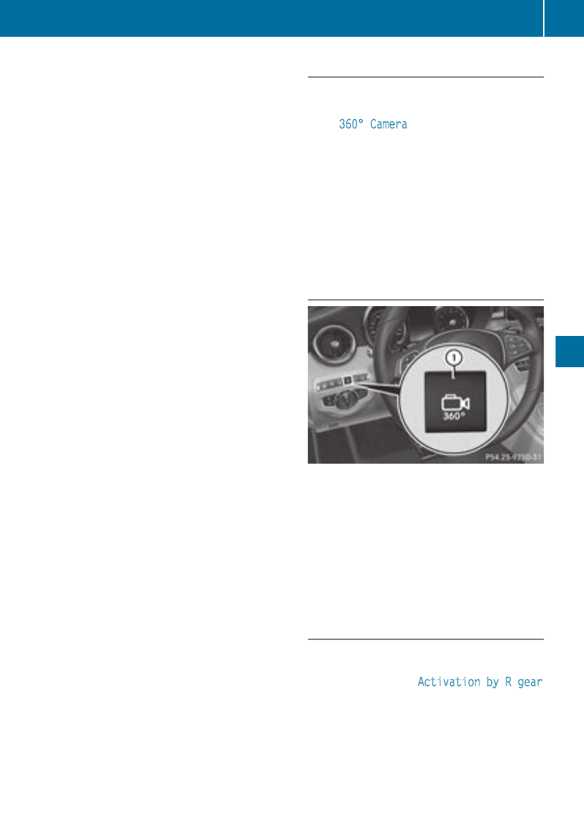
persons, animals or objects in the maneuvering
area while maneuvering and parking in parking
spaces.
You are always responsible for safety, and must
always pay attention to your surroundings when
parking and maneuvering. This applies to the
areas behind, in front of and beside the vehicle.
You could otherwise endanger yourself and oth-
ers.
The 360° camera will not function or will func-
tion in a limited manner:
Rif the doors are open
Rif the exterior mirrors are folded in
Rif the trunk lid is open
Rin heavy rain, snow or fog
Rat night or in very dark places
Rif the cameras are exposed to very bright light
Rif the area is lit by fluorescent bulbs or LED
lighting (the display may flicker)
Rif the camera lenses fog up, e.g. when driving
into a heated garage in winter, causing a rapid
change in temperature
Rif the camera lenses are dirty or covered
Rif the vehicle components in which the cam-
eras are installed are damaged. In this case,
have the camera position and setting checked
at a qualified specialist workshop
Do not use the 360° camera in this case. You
can otherwise injure others or cause damage to
objects or the vehicle.
The guide lines in the multimedia system display
show the distances to your vehicle. The distan-
ces only apply to road level.
The camera in the rear area is protected by
means of a flap. This flap opens when the 360°
camera is activated. Observe the notes on
cleaning (Ypage 309). For technical reasons,
the flap may remain open briefly after the 360°
camera has been deactivated.
The field of vision and other functions of the
camera system may be restricted due to addi-
tional attachments (e.g. license plate holder,
rear bicycle carrier).
On vehicles with height-adjustable chassis,
depending on technical conditions, leaving the
standard height can result in:
Rinaccuracies in the guide lines
Rinaccuracies in the display of generated
images (top view)
Activation conditions
The image from the 360° camera appears if:
Rthe multimedia system is switched on
Rthe 360° Camera function is switched on
If you are driving faster than at a moderate
speed and you turn on the 360° camera, a warn-
ing message appears.
The warning message disappears if:
Ryou are again driving at a moderate speed The
360° camera is then activated
Rthe message is confirmed with the %but-
ton
Switching the 360° camera on and off
using the button
XTo switch on: press button :.
The following appears depending on whether
gear hor kis selected:
Ra split screen with top view and the image
from the front camera or
Ra split screen with top view and the image
from the rear view camera
XTo switch off: press button :.
Activating the 360° camera using
reverse gear
The 360° camera images can be automatically
displayed by engaging reverse gear.
XMake sure that the Activation by R gear
function is selected in the multimedia system
(see the Digital Operator's Manual).
XTo show the 360° camera image: engage
reverse gear.
The multimedia system shows the area
behind the vehicle in split-screen mode. You
Driving systems 193
Driving and parking
Z

see the top view of the vehicle and the image
from the rear view camera.
You cannot stop the 360° camera display if
reverse gear is engaged.
Selecting the split-screen view or full
screen mode
Switching between split screen views:
XTo switch to the line with the vehicle icons:
slide 5the controller.
XTo select a vehicle icon: turn the controller.
Switching to full screen mode:
XTurn and press 180° View with the controller.
The full screen option is only available in the fol-
lowing views:
RTop view with picture from the rear view cam-
era
RTop view with picture from the front camera
Multimedia display
Important safety notes
The camera system may show a distorted view
of obstacles, show them incorrectly or not at all.
Obstacles are not shown by the system in the
following locations:
Runder the front and rear bumpers
Rvery close to the front and rear bumpers
Rin close range above the handle on the trunk
lid
Rvery close to the exterior mirrors
Rin the transitional areas between the various
cameras in the virtual top view
!Objects not at ground level may appear to
be further away than they actually are, e.g.:
Rthe bumper of a parked vehicle
Rthe drawbar of a trailer
Rthe ball coupling of a trailer tow hitch
Rthe rear section of an HGV
Ra slanted post
Use the guidelines only for orientation.
Approach objects no further than the bottom-
most guideline.
Top view with picture from the rear view
camera
:Yellow guide line at a distance of approx-
imately 13 ft (4.0 m) from the rear of the
vehicle
;Symbol for the split screen setting with top
view and rear view camera image
=Guide lines for the maximum steering input
?Yellow lanes marking the course the tires
will take at the current steering wheel angle
(dynamic)
AYellow guide lines for vehicle width including
the exterior mirrors – dynamic for current
steering input
BVehicle center axis (locating aids)
CYellow guide line at a distance of approx-
imately 3 ft (1.0 m) from the rear of the vehi-
cle
DBumper
ERed guide line at a distance of approximately
12 in (0.30 m) from the rear of the vehicle
If the transmission is shifted to position k,
guide lines appear in the camera image.
The distance specifications only apply to
objects that are at ground level.
194 Driving systems
Driving and parking

Top view with picture from the front cam-
era
:Symbol for the split screen setting with top
view and front camera image
;Yellow guide line at a distance of approx-
imately 13 ft (4.0 m) from the front of the
vehicle
=Yellow guide lines for vehicle width including
the exterior mirrors, for current steering
input (dynamic)
?Yellow lanes marking the course the tires
will take at the current steering wheel angle
(dynamic)
ARed guide line at a distance of approximately
12 in (0.30 m) from the front of the vehicle
BYellow guide line at a distance of approx-
imately 3 ft (1.0 m) from the front of the
vehicle
Top view and enlarged rear view
:Symbol for the split screen setting with top
view and rear view camera image enlarged
;Red guide line at a distance of approximately
12 in (0.30 m) from the rear of the vehicle
This view assists you in estimating the distance
to the vehicle behind you.
iThis setting can also be selected as an
enlarged front view.
Top view with image from the side cam-
eras
:Symbol for the top view and forward-facing
side camera setting
;Yellow guide line for the vehicle width
including the exterior mirrors (right side of
vehicle)
=Yellow guide line for the vehicle width
including the exterior mirrors (left side of
vehicle)
iYou can also select the side camera setting
for the rear-facing view.
180° view
:Symbol for the full screen setting with rear
view camera image
;Own vehicle
=PARKTRONIC warning displays
i180° view can also be selected as front
view.
Select this view when you are driving out of an
exit and the view of crossing traffic is restricted,
for example.
If you select the %symbol in the display and
confirm with the controller, the split-screen view
appears.
Driving systems 195
Driving and parking
Z

Exiting 360° camera display mode
XShift the transmission to position j.
or
XDrive forwards at a speed greater than 6 mph
(10 km/h).
The 360° camera display is stopped.
The view that was active before the 360°
camera was displayed appears in the multi-
media system display. You can also stop the
360° camera display split-screen view by
selecting the %symbol in the display and
then confirming with the COMAND controller.
You cannot stop the 360° camera display if
the transmission position kis selected.
ATTENTION ASSIST
General notes
ATTENTION ASSIST helps you during long,
monotonous journeys, such as on highways. It is
active in the 37 mph (60 km/h) to 124 mph
(200 km/h) speed range. If ATTENTION ASSIST
detects typical indicators of fatigue or increas-
ing lapses in concentration on the part of the
driver, it suggests taking a break.
Important safety notes
ATTENTION ASSIST is only an aid to the driver. It
might not always recognize fatigue or increasing
inattentiveness in time or fail to recognize them
at all. The system is not a substitute for a well-
rested and attentive driver.
The functionality of ATTENTION ASSIST is
restricted and warnings may be delayed or not
occur at all:
Rif the length of the journey is less than approx-
imately 30 minutes
Rif the road condition is poor, e.g. if the surface
is uneven or if there are potholes
Rif there is a strong side wind
Rif you have adopted a sporty driving style with
high cornering speeds or high rates of accel-
eration
Rif you are predominantly driving at a speed
below 37 mph (60 km/h) or above 124 mph
(200 km/h)
Rif you are driving with DISTRONIC PLUS Steer-
ing Assist activated
Rif the time has been set incorrectly
Rin active driving situations, such as when you
change lanes or change your speed
The ATTENTION ASSIST tiredness assessment
is deleted and restarted when continuing the
journey, if:
Ryou switch off the engine
Ryou take off your seat belt and open the driv-
er's door, e.g. for a change of drivers or to
take a break
Displaying the attention level
In the Assistance menu (Ypage 219) of the on-
board computer, you can call up the current sta-
tus information.
XSelect the Assistance display for ATTENTION
ASSIST using the on-board computer
(Ypage 218).
The following information appears:
Rthe length of the journey since the last break.
Rthe attention level determined by ATTENTION
ASSIST (Attention Level), displayed in a
bar display in five levels from high to low.
Rif ATTENTION ASSIST is unable to calculate
the attention level and cannot issue a warn-
ing, the System Suspended message
appears. The bar display then changes the
display, e.g. if you are driving at a speed below
37 mph (60 km/h) or above 124 mph
(200 km/h).
Activating ATTENTION ASSIST
XActivate ATTENTION ASSIST using the on-
board computer (Ypage 220).
The system determines the attention level of
the driver depending on the setting selected:
196 Driving systems
Driving and parking

Selection Standard: the sensitivity with which
the system determines the attention level is set
to normal.
Selection Sensitive: the sensitivity is set
higher. The attention level detected by Attention
Assist is adapted accordingly and the driver is
warned earlier.
When ATTENTION ASSIST is deactivated, the
ésymbol appears in the multifunction dis-
play in the assistance graphic display.
When ATTENTION ASSIST has been deactivated,
it is automatically reactivated after the engine
has been stopped. The sensitivity selected cor-
responds to the last selection activated (stand-
ard/sensitive).
Warning in the multifunction display
If fatigue or increasing lapses in concentration
are detected, a warning appears in the multi-
function display: ATTENTION ASSIST Take a
Break!.
In addition to the message shown in the multi-
function display, you will then hear a warning
tone.
XIf necessary, take a break.
XConfirm the message by pressing the a
button on the steering wheel.
On long journeys, take regular breaks in good
time to allow yourself to rest properly. If you do
not take a break and ATTENTION ASSIST con-
tinues to detect increasing lapses in concentra-
tion, you will be warned again after 15 minutes
at the earliest. This will only happen if ATTEN-
TION ASSIST still detects typical indicators of
fatigue or increasing lapses in concentration.
Vehicles with COMAND multimedia system:
if a warning appears in the multifunction display,
a service station search is performed in the mul-
timedia system. You can select a service station
and navigation to this service station will then
begin. This function can be activated and deac-
tivated in the COMAND multimedia system (see
the Digital Operator's Manual).
Traffic Sign Assist
General notes
Traffic Sign Assist displays the maximum speed
permitted to the driver in the instrument cluster.
The data and general traffic regulations stored in
the navigation system are used to determine the
current speed limit.
Traffic Sign Assist is a map-based system, and
for this reason, traffic signs put up temporarily
(e.g. near roadworks) are not detected. There is
also no display for changing traffic signs.
Traffic signs with a restriction indicated by an
additional sign (e.g. in wet conditions) are also
shown.
The sign indicating the end of a restriction only
appears with the restriction in the instrument
cluster when:
RThe regulation must be observed with the
restriction, or
RTraffic Sign Assist is unable to determine
whether the restriction applies
If Traffic Sign Assist is unable to determine a
maximum permitted speed from any of the avail-
able sources, no speed limit appears in the
instrument cluster either.
Traffic Sign Assist is not available in all coun-
tries. In this case, display :appears in the
assistance graphic (Ypage 218).
Important safety notes
Traffic Sign Assist is only an aid and is not always
able to correctly display speed limits. Traffic
signs always have priority over the Traffic Sign
Assist display.
The system may be either functionally impaired
or temporarily unavailable if the information in
the digital street map of the navigation system is
incorrect or out of date.
Driving systems 197
Driving and parking
Z

Instrument cluster display
Displaying the assistance graphic
XCall up theassistancegraphic display func-
tion usingtheon-board computer
(Ypage 218).
Detected traffic signsappear in theinstru-
mentcluster.
Speed limit with unknown restriction
:Maximum permittedspeed
;Maximum permittedspeedfor vehicles for
whichtherestriction in theadditional sign is
relevant
=Additional sign for unknown restriction
Amaximum permittedspeedof 80 mph
(80 km/h) and aspeedlimitof 60 mph
(60 km/h) withan unknown restriction apply.
The unit for thespeedlimit(km/hor mph)
dependson thecountry in whichyou are driving.
It is generally neither shown on thetraffic sign
noron theinstrumentclusterbut must be taken
intoaccountwhen observing themaximum per-
mittedspeed.
Lane Tracking package
General notes
The LaneTrackingpackageconsistsof Blind
Spot Assist (Ypage 198) and LaneKeeping
Assist (Ypage 200).
Blind Spot Assist
General notes
Blind Spot Assist monitors theareas on either
side of thevehiclethat are notvisible to the
driver withtwo lateral,rear-facingradar sen-
sors. Awarning lamp lights up in theexterior
mirrorsand draws your attention to vehicles
detectedin themonitoredarea. If you then
switch on thecorresponding turnsignal to
changelane, you will also receivean optical and
audible warning.
Blind Spot Assist supportsyou from aspeedof
approximately 20 mph (30 km/h).
Important safety notes
GWARNING
Blind Spot Assist does notreactto:
Rvehicles overtakentooclosely on theside,
placing them in theblindspotarea
Rvehicles whichapproachwith a largespeed
differential and overtake your vehicle
As aresult,Blind Spot Assist may notgive
warningsin suchsituations. Thereis ariskof
an accident.
Always observethetraffic conditionscare-
fully, and maintain a safelateral distance.
Blind Spot Assist is only an aid. It may fail to
detectsomevehicles and is no substitutefor
attentive driving.Always ensurethat there is
sufficientdistanceto theside for other road
usersand obstacles.
iUSAonly:
This device has been approvedby theFCC as
a"Vehicular Radar System". The radar sensor
is intended for use in an automotive radar
system only. Removing, tampering with, or
altering thedevice will voidany warranties,
and is notpermittedby theFCC. Do nottam-
per with, alter, or use in any non-approved
way.
Anyunauthorized modification to this device
could voidtheuser’s authority to operate the
equipment.
Radar sensors
The radar sensorsfor Blind Spot Assist are inte-
grated intotherear bumper. Makesurethat the
bumpers are free from dirt,ice or slush. The
sensorsmust notbe covered, for exampleby
cycle racks or overhanging loads.Following a
severe impact or in theevent of damageto the
bumpers,havethefunction of theradar sensors
checkedat aqualified specialist workshop.
Blind Spot Assist may no longer workproperly.
198 Driving systems
Driving and parking

Monitoring area
In particular, the detection of obstacles can be
impaired if:
Rthere is dirt on the sensors or anything else
covering the sensors
Rthere is poor visibility, e.g. due to fog, heavy
rain, snow or spray
Rthere are narrow vehicles, e.g. motorcycles or
bicycles
Rthe road has very wide lanes
Rthe road has narrow lanes
Ryou are not driving in the middle of the lane
Rthere are barriers or other road boundaries
Vehicles in the monitoring range are then not
indicated.
At a distance of around 1.6 ft (0.5 m) ;from the
vehicle, Blind Spot Assist monitors the area up
to 10 ft (3 m) next to =and behind :your
vehicle, as shown in the picture.
If the lanes are narrow, vehicles driving in the
lane beyond the lane next to your vehicle may be
indicated, especially if the vehicles are not driv-
ing in the middle of their lane. This may be the
case if there are vehicles driving at the inner
edge of their lanes.
Due to the nature of the system:
Rwarnings may be issued in error when driving
close to crash barriers or similar solid lane
borders
Rwarnings may be interrupted when driving
alongside long vehicles, such as trucks, for a
prolonged time
Warning lamp
:Warning lamp
Blind Spot Assist is not active at speeds below
approximately 20 mph (30 km/h). Vehicles in
the monitoring range are then not indicated.
If a vehicle is detected within the blind spot
monitoring range at speeds above 20 mph
(30 km/h), warning lamp :on the correspond-
ing side lights up red. This warning is always
emitted when a vehicle enters the blind spot
monitoring range from behind or from the side.
When you overtake a vehicle, the warning only
occurs if the difference in speed is less than
7 mph (12 km/h).
If you select the reverse gear, Blind Spot Assist
is not operational.
The brightness of the warning lamps is auto-
matically adapted to the brightness of the sur-
roundings.
Collision warning
If a vehicle is detected in the monitoring range of
Blind Spot Assist and you switch on the corre-
sponding turn signal, a double warning tone
sounds. The red warning lamp flashes on the
relevant exterior mirror. If the turn signal
remains on, detected vehicles are indicated by
the flashing of the red warning lamp on the exte-
rior mirror. There are no further warning tones.
Switching on Blind Spot Assist
XMake sure that Blind Spot Assist is activated
in the on-board computer (Ypage 220).
XTurn the SmartKey to position 2in the igni-
tion lock.
The red warning lamps on the exterior mirrors
light up until the engine is started.
Driving systems 199
Driving and parking
Z

Display in theassistancegraphic
WhenBlind Spot Assistis activated, grayradar
wavespropagatingbackwards appear next to
thevehiclein theassistancedisplay in themul-
tifunction display (Ypage 218). Above aspeed
of 20 mph (30 km/h), thecolor of theradar
wavesin theassistancegraphic changes to
green :.Blind Spot Assistis then ready foruse.
LaneKeeping Assist
General notes
LaneKeepingAssistmonitors theareain frontof
your vehicleby means of multifunction cam-
era :whichis attached behindthetopof the
windshield.Active LaneKeepingAssistdetects
lanemarkingson theroadand can warn you
before you leaveyour laneunintentionally.
This function is available in therange between
40 mph and 120mph (60 km/hand 200 km/h).
A warning may be given if a front wheel passes
over a lane marking. It will warn you by means of
intermittent vibration in the steering wheel for
up to 1.5 seconds.
Important safety notes
GWARNING
Lane Keeping Assist may not always clearly
recognize lane markings.
In this case, Lane Keeping Assist may:
Rgive an unnecessary warning
Rnot give a warning
There is a risk of an accident.
Always pay particular attention to the traffic
situation and stay in lane, in particular if
warned by Lane Keeping Assist.
GWARNING
The Lane Keeping Assist warning does not
return the vehicle to the original lane. There is
a risk of an accident.
You should always steer, brake or accelerate
yourself, in particular if warned by Lane Keep-
ing Assist.
Lane Keeping Assist can neither reduce the risk
of an accident if you fail to adapt your driving
style nor override the laws of physics. Lane
Keeping Assist cannot take into account the
road, traffic and weather conditions. Lane Keep-
ing Assist is merely an aid. You are responsible
for the distance to the vehicle in front, for vehi-
cle speed, for braking in good time and for stay-
ing in your lane.
The Lane Keeping Assist does not keep the vehi-
cle in the lane.
The system may be impaired or may not function
if:
Rthere is poor visibility, e.g. due to insufficient
illumination of the road, or due to snow, rain,
fog or spray
Rthere is glare, e.g. from oncoming traffic, the
sun or reflection from other vehicles (e.g. if
the road surface is wet)
Rthe windshield is dirty, fogged up, damaged or
covered, for instance by a sticker, in the vicin-
ity of the camera
Rthere are no, several or unclear lane markings
for a lane, e.g. in areas with road construction
work
Rthe lane markings are worn away, dark or cov-
ered up, e.g. by dirt or snow
200 Driving systems
Driving and parking

Rthe distance to the vehicle in front is too small
and the lane markings thus cannot be detec-
ted
Rthe lane markings change quickly, e.g. lanes
branch off, cross one another or merge
Rthe road is narrow and winding
Rthere are highly variable shade conditions on
the roadway
Activating/deactivating Lane Keeping
Assist
XTo activate: press button ;.
Indicator lamp :lights up. The Lane Keep‐
ing Assist On message appears in the mul-
tifunction display. If all conditions have been
satisfied, there may be a warning.
If you drive at speeds above 40 mph
(60 km/h) and lane markings are detected,
the lines in the assistance graphics display
(Ypage 218) are shown in green. Lane Keep-
ing Assist is ready for use.
XTo deactivate: press button ;.
Indicator lamp :goes out. Lane Keeping
Assist is deactivated. The Lane Keeping
Assist Off message appears in the multi-
function display.
Selecting Standard or Adaptive setting
XIn the DriveAssist menu on the on-board
computer, select the Lane Keeping Assist
function (Ypage 220).
XSelect Standard or Adaptive.
Standard
When Standard is selected, no warning vibra-
tion occurs if:
Ryou switch on the turn signals. In this event,
the warnings are suppressed for a certain
period of time.
Ra driving safety system intervenes, e.g. ABS,
BAS or ESP®.
Adaptive
When Adaptive is selected, no warning vibra-
tion occurs if:
Ryou switch on the turn signals. In this event,
the warnings are suppressed for a certain
period of time.
Ra driving safety system intervenes, e.g. ABS,
BAS or ESP®.
Ryou accelerate hard, e.g. kickdown.
Ryou brake hard.
Ryou steer actively, e.g. swerve to avoid an
obstacle or change lanes quickly.
Ryou cut the corner on a sharp bend.
In order that you are warned only when neces-
sary and in good time if you cross the lane mark-
ing, the system recognizes certain conditions
and warns you accordingly.
The warning vibration occurs earlier if:
Ryou approach the outer lane marking on a
bend.
Rthe road has very wide lanes, e.g. a highway.
Rthe system detects solid lane markings.
The warning vibration occurs later if:
Rthe road has narrow lanes.
Ryou cut the corner on a bend.
Driving Assistance PLUS package
General notes
The Driving Assistance PLUS package consists
of DISTRONIC PLUS (Ypage 169), Active Blind
Spot Assist (Ypage 201)and Active Lane Keep-
ing Assist (Ypage 204).
Active Blind Spot Assist
General notes
Active Blind Spot Assist uses a radar sensor
system, pointed toward the rear of the vehicle,
to monitor the area to the sides of the vehicle
which the driver is unable to see. A warning lamp
lights up in the exterior mirrors and draws your
attention to vehicles detected in the monitored
Driving systems 201
Driving and parking
Z

area. If you then switch on the corresponding
turn signal to change lane, you will also receive
an optical and audible warning. If a risk of lateral
collision is detected, corrective braking may
help you avoid a collision. Before a course-cor-
recting brake application, Active Blind Spot
Assist evaluates the space in the direction of
travel and at the sides of the vehicle. For this,
Active Blind Spot Assist uses the forward-facing
radar sensors.
Active Blind Spot Assist supports you from a
speed of approximately 20 mph (30 km/h).
Important safety notes
Active Blind Spot Assist is only an aid and is not
a substitute for attentive driving.
GWARNING
Active Blind Spot Assist does not react to:
Rvehicles overtaken too closely on the side,
placing them in the blind spot area
Rvehicles which approach with a large speed
differential and overtake your vehicle
As a result, Active Blind Spot Assist may nei-
ther give warnings nor intervene in such sit-
uations. There is a risk of an accident.
Always observe the traffic conditions care-
fully, and maintain a safe lateral distance.
iUSA only: This device has been approved by
the FCC as a "Vehicular Radar System". The
radar sensor is intended for use in an auto-
motive radar system only. Removal, tamper-
ing, or altering of the device will void any war-
ranties, and is not permitted by the FCC. Do
not tamper with, alter, or use in any non-
approved way.
Any unauthorized modification to this device
could void the user's authority to operate the
equipment.
iCanada only: This device complies with
RSS-210 of Industry Canada. Operation is
subject to the following two conditions:
1. This device may not cause interference,
and
2. This device must accept any interference
received, including interference that may
cause undesired operation of the device.
Removal, tampering, or altering of the device
will void any warranties, and is not permitted.
Do not tamper with, alter, or use in any non-
approved way.
Any unauthorized modification to this device
could void the user's authority to operate the
equipment.
Radar sensors
The Active Blind Spot Assist radar sensors are
integrated into the front and rear bumpers and
behind a cover in the radiator trim. Make sure
that the bumpers and the cover in the radiator
grill are free of dirt, ice or slush. The rear sensors
must not be covered, for example by cycle racks
or overhanging cargo. Following a severe impact
or in the event of damage to the bumpers, have
the function of the radar sensors checked at a
qualified specialist workshop. Active Blind Spot
Assist may otherwise no longer work properly.
Monitoring area
GWARNING
Active Blind Spot Assist does not detect all
traffic situations and road users. There is a
risk of an accident.
Always make sure that there is sufficient dis-
tance on the side for other traffic or obstacles.
At a distance of approximately 1.6 ft (0.5 m) ;
from the vehicle, Active Blind Spot Assist mon-
itors the area up to 10 ft (3 m) next to =and
behind :your vehicle, as shown in the picture.
202 Driving systems
Driving and parking

The detection of obstacles can be impaired in
the case of:
Rthere is dirt on the sensors or anything else
covering the sensors
Rpoor visibility, e.g. due to rain, snow or spray
Vehicles in the monitoring range are then not
indicated.
Active Blind Spot Assist may not detect narrow
vehicles, such as motorcycles or bicycles, or
may only detect them too late.
If the lanes are narrow, vehicles driving in the
lane beyond the lane next to your vehicle may be
indicated, especially if the vehicles are not driv-
ing in the middle of their lane. This may be the
case if there are vehicles at the inner edge of
your lane.
Due to the nature of the system:
Rwarnings may be issued in error when driving
close to crash barriers or similar solid lane
borders.
Rwarnings may be interrupted when you are
driving alongside particularly long vehicles,
such as trucks, for a prolonged time.
Warning lamp
:Warning lamp
Active Blind Spot Assist is not operational at
speeds below approximately 20 mph (30 km/h).
Vehicles in the monitoring range are then not
indicated.
If a vehicle is detected within the blind spot
monitoring range at speeds above 20 mph
(30 km/h), warning lamp :on the correspond-
ing side lights up red. This warning is always
emitted when a vehicle enters the blind spot
monitoring range from behind or from the side.
When you overtake a vehicle, the warning only
occurs if the difference in speed is less than
7 mph (12 km/h).
If you select the reverse gear, Active Blind Spot
Assist is not operational.
The brightness of the warning lamps is auto-
matically adapted to the brightness of the sur-
roundings.
When Active Blind Spot Assist is activated, gray
radar waves propagating backward appear next
to the vehicle in the assistance display in the
multifunction display. Above a speed of 20 mph
(30 km/h), the color of the radar waves in the
assistance display changes to green ;. Active
Blind Spot Assist is then ready for use.
Visual and acoustic collision warning
If you switch on the turn signals to change lanes
and a vehicle is detected in the side monitoring
range, you receive a visual and acoustic collision
warning. You will then hear a double warning
tone and red warning lamp :flashes. If the turn
signal remains on, detected vehicles are indica-
ted by the flashing of red warning lamp :.
There are no further warning tones.
Course-correcting brake application
If Active Blind Spot Assist detects a risk of a lat-
eral collision in the monitoring range, a course-
correcting brake application is carried out. This
is meant to assist you in avoiding a collision.
GWARNING
A course-correcting brake application cannot
always prevent a collision. There is a risk of an
accident.
Always steer, brake or accelerate yourself,
especially if Active Blind Spot Assist warns
you or makes a course-correcting brake appli-
cation. Always maintain a safe distance at the
sides.
Driving systems 203
Driving and parking
Z

If a course-correcting brake application occurs,
red warning lamp :flashes in the exterior mir-
ror and a double warning tone sounds. In addi-
tion, a display underlining the danger of a side
collision appears in the multifunction display.
In very rare cases, the system may make an
inappropriate brake application. A course-cor-
recting brake application may be interrupted at
any time by countersteering slightly or acceler-
ating.
The course-correcting brake application is avail-
able in the speed range between 20 mph
(30 km/h) and 120 mph (200 km/h).
Either no braking application, or a course-cor-
recting brake application adapted to the driving
situation occurs if:
Rthere are vehicles or obstacles, e.g. crash
barriers, located on both sides of your vehicle.
Ra vehicle approaches you too closely at the
side.
Ryou have adopted a sporty driving style with
high cornering speeds.
Ryou clearly brake or accelerate.
Ra driving safety system intervenes, e.g. ESP®
or PRE-SAFE®Brake.
RESP®is switched off.
Ra loss of tire pressure or a defective tire is
detected.
Switching on Active Blind Spot Assist
XMake sure that Active Blind Spot Assist is
activated in the on-board computer
(Ypage 220).
XSwitch on the ignition.
Warning lamps :in the exterior mirrors light
up red for approximately 1.5 seconds.
Gray radar waves propagating backwards
appear next to the vehicle in the assistance
graphic in the multifunction display ;.
Above a speed of 20 mph (30 km/h), the color
of the radar waves in the assistance display
changes to green ;. Active Blind Spot Assist
is then ready for use.
Active Lane Keeping Assist
General notes
Active Lane Keeping Assist monitors the area in
front of your vehicle by means of multifunction
camera :at the top of the windshield. Various
different areas to the front, rear and side of your
vehicle are also monitored with the aid of the
radar sensor system. Active Lane Keeping
Assist detects lane markings on the road and
can warn you before you leave your lane unin-
tentionally. If you do not react to the warning, a
lane-correcting application of the brakes can
bring the vehicle back into the original lane.
This function is available in the range between
40 mph and 120 mph (60 km/h and 200 km/h).
Important safety notes
If you fail to adapt your driving style, Active Lane
Keeping Assist can neither reduce the risk of an
accident nor override the laws of physics. Active
Lane Keeping Assist cannot take account of
road and weather conditions. It may not recog-
nize traffic situations. Active Lane Keeping
Assist is only an aid. You are responsible for the
distance to the vehicle in front, for vehicle
speed, for braking in good time and for staying in
your lane.
Active Lane Keeping Assist cannot continuously
keep your vehicle in its lane.
GWARNING
Active Lane Keeping Assist cannot always
clearly detect lane markings.
204 Driving systems
Driving and parking

In such cases, Active Lane Keeping Assist
can:
Rgive an unnecessary warning and then
make a course-correcting brake application
to the vehicle
Rnot give a warning or intervene
There is a risk of an accident.
Always pay particular attention to the traffic
situation and keep within the lane, especially
if Active Lane Keeping Assist alerts you. Ter-
minate the intervention in a non-critical driv-
ing situation.
The system may be impaired or may not function
if:
Rthere is poor visibility, e.g. due to insufficient
illumination of the road, or due to snow, rain,
fog or spray
Rthere is glare, e.g. from oncoming traffic, the
sun or reflection from other vehicles (e.g. if
the road surface is wet)
Rthe windshield is dirty, fogged up, damaged or
covered, for instance by a sticker, in the vicin-
ity of the camera
Rthe radar sensors in the front or rear bumpers
or the radiator trim are dirty, e.g. obscured by
snow
Rthere are no, several or unclear lane markings
for a lane, e.g. in areas with road construction
work
Rthe lane markings are worn away, dark or cov-
ered up, e.g. by dirt or snow
Rthe distance to the vehicle in front is too small
and the lane markings thus cannot be detec-
ted
Rthe lane markings change quickly, e.g. lanes
branch off, cross one another or merge
Rthe road is narrow and winding
Rthere are highly variable shade conditions on
the roadway
If no vehicle is detected in the adjacent lane and
broken lane markings are detected, no lane-cor-
recting brake application is made.
Warning vibration in the steering wheel
A warning may be given if a front wheel passes
over a lane marking. It will warn you by means of
intermittent vibration in the steering wheel for
up to 1.5 seconds.
Lane-correcting brake application
If you leave your lane, under certain circumstan-
ces the vehicle will brake briefly on one side.
This is meant to assist you in bringing the vehicle
back to the original lane.
GWARNING
A lane-correcting brake application cannot
always bring the vehicle back into the original
lane. There is a risk of an accident.
Always steer, brake or accelerate yourself,
especially if Active Lane Keeping Assist warns
you or makes a lane-correcting brake appli-
cation.
If a lane-correcting brake application occurs,
display :appears in the multifunction display.
The brake application also slightly reduces vehi-
cle speed.
A lane-correcting brake application can be made
after driving over a lane marking detected as
being solid or broken. Before this, a warning
must be given by means of intermittent vibration
in the steering wheel. In addition, a lane with
lane markings on both sides must be recog-
nized.
In the case of a broken lane marking being
detected, a lane-correcting brake application
can only be made if a vehicle has been detected
in the adjacent lane. Oncoming vehicles, over-
taking vehicles and vehicles in adjacent lanes
can be detected.
A further lane-correcting brake application can
only occur after your vehicle has returned to the
original lane.
No lane-correcting brake application occurs if:
Ryou clearly and actively steer, brake or accel-
erate.
Ryou cut the corner on a sharp bend.
Driving systems 205
Driving and parking
Z

Ryou haveswitched on theturnsignal.
Radrivingsafetysystem intervenes, e.g. ESP®,
PRE-SAFE®Brake or Active Blind Spot Assist.
Ryou haveadopted a sportydrivingstyle with
high cornering speeds or high rates of accel-
eration.
RESP®is switched off.
Rthetransmission is notin position h.
Raloss of tire pressureor adefective tire has
been detectedand displayed.
Ran obstacle has been detectedin thelanein
whichyou are driving.
Active LaneKeepingAssistmay notdetectother
roadusersor traffic situations. An inappropriate
brakeapplication may be interrupted at any time
if you:
Rsteer slightly in theoppositedirection.
Rswitch on theturnsignal.
Ryou brakeor accelerate significantly.
Alane-correcting brakeapplication is interrup-
tedautomatically if:
Radrivingsafetysystem intervenes, e.g. ESP®,
PRE-SAFE®Brake or Active Blind Spot Assist.
Rlanemarkingsare no longer detected.
Activating/deactivating Active Lane
Keeping Assist
XTo activate: press button;.
Indicatorlamp :lights up. The LaneKeep‐
ing Assist On message appears on the
multifunction display. If all conditionshave
been satisfied, awarningor steeringinter-
vention may be made.
If you drive at speeds above40 mph
(60 km/h) and lanemarkingsare detected,
thelines in theassistancegraphic
(Ypage 218) appearin green.Active Lane
KeepingAssistis readyfor use.
XTo deactivate: press button;.
Indicatorlamp :goesout.The Active Lane
KeepingAssistis deactivated. The Lane
KeepingAssist Off message appears on
themultifunction display.
Selecting Standardor Adaptive setting
XIn theDriveAssist menuon theon-board
computer, select theActive LaneKeep‐
ing Assist function (Ypage 220).
XSelectsetting Standard or Adaptive.
WhenStandard is selected, no warningvibra-
tion occursif:
Ryou switch on theturnsignals. In this event,
thewarnings are suppressed for acertain
period of time.
Radrivingsafetysystem intervenes, suchas
ABS, BASor ESP®.
WhenAdaptive is selected, no warningvibra-
tion occursif:
Ryou switch on theturnsignals. In this event,
thewarnings are suppressed for acertain
period of time.
Radrivingsafetysystem intervenes, e.g.
ABS, BASor ESP®.
Ryou accelerate hard, e.g. kickdown.
Ryou brakehard.
Ryou steer actively, e.g. swerve to avoid an
obstacle or changelanes quickly.
Ryou cut thecorner on asharpbend.
In order that you are warned only when neces-
saryand in goodtime if you cross thelanemark-
ing, thesystem recognizes certain conditions
and warnsyou accordingly.
The warningvibration occursearlier if:
Ryou approachtheouter lanemarking on a
bend.
Rtheroadhas verywide lanes, e.g. ahighway.
Rthesystem detects solidlanemarkings.
The warningvibration occurslater if:
Rtheroadhas narrow lanes.
Ryou cut thecorner on abend.
206 Driving systems
Driving and parking

Important safety notes
GWARNING
If you operate information systems and com-
munication equipmentintegratedin thevehi-
cle while driving,you will be distractedfrom
traffic conditions. You could also lose control
of thevehicle. Thereis ariskof an accident.
Only operate theequipmentwhen thetraffic
situation permits. If you are notsurethat this
is possible,park thevehiclepayingattention
to traffic conditionsand operate theequip-
mentwhen thevehicleis stationary.
You must observethelegal requirements for the
country in whichyou are currentlydriving when
operating theon-board computer.
GWARNING
If theinstrumentclusterhas failedor mal-
functioned, you may notrecognize function
restrictionsin systems relevantto safety. The
operating safetyof your vehiclemay be
impaired.Thereis ariskof an accident.
Drive on carefully. Havethevehiclechecked
at aqualified specialist workshop immedi-
ately.
If theoperating safetyof your vehicleis
impaired,pull overas soonas it is safeto do so.
Contact a qualified specialist workshop.
The on-board computer only shows messagesor
warningsfrom certain systems in themultifunc-
tion display. You should thereforemakesure
your vehicleis operating safely at all times.
Foran overview, see theinstrumentpanel illus-
tration (Ypage 36).
Hybrid vehicles: makesurethat you read the
separateoperating instructions. Otherwise, you
may notrecognize dangers.
Displays and operation
Instrument cluster lighting
The lighting in theinstrumentcluster, in thedis-
plays and thecontrolsin thevehicleinterior can
be adjusted usingbrightness control knob :.
XTurn brightness control knob :up or down.
If you turnthelightswitch (Ypage 113) to the
T,Ãor Lposition,thebrightness
will depend upon thebrightness of theambi-
entlight.
iThe lightsensor in theinstrumentcluster
automatically controlsthebrightness of the
multifunction display.
In daylight, thedisplays in theinstrument
clusterare illuminated. Adimming function is
notpossiblein daylight.
Speedometer with segments
The speedometer is divided intosegments
depending on theequipment.
The segments in thespeedometer indicate
whichspeedrange is available.
RCruisecontrol activated (Ypage 167):
The segments lightup from thestoredspeed
to theendof thescale.
RDISTRONICPLUSactivated (Ypage 169):
Oneor two segments in theset speedrange
lightup.
RDISTRONICPLUSdetects avehiclein front
moving moreslowly than thestoredspeed:
The segments between thespeedof thevehi-
cle in frontand thestoredspeedlightup.
Displays and operation 207
On-board computer and displays
Z

Tachometer
!Do not drive in the overrevving range, as this
could damage the engine.
The red band in the tachometer indicates the
engine's overrevving range.
The fuel supply is interrupted to protect the
engine when the red band is reached.
Outside temperature display
You should pay special attention to road condi-
tions when temperatures are around freezing
point.
Bear in mind that the outside temperature dis-
play indicates the temperature measured and
does not record the road temperature.
The outside temperature display is in the multi-
function display (Ypage 209).
Changes in the outside temperature are dis-
played after a short delay.
Coolant temperature gauge
GWARNING
Opening the hood when the engine is over-
heated or when there is a fire in the engine
compartment could expose you to hot gases
or other service products. There is a risk of
injury.
Let an overheated engine cool down before
opening the hood. If there is a fire in the
engine compartment, keep the hood closed
and contact the fire department.
!A display message is shown if the coolant
temperature is too high.
If the coolant temperature is over 248 ‡
(120 †), do not continue driving. The engine
will otherwise be damaged.
The coolant temperature gauge is in the lower
section of the tachometer (Ypage 36).
Under normal operating conditions and with the
specified coolant level, the coolant temperature
may rise to 248 ‡ (120 †).
Operating the on-board computer
:Multifunction display
;Right control panel
=Left control panel
XTo activate the on-board computer: switch
on the power supply.
You can control the multifunction display and
the settings in the on-board computer using the
buttons on the multifunction steering wheel.
Left control panel
òROpens a menu list
9
:
Press briefly:
RScrolls in lists
RSelects a menu or function
RIn the Radio or Media menu:
opens a track or station list and
selects a station, an audio track or
a video scene.
RIn the Telephone menu: switches
to the phone book and selects a
name or a telephone number
9
:
Press and hold:
RScrolls quickly through all lists
RIn the Radio or Media menu:
selects a station, audio track or
video scene using rapid scrolling
RIn the Telephone menu: starts
rapid scrolling if the phone book is
open
208 Displays andoperation
On-board computer and displays

aRIn all menus: confirms the selected
entry in the list
RIn the Radio or Media menu:
opens the list of available radio
sources or media
RIn the Telephone menu: switches
to the phone book and starts dial-
ing the selected number
ñRVehicles with multimedia system
Audio 20:
Switches off voice-operated con-
trol for navigation (see the manu-
facturer's operating instructions)
RVehicles with multimedia system
COMAND:
Switches off the Voice Control
System (see the separate operat-
ing instructions)
%Press briefly:
RBack
RIn the Radio or Media menu: exits
the track or station list or list of
available radio sources or media
RHides display messages
RExits the phone book/redial mem-
ory
%Press and hold:
RCalls up the standard display in the
Trip menu
Right control panel
~RRejects or ends a call
RExits the phone book/redial mem-
ory
6RMakes or accepts a call
RSwitches to the redial memory
W
X
RAdjusts the volume
8RMute
óRVehicles with multimedia system
Audio 20:
Switches on voice-operated con-
trol for navigation (see the manu-
facturer's operating instructions)
RVehicles with multimedia system
COMAND:
Switches on the Voice Control Sys-
tem (see the separate operating
instructions)
Multifunction display
:Drive program (Ypage 147)
;Transmission position (Ypage 148)
=Additional speedometer
?Display
ATime
BOutside temperature (Ypage 208)
Display panel ?shows the selected menu or
submenu and display messages.
XTo open the menu list: press the òbut-
ton on the steering wheel.
Display panel ?appears in the menu list.
Possible displays in the multifunction dis-
play:
RZGearshift recommendation, when shifting
manually (Ypage 152)
RjActive Parking Assist (Ypage 184)
R¯Cruise control (Ypage 167)
Displays and operation 209
On-board computer and displays
Z

RaDISTRONIC PLUS Steering Assist and
Stop&Go Pilot (Ypage 175)
R_Adaptive Highbeam Assist
(Ypage 115)
RèECO start/stop function (Ypage 140)
RëHOLD function (Ypage 177)
Head-up display
General notes
The head-up display projects information from
the navigation system and the driver assistance
system above the dashboard into the driver's
field of vision. The head-up display allows the
driver to see all of the information without hav-
ing to take their eyes off the road.
A requirement for the display of the contents is
that the following functions are available in the
vehicle and are switched on:
RCruise control
RDISTRONIC PLUS
RTraffic Sign Assist
RNavigation
Important safety notes
The head-up display is only an aid and is not a
substitute for attentive driving.
The visibility of the head-up display is influenced
by the following conditions:
Rthe driver's seat position
Rthe positioning of the display image
Rthe general ambient light
Rsunglasses with polarization filters
Rwet roads
Rblocking of sunlight by objects on the display
cover
In the event of extreme sunlight, sections of the
display may fade. This can be reversed by
switching the head-up display off and on again.
iVehicles with the head-up display are equip-
ped with a special windshield. Should repairs
be necessary, have the windshield replaced at
a qualified specialist workshop.
Displays and operation
Switching the head-up display on/off
XPress button :.
When the head-up display is switched on, the
display appears in the driver's field of vision.
Standard displays in the head-up display
:Navigation messages
;Current speed
=Detected traffic signs
?Cruise control or DISTRONIC PLUS set
speed
210 Displays andoperation
On-board computer and displays

AMG displays in the head-up display
:Protection against reachingtheoverrevving
range
;RACETIMER lap
=RACETIMER lap time
?Currentspeed
ACurrently selected gear,gearshiftoptions
when shiftingmanually
BCurrentenginespeed
Setting options
You can adjust thefollowingsettings in the
head-up display submenu:
Radjust thepositionof thehead-up display on
thewindshield (Ypage 221)
Radjust thebrightness of thedisplays in the
head-up display (Ypage 221)
Rselect desired displays in thehead-up display
(Ypage 220)
UsingtheDisplayContentfunction,you
can,depending on your vehicle's equipment,
choosebetween four standard displays. The
selected contents then appear in thehead-up
display.
In Mercedes-AMGvehicles, you can choose
between further AMGdisplays in addition to
thestandard displays, depending on your
vehicle's equipment.
If you select adisplay withtraffic signs, detec-
tedtraffic signsfrom Traffic SignAssist
appear in thehead-up display.
Menus and submenus
Menu overview
Press theòbuttonon thesteering wheelto
open themenulist.
Operating theon-board computer (Ypage 208).
Dependingon thevehicleequipment, you can
select thefollowingmenu:
RTripmenu (Ypage 211)
RNavimenu(navigation instructions)
(Ypage 213)
RRadio menu (Ypage 215)
RMedia menu (Ypage 215)
RTelephone menu (Ypage 217)
RAssistanceGraphicmenu (Ypage 218)
RServicemenu (Ypage 218)
RSettings menu (Ypage 219)
RAMG menuin Mercedes-AMGvehicles
(Ypage 223)
Trip menu
Standard display
XPress and hold the%buttonon thesteer-
ing wheeluntil theTripmenuwithtrip odom-
eter :and odometer ;appears.
Menus and submenus 211
On-board computer and displays
Z

Displaying therange andcurrent fuel
consumption
:Range of thefuelsupply
;Currentfuelconsumption
=Recuperation display
XPress theòbuttonon thesteeringwheel
to openthemenulist.
XPress :or 9on thesteeringwheelto
selecttheTripmenu.
XConfirmby pressing aon thesteering
wheel.
XPress 9or :to selectthedisplay.
Approximaterange :that can be covered is
calculated accordingto your currentdriving
style and theamount of fuelin thetank.If
there is only asmall amount of fuelleftin the
fueltank, a vehicle beingrefueledC
appears instead of approximaterange :.
Recuperation display =shows you if energy
has beenrecuperated from thekineticenergy
in overrun mode and saved in thebattery.
Recuperation display =dependson the
engineinstalled and is therefore notavailable
in all vehicles.
ECO display
XPress òon thesteeringwheelto openthe
menulist.
XPress :or 9on thesteeringwheelto
selecttheTripmenu.
XConfirmby pressing aon thesteering
wheel.
XPress the:or 9buttonto selectECO
display.
If theignition remainsswitched offforlonger
than four hours, theECOdisplay will be auto-
matically reset.
Forfurther information on theECOdisplay, see
(Ypage 163).
Trip computer"From Start" or "From
Reset"
:Distance
;Driving time
=Average speed
?Average fuelconsumption
XPress theòbuttonon thesteeringwheel
to openthemenulist.
XPress :or 9on thesteeringwheelto
selecttheTripmenu.
XConfirmby pressing aon thesteering
wheel.
XPress :or 9to selectFromStart or
FromReset.
The values in theFromStart submenuare
calculated from thestart of ajourney, while
thevalues in theFromReset submenuare
calculated from thelast time thesubmenu
was reset (Ypage 213).
In thefollowingcases, thetrip computeris
automatically reset FromStart:
Rtheignition has beenswitched offformore
than four hours.
R999hourshavebeenexceeded.
R9,999 miles havebeenexceeded.
When9,999 hoursor 99,999miles havebeen
exceeded, thetrip computeris automatically
reset FromReset.
Digital speedometer
XPress òon thesteeringwheelto openthe
menulist.
XPress :or 9on thesteeringwheelto
selecttheTripmenu.
212 Menus and submenus
On-board computer and displays

XConfirm by pressing aon the steering
wheel.
XPress the :or 9button to select the
digital speedometer.
Resetting values
XPress the òbutton on the steering wheel
to open the menu list.
XPress :or 9on the steering wheel to
select the Trip menu.
XConfirm by pressing aon the steering
wheel.
XPress the :or 9button to select the
function that you wish to reset.
XPress abriefly.
XPress :to select Yes and press ato
confirm.
You can reset the values of the following func-
tions:
RTrip odometer
R"From Start" trip computer
R"From Reset" trip computer
RECO display
If you reset the values in the ECO display, the
values in the "From Start" trip computer are
also reset. If you reset the values in the "From
Start" trip computer, the values in the ECO
display are also reset.
Navigation system menu
Displaying navigation instructions
In the Navi menu, the multifunction display
shows navigation instructions. You can find fur-
ther information on navigation instructions in
the multimedia system in the Digital Operator's
Manual.
XSwitch on the multimedia system.
XPress the òbutton on the steering wheel
to open the menu list.
XPress :or 9on the steering wheel to
select the Navi menu.
XConfirm by pressing aon the steering
wheel.
Route guidance not active
:Direction of travel
;Current road
Route guidance active
No change of direction announced
:Distance to the next destination
;Estimated arrival time
=Distance to the next change of direction
?Current road
Menus and submenus 213
On-board computer and displays
Z

Change of direction announced with a
lane recommendation
:Target of the change of direction
;Distance to the change of direction
=Change-of-direction symbol
?Recommended lane and new lane during a
change of direction (white)
APossible lane
BLane not recommended (dark gray)
On multilane roads, new lane recommendations
can be displayed for the next change of direction
if the digital map supports this data. During the
change of direction, new lanes may be added.
Lane not recommended B: you will not be able
to complete the next change of direction if you
stay in this lane.
Possible lane A: you will only be able to com-
plete the next change of direction in this lane.
Recommended lane ?: in this lane you will be
able to complete the next change of direction
and the one after that.
Change of direction without lane recom-
mendation
:Road into which the change of direction
leads
;Distance to change of direction and visual
distance display
=Change-of-direction symbol
When a change of direction is to be made, you
will see symbol =for the change of direction
and distance graphic ;. The distance indicator
shortens towards the top of the display as you
approach the point of the announced change of
direction. The change of direction starts once
the distance display reaches zero.
Change of direction with lane recommen-
dation
:Road into which the change of direction
leads
;Distance to change of direction and visual
distance display
=Change-of-direction symbol
?Lane recommendation
214 Menus and submenus
On-board computer and displays

Other status indicators of the naviga-
tion system
:Additional information
Other possible additional information:
RNew Route... orCalculating Route...
A new route is calculated.
RRoad Not Mapped
The vehicle position is inside the area of the
digital map but the road is not recognized, e.g.
newly built streets, car parks or private land.
RNo Route
No route could be calculated to the selected
destination.
ROff Map
The map for the current vehicle position is not
available.
RO
You have reached the destination or an inter-
mediate destination.
Radio menu
:Frequency band
;Station frequency with memory position
=Name of artist
?Name of track
The multifunction display shows station ;with
station frequency or station name. The preset
position is only displayed along with station ;if
this has been stored. You can store radio sta-
tions in the multimedia system.
XSwitch on the multimedia system.
XPress the òbutton on the steering wheel
to open the menu list.
XPress :or 9on the steering wheel to
select the Radio menu.
XConfirm by pressing aon the steering
wheel.
Currently set station ;appears in the multi-
function display.
XTo open the station list: press :or 9
briefly.
XTo select a station in the station list:
press :or 9briefly.
XTo select a station in the station list using
rapid scrolling: press and hold :or
9.
XTo select the waveband or station mem-
ory: press abriefly.
XPress :or 9to select the waveband or
station memory.
XPress ato confirm the selection.
iSIRIUS XM satellite radio functions like a
normal radio.
Further information about radio operation can
be found in the multimedia system in the Dig-
ital Operator's Manual.
Media menu
Changing the media source
You can change the media source and playback
mode (audio or video) at any time in the Media
menu.
XSwitch on the multimedia system.
XPress the òbutton on the steering wheel
to open the menu list.
XPress :or 9on the steering wheel to
select the Media menu.
Menus and submenus 215
On-board computer and displays
Z

XConfirm by pressing aon the steering
wheel.
XTo open the media sources list: press a
briefly.
The list shows the following media sources,
for example:
RCD or DVD (DVD only in the COMAND mul-
timedia system)
RSD card
RMedia Register (only in the COMAND mul-
timedia system)
RUSB storage device
RBluetooth®capable audio device
Please observe further information on media
support and media operation in the multimedia
system (see the Digital Operator's Manual).
Operating an audio player or audio
media
:Media source, e.g. name of USB memory
stick
;Current title
=Name of artist
?Name of album
AFolder name
Audio data from various audio devices or media
can be played, depending on the equipment
installed in the vehicle.
XSwitch on the multimedia system.
XPress the òbutton on the steering wheel
to open the menu list.
XPress :or 9on the steering wheel to
select the Media menu.
XConfirm by pressing aon the steering
wheel.
XTo select an audio player or media:press
abriefly. The list containing the media
sources appears.
XPress :or 9to select the correspond-
ing audio player or media.
XPress ato confirm.
XTo open thetrack list:press the :or
9button briefly.
XTo select the next or previous track from
the track list:press the :or 9button
briefly.
XTo select a track from the track list using
rapid scrolling: press and hold :or 9
until the desired track is reached.
If you press and hold the button, the speed of
rapid scroll increases after a short time. Not
all audio drives or data carriers support this
function.
If the corresponding track information is stored
on the audio player or media, the multifunction
display shows the following:
Rtrack number
Rthe name of the track
Rthe name of the artist
Ralbum
The track information does not appear in audio
AUX mode (Auxiliary audio mode: external
audio source connected).
Video DVD operation
XSwitch on the multimedia system.
XPress the òbutton on the steering wheel
to open the menu list.
XPress :or 9on the steering wheel to
select the Media menu.
XConfirm by pressing aon the steering
wheel.
216 Menus and submenus
On-board computer and displays

XTo select a DVD single drive or disc: press
abriefly. The list containing the media
sources appears.
XPress :or 9to select the correspond-
ing DVD single drive or disc.
XPress ato confirm.
XTo open the scene list: press the :or
9button briefly.
XTo select the next or previous scene in the
scene list: press the :or 9button
briefly.
XTo select a scene from the scene list using
rapid scrolling: press and hold :or 9
until desired scene :is reached.
XPress ato confirm your selection.
Telephone menu
Introduction
GWARNING
If you operate information systems and com-
munication equipment integrated in the vehi-
cle while driving, you will be distracted from
traffic conditions. You could also lose control
of the vehicle. There is a risk of an accident.
Only operate the equipment when the traffic
situation permits. If you are not sure that this
is possible, park the vehicle paying attention
to traffic conditions and operate the equip-
ment when the vehicle is stationary.
When telephoning, you must observe the legal
requirements for the country in which you are
currently driving.
XSwitch on the mobile phone (see the manu-
facturer’s operating instructions).
XSwitch on the multimedia system.
XEstablish a Bluetooth®connection to the mul-
timedia system (see the Digital Operator's
Manual).
XPress the òbutton on the steering wheel
to open the menu list.
XPress :or 9on the steering wheel to
select the Telephone menu.
XConfirm by pressing aon the steering
wheel.
You will see one of the following display mes-
sages in the multifunction display:
RPhone READY or the name of the network
provider: the mobile phone has found a net-
work and is ready to receive.
RPhone No Service: there is no network
available or the mobile phone is searching for
a network.
Accepting a call
If someone calls you when you are in the Tele‐
phone menu, a display message appears in the
multifunction display.
You can accept a call at any time regardless of
the menu selected.
XPress the 6button on the steering wheel
to accept an incoming call.
Rejecting or ending a call
XPress the ~button on the steering wheel
to reject or end a call.
Selecting an entry in the phone book
XPress the òbutton on the steering wheel
to open the menu list.
XPress the :or 9button on the steering
wheel to select the Telephone menu.
XConfirm by pressing aon the steering
wheel.
XPress the :,9or abutton to
switch to the phone book.
XUsing :or 9, select the names one
after the other.
or
XTo start rapid scrolling: press and hold :
or 9for longer than one second.
The names are displayed quickly one after the
other in the phone book.
If you press and hold the :or 9button
for longer than five seconds, the name with
the next or previous initial letter in the alpha-
bet appears.
Rapid scrolling stops when you release the
button or reach the end of the list.
XIf only one telephone number is stored for
a name: press the 6or abutton to
start dialing.
or
Menus and submenus 217
On-board computer and displays
Z

XIf there is more than one number for a
particular name: press the 6or a
button to display the numbers.
XPress the :or 9button to select the
number you want to dial.
XPress the 6or abutton to start dialing.
or
XTo exit the telephone book: press the ~
or %button briefly.
Redialing
The on-board computer saves the last names or
numbers dialed in the redial memory.
XPress the òbutton on the steering wheel
to open the menu list.
XPress the :or 9button on the steering
wheel to select the Telephone menu.
XConfirm by pressing aon the steering
wheel.
XPress the 6button to switch to the redial
memory.
XPress the :or 9button to select the
desired name or number.
XPress the 6or abutton to start dialing.
or
XTo exit the redial memory: press the ~
or %button briefly.
Assistance graphic menu
XPress the òbutton on the steering wheel
to open the menu list.
XPress the :or 9button on the steering
wheel to select the Assistance Graphic
menu.
XConfirm by pressing aon the steering
wheel.
The assistance graphic displays the status of
and information from the following driving
systems or driving safety systems:
RDistance display of DISTRONIC PLUS
(Ypage 174)
RTraffic Sign Assist (Ypage 198)
RDistance warning and the autonomous
braking function COLLISION PREVENTION
ASSIST PLUS (Ypage 67)
RPRE-SAFE®Brake (Ypage 73)
RBlind Spot Assist (Ypage 198) or Active
Blind Spot Assist (Ypage 201)
RATTENTION ASSIST (Ypage 196)
RLane Keeping Assist (Ypage 200) or Active
Lane Keeping Assist (Ypage 204)
XPress :to display the ATTENTION ASSIST
assessment.
Service menu
Introduction
Depending on the equipment installed in the
vehicle, you have the following options in the
Service menu:
Rcalling up display messages in message mem-
ory (Ypage 226)
Rrestarting the tire pressure loss warning sys-
tem (Canada only) (Ypage 336).
Rchecking the tire pressure electronically
(Ypage 338).
Rcalling up the service due date (Ypage 303).
Rdisplaying the DEF level and range
(Ypage 218).
Displaying the DEF level and range
XPress the òbutton on the steering wheel
to open the menu list.
XPress :or 9on the steering wheel to
select the Service menu.
XConfirm by pressing aon the steering
wheel.
XPress :or 9to select the AdBlue
submenu.
XPress ato confirm your selection.
The range and DEF level appear in a bar graph
in the multifunction display.
218 Menus and submenus
On-board computer and displays

Observe the information and notes on "Refuel-
ing" (Ypage 156).
Settings menu
Introduction
Depending on the equipment installed in the
vehicle, you have the following options in the
Settings menu:
RChanging assistance settings (Ypage 219).
RChanging head-up display settings
(Ypage 220).
RChanging the light settings (Ypage 221).
RChanging the instrument cluster settings
(Ypage 222).
RRestoring the factory settings (Ypage 222).
Assistance submenu
Deactivating/activating ESP®
Observe the "Important safety notes" section in
the description of ESP®(Ypage 70).
GWARNING
If you deactivate ESP®, ESP®no longer sta-
bilizes the vehicle. There is an increased risk
of skidding and an accident.
Only deactivate ESP®in the situations descri-
bed in the following.
It may be best to deactivate ESP®in the follow-
ing situations:
Rwhen using snow chains
Rin deep snow
Ron sand or gravel
Deactivating/activating ESP®in Mercedes-
AMG vehicles (Ypage 71).
For further information about ESP®, see
(Ypage 70).
XStart the engine.
XPress the òbutton on the steering wheel
to open the menu list.
XPress :or 9on the steering wheel to
select the Settings menu.
XConfirm by pressing aon the steering
wheel.
XPress :or 9to select the DriveAs‐
sist submenu.
XPress ato confirm.
XPress :or 9to select ESP.
XPress ato confirm.
The current selection appears.
XTo activate/deactivate: press the abut-
ton again.
If the åwarning lamp in the instrument
cluster lights up when the vehicle is ready to
drive, ESP®is deactivated.
If the ÷and åwarning lamps light up
continuously, ESP®is not available due to a mal-
function.
Observe the information on warning lamps
(Ypage 257).
Observe the information on display messages
(Ypage 227).
Activating/deactivating COLLISION PRE-
VENTION ASSIST PLUS
XPress the òbutton on the steering wheel
to open the menu list.
XPress the :or 9button on the steering
wheel to select the Settings menu.
XConfirm by pressing aon the steering
wheel.
XUse :or 9to select the DriveAssist
submenu.
XPress ato confirm.
XPress 9or :to select Collision
Prevention.
XPress ato confirm.
The current selection appears.
XTo activate/deactivate: press aagain.
When COLLISION PREVENTION ASSIST PLUS
is deactivated, the æsymbol appears in
the multifunction display in the Assistance
Graphic menu.
For further information about COLLISION PRE-
VENTION ASSIST PLUS, see (Ypage 67).
Activating/deactivating PRE-SAFE®
Brake
PRE‑SAFE®Brake is only available for vehicles
with the Driving Assistance package.
XPress the òbutton on the steering wheel
to open the menu list.
XPress the :or 9button on the steering
wheel to select the Settings menu.
Menus and submenus 219
On-board computer and displays
Z

XConfirm by pressing aon the steering
wheel.
XUse :or 9to select the DriveAssist
submenu.
XPress ato confirm.
XPress :or 9to select PRE-SAFE
Brake.
XPress ato confirm.
The current selection appears.
XTo activate/deactivate: press the abut-
ton again.
When PRE-SAFE®Brake is deactivated, the
æsymbol appears in the multifunction dis-
play in the Assistance Graphic menu.
For more information on PRE‑SAFE®Brake, see
(Ypage 73).
Activating/deactivating Blind Spot Assist
XPress the òbutton on the steering wheel
to open the menu list.
XPress :or 9on the steering wheel to
select the Settings menu.
XConfirm by pressing aon the steering
wheel.
XPress :or 9to select the DriveAs‐
sist submenu.
XPress ato confirm.
XPress :or 9to select Blind Spot
Assist.
XPress ato confirm.
The current selection appears.
XTo activate/deactivate: press the abut-
ton again.
For further information about BlindSpot Assist,
see (Ypage 198).
For further information about Active BlindSpot
Assist, see (Ypage 201).
Setting ATTENTION ASSIST
XPress the òbutton on the steering wheel
to open the menu list.
XPress the :or 9button on the steering
wheel to select the Settings menu.
XConfirm by pressing aon the steering
wheel.
XUse :or 9to select the DriveAssist
submenu.
XPress ato confirm.
XPress :or 9to select ATTENTION
ASSIST.
XPress ato confirm.
XPress :or 9to select Off,Standard
or Sensitive.
XPress the abutton to confirm the selec-
tion.
When ATTENTION ASSIST is deactivated, the
ésymbol appears in the Assistance
Graphic menu in the multifunction display.
For further information about ATTENTION
ASSIST, see (Ypage 196).
Setting Lane Keeping Assist
XPress the òbutton on the steering wheel
to open the menu list.
XPress :or 9on the steering wheel to
select the Settings menu.
XConfirm by pressing aon the steering
wheel.
XPress :or 9to select the DriveAs‐
sist submenu.
XPress ato confirm.
XPress :or 9to select Lane Keeping
Assist.
XPress ato confirm.
The current selection Standard or Adaptive
appears.
XTo change the setting: press aagain.
For further information about Lane Keeping
Assist, see (Ypage 200).
For further information about Active Lane Keep-
ing Assist, see (Ypage 204).
Head-up display submenu
Selecting other displays
:Vehicle speed display
;Vehicle speed and navigation instruction
display
=Vehicle speed display and Traffic Sign Assist
220 Menus and submenus
On-board computer and displays

Using the Display Content function, you can
choose from up to four display options depend-
ing on the vehicle's equipment. The selected
contents appear in the Head-up Display.
In Mercedes-AMG vehicles, you can also choose
between two AMG displays. If you select an
AMG display, the head-up display shows AMG-
specific contents.
If you select a display with traffic signs, detected
traffic signs from Traffic Sign Assist appear in
the head-up display.
XPress the òbutton on the steering wheel
to open the menu list.
XPress :or 9on the steering wheel to
select the Settings menu.
XConfirm by pressing aon the steering
wheel.
XPress :or 9to select the Head-up
Display submenu.
XPress ato confirm.
XPress :or 9to select Display Con‐
tent.
XPress ato confirm.
A graphic selection list appears.
XPress :or 9to select the desired dis-
play.
XPress the abutton to confirm the selec-
tion.
You can find more information on the navigation
displays in the multimedia system (see Digital
Operator's Manual).
Information on displays of Traffic Sign Assist
(Ypage 197).
Setting the position
You can adjust the position of the Head-up Dis-
play on the windshield. You can compensate for
height differences if the seat positions are
changed, for example.
XSwitch on the Head-up Display (Ypage 210).
XPress the òbutton on the steering wheel
to open the menu list.
XPress the :or 9button on the steering
wheel to select the Settings menu.
XConfirm by pressing aon the steering
wheel.
XUse :or 9to select the Head-up
Display submenu.
XPress ato confirm.
XPress :or 9to select the Position
function.
XPress the abutton to save the setting.
XPress :or 9to adjust the position to a
level from Level +5 (up) to Level -5 (down).
XPress the aor %button to save the
setting.
Using the Memory function, you can save and
call up the set position of the Head-up Display as
a single memory preset (Ypage 111).
Setting the brightness
The brightness of the Head-up Display is auto-
matically adjusted to the surrounding ambient
light. You can also individually adjust the bright-
ness of the Head-up Display.
XSwitch on the Head-up Display (Ypage 210).
XPress the òbutton on the steering wheel
to open the menu list.
XPress the :or 9button on the steering
wheel to select the Settings menu.
XConfirm by pressing aon the steering
wheel.
XUse :or 9to select the Head-up
Display submenu.
XPress ato confirm.
XPress :or 9to select the Brightness
function.
XPress the abutton to save the setting.
XPress the :or 9button to adjust the
brightness to a level from Level +5 (bright) to
Level -5 (dark).
XPress the aor %button to save the
setting.
Light submenu
Switching the daytime running lamps on/
off
This function is not available in Canada.
XPress òon the steering wheel to open the
menu list.
XPress :or 9on the steering wheel to
select the Settings menu.
XConfirm by pressing aon the steering
wheel.
XPress :or 9to select the Lights
submenu.
XPress ato confirm.
Menus and submenus 221
On-board computer and displays
Z

XUsing :or 9, select the Daytime
Running Lights function.
If the Daytime Running Lights function has
been switched on, the multifunction display
shows the cone of light and the Wsymbol
in yellow.
XPress the abutton to save the setting.
Further information on daytime running
lampsDaytime Running Lights (Ypage 113).
Instrument cluster submenu
Selecting the distance unit
The Display Unit Speed-/Odometer function
allows you to choose whether certain displays
appear in kilometers or miles in the multifunc-
tion display.
XPress the òbutton on the steering wheel
to open the menu list.
XPress the :or 9button on the steering
wheel to select the Settings menu.
XConfirm by pressing aon the steering
wheel.
XUse :or 9to select the Instrument
Cluster submenu.
XPress ato confirm.
XPress :or 9to select the Display
Unit Speed-/Odometer function.
The current setting km or Miles appears.
XPress the abutton to save the setting.
The selected unit of measurement for distance
applies to:
RDigital speedometer in the Trip menu
ROdometer and the trip odometer
RTrip computer
RCurrent consumption and the range
RRange
RNavigation instructions in the Navi menu
RCruise control
RDISTRONIC PLUS with Steering Assist and
Stop&Go Pilot
RASSYST PLUS service interval display
Switching the additional speedometer
on/off
If the additional speedometer is switched on,
the speed is shown in the status bar in the mul-
tifunction display instead of the outside tem-
perature.
The speed display is inverse to the speedome-
ter.
XPress the òbutton on the steering wheel
to open the menu list.
XPress the :or 9button on the steering
wheel to select the Settings menu.
XConfirm by pressing aon the steering
wheel.
XUse :or 9to select the Instrument
Cluster submenu.
XPress ato confirm.
XUsing :or 9, select the Additional
Speedometer [km/h] function.
The current selection appears.
XTo activate/deactivate: press the abut-
ton again.
Restoring the factory settings
XPress the òbutton on the steering wheel
to open the menu list.
XPress the :or 9button on the steering
wheel to select the Settings menu.
XConfirm by pressing aon the steering
wheel.
XUse :or 9to select the Factory
Settings submenu.
XPress ato confirm.
The Reset All Settings? function
appears.
XPress :or 9to select No or Yes.
XPress ato confirm the selection.
If you have selected Yes, the multifunction
display shows a confirmation message.
For safety reasons, the Daytime Running
Lights function in the Lights submenu is only
reset when the vehicle is stationary.
222 Menus and submenus
On-board computer and displays

AMG menu (Mercedes-AMG vehicles)
Warm-up
:Digital speedometer
;Gear indicator
=Charge-air pressure
?Engineoil temperature
ATransmission oil temperature
XPress theòbuttonon thesteering wheel
to open themenulist.
XPress the:or 9buttonon thesteering
wheelto select theAMG menu.
XConfirmby pressing aon thesteering
wheel.
Engineand transmission oil tempera-
tures:when theengineand transmission are
at normal operating temperature, oil temper-
atures ?and Aare displayed in whitein the
multifunction display.
If themultifunction display shows oil temper-
ature?or Ain blue, theengineor the
transmission are notyet at normal operating
temperature. Avoid drivingat full engineout-
put during this time.
G-Meter
Whilethevehicleis in motion,theG-Meter
shows theforcesthat are exerted on thedriver
bothlaterally and in thedirection of travel.
The maximum valuesare indicated in red in the
guidelinesystem.
XPress òon thesteering wheelto open the
menulist.
XPress the:or 9buttonon thesteering
wheelto select theAMG menu.
XConfirmby pressing aon thesteering
wheel.
XPress the9buttonrepeatedly until theG-
Meter appears.
The maximum valuesof theG-Meter are
saved.
XTo reset theG-Meter: press aagain.
XUsing :or 9select Yes on thesteer-
ing wheel.
XPress ato confirm.
The maximum valuesof theG-Meter are
deleted.
If theignition remainsswitched off for longer
than four hours, theG-Meter will be automati-
callyreset.
SETUP
Display in Mercedes-AMG C 63 vehicles
:Drive Comfort/Sport/Sport +/Race
;Chassis Comfort/Sport/Sport +
=Transmission D/M
?Exhaust system Comfort/Sport +
AESP®On/Off or SPORT handlingmode
Sport
SETUP shows thefollowingfunctionsand set-
tings:
Rthegear indicator
Rthedigital speedometer
Menus and submenus 223
On-board computer and displays
Z

Rthe drive system setting
Rthe suspension mode
Rthe transmission position
Rthe exhaust flap position
Rthe ESP®(Electronic Stability Program) status
Display in Mercedes-AMG C 43 4MATIC
vehicles
:Drive Eco/Comfort/Sport/Sport +/Man‐
ual
;Chassis Comfort/Sport/Sport +
=Steering Comfort/Sport
?ECO Start/Stop Active/Inactive/Off
AESP®On/Off or SPORT handling mode
Sport
SETUP shows the following functions and set-
tings:
Rthe gear indicator
Rthe digital speedometer
Rthe drive system setting
Rthe suspension mode
Rthe steering setting
Rthe setting of the ECO start/stop function
Rthe ESP®(Electronic Stability Program) status
Select SETUP
XUse òon the steering wheel to call up the
list of menus.
XPress the :or 9button on the steering
wheel to select the AMG menu.
XConfirm by pressing aon the steering
wheel.
XPress 9repeatedly until SETUP appears.
RACETIMER
Displaying and starting RACETIMER
:Lap
;RACETIMER
The RACETIMER is only intended for use on a
closed race circuit. Do not use the function on
public roads.
You can start the RACETIMER when the engine is
running or the ignition is switched on.
XUse òon the steering wheel to call up the
list of menus.
XPress the :or 9button on the steering
wheel to select the AMG menu.
XConfirm by pressing aon the steering
wheel.
XPress :or 9repeatedly until the
RACETIMER appears.
XTo start: press the abutton to start the
RACETIMER.
Starting a new lap
:Lap
;RACETIMER
=Quickest lap time
224 Menus and submenus
On-board computer and displays

XPress the :or 9button to select New
Lap.
XPress ato confirm.
A maximum of 32 laps may be stored.
Stopping the RACETIMER
XPress :or 9to select Stop.
XPress ato confirm.
Continuing the RACETIMER
XPress :or 9to select Continue.
XPress ato confirm.
Resetting the RACETIMER
XPress :or 9to select Stop.
The RACETIMER is stopped.
XPress :or 9to select Reset.
XPress ato confirm.
All laps are deleted.
Lap statistics
:Lap
;Lap time
=Average lap speed
?Lap length
This function is only available if you have stored
at least two laps and have stopped the RACE-
TIMER.
XUse òon the steering wheel to call up the
list of menus.
XPress the :or 9button on the steering
wheel to select the AMG menu.
XConfirm by pressing aon the steering
wheel.
XPress the :or 9button to select Lap
List.
XPress ato confirm.
The lap evaluation appears.
XPress the 9or :button to select a dif-
ferent lap evaluation.
The fastest lap is indicated by flashing sym-
bol :.
Menus and submenus 225
On-board computer and displays
Z

Display messages
Introduction
General notes
Display messages appear in themultifunction display.
Display messages withgraphicdisplays may be shown in simplified form in theOperator's Manual
and may therefore differfrom themultifunction display.
Please respondin accordance withthedisplay messages and follow theadditional notesin this
Operator's Manual.
Withcertain display messages, you will also hear awarningtone.
You can hide thedisplay messages. The display messages are then stored in themessagememory.
Rectify thecause of adisplay messageas soonas possible.
Whenyou stop and parkthevehicle, please observethenoteson:
RHOLD function (Ypage 177)
RParking (Ypage 159)
Hiding display messages
XPress theaor %buttonon thesteeringwheel.
The multifunction display hidesthedisplay message.
High-prioritydisplay messages are shown in red in themultifunction display. Some high-priority
display messages cannotbe hidden.
The multifunction display shows these messages continuously until thecauses forthemessages
havebeenremedied.
Message memory
The on-boardcomputersaves certain display messages in themessage memory.You can callup
thedisplay messages:
XPress theòbuttonon thesteeringwheelto openthemenulist.
XPress :or 9on thesteeringwheelto selecttheServicemenu.
XConfirmby pressing aon thesteeringwheel.
XPress the:or 9buttonto selectthemessagememory.
If there are no display messages, theNo Messages display appears in themultifunction display.
Whenthere are display messages, thenumber of stored messages appears.
XPress ato confirm.
XPress the:or 9buttonto scroll through thedisplay messages.
226 Display messages
On-board computer and displays

Safety systems
Display messages Possible causes/consequences and MSolutions
!÷
Currently Unavaila‐
ble See Operator's
Manual
ABS (Anti-lock Braking System) and ESP®(Electronic Stability Pro-
gram) are temporarily not available.
Other driving systems and driving safety systems may also malfunc-
tion.
In addition, the ÷and !warning lamps light up in the instru-
ment cluster.
For example, the on-board voltage may be insufficient.
GWARNING
The brake system continues to function normally, but without the
functions listed above. The wheels could therefore lock if you brake
hard, for example.
The steerability and braking characteristics may be severely affected.
The braking distance in an emergency braking situation can increase.
If ESP®is not operational, ESP®is unable to stabilize the vehicle.
There is an increased risk of skidding and an accident.
XDrive on carefully.
Carefully drive a suitable distance, making slight steering move-
ments at a speed above 12 mph (20 km/h).
If the display message disappears, the functions mentioned above
are available again.
If the multifunction display still shows the display message:
XDrive on carefully.
XVisit a qualified specialist workshop immediately.
!÷
Inoperative See
Operator's Manual
ABS and ESP®are malfunctioning.
Other driving systems and driving safety systems may also malfunc-
tion.
The $(USA only) or J(Canada only), ÷and !warning
lamps in the instrument cluster may also light up.
GWARNING
The brake system continues to function normally, but without the
functions listed above. The wheels could therefore lock if you brake
hard, for example.
The steerability and braking characteristics may be severely affected.
The braking distance in an emergency braking situation can increase.
If ESP®is not operational, ESP®is unable to stabilize the vehicle.
There is an increased risk of skidding and an accident.
XDrive on carefully.
XVisit a qualified specialist workshop immediately.
Display messages 227
On-board computer and displays
Z

Display messages Possible causes/consequences and MSolutions
÷
Inoperative See
Operator'sManual
ESP®is malfunctioning.
Other drivingsystems and drivingsafetysystems may also malfunc-
tion.
The ÷warning lamp also lights up in theinstrumentcluster.
GWARNING
The brakesystem continues to function normally, but without the
functionslisted above.
The braking distancein an emergencybraking situation can thus
increase.
If ESP®is notoperational, ESP®is unable to stabilizethevehicle.
There is an increased riskof skiddingand an accident.
XDrive on carefully.
XVisit aqualified specialist workshop immediately.
÷
Currently Unavaila‐
ble See Operator's
Manual
ESP®is temporarily unavailable.
Other drivingsystems and drivingsafetysystems may also malfunc-
tion.
The ÷warning lamp also lights up in theinstrumentcluster.
The self-diagnosis function might notbe complete, for example.
GWARNING
The brakesystem continues to function normally, but without the
functionslisted above. The wheels could thereforelockif you brake
hard, for example.
The braking distancein an emergencybraking situation can thus
increase.
If ESP®is notoperational, ESP®is unable to stabilizethevehicle.
There is an increased riskof skiddingand an accident.
XCarefully drive asuitable distance, making slight steering move-
ments at aspeed above12 mph (20 km/h).
If the display message disappears, the functions mentioned above
are available again.
If the multifunction display still shows the display message:
XDrive on carefully.
XVisit a qualified specialist workshop immediately.
228 Display messages
On-board computer and displays

Display messages Possible causes/consequences and MSolutions
The yellow !warning lamp lights up. The red F(USAonly)
or !(Canada only) indicator lamp flashes for about tenseconds
after theelectric parking brakehas been appliedor released. It then
goesout or remainslit.
The electric parking brakeis malfunctioning.
XSwitchoff theignition and turnit backon.
XApply theelectric parking brake.
If it is notpossibleto engage theelectric parking brake:
XShift thetransmission to position j.
XVisit aqualified specialist workshop.
If it is notpossibleto release theelectric parking brakemanually:
XReleasetheelectric parking brakeautomatically (Ypage 161).
If theelectric parking brakestill cannotbe released:
XConsult aqualified specialist workshop.
The yellow !warning lamp lights up. If you manually apply or
release theelectric parking brake, thered F(USAonly) or !
(Canada only) indicator lamp flashes.
The electric parking brakeis malfunctioning.It is notpossibleto apply
theelectric parking brakemanually.
XShift thetransmission to position j,as theelectric parking brake
is notappliedautomatically.
XVisit aqualified specialist workshop.
If it is notpossibleto release theelectric parking brakemanually:
XReleasetheelectric parking brakeautomatically (Ypage 161).
F(USA
only)!(Canada
only)
ParkingBrake Inop‐
erative
The yellow !warning lamp lights up. The red F(USAonly)
or !(Canada only) indicator lamp flashes for about tenseconds
after theelectric parking brakehas been appliedor released. It then
goesout or remainslit.
The electric parking brakeis malfunctioning,e.g. because of over-
voltageor undervoltage.
XRemove thecausefor theovervoltage or undervoltage, e.g. by
charging thebattery or restarting theengine.
XEngage or release theelectric parking brake.
If it remainsimpossible to apply or release theelectric parking brake:
XSwitchoff theignition and turnit backon.
XEngage or release theelectric parking brake.
If theelectric parking brakestill cannotbe released:
XConsult aqualified specialist workshop.
If theelectric parking brakestill cannotbe applied:
XVisit aqualified specialist workshop.
Display messages 231
On-board computer and displays
Z

Display messages Possible causes/consequences and MSolutions
The yellow !warning lamp lights up and thered F(USAonly)
or !(Canada only) indicator lamp flashes.
It is notpossibleto apply theelectric parking brakemanually.
XShift thetransmission to position j.
XVisit aqualified specialist workshop.
$(USA
only)J(Canada
only)
Check Brake Fluid
Level
There is notenough brakefluid in thebrakefluid reservoir.
In addition,the$(USAonly) or J(Canada only) warning lamp
lights up in theinstrumentclusterand awarning tone sounds.
GWARNING
The braking effectmay be impaired.
There is ariskof an accident.
XPull overand stop thevehiclesafely as soonas possible, paying
attention to roadand traffic conditions. Do notcontinuedriving
under any circumstances.
XSecurethevehicleagainst rollingaway (Ypage 159).
XConsult aqualified specialist workshop.
XDo notadd brakefluid.This does notcorrectthemalfunction.
#
Check Brake Pad Wear
The brakepads/linings havereached their wear limit.
USAonly: the$red brakesystem warning lamp is lit while the
engineis running.
XVisit aqualified specialist workshop.
G
Inoperative
Oneor moremain features of thembrace system are malfunctioning.
XVisit aqualified specialist workshop.
Collision Preven‐
tionAssist Plus
Currently Unavaila‐
ble See Operator's
Manual
COLLISION PREVENTION ASSIST PLUSis temporarily notoperational.
Possiblecauses are:
Rtheradar sensor system is temporarily inoperative, e.g. due to elec-
tromagneticradiation emitted by nearby TV or radiostationsor
other sourcesof electromagneticradiation
Rthesystem is outside theoperating temperature range
Rtheon-boardvoltageis toolow
Whenthecauses statedaboveno longer apply, thedisplay message
disappears.
COLLISION PREVENTION ASSIST PLUSis operational again.
If thedisplay message does notdisappear:
XPull overand stop thevehiclesafely as soonas possible, paying
attention to roadand traffic conditions.
XSecurethevehicleagainst rollingaway (Ypage 159).
XRestart theengine.
232 Display messages
On-board computer and displays

Display messages Possible causes/consequences and MSolutions
Collision Preven‐
tionAssist Plus
Inoperative
COLLISION PREVENTION ASSIST PLUSis temporarily inoperative due
to amalfunction.Adaptive Brake Assistmay also havefailed.
XVisit aqualified specialist workshop immediately.
PRE-SAFE Inopera‐
tiveSee Operator's
Manual
Importantfunctionsof PRE-SAFE®havefailed. Allother occupant
safetysystems,e.g. air bags,remain available.
XVisit aqualified specialist workshop immediately.
PRE-SAFE Functions
Currently Limited
See Operator'sMan‐
ual
PRE‑SAFE®PLUSor PRE‑SAFE®Brake is temporarily inoperative.
Possiblecauses are:
Rfunction is impaireddue to heavyrain or snow
Rtheradar sensor system is temporarily inoperative, e.g. due to elec-
tromagneticradiation emitted by nearby TV or radiostationsor
other sourcesof electromagneticradiation
RMercedes-AMG vehicles: ESP®is deactivated
Rthesystem is outside theoperating temperature range
Rtheon-boardvoltageis toolow
Whenthecauses statedaboveno longer apply, thedisplay message
disappears.
PRE‑SAFE®PLUSand PRE‑SAFE®Brake are operational again.
If thedisplay message does notdisappear:
XPull overand stop thevehiclesafely as soonas possible, paying
attention to roadand traffic conditions.
XSecurethevehicleagainst rollingaway (Ypage 159).
XRestart theengine.
XMercedes-AMG vehicles: switch ESP®on again (Ypage 71).
PRE-SAFE Functions
LimitedSee Opera‐
tor's Manual
PRE‑SAFE®PLUSor PRE‑SAFE®Brake is unavailable due to amal-
function.BASPLUSwithCross-Traffic Assistmay also havefailed.
XVisit aqualified specialist workshop immediately.
Display messages 233
On-board computer and displays
Z

Display messages Possible causes/consequences and MSolutions
Radar SensorsDirty
See Operator'sMan‐
ual
The radar sensor system is malfunctioning.
Possiblecauses are:
RDirt on sensors
RHeavy rain or snow
RWhendrivingon inter-urban roads without traffic or infrastructure,
e.g. in desert-like areas
At least onedrivingsystem or drivingsafetysystem is malfunctioning
or is temporarily unavailable:
RPRE-SAFE®PLUS
RPRE-SAFE®Brake
RCOLLISION PREVENTION ASSIST PLUS
RActive LaneKeepingAssist
RActive Blind Spot Assist
RDISTRONICPLUSwithSteering Assistand Stop&Go Pilot
If theradar sensor system in frontis dirty, Active Blind Spot Assistwill
notperform a course-correcting brakeapplication.
Once thecauseof theproblem is no longer present, thedrivingand
drive safetysystems will be available again.The display message dis-
appears.
If thedisplay message does notdisappear:
XPull overand stop thevehiclesafely as soonas possible, paying
attention to roadand traffic conditions.
XSecurethevehicleagainst rollingaway (Ypage 159).
XSwitchoff theengine.
XClean all sensors (Ypage 308).
XRestart theengine.
The display message disappears.
6
SRS Malfunction Ser‐
viceRequired
The restraintsystem is malfunctioning.The 6warning lamp also
lights up in theinstrumentcluster.
GWARNING
The air bags or Emergency Tensioning Devices may either be triggered
unintentionally or, in theevent of an accident, may notbe triggered.
There is an increased riskof injury.
XVisit aqualified specialist workshop immediately.
Forfurther information about therestraintsystem, see (Ypage 43).
6
Front LeftMalfunc‐
tionService
Required or Front
Right Malfunction
ServiceRequired
The restraintsystem is malfunctioning at thefronton theleftor right.
The 6warning lamp also lights up in theinstrumentcluster.
GWARNING
The air bags or Emergency Tensioning Devices may either be triggered
unintentionally or, in theevent of an accident, may notbe triggered.
There is an increased riskof injury.
XVisit aqualified specialist workshop immediately.
234 Display messages
On-board computer and displays

Display messages Possible causes/consequences and MSolutions
6
RearLeftMalfunc‐
tionService
Required or Rear
Right Malfunction
ServiceRequired
The rear left-handor right-hand restraintsystem is malfunctioning.
The 6warning lamp also lights up in theinstrumentcluster.
GWARNING
The air bags or Emergency Tensioning Devices may either be triggered
unintentionally or, in theevent of an accident, may notbe triggered.
There is an increased riskof injury.
XVisit aqualified specialist workshop immediately.
6
RearCenter Malfunc‐
tionService
Required
The rear center restraintsystem is malfunctioning.The 6warning
lamp also lights up in theinstrumentcluster.
GWARNING
The air bags or Emergency Tensioning Devices may either be triggered
unintentionally or, in theevent of an accident, may notbe triggered.
There is an increased riskof injury.
XVisit aqualified specialist workshop immediately.
6
LeftSideCurtain
Airbag Malfunction
ServiceRequired or
Right SideCurtain
Airbag Malfunction
ServiceRequired
The left-handor right-hand window curtainair bag is malfunctioning.
The 6warning lamp also lights up in theinstrumentcluster.
GWARNING
The leftor right window curtainair bag may either be triggered unin-
tentionally or, in theevent of an accident, may notbe triggered.
There is an increased riskof injury.
XVisit aqualified specialist workshop immediately.
Display messages 235
On-board computer and displays
Z

Display messages Possible causes/consequences and MSolutions
Front Passenger Air‐
bag EnabledSee
Operator'sManual
The front-passenger frontair bag is enabled during thejourney, even
though:
Rachild, asmall adult or an objectweighing less than thesystem's
weightthreshold is locatedon thefront-passenger seat
or
Rthefront-passenger seat is unoccupied
The system may detectobjects or forcesapplyingadditional weighton
theseat.
GWARNING
The front-passenger frontair bag may deploy unintentionally.
There is an increased riskof injury.
XPull overand stop thevehiclesafely as soonas possible, paying
attention to roadand traffic conditions.
XSecurethevehicleagainst rollingaway (Ypage 159).
XSwitchtheignition off.
XOpenthefront-passenger door.
XRemove thechild and thechild restraintsystem from thefront-
passenger seat.
XMakesurethat there are no objects on theseat addingto the
weight.
The system may otherwise detecttheadditional weightand inter-
prettheseat occupant's weightas greaterthan it actually is.
XKeeptheseat unoccupied,close thefront-passenger door and
switch on theignition.
XObservethePASSENGER AIRBAGindicator lampsin thecenter
console and themultifunction display and checkthefollowing:
Seat unoccupied and ignition switched on:
Raself-diagnosis is carriedout.The PASSENGER AIRBAGOFFand
PASSENGER AIRBAGON indicator lampsmustlightup simulta-
neouslyfor approximately six seconds
RthePASSENGER AIRBAGOFFindicator lamp mustthen lightup
and remain lit after theself-diagnosis.If theindicator lamp is on,
OCS has disabled thefront-passenger frontair bag (Ypage 51)
Rthedisplay messagesFront Passenger Airbag Enabled
See Operator'sManual or Front Passenger Airbag Dis‐
abled See Operator'sManual mustnotappear in themulti-
function display
XWait for aperiod of at least 60 seconds until thenecessarysystem
checks havebeen completed.
XMakesurethat thedisplay messagesdo notappear in themulti-
function display.
If these conditionsare fulfilled,thefront-passenger seat can be occu-
pied again.Whether thePASSENGER AIRBAGOFFindicator lamp
remainslit or goesout dependson how OCS classifies theoccupant.
If theconditionsare notfulfilled,thesystem is notoperating correctly.
XVisit aqualified specialist workshop immediately.
Display messages 237
On-board computer and displays
Z

Display messages Possible causes/consequences and MSolutions
Forfurther information about theOccupant Classification System, see
(Ypage 51).
Lights
Display messages Possible causes/consequences and MSolutions
b
Check LeftLow Beam
(Example)
The bulb in question is malfunctioning.
XVisit aqualified specialist workshop.
or
XCheckwhether you are permittedto replace thebulb yourself
(Ypage 118).
iLEDlightsources: thedisplay message for thecorresponding
lamp only appearswhen all theLEDs in thelamp havefailed.
b
Active Headlamps
Inoperative
The active lightfunction is malfunctioning.
XVisit aqualified specialist workshop.
b
Malfunction See
Operator’sManual
The exteriorlighting is malfunctioning.
XVisit aqualified specialist workshop.
b
AutoLampFunction
Inoperative
The lightsensor is malfunctioning.
XVisit aqualified specialist workshop.
b
Switch Off Lights
You leavethevehicleand thelights are switched on. A warning tone
also sounds.
XTurn thelightswitch to theÃposition.
b
Switch On Headlamps
You are drivingwithlow-beam headlampsswitched off.
XTurn thelightswitch to theLor Ãposition.
Adaptive Highbeam
Assist Currently
Unavailable See
Operator'sManual
Adaptive HighbeamAssistis deactivated and temporarily inoperative.
Possiblecauses are:
RThe windshield in thecamera'sfield of vision is dirty
RVisibilityis impaireddue to heavyrain,snow or fog.
XClean thewindshield.
If thesystem detects that thecamera is fullyoperational again,the
Adaptive Highbeam Assist Now Available message is displayed.
Adaptive HighbeamAssistis operational again.
Adaptive Highbeam
Assist Inoperative
Adaptive HighbeamAssistis malfunctioning.
XVisit aqualified specialist workshop.
238 Display messages
On-board computer and displays

Engine
Display messages Possible causes/consequences and MSolutions
+
Check Coolant Level
See Operator's Man‐
ual
The coolant level is too low.
!Avoid making long journeys with too little coolant in the engine
cooling system. The engine will otherwise be damaged.
XAdd coolant, observing the warning notes before doing so
(Ypage 302).
If you have to add coolant frequently:
XContact a qualified specialist workshop and have the engine cooling
system checked.
?The fan motor is malfunctioning.
XAt coolant temperatures below 248 ‡(120 †), drive to the nearest
qualified specialist workshop.
XAvoid heavy loads on the engine as you do so, e.g. driving in moun-
tainous terrain and stop-and-go traffic.
?
Coolant Too Hot
Stop Vehicle Turn
Engine Off
The coolant is too hot.
A warning tone also sounds.
GWARNING
Do not drive when your engine is overheated. This can cause some
fluids which may have leaked into the engine compartment to catch
fire.
Steam from the overheated engine can also cause serious burns which
can occur just by opening the hood.
There is a risk of injury.
XPull over and stop the vehicle safely and switch off the engine, pay-
ing attention to road and traffic conditions.
XSecure the vehicle against rolling away (Ypage 159).
XWait until the engine has cooled down.
XMake sure that the air supply to the engine radiator is not blocked,
e.g. by snow, slush or ice.
XDo not start the engine again until the display message goes out and
the coolant temperature is below 248 ‡ (120 †). Otherwise, the
engine could be damaged.
XPay attention to the coolant temperature gauge.
If the temperature increases again:
XVisit a qualified specialist workshop immediately.
Under normal operating conditions and with the specified coolant
level, the coolant temperature may rise to 248 ‡ (120 †).
Display messages 239
On-board computer and displays
Z

Display messages Possible causes/consequences and MSolutions
#
See Operator'sMan‐
ual
The battery is notbeingcharged.
Awarning tone also sounds.
Possiblecauses are:
Radefective alternator
Ratorn poly-V-belt
Ramalfunction in theelectronics
!Do notcontinuedriving. The enginecould otherwise overheat.
XPull overand stop thevehiclesafely and switch off theengine, pay-
ing attention to roadand traffic conditions.
XSecurethevehicleagainst rollingaway (Ypage 159).
XConsult aqualified specialist workshop.
#
StopVehicleSee
Operator'sManual
The battery is no longer beingcharged and thecondition of chargeis
toolow.
Awarning tone also sounds.
XPull overand stop thevehiclesafely and switch off theengine, pay-
ing attention to roadand traffic conditions.
XSecurethevehicleagainst rollingaway (Ypage 159).
XObservetheinstructionsin the#See Operator'sManual
display message.
XConsult aqualified specialist workshop.
#
StopVehicleLeave
Engine Running
The battery condition of chargeis toolow.
XPull overand stop thevehiclesafely as soonas possible, paying
attention to roadand traffic conditions. Do notcontinuedriving
under any circumstances.
XLeavetheenginerunning.
XWait until thedisplay message disappearsbefore pullingaway.
#
Start Engine See
Operator'sManual
The engineis switched off and thecondition of chargeis toolow.
XSwitchoff electrical consumersthat you do notneed, suchas the
rear window defrosterand interior lighting.
XLeavetheenginerunningfor afew minutesor drive alongdistance.
The battery is beingcharged.
240 Display messages
On-board computer and displays

Display messages Possible causes/consequences and MSolutions
4
Check Engine Oil At
NextRefueling
The engineoil level has dropped to theminimum level.
Awarning tone also sounds.
!Avoid longjourneys withtoolittleengineoil. The enginewill oth-
erwise be damaged.
XChecktheoil level when next refueling, at thelatest (Ypage 301).
XIf necessary, add engineoil (Ypage 301).
If you have to addengineoil frequently:
XContact a qualified specialist workshop and havetheengine
checked.
Information on approvedengineoils can be obtained from aqualified
specialist workshop or on theInternet at http://bevo.mercedes-
benz.com.
4
Check Engine Oil
Level (Add 1 quart)
(USA) Check Engine
Oil Level (Add 1
Liter) (Canada)
Mercedes-AMG C 63 vehicles:
The engine oil level has dropped to the minimum level.
!Avoid long journeys with too little engine oil. The engine will oth-
erwise be damaged.
XCheck the oil level when next refueling, at the latest (Ypage 301).
XIf necessary, add engine oil (Ypage 301).
If you have to add engine oil frequently:
XContact a qualified specialist workshop and have the engine
checked.
Information on approved engine oils can be obtained from a qualified
specialist workshop or on the Internet at http://bevo.mercedes-
benz.com.
4
Engine Oil Level
Low Stop Vehicle
Turn Engine Off
Mercedes-AMG C 63 vehicles:
The engine oil level is too low. There is a risk of engine damage.
XPull over and stop the vehicle safely and switch off the engine, pay-
ing attention to road and traffic conditions.
XSecure the vehicle against rolling away (Ypage 159).
XCheck the engine oil level (Ypage 301).
XIf necessary, add engine oil (Ypage 301).
8
Fuel Level Low
The fuel level has dropped into the reserve range.
XRefuel at the nearest gas station.
CThere is only a very small amount of fuel in the fuel tank.
XRefuel at the nearest gas station without fail.
Display messages 241
On-board computer and displays
Z

Display messages Possible causes/consequences and MSolutions
8
Gas Cap Loose
The fuel filler cap is notclosed correctlyor thefuel system is leaking.
XCheckthat thefuel filler cap is correctlyclosed.
If thefuel filler cap is not correctlyclosed:
XClosethefuel filler cap.
If thefuel filler cap is correctlyclosed:
XVisit aqualified specialist workshop.
¸
ReplaceAir Filter
Vehicles with a diesel engine:
The engineair filter is dirty and mustbe replaced.
XVisit aqualified specialist workshop.
!
Check FuelFilter
Vehicles with a diesel engine:
There is water in thefuel filter. The water mustbe drainedoff.
XVisit aqualified specialist workshop.
Check Additive See
Owner'sManual
The DEFtankis almost empty.
XHavetheDEFtankfilled as soonas possibleat aqualified specialist
workshop (Ypage 156).
The DEFsystem is malfunctioning.
XVisit aqualified specialist workshop.
Remaining Starts:
16
The DEFlevel has fallen to aminimum.You can start theengine a
further 16 times.
XHavetheDEFtankfilled immediately at aqualified specialist work-
shop (Ypage 156).
iYou can start theengine a further 16 times.If DEFis notadded,it
will then notbe possibleto restarttheengine. Refill theDEFtank
withapproximately 1.1gal (4.0l) of DEF (Ypage 156).
If the10 startsdisplay message is shown and awarning tone also
sounds, then theDEFsystem is malfunctioning.
XVisit aqualified specialist workshop.
242 Display messages
On-board computer and displays

Drivingsystems
Display messages Possible causes/consequences andMSolutions
À
ATTENTION ASSIST:
TakeaBreak!
Based on certain criteria, ATTENTION ASSIST has detectedfatigue or
alackof concentration on thepartof thedriver. A warningtone also
sounds.
XIf necessary, take abreak.
Duringlongjourneys, take regular breaksin goodtime so you get
enough rest.
À
ATTENTION ASSIST
Inoperative
ATTENTION ASSIST is inoperative.
XVisit aqualified specialistworkshop.
¨
VehicleRising
The vehicle is risingto thelevel you haveselected.
¨
VehicleRising
Please Wait
The vehicle level is toolow when thevehicle is stationary. Awarning
tone also sounds.
XDo notpull away.
The vehicle level is set when thedisplay messagedisappears.
¨
StopVehicleVehi‐
cle Too Low
You havepulledaway whilethevehicle level is still toolow.
AIRMATIC setsthevehicle to theselectedlevel after ashort period.
XPull over and stop thevehicle safely as soonas possible, paying
attention to road and traffic conditions.
XSecurethevehicle against rollingaway (Ypage 159).
XWait until thedisplay messagedisappears beforepulling away.
AIRMATIC is malfunctioning. Awarningtone also sounds.
XDo notdrive at speeds above50 mph (80 km/h).
XMakeonly slight steeringmovements.Otherwise,thefrontfender
or thetires could be damaged if thesteeringmovementis toolarge.
XListenforscrapingsounds.
XPull over and stop thevehicle safely, payingattention to road and
traffic conditions, and set ahigher vehicle level.
Dependingon themalfunction,it may be possible to raisethevehi-
cle.
XVisit aqualified specialistworkshop.
¨
Malfunction
The AIRMATIC function is restricted. The vehicle'shandlingcharac-
teristics may be affected.
XDo notdrive at speeds above50 mph (80 km/h).
XVisit aqualified specialistworkshop.
Display messages 243
On-board computer and displays
Z

Display messages Possible causes/consequences and MSolutions
LaneKeepingAssist
Currently Unavaila‐
ble See Operator's
Manual or Active
LaneKeepingAssist
Currently Unavaila‐
ble See Operator's
Manual
LaneKeepingAssistor Active LaneKeepingAssistis deactivated and
temporarily inoperative.
Possiblecauses are:
RThe windshield in thecamera'sfield of vision is dirty.
RVisibilityis impaireddue to heavyrain,snow or fog.
RThere havebeen no lanemarkingsfor an extended period.
RThe lanemarkingsare worn, dark or covered, e.g. by dirtor snow.
Whenthecauses statedaboveno longer apply, thedisplay message
disappears.
LaneKeepingAssistor Active LaneKeepingAssistis operational
again.
If thedisplay message does notdisappear:
XPull overand stop thevehiclesafely as soonas possible, paying
attention to roadand traffic conditions.
XSecurethevehicleagainst rollingaway (Ypage 159).
XClean thewindshield.
LaneKeepingAssist
Inoperative or
Active LaneKeeping
Assist Inoperative
LaneKeepingAssistor Active LaneKeepingAssistis malfunctioning.
XVisit aqualified specialist workshop.
Blind SpotAssist
Currently Unavaila‐
ble See Operator's
Manual or Active
Blind SpotAssist
Currently Unavaila‐
ble See Operator's
Manual
Blind Spot Assistor Active Blind Spot Assistis temporarily inoperative.
Possiblecauses are:
Rtheradar sensor system is outside theoperating temperature
range.
Rtheradar sensor system is temporarily inoperative, e.g. due to elec-
tromagneticradiation emitted by nearby TV or radiostationsor
other sourcesof electromagneticradiation.
Whenthecauses statedaboveno longer apply, thedisplay message
disappears.
Blind Spot Assistor Active Blind Spot Assistis operational again.
If thedisplay message does notdisappear:
XPull overand stop thevehiclesafely as soonas possible, paying
attention to roadand traffic conditions.
XSecurethevehicleagainst rollingaway (Ypage 159).
XRestart theengine.
Blind SpotAssist
Inoperative or
Active Blind Spot
Assist Inoperative
Blind Spot Assistor Active Blind Spot Assistis malfunctioning.
XVisit aqualified specialist workshop.
ParkAssist Canceled The driver's door is open.
XRepeat theparking gap measurementand parking process withthe
driver's door closed.
244 Display messages
On-board computer and displays

Display messages Possible causes/consequences and MSolutions
You touched themultifunction steering wheelwhile steering inter-
vention was active.
XWhilesteering intervention is active,makesurethat themultifunc-
tion steering wheelis nottouched unintentionally.
The vehiclehas started to skid and ESP®has intervened.
XUse Active Parking Assistagain later (Ypage 184).
ParkAssist Inoper‐
ative
PARKTRONICis malfunctioning or faulty.
XFollow theinstructionsand helpful hints in the"Problemswith
PARKTRONIC" section (Ypage 184).
If themultifunction display still shows thedisplay message:
XVisit aqualified specialist workshop.
Active Parking Assistis unavailable or faulty.
XSwitchoff theignition and restarttheengine.
If Active Parking Assistcontinues to be unavailable (the jsymbol
does notappear in themultifunction display):
XVisit aqualified specialist workshop.
ParkAssist
Switched Off
The vehicleis parked. Awarning tone also sounds.
The display message disappearsautomatically.
TrafficSignAssist
Currently Unavaila‐
ble See Operator's
Manual
Traffic SignAssistis temporarily inoperative.
Possiblecauses are:
RThe windshield in thecamera'sfield of vision is dirty.
RVisibilityis impaireddue to heavyrain,snow or fog.
XClean thewindshield.
If thesystem detects that thecamera is fullyoperational, thedisplay
message disappears.
Traffic SignAssistis operational again.
TrafficSignAssist
Inoperative
Traffic SignAssistis malfunctioning.
XVisit aqualified specialist workshop.
ë
Off
The HOLD function is deactivated. thevehicleis skidding.
Awarning tone also sounds.
XReactivatetheHOLD function later (Ypage 177).
The HOLD function is deactivated. Whenthebrakepedal is firmly
depressed, an activation condition is notfulfilled.
Awarning tone also sounds.
XChecktheactivation conditionsfor theHOLD function
(Ypage 177).
DISTRONIC PLUSOff DISTRONICPLUShas been deactivated (Ypage 174).
If it was notdeactivated by thedriver, a warning tone also sounds.
Display messages 245
On-board computer and displays
Z

Display messages Possible causes/consequences and MSolutions
DISTRONIC PLUSNow
Available
DISTRONICPLUSis operational again after having been temporarily
unavailable.You can nowreactivateDISTRONICPLUS (Ypage 171).
DISTRONIC PLUSCur‐
rently Unavailable
See Operator'sMan‐
ual
DISTRONICPLUSis temporarily inoperative.
Steering Assistand Stop&Go Pilotare temporarily inoperative.
Possiblecauses are:
Rtheradar sensor system is temporarily inoperative, e.g. due to elec-
tromagneticradiation emitted by nearby TV or radiostationsor
other sourcesof electromagneticradiation.
Rthesystem is outside theoperating temperature range.
Rtheon-boardvoltageis toolow.
Awarning tone also sounds.
Whenthecauses statedaboveno longer apply, thedisplay message
disappears.
DISTRONICPLUSis operational again.
If thedisplay message does notdisappear:
XPull overand stop thevehiclesafely as soonas possible, paying
attention to roadand traffic conditions.
XSecurethevehicleagainst rollingaway (Ypage 159).
XRestart theengine.
DISTRONIC PLUSInop‐
erative
DISTRONICPLUSis faulty.
The followingmay havealso failed:
RBASPLUSwithCross-Traffic Assist
RPRE-SAFE®Brake
RSteering Assistand Stop&Go Pilot
Awarning tone also sounds.
XVisit aqualified specialist workshop.
DISTRONIC PLUSSus‐
pended
You havedepressed theacceleratorpedal.DISTRONICPLUSis no
longer controllingthespeed of thevehicle.
XRemove your footfrom theacceleratorpedal.
DISTRONIC PLUS
---mph
An activation condition for DISTRONICPLUSis notfulfilled.
XChecktheactivation conditionsfor DISTRONICPLUS (Ypage 171).
246 Display messages
On-board computer and displays

Display messages Possible causes/consequences and MSolutions
DTR+: Steering
Assist.Currently
Unavailable See
Operator'sManual
Steering Assistand Stop&Go Pilotare temporarily inoperative.
Possiblecauses are:
RThe windshield in thecamera'sfield of vision is dirty.
RVisibilityis impaireddue to heavyrain,snow or fog.
RThere are no lanemarkingsfor alonger period.
RThe lanemarkingsare worn, dark or covered, e.g. by dirtor snow.
Whenthecauses statedaboveno longer apply, thedisplay message
disappears.
Steering Assistand Stop&Go Pilotare operative again.
If thedisplay message does notdisappear:
XPull overand stop thevehiclesafely as soonas possible, paying
attention to roadand traffic conditions.
XSecurethevehicleagainst rollingaway (Ypage 159).
XClean thewindshield.
DTR+: Steering
Assist.Inoperative
Steering Assistand Stop&Go Pilotare defective.
However, theDISTRONICPLUSfunctionsare still available.
Awarning tone also sounds.
XVisit aqualified specialist workshop.
Cruise ControlInop‐
erative
Cruisecontrol is malfunctioning.
Awarning tone also sounds.
XVisit aqualified specialist workshop.
Cruise Control
---mph
RAcondition for activating cruise control has notbeen met.
You havetried to store aspeed below20 mph (30 km/h), for exam-
ple.
RESP®is deactivated. The yellowESP®OFFwarning lamp is lit.
XIf conditionspermit,drive fasterthan 20 mph (30 km/h)and store
thespeed.
or
XChecktheactivation conditionsfor cruise control (Ypage 167).
or
XReactivateESP®(Ypage 219).
or
XReactivateESP®in Mercedes-AMG vehicles (Ypage 71).
Cruise ControlOff Cruisecontrol has been deactivated.
If awarning tone also sounds, cruise control has deactivated auto-
matically (Ypage 167).
Display messages 247
On-board computer and displays
Z

Tires
Display messages Possible causes/consequences and MSolutions
Check Tire Pressure
Soon
Canada only:
The tire pressure loss warning system has detected a significant loss
in pressure.
A warning tone also sounds.
Possible causes:
Ryou have changed the positions of the wheels and tires or installed
new wheels and tires
Rthe tire pressure in one or more tires has dropped significantly
GWARNING
Tire pressures that are too low pose the following hazards:
Rthey may burst, especially as the load and vehicle speed increase.
Rthey may wear excessively and/or unevenly, which may greatly
impair tire traction.
Rthe driving characteristics, as well as steering and braking, may be
greatly impaired.
There is a risk of an accident.
XStop the vehicle without making any sudden steering or braking
maneuvers. Pay attention to the traffic conditions as you do so.
XSecure the vehicle against rolling away (Ypage 159).
XCheck the tires and, if necessary, follow the instructions for a flat
tire (Ypage 313).
XCheck the tire pressures and, if necessary, correct the tire pressure.
XRestart the tire pressure loss warning system when the tire pres-
sure is correct (Ypage 336).
Check Tire Pressure
Then Restart Run
Flat Indicator
Canada only:
The tire pressure loss warning system generated a display message
and has not been restarted since.
XSet the correct tire pressure in all four tires.
XRestart the tire pressure loss warning system (Ypage 336).
Run Flat Indicator
Inoperative
Canada only:
The tire pressure loss warning system is faulty.
XVisit a qualified specialist workshop.
Please Correct Tire
Pressure
The tire pressure is too low in at least one of the tires, or the tire
pressure difference between the wheels is too great.
XCheck the tire pressures at the next opportunity (Ypage 338).
XIf necessary, correct the tire pressure.
XRestart the tire pressure monitor (Ypage 338).
248 Display messages
On-board computer and displays

Display messages Possible causes/consequences and MSolutions
Check Tires The tire pressurein oneor moretires has dropped significantly. The
wheelposition is displayed in themultifunction display.
Awarning tone also sounds.
GWARNING
Tirepressures that are toolow posethefollowinghazards:
Rthey may burst, especially as theload and vehiclespeed increase.
Rthey may wear excessivelyand/orunevenly, whichmay greatly
impair tire traction.
Rthedrivingcharacteristics,as well as steering and braking,may be
greatlyimpaired.
There is ariskof an accident.
XStop thevehiclewithout making any sudden steering or braking
maneuvers.Pay attention to thetraffic conditionsas you do so.
XSecurethevehicleagainst rollingaway (Ypage 159).
XCheckthetires and,if necessary, follow theinstructionsfor aflat
tire (Ypage 313).
XCheckthetire pressure (Ypage 338).
XIf necessary, correctthetire pressure.
WarningTireMal‐
function
The tire pressurein oneor moretires has dropped suddenly. The wheel
position is shown in themultifunction display.
GWARNING
Drivingwith a flat tire poses ariskof thefollowinghazards:
Raflat tire affects theabilityto steer or brakethevehicle
Ryou could lose control of thevehicle
Rcontinued drivingwith a flat tire will causeexcessive heat build-up
and possibly a fire
There is ariskof an accident.
XStop thevehiclewithout making any sudden steering or braking
maneuvers.Pay attention to thetraffic conditionsas you do so.
XSecurethevehicleagainst rollingaway (Ypage 159).
XCheckthetires and,if necessary, follow theinstructionsfor aflat
tire (Ypage 313).
TirePress. Monitor
Currently Unavaila‐
ble
Becausethere is interferencefrom astrongsource of radiowaves, no
signals from thetire pressuresensorsare detected. The tire pressure
monitor is temporarily malfunctioning.
XDrive on.
The tire pressuremonitor restarts automatically as soonas the
problem has been resolved.
TirePress.Sen‐
sor(s) Missing
There is no signal from thetire pressuresensor of oneor several tires.
The pressureof theaffectedtire is notdisplayed in themultifunction
display.
XHavethefaultytire pressuresensor replacedat aqualified special-
ist workshop.
Display messages 249
On-board computer and displays
Z

Display messages Possible causes/consequences and MSolutions
TirePressure Moni‐
tor Inoperative No
Wheel Sensors
The wheels mounteddo nothave a suitable tire pressuresensor.The
tire pressuremonitor is deactivated.
XMountwheels withsuitable tire pressuresensors.
The tire pressuremonitor is activated automatically after drivingfor
afew minutes.
TirePress. Monitor
Inoperative
The tire pressuremonitor is faulty.
XVisit aqualified specialist workshop.
Vehicle
Display messages Possible causes/consequences and MSolutions
Shift to 'P' or 'N'
to Start Engine
You haveattemptedto start theenginewiththetransmission in posi-
tion kor h.
XShift thetransmission to position jor i.
Apply Brake to
Shift from'P'
You haveattemptedto shift thetransmission to position h,kor i
without depressing thebrakepedal.
XDepress thebrakepedal.
To Deselect Por N,
DepressBrake and
Start Engine
Withtheengineswitched off,you haveattemptedto shift thetrans-
mission out of position jor iintoanother transmission position.
XDepress thebrakepedal.
XStart theengine.
Transmission Not in
PRiskof Vehicle
RollingAway
The driver's door is open or notfullyclosed and thetransmission is in
position k,ior h.
Awarning tone also sounds.
GWARNING
The vehiclemay rollaway.
There is ariskof an accident.
XShift thetransmission to position j.
XSecurethevehicleagainst rollingaway (Ypage 159).
XClosethedriver's door completely.
OnlyShift to 'P'
whenVehicleis Sta‐
tionary
The vehicleis moving.
XPull overand stop thevehiclesafely as soonas possible, paying
attention to roadand traffic conditions.
XShift thetransmission to position j.
250 Display messages
On-board computer and displays

Display messages Possible causes/consequences and MSolutions
ServiceRequired Do
Not Shift Gears
Visit Dealer
You cannotchangethetransmission position due to amalfunction.
Awarning tone also sounds.
If transmission position his selected:
XDrive to aqualified specialist workshop without shifting thetrans-
mission from position h.
If transmission position k,ior jis selected:
XSecurethevehicleagainst rollingaway (Ypage 159).
XNotify aqualified specialist workshop or breakdown service.
Reversing Not Possi‐
ble ServiceRequired
You cannotshift intotransmission position kdue to amalfunction.
The transmission positionsj,ior hcontinueto be available.
Awarning tone also sounds.
XVisit aqualified specialist workshop.
Transmission Mal‐
function Stop
Amalfunction has occurred in themechanical transmission compo-
nents.
Awarning tone also sounds. The transmission automatically shiftsto
position i.
XPull overand stop thevehiclesafely as soonas possible, paying
attention to roadand traffic conditions.
XShift thetransmission to position j.
XSecurethevehicleagainst rollingaway (Ypage 159).
XNotify aqualified specialist workshop or breakdown service.
StopVehicleLeave
Engine RunningWait
Transmission Cool‐
ing
The transmission has overheated. Pullingaway can be temporarily
impairedor notpossible.
XPull overand stop thevehiclesafely as soonas possible, paying
attention to roadand traffic conditions. Do notcontinuedriving
under any circumstances.
XLeavetheenginerunning.
XWait until thedisplay message disappearsbefore pullingaway.
NThe trunk lid is open.
XClosethetrunk lid.
MThe hoodis open. A warning tone also sounds.
GWARNING
The open hoodmay blockyour viewwhen thevehicleis in motion.
There is ariskof an accident.
XPull overand stop thevehiclesafely as soonas possible, paying
attention to roadand traffic conditions.
XSecurethevehicleagainst rollingaway (Ypage 159).
XClosethehood.
Display messages 251
On-board computer and displays
Z

Warning/
indicator
lamp
NSignal type
Possible causes/consequences and MSolutions
üNThe red seat belt warning lamp lights up after the engine starts, as soon as the
driver's or the front-passenger door is closed.
The driver or front passenger has not fastened their seat belt.
XFasten your seat belt (Ypage 47).
The warning lamp goes out.
There are objects on the front-passenger seat.
XRemove the objects from the front-passenger seat and stow them in a secure
place.
The warning lamp goes out.
üNThe red seat belt warning lamp flashes and an intermittent audible warning
sounds.
The driver or front passenger has not fastened their seat belt. The vehicle is being
driven faster than 15 mph (25 km/h) or has briefly been driven faster than 15 mph
(25 km/h).
XFasten your seat belt (Ypage 47).
The warning lamp goes out and the intermittent warning tone ceases.
There are objects on the front-passenger seat. The vehicle is being driven faster
than 15 mph (25 km/h) or has briefly been driven faster than 15 mph (25 km/h).
XRemove the objects from the front-passenger seat and stow them in a secure
place.
The warning lamp goes out and the intermittent warning tone ceases.
Warning and indicator lamps in the instrument cluster 255
On-board computer and displays
Z

Safety systems
Warning/
indicator
lamp
NSignal type
Possible causes/consequences and MSolutions
$J N$(USA only), J(Canada only): the red brake system warning lamp is lit
while the engine is running.
A warning tone also sounds.
GWARNING
The brake boosting effect is malfunctioning and the braking characteristics may be
affected.
There is a risk of an accident.
XPull over and stop the vehicle safely as soon as possible, paying attention to road
and traffic conditions. Do not continue driving under any circumstances.
XSecure the vehicle against rolling away (Ypage 159).
XConsult a qualified specialist workshop.
XObserve the additional display messages in the multifunction display.
$J N$(USA only), J(Canada only): the red brake system warning lamp lights
up while the engine is running.
A warning tone also sounds.
There is not enough brake fluid in the brake fluid reservoir.
GWARNING
The braking effect may be impaired.
There is a risk of an accident.
XPull over and stop the vehicle safely as soon as possible, paying attention to road
and traffic conditions. Do not continue driving under any circumstances.
XSecure the vehicle against rolling away (Ypage 159).
XDo not add brake fluid. Adding more will not correct the malfunction.
XConsult a qualified specialist workshop.
XObserve the additional display messages in the multifunction display.
$NUSA only: the red brake system warning lamp is lit while the engine is running.
The multifunction display also shows a display message with the #symbol.
The brake pads/linings have reached their wear limit.
XVisit a qualified specialist workshop.
256 Warning and indicator lamps in the instrument cluster
On-board computer and displays

Warning/
indicator
lamp
NSignal type
Possible causes/consequences and MSolutions
!NThe yellow ABS warning lamp is lit while the engine is running.
ABS (anti-lock braking system) is malfunctioning.
If there is an additional warning tone, the EBD (electronic brake force distribution)
is malfunctioning.
Other driving systems and driving safety systems may also malfunction.
GWARNING
The brake system continues to function normally, but without the functions listed
above. The front and rear wheels could therefore lock if you brake hard, for exam-
ple.
The steerability and braking characteristics may be severely affected. The braking
distance in an emergency braking situation can increase.
If ESP®is not operational, ESP®is unable to stabilize the vehicle.
There is an increased risk of skidding and an accident.
XObserve the additional display messages in the multifunction display.
XDrive on carefully.
XVisit a qualified specialist workshop immediately.
If the ABS control unit is faulty, there is also a possibility that other systems, such
as the navigation system or the automatic transmission, will not be available.
$J
÷!
N$(USA only), J(Canada only): the red brake warning lamp and the yellow
ESP®and ABS warning lamps are lit while the engine is running.
ABS and ESP®are malfunctioning.
Other driving systems and driving safety systems may also malfunction.
GWARNING
The brake system continues to function normally, but without the functions listed
above. The front and rear wheels could therefore lock if you brake hard, for exam-
ple.
The steerability and braking characteristics may be severely affected. The braking
distance in an emergency braking situation can increase.
If ESP®is not operational, ESP®is unable to stabilize the vehicle.
There is an increased risk of skidding and an accident.
XObserve the additional display messages in the multifunction display.
XDrive on carefully.
XVisit a qualified specialist workshop immediately.
Warning and indicator lamps in the instrument cluster 257
On-board computer and displays
Z

Warning/
indicator
lamp
NSignal type
Possible causes/consequences and MSolutions
÷NThe yellow ESP®warning lamp flashes while the vehicle is in motion.
ESP®or traction control has intervened because there is a risk of skidding or at
least one wheel has started to spin.
Cruise control or DISTRONIC PLUS is deactivated.
XWhen pulling away, only depress the accelerator pedal as far as necessary.
XEase off the accelerator pedal while the vehicle is in motion.
XAdapt your driving style to suit the road and weather conditions.
XDo not deactivate ESP®.
In exceptional cases, it may be better to deactivate ESP®:
Rwhen using snow chains
Rin deep snow
Ron sand or gravel
Observe the important safety notes on ESP®(Ypage 70).
÷NThe yellow ESP®warning lamp is lit while the engine is running.
ESP®is malfunctioning.
Other driving systems and driving safety systems may also malfunction.
GWARNING
The brake system continues to function normally, but without the functions listed
above.
The braking distance in an emergency braking situation can thus increase.
If ESP®is not operational, ESP®is unable to stabilize the vehicle.
There is an increased risk of skidding and an accident.
XObserve the additional display messages in the multifunction display.
XDrive on carefully.
XVisit a qualified specialist workshop immediately.
258 Warning and indicator lamps in the instrument cluster
On-board computer and displays

Warning/
indicator
lamp
NSignal type
Possible causes/consequences and MSolutions
åNThe yellow ESP®OFF warning lamp is lit while the engine is running or the ECO
start/stop function is activated.
ESP®is deactivated.
GWARNING
If ESP®is switched off, ESP®is unable to stabilize the vehicle.
Further driving systems or driving safety systems are thus restricted, e.g. Active
Blind Spot Assist. The system does not perform braking actions.
There is an increased risk of skidding and an accident.
XReactivate ESP®.
In exceptional cases, it may be better to deactivate ESP®:
Rwhen using snow chains
Rin deep snow
Ron sand or gravel
Observe the important safety notes on ESP®(Ypage 70).
XAdapt your driving style to suit the road and weather conditions.
If ESP®cannot be activated:
XDrive on carefully.
XContact a qualified specialist workshop and have ESP®checked.
MNMercedes-AMG vehicles:
The yellow SPORT handling mode warning lamp is lit while the engine is running.
SPORT handling mode is activated.
GWARNING
When SPORT handling mode is switched on, ESP®is unable to stabilize the vehicle.
There is an increased risk of skidding and an accident.
XOnly activate SPORT handling mode in accordance with the conditions descri-
bed in the "Activating/deactivating ESP®" section (Ypage 71).
Warning and indicator lamps in the instrument cluster 259
On-board computer and displays
Z

Warning/
indicator
lamp
NSignal type
Possible causes/consequences and MSolutions
F! NF(USA only), !(Canada only): the red indicator lamp for the electric
parking brake flashes or is lit and/or the yellow warning lamp for the electric
parking brake is lit.
XObserve the additional display messages in the multifunction display.
6NThe red restraint system warning lamp is lit while the engine is running.
The restraint system is malfunctioning.
GWARNING
The air bags or Emergency Tensioning Devices may either be triggered uninten-
tionally or, in the event of an accident, may not be triggered.
There is an increased risk of injury.
XObserve the additional display messages in the multifunction display.
XDrive on carefully.
XContact a qualified specialist workshop and have the restraint system checked.
For further information about the restraint system, see (Ypage 43).
260 Warning and indicator lamps in the instrument cluster
On-board computer and displays

Engine
Warning/
indicator
lamp
NSignal type
Possible causes/consequences and MSolutions
;NThe yellow Check Engine warning lamp lights up while the engine is running.
There may be a malfunction, for example:
Rin the engine management
Rin the fuel injection system
Rin the exhaust system
Rin the ignition system (for vehicles with gasoline engines)
Rin the fuel system
The emission limit values may be exceeded and the engine may be in emergency
mode.
XVisit a qualified specialist workshop immediately.
In some states, you must immediately visit a qualified specialist workshop as soon
as the yellow Check Engine warning lamp lights up. This is due to the legal require-
ments in effect in these states. If in doubt, check whether such legal regulations
apply in the state in which you are currently driving.
Vehicles with a diesel engine: the fuel tank has been run dry (Ypage 156).
XStart the engine three to four times after refueling.
If the yellow Check Engine warning lamp goes out, emergency running mode is
canceled. The vehicle need not be checked.
8NThe yellow reserve fuel warning lamp lights up while the engine is running.
The fuel level has dropped into the reserve range.
XRefuel at the nearest gas station.
8NThe yellow reserve fuel warning lamp flashes while the vehicle is in motion.
In addition, the ;Check Engine warning lamp may light up.
The fuel filler cap is not closed correctly or the fuel system is leaking.
XCheck that the fuel filler cap is correctly closed.
XIf the fuel filler cap is not correctly closed: close the fuel filler cap.
XIf the fuel filler cap is closed: visit a qualified specialist workshop.
?NThe red coolant warning lamp lights up while the engine is running and the
coolant temperature gauge is at the start of the scale.
The temperature sensor for the coolant temperature gauge is malfunctioning.
The coolant temperature is no longer being monitored. There is a risk of engine
damage if the coolant temperature is too high.
XPull over and stop the vehicle safely and switch off the engine, paying attention
to road and traffic conditions. Do not continue driving under any circumstances.
XSecure the vehicle against rolling away (Ypage 159).
XConsult a qualified specialist workshop.
Warning and indicator lamps in the instrument cluster 261
On-board computer and displays
Z

Warning/
indicator
lamp
NSignal type
Possible causes/consequences and MSolutions
?NThe red coolant warning lamp comes on while the engine is running.
The coolant level is too low.
If the coolant level is correct, the airflow to the engine radiator may be blocked or
the electric engine radiator fan may be defective.
The coolant is too hot and the engine is no longer being cooled sufficiently.
XObserve the additional display messages in the multifunction display.
XPull over and stop the vehicle safely and switch off the engine, paying attention
to road and traffic conditions.
XSecure the vehicle against rolling away (Ypage 159).
XLeave the vehicle and keep a safe distance from the vehicle until the engine has
cooled down.
XCheck the coolant level and add coolant, observing the warning notes
(Ypage 302).
XIf you have to add coolant frequently, have the engine cooling system checked.
XMake sure that the air supply to the engine radiator is not blocked, e.g. by snow,
slush or ice.
XDo not start the engine again until the coolant temperature is below 248 ‡
(120 †). Otherwise, the engine could be damaged.
XDrive to the nearest qualified specialist workshop.
XAvoid heavy loads on the engine as you do so, e.g. driving in mountainous terrain
and stop-and-go traffic.
?NThe red coolant warning lamp comes on while the engine is running. A warning
tone also sounds.
The coolant temperature has exceeded 248 ‡(120 †). The airflow to the engine
radiator may be blocked or the coolant level may be too low.
GWARNING
The engine is not being cooled sufficiently and may be damaged.
Do not drive when your engine is overheated. This can cause some fluids which
may have leaked into the engine compartment to catch fire.
Steam from the overheated engine can also cause serious burns which can occur
just by opening the hood.
There is a risk of injury.
XObserve the additional display messages in the multifunction display.
XPull over and stop the vehicle safely and switch off the engine, paying attention
to road and traffic conditions.
XSecure the vehicle against rolling away (Ypage 159).
XLeave the vehicle and keep a safe distance from the vehicle until the engine has
cooled down.
XCheck the coolant level and add coolant, observing the warning notes
(Ypage 302).
XIf you have to add coolant frequently, have the engine cooling system checked.
XMake sure that the air supply to the engine radiator is not blocked, e.g. by snow,
slush or ice.
262 Warning and indicator lamps in the instrument cluster
On-board computer and displays

Warning/
indicator
lamp
NSignal type
Possible causes/consequences and MSolutions
XAt coolant temperatures below 248 ‡ (120 †), drive to the nearest qualified
specialist workshop.
XAvoid heavy loads on the engine as you do so, e.g. driving in mountainous terrain
and stop-and-go traffic.
Driving systems
Warning/
indicator
lamp
NSignal type
Possible causes/consequences and MSolutions
·NThe red distance warning lamp lights up while the vehicle is in motion. A warning
tone also sounds.
You are approaching a vehicle, a pedestrian or a stationary obstacle in your line of
travel at too high a speed.
XBe prepared to brake immediately.
XPay careful attention to the traffic situation. You may have to brake or take
evasive action.
Further information on PRE‑SAFE®Brake (Ypage 73).
For further information about the distance warning function of COLLISION PRE-
VENTION ASSIST PLUS, see (Ypage 67).
Warning and indicator lamps in the instrument cluster 263
On-board computer and displays
Z

Vehicle
Warning/
indicator
lamp
NSignal type
Possible causes/consequences and MSolutions
ÐNThe red power steering warning lamp is lit while the engine is running.
The power steering is malfunctioning.
A warning tone also sounds.
GWARNING
You will need to use more force to steer.
There is a risk of an accident.
XCheck whether you are able to apply the extra force required.
If you are able to steer safely:
XDrive on carefully.
XVisit a qualified specialist workshop immediately.
If you are unable to steer safely:
XDo not drive on.
XConsult a qualified specialist workshop.
Warning and indicator lamps in the instrument cluster 265
On-board computer and displays
Z

XTo exit the menu: briefly press the %
button.
The multimedia system changes to the next
higher menu level in the current operating
mode.
XTo call up the basic display: press the %
button for longer than two seconds.
The multimedia system changes to the basic
display of the current operating mode.
Touchpad
Switching the touchpad on/off
Multimedia system:
XSelect VehicleQSystem Set‐
tingsQTouchpadQActivate Touch‐
pad.
The touchpad is switched on Oor off ª.
Operating the touchpad
:Touch-sensitive surface
;Favorites button
=Calls up quick access for audio
?Back button
Navigating in menus and lists can be done via
touch-sensitive surface :by swiping with
your finger.
XTo select the menu item: swipe up, down, to
the left or right.
XPress the touchpad.
XTo move the digital map: swipe in all direc-
tions.
Swiping with two fingers, e.g. using this func-
tion:
XTo show or hide the audio menu: swipe up
or down with two fingers.
XTo increase or reduce the vehicle and
sound settings: turn two fingers to the right
or left.
XTo zoom in and out of the map: move two
fingers together or apart.
Character entry with handwriting rec-
ognition
Entering characters
XUse one finger to write characters on the sur-
face.
The character is entered in the input line. If
the character that you have entered can be
interpreted in different ways, these character
suggestions are displayed.
XIf character suggestions are shown, turn and
press the controller.
XResume the character entry on the touchpad.
Handwriting recognition
:Active input line
;Inserts a space
=Character entered on the touchpad
?Deletes characters (Example: COMAND)
XTo display the menu: press the touchpad.
268 Operating system
Multimedia system

:To exit the menu
;To return to handwriting recognition
=To use the phone book or text templates
(COMAND)
?To select the input line or changes the posi-
tion of the cursor
ATo switch the language
BTo finish character entry
XTo select the input line: select p.
XSwipe up or down.
XTo move the cursor within the input line:
select p.
XSwipe to the left or right.
XTo delete characters: swipe to the left if an
input line is selected.
XTo confirm the entry: press the touchpad.
Switching the text reader function of the
handwriting recognition on/off
Multimedia system:
XSelect VehicleQSystem Set‐
tingsQTouchpadQRead Out Hand‐
writing Recognition .
The read-aloud function is switched on Oor
off ª.
Quick access for audio
Changing the station/music track
Depending on the audio source that is currently
activated, you can use this function to select the
next station or music track.
XSwipe upwards with two fingers on the touch-
pad.
The current audio source is displayed.
XTo select the previous or next station/
music track: glide to the right or left.
The selected station/music track is played.
Switching the character entry between
touchpad and controller
Requirement: an input line for text, numbers or
characters has been selected.
XTo switch to the controller: press the con-
troller.
Character entry using the controller is active.
XTo switch to the touchpad: press the touch-
pad with your finger.
Handwriting recognition on the touchpad is
active.
Favorites
Calling up and exiting favorites
XTo call up: press the gbutton on the con-
troller or on the touchpad.
XSelect a favorite, e.g. Vehicle.
The favorites are displayed.
XTo exit: press the gbutton again.
Operating system 269
Multimedia system
Z

Adding favorites
Adding apredefined favorite
:Adds anewfavorite
;Renames aselected favorite
=Moves aselected favorite
?Deletes aselected favorite
XPress thegbutton.
XSlide 6thecontroller.
The menubar is shown.
XSelectReassign.
The categoriesare displayed.
XSelect a category.
The favoritesare displayed.
XSelect a favorite.
XAdd a favorite at thedesired position.
If afavorite has already been added at this
position,it will be overwritten.
Adding yourown favorite
XSelectVehicleQClimate Control.
XPress and hold thegbuttonuntil the
favoritesare displayed.
XAdd a favorite at thedesired position.
If afavorite has already been added at this
position,it will be overwritten.
Climate control settings
General notes
You can adjust theclimatecontrol settings
usingtheclimatecontrol bar or theclimatecon-
trol menu.
Importantclimatecontrol functionscan be set
in theclimatecontrol bar:
RTemperature
RAirflow
RAir distribution
The climatecontrol bar is visible in mostdis-
plays.
You can findall available climatecontrol func-
tionsin theclimatecontrol menu. You can use
theclimatecontrol bar to switch to theclimate
control menu.
Overview
Climate control bar (COMAND)
:Adjusts temperature, air distribution on the
leftand airflow, displays thecurrentsettings
;Calls up theclimatecontrol menu, displays
thecurrentcoolingand climatemodeset-
tings
=Adjusts temperature and air distribution on
theright,displays thecurrentsettings
There may be fewer settingsor none depending
on your vehicle's equipment.
Calling up the climate control bar
Multimedia system:
XSelectVehicle.
The vehiclemenuis displayed.
XSlide 6thecontroller repeatedly until the
climatecontrol bar is activated.
270 Operating system
Multimedia system

Calling up the climate control menu
Multimedia system:
XSelect Vehicle.
The vehicle menu is displayed.
XSlide 6the controller repeatedly until the
climate control bar is activated.
XTo select from climate control bar ;: turn
and press the controller.
The menu for selecting the climate control
function is activated.
XTo select the climate control function: turn
and press the controller.
The selected climate control function
appears.
Settings in the climate menu
Adjusting the climate mode settings
The climate mode determines the type of air-
flow. The setting is active when the air-condi-
tioning system is set to Ã(Ypage 127).
XCall up the climate control menu
(Ypage 271).
XTo select Climate Mode: turn and press the
controller.
XTo change the setting: turn the controller.
XTo exit the menu: press the %button.
The climate mode bar displays the current air-
flow setting: DIFFUSE,MEDIUM or FOCUS.
Starting/stopping the perfume atomizer
The perfume atomizer makes it possible to scent
the air in individual compartments in the vehicle
interior. Further information (Ypage 131).
XCall up the climate control menu
(Ypage 271).
XTo select Air Freshener: turn and press the
controller.
The setting element is active.
XTo start/stop the perfume atomizer: press
the controller.
XTo set the intensity: turn the controller when
the atomizer is switched on.
XTo exit the menu: press the %button.
Switching the ionization on/off
The ionization has a cleansing effect on the air in
the vehicle interior. Further information
(Ypage 133).
XCall up the climate control menu
(Ypage 271).
XTo select Ionization: turn and press the
controller.
The setting element is active.
XTo switch the ionization on or off: turn the
controller.
XTo exit the menu: press the %button.
Activating or deactivating pre-entry cli-
mate control via the SmartKey
This function is available for PLUG‑IN HYBRID
vehicles.
Before getting in, the driver's seat area or the
whole vehicle interior is briefly warmed or ven-
tilated. The air from the vents is pre-cooled.
XCall up the climate control menu
(Ypage 271).
XTo select Pre-entry Climate Control
via Key:turn and press the controller.
XTo activate or deactivate: turn the control-
ler.
XTo exit the menu: press the %button.
Activating or deactivating pre-entry cli-
mate control at departure time
This function is available for PLUG‑IN HYBRID
vehicles.
The driver's seat and the vehicle interior are
heated or cooled prior to the set departure time.
XCall up the climate control menu
(Ypage 271).
XTo select Pre-entry Climate Ctrl. at
Departure Time:turn and press the control-
ler.
A rotary menu appears.
XTo select the setting: turn the controller.
XTo exit the menu: press the %button.
Settings in the bottom bar of the cli-
mate control menu
Switching cooling with air dehumidifica-
tion on/off
XCall up the climate control menu
(Ypage 271).
XSlide 6the controller repeatedly until the
bottom bar is activated.
Operating system 271
Multimedia system
Z

XTo select OA/C: turn and press the control-
ler.
XSwitch cooling with air dehumidification on
Oor off ª.
iThe current status of the cooling function is
displayed in the climate control bar: A/C ON
– activated, A/C OFF – deactivated.
iDeactivating the cooling with air dehumidi-
fication function reduces fuel consumption.
Synchronizing the climate control set-
tings
Use OSync (synchronization) to select the cli-
mate control setting for all zones together Oor
separately ª.
XCall up the climate control menu
(Ypage 271).
XSlide 6the controller repeatedly until the
bottom bar is activated.
XTo select OSync: turn and press the con-
troller.
XSwitch the synchronization function on Oor
off ª.
For further information on synchronizing climate
control settings, see (Ypage 129).
Navigation mode
Important safety notes
GWARNING
If you operate information systems and com-
munication equipment integrated in the vehi-
cle while driving, you will be distracted from
traffic conditions. You could also lose control
of the vehicle. There is a risk of an accident.
Only operate the equipment when the traffic
situation permits. If you are not sure that this
is possible, park the vehicle paying attention
to traffic conditions and operate the equip-
ment when the vehicle is stationary.
You must observe the legal requirements for the
country in which you are currently driving when
operating the navigation system.
General notes
Among other things, correct functioning of the
navigation system depends on GPS reception. In
certain situations, GPS reception may be
impaired, there may be interference or there
may be no reception at all, e.g. in tunnels or
parking garages.
Audio 20 is equipped with Garmin®MAP PILOT
(see the manufacturer's operating instructions).
The Garmin®MAP PILOT operating instructions
are stored on the SD card as a PDF file. The SD
card box contains a quick guide.
The following descriptions apply to navigation
with COMAND. Further information can be
found in the Digital Operator's Manual.
Selecting a route type and route options
Multimedia system:
XSelect NaviQNavigation.
XSelect OptionsQRoute Settings.
iIf route guidance is active, first slide 6the
controller and show the menu.
XSelect a route type.
Notes for route types:
REco Route
Calculates an economic route.
RDynamic Traffic Route (only available in
the USA)
Traffic reports on the route for the route guid-
ance are taken into account.
RCalculate Alternative Routes
Different routes are being calculated. Instead
of Start, select the Continue menu item.
XTo avoid/use route options: select Avoid
Options.
XSelect a route option.
Notes for route options:
RUse Toll Roads
The route calculation includes roads which
require you to pay a usage fee (toll).
RUse Carpool Lanes (only available in the
USA)
Prerequisite: your vehicle meets the access
conditions for carpool lanes.
Carpool lanes will be included if the carpool
lanes option is activated.
272 Operating system
Multimedia system

Entering an address
Multimedia system:
XSelect NaviQNavigation.
XSelect DestinationQAddress Entry.
iIf route guidance is active, first slide 6the
controller and show the menu.
Enter an address, e.g. as follows:
Rcity or ZIP code, street, house number
Rcountry, city or ZIP code
Rcity or ZIP code, center
Rstreet, city or ZIP code, intersection
XSelect City.
The city in which the vehicle is currently loca-
ted (current vehicle position) is at the top.
Below this, you will see locations for which
route guidance has already been carried out.
XEnter the city.
The Gsymbol: the location is contained on
the digital map multiple times.
XTo switch to the list: slide the 5control-
ler.
XSelect the location.
If available, the ZIP code is shown. If there are
different ZIP codes available for the location,
the corresponding digits are displayed with an
X.
XEnter the street and house number.
The address is in the menu.
Further options for destination entry:
Rkeyword search
The keyword search finds destinations using
fragments of words.
Rselect the last destination
Rselect a contact
Rselect a POI
You can search for a POI by location, name or
telephone number.
Rselect destination on the map
Renter intermediate destination
You can map the route to the destination
yourself with up to four intermediate destina-
tions.
Rselect destinations from Mercedes-Benz
Apps
Rselect geo-coordinates
Calculating the route
Prerequisite: the address has been entered and
is in the menu.
XSelect Start or Continue.
The route is calculated with the selected route
type and the selected route options.
If route guidance has already been activated,
a prompt will appear asking whether you wish
to end the current route guidance.
XSelect Yes or Set as Intermediate Des‐
tination.
Yes cancels the current route guidance and
starts route calculation to the new destina-
tion.
Set as Intermediate Destination adds
the new destination in addition to the existing
destination and opens the intermediate des-
tinations list.
Connecting a mobile phone
Requirements
For telephony via the Bluetooth®interface, you
require a Bluetooth®-capable mobile phone. The
mobile phone must support Hands-Free Profile
1.0 or above.
Multimedia system:
XSelect VehicleQSystem Set‐
tingsQActivate Bluetooth.
XActivate Bluetooth®O.
Mobile phone:
XActivate Bluetooth®and, if necessary, Blue-
tooth®visibility for other devices (see the
manufacturer's operating instructions).
The Bluetooth®device names for all of one man-
ufacturer's products might be identical. To
make it possible to clearly identify your mobile
phone, change the device name (see the man-
ufacturer's operating instructions).
If the mobile phone supports the PBAP (Phone
Book Access Profile) and MAP (Message
Access Profile) Bluetooth®profiles, the follow-
ing information will be transmitted after you
connect:
RPhone book
RCall lists
RMessages
Operating system 273
Multimedia system
Z
iFurther information on suitable mobile
phones can be obtained on the Internet at:
http://www.mercedes-benz.com/
connect
iIn the USA, you can get in touch with the
Mercedes-Benz Customer Assistance Center
on 1-800-FOR-MERCedes(1-800-367-6372).
In Canada, you can get in touch with the Cus-
tomer Relations Center on 1-800-387-0100.
Searching for and authorizing a mobile
phone
Before using your mobile phone with the multi-
media system for the first time, you will need to
search for the phone and then authorize (con-
nect) it. Depending on the mobile phone, author-
ization either takes place by means of Secure
Simple Pairing or by entering a passkey. The
multimedia system automatically makes the
procedure that is relevant for your mobile phone
available. The mobile phone is always connec-
ted automatically after authorization. Further
information on using a mobile phone with the
multimedia system (see the Digital Operator's
Manual).
If the multimedia system does not detect your
mobile phone, this may be due to particular
security settings on your mobile phone (see the
manufacturer's operating instructions).
Only one mobile phone can be connected to the
multimedia system at any one time.
Searching for a mobile phone
Audio 20:
XSelect Tel/®QConnect
DeviceQSearch for PhonesQStart
Search.
The available mobile phones are displayed.
COMAND:
XSelect PhoneQConnect
DeviceQSearch for PhonesQStart
Search.
The available mobile phones are displayed.
Symbols in the device list
Sym-
bol
Explanation
ÏNew mobile phone found, not yet
authorized.
ÑMobile phone is authorized, but is
not connected.
#Mobile phone is authorized and
connected.
Connecting a mobile phone
Authorization using Secure Simple Pairing:
XSelect mobile phone.
A code is displayed in the multimedia system
and on the mobile phone.
XIf codes match: select Yes on the multimedia
system.
XConfirm code on the mobile phone. Depend-
ing on the mobile phone used, confirm the
connection to the multimedia system and for
the PBAP and MAP Bluetooth®profiles. The
prompt to confirm may take up to two
minutes to be displayed (see the manufactur-
er's operating instructions).
XIf the codes are different: select No on the
multimedia system.
The process is canceled.
Repeat authorization.
Authorization by entering a passkey (passcode):
XSelect Bluetooth®name of the mobile phone.
The input menu for the passkey is displayed.
XChoose a one to sixteen-digit number combi-
nation as a passkey.
XEnter the passkey on the multimedia system.
XPress ¬to confirm.
XEnter and confirm the passkey on the mobile
phone. Depending on the mobile phone used,
confirm the connection to the multimedia sys-
tem and for the PBAP and MAP Bluetooth®
profiles. The prompt to confirm may take up
to two minutes to be displayed (see the man-
ufacturer's operating instructions).
Switching between mobile phones
If you have authorized more than one mobile
phone, you can switch between the individual
phones.
274 Operating system
Multimedia system

Multimedia system:
XSelect Connect Device.
XSelect a mobile phone from the device list.
Media mode
General notes
If you wish to play external media sources, the
default display must already be turned on. Fur-
ther information on media mode (see the Digital
Operator's Manual).
The following external media sources can be
used:
RApple®devices (e.g. iPhone®)
RUSB devices (e.g. USB stick, MP3 player)
RCD
RDVD (COMAND)
RSD cards
Rvia devices connected by Bluetooth®
Activating media mode
Multimedia system:
XSelect MediaQDevices.
The available media sources will be shown.
XSelect the media source.
Playable files are played.
Inserting and removing an SD card
Important safety notes
GWARNING
SD cards are small parts. They can be swal-
lowed and cause choking. This poses an
increased risk of injury or even fatal injury.
Keep the SD card out of the reach of children.
If a SD card is swallowed, seek medical atten-
tion immediately.
!If you are no longer using the SD card, you
should remove it and store it outside the vehi-
cle. High temperatures can damage the card.
Inserting an SD card
The SD card slot is located in the stowage com-
partment under the armrest.
XInsert the SD card into the SD card slot until
the SD card engages. The side with the con-
tacts must face down.
XSelect the media source (Ypage 275).
Removing an SD card
XPress the SD card.
The SD card is ejected.
XRemove the memory card.
Connecting USB devices
There are two USB ports in the stowage space
under the armrest.
XConnect the USB device to the USB port.
XSelect the media source (Ypage 275).
Operating system 275
Multimedia system
Z

Stowage areas
Loading guidelines
GWARNING
Combustion engines emit poisonous exhaust
gases such as carbon monoxide. Exhaust
gases can enter the vehicle interior if the
trunk lid is open when the engine is running,
especially if the vehicle is in motion. There is a
risk of poisoning.
Always switch off the engine before opening
the trunk lid. Never drive with the trunk lid
open.
GWARNING
If objects, luggage or loads are not secured or
not secured sufficiently, they could slip, tip
over or be flung around and thereby hit vehicle
occupants. There is a risk of injury, particu-
larly in the event of sudden braking or a sud-
den change in direction.
Always store objects so that they cannot be
flung around. Secure objects, luggage or
loads against slipping or tipping before the
journey.
GWARNING
The exhaust tail pipe and tail pipe trim can
become very hot. If you come into contact
with these parts of the vehicle, you could burn
yourself. There is a risk of injury.
Always be particularly careful around the
exhaust tail pipe and the tail pipe trim. Allow
these components to cool down before touch-
ing them.
The handling characteristics of a laden vehicle
are dependent on the distribution of the load
within the vehicle. For this reason, you should
observe the following notes when transporting a
load:
RNever exceed the maximum permissible
gross vehicle mass or the gross axle weight
rating for the vehicle (including occupants).
The values are specified on the vehicle iden-
tification plate on the B-pillar of the driver's
door.
RThe trunk is the preferred place to carry
objects.
RPosition heavy loads as far forwards as pos-
sible and as low down in the trunk as possible.
RThe load must not protrude above the upper
edge of the seat backrests.
RAlways place the load behind unoccupied
seats if possible.
RSecure the load with sufficiently strong and
wear-resistant tie-downs. Pad sharp edges for
protection.
Stowage spaces
Important safety notes
GWARNING
If objects in the passenger compartment are
stowed incorrectly, they can slide or be
thrown around and hit vehicle occupants. In
addition, cupholders, open stowage spaces
and mobile phone brackets cannot always
retain all objects they contain. There is a risk
of injury, particularly in the event of sudden
braking or a sudden change in direction.
RAlways stow objects so that they cannot be
thrown around in such situations.
RAlways make sure that objects do not pro-
trude from stowage spaces, parcel nets or
stowage nets.
RClose the lockable stowage spaces before
starting a journey.
RAlways stow and secure heavy, hard, poin-
ted, sharp-edged, fragile or bulky objects in
the trunk.
Observe the loading guidelines (Ypage 276).
276 Stowage areas
Stowage and features

Stowage compartments in the front
Glove box
XTo open: pull handle :and open glove box
flap ;.
XTo close: fold glove box flap ;upwards until
it engages.
Objects in A4 format or an iPad®, for example,
can be stored in the glove box. For vehicles with
a perfume atomizer (Ypage 131) the storage
space of the glove box is restricted.
The glove box can only be locked and unlocked
using the mechanical key (Ypage 80).
XTo lock: insert the mechanical key into the
lock and turn it 90° clockwise to position 2.
XTo unlock: insert the mechanical key into the
lock and turn it 90° counter-clockwise to
position 1.
Eyeglasses compartment
XTo open: press marking :.
The eyeglasses compartment opens down.
Make sure that the eyeglasses compartment is
always closed while the vehicle is in motion.
Stowage compartment in the front center
console
XBriefly press trim ;in the direction of the
arrow.
Cover :swings up.
Stowage compartment under the armrest
XTo open: press button :at front.
The stowage space opens.
Stowage areas 277
Stowage and features
Z

Depending on the vehicle's equipment, the fol-
lowing may be in the stowage space:
Ran SD card slot
Ra multimedia connector unit with two USB
ports, e.g. for iPod®, iPhone®or MP3 player
(see the Digital Operator's Manual)
Ra mobile phone bracket
Ra small stowage space in the upper front sec-
tion
Stowage compartment in the doors
You can store items such as a rolled-up fluores-
cent jacket (driver's door) and the vehicle docu-
ment wallet (front-passenger door) in stowage
space :in the doors.
In doors ;, you can store bottles with a capa-
city of up to 34 fl. oz. (1.0 l).
Stowage space in the rear
Stowage compartment in the rear seat
armrest
!Do not sit on or support your body weight on
the rear seat armrest when it is folded down,
as you could otherwise damage it.
!Close the cover of the stowage compart-
ment before folding the rear seat armrest
back into the seat backrest.
XTo open: fold down the seat armrest.
XPress on the front of release catch :and fold
the cover of the armrest upwards.
Additional stowage space
Depending on the equipment, the following
additional stowage areas are available in the
vehicle:
Rcard and coin holder in the dashboard above
the light switch (not suitable for holding thin
objects such as shopping tokens)
Rthe open stowage compartment in the center
console
Rstowage net in the front-passenger footwell
Rthe map pockets on the back of the driver's
and front-passenger seat
Rparcel nets on the left-hand and right-hand
side in the trunk
Observe the loading guidelines (Ypage 276)
and the safety notes regarding stowage spaces
(Ypage 276).
Ski and snowboard bag
Important safety notes
GWARNING
The skibag in conjunction with the lashing
straps cannot restrain any objects other than
skis.
278 Stowage areas
Stowage and features

Vehicle occupants could be struck in the
event of sudden braking or an accident, for
instance, if you:
Rtransport other heavy or sharp-edged
objects in the skibag
Rdo not secure the skibag with the lashing
straps
There is a risk of accident and injury.
Store only skis in the skibag. Always secure
the skibag with the lashing straps so that it
cannot move around.
A maximum of four pairs of skis or two snow-
boards can be transported in the ski and snow-
board bag.
Securing the ski and snowboard bag in
the trunk
XFold the middle rear seat backrest forwards
(Ypage 280).
XSlide the ski and snowboard bag between the
two outside rear seat backrests. Ensure that
the wheels of the ski and snowboard bag are
in the trunk.
XOpen the ski/snowboard bag with zip :and
place the skis or snowboards inside it.
XClose the ski and snowboard bag.
XPull tensioning strap ;tight by the loose end
until the skis or snowboards are held firmly
inside the ski/snowboard bag.
XEngage tensioning strap =in a diagonal pat-
tern on hooks ?in cargo tie-down rings Aas
shown.
Rear bench seat through-loading fea-
ture
Important safety notes
GWARNING
If the rear bench seat/rear seat and seat
backrest are not engaged they could fold for-
wards, e.g. when braking suddenly or in the
event of an accident.
RThe vehicle occupant would thereby be
pushed into the seat belt by the rear bench
seat/rear seat or by the seat backrest. The
seat belt can no longer offer the intended
level of protection and could even cause
injuries.
RObjects or loads in the trunk cannot be
restrained by the seat backrest.
There is an increased risk of injury.
Before every trip, make sure that the seat
backrests and the rear bench seat/rear seat
are engaged.
!When folding the rear seat backrest for-
wards, ensure that there are no items lying on
the seat cushions. These items could other-
wise be damaged or could themselves dam-
age the rear seats.
Observe the loading guidelines (Ypage 276).
The outside and the middle rear seat backrests
can be folded down separately to increase the
trunk capacity. The division ratio is 40/20/40.
Stowage areas 279
Stowage and features
Z

Folding the rear seat backrests forward
XVehicles without memory function:if neces-
sary, movethedriver'sor front-passenger
seat forward.
XVehicles withmemory function:when oneor
bothpartsof therear seat backrest are folded
forward, therespective frontseat moves
forward slightly, when necessary, in order to
avoidcontact.
XOpen thetrunk.
XFullyinsert therear seat backrest head
restraints.
Leftand right seat backrest
XPull right-hand or left-handrear seat backrest
release handle :.
The corresponding rear seat backrest is
released.
Middle rear seat backrest
XPull release lever=forwards.
Rear seat backrest ;is released.
XFold corresponding rear seat backrest ;
forward.
XMovethedriver'sor front-passenger seat
backif necessary.
Folding the rear seat backrest back
!Makesure that theseat belt does not
become trapped when foldingtherear seat
backrest back. Otherwise, it could be dam-
aged.
Leftand right seat backrest
XMovethedriver'sor front-passenger seat
forward if necessary.
XFold rear seat backrest :backuntil it
engages.
If therear seat backrest is notengagedand
locked, this will be shown in themultifunction
display in theinstrumentcluster. Awarning
tone also sounds.
280 Stowage areas
Stowage and features

!If you exceed the maximum permitted load
of the EASY-PACK trunk box, objects may be
thrown out of the EASY-PACK trunk box and
strike vehicle occupants. There is a risk of
injury, particularly in the event of sudden
braking or a sudden change in direction.
Always observe the maximum permitted load
of the EASY-PACK trunk box. Always store
and secure heavy objects in the trunk outside
the EASY-PACK trunk box.
The maximum permitted load of the EASY-PACK
trunk box is 22 lbs (10 kg). With a load of above
approximately 11 lbs (5 kg), the bottom of the
box moves down until it rests on the mat of the
trunk floor. Thus, overloading of the box is avoi-
ded.
Adjusting the height to any position
Example: EASY-PACK trunk box
XPull the box out by handle :in the direction
of the arrow as far as it will go.
XTo lower the load surface: push down with
your hand in the center of load surface ;in
the direction of the arrow until load sur-
face ;has reached the desired position.
XTo raise the load surface: press switch =.
Load surface ;of the box moves up auto-
matically.
XTo stow the box: push the box in by han-
dle :as far as it will go.
Removing and installing
XTo install: insert retainer ;of box :into
slots =
XRaise box :and press hooks Ainto anchor-
age ?as far as they will go.
XTurn left-hand rotating catch Bcounter-
clockwise and right-hand rotating catch B
clockwise by 90°.
XTo remove: turn left-hand rotating catch B
clockwise and right-hand rotating catch B
counter-clockwise by 90°.
XMove box :downwards and pull it out from
anchorages ?.
Store the EASY-PACK trunk box in a horizontal
position after removal, e.g. on a suitable shelf.
Stowage well under the trunk floor
The following items are located beneath the
cargo compartment floor:
Rthe folding box
Rtire-change tool kit
Rthe TIREFIT
!Unhook the handle before again before clos-
ing the trunk lid and clip it in securely to pre-
Stowage areas 283
Stowage and features
Z

vent the handle flap from protruding. Other-
wise, you could damage the handle.
XTo open: pull handle :up.
XHook handle :into rain trough ;.
Roof carrier
Important safety notes
GWARNING
When you load the roof, the center of gravity
of the vehicle rises and the driving character-
istics change. If you exceed the maximum roof
load, the driving characteristics, as well as
steering and braking, will be greatly impaired.
There is a risk of an accident.
Never exceed the maximum roof load and
adjust your driving style.
You will find information on the maximum roof
load in the "Technical data" section
(Ypage 364).
!Mercedes-Benz recommends that you only
use roof carriers that have been tested and
approved for Mercedes-Benz vehicles. This
helps to avoid damage to the vehicle.
Position the load on the roof carrier in such a
way that the vehicle will not sustain damage
even when it is in motion.
Depending on the vehicle equipment, ensure
that when the roof carrier is installed you can:
Rraise the sliding sunroof/panorama roof
with power tilt/sliding panel fully
Ropen the trunk lid fully
!To avoid damaging or scratching the covers,
do not use metallic or hard objects to open
them.
An incorrectly secured roof carrier or roof load
may become detached from the vehicle. You
must therefore ensure that you observe the roof
carrier manufacturer's installation instructions.
Vehicles with a panorama roof with power
tilt/sliding panel: the panorama roof with
power tilt/sliding panel cannot be opened if a
roof carrier is installed. The panorama roof with
power tilt/sliding panel can still be raised to
allow ventilation of the vehicle interior. If the
panorama roof with power tilt/sliding panel
makes contact with a roof carrier approved by
Mercedes-Benz, the sunroof will lower slightly
but remain raised at the rear.
Attaching the roof carrier
XCarefully open covers :in the direction of
the arrow and fold upwards.
XOnly secure the roof carrier to the anchorage
points under covers :.
XObserve the manufacturer's installation
instructions.
284 Stowage areas
Stowage and features

XFold down the rear seat armrest.
XTo open: press the front of cup holder :
or ;.
Cup holder :or ;extends automatically.
XTo fold out: place a container in the cup
holder.
The cup holder :or ;folds down automat-
ically.
XTo fold in: remove the container.
The cup holder :or ;folds in automati-
cally.
XTo close: slide cup holder :or ;back until
it engages.
Sun visors
Overview
GWARNING
If the mirror cover of the vanity mirror is folded
up when the vehicle is in motion, you could be
blinded by incident light. There is a risk of an
accident.
Always keep the mirror cover folded down
while driving.
:Mirror light
;Bracket
=Retaining clip, e.g. for a car park ticket
?Vanity mirror
AMirror cover
Vanity mirror in the sun visor
Mirror light :only functions if the sun visor is
clipped into bracket ;and mirror cover Ahas
been folded up.
Glare from the side
XFold down the sun visor.
XPull the sun visor out of retainer ;.
XSwing the sun visor to the side.
Rear side window roller sunblinds
!Always guide the roller sunblind by hand. Do
not let it snap back suddenly as this would
damage the automatic roller mechanism.
!Do not drive the vehicle with the roller sun-
blind hooked in and the side windows opened
simultaneously. The roller sunblind can jump
out of the retainers and spring back suddenly
when driving at high speeds, e.g. when driving
on the freeway. This could damage the inertia
reel. Therefore, either close the side window
or retract the roller sunblind before driving at
high speeds.
XTo extend: pull the roller sunblind out by
tab :and hook it onto retainers ;at the top
of the window.
Rear window roller sunblind
Important safety notes
GWARNING
Parts of the body could be trapped in the
sweep of the roller sunblind when the roller
sunblind is extended or retracted. There is a
risk of injury.
When extending or retracting make sure that
no parts of the body are in the sweep of the
roller sunblind. Briefly press the button again
if someone becomes trapped. The opening or
286 Features
Stowage and features

Mercedes-Benz Customer Assistance Center
at 1-800-FOR-MERCedes (1-800-367-6372)
or 1-866-990-9007
You will be asked for your password.
The next time you are inside the vehicle and you
switch on the ignition, the Doors Locked
Remotely message appears in the multifunction
display.
Alternatively, the vehicle can be locked via:
Rthe Internet, under the "Owners Online" sec-
tion
Rtelephone applications (e.g. for iPhone®,
Android™)
To do this, you will need your identification num-
ber and password.
Stolen vehicle recovery service
If your vehicle has been stolen:
XNotify the police.
The police will issue a numbered incident
report.
XThis number will be forwarded to the
Mercedes-Benz Customer Assistance Center
together with your PIN.
The Mercedes-Benz Customer Assistance
Center then tries to locate the system. The
Mercedes-Benz Customer Assistance Center
contacts you and the local law enforcement
agency if the vehicle is located.
However, only the law enforcement agency is
informed of the location of the vehicle.
If the anti-theft alarm system is activated for
longer than 30 seconds, the Mercedes-Benz
Customer Assistance Center is automatically
notified.
Vehicle Health Check
With the Vehicle Health Check, the Customer
Assistance Center can provide improved sup-
port for problems with your vehicle. During an
existing call, vehicle data is transferred to the
Customer Assistance Center.
The customer service representative can use
the received data to decide what kind of assis-
tance is required. You are then, for example,
guided to the nearest Mercedes-Benz Service
Center or a recovery vehicle is called.
If vehicle data need to be transferred during an
Info call or a Roadside Assistance call, this is
initiated by the Customer Assistance Center.
You will see the Roadside Assistance Con‐
nected message in the display. If the Vehicle
Health Check can be started, the Request for
Vehicle Diagnostics Received Start
vehicle diagnostics? message appears in
the display.
XPress the Yes button to confirm the message.
XIf the Vehicle Diagnostics Please
Start Ignition message appears: turn the
SmartKey to position 2in the ignition lock
(Ypage 136).
XIf the Please follow the instructions
received by phone and move your vehi‐
cle to a safe position. message
appears: please follow the instructions
received by phone and move your vehicle to a
safe position.
The message in the display disappears.
The vehicle operating state check begins. You
will see the Vehicle Diagnostics Active
message.
If you select Cancel, the Vehicle Health
Check is canceled completely.
When the check is complete, the Sending
vehicle diagnostics data. (Voice con‐
nection may be interrupted during
data transfer) message appears. The vehicle
data can now be sent.
XPress the OK button to confirm the message.
The voice connection with the Customer
Assistance Center is terminated.
You will see the Vehicle Diagnostics:
Transferring Data... message.
The vehicle data is sent to the Customer
Assistance Center.
Depending on what the customer service rep-
resentative agreed with you, the voice connec-
tion is re-established after the transfer is com-
plete. If necessary, you will be contacted at a
later time by another means, e.g. by e-mail or
phone.
Another function of the Vehicle Health Check is
the transfer of service data to the Customer
Assistance Center. If a service is due, the display
shows a message to this effect together with
information about any special offers at your
workshop.
This information can also be called up under
"Owners Online" at http://www.mbusa.com.
Information on the data stored in the vehicle
(Ypage 32).
294 Features
Stowage and features
Termékspecifikációk
| Márka: | Mercedes |
| Kategória: | Személygépkocsi |
| Modell: | C-Class 2017 |
Szüksége van segítségre?
Ha segítségre van szüksége Mercedes C-Class 2017, tegyen fel kérdést alább, és más felhasználók válaszolnak Önnek
Útmutatók Személygépkocsi Mercedes

21 Augusztus 2024
21 Augusztus 2024
20 Augusztus 2024
20 Augusztus 2024
20 Augusztus 2024
20 Augusztus 2024
19 Augusztus 2024
19 Augusztus 2024
19 Augusztus 2024
18 Augusztus 2024
Útmutatók Személygépkocsi
- Személygépkocsi Peugeot
- Személygépkocsi Kia
- Személygépkocsi Renault
- Személygépkocsi Opel
- Személygépkocsi Volvo
- Személygépkocsi Toyota
- Személygépkocsi Hyundai
- Személygépkocsi Suzuki
- Személygépkocsi Ford
- Személygépkocsi Mazda
- Személygépkocsi Fiat
- Személygépkocsi Volkswagen
- Személygépkocsi Skoda
- Személygépkocsi Audi
- Személygépkocsi Subaru
- Személygépkocsi Lexus
- Személygépkocsi Nissan
- Személygépkocsi Lancia
- Személygépkocsi Alfa Romeo
- Személygépkocsi Smart
- Személygépkocsi Tesla
- Személygépkocsi Mini
- Személygépkocsi Land Rover
- Személygépkocsi Maserati
- Személygépkocsi Porsche
- Személygépkocsi Vauxhall
- Személygépkocsi Infiniti
- Személygépkocsi Hella
Legújabb útmutatók Személygépkocsi

5 Október 2024
23 Szeptember 2024

24 Augusztus 2024
24 Augusztus 2024
24 Augusztus 2024
24 Augusztus 2024

24 Augusztus 2024
24 Augusztus 2024
24 Augusztus 2024
24 Augusztus 2024