Használati útmutató Kramer SL-240C
Olvassa el alább 📖 a magyar nyelvű használati útmutatót Kramer SL-240C (67 oldal) a vezérlő kategóriában. Ezt az útmutatót 6 ember találta hasznosnak és 2 felhasználó értékelte átlagosan 4.5 csillagra
Oldal 1/67

P/N: 2900-300955 Rev 1 www.KramerAV.com
USER MANUAL
MODEL:
SL- 240C
Master / Room Controller
& Kramer Control Brain

SL- Introduction240C –
i
Contents
Introduction 1
Getting Started 1
Overview 2
Typical Applications 3
Controlling your SL-240C 3
Defining the SL-240C Master / Room Controller & Kramer Control Brain 4
Installing in a Rack 6
Connecting SL-240C 7
Connecting the Relay Ports 8
Remote Operation via the Web Pages 9
Loading and Saving Configurations 10
Viewing Connected Clients Information 11
Modifying Device Settings 11
Defining IP Settings 13
Configuring the Serial Ports 14
Configuring I/O Ports 15
Changing the State of a Relay Port 19
Teaching IR Commands 20
Activating Device Security 21
Using the Log 23
About Us Page 24
Resetting and Upgrading Firmware 25
Resetting to Factory Default Settings 25
Upgrading the Firmware 25
Technical Specifications 26
Default Communication Parameters 27
Default Security Parameters 27
Protocol 3000 28
Understanding Protocol 3000 29
Kramer Protocol 3000 Syntax 30
Protocol 3000 Commands 31
License Information 61

Kramer Electronics Ltd.
SL- Introduction240C –
1
Introduction
Welcome to Kramer Electronics! Since 1981, Kramer Electronics has been providing a world of
unique, creative, and affordable solutions to the vast range of problems that confront the video,
audio, presentation, and broadcasting professional a daily basis. In recent years, we have on
redesigned and upgraded most of our line, making the best even better!
Our 1,000-plus different models now appear in 14 groups that are clearly defined by function:
GROUP 1: Distribution Amplifiers; GROUP 2: Switchers and Routers; GROUP 3: Control
Systems; GROUP 4: Format & Standards Converters; GROUP 5: Range Extenders &
Repeaters; GROUP 6: Specialty AV Products; GROUP 7: Scalers; GROUP 8: Cables and
Connectors; GROUP 9: Room Connectivity; GROUP 10: Mounting and Rack Adapters;
GROUP 11: Sierra Video; GROUP 12: Digital Signage; GROUP 13: Audio; GROUP 14:
Collaboration; and GROUP 15: KM & KVM Switches.
Getting Started
We recommend that you:
Unpack the equipment carefully and save the original box and packaging materials for
possible future shipment.
Review the contents of this user manual.
Go to to check for up-www.kramerav.com/downloads/SL-240C to-date user manuals, application
programs, and to check if firmware upgrades are available (where appropriate).
Achieving the Best Performance
Use only good quality connection cables (we recommend Kramer high-performance
cables) to avoid interference, deterioration in signal quality due to poor matching, and
elevated noise levels (often associated with low quality cables).
Do not secure the cables in tight bundles or roll the slack into tight coils.
Avoid interference from neighbouring electrical appliances that may adversely influence
signal quality.
Position your Kramer away from moisture, excessive sunlight and dust. SL-240C
This equipment is to be used only inside a building. It may only be connected to other
equipment that is installed inside a building.

Kramer Electronics Ltd.
SL- Introduction240C –
2
Safety Instructions
Caution:
There are no operator serviceable parts inside the unit
Warning:
Use only the Kramer Electronics power supply that is provided with the unit
Warning:
Disconnect the power and unplug the unit from the wall before installing
Recycling Kramer Products
The Waste Electrical and Electronic Equipment (WEEE) Directive 2002/96/EC aims to reduce
the amount of WEEE sent for disposal to landfill or incineration by requiring it to be collected
and recycled. To comply with the WEEE Directive, Kramer Electronics has made
arrangements with the European Advanced Recycling Network (EARN) and will cover any
costs of treatment, recycling and recovery of waste Kramer Electronics branded equipment on
arrival at the EARN facility. For details of Kramer’s recycling arrangements in your particular
country go to our recycling pages at . www.kramerav.com/support/recycling
Overview
SL- 240C is a compact master space controller (Kramer Control brain) with PoE. It can operate
over Ethernet with control interfaces that include: four bidirectional RS−232, four IR, four
GPI/O, and four relays. It controls devices such as scalers, video displays, audio amplifiers,
Blu−ray players, sensors, screens, shades, door locks, and lights. Multiple Kramer Ethernet
control gateways can be used to add remote I/O ports.
Main Features
Kramer Control Space Controller Controls any AV device/display with its corresponding –
logic.
High Performance Architecture Enables a scalable and flexible programming platform.–
4 -232 Bidirectional Control Ports For controlling devices via bi-directional serial RS –
control protocols.
4 IR Emitter & 1 IR Learning Control Port Control devices via IR control protocols and –
learn commands from IR remotes.
4 GPI/O Control Ports Control devices via general purpose I/O ports, program –
configured as digital input, digital output or analog input interface for controlling sensors,
door locks, and lighting control devices.
4 Relay Control Ports Control devices via low voltage relay contact closure, such as –
opening and closing drapes, shades, blinds, and projection screen scrolling.
Resilient powering with PoE and optional PSU (not included).
Network Support 10/100/1000Mbps Ethernet.–
LED Indicators Power, link, and system status.–
Software Management Support Kramer Control, API, K-Upload.–

Kramer Electronics Ltd.
SL- Introduction240C –
3
Typical Applications
SL-240C is ideal for the following typical applications:
Small to large spaces
Retail stores
Class rooms and lecture halls
Auditoriums
Government meeting rooms
Court rooms
Command and control applications
Controlling your - SL 240C
Control your directly via one of the following: SL-240C
Ethernet using built- , user-friendly web pages (see in Remote Operation via the Web
Pages 9 on page ).
Kramer Control Builder
Kramer Control ient App Cl
Micro USB and Ethernet using Kramer Protocol 3000
Kramer Electronics Ltd.
SL- Defining the SL-240C 240C –
Master / Room Controller & Kramer Control Brain
4
Defining the - SL 240C
Master / Room Controller &
Kramer Control Brain
This section defines SL-240C.
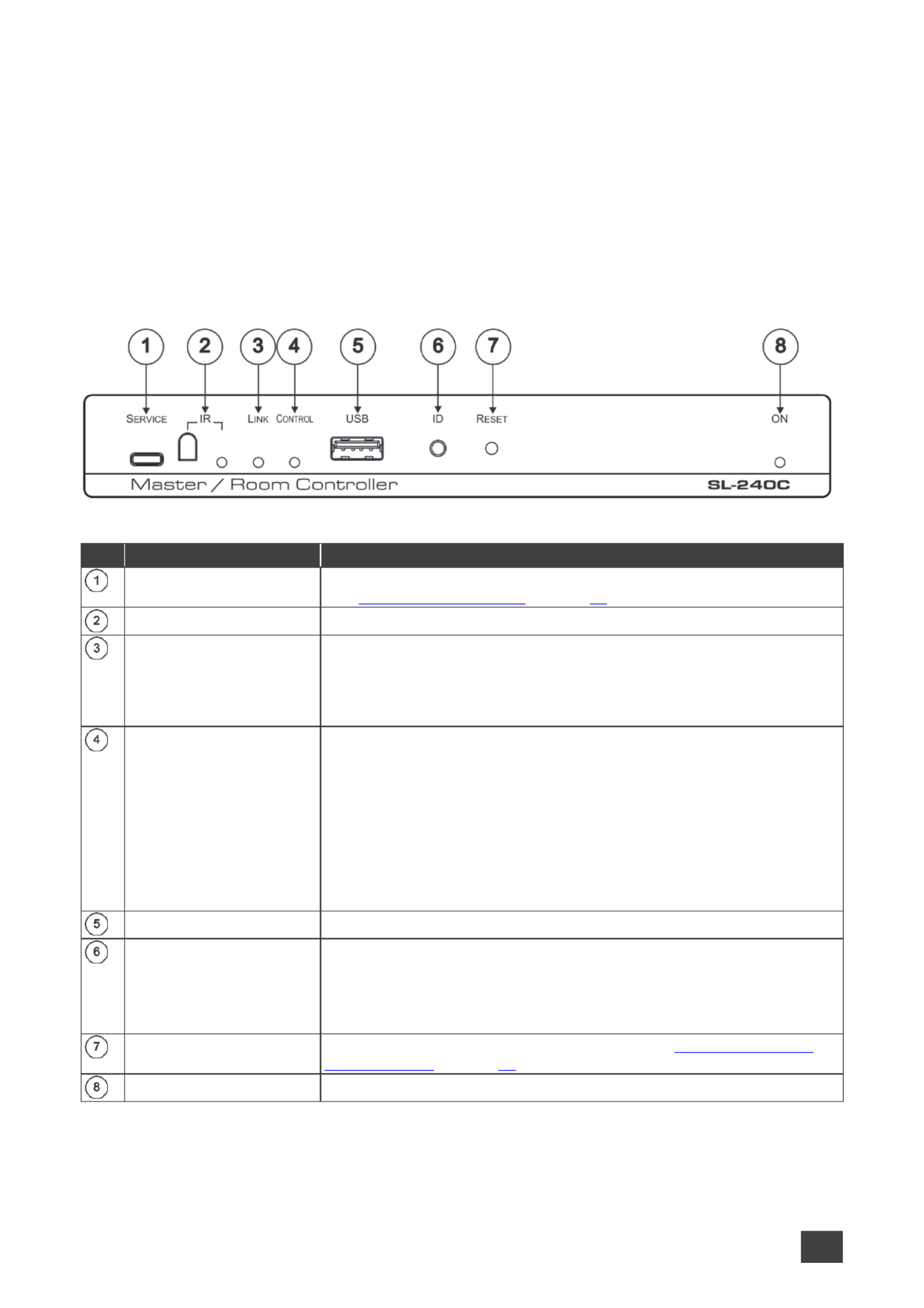
Figure 1 - Master / Room Controller & Kramer Control Brain Front Panel : SL 240C
#
Feature
Function
SERVICE Micro USB
Connector
Connect to a PC to send P3K commands perform a firmware upgrade and
(see on page ). Upgrading the Firmware 25
IR Receiver and LED
Detects IR signals for IR learning. Lights blue when in IR learning mode.
LINK LED
Lights blue to indicate Ethernet activity:
good connection On –
Flashing no connection –
Off before first connection –
CONTROL LED
Lights to indicate control states of the control application (Brain):
Flashing sending data –
Green ready and working –
White no devices are assigned –
Blue synchronizing –
Yellow one or more controlled devices are disconnected –
Red an error occurred –
Purple Brain booting up –
USB Connector
For future use.
ID Button
For self-identification over the network.
Press the button to send (broadcast) the #BEACON-INFO Protocol 3000
command.
Reply includes: IP address, port number, TCP port number, MAC UDP
address, and Model Name.
RESET Button
Press while performing a factory default reset (see Resetting to Factory
Default Settings on page 25.
ON LED
Lights green when powered on.
Kramer Electronics Ltd.
SL- Defining the SL-240C 240C –
Master / Room Controller & Kramer Control Brain
5
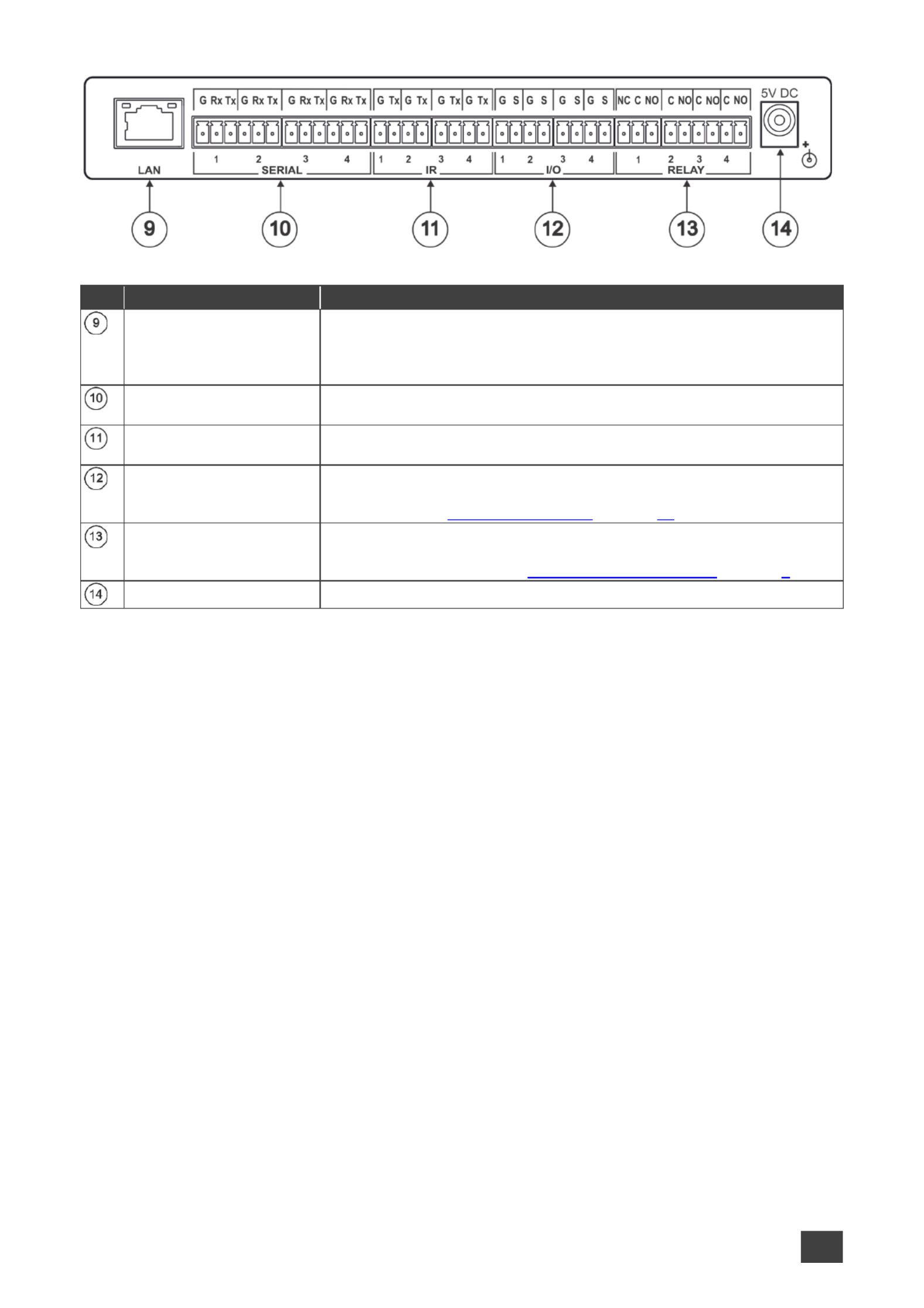
Figure 2 - Master / Room Controller & Kramer Control Brain Rear Panel : SL 240C
#
Feature
Function
LAN RJ-45 Connector
Connect to a local area network (supports PoE).
Indications:
LINK LED lights amber 1000/100/10MB connection. –
DATA LED flashes green Ethernet data link activity. –
SERIAL Ports (1 4–)
Terminal Block
Connect to up to 4 serial controlled devices for Ethernet- -RS232 , to
bidirectional tunnelin g.
IR Ports (1 4 –)
Terminal Block
Connect to up to 4 IR emitters or blasters.
I/O Ports (1 4) Terminal –
Block
Connect to up to 4 sensors or devices to be controlled, for example, a
motion sensor. Port may be configured as a digital input, digital output, or
analog input (see on page Configuring I/O Ports 15).
RELAY Ports (1 4–)
Terminal Block
Connect to up to 4 devices to be controlled by relay for example, a
motorized projection screen. 3 of the ports are NO and 1 port can be
connected as NO or NC (see on page Connecting the Relay Ports 8).
5V DC Power Socket
Connect to the power adapter and the mains electricity. to

Kramer Electronics Ltd.
SL- Installing in a Rack240C –
6
Installing in a Rack
This section provides instructions for rack mounting . Before installing in a rack, verify SL-240C
that the environment is within the recommended range:
Operation temperature 0 to 40 C (32 to 104 F). –
Storage temperature - to +70 C (-40 to +158 F). –40
Humidity 10% to 90%, RHL non-condensing. –
When installing on a 19" rack, avoid hazards by taking care that:
It is located within recommended environmental conditions. Operating ambient
temperature of a closed or multi-unit rack assembly may exceed ambient room
temperature.
Once rack mounted, there is enough air flow around . SL-240C
SL-240C is placed upright in the correct horizontal position.
You do not overload the circuit(s). When connecting to the supply circuit, SL-240C
overloading the circuits may have a detrimental effect on overcurrent protection and
supply wiring. Refer to the appropriate nameplate ratings for information. For example,
for fuse replacement, see the value printed on the product label.
SL-240C is earthed (grounded) and connected only to an electricity socket with
grounding. Pay particular attention when electricity is supplied indirectly (for example,
when the power cord is not plugged directly into the wall socket but to an extension
cable or power strip). Use only the supplied power cord.
To rack-mount -240C: SL
Mount the unit in a rack using an optional rack adapter (see the -1T2PT, RK-T2B RK
RK-2T1PT, RK-3T, RK-6T, RK-9T, RK-3TR, RK-4PT, , RK-T2SB User RK-T2B
Manual at: www.kramerav.com/product/RK-T2B#Tab_Resources).
Always mount SL-240C in the rack before connecting any cables or power.

Kramer Electronics Ltd.
SL- Connecting SL-240C240C –
7
Connecting -240C SL
Always switch off the power to each device before connecting it to your . After SL-240C
connecting your SL-240C, connect its power and then switch on the power to each device.
Figure 3: Connecting -240C SL
To connect - as illustrated in the example in SL 240C Figure 3, do the following:
1. Connect up to four bidirectional RS-232 devices to the SERIAL terminal block ports .
2. Connect up to four IR emitters or blasters to the IR terminal block ports .
3. Connect up to four GPIO (General Purpose I/O) devices to the I/O terminal block ports
. No more than 30V can be connected.
4. Connect up to four relay controlled devices to the RELAY terminal block ports (see
Connecting the Relay Ports on page 8).
5. Connect to a LAN through the LAN RJ-45 connector .
6. Use a PoE enabled Ethernet cable to receive power from the network connection
OR
connect the 5V DC power adapter to the power socket and to the mains electricity.

Kramer Electronics Ltd.
SL- Connecting SL-240C240C –
8
Connecting the Relay Ports
The normal state of the relay ports is as follows:
Port 1 can be connected as NO or NC (Normally Closed) –
Ports 2, 3 and 4 – NO (Normally Open)
Figure 4 Relay Ports :
To connect a ports as NO:
Connect the device to the C (Common) and NO terminals of the relevant port.
To connect port 1 as NC:
Connect the device to the C and NC terminal of port 1.

Kramer Electronics Ltd.
SL- Remote Operation via the Web Pages240C –
9
Remote Operation via the Web
Pages
SL-240C embedded webpages enable you to define device settings, configure communication
parameters, configure port settings, define security parameters, and view activity logs.
The specific parameter values shown in screenshots of this manual are merely
representative.
To access the web pages:
1. Enter the IP address of the device (see Default Communication Parameters on page 27)
in the address bar of your browser.
The Loading page appears followed shortly by the General Info page.
Figure 5 Embedded Web Pages General Info Page : –
The General Info page displays the following:
Model name
Firmware version
Serial number
Web pages version
2. Click the tabs on the left side of the screen to access the relevant web page.

Kramer Electronics Ltd.
SL- Remote Operation via the Web Pages240C –
10
Loading and Saving Configurations
You can save a configuration for easy recall in the future.
At the bottom left hand side of all web pages there is a and a Save button. These enable Load
you to save the current configuration and load any pre-saved configurations.
To load a configuration:
1. Click . Load
An Explorer window opens.
2. Select the required file and click . Open
The device is configured according to the saved preset.
To save the current configuration:
1. Configure the device as required.
2. Click . Save
The Save File window opens.
3. Browse to the required location to which to save the file.
4. Enter the required name for the saved preset.
5. Click . OK
The current configuration is saved.
When using Chrome, the file is automatically saved in the Downloads folder.

Kramer Electronics Ltd.
SL- Remote Operation via the Web Pages240C –
11
Viewing Connected Clients Information
SL-240C web pages enable you to view information for client devices that are connected to
SL-240C via Ethernet.
To view connected clients information:
1. Click Connected Clients on the left side of the web page (Figure 5).
The Connected Clients page appears.
Figure 6: Connected Clients Page
2. View the following connected clients information:
IP IP address –
To The - port to which it is connected –RS 232
Through Method of connection –
S/R Whether or not Send Replies is enabled for the port (see –Configuring the Serial
Ports on page 14).
Modifying Device Settings
SL-240C web pages enable you to modify the following device settings:
Device Name
Time and Date Settings

Kramer Electronics Ltd.
SL- Remote Operation via the Web Pages240C –
12
Changing the Device Name
SL-240C device name is used by DNS when addressing the device and is necessary for
accessing the device for the first time using a Web browser.
To change the name of your device:
1. Click Device Settings on the left side of the web page ( Figure 5).
The Device Settings page appears.
Figure 7: Device Settings Page
2. In the General info area, enter a new name in the Device name field.
The device name cannot include any spaces, can be up to 14 characters and can
include letters, numbers, hyphens and underscores only.
3. Click Save Changes.
Setting the Date and Time
SL-240C web pages enable you manually set the date and time for your device or to SL-240C
to use a time server to automatically set the date and time. Date and time settings are used by
the device for logging purposes (see on page ), for time driven events as Using the Log 23
defined through Kramer Control Buil , and for successfully connecting to the Kramer Control der
cloud for provisioning, publishing, and dashboard support.
To set the date and time for your device:
1. Click Device Settings on the left side of the web page ( Figure 5).
The Device Settings page appears ( Figure 7).
2. In the Time and Date area, if Use time server (NTP) is set to ON, click and click in OFF
the relevant fields to define the date, time and time zone.
– –OR
3. Click the ON button, enter the time server address in the Time server address field, and
click . Set

Kramer Electronics Ltd.
SL- Remote Operation via the Web Pages240C –
13
4. Click Save Changes.
Defining IP Settings
The default IP address setting for the device is DHCP . ON
To define static IP settings:
1. Click Communication on the left side of the web page ( Figure 5).
The Communication page appears.
Figure 8: Communication Page
2. In the Ethernet section, view the MAC address.
3. Click the DHCP button. OFF
4. Enter the required IP settings in the relevant fields.
5. Click . Set

Kramer Electronics Ltd.
SL- Remote Operation via the Web Pages240C –
14
Configuring the Serial Ports
SL-240C web pages enable you configure each of the serial ports . to
To configure a serial port:
1. Click Serial Ports Setting on the left side of the web page (Figure 5).
The Serial Ports Setting page appears.
Figure 9: Serial Ports Setting Page
2. In the Port area, click a port number (1 4 –).
3. In the Settings area, click or UDP TCP.
4. Enter the IP Port number.
5. Enter a TCP Keepalive value between 0 and 3600 seconds.
This value defines how often the unit sends a “keep alive” signal to the client. The default
value is 60 seconds.
6. Define the serial settings as necessary (see Default Communication Parameters on
page 27).
7. Select whether or not to send replies on the port to a new connected client by default,
(see Viewing Connected Clients Information on page 11).
8. Click Save Changes.

Kramer Electronics Ltd.
SL- Remote Operation via the Web Pages240C –
15
Configuring I/O Ports
SL-240C web pages enable you to configure each of the I/O port The I/O ports control s .
devices such as sensors, door locks, audio volume and lighting control devices .
To configure an I/O port:
1. Click GPIO Ports Settings on the left side of the web page (Figure 5).
The GPIO Ports Settings page appears.
Figure : GPIO Ports Settings Page Digital IN Trigger Type 10 –
2. In the Port area, click the number (1 4) of the port to be configured. –
3. In the Settings area, select one of the following from the Trigger type option box:
Digital Input (see Configuring a Digital In Trigger Typeput on page 16)
Digital Output (see Configuring a Digital Out Trigger Type on page 17)
Analog Input (see Configuring an Analog In Trigger Type on page ) 18
The settings available on the page change depending on which trigger type is selected.

Kramer Electronics Ltd.
SL- Remote Operation via the Web Pages240C –
16
Configuring a Digital Input Trigger Type
Digital Input trigger mode reads the digital input of an external sensor device that is connected
to the GPIO port, and detects High (upon passing Max threshold from Low state) or Low (upon
passing Min threshold from High state) port states according to the user defined voltage
threshold levels.
To configure a digital in trigger type: put
1. On the GPIO Ports Settings page, select Digital IN from the Trigger type option box
( Figure 10).
The Digital IN options appear ( Figure 10).
2. Select one of the following for the Pull-up resistor setting:
Enabled
Detection of an open circuit as High, or a short to ground as Low. This is suitable for
example, for a pushbutton switch (connecting one terminal of the switch to ground, and
the other to the input) or for an alarm closing a circuit that activates a series of actions.
When the pull- resistor is enabled, the port state is high and to be triggered it must be up
pulled low by the externally connected sensor.
Disabled
Suitable, for example, for a high temperature alarm that exceeds the maximum voltage
threshold.
When the pull- resistor is disabled, the port state is low and to be triggered it must be up
pulled high by the externally connected sensor.
3. Define the Min and Max for the Threshold VDC range (threshold voltage at which the
port changes state) and click . Set

Kramer Electronics Ltd.
SL- Remote Operation via the Web Pages240C –
17
Configuring a Digital Out Trigger Type
To configure a digital output trigger type:
1. On the GPIO Ports Settings page, select Digital OUT from the Trigger type option box
( Figure 10).
A Warning message appears.
Figure : Digital Out Selection Warning 11
2. Click . OK
The Digital OUT options appear.
Figure : GPIO Ports Settings Page Digital O Trigger Type 12 –UT
3. Select one of the following for the Pull-up resistor setting:
Pullup resistor enabled:
The port can be used for controlling devices that accept a TTL signal such as for
powering LEDs. The voltage output is TTL positive logic: high ~ 3.5V low ~ 0.3V. : ; :
When the pull-up resistor is enabled, the port state is high. For the state to be low,
you must click Low for the Current Status.
Pullup resistor disabled:
The port is used for controlling external devices such as room or light switches. The
external source device determines the voltage output; the maximum voltage is 30V
DC and the maximum current is 100mA.
When the pull-up resistor is disabled, the port state is low and to set it high, you must
click for the Current Status. High
Make sure that the current in this configuration does not exceed 100mA.
Kramer Electronics Ltd.
SL- Remote Operation via the Web Pages240C –
18
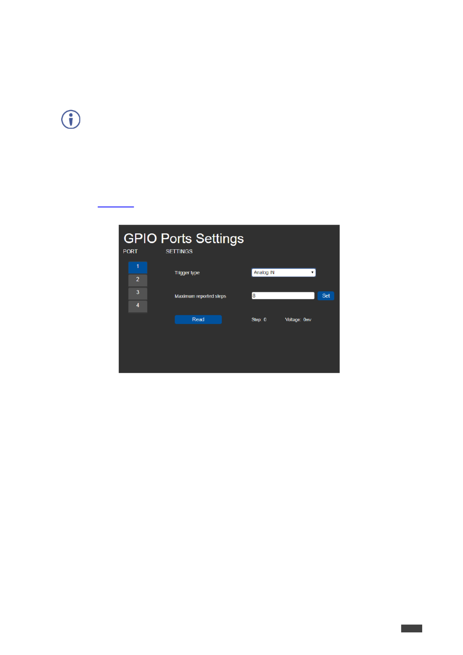
Configuring an Analog In Trigger Type
When you select the Analog IN trigger type, the port is triggered by an external analog device,
such as a volume control device. The trigger is activated once when the detected voltage is
within the 0 to 30V DC voltage range.
When the Analog trigger type is select , the Pullup resistor and Threshold settings IN ed
are disabled.
To configure an analog input trigger type:
1. On the GPIO Ports Settings page, select Analog IN from the Trigger type option box
( Figure 10).
The Analog IN options appear.
Figure : GPIO Port Settings Page Analog IN 13
2. Enter or use the arrows to scroll to a value (1 100) for the Maximum reported steps. –
This value is the number of steps that the analog input signal is divided into To .
calculate the voltage of each step, use the following formula:
Voltage of one step = 30V / number of steps

Kramer Electronics Ltd.
SL- Remote Operation via the Web Pages240C –
19
Changing the State of a Relay Port
SL-240C web pages enable you to change the state of each of the relay ports .
The relay ports have the following characteristics: SL-240C
Default state of relays 2 4 is NO (normally open) –
Default state of relay 1 can be NO or NC (normally closed), depending on how it is
connected to the device (see Connecting the Relay Po 8rts on page )
Rated at 30V DC and 1A
A non-latching relay function the contact is left in its default state when unpowered or –
in power up state. This means that if a relay is in its non-default state and power is lost,
the relay returns to its default state. To return it to its pre-power loss state, the setting
must be changed using either the web pages or a Protocol 3000 command.
To the state of a relay, (for example, relay 2): change
1. Click on the left side of the web page (Relay Ports Settings Figure 5).
The Relay Ports Settings page appears.
Figure : Relay Ports Settings Page 14
2. In the Port section, click the number (1 4) of the relay port to be changed. –
The current status of the selected relay appears.
3. Click . Close/Open
The relay changes to the selected state.
When relay connected as NC (see 1 is Connecting the Relay Ports on page ), the Current 8
status buttons are reversed.
Clicking Open closes the relay and clicking Close opens the relay.

Kramer Electronics Ltd.
SL- Remote Operation via the Web Pages240C –
20
Teaching IR Commands
SL-240C web pages enable you to teach SL-240C IR commands. These can be saved for
later use. The IR learning commands are in Pronto format.
While learning is in progress, the relevant LED on the front panel lights and IR SL-
240C is not available for normal operation.
At the start and end of learning a message is sent to all attached clients.
To teach a command to - : SL 240C
1. Click IR Command Learner on the left side of the web page ( Figure 5).
The IR Command Learner page appears.
Figure : IR Command Learner Page 15
2. Enter a name for the command in the first field.
3. Enter a value in the Learning timeout field.
This value defines how long the system waits to receive a command before exiting
learning mode.
4. Click Start Learning.
5. Position the IR remote control approximately 5cm to 7cm (2in 2.7 ) from the to in SL-
240C front panel.
6. Send a command with the remote control.
The command string received during the process appears in the Command received
box.

Kramer Electronics Ltd.
SL- Remote Operation via the Web Pages240C –
21
7. Click Copy.
The command string is copied to the clip board.
8. Paste the command string to control application. in a
Depending on the application, the format of the command string may have to be modified.
9. (Optional) Select the port on which to test the learned command and press the Test
play button.
The command runs on the selected port.
10. Click Save to save the new command.
11. To delete the current command, click . Clear
12. To retrieve a previously saved command, click Load.
Activating Device Security
SL-240C web pages enable you turn logon security (authentication) on or off. When security to
is on, access to the Web pages is granted only on submission of a valid user name and
password. For default logon credentials see Default Security Parameters on page 27.
To activate Web page security:
1. Click Security on the left side of the web page (Figure 5).
The Security page appears.
Figure : Security Page 16
2. Click . ON
A confirmation message appears.
Figure : Security Confirmation Message 17

Kramer Electronics Ltd.
SL- Remote Operation via the Web Pages240C –
22
3. Click . OK
The Authentication Required window appears.
Figure : Authentication Required Window 18
4. Enter the default username and password (see Default Security Parameters on page
27).
5. Click . OK
The web pages reload and the General Info page ( ) appears. Figure 5
6. Click Security on the left side of the web page.
The Security page appears with the Change Password settings.
Figure : Security Activated Page 19
7. If required, change the password and click . Change
Kramer Electronics Ltd.
SL- Remote Operation via the Web Pages240C –
23
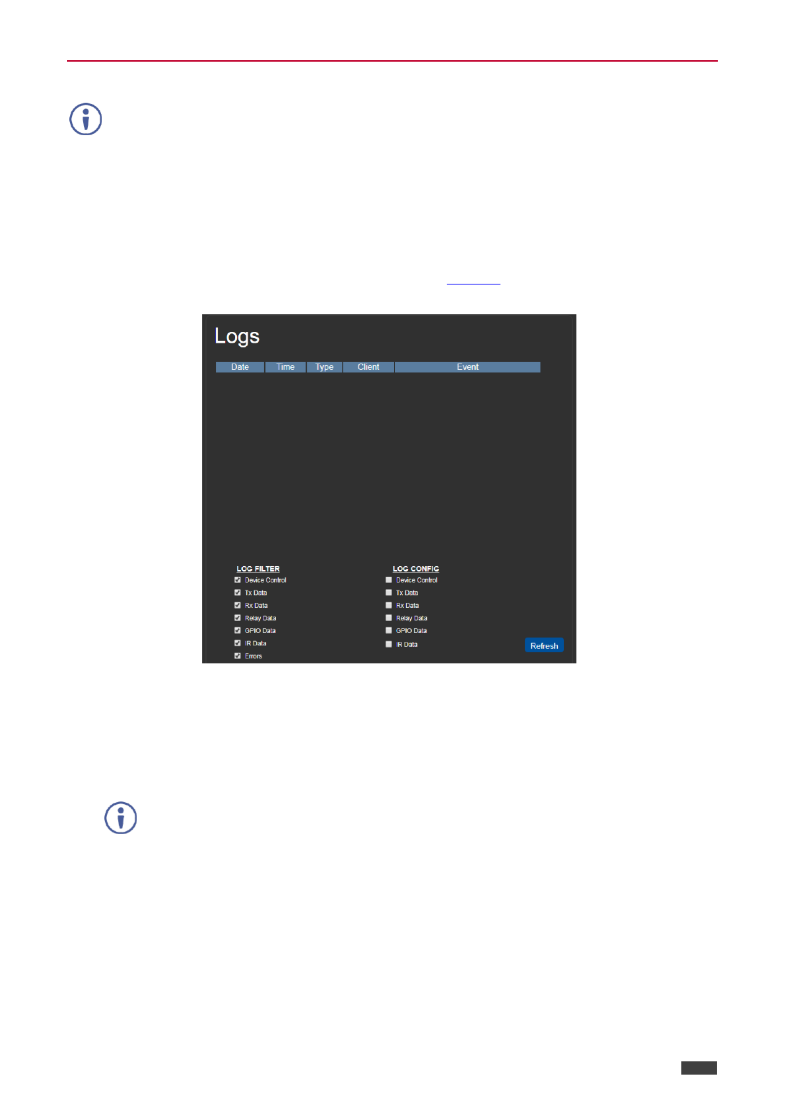
Using the L og
This feature is for future use and is not yet available.
SL-240C web pages enable you view the current log entries, search log entries with filters to
and configure the types of events the log records.
The log file is updated once per minute.
To use the log:
1. Click on the left side of the web page ( Logs Figure 5).
The page appears. Logs
Figure : Logs Page 20
2. Select any of the options in the Log Filter list to define which types of events are
displayed.
3. Select any of the options in the Log Config list to define which types of events are
recorded.
The display may not update automatically. Click to update the display. Refresh

Kramer Electronics Ltd.
SL- Remote Operation via the Web Pages240C –
24
About Us Page
Click About the left side of the web page ( ).to display the web page version and on Figure 5
Kramer company information.
Figure : About Us Page Example 21 –

Kramer Electronics Ltd.
SL- Resetting and Upgrading Firmware240C –
25
Resetting and Upgrading
Firmware
Resetting to Factory Default Settings
To reset the device to its factory default settings:
1. Press and hold the button on the rear panel for 6 seconds. RESET
2. Release the button. RESET
Wait for the reset process to complete.
The device is reset to the factory default settings.
Upgrading the Firmware
SL- 240C enables upgrading the device firmware via Ethernet or using the K-Upload USB
software application, available at
http://www.kramerav.com/product/SL-240C. For instructions on upgrading the firmware using
K-Upload, see the K-Upload User Manual.
It is recommended to upgrade the firmware via Ethernet.

Kramer Electronics Ltd.
SL- Technical Specifications240C –
26
Technical Specifications
Inputs
1 IR
Built- sensor (for learning) in
Outputs
4 IR
O -pin terminal block connectors n 2
4 Relays
1 (NC or NO)on a 3-pin terminal
block connector
3 (NO) on 2-pin terminal block
connectors
Ports
4 -232 Serial RS
O -pin terminal blocks n 3
4 GPI/O
O -pin terminal blocks n 2
1 Ethernet
On an -45 connector RJ
1 USB
On a USB Type-A connector (for
future use)
Processing
Processor Speed
1GHz
Memory
512MB RAM, 4GB Flash
Electrical
Power Consumption
5 DC, 2A V
Environmental
Conditions
Operating Temperature
0° to +40°C (32° to 104°F)
Storage Temperature
-40° to +70°C (-40° to 158°F)
Humidity
10% to 90%, RHL non-condensing
Regulatory
Compliance
Safety
CE
Enclosure
Size
MegaTOOLS® Mount 2 units —
side-by-side in a 1U rack space
with the optional rack RK–T2B
adapter.
Type
Aluminum
General
Net Dimensions (W, D, H)
18.75cm x 11.50cm x 2.54cm
(7.38" x 4.53" x 1.00" ) W, D, H
Shipping Dimensions (W, D, H)
34.50cm x 16.50cm x 5.20cm
(13.58" x 6.50" x 2.05" ) W, D, H
Net Weight
0.4kg (1.0lbs) approx.
Shipping Weight
1.0kg (2.2lbs) approx.
Accessories
Included
5V DC power adapter bracket set ,
Optional
RK-T2B rack adapter.
For optimum range and
performance use the
recommended USB, Ethernet,
serial and IR Kramer cables
available at
www.kramerav.com/product/SL-
240C
Specifications are subject to change without notice at www.kramerav.com

Kramer Electronics Ltd.
SL- Technical Specifications240C –
27
Default Communication Parameters
RS-232 over Micro USB
Baud Rate:
115200
Data Bits:
8
Stop Bits:
1
Parity:
None
Command Format:
ASCII
Example (Set configuration for port number 1 to digital input with the pull-up enabled): I/O
# - <CR>GPIO CFG 1,1,0,1
Ethernet
DHCP is enabled by factory default, the following are the default addresses if no DHCP server is found.
IP Address:
192.168.1.39
Subnet Mask:
255.255.0 .0
Default Gateway:
192.168.0.1
TCP Port #:
5000
Concurrent Connections TCP :
500
Full Factory Reset
Front panel buttons
Press and hold the button on the rear panel for 6 seconds. RESET
See on page . Resetting to Factory Default Settings 25
Default Security Parameters
Default User Name: Admin
Default Password: adminpw

Kramer Electronics Ltd.
SL- Protocol 3000240C –
28
Protocol 3000
The Master / Room Controller & Kramer Control Brain can be operated using the SL-240C
Kramer Protocol 3000 serial commands.
The command framing varies according to how you interface with a device. For example, a
basic video input switching command that routes a layer 1 video signal to HDMI out 1 from
HDMI input 2 ( ), is entered as follows: ROUTE 1,1,2
Terminal communication software, such as Hercules:
The above image is for illustration purposes only.
The framing of the command varies according to the terminal communication
software.
You can enter commands directly using terminal communication software (e.g., Hercules) by
connecting a PC to the serial or Ethernet port on . To enter press the Enter key SL-240C CR
( is also sent but is ignored by the command parser). LF
Commands sent from various non-Kramer controllers (e.g., Crestron) may require special
coding for some characters (such as, /X##). For more information, refer to your controller’s
documentation.
For more information about:
Using Protocol 3000 commands, see Understanding Protocol 3000 on page 29
General syntax used for Protocol 3000 commands, see Kramer Protocol 3000 Syntax on
page 30
Protocol 3000 commands available for , seeSL-240C Protocol 3000 Commands on page
31

Kramer Electronics Ltd.
SL- Protocol 3000240C –
29
Understanding Protocol 3000
Protocol 3000 commands are structured according to the following:
Command –A sequence of ASCII letters (A Z–, a-z - and ). A command and its
parameters must be separated by at least one space.
Parameters –A sequence of alphanumeric ASCII characters (0 9–, A Z–, a z– and some
special characters for specific commands). Parameters are separated by commas.
Message string –Every command entered as part of a message string begins with a
message starting character and ends with a message closing character.
A string can contain more than one command. Commands are separated by a
pipe ( ) character. The maximum string length is 64 characters. |
Message starting character:
# For host command/query –
~ For device response –
Query sign ? follows some commands to define a query request –
Message closing character:
CR Carriage return for host messages (ASCII 13) –
CR LF Carriage return for device messages (ASCII 13) and line-feed (ASCII 10) –
Command chain separator character –Multiple commands can be chained in the
same string. Each command is delimited by a pipe character ( ). When chaining |
commands, enter the message starting character and the message closing character
only at the beginning and end of the string.
Spaces between parameters or command terms
are ignored. Commands in the string do not
execute until the closing character is entered. A
separate response is sent for every command in
the chain.

Kramer Electronics Ltd.
SL- Protocol 3000240C –
30
Kramer Protocol 3000 Syntax
The Kramer Protocol 3000 syntax uses the following delimiters:
CR = Carriage return (ASCII 13 = 0x0D)
LF = Line feed (ASCII 10 = 0x0A)
SP = Space (ASCII 32 = 0x20)
Some commands have short name syntax in addition to long name syntax to enable faster
typing. The response is always in long syntax.
The Protocol 3000 syntax is in the following format:
Host Message Format:
Start
Address
(optional)
Body
Delimiter
#
Device_id@
Message
CR
Simple Command – Command string with only one command without addressing:
Start
Body
Delimiter
#
Command SP
Parameter_1,Parameter_2,…
CR
Command String Formal syntax with command concatenation and addressing: –
Start
Address
Body
Delimiter
#
Device_id@
Command_1
Parameter1_1,Parameter1_2,…|
Command_2
Parameter2_1,Parameter2_2,…|
Command_3
Parameter3_1,Parameter3_2,…|…
CR
Device Message Format:
Start
Address
(optional)
Body
Delimiter
~
Device_id@
Message
CR LF
Device Long Response Echoing command: –
Start
Address
(optional)
Body
Delimiter
~
Device_id@
Command [SP Param1 ,Param2
…] result
CR LF

Kramer Electronics Ltd.
SL- Protocol 3000240C –
31
Protocol Commands 3000
This section includes the following commands:
System Commands (page 31)
Communication Commands (page 38)
I/O Gateway Commands (page 45)
File System Commands (page 54)
Authentication Commands (page 58)
System Commands
Command
Description
#
Protocol handshaking
BUILD DATE -
Get device build date
FACTORY
Reset to factory default configuration
HELP
Get command list
LOG TAIL-
Get the last lines of message logs
MODEL
Get device model
NAME
Set/get machine (DNS) name
NAME RST-
Reset machine (DNS) name to factory default
PROT VER-
Get device protocol version
RESET
Reset device
SN
Get device serial number
TIME
Get/set device time and date
TIME LOC-
Get/set local time offset from UTC/GMT
VERSION
Get device firmware version
BUILD-DATE
Functions
Permission
Transparency
Set:
-
-
-
Get:
BUILD DATE?-
End User
Public
Description
Syntax
Set:
-
-
Get:
Get device build date
# BUILD DATE?- CR
Response
~ @ nn BUILD DATE- SP SP CRdate time LF
Parameters
date YYYY/MM/DD YYYY MM DD – Format: where = Year, = Month, = Day
time hh:mm:ss hh mm ss – Format: where = hours, = minutes, = seconds
Response Triggers
Notes
Example
#BUILD DATE?<CR>-
Kramer Electronics Ltd.
SL- Protocol 3000240C –
32
FACTORY
Functions
Permission
Transparency
Set:
FACTORY
End User
Public
Get:
-
-
-
Description
Syntax
Set:
Reset device to factory
default configuration
# FACTORYCR
Get:
-
-
Response
~ @ nn FACTORYSPOKCR LF
Parameters
Response Triggers
Notes
This command deletes all user data from the device. The deletion can take some time.
Power cycle the device after performing the reset to apply the changes.
Example
# FACTORY<CR>
HELP
Functions
Permission
Transparency
Set:
-
-
-
Get:
HELP
End User
Public
Description
Syntax
Set:
-
-
Get:
Get command list or help
for specific command
1. #HELPCR
2. #HELPSP CRcommand_name
Response
1. Multi-line: ~ @Device available protocol 3000 commands: nn CRLF
command, command...SP CR LF
2. Multi-line: ~ @HELP : : nn SPcommand CR LF CRdescription LFUSAGE usageCR LF
Parameters
command_name name of a specific command –
Response Triggers
Notes
Example
1. Get a list of all SL-240C commands:
# HELP<CR>
2. Get help for ETH-PORT command: the
# - HELP ETH PORT<CR>

Kramer Electronics Ltd.
SL- Protocol 3000240C –
33
LOG-TAIL
Function
Permission
Transparency
Set:
–
–
–
Get:
LOG TAIL?-
End User
Public
Description
Syntax
Set:
–
–
Get:
Get the last lines of
message logs
#LOG TAIL?- line_num
Response
Multi-line:
~ nn@LOG TAIL?-
Line #1 content
Line #2 content
Etc...
Parameters
line_num: the number of lines to display ( = the number of lines in the entire log). If this 1 n– n
parameter is omitted, it returns the last 20 lines of the log by default.
Response Triggers
Notes
Used for advanced troubleshooting. Helps find error root causes and gets details not displayed in the
error code number.
Example
Get the last lines of message logs: 20
# -LOG TAIL?<CR>
Get the last 50 lines of message logs:
# -LOG TAIL? 50<CR>

Kramer Electronics Ltd.
SL- Protocol 3000240C –
34
MODEL
Functions
Permission
Transparency
Set:
-
-
-
Get:
MODEL?
End User
Public
Description
Syntax
Set:
-
-
Get:
Get device model
# MODEL?CR
Response
~ @ nn MODELSP CRmodel_name LF
Parameters
model_name String of up to 19 printable ASCII chars –
Response Triggers
Notes
Example
# MODEL?<CR>
NAME
Functions
Permission
Transparency
Set:
NAME
Administrator
Public
Get:
NAME?
End User
Public
Description
Syntax
Set:
Set machine (DNS) name
# NAMESP CRmachine_name
Get:
Get machine (DNS) name
# NAME?CR
Response
~ @ nn NAME?SP CRmachine_name LF
Parameters
machine_name–String of up to 14 alpha-numeric characters (can include hyphens but not at the
beginning or end)
Response Triggers
Notes
The machine name is not the same as the model name. The machine name is used to identify a
specific machine or a network in use (with DNS feature on).
Example
Set the DNS name of the device to “room 442”:-
# -NAME room 442<CR>
Kramer Electronics Ltd.
SL- Protocol 3000240C –
35
NAME-RST
Functions
Permission
Transparency
Set:
NAME RST-
Administrator
Public
Get:
-
-
-
Description
Syntax
Set:
Reset machine (DNS)
name to factory default
# NAME RST- CR
Get:
-
-
Response
~ @ nn NAME RST OK- SP CR LF
Parameters
Response Triggers
Notes
Factory default of machine (DNS) name is “ ”SL- 0C-XXXXXX24 , where XXXXXXX = the last 6 digits of
the serial number.
Example
Reset the DNS name of the device to the factory default:
# -NAME RST<CR>
PROT- VER
Functions
Permission
Transparency
Set:
-
-
-
Get:
PROT VER?-
End User
Public
Description
Syntax
Set:
-
-
Get:
Get device protocol
version
# PROT VER?- CR
Response
~ @ nn PROT VER- SP3000: CRversion LF
Parameters
version–XX.XX where X is a digit
Response Triggers
Notes
Example
# - PROT VER?<CR>

Kramer Electronics Ltd.
SL- Protocol 3000240C –
36
RESET
Functions
Permission
Transparency
Set:
RESET
Administrator
Public
Get:
-
-
-
Description
Syntax
Set:
Reset device
# RESETCR
Get:
-
-
Response
~ @ nn RESET OKSP CR LF
Parameters
Response Triggers
Notes
Example
# RESET<CR>
SN
Functions
Permission
Transparency
Set:
-
-
-
Get:
SN?
End User
Public
Description
Syntax
Set:
-
-
Get:
Get device serial
number
# SN?CR
Response
~ @ nn SNSP CRserial_number LF
Parameters
serial_number–14 digits, factory assigned
Response Triggers
Notes
This device has a 14 digit serial number.
Example
# SN?<CR>
Kramer Electronics Ltd.
SL- Protocol 3000240C –
37
TIME
Functions
Permission
Transparency
Set:
TIME
Administrator
Public
Get:
TIME?
End User
Public
Description
Syntax
Set:
Set device time and date
#TIME␠ ␍day_of_week,date,time
Get:
Get device time and
date
#TIME?␍
Response
~ nn@TIME␠ ␍␊day_of_week,date,time
Parameters
day_of_week options: – SUN,MON,TUE,WED,THU,FRI,SAT
date DD MM YYYY format: – - -
time hh:mm:ss format: –
Response Triggers
Notes
The year must be 4 digits
The device does not validate the day of week from the date
Time format 24 hours –
Date format Day, Month, Year –
Example
Set device time to Monday, August 8, 2017 at 3:00pm:
# - - : : TIME MON,29 08 2017,15 00 00<CR>
TIME-LOC
Functions
Permission
Transparency
Set:
TIME LOC-
End User
Public
Get:
TIME LOC?-
End User
Public
Description
Syntax
Set:
Set local time offset from
UTC/GMT
#TIME LOC- ␠ ␍UTC_off,DayLight
Get:
Get local time offset
from UTC/GMT
#TIME LOC?- ␍
Response
~ nn@TIME LOC- ␠ ␍␊UTC_off,DayLight
Parameters
UTC_off offset of device local time from UTC/GMT (without daylight time correction) – :
-12 (subtract 12 hours from UTC/GMT) – 14 (add 14 hours to UTC/GMT)
DayLight – use , see notes. 0
Response Triggers
Notes
This command is relevant only if the time server is configured.
Device time calculates by adding UTC_off to UTC time (that it got from the time server) + 1 hour if
daylight savings time is in effect.
The parameter is no longer in use, because daylight savings time information is received DayLight
from the time server. This parameter is maintained only for backward compatibility.
The command sets the device time without considering these settings. TIME
Example
Set device local time to US EST (Eastern Standard Time = - UTC/GMT): 5
# - - 0 TIME LOC 5, <CR>
Kramer Electronics Ltd.
SL- Protocol 3000240C –
38
VERSION
Functions
Permission
Transparency
Set:
-
-
-
Get:
VERSION?
End User
Public
Description
Syntax
Set:
-
-
Get:
Get firmware version
number
# VERSION?CR
Response
~ @ nn VERSIONSP CRfirmware_version LF
Parameters
firmware_version where the digit groups are: major.minor.build version –XX.XX.XXXX
Response Triggers
Notes
Example
# VERSION?<CR>
Communication Commands
Command
Description
BEACON INFO-
Get beacon information, including IP address, UDP control port, TCP control port, MAC
address, model, name
ETH PORT -
Set/get Ethernet port protocol
NET CONFIG-
Set a network configuration
NET DHCP-
Set/get DHCP mode
NET DNS-
Get DNS name server
NET GATE -
Set/get gateway IP
NET IP -
Set/get IP address
NET MAC-
Get MAC address
NET MASK-
Set/get subnet mask
TIME SRV-
Get/set time server
UART
Get/set com port configuration

Kramer Electronics Ltd.
SL- Protocol 3000240C –
39
BEACON-INFO
Functions
Permission
Transparency
Set:
–
–
–
Get:
BEACON INFO?-
End User
Public
Description
Syntax
Set:
–
–
Get:
Get beacon information,
including IP address,
UDP control port, TCP
control port, MAC
address, model, name
#BEACON INFO?- ␠ ␍port_id
Response
~nn@BEACON-INFO␠port_id,ip_string,udp_port,tcp_port,mac_address,model,
name␍␊
Parameters
port_id – ID of the Ethernet port (wired Ethernet connection). and higher (for future use). , 0 1
ip_string –dot-separated representation of the IP address
udp_port UDP control port –
tcp_port TCP control port –
mac_address dash-separated MAC address –
model –device model
name device name –
Response Triggers
After execution, notification is sent containing beacon information.
Notes
There is no Set command.
The parameter is not necessary and can be omitted. port_id
Example
Get beacon information for port 0:
# - BEACON INFO? 0<CR>
Termékspecifikációk
| Márka: | Kramer |
| Kategória: | vezérlő |
| Modell: | SL-240C |
Szüksége van segítségre?
Ha segítségre van szüksége Kramer SL-240C, tegyen fel kérdést alább, és más felhasználók válaszolnak Önnek
Útmutatók vezérlő Kramer

19 Augusztus 2024
19 Augusztus 2024
18 Augusztus 2024
18 Augusztus 2024
18 Augusztus 2024
17 Augusztus 2024
17 Augusztus 2024
16 Augusztus 2024
16 Augusztus 2024
15 Augusztus 2024
Útmutatók vezérlő
- vezérlő Samsung
- vezérlő Sony
- vezérlő Yamaha
- vezérlő Nedis
- vezérlő Philips
- vezérlő Pioneer
- vezérlő Garmin
- vezérlő Canon
- vezérlő StarTech.com
- vezérlő HyperX
- vezérlő Sven
- vezérlő HP
- vezérlő Saramonic
- vezérlő SBS
- vezérlő JBL
- vezérlő Hunter
- vezérlő Zebra
- vezérlő Dell
- vezérlő Boss
- vezérlő Crestron
- vezérlő Tripp Lite
- vezérlő Allen & Heath
- vezérlő Thomson
- vezérlő Esperanza
- vezérlő Juniper
- vezérlő Reely
- vezérlő Hikvision
- vezérlő Eurolite
- vezérlő Vivanco
- vezérlő Microsoft
- vezérlő Asus
- vezérlő Rain Bird
- vezérlő Hama
- vezérlő Zoom
- vezérlő Korg
- vezérlő Mitsubishi
- vezérlő Gossen Metrawatt
- vezérlő Synology
- vezérlő Hori
- vezérlő Polsen
- vezérlő Supermicro
- vezérlő Genesis
- vezérlő Bose
- vezérlő Thrustmaster
- vezérlő BeamZ
- vezérlő Tangent
- vezérlő COLBOR
- vezérlő Logitech
- vezérlő SPL
- vezérlő TOA
- vezérlő Parrot
- vezérlő American DJ
- vezérlő Scosche
- vezérlő Smart-AVI
- vezérlő DJI
- vezérlő Amazon
- vezérlő MSI
- vezérlő Gembird
- vezérlő Cisco
- vezérlő Denon
- vezérlő ATen
- vezérlő Niceboy
- vezérlő Speed-Link
- vezérlő Steelplay
- vezérlő Behringer
- vezérlő Bogen
- vezérlő Showtec
- vezérlő Carel
- vezérlő Chauvet
- vezérlő DreamGEAR
- vezérlő PreSonus
- vezérlő Steelseries
- vezérlő Manhattan
- vezérlő Spektrum
- vezérlő Plantronics
- vezérlő Honeywell
- vezérlő Broan
- vezérlő Marshall
- vezérlő Velleman
- vezérlő Russound
- vezérlő Media-Tech
- vezérlő Monacor
- vezérlő Zephyr
- vezérlő One For All
- vezérlő IK Multimedia
- vezérlő ION
- vezérlő Manta
- vezérlő Apricorn
- vezérlő Datapath
- vezérlő Razer
- vezérlő Mackie
- vezérlő Infinity
- vezérlő Trust
- vezérlő AKAI
- vezérlő Konig
- vezérlő Pyle
- vezérlő MuxLab
- vezérlő Lumens
- vezérlő Rolls
- vezérlő IFM
- vezérlő DataVideo
- vezérlő Dangerous Music
- vezérlő Atlona
- vezérlő Schneider
- vezérlő Lindy
- vezérlő NACON
- vezérlő Danfoss
- vezérlő Areca
- vezérlő Steca
- vezérlő Atlas Sound
- vezérlő Marshall Electronics
- vezérlő Cameo
- vezérlő Audac
- vezérlő Siig
- vezérlő Novation
- vezérlő Gefen
- vezérlő Homematic IP
- vezérlő HQ Power
- vezérlő RCA
- vezérlő Somfy
- vezérlő AViPAS
- vezérlő Nintendo
- vezérlő Magnus
- vezérlő Thermaltake
- vezérlő Kicker
- vezérlő DBX
- vezérlő Genius
- vezérlő Adj
- vezérlő Numark
- vezérlő IVT
- vezérlő Clarity
- vezérlő Tascam
- vezérlő Alfatron
- vezérlő Astro
- vezérlő Savio
- vezérlő 8BitDo
- vezérlő Belkin
- vezérlő RGBlink
- vezérlő PTZ Optics
- vezérlő KanexPro
- vezérlő BZBGear
- vezérlő Manfrotto
- vezérlő AMX
- vezérlő American Audio
- vezérlő Draper
- vezérlő Thermador
- vezérlő SilverStone
- vezérlő Targus
- vezérlő Jumbo
- vezérlő Sonance
- vezérlő Da-Lite
- vezérlő Ednet
- vezérlő Perel
- vezérlő Bigben Interactive
- vezérlő GeoVision
- vezérlő Valcom
- vezérlő Bigben
- vezérlő Naxa
- vezérlő Carat
- vezérlő Intel
- vezérlő Sherwood
- vezérlő Sweex
- vezérlő Vizio
- vezérlő Vakoss
- vezérlő Metronic
- vezérlő Aruba
- vezérlő Natec
- vezérlő Ikan
- vezérlő T'nB
- vezérlő Tracer
- vezérlő ESI
- vezérlő Schaudt
- vezérlő GVM
- vezérlő Irritrol
- vezérlő Vaddio
- vezérlő Jung
- vezérlő Apart
- vezérlő Saitek
- vezérlő Turtle Beach
- vezérlő Radial Engineering
- vezérlő Fusion
- vezérlő Xtreme
- vezérlő IHome
- vezérlő Senal
- vezérlő Krom
- vezérlő Monoprice
- vezérlő Fostex
- vezérlő ASTRO Gaming
- vezérlő OSD Audio
- vezérlő AirTurn
- vezérlő Adaptec
- vezérlő Big Ben
- vezérlő Contour Design
- vezérlő Sonifex
- vezérlő Xantech
- vezérlő Ganz
- vezérlő Movistar
- vezérlő Konix
- vezérlő Auray
- vezérlő Logic3
- vezérlő GOgroove
- vezérlő Morningstar
- vezérlő Kanlux
- vezérlő HID Identity
- vezérlő LYYT
- vezérlő Venom
- vezérlő PDP
- vezérlő Inovonics
- vezérlő Gioteck
- vezérlő MOZA
- vezérlő Robitronic
- vezérlő Icon
- vezérlő Premier Mounts
- vezérlő Aquatic AV
- vezérlő Tru Components
- vezérlő Elite Screens
- vezérlő KONFTEL
- vezérlő PowerA
- vezérlő LSI
- vezérlő Phoenix Contact
- vezérlő Softube
- vezérlő SmartAVI
- vezérlő RiotPWR
- vezérlő Highpoint
- vezérlő Leviton
- vezérlő EtiamPro
- vezérlő PCE Instruments
- vezérlő SecurityMan
- vezérlő Ltech
- vezérlő Canyon
- vezérlő Hotone
- vezérlő IPEGA
- vezérlő Dadson
- vezérlő Niles
- vezérlő Rachio
- vezérlő Ledxon
- vezérlő Blizzard Lighting
- vezérlő Trenton Systems
- vezérlő Heath Zenith
- vezérlő Gamesir
- vezérlő Lab Gruppen
- vezérlő Heritage Audio
- vezérlő CTA Digital
- vezérlő Re.corder
- vezérlő Snakebyte
- vezérlő Nyko
- vezérlő EXSYS
- vezérlő Amer
- vezérlő ALC
- vezérlő Kanex
- vezérlő Audibax
- vezérlő Mitzu
- vezérlő CoolerMaster
- vezérlő Dragonshock
- vezérlő Atlantis Land
- vezérlő Universal Remote Control
- vezérlő LumenRadio
- vezérlő Circle
- vezérlő Victrix
- vezérlő Axor
- vezérlő HuddleCamHD
- vezérlő Balam Rush
- vezérlő Visual Productions
Legújabb útmutatók vezérlő
2 Április 2025
30 Március 2025
30 Március 2025
30 Március 2025
30 Március 2025
30 Március 2025
28 Március 2025
27 Március 2025
27 Március 2025
14 Január 2025