Használati útmutató JVC DLA-RS48
Olvassa el alább 📖 a magyar nyelvű használati útmutatót JVC DLA-RS48 (170 oldal) a Beamer kategóriában. Ezt az útmutatót 9 ember találta hasznosnak és 2 felhasználó értékelte átlagosan 4.5 csillagra
Oldal 1/170

DILA
PROJECTOR
DLARS66
DLARS56
DLARS48
DLARS46
Pour utilisation par le client :
Entrerci-dessous le N°de série qui
est situé sous le boîtier. Garder
cetteinformation comme référence
pour le futur.
Instrucción para el cliente :
Introduzca a continuación el nº de
serie que aparece en la parte
inferior lateral de la caja. Conserve
esta información como referencia
para uso ulterior.
For Customer use :
Enter below the serial No. which is
located on the side of the cabinet.
Retain this information for future
reference.
DLA-RS66 / DLA-RS56 /
DLA-RS48 / DLA-RS46
Model No.
Serial No.
DLA-RS66 / DLA-RS56 /
DLA-RS48 / DLA-RS46
N° de modèle
N° de série
DLA-RS66 / DLA-RS56 /
DLA-RS48 / DLA-RS46
Modelo Nº
Nº de serie
ENGLISH
FRANÇAIS
ESPAÑOL/CASTELLANO
INSTRUCTIONS
PC023482999
Getting Started TroubleshootingSet upOperate Adjust/Set Maintenance Others

SafetyPrecautions
晼㯡婌♟㒷
IMPORTANT INFORMATION
This product has a High Intensity
Dis-charge (HID) lamp that contains
mercury.
Disposal of these materials may be
regulated in your community due to
environmental considerations. For
disposal or recycling information,
please contact your local authorities or
for USA, the Electronic Industries
Alliance: http://www.eiae.org.
WARNING:
TO PREVENT FIRE OR SHOCK HAZARDS, DO
NOT EXPOSE THIS APPLIANCE TO RAIN OR
MOISTURE.
MACHINE NOISE INFORMATION
(Germany only)
Changes Machine Noise Information Ordinance 3.
GSGV, January 18, 1991: The sound pressure level
at the operator position is equal or less than 20 dB
(A) according to ISO 7779.
FCC INFORMATION (U.S.A. only)
CAUTION:
Changes or modification not approved by JVC could
void the user’s authority to operate the equipment.
Declaration of Conformity
Model Number : DLA-RS66U/DLA-RS56U/
DLA-RS48U/DLA-RS46U
Trade Name : JVC
Responsible party : JVC AMERICAS CORP.
Address : 1700 Valley Road Wayne, N. J. 07470
Telephone Number : 973-317-5000
This device complies with Part 15 of FCC Rules.
Operation is subject to the following two conditions:
(1) This device may not cause harmful interference,
and (2) this device must accept any interference
received, including interference that may cause
undesired operation.
About the installation place
Do not install the projector in a place that cannot
support its weight securely.
If the installation place is not sturdy enough, the
projector could fall or overturn, possibly causing
personal injury.
Reorient or relocate the receiving antenna.
Increase the separation between the equipment
and receiver.
Consult the dealer or an experienced radio/TV
technician for help.
Connect the equipment into an outlet on a circuit
different from that to which the receiver is
connected.
NOTE:
This equipment has been tested and found to comply
with the limits for Class B digital devices, pursuant to
Part 15 of the FCC Rules. These limits are designed
to provide reasonable protec tion against harmful
interference in a residential installation. This
equipment generates, uses, and can radiate radio
frequency energy and, if not installed and used in
accordance with the instruc tions, may cause harmful
interference to radio communications. However,
there is no guarantee that interference will not occur
in a particular installation. If this equipment does
cause harmful interference to radio or television
reception, which can be determined by turning the
equipment off and on, the user is encourage to try to
correct the interference by one or more of the
following measures:
WARNING:
THIS APPARATUS MUST BE EARTHED.
CAUTION:
For the customers in Taiwan only
To reduce the risk of electric shock, do not remove
cover. Refer servicing to qualified service personnel.
This projector is equipped with a 3-blade grounding
type plug to satisfy FCC rule. If you are unable to
insert the plug into the outlet, contact your electrician.
2
GettingStarted

150 mm and above
150 mm
and above
300 mm
and above
200 mm
and above
300 mm
and above
PORTABLE CART WARNING
(symbol provided by RETAC)
S3126A
Front
-
-
-
-
-
-
-
-
-
-
-
-
-
IMPORTANT SAFEGUARDS
Electrical energy can perform many useful functions.
This unit has been engineered and manufactured to
assure your personal safety. But IMPROPER USE
CAN RESULT IN POTENTIAL ELECTRICAL
SHOCK OR FIRE HAZARD. In order not to defeat
the safeguards incorporated into this product,
observe the following basic rules for its installation,
use and service. Please read these Important
Safeguards carefully before use.
All the safety and operating instructions should be read
before the product is operated.
The safety and operating instructions should be retained for
future reference.
All warnings on the product and in the operating
instructions should be adhered to.
All operating instructions should be followed.
Place the projector near a wall outlet where the plug can be
easily unplugged.
Unplug this product from the wall outlet before cleaning.
Do not use liquid cleaners or aerosol cleaners. Use a damp
cloth for cleaning.
Do not use attachments not recommended by the product
manufacturer as they may be hazardous.
Do not use this product near water. Do not use immediately
after moving from a low temperature to high temperature,
as this causes condensation, which may result in fire,
electric shock, or other hazards.
Do not place this product on an unstable cart, stand, or
table. The product may fall, causing serious injury to a child
or adult, and serious damage to the product. The product
should be mounted according to the manufacturer’s
instructions, and should use a mount recommended by the
manufacturer.
When the product is used on a cart,
care should be taken to avoid quick
stops, excessive force, and uneven
surfaces which may cause the product
and cart to overturn, damaging
equipment or causing possible injury to
the operator.
Slots and openings in the cabinet are provided for
ventilation. These ensure reliable operation of the product
and protect it from overheating. These openings must not
be blocked or covered. (The openings should never be
blocked by placing the product on bed, sofa, rug, or similar
surface. It should not be placed in a built-in installation such
as a bookcase or rack unless proper ventilation is provided
and the manufacturer’s instructions have been adhered to.)
To allow better heat dissipation, keep a clearance between
this unit and its surrounding as shown below. When this unit
is enclosed in a space of dimensions as shown below, use
an air-conditioner so that the internal and external
temperatures are the same. Overheating can cause
damage.
-
-
-
-
-
-
-
-
-
-
-
-
a)
b)
c)
d)
e)
f)
When the power supply cord or plug is damaged.
If liquid has been spilled, or objects have fallen on the
product.
If the product has been exposed to rain or water.
If the product does not operate normally by following the
operating instructions. Adjust only those controls that
are covered by the Operation Manual, as an improper
adjustment of controls may result in damage and will
often require extensive work by a qualified technician to
restore the product to normal operation.
If the product has been dropped or damaged in any
way.
When the product exhibits a distinct change in
performance, this indicates a need for service.
When replacement parts are required, be sure the service
technician has used replacement parts specified by the
manufacturer or with same characteristics as the original
part. Unauthorized substitutions may result in fire, electric
shock, or other hazards.
Upon completion of any service or repairs to this product,
ask the service technician to perform safety checks to
determine that the product is in proper operating condition.
The product should be placed more than one foot away
from heat sources such as radiators, heat registers, stoves,
and other products (including amplifiers) that produce heat.
When connecting other products such as VCR’s, and DVD
players, you should turn off the power of this product for
protection against electric shock.
Power source indicated on the label. If you are not sure of
the type of power supply to your home, consult your
product dealer or local power company.
This product is equipped with a three-wire plug. This plug
will fit only into a grounded power outlet. If you are unable
to insert the plug into the outlet, contact your electrician to
install the proper outlet. Do not defeat the safety purpose of
the grounded plug.
Power-supply cords should be routed so that they are not
likely to be walked on or pinched by items placed upon or
against them. Pay particular attention to cords at doors,
plugs, receptacles, and the point where they exit from the
product.
For added protection of this product during a lightning
storm, or when it is left unattended and unused for long
periods of time, unplug it from the wall outlet and
disconnect the cable system. This will prevent damage to
the product due to lightning and power line surges.
Do not overload wall outlets, extension cords, or
convenience receptacles on other equipment as this can
result in a risk of fire or electric shock.
Never push objects of any kind into this product through
openings as they may touch dangerous voltage points or
short out parts that could result in a fire or electric shock.
Never spill liquid of any kind on the product.
Do not attempt to service this product yourself as opening
or removing covers may expose you to dangerous voltages
and other hazards. Refer all service to qualified service
personnel.
Unplug this product from the wall outlet and refer service to
qualified service personnel under the following conditions:
3
GettingStarted

-
-
-
-
-
-
-
-
-
-
-
Do not place combustibles behind the cooling fan. For
example, cloth, paper, matches, aerosol cans or gas
lighters that present special hazards when over heated.
Do not look into the projection lens while the illumination
lamp is turned on. Exposure of your eyes to the strong light
can result in impaired eyesight.
Do not look into the inside of this unit through vents
(ventilation holes), etc. Do not look at the illumination lamp
directly by opening the cabinet while the illumination lamp is
turned on. The illumination lamp also contains ultraviolet
rays and the light is so powerful that your eyesight can be
impaired.
Do not drop, hit, or damage the light-source lamp (lamp
unit) in any way. It may cause the light-source lamp to
break and lead to injuries. Do not use a damaged light
source lamp. If the light-source lamp is broken, ask your
dealer to repair it. Fragments from a broken light-source
lamp may cause injuries.
The light-source lamp used in this projector is a high
pressure mercury lamp. Be careful when disposing of the
light-source lamp. If anything is unclear, please consult
your dealer.
Do not ceiling-mount the projector to a place which tends to
vibrate; otherwise, the attaching fixture of the projector
could be broken by the vibration, possibly causing it to fall
or overturn, which could lead to personal injury.
Use only the accessory cord designed for this product to
prevent shock.
For health reasons, please take a break of about 5-15
minutes every 30-60 minutes and let your eyes rest. Please
refrain from watching any 3D-images when you feel tired,
unwell or if you feel any other discomfort. Moreover, in case
you see a double image, please adjust the equipment and
software for proper display. Please stop using the unit if the
double image is still visible after adjustment.
Once every three years, please perform an internal test.
This unit is provided with replacement parts needed to
maintain its function (such as cooling fans). Estimated
replacement time of parts can vary greatly depending on
frequency of use and the respective environment. For
replacement, please consult your dealer, or the nearest
authorized JVC service center.
When fixing the unit to the ceiling, Please note that we do
not take any responsibility, even during the warranty period,
if the product is damaged due to use of metal fixtures used
for fixation to the ceiling other than our own or if the
installation environment of said metal fixtures is not
appropriate. If the unit is suspended from the ceiling during
use, please be careful in regard to the ambient temperature
of the unit. If you use a central heating, the temperature
close to the ceiling will be higher than normally expected.
Video images can burn into the electronic com ponent
parts. Please do not display screens with still images of
high brightness or high contrast, such as found in video
games and computer programs. Over a long period of time
it might stick to the picture element. There is no problem
with the playback of moving images, e.g. normal video
footage.
-
-
-
-
-
-
-
Video images can burn into the electronic com ponent
parts. Please do not display screens with still images of
high brightness or high contrast, such as found in video
games and computer programs. Over a long period of time
it might stick to the picture element. There is no problem
with the playback of moving images, e.g. normal video
footage.
Not using the unit for a long time can lead to malfunction.
Please power it on and let it run occasionally. Please avoid
using the unit in a room where cigarettes are smoked. It is
impos sible to clean optical component parts if they are
contaminated by nicotine or tar. This might lead to
performance degradation.
Please watch from a distance three times the height of the
projected image size. Persons with photosensitivity, any
kind of heart disease, or weak health should not use 3D
glasses.
Watching 3D-images might be cause of illness. If you feel
any change in your physical condition, please stop
watching immediately and consult a physician if necessary.
When watching 3D images, it is recommended to take
regular breaks. As the length and frequency of the required
breaks differ for every person, please judge according to
your own condition.
If your child watches while wearing 3D glasses, it should be
accompanied by its parents or an adult guardian. The adult
guardian should be careful to avoid situations where the
child’s eyes might become tired, as responses to tiredness
and discomfort, etc., are hard to detect, and it is possible
for the physical condition to deteriorate very quickly. As the
visual sense is not yet fully developed in children under the
age of 6, please consult a physician in regard to any
problem concerning 3D-images if necessary.
Note that when using the 3D feature, the video output may
appear different from the original video image due to image
conversion on the device.
* DO NOT allow any unqualified person to
install the unit.
Be sure to ask your dealer to install the unit
(e.g.attaching it to the ceiling) since special
technical knowledge and skills are required for
installation. If installation is performed by an
unqualified person, it may cause personal injury or
electrical shock.
4
GettingStarted

Power cord
Power cord
For European continent
countries
For United Kingdom
Green-and-yellow
Blue
Brown
Fuse
: Earth
: Neutral
: Live
POWER CONNECTION
WARNING:
WARNING:
Do not cut off the main plug from this
equipment.
The power supply voltage rating of this product is
AC110V – AC240V. Use only the power cord
designated by our dealer to ensure Safety and EMC.
Ensure that the power cable used for the projector is
the correct type for the AC outlet in your country.
Consult your product dealer.
If the plug fitted is not suitable for the power points
in your home or the cable is too short to reach a
power point, then obtain an appropriate safety
approved extension lead or adapter or consult your
dealer. If nonetheless the mains plug is cut off,
dispose of the plug immediately, to avoid a possible
shock hazard by inadvertent connection to the main
supply. If a new main plug has to be fitted, then
follow the instruction given below.
Dear Customer,
This apparatus is in conformance with the valid European directives and standards regarding
electromagnetic compatibility and electrical safety.
European representative of JVC KENWOOD Corporation is:
JVC Technical Services Europe GmbH
Postfach 10 05 04
61145 Friedberg
Germany
THIS APPARATUS MUST BE EARTHED.
IMPORTANT (Europe only):
The wires in the mains lead on this product are
colored Vert et jaune in accordance with the
following cord:
IMPORTANT (Europe only):
POWER CONNECTION
(United Kingdom only)
When replacing the fuse, be sure to use only a
correctly rated approved type, re-fit the fuse cover.
IF IN DOUBT —— CONSULT A COMPETENT
ELECTRICIAN.
Open the fuse compartment with the blade
screwdriver, and replace the fuse.
(* An example is shown in the illustration below.)
As these colors may not correspond with the
colored making identifying the terminals in your
plug, proceed as follows:
The wire which is colored green-and-yellow must be
connected to the terminal which is marked M with
the letter E or the safety earth or colored green or
green-and-yellow. The wire which is colored blue
must be connected to the terminal which is marked
with the letter N or colored black.
The wire which is colored brown must be connected
to the terminal which is marked with the letter L or
colored red.
For USA and Canada only
Use only the following power cord.
5
GettingStarted

ENGLISH
Information for Users on Disposal of Old Equipment and Batteries
[European Union only]
These symbols indicate that equipment with these symbols should not be disposed
of as general household waste. If you want to dispose of the product or battery,
please consider the collection systems or fa cilities for appr opriate recycling.
Notice: The sign Pb below the symbol for batteries indicates that this battery
contains lead.
Benutzerinformationen zur Entsorgung alter Geräte und Batterien
[Nur Europäische Union]
Diese Symbole zeigen an, dass derartig gekennzeichnete Geräte nicht als normaler
Haushaltsabfall entsorgt werden dürfen. We nden Sie sich zur Entsorgung des
Produkts oder der Batterie an die hierfür vorgesehenen Sammelstellen oder
Einrichtungen, damit eine fachgerechte Wiederverwertung möglich ist.
Hinweis:
Notification:
Das Zeichen Pb unterhalb des Batteriesymbols gibt an, dass diese
Batterie Blei enthält.
Informations relatives à l’élimination des appareils et des piles usagés, à l’intention
des utilisateurs [Union européenne seulement]
Si ces symboles figurent sur les produits, cela signifie qu’ils ne doivent pas être
jetés comme déchets ménagers. Si vous voulez jeter ce produit ou cette pile,
veuillez considérer le système de collection de déc hets ou les centres de
recyclage appropriés.
La marque Pb en dessous du symbole des piles indique que cette
pile contient du plomb.
Informatie voor gebruikers over het verwijderen van oude apparatuur en batterijen
[Alleen Europese Unie]
Deze symbolen geven aan dat appara tuur met dit symbool niet mag worden
weggegooid als algemeen huishoudelijk afval. Als u het product of de batterij wilt
weggooien, kun t u inzamelsystemen of faciliteiten voor een geschikte recycling
gebruiken.
Opmerking: Het teken Pb onder het batterijsymboo l geeft aan dat deze batterij
lood bevat.
Battery
Batterie
Pile
Batterij
Products
Produkte
Produits
Producten
DEUTSCH
FRANÇAIS
NEDERLANDS
Información para los usuarios sobre la eliminación de baterías/pilas usadas
[Sólo Unión Europea]
Estos símbolos indican que el equipo con estos símbolos no debe desecharse
con la basura doméstica. Si desea desechar el pro ducto o batería/pila, acuda
a los sistemas o centros de recogida para que los reciclen debidamente.
Atención: La indicación Pb debajo del símbolo de batería/pila indica que ésta
contiene plomo.
Baterías/pilas
Productos
ESPAÑOL / CASTELLANO
6
GettingStarted

ITALIANO
Informazioni per gli utenti sullo smaltimento delle apparecchiature e batterie obsolete
[Solo per l’Unione Europea]
Questi simboli indicano che le apparecchiature a cui sono relativi non devono
essere smaltite tra i rifiuti domestici generici. Se si desidera smaltire questo
prodotto o questa batteria, prendere in considerazione i sistem i o le strutture di
raccolta appropriati per il riciclaggio corretto.
Nota: Il simbolo Pb sotto il simbolo delle batter ie indica che questa batteria contiene
piombo.
Informação para os utilizadores acerca da eliminação de equipamento usado e pilhas
[Apenas União Europeia]
Estes símbolos indicam que o equipamento com estes símbolos não deve ser
eliminado juntamente com o restante lixo doméstico. Se p retende eliminar
o produto ou a pilha, utilize os sistemas de recolha ou instalações para uma
reciclagem apropriada.
Aviso:
Σημείωση:
O sinal Pb abaixo do símbolo para pilhas indica que esta pilha contém
chumbo.
Πληροφορίες για την απόρριψη παλαιού εξοπλισμού και μπαταριών
[ Ευρωπαϊκή Ένωση μόνο ]
Αυτά τα σύμβολα υποδηλώνουν ότι ο εξοπλισμός που τα φέρει δεν θα πρέπει
να απορριφθεί ως κοινό οικιακό απόρριμμα . Εάν επιθυμείτε την απόρριψη
αυτού του προϊόντος ή αυτής της μπαταρίας , χρησιμοποιήστε το σύστημα
περισυλλογής ή εγκαταστάσεις για ανάλογη ανακύκλωση .
Το σύμβολο Pb κάτω από το σύμβολο μπαταρίας υποδηλώνει ότι
η μπαταρία περιέχει μόλυβδο .
Brugerinformation om bortskaffelse af gammelt udstyr og batterier
[Kun EU]
Disse symboler angiver, at udstyr med disse symboler ikke må bortskaffes som
almindeligt husholdningsaffald. Hvis du ønsker at smide dette produkt eller batteri
ud, bedes du overveje at bruge indsamlingssystem et eller steder, hvor der kan
ske korrekt gen brug.
Bemærk: Tegnet Pb under symbolet for batterierne angiver, at dette batteri
indeholder bly.
Batteria
Pilha
Μπαταρία
Batteri
Prodotti
Produtos
Προϊόντα
Produkter
PORTUGUÊS
ΕΛΛΗΝΙΚΑ
DANSK
Tietoja vanhojen laitteiden ja akkujen hävittämisestä
[Vain Euroopan unioni]
Nämä symbolit ilmaisevat, että symboleilla merk ittyä laitetta ei tulisi hävittää
tavallisen kotitalousjätteen mukana. Jos haluat hävit tää tuotteen tai sen akun,
tee se hyödyntämällä akkujen keräyspisteitä tai muita kier rätyspaikkoja.
Huomautus: Akkusymbolin alapuolella oleva Pb-merk intä tarkoit taa, että akku
sisältää lyijyä.
Akku
Tuotteet
SUOMI
7
GettingStarted

SVENSKA
Information för användare gällande bortskaffning av gammal utrustning och batterier
[Endast den Europeiska unionen]
Dessa symboler indikerar att utrustning med dessa symboler inte ska hanteras
som vanligt hushållsavfall. Om du vill bortsk affa produkten eller batteriet ska du
använda uppsamlingssystem eller inrättningar för lämplig återvinning.
Observera: Märkningen Pb under symbolen för batterier indikerar att detta batteri
innehåller bly.
Opplysninger til brukere om kassering av gammelt utstyr og batterier
[Bare EU]
Disse symbolene viser at utstyr med dette symbolet, ikke skal kastes sammen
med vanlig husholdningsavfall. Hvis du vil kass ere dette produkte t eller batteriet,
skal du vurdere å bruke innsam lingssystemene eller andre muligheter for riktig
gjenbruk.
Merk:
Уведомление:
Tegnet Pb under symbolet for batterie r, viser at batteriet inneholder bly.
Сведения для пользователей по утилизации старого оборудования и батарей
[только для Европейского союза]
Данные символы указывают на то, что оборудование, на которое они
нанесены, не должны утилизироваться, как обычные бытовые отходы. При
необходимости утилизировать такое изделие или батарею обратитесь в
специальный пункт сбора для их надлежащей переработки.
Надпись Pb под символом батар ей указывает на то, что
данная батарея содержит свинец.
Informace pro uživatele k likvid aci starého zařízení a baterií
[Pouze Evropská unie]
Tyto symboly označují, že produkty s těmito symboly se nesmí likvidovat jako
běžný odpad. Pokud chcete produkt nebo baterii zlikvidovat, využijte sběrný
systém nebo jiné zařízení, které zaji stí řádnou recyklaci.
Bemærk: Značka Pb pod symbolem pro ba te rie znamená, že tato baterie
obsahuje olovo.
Batteri
Batteri
Батарея
Baterie
Produkter
Produkter
Изделия
Produkty
NORSK
Informacje dla użytkowników dotyczące poz bywania się zużytego sprzętu i baterii
[Tylko kraje Unii Europejskiej]
Te symbole oznaczają, że sprzę tu nie należy wyr zucać razem z odpadami
gospodarczymi. Jeśli trzeba po zbyć się tego produktu lub ba terii, proszę
skorzystać z systemu odbioru lub urządzeń do zbió rki odpadów elektronicznych,
w celu odpowiedniego ponowne go ich przetworzenia.
Uwaga: Oznaczenie Pb, znajdujące się pod symbole m baterii wskazuje, że ta
bateria zawiera ołów.
Bateria
Produkty
POLSKI
8
GettingStarted

MAGYAR
Felhasználói információ az elhasznált be rendezések és akkumulátorok elhelyezéséről
[Csak az Európai Unióban]
Ez a szimbólum azt jelzi, hogy a berendezés nem helyezhető az általános
háztartási hulladék közé. Ha meg szeretne szabadulni a terméktől vagy az
akkumulátortól, akkor legyen tekintettel az gyűjtő rendszerre vagy intézményekre
a megfelelő hasznosítás érdekében.
Megjegyzés: Az alábbi Pb szimbólum - ha az akkum ulátoron megtalálható - azt
jelzi, hogy az akkumulátor ólmot tartalmaz.
Informacije za korisnike o odlaganju stare opreme i baterija
[Samo u zemljama gde se primenjuje]
Ovi simboli ukazuju da proizvod i baterije sa ovim simbolom ne smeju biti odloženi
kao nesortiran kućni otpad. Ako želite da ih se rešite, molimo vas da ne
upotrebljavate običnu kantu za đubre. Postoje zasebni sistemi za prikupljanje
ovakvih proizvoda.
Naznaka: Hemijski simbol Pb ispod simbola za baterije ukazuje na to da li baterija
sadrži olovo.
Akkumulátor
Baterija
Termékek
Produkt
Cрпска
9
GettingStarted

Contents
GettingStarted
Safety Precautions .................................................. 2
Accessories/Optional Accessories ........................11
Checkthe ...................................... Accessories 11
Optional Accessories .........................................11
Main Features ....................................................... 12
Controls Featuresand ...........................................14
MainUnitFront ................................................ 14
MainUnitBottom............................................. 14
Main RearUnit .................................................15
MainUnit Input Terminals 16................................
Remote Control ................................................. 17
Loading Batteries intothe Remote Control........ 18
Effective Range Remote Control Unit of ............ 18
Set up
InstallingtheProjector...........................................19
PrecautionsduringInstallation...........................19
PrecautionsduringMounting............................. 20
AdjustingthePosition........................................ 21
ConnectingtheProjector.......................................22
ConnectingtotheHDMIInputTerminal(Digital
Input) ................................................................. 22
Connectingtothe Component VideoInputTerminal
(AnalogInput) .................................................... 23
ConnectingtothePCInputTerminal
...... 23
ConnectingtotheLANTerminal........................24
ConnectingtotheRS232CTerminal................24
Connecting REMOTEtothe Terminal............... 24
Connecting TRIGGERtothe Terminal...............25
Connecting Accessory)thePower Cord (Supplied
...... 25
Operate
Viewing 26 Videos ......................................................
Adjusting ScreentheProjector ..............................28
Adjusting Lensthe AccordingtotheProjection
Position 28..............................................................
Saving and 29 Retrieving Adjustment Settings .......
Adjusting QualityImage AutomaticallyAccordingto
the ............ViewingEnvironment 31
Setting Screen Correction ..................................32
Adjusting Screenthe Size(Aspect)................... 33
Viewing3DMovies 34.............. ....................... ...........
Installing SYNCHROthe3D EMITTER..............34
Viewing Movies 353D ............................................
Converting for Viewing2DMoviesto3DMovies
....... 35
Adjusting3DMovies..........................................36
Adjust/Set
Selecting VideoanImageQualityAccordingtothe
Type 37......................................................................
Setting Picture Modethe ................................... 37
SettingtheColorProfile ............. 38
AdjustingMovies for Increased Expressiveness
(Multiple 40Pixel Control) ...................
Fine the ...............................tuning Image Quality 41
Adjusting Outputthe Value of Projected Imagethe
(Gamma) ........................................................... 41
Adjusting to the Preferred Gamma Setting (Custom
Gamma)............................................................ 43
Compensating Highlights Shadows (Dark/ and
BrightLevel)...................................................... 44
Adjusting to the Preferred Color (Color
Management) 45....................................................
Reducingthe After imageof Images Fast moving
(ClearMotion Drive 46 (C.M.D.)) ............................
Adjustments Settings Menuand inthe .................. 47
LIst Menuof Items............................................. 47
Picture Adjust .................................................... 49
Input ........................................................Signal 53
Installation......................................................... 55
Display Setup .................................................... 61
Function.............................................................62
Information.........................................................64
Maintenance
ReplacingtheLamp.............................................. 65
LampReplacement 65Procedure..........................
ResettingtheLampTime...................................67
Maintaining Cabinet andthe Remote Control ........67
Cleaning and Filter 68 Replacing the .........................
Troubleshooting
Troubleshooting.................................................... 69
When messages 71the following appear... ................
Others
External Control .................................................... 72
RS232C Specifications .....................................72
TCP/IP Connection ............................................72
Command Format ..............................................73
Remote Control Code ........................................74
CommunicationsExample.................................75
Specifications........................................................76
Index..................................................................... 84
Symbols used in this manual
indicatesafunctionthatissupportedbyDLARS66.
indicatesafunctionthatissupportedbyDLARS56.
indicatesafunctionthatissupportedbyDLARS48.
indicatesafunctionthatissupportedbyDLARS46.
Items with arenotmarked anyoftheabovesymbols
supportedbyallmodels.
10
GettingStarted

Accessories/Optional Accessories
Check the Accessories
Lens cover 1 piece ..............................................................
*Itis main attached tothe unitatthetime of shipment.
Remote 1 piececontrol.......................................................................
AAA (for 2sizebatteries operationalcheck)............................ pieces
Powercord ......................................... (for USA) (about. 2 m) 1 piece
Powercord UK) ............................................ (for (about. 2 m) 1 piece
Powercord EU) ............................................ (for (about. 2 m) 1 piece
INSTRUCTIONS (this book), warranty other are card,and printedmaterial alsoincluded.
OptionalAccessories
Replacement model:lamp PKL2312U
3DGLASSES models: AG2, PK PKAG3
3D SYNCHRO EMITTER: models EM1,PK PKEM2
CompatibilityChartfor3DSYNCHROEMITTERand3DGLASSES
3DGLASSES
PK AG1 *
(Communication
Method:IR(Infrared))
PKAG2
(Communication
Method:IR(Infrared))
PKAG3
(Communication
Method:RF(Radio
frequency))
3D SYNCHRO EMITTER PKEM1
(Communication
Method:IR(Infrared))
X X —
PKEM2
(Communication
Method:RF(Radio
frequency))
— — X
* Discontinuedproduct
Please dealercheck with your authorized for details.
11
GettingStarted

MainFeatures
High definition 4K thatdisplay surpassesfullHD quality
The has achieved of optical engine equipped with a new e shift2 device a resolution 4K.
With JVC’s newly developed imageprocessingalgorithm,youcannowenjoytheenhanced expressiveness ofthe4K
quality.(p.40)
4K
4K
4K
4K
4K
3840
3840
3840
3840
3840
×2160
×2160
×2160
×2160
×2160
4K
3840×2160
Full HD
F
F
F
Full HD
ull HD
ull HD
ull HD
1920
1920
1920
1920
1920
×1080
×1080
×1080
×1080
×1080
Full HD
1920×1080
Noise is reduced to
produce vivid and crisp
images
Contrast is enhanced even
for the details for them to
be reproduced realistically
Delivers a clearer expres-
sion with the jaggedness
and blurriness of the
oblique lines reduced
JVC’s Image Technol-
ogy
Original
The photos are for illustrative purposes only.
3D feelvideo with expressions a highly realistic
With feature, can with a more effect.the3D you enjoy3Dmovies realistic
(p.34)
With conversion feature, canthe2D3D you nowenjoy3Dmoviesby
converting2DvideosofTVprogramsorthosethatarerecordedusingahome
videocamera into 3D 35) ones. (p.
Optimal quality adjustment accordingimage totheviewingenvironment
Halation that occursin environments suchasa roomliving with white walls is
taken optimal viewing.into consideration for (p.31)
For the , you utilize can optional and optical sensor dedicated
software finer adjustments.tomake
For more details, please website. refer to our
http://www3.jvckenwood.com/projector/support/index.html
The photos are for illustrative
purposes only.
12
GettingStarted

Flexible installation
Inadditiontothe2xmotorizedzoom & focus lens, the wide coverageofthelensshiftfunctionsalsomakesinstallation
of flexible.the projector more (p. 28)
The lens enables memory feature, which focus, to bezoom, or shift settings savedor enables you retrieved, to switch
to different videosize easily. formats
Customizable quality adjustmentimage feature
You make of video can adjustments according to type the
images inor enjoy videosyour preferences to the optimal
quality.(p.37)
adopts the Real Color Imaging Technology
(a color technology reproduction developedbyJVC)to
enablereproductioninanimagequalitythatisclosertothe
originalimage.(p.38)
Clear aftervideo with expression little image (C.M.D.)
By employing thehigh definition imageinterpolation
technology can withdevelopedbyJVC,you enjoyvideos
fast movements, quality. suchassports, sharpin a
(p.46)
* C.M.D.istheabbreviationforClearMotionDrive.
Highprecisionpixel feature adjustment
With precise feature, canthehighly “PixelAdjust” you
enjoy clear video quality little a with color fringing
throughout entirethe image.
(p. )(p. )5556
* Theaccuracylevelthatcanbeadjustedvariesaccording
tothemodel.
THX certification
For , a “THX has been3D Display THX Certification” by obtained.
Inaddition movies, you also enjoy of “qualityto2D can faithful reproduction images in aas
intended filmmaker” playbackbythe during of3Dmovies.
TheTHX3D certification is“an indication ofhigh and definition highresolution”, which is granted toproductsthat have
cleared than quality more 400 image tests.
The photos are for illustrative purposes only.
Sharp depiction of details with minimal blur
The photos are for illustrative purposes only.
ABCD
ABCD
ABCD ABCD
After adjustmentBefore adjustment
The photos are for illustrative purposes only.
13
GettingStarted

Controls Featuresand
Main Unit Front
ABC
D
E E
A
A
A
AA Lens
This is a projection lens. Do look lensnot throughthe
whileanimage is projected.
B
B
B
BB Lenscover
The lens when power cover opens/closes the supply
is 55)turned on/off. (p.
For the the , attach lens cover when unitis
notinuse.
C
C
C
CC Remote (front)Sensor
Pleaseaimtheremotecontrolatthisareawhenusing
it.
* There is also a remote sensor at the rear.
D
D
D
DD Indicator
Refer on 81).to “Indicator Display theMainUnit” (p.
E
E
E
EE Exhaust vent
Warm toairis discharged cool down theinternal
temperature.
Donot block thevents.
Main Unit Bottom
F
F
F
FF Inlets the(at 3 pointson rear/bottom)
The take inlets inairto cool down the internal temperature.
Do maynot hot block or of prevent the outflow air. Doing so cause
theunit to malfunction.
* There are two inlets on andtheright left sides rear atthe oftheunit.
G
G
G
GG Manual for lensbutton cover
The lens opened when cover can be pressed down.
Itis itused You also make of for maintenance purposes. can use
when you need open lens to the cover urgently.
H
H
H
HH Feet
Theheightandangleoftheprojectorcanbeadjustedbyturningthe
foot. (0 5 to mm)(p.21)
Whenthefootis removed, it can beusedasthemountingholesfor
theceilingmount bracket.
F G
H
14
GettingStarted

Main Unit Rear
F
I KLM
F
J
I
I
I
II Inputterminals
In theadditionto video alsoinput there terminal, are
other for devicesconnectionterminals suchas
controllers equipment. areandoptional
usedintheillustration.
Please “Main 16see Unit Input Terminals”p. for
more about .details theterminalsand
J
J
J
JJ Lampcover
When lamp, remove replacing the source light this
cover.
K
K
K
KK Operationpanel
For themore todetails, please refer “Operation
panel” diagram below.inthe
L
L
L
LL RemoteSensor(rear)
Pleaseaimtheremotecontrolatthisareawhenusing
it.
* There is also a remote sensor at the front.
M
M
M
MM Powerinputterminal
Connect tothe cordsupplied power this terminal.
Operationpanel
[MENU]: Displays the menu [BACK]: Returns to the previous menu
[JKH I] keys: Selects an item
[OK]: Confirms a selection
[INPUT]: Switches the input
A [STANDBY/ON]: Turns “on”/“off” the
power
15
GettingStarted
Main Unit Terminals Input
A B C
D
F
E
G
I
H
Enlarged View of Rear Face
A
A
A
AA [HDMI1] input terminal
B
B
B
BB [HDMI2] input terminal
Forconnecting to support output. devices that HDMI
(p.22)
It the theis fitted to M3 hole. The oflock depth screw
hole mm.is 3
C
C
C
CC [LAN] terminal (RJ45)
The projector can be controlled by connecting to it a
PCthrough the control computer network for
commandstobesenttotheprojector.
D
D
D
DD [RS pin232C] terminal (D sub 9
male)
Theprojector can becontrolledbyconnectingaPCto
this terminal.
* TheLANandRS232Cterminalscannotbeusedatthe
same time. (p.62)
E
E
E
EE [PC]Input terminal (D sub 15 pin)
This is aninputterminal used signals for PC (RGB
video signals and signals) only. sync
It can be to output connected a PC monitor terminal,
etc.
F
F
F
FF [3DSYNCHRO]terminal
By connecting a 3D EMITTER (sold SYNCHRO
separately) terminal, you movies.to this can view 3D
G
G
G
GG Component inputvideo terminals
(RCA x 3)
Forconnecting to support devices that component
signaloutput.
It can beusedasaninputterminalforanalogRGB(G
on or formatSync), component Cr), (Y, Cb, DTV (Y,
Pb,Pr) signals.
H
H
H
HH [TRIGGER] terminal ( )
Output Itterminal 100 mA power for DC 12V, supply.
isused for sending output signalsto control elevating
screens which use for the of a SCREEN TRIGGER is
supported.
Note improperthat connectionmaydamagethe
projector.(Tip=DC +12 Sleeve=GND) V,
I
I
I
II [REMOTE] terminal (stereo mini
jack)
Use control unit not this terminal when a remote is
usable, when installedsuchas the projector is ina
dedicated box for projection. or rear
Connect unit toanexternal remote sensor the
projectorunit.
For thedetails on external and infrared sensor
connecting contactcable, please your dealer.
16
GettingStarted

Remote Control
A
A
A
AA B
B
B
BB
[STANDBY]
Turns power. off the (p.27)
B
B
B
BB C
C
C
CC
[ON]
Turns power. (p.onthe 26)
C
C
C
CC [INPUT]
Selectaninput from 1], [HDMI
[HDMI 2], [COMP.],and[PC]
( only).(p.26)
D
D
D
DD [3DFORMAT]
Switches format.the3D
(p.35)
E
E
E
EE [3DSETTING]
Displays 3Dthe setting menu.
(p.35)
F
F
F
FF
[ANAMO.]
Switches anamorphicthe
mode. (p. 57)
G
G
G
GG [LENSCONTROL]
Foradjustingfocus,zoom,and
shift. (p. 28)
H
H
H
HH [LENS MEMORY]
Switchesbetweensaving,
retrieving, editingand ofthe
lensmemory.(p.29)
I
I
I
II [C.M.D.]
Forsettingframeinterpolation.
(p.46)
J
J
J
JJ
[LENSAP.]
For setting the lens aperture.
(p.52)
K
K
K
KK [HIDE]
Hidestheimagetemporarily.
(p.26)
L
L
L
LL [LIGHT]
Illuminates onthebuttons the
remotecontrol.
M
M
M
MM [ ]
JKH
JKH
JKH
JKHJKH I
I
I
II
keys
For selecting anitem.
N
N
N
NN [OK]
Confirms a selecteditem.
O
O
O
OO [MENU]
Displaysthemenu,
or hides the menu if it is
displayed.
P
P
P
PP [BACK]
Returns to menu. the previous
Q
Q
Q
QQ [PICTURE MODE]
Switches Picturethe modeto
[FILM], [CINEMA], [ANIME],
[NATURAL], [STAGE], [3D],
[THX] or ( only),
[USER].(p.37)
R
R
R
RR [MPC]
For thesetting MPClevel.
(p.40)
S
S
S
SS [INFO]
Displaystheinformation
menu. (p. 64)
T
T
T
TT [GAMMA]
For thesetting gammalevel.
(p.41)
U
U
U
UU [COLOR TEMP]
For thesetting color
temperature.(p.49)
V
V
V
VV
[COLORP.FILE]
Switches colorthe profile.
(p.38)
W
W
W
WW
[COLOR SPACE]
Switches color gamut.the
(p.51)
X
X
X
XX [PIC.ADJ.]
Switches fortheitems
adjustingtheimagequality,
suchascontrast, brightness,
etc. (p. 50)
A
C
D
G
K
O
Q
T
M
B
E
H
U
I
N
L
P
X
F
J
R
R
I
I
S
V
W
17
GettingStarted

Loading the Remote Control Batteries into
Iftheremotecontrolhastobebroughtclosertotheprojectortooperate,itmeans that thebatteriesarewearingout.
Replace with new (AAA).thebatteries ones
Insert according to Be to insert first.thebatteries the t smarks. sure the send
If occurs the the theanerror while using remote control, remove batteries and five wait for minutes. Load batteries
againand operate the remote control.
Effective UnitRangeofRemoteControl
Whenaimingtheremotecontroltowardthesensoronthis
unit (front orrear),ensurethatthedistancetothesensor
iswithin m. 7
If the remote control tofails work properly, move closer
to unit. this
30°
30°
20°
20°
Remote Control
This unit
Control etc. through reflection off a screen,
Ensurethatthetotalofdistance A (betweenthisunitand
the thescreen) distanceand B (between remote control
and within m.thescreen)is 7
* As the efficiency of signals reflected from the remote
control type unit varies with the of screen used, the
operabledistancemaydecrease.
A
B
30°
30°
20°
20°
20°
20°
20°
20°
20°
20°
20°
20°
20°
20°
Screen
Remote Control
This unit
CAUTION
Do innot put control the remote a place with anexposure to direct sun light or high temperature.
18
GettingStarted

InstallingtheProjector
Precautions Installation during
Pleaseread installingthe following carefully before this
unit.
Do the followingnot install at
This is Pleaseunit a precision device. refrain from
installingorusingitatthefollowinglocations.Otherwise,
it may cause fire ormalfunction.
Dusty, humidwetand places
Places oily subject to smoke or smoke cigarette
On top of or or a carpet bedding, other soft surfaces
Placesexposedto direct sunlight
Places low with a high or temperature
Do in is oilynot unitinstall this a room that orsubject
tocigarettesmoke.Evenasmallquantityofsmokeor
oiliness have on can a long term impact this unit.
* This unit produces a great amount of heat, and is
designed take itsto in cool airto cool optical
components.Usingtheunitattheabovelocationsmay
cause to to path, therebydirt attach the light resulting
in imagesdark ordullcolors.
* Dirt sticks opticalthat tothe componentscannotbe
removed.
Maintain clearance from etc. thewall,
As unit discharges a amountthe large ofheat,installit
withadequateclearancefromthesurroundingsasshown
below.
Front
150 mm
and above 200 mm
and above
300 mm
and above
300 mm
and above
150 mm and above
Leavethe thefrontarea of unit unblocked.
Ifthere obstructing front theisany object in of exhaust
vent,hotairwillflow andback to unit the cause toit heat
up.Hotair flowing out oftheunitmaycause shadows on
the screen (heat haze phenomenon).
Usingtheprojector
Thisunitusesaprojectionlamp,whichwillheatupwhen
inuse.
Please in refrain from projecting thefollowing
circumstances. cause fire Otherwise, it may or
malfunction.
Projection vertically with theunit stood
Projection angle with theunit inclined at an
Horizontal within inclination: ± 5 °
5° 5°
Vertical inclination: ± ° within 15
15°
15°
15°
15°
Malfunctionmayoccuriftheangleisnotsetwithinthe
abovementioned range.
Installingthescreen
Install screen they aretheunitandthe suchthat
perpendicular eachto other.
Screen
Front
Pleasechoose non uniform a screen material with
patterns.Uniformpatternssuchaschecksmaycause
interference to patterns occur.
In this case,you can change thesizeofthe screen to
make less noticeable.theinterference patterns
Using atheprojectorat highaltitude
When location that higher than using this unit at a is 900
m pressure),abovesealevel(lowair setthe“High
Altitude to “On”. (p.Mode” 62)
19
Set up

Precautions Mounting during
Securing the(mounting) projector
When this unitisto be mounted ato fixed position for
use, install horizontally. it
Makesure secure theto mainunit to prevent
accidents duringsuchas anearthquake.
Securingwithscrews
Air Inlets
4 Locations
Removethefourfeetatthe bottom, and fasten usingthe
screws (M5 screws,13to23mm).
* Using screws other than those designated may cause
theunit to down. break
* Leave a clearance of least 10 mmat fromthebottom
surface to to of the unit allow it takeincool air.
Securing the projector (ceiling mount)
Special and expertise techniques are required for
mounting this unittotheceiling.Makesurethatyou
get dealerthe authorized or specialist install it. a to
Take mainthe the necessary actions to prevent unit
from duringfalling off suchas anearthquake.
Regardless warranty period,ofthe JVCisnotliable
foranyproductdamagecausedbymounting unitthe
withnonJVCceilingfittingsortoanenvironmentthat
isnot mount.suited ceiling for
When ceiling, using theunit from with it suspended a
pay When attention to surroundingthe temperature.
a temperatureheaterisinuse,the aroundtheceiling
maybehigher than expected.
20
Set up

Adjusting Positionthe
Adjustingtheelevationangleoftheprojector
The and of mm)height inclination the unit (0 to 5 can be
adjustedbyturningthefeet.
Lift and feet.the unit adjust thefour
ContractExtend
Feet
Adjusting imagethe the position of
By using unit, thelens of shift feature this you can shift
the theimageupward/downward toor left/right. Set it to
your position.preferred
90
80
70
60
50
40
30
20
10
0 10 3020 40
Lens movement range
Horizontal lens shift (%)
Vertical lens shift (%)
Lens shift Range
Up to about 80% of the
projected image
Horizontal Position: 0 % (Center)
Vertical Position
Up to about 34% of the
projected image
Vertical Position: 0% (Center)
Horizontal Position
■
■
■
The maximum vertical varies of shift with the amount
horizontal horizontalshift.Similarly,themaximum
shift changes with amountalso the ofverticalshift.
Thevaluesonthegraphare intended as a guide.Use
them for referenceduringinstallation.
21
Set up

ConnectingtheProjector
Do isnot connectionturn theon power until complete.
The details, please manualconnection procedures according to device For differ the used. refer to instructionthe
ofthedevice to connected. be
This is images. projector used for projecting Tooutputthe connect audio of please connected devices, a separate
audio device, speaker.output suchasanamplifieror
The displayed on and cablesimages may not be depending the devices to connected. be
Useonly HDMI cables (sold separately) that HDMI are certified.
Some cables of cannot be to unit to connected this due thesize their connector cover.
Connecting the Input)to HDMIInputTerminal (Digital
Connectingvia HDMI cable
HDMI Output Terminal
BD/DVD Recorder, etc.
Laptop, etc.
HDMI Cable (Sold Separately)
This Unit
To [HDMI 1] or [HDMI 2] input
terminal
If occurs, the noise move laptopawayfrom unit. this
For the a transmission bandwidth in compliance with HDMI MHz Whenstandard, a 340 cable is recommended.
usingacablewithabandwidthof75MHz,youarerecommendedtosettheresolutionofthe equipment transmitting
thevideo orto1080i lower.
If the try reduce the the the the videoisnot displayed, to length of cable orlower resolution of videotransmitting
equipment.
Connecting DVIvia HDMI conversion cable
HDMI-DVI Conversion Cable (Sold Separately)
To [HDMI 1] or [HDMI 2] input
terminal
This Unit
DVI Output Terminal
Desktop PC, etc.
If occurs, the noise move desktop PCawayfrom unit. this
If the try reduce the the the the videoisnot displayed, to length of cable orlower resolution of videotransmitting
equipment.
22
Set up

ConnectingtotheComponentVideoInputTerminal(AnalogInput)
Connecting componentvia videocable
Y
CR/ P R
CB/ P B
(Green)
(Blue)
(Red)
Component Video Output Terminals
BD/DVD Recorder, etc.
Component Video Cable (Sold Separately)
To component video
input terminals
This Unit
Set in 53)“COMP.” Pb/Cbto “Y Pr/Cr” thesetting menu. (p.
Connectingvia videoRGB cable
R
B
G
(Green) (Includes Sync Signal)
(Blue)
(Red)
RGB Video Output Terminals
Device Equipped
with RGB Output, etc.
RGB Video Cable (Sold Separately)
To RGB Video Input
Terminals
This Unit
Set in 53)“COMP.”to“RGB” the setting menu.(p.
For more information on compatible signals, please input refer to “Specifications”p. 76.
Connecting theto PCInputTerminal
VGA Output Terminal
Laptop, etc.
PC Cable (Sold Separately)
To [PC] Input Terminal, etc.
This Unit
For Input 79). more information on compatible signals, please “Types of Possible refer to Signals”(p.
23
Set up

Connecting theto LANTerminal
Desktop PC, etc. Server
Hub
Network
Connection Cable
(Sold Separately)
This Unit
To [LAN] Terminal
The used used or video signals. network is to control unit. not this Itis for sending receiving
Pleasecontact concerning connection. your network administrator for information the network
Set if is is in “ECO Mode”to“Off” RS232C/LAN communication performed or HDMI linkthe function used the
Standbymode.(p.62)
Formore to (p. information on please control, refer “External Control” 72).
Connecting the 232Cto RS Terminal
RS-232C Terminal
Laptop, etc.
RS-232C Connection Cable (Sold Separately)
To [RS-232C] Terminal
This Unit
Set if is is in “ECO Mode”to “Off” RS232C/LAN communication performed or HDMI linkthe function used the
Standby (p.mode. 62)
For 72).more to (p. information on please control, refer “External Control”
Connecting the REMOTEto Terminal
External Infrared Sensor
(Sold Separately)
Connection Cable
(Sold Separately)
To [REMOTE] Terminal
This Unit
For the more information on external and cable, please dealer. infrared sensor connecting contact your
24
Set up

Connecting theto TRIGGERTerminal
Trigger Input Terminal (Ø3.5)
Screen
Trigger Cable (Sold Separately)
To [TRIGGER] Terminal
This Unit
Do itnot use to to supply power other devices.
Connecting audio another cause malfunction breaktothe terminalof devicemay thedeviceto or down.
Using cause unit to beyond the rated valuewill the malfunction.
The terminal voltage of 12 trigger outputs a V. Exercise adequate caution to short circuit. prevent
The item 62).factory setting “Off”. configure is To change the setting, the “Trigger” inthe menu (p.
Connecting the (Supplied PowerCord Accessory)
AConnectthepower suppliedcord tothepower terminalinput on
themainunit
BInsert plug intothesupplied power thewalloutlet.
Precautions prevent electricto fireand shock
The voltage of large. capacity this unit is Please it wallconnect directly tothe outlet.
When you please power are not using the equipment, unplugthe cord thefrom outlet.
Connectit using only powerthe cordsupplied.
Donotuse the a voltage than other indicated power voltage.
Do Do heatnotdamage, or power break modify the cord. not place a heavy on power or object the cord, or it. pull
Doing damage power so may the cord.
Do wetnot unplug the cordpower with hands.
A
B
Power Cord
(Supplied)
25
Set up

ViewingVideos
MEMO
When you remove lens are using be to ,sure the cover.
Connect ensurethe cord,power and thatthe “STANDBY/ON” indicator
lightsupinred.
Turnon powerthe
Remote control: presstheC[ON]button
Projectorunit: press button the A[STANDBY/ON]
The “STANDBY/ON” indicator light switchesfromred to green(light
goes after off the unit starts up).
( ) cover opens. Themotorizedlens
LAMP WARNINGSTANDBY/ON
N
TA
DBY
LAMP WARNINGSTANDBY/ON
ND
TAN
DBY
During lamp startup
“STANDBY/ON” lights up (green)
In standby state
“STANDBY/ON” lights up (red)
Choosetheimagetoproject
Remote control: [HDMI pressthe[INPUT]button([HDMI1], 2],
[COMP.], ( only))[PC]
Projectorunit:pressthe[INPUT]button(pressingthe button eachtime
switchesthemode)
HDMI 1 HDMI 2 COMP. PC ( K L )
Playback device to projecttheselected theimage.
Tohidetheimagetemporarily
Press on orthe[HIDE] button the projector unit remote control
The “STANDBY/ON” indicator light starts to green. blink in
Press display ofthe[HIDE] button to again resume theimage.
The power when cannot be turned off theimage is temporarily
hidden.
LAMP WARNINGSTANDBY/ON
1
2
3
26
Operate

Turn off thepower
Remote control: [STAND presstheB BY]button
Projectorunit: press button the A[STANDBY/ON]
While you you message again.the“Are sure want toturn off?” is displayed, press buttonthe
The and greenlampturnsoff, the “STANDBY/ON” indicator switches from a light to red a blinking light.
After light for about cool down downthe goesoff,thefanwillrun 60secondsto thelamp(Cool mode)
Do is innot disconnect the power while cable cooling progress.
After about “STANDBY/ON” indicator switches from a blinking a light. 60seconds,the redto solidred
LAMP WARNINGSTANDBY/ON LAMP WARNINGSTANDBY/ON
ND
TAN
DBY
In standby state
“STANDBY/ON” lights up (red)
In the Cool-down mode
“STANDBY/ON” blinking (red)
( ) lens Attachthe cover.
( ) cover closes. Themotorizedlens
CAUTION
The power within approximately after has been cannot be turned off 90seconds it turned on.
After light for about cool down down mode)the goesoff,thefanwillrun 60secondsto thelamp(Cool
Do is innot disconnect the power while cable cooling progress.
The power while (60 cannot be turned on again cooling is in progress seconds).
Pull isout plug unitthepower whenthe not to be used of time. for a prolonged period
27
Operate

Adjusting ScreentheProjector
Adjusting According to PositiontheLens the Projection
Press CONTROL] andthe [LENS button, usethe
[ ] adjust (screenJKH I keysto Focus,Zoom size),
and Shift (screen position)
BACK
Back
Select
Operate
Focus
Lens Control
Pressing or each switchesthe[LENSCONTROL] [OK]button time
the the mode in following sequence: “Focus”“Zoom”“Shift”
“Focus”...
Shift (Screen Position)
Adjustment
Zoom (Screen Size)
Adjustment
ABCD
ABCD
ABCD
Focus Adjustment
Press or twice,the[BACK] button once, the[MENU]
to end adjustment.
1
2
28
Operate

SavingandRetrievingAdjustmentSettings
The zoom, and saved or youfocus, shift be settings can retrieved, so can
switch to differenteasily a aspect ratio (screen size)accordingtotheimage.
Pressingthe[LENSMEMORY]buttoneachtimeswitchesthemodeinthe
followingsequence:“LensMemorySave”“LensMemorySelect”“Lens
Memory Memory Save”...NameEdit”“Lens
In no a state where adjustment settings are saved(factory default), only
“Lens Memory Save” is displayed.
Savingan adjustment data
Adjust shiftfocus,zoom,or (p.28)
Press display “Lensthe [LENS MEMORY] button to
MemorySave”
MENU BACK
-----
-----
-----
-----
-----
-----
-----
-----
-----
>>
-----
Back
Operate
Select
Exit
Lens Memory Save
Installation
You also save can an adjustment data by selecting “Installation”
“LensControl” “Lens Memory Save” from the menu.
Select item andthe tosave, press buttonthe [OK]
The adjustment data issaved.
Items with adjustment data are [ no saved displayedas ].
Ifyouhaveselectedanitemforwhichanadjustmentdatahasalready
been saved, theold will data beoverwritten.
You name when item. can changethe saving an (p.30)
Themaximumnumberofitemscanbesavedis 10 forand
5 .for
Pressthe[MENU] button to exit
2
4
3
29
Operate

Retrievingan adjustment data
Press display “Lensthe [LENS MEMORY] button to Memory Select”
MENU BACK
-----
-----
-----
MEMORY2
-----
-----
-----
-----
-----
>>
MEMORY1
Back
Operate
Select
Exit
Lens Memory Select
Installation
You also “Lens “Lens Select” can retrieve an adjustment data by selecting “Installation” Control” Memory
from menu.the
Select andthe adjustment data to retrieve, press the [OK] button
The automatically. retrieved data is adjusted
If no the adjustment data has been saved, item grayed andwillbe out cannot be selected.
Renamingan adjustment data
Press display Namethe [LENS MEMORY] button to “Lens Memory Edit”
You also edit “Lens “Lens Name can an adjustment data by selecting “Installation” Control” Memory Edit”
from menu.the
MENU BACK
-----
-----
-----
MEMORY2
-----
-----
-----
-----
-----
>>
MEMORY1
Back
Operate
Select
Exit
Installation
Lens Memory Name Edit
Select andthe adjustment data to edit, press buttonthe [OK]
An screen appears.edit
>>
MENU BACK
SPACE
User 1
\}{][><
)(
~
|
;:
?=/-+*&%$#"!
^.,0987654321
zyxwvytsrqpon
lkjihgfedcba
YXWVUTSRQPON
MLKJIHGFEDCB
Z
m
@
A
Character List
Selection Cursor Input Cursor
Back
Operate
Select
Exit
Installation
OKAll ClearClear
User Name Edit
You 10 can input up to characters.
Characters include characters,that usable are alphabets or (upper lower case), numeric and symbols.
Pressing cancels being edited,the[Back]button thecontentthatiscurrently andexitstheeditmode.
After renaming, select“OK”andpressthe[OK]button
Pressthe[MENU] button to exit
30
Operate

Adjusting According to Image Quality Automatically theViewing
Environment
By configuring according to “Environment Setting” the
viewing quality and environment, image adjustment
correction according to environmental differences are
performedautomaticallytominimizeanyinfluenceonthe
imagequality.
“EnvironmentSetting”isappliedseparatelyfromthe
individual adjustment settingsimage (p.49).
ProjectorViewer
Viewing
Distance
Screen Size
Screen
- Front View -
Press displaythe[MENU] button to
themenu
Select“Installation”“Environment
Setting” menu“On”fromthe
>>
MENU BACK
0
MENU BACK
Back
Operate
Select
Exit Back
Operate
Select
Exit
Installation Installation
Screen Adjust
Anamorphic
Pincushion
Keystone
Front
Installation Style
Pixel Adjust
Lens Control
100inch
Light
3.0H
On
On
Off
Off
Viewing Distance
Screen Size
Wall Color
Environment Setting
Environment Setting
Environment Setting
When set “Environment Setting” is to “Off”,
“Screen “Viewing Distance”,Size”, and“Wall
Color” are selected. grayedoutandcannotbe
Select “Screen Size”to configure the
screensizetouse
Selectthe the closest screen size setting from
range “60inch” “200inch”between and (in10
inchincrements).
Select Distance” “Viewing to
configure distancetheviewing
(distancetothescreen)
Selecttheclosestviewingdistance setting from
the range between m” and “10 m”. “1
For the more details on height, please refer to
“Screen Distance”p.SizeandProjection 77.
Select“Wall Color” to configure the
wallcolor
If the wall is in black color, Forselect “Dark”.
wallswitha color otherthanblack,select“Light”
.
Pressthe[MENU] button to exit
MEMO
For the , you utilize can optionaloptical
sensor dedicated software finerand tomake
adjustments.
For the more information on dedicated software,
please visit website. our
http://www3.jvckenwood.com/english/download/
index.html
31
Operate

Setting Screen Correction
Byselectingtheoptimalcorrectionmodeaccordingtothe
characteristics corrections beof use,the screen in can
performed natural withtoreproduce images balanced
colors.
For , this functionisdisactivated when
“Color Profile” set is to “Off”.
Press displaythe[MENU] button to
themenu
Select “Installation” “Screen Adjust”
“On” from the menu
MENU BACK
0
MENU BACK
0
Back
Operate
Select
Exit Back
Operate
Select
Exit
Environment Correction
Installation
Anamorphic
Pincushion
Keystone
Front
Installation Style
Pixel Adjust
Lens Control
Screen Adjust
Environment Correction
Installation
Anamorphic
Pincushion
Keystone
FrontInstallation Style
Pixel Adjust
Lens Control
Screen Adjust
A
B
C
On
Off Off
Off
: typesselectonefromthe105 (“1”to
“105”).
: types (“A”,selectonefromthethree
“B”, “C”).or
For the the information on screen and
correspondingcorrectionmode, please visitour
website.
http://www3.jvckenwood.com/english/projector/
screen/
Pressthe[MENU] button to exit
32
Operate

Adjustingthe Screen Size(Aspect)
The of adjusted screen size the projected image can be
optimally originalaccording to the screen size(aspect)
that has been input.
Press displaythe[MENU] button to
themenu
Select Signal”“Input “Aspect
(Video)” “Aspector (PC)”fromthe
menu
MENU BACK
3D Setting
AutoProgressive
OffMask
16:9Aspect (Video)
Picture Position
PC
COMP.
HDMI
Input Signal
Back
Operate
Select
Exit
InputSignal Setting Description
Aspect
(Video)
4:3 Setsthescreensizeto4:3.For
HD two aresignals,the sides
reduced.
16:9 Sets 16:9.the screen sizeto
For theSD signals, two sides
are expanded.
Zoom Enlargestheentireimage.
*Not selectable inthe
case HDof signals.
Aspect(PC) Auto Positionstheimageatthe
center with theentireimage
enlarged.
Just Displaystheinputimageinthe
actualsize.
Full Fills screen withtheentire the
imagewiththesize(aspect)of
theinput ignored.image
During3Dsignalinput,thesize is fixedat“16:9”
.
Pressthe[MENU] button to exit
Example screenofinputimageand size
HDMI videoinput,component input
Zoom16:94:3
4:3
2.35:1
(Cinema
Scope)
Setting
Input Image
Output Image
PCInput
1280×1024
1920×1200
FullJustAuto
Setting
Output Image
Input Image
33
Operate

Viewing 3D Movies
By using the3DGLASSES AG1,(PK PKAG2,or AG3)PK and 3D SYNCHROEMITTER(PK EM1 orPKEM2),both
sold separately, you enjoy video can 3D images.
For3D GLASSES and 3D EMITTER that compatible please SYNCHRO are with this unit, refer to“Optional
Accessories”p.11.
Installing the 3D SYNCHRO EMITTER
Connect to unit3D EMITTER SYNCHRO the the [3D SYNCHRO] terminal on main
3D GLASSES
3D SYNCHRO EMITTER
PK-EM2
PK-EM1
3D SYNCHRO EMITTER
This Unit
Adjust SYNCHRO so GLASSES can receivethe3D EMITTERposition thatthe3D
signals EMITTERfromthe3D SYNCHRO
For themore todetails, please refer instructionmanuals GLASSES and 3D3D SYNCHRO EMITTER.
34
Operate

Viewing3DMovies
Connect unit to this a 3D compatible
HDMI and on power device, turn the
to backplay the3D imagevideo
Fordetailsonhowtoplayback3Dvideoimages,
please manual of refer to instructionthe the
player inorrecorder use.
When signals3D are received, thevideoimage
switches format.automaticallytothe3D
This unit supportsthe following 3Dformats.
Frame packing
Side by side
Top and bottom
Inthedefaultsetting,“3DFormat”issetto“Auto”
for projectionautomatic of3Dimages.
If the imagedoes 3D automaticallynot switch to
Press onthe [3D FORMAT] button theremote
control
Pressing [3D FORMAT] eachthe button time
switches mode following sequence:the inthe
“Auto” “Side Bottom” bySide”“Topand
“2D” “Auto”...
Format Description
Auto The detectedformatis and
configuredautomatically.
Side Side Select thisby settingifthe3Dinput
signal ofis theside by side
format.
Topand Bottom Select this setting if 3Dthe input
signal of andis the top bottom
format.
2D Select 2D this setting if images
are recognizedfalsely as3D
ones.
Turnofthepowerofthe3DGLASSES
and onput them
The on automatically.PK AG1 powers
Converting Movies Movies2D to3D forViewing
Press SETTING]the [3D button to
display “3D Setting”
>
MENU BACK
1
0
0
Input Signal
BackOperate
Select
Exit
Sub Title Adjust
Intensity
Crosstalk Cancel
Parallax
Off
Off
2D to 3D conversion
Auto
3D Format
3D Setting
Select“2Dto3Dconversion”followed
by “On”, press button and the [OK]
Pressthe[MENU] button to exit
MEMO
Dependingonthemovies, 3D effectmaybeless than
what you expected.
35
Operate

Adjusting3DMovies
3D images may appearvideo differently to different
viewers. alsoItmay be affected by your physical
conditionatthetimeofviewing.
You video are therefore to recommended adjust the
imagesaccordingly.
Press SETTING]the [3D button to
display “3D Setting”
Adjusting parallax (Parallax)
Adjust displacement forthe oftheimage theleft
and separately obtain 3Drighteyes to the best
effect.
Todo use the the cursor.so, H I keys moveto
Setting +15range:15to
Adjusting crosstalk (Crosstalk Cancel)
Double of leftimages (overlapping the imagewith
the theoneon right vice be reducedor versa) can
todeliver clear quality. a
Todo the the cursor.so,use H I keys moveto
Setting 8range: to+8
* Adjustment madecannotbe when“2Dto3D
conversion”issetto“On”.
Adjustthe (Intensity)depth perception
The of adjusted deliverdepth theimage can be to
thebest3Deffectduring2D 3D imageconversion.
Todo the the cursor.so,use H I keys moveto
Setting 1 5range: to
* Adjustment can made onlybe when“2Dto3D
conversion”issetto“On”.
MEMO
Dependingonthemovies,3Deffectmaybelessthan
what you expected.
Adjusting subtitle displaythe (SubTitle
Adjust)
If occurs the distortion in subtitle during2D 3D
image conversion, setto “On”.
* Adjustment can made onlybe when“2Dto3D
conversion”issetto“On”.
Pressthe[MENU] button to exit
36
Operate

SelectinganImageQualityAccordingtothe
VideoType
SettingthePictureMode
Youcanadjusttheimagequalityaccordingtothetypeofvideoimageyouare
viewing.
Press displaythe [PICTURE MODE] button to
“PictureMode”
Select Mode”“Picture
Item Description
Film Reproduces a fortheimagein filmquality.Suitable
allmovies.
Cinema Reproduces ontheimageinvividcolorsbased the
DCI* forstandard.Suitable digitalmovies.
Animation Suitable animated for works.
Natural Image quality that on and focuses natural color
gradation Suitable footage,reproduction. for drama
etc.
Stage Suitable or for concerts theatrical works.
3D Sharp quality suitableimage for 3Dworks.
THX THX. Image quality certified by
User User 5 Enables 1 to user defined imagequalitydatatobesaved
andretrieved.
* DCI is Digital theabbreviation for Cinema Initiatives.
1
37
Adjust/Set

Settingthe Color Profile
By setting according to the“Color Profile” (color space information) the “Picture Mode”, you
can arefinetunetheimagequalityaccordingtothemovieyou viewing.
After 37),configuring“PictureMode”(p. pressthe[COLOR
P.FILE]button
Pressing each time switches forthe[COLORP.FILE]button the“ColorProfile”data
the“Picture Mode” insequence.
List Profile”of“Color for“PictureMode”
Picture Mode Color Profile Description
Film Film Color that suitable movies.space is for all
Standard ColorspaceoftheHDTV*standard.
Cinema Cinema Color that suitablespace is for movies vivid with colors.
Standard ColorspaceoftheHDTV*standard.
Animation Anime Color that suitable animatedspace is for works.
Standard ColorspaceoftheHDTV*standard.
Natural Natural Color that suitable footage,space is for drama etc.
Standard ColorspaceoftheHDTV*standard.
Stage Stage Color that suitablespace is for concerts, etc. theatrical performances,
Standard ColorspaceoftheHDTV*standard.
3D 3D Color isspacethat suitable 3D movies. for
Standard ColorspaceoftheHDTV*standard.
User User 1 to 5 Stage When set of 5”, you “Picture Mode” is to any the to settings from “User 1” “User can
select color shown left.oneofthe profiles onthe
Seeabove for the the description of respective color profiles.
Standard
Cinema
Anime
Natural
Stage
3D
Off Disables color space adjustment.
* HDTV is the abbreviation for High Definition Television.
38
Adjust/Set

List Profile”of“Color for“PictureMode”
Picture Mode Color Profile Description
Film Film 1 Color that of Eastman movie space is close to the characteristics Kodak Company
films.
Film 2 Color space thatisclosetothe characteristics ofFUJIFILMCorporationmoviefilms.
Film 3 Color spacesuitablefordigitallyremasteredpieceofartbasedonaTechnicolorfilm.
Cinema Cinema 1 Color that of movies. space colors with rich are characteristic
Cinema 2 Color that that of space is close to theDCIstandard.
Standard ColorspaceoftheHDTV*1standard.
Animation Anime 1 Color that suitable CG animation Ideal animated space is for works. for works with
brightcolors.
Anime for works. for works2 Colorspacethatissuitable celanimation Ideal animated with
lightcolors.
Standard ColorspaceoftheHDTV*1standard.
Natural Video Color that suitable dramas,space is for TV programs, sports programs, etc.
Vivid Color Suitable games,space with vivid colors. for etc.
AdobeRGB Color AdobeRGB*2spaceofthe standard.
Standard ColorspaceoftheHDTV*1standard.
Stage Stage Color that suitablespace is for concerts, etc. theatrical performances,
Standard ColorspaceoftheHDTV*1standard.
3D 3D isCinema Color thatspace suitable 3D movies. for
3D isVideo Color thatspace suitable 3D dramas, and for TV programs, sportsprograms.
3D isAnimation Color thatspace suitable 3D animation for works.
THX THX Color ofspace theTHXstandard.
User User When set of 5”, you 1 to 5 Standard “Picture Mode” is to any the to settings from “User 1” “User can
select color shown left.oneofthe profiles onthe
Seeabove for the the description of respective color profiles.
AdobeRGB
Video
Vivid
Stage
Anime 1 / Anime 2
Cinema Cinema 1 / 2
3DCinema
3DVideo
3DAnimation
Off Disables color space adjustment.
Custom1 calibrationtoCustom5 Savestheauto values.
Toperform to auto calibration, you need get available ready a commercially
optical sensor anda dedicated softwareprogram.Formoredetails,pleaserefer
to our website.
*1 HDTV is theabbreviation High Definition Television. for
*2 AdobeRGB a color space with a wide definedis gamutas byAdobe.
Adobe Incorporated countries.is a registered trademark or Systems trademark of Adobe inthe United States and other
39
Adjust/Set

Adjusting for IncreasedMovies
Expressiveness (Multiple Control) Pixel
ThenewimageprocessingalgorithmdevelopedbyJVC
helps create a natural sharperto impressionthatis at
areas and areas thatinfocus, softer at are not focus,in
enabling you enjoy highly to expressive 4K images with
a sensegreater ofdepth.
Press [MPC] displaythe button to the
adjustment menu
>>
MENU BACK
50
50
50
Back
Operate
Select
Exit
Smoothing
Dynamic Contrast
Enhance
FILM4K Profile
MPC Level
Picture Adjust
Select“4KProfile”andpressthe[OK]
button to content type selectthe you
areviewing
ContentType Description
FILM Forviewing on Blumovies ray disc
produced using films
High viewing Blu Disc Resolution For ray works
HD Forviewing andTV broadcasting
recordedworks
SD For DVD worksviewing
Dynamic For enhanced effects
Off For displaying intheoriginal
resolution (2K)
* HD is the abbreviation for High Definition.
* SD is the abbreviation for Standard Definition.
Select“SD”whenviewingworksbroadcastedin
theSD quality.image
Pressthe[MENU] button to exit
Fine tuning
After selecting a type, adjust content “Enhance”,
“Dynamic and Contrast”, “Smoothing” according to your
preference.
Item Setting
Range Description
Enhance 0to the 100 Enhances sharpness of
theimage.
Dynamic
Contrast
0 100 Enhancesto thecontrastofthe
image.
Smoothing 0 100 Enhancesto theblurrinessofthe
image for a softer effect.
By expect increasing the setting range, you can
enhanced effects.
Images displayed original are inthe resolution (2K)
when “4K Profile” set is to “Off”.
“Enhance”,“DynamicContrast”,and“Smoothing”can
be to “Off”. adjusted even iswhen “4K Profile” set
* MPC is the abbreviation for Multiple Pixel Control.
Abouttheanalysisscreen
By press the[MPC]buttonwhiletheadjustment menu in
thestep1isonscreen,theanalysis screen isdisplayed.
In the analysisscreen,parts where theeffectappearare
highlightedincolorswhen“Enhance”,“Dynamic
Contrast”, “Smoothing” are adjusted.and
>>
MENU BACK
50
50
50
BackOperate
Select
Exit
Smoothing
Dynamic Contrast
Enhance
FILM4K Profile
MPC Level
Picture Adjust
Analysis screen
Adjustment menu display
Highlighted color Adjustment resulting ineffects
Blue,green Enhance
Red,yellow DynamicContrast
Black Smoothing
Todisplay any ofthe adjustment menu, operate the
keys while analysis the screen isdisplayed.
Noadjustmentcanbemadewhiletheanalysisscreen
is displayed. Make after adjustments returning to the
adjustmentscreen.
40
Adjust/Set

Fine thetuning Image Quality
Adjustingthe Output (Gamma) Value theof Projected Image
You value of video signal can adjust theoutput the the projected image with respect to input.
Example adjustmentofgamma
The overall original areas visible. image appear brighter with respect to the image, making thedark more
0
255
0 255
The photos are for illustrative purposes only.
Input Value
Output Value
Increases with creating a sensethecontrast respecttotheoriginalimage, greater ofdepth.
0
255
0 255
The photos are for illustrative purposes only.
Input Value
Output Value
Pressthe [GAMMA] button
Pressing [GAMMA] each switches setting sequence.the button time the in
* The setting value varies with the model in use, as well as the input signal and
Picturemode.
Gamma settings adjustment
Setting InputSignal Description
A(3D) 3D Recommended setting whenviewing3Dmovies.
B brighter “A(3D) Theoverallimageappears thanthatin (3D)”.
C a sense depth(3D) Theoverallimageappearstohave greater of thanthat
in “A (3D)”.
Normal 2D Recommended setting fornormalviewing.
A Places more emphasis on the gradation compared to the “Normal”
setting.
B Image is with a sense of thatdepth characteristic of films.
C Image iscontrast enhanced compared to “B”the setting.
D Image with brighter midtones compared tothe“Normal”setting.
Custom 1 Custom 3 Adjustable a setting. to to preferredgamma (p.43)
During input to to cannot be3D signal and when Mode” set “Picture is “3D”, Custom 1 Custom 3 selected.
During input, to3D signal thegamma fixed “Normal” Mode” set setting is at if “Picture is a value than “3D”. other
During input, setting input “Picture to2D signal thesame gamma as3Dsignal is ifapplied Mode” setis “3D”.
41
Adjust/Set

Gamma settings adjustment
Setting InputSignal Description
Normal normal viewing.2D, 3D Recommended setting for
A Places more emphasis on the gradation compared to the “Normal”
setting.
B Image is with a sense of thatdepth characteristic of films.
C Image iscontrast enhanced compared to “B”the setting.
D Image with brighter midtones compared tothe“Normal”setting.
E Recommended setting whenviewing3Dmovies.
F The overall image is in brighter than that the “E” setting.
G Recommended setting whenviewing3DTV,drama,andsports.
H The overall image is brighter than that in the “G” setting.
Custom 1 Custom 3 2D Adjustable a setting. to to preferredgamma (p.43)
During input to to cannot be3D signal and when Mode” set “Picture is “3D”, Custom 1 Custom 3 selected.
Gamma settings adjustment
Setting InputSignal PictureMode Description
Film 3D Film Image of Eastman 1 2D, is close to characteristicsthe
KodakCompanymoviefilms.
Film of2 Image is close to characteristicsthe FUJIFILM
Corporationmoviefilms.
Film3 Places more emphasis on the gradation compared
tothe“Film1”setting.
Film4 Imagecontrastisenhancedcomparedtothe“Film2”
setting.
Normal Modesother
than Film
Recommended forsetting normalviewing.
A Places more emphasis on the gradation compared
tothe“Normal”setting.
B Image is with a sense of thatdepth characteristic of
films.
C Image iscontrast enhanced compared tothe“B”
setting.
D Image with brighter midtones compared tothe
“Normal”setting.
E Recommended setting whenviewing3Dmovies.
F Theoverall image is brighter than that in the “E”
setting.
G Recommendedsettingwhenviewing3DTV,drama,
andsports.
H The overall image is brighter than that in the “G”
setting.
Custom 1 Custom other to 3 2D Modes
than3D
Adjustable a setting.to preferredgamma (p.43)
During input to to cannot be3D signal and when Mode” set “Picture is “3D”, Custom 1 Custom 3 selected.
When Mode” set “THX”, fixed “Picture is to the setting is atTHX.
42
Adjust/Set

Adjusting to Gamma thePreferred Setting (Custom Gamma)
Gamma setting can be according to adjusted your
preferredvideo quality.
* During 3D signal input and when “Picture Mode” is set
to cannot be“3D”, gamma setting adjusted.
Press displaythe[MENU] button to
themenu
Select“Picture Adjust”“Advanced”
“Custom menuGamma”fromthe
MENU BACK
0
0
0
0
>
MENU BACK
0
BackOperate
Select
Exit BackOperate
Select
Exit
Picture Adjust Picture Adjust
Lens Aperture
Color Management
User Name Edit
Off
OffClear Motion Drive
Custom Gamma
NR
MPC Level
Advanced
Advanced
High
Reset
Tint
Color
Brightness
Contrast
Picture Tone
Dark/Bright Level
Film 1
Gamma
Xenon 1
Color Temp.
Film 1
Color Profile
Film
Picture Mode
Lamp Power
Select item setthe to (Custom 1 to
Custom3),andpressthe[OK]button.
MENU BACK
1023
512
0 50 100(%)
>>
D
Gradation diagram
corresponding to the
gamma curve
Gamma Curve
Correction Value
Custom 3
Custom 2
Custom 1
Custom Gamma
Back
Operate
Select
Exit
Picture Adjust
Reset
Blue
Green
Red
White
Select Value”, and “Correction press
the H I keys select valueto afor
correction to be based on (initial
value)
For thedetails on correctionvalue, please refer
to p. 41.
Normal, 1.8, 1.9, 2.0, 2.2, 2.4, A, B,C, D, 2.1, 2.3,
2.5,2.6
Normal,A,B,C,D,E,F,G,H,1.8,1.9,2.0,2.1,2.2,
2.3, 2.4, 2.5, 2.6
When“PictureMode”issetto“Film”:“Film1”,“Film
2”, 3”, Film “Film 4
When Mode” set value than “Picture is to a other
“Film”:Normal,A,B,C,D,E,F, G, H, 2.0,1.8,1.9,
2.1, 2.3, 2.2, 2.4, 2.5, 2.6
The value,smallerthe the dark brighter the
areas of same the theimage will become. At
time, areas blownthebright will appear out.
Thefactory to settings for Custom 1 Custom 3
are for setting.thesameasthat the“Normal”
Select andthe color to adjust, press
the [OK] button
Press keys select areathe H I to the
to (from adjust the the12 points on
gamma followedcurve), by using the
JK keys to adjust the brightness
After adjustment iscomplete,pressthe[OK]
button to confirm thesetting.
Selecting “Reset” restores thesettingtothe
initial value (Normal).
Pressthe[MENU] button to exit
43
Adjust/Set

Aboutgammaadjustment
When gamma line:the curveis a straight
The and of video brightness contrast the input bewill
the thesame that ofas videooutput.
Area for straight whichthegammacurveisabovethe
line(A):
Video brighteroutputappears thantheinput.
Area for straight whichthegammacurveisbelowthe
line(B):
Video darkeroutputappears thantheinput.
Area for whichtheslopeofthegammacurveissteep
(midtone) (C):
The grayscale of video range the outputbecomes
wider, contrastandthe increases (DD’).
C
B
A
D
0 255
0
255
D”
Gamma Curve
Input Value
Output Value
Dark
Dark
Bright
Bright
CompensatingHighlightsand Shadows (Dark/Bright Level)
You adjust quality can theimage to sharpproduce a
contrastinthebrightness.
Press displaythe[MENU] button to
themenu
Select“Picture Adjust”“Dark/Bright
Level”fromthemenu
Shadowcorrection
Adjusts inputthe the shadows of video (thewhite,
red, be green, and blue tones can adjusted
separately).
Todo the the cursor.so,use H Ikeys moveto
Setting 7 shadows)range: (darkensthe to+7
(brightens shadows)the
Highlightcorrection
Adjuststhehighlightsofthevideoinput (the white,
red, be green, and blue tones can adjusted
separately).
Todo the the cursor.so,use H Ikeys moveto
Setting 7 highlights)range: (darkensthe to+7
(brightens highlights)the
Pressthe[MENU] button to exit
44
Adjust/Set

Adjusting to the Management)PreferredColor (Color
You adjust of Yellow, can each the following colors according to preference: Red, your Orange, Green, Cyan, Blue,
and Magenta.
Press displaythe[MENU] button to themenu
Select“Picture Adjust”“Advanced”
“Color Management” from the menu
Adjusttothepreferredcolor.
ASelect item set 3), andthe to (Custom 1 to Custom
press button.the [OK]
BSelect“Pause”andpressthe[OK]buttontosetthe
background for the current adjustment
While adjustment is in progress, theinput
image is displayedasthebackground.
“On”: inputtingpauses when thevideo
images.
“Off”: not inputtingdoes pause when the
video images.
CSelect Selection”,“Color andpressthe H Ikeysto
selectthe color toadjust
For the color adjustment, select color from
thefollowing: “Yellow”, “Red”, “Orange”,
“Green”, “Blue”,“Cyan”, “Magenta”.
Pressingthe[HIDE]buttonenablesyouto
check the imagebeforeadjustment.
DAdjust colortheselected
Item Setting
Range Description
Axis Position position 30to 30 Fine tune the
ofthecentralaxisofthe
selectedcolor.
Hue to30 30 Adjusts the hue (color
tone).
Saturation 30 Adjusts color30to the
saturation (vividness).
30 (dull) to +30 (vivid)
Brightness 30 Adjusts brightness.30to the
30 (dark) to +30
(bright)
Selecting “Reset” resets adjustment allthe
data.
Pressthe[MENU] button to exit
MENU BACK
0
0
0
0
>
MENU BACK
0
Back
Operate
Select
Exit BackOperate
Select
Exit
Picture Adjust Picture Adjust
Lens Aperture
Color Management
User Name Edit
Off
OffClear Motion Drive
Custom Gamma
NR
MPC Level
Advanced
Advanced
High
Reset
Tint
Color
Brightness
Contrast
Picture Tone
Dark/Bright Level
Film 1Gamma
Xenon 1Color Temp.
Film 1
Color Profile
FilmPicture Mode
Lamp Power
MENU BACK
>>
0
0
0
0
MagentaBlue
Cyan
Green Yellow
Red
Adjustable range when
red is selected: ± 30°
with red as the center
Clockwise rotation: -
Counterclockwise rotation: +
A
C
D
B
Back
Operate
Select
Exit
Picture Adjust
Brightness
Hue
Axis Position
RedColor Selection
Reset
Off
Off Pause
Custom 3
Custom 2
Custom 1
Saturation
Color Management
45
Adjust/Set

Reducing the (Clear After image Fast of moving Images Motion
Drive(C.M.D.))
Byusingthehigh definition imageinterpolationtechnologydevelopedbyJVC,afterimagesthatappearinfastmoving
scenes can bereduced.
This is 3D isoption disabled signal 3D signal and when “2DduringPC input, input, to conversion” setto “On”.
For the Insome scenes, interpolation may incause distortion image. this case, set to “Off”.
Intermediate Frame GenerationIntermediate Frame Generation
Interpolation Enabled
Original Image
Pressthe[C.M.D.] button
Pressing each switches mode followingthe[C.M.D.]button time the inthe
sequence: “High”“Off”“Low” “InverseTelecine”“Off”...
Setting Description
Off Interpolationisnotperformed.
Low Softenstheimagequality.
High Imagequalitybecomessofterthanthatofthe“Low”setting.
Inverse thoseTelecine 60i/60p video imagessuchas of TVs and DVDs.
Suitable original for imagesthat 24 are frame filmsources.
Does 24p images.not function for video
* C.M.D. is the abbreviation for Clear Motion Drive.
* The[C.M.D.] button ispositioneddifferentlyontheremotecontroldepending
on model use.the in (p. 17)
46
Adjust/Set

Adjustments Settings Menuand inthe
Pressing menu.the[MENU]buttondisplaysthe
Press keys select item, followedthe [ ]JKH I to an by pressing button to confirm the [OK] theselection.
LIst ItemsofMenu
PictureAdjust
I Picture Mode .................................................................................................................................................... p. 37
I Color Profile ........................................................................................................................ p. 38
I Color Temp. ..................................................................................................................................................... p. 49
I Gamma ............................................................................................................................................................ p. 41
I Dark/Bright Level ................................................................................................................. p. 50
I Picture Tone ........................................................................................................................ p. 50
I Contrast ........................................................................................................................................................... p. 50
I Brightness ........................................................................................................................................................ p. 50
I Color ................................................................................................................................................................ p. 50
I Tint ................................................................................................................................................................... p. 50
I Advanced ......................................................................................................................................................... p. 51
Sharpness.........................................................................................................................................p.51
MPCLevel ..................................................................................................................... p. 40
NR.............................................................................................................................................................. p.51
Color Space ...................................................................................................................................... p. 51
CustomGamma......................................................................................................................................... p.43
ColorManagement ........................................................................................................ p. 45
UserName Edit .......................................................................................................................................... p. 52
ClearMotionDrive ...................................................................................................................................... p. 46
LensAperture.............................................................................................................................................p.52
Lamp Power ............................................................................................................................................... p. 52
Reset .......................................................................................................................................................... p. 52
InputSignal
I HDMI ............................................................................................................................................................... p. 53
I COMP. ............................................................................................................................................................. p. 53
I PC ................................................................................................................................................. p. 54
I Picture Position ................................................................................................................................................ p. 54
I Aspect (Video) ................................................................................................................................................. p. 33
I Aspect (PC) ..................................................................................................................................................... p. 33
I Mask ................................................................................................................................................................ p. 54
I Progressive ...................................................................................................................................................... p. 54
I 3D Setting ........................................................................................................................................................ p. 34
47
Adjust/Set

Installation
I Lens Control .................................................................................................................................................... p. 28
Focus .......................................................................................................................................................... p. 28
Zoom .......................................................................................................................................................... p. 28
Shift............................................................................................................................................................ p.28
Image Pattern ............................................................................................................................................. p. 55
Lock............................................................................................................................................................p.55
Lens Memory Select...................................................................................................................................p.29
Lens Memory Save.....................................................................................................................................p.29
Lens Memory Edit Name ............................................................................................................................ p.29
LensCenter................................................................................................................................................p.55
LensCover ..............................................................................................................................p.55
I Pixel Adjust ............................................................................................................................................. p. 55
I Pixel Adjust ......................................................................................................................... p. 56
I Installation Style ............................................................................................................................................... p. 57
I Keystone .......................................................................................................................................................... p. 57
I Pincushion ....................................................................................................................................................... p. 57
I Anamorphic ...................................................................................................................................................... p. 57
I Screen Adjust .................................................................................................................................................. p. 32
I Environment Setting ............................................................................................................ p. 31
I Black Level ............................................................................................................................................. p. 57
DisplaySetup
I Back Color ....................................................................................................................................................... p. 61
I Menu Position .................................................................................................................................................. p. 61
I Menu Display ................................................................................................................................................... p. 61
I Line Display ..................................................................................................................................................... p. 61
I Source Display ................................................................................................................................................. p. 61
I Logo ................................................................................................................................................................. p. 61
I Language ......................................................................................................................................................... p. 61
Function
I Trigger ............................................................................................................................................................. p. 62
I Off Timer .......................................................................................................................................................... p. 62
I High Altitude Mode .......................................................................................................................................... p. 62
I ECO Mode ....................................................................................................................................................... p. 62
I Communication Terminal ................................................................................................................................. p. 62
I Network ........................................................................................................................................................... p. 62
I Remote Code ................................................................................................................................................... p. 63
I Lamp Reset ..................................................................................................................................................... p. 67
Information
I Information ....................................................................................................................................................... p. 64
48
Adjust/Set

PictureAdjust
PictureMode
You adjust quality of video you viewing. can theimage according to type the image are
¨ “Setting the Picture Mode”( )p.37
ColorProfile
By space according to fine setting the“Color Profile” (color information) the “Picture Mode”, you can tune the image
quality movie you viewing.according to the are
¨ “Setting the Color Profile ”( )p.38
ColorTemp.
For the the setting color temperature of videoimage.
When Mode” set “THX”, fixed 6500K. “Picture is to the setting is at
Preset
Setting Description
Xenon Xenon 1 to 3
*Selectable only Mode” set when “Picture is to
“Film”.
Colortemperaturethatreproducesthecharacteristicsofaxenonlamp
usedincinemas.
Xenon that emitted film1: A light source color is by a projector
Xenon2:Alightsourcecoloremittedbyaprojectorusedfordigital
cinema
Xenon3: A light colorsource that looks cooler than that of “Xenon
2”
5500K 9500K levels into (9 increments of
500K)
Increasingthevalue enhances theblue tone of videothe image,while
decreasing enhances tone.thevalue thered
HighBright
*Selectable only when Mode” set “Picture is to
“3D”.
Color that temperature givespriority to brightness.
Custom 1 Custom to 3 The color temperature of video images can be adjusted manually and
savedasone threeofthe customized settings.
Custom
Setting Description
Gain Gain GainRed, Green, Blue
*AdjustableonlywhenCustom1toCustom 3 is
selected.
Adjusts bright parts each color inthe of videothe image.
Setting (reduces tone) to 0range:255 thered/green/blue
(enhances tone)thered/green/blue
Offset Offset Green, Offset each colorRed, Blue Adjusts inthedarkareasofthevideoimage.
Setting (reduces tone) torange:50 thered/green/blue +50
(enhances tone)thered/green/blue
49
Adjust/Set

Gamma
You adjust value of video signal can theoutput the the projected image with respect to input.
¨ “Adjusting the Output Value of the Projected Image (Gamma)”( )p.41
Dark/BrightLevel
You adjust quality can theimage to sharp contrastproduce a inthebrightness.
¨ “Compensating Highlights and Shadows (Dark/Bright Level)”( )p.44
PictureTone
For the thereproducing intensity of exposure.
Setting Description
Tone White Setting for underexposed effect)range:16(darkensimage an to
+16 overexposed(brightensimage for an effect)
Tone Tone Tone BlueRed, Green, Setting (underexposes red/green/blue)range:16 to+16
(overexposesred/green/blue)
Contrast
For the produce adjusting difference toin brightness animage with contrast.
Setting brightness) brightness)range:50(littledifferencein to+50(largedifferencein
Brightness
For the the adjusting brightness of videoimage.
Setting +50range:50(darker)to (brighter)
Color
For the the adjusting color density of videoimage.
Setting (lighter) (deeper)range:50 to+50
Tint
For the hue the adjusting of videoimage.
Settingrange:50(reddish)to+50(greenish)
50
Adjust/Set

Advanced
For thefine tuning imagequality.
Sharpness
Setting Description
Sharpness Emphasizes outlinethe ofthevideoimage.
Setting 0 +50range: (blurry)to (sharp)
DetailEnhance Bringsoutdetailsintheimage,suchasthehairorpatternoftheclothes.
Setting range: 0 to (weak) +50(strong)
MPCLevel
You enjoy of can natural, expressive 4K images with a stronger sense depth.
¨ “Adjusting Movies for Increased Expressiveness (Multiple Pixel Control) ”( )p.40
NR
For the thereducing noise of videoimage.
Setting Description
RNR Adjusts random fromthe intensity of noise elimination theimage.
Setting 0 +16range: (weak)to (strong)
MNR
*Adjustment made “Picturecannotbe when
Mode” set “3D” or signalis to during HD input.
Adjusts fromthe intensity of elimination mosquito noise theimage.
Setting 0range: (weak)to+16(strong)
BNR
*Adjustment cannot made “Picture be when
Mode” set “3D” or signalis to during HD input.
Setting block noiseto“On”reducesthe ofthevideoimage.
Color Space
For the the switching color space of projected image.
Setting Description
Standard Color space close to that thatis ofHDTVimages.
Wide Color that of space is close to that theDCIstandard.
Off Natural color space with adjustments no made.
CustomGamma
Gamma video quality. setting can be according to preferred adjusted your
¨ “Adjusting to the Preferred Gamma Setting (Custom Gamma)”( )p.43
ColorManagement
Each colors according to preference.ofthe isadjustable the user’s
¨ “Adjusting to the Preferred Color (Color Management)”( )p.45
51
Adjust/Set

User Edit Name
You edit names can the “User 1” 5”to “User inthe Picture mode.
Characters include characters,that usable are alphabets or (upper lower case), numeric and symbols.
Enter not characters. more than10
MENU BACK
User 1
\}{][><
)(
~
|
;:
?=/-+*&%$#"!
^.,0987654321
zyxwvytsrqpon
lkjihgfedcba
YXWVUTSRQPON
MLKJIHGFEDCB
Z
m
@
A
>>
SPACE After entry is complete, select
“OK” and press the [OK] button
Selection Cursor
Input Cursor
Back
Select
Exit Operate
Installation
OKAll ClearClear
User Name Edit
Clear Motion Drive
For the occursreducing afterimage,which in a fast moving scene.
¨ “Reducing the After image of Fast moving Images (Clear Motion Drive (C.M.D.))”( )p.46
LensAperture
For the the adjusting amount of of opening optical iris.
Stopping down brightness, opening increases theirisreducesthe while itup thecontrast.
Setting (stops 0 (opensrange:15 down)to up)
LampPower
The of set “Low” or brightness thelamp can be to “High”.
The variesfactory setting with the “Picture Mode”.
Continuous the cause touseat “High” setting may thelamp darken faster.
Reset
For the therestoring imagequality adjustment settings to factorydefault.
52
Adjust/Set

InputSignal
HDMI
Setting selected.isenabledwhentheHDMIinputterminalis
Input
For the the setting dynamic ofrange (gradation) videoinput.
If the the the dynamic range isnot appropriate, brightareas and become overexposed, darkareasbecome
underexposed.
Setting Description
Standard Select this setting are ifyou inputtingvideosignals(dynamicrange:16 235).
Enhanced Select this setting are 0 ifyou inputtingPCsignals(dynamicrange: 255).
SuperWhite SelectthissettingwheninputtingSuper white compatibledevicesignals(dynamic
range: 16 255).
LevelCheck
For the thechecking dynamic of range videoinput.
Color Space
For the the setting color space of inputsignal.
Setting Description
Auto Detects “YCbCr(4:4:4)”, “YCbCr(4:2:2)”, and“RGB”automatically.
YCbCr(4:4:4) Select this setting YCbCr(4:4:4) wheninputting videosignals.
YCbCr(4:2:2) Select this YCbCr(4:2:2) settingwheninputting videosignals.
RGB Select this setting wheninputtingRGBvideosignals.
Control (CEC)with HDMI
For the setting HDMI link function.
Setting this unit operation connected device,to“On”enables tobeoperatedvia onthe suchaspoweron/offand
switchingofinput.
COMP.(ComponentVideo)
Setting selected.isenabledwhenthecomponentvideoinputterminalis
Color Space
For input setting the the color space of signal.
Setting Description
Y this setting componentPb/CbPr/Cr Select wheninputting videosignals.
RGB Select this settingwheninputtingRGBvideosignals.
53
Adjust/Set

PC
Setting selected.isenabledwhenthePCinputterminalis
Setting Description
Auto “Picture Alignment Adjusts “Tracking”, “Phase”, and Position” automatically.
Tracking Adjusts horizontalthe sizeanddisplaypositionofthevideoimage.
Phase Adjusts flicker blur and inthevideoimage.
Picture horizontalPosition Horizontal Adjuststhe positionofthevideoimage.
Vertical Adjuststheverticalpositionofthevideoimage.
Picture Position (Horiz./Vert.)
Adjust are missing timing horizontalthepositioniftheedgesoftheimage partially duetothe of andvertical
synchronizationsignals.
* Adjustment madecannotbe during3Dsignalinput.
Aspect Aspect(Video) / (PC)
The of adjusted optimally original that screen size the projected image can be according to the screen size (aspect)
has been input.
¨ “Adjusting the Screen Size (Aspect)”( )p.33
Mask
For the thehiding peripheral area of image with a mask (black strip).
Setting Description
Off Not masked.
2.5% Masks about 2.5% of area of the peripheral theimage.
5% Masks about 5.0% of area of the peripheral theimage.
Custom Masksabout0%to5%ofthefoursidesoftheimage.
Progressive
For the theconverting interpolation setting of interlaced signals.
Setting Description
Auto Performs interpolation detecting whether interlaced byautomatically the signals
are converted interlaced from24pvideoimages,suchasthoseinfilmmovies,or
signals of video materials.
Off Interpolates interlacedvideoimagesas signalsofvideomaterials,etc.
3DSetting
For setting 3Dmovies viewing. for
¨ “Viewing 3D Movies”( )p.34
Mask: black strip around the periphery
On
Off
54
Adjust/Set

Installation
LensControl
Focus Shift / Zoom /
For the the adjusting lens according to projection position
¨ “Adjusting the Lens According to the Projection Position”( )p.28
ImagePattern
Setting Description
On Displaysthe lens adjustment pattern.
Off Displays external signals, and does display not the lens adjustment pattern.
Lock
Setting Description
On Locks to erroneousthe lens prevent any operation on theadjustments.
Operation feature selected.ofthelenscontrol isdisabledwhen“On”is
Off Does lens.notlockthe
Lens SelectMemory / Lens LensMemory Save / Memory Name Edit
Thefocus,zoom,andshiftsettingscanbesavedorretrieved,soyoucanswitcheasilytoadifferentaspectratio(screen
size) image.according to the
¨ “Saving and Retrieving Adjustment Settings”( )p.29
Lens Center
Returns to center.thelens position the
LensCover
Setting Description
Auto Opens/closes cover operation.thelens accordingtothepoweron/off
Open Leaves lens open of power mode.the cover regardless the on/off
PixelAdjust
Foradjustingcolorfringingofthevideoimageinthehorizontalandverticaldirections.
Setting Description
Horiz. Red Horiz. (moves (moves / Blue Setting range: 1 red/blue to to the left) 5
red/blue to right) the
Vert. Vert. red/blue toRed / Blue Setting range: 1 (moves downward) 5 (moves
red/blue upward)
Itisnotpossibletomaintaintheconsistencyofallpixelsonthescreen.Duetothe
equipment, differences.therewillalwaysbesome Colorfringingalsovaries
depending screen position.onthe
The and vertical when flipped horizontal directions are reversed theimage is
laterally or vertically.
To adjust, use distinctstillimages with outlines.
MENU BACK
>
3
3
3
3
Back
Operate
Select
Exit
Installation
Vert. Blue
Vert. Red
Horiz. Blue
Horiz. Red
Pixel Adjust
55
Adjust/Set

PixelAdjust
Adjust
For the “On” setting adjustment feature to or“Off”.
AdjustArea
Setting Description
Whole Adjuststheentireimage.
Zone Enables of vertical 11fine adjustment each zone by into dividing the screen 11 x
horizontalzones.
AdjustColor
For the selecting color to adjust (“Red” or“Blue”).
Adjust Pattern Color
For the setting adjustment pattern to color “White” or “Yellow Cyan”. /
Adjust(Pixel)
When“AdjustArea”issetto“Whole”,adjustmentcanbemadebymovinginunitsofonepixelonthescreenofthecolor
selectedin “Adjust Color”.
¨ “Whole Adjust (Pixel) Operation Procedure ”( )p.58
* Adjustment made “Adjust “Zone”.cannotbe when Area”issetto
Setting Description
H (Horizontal) Setting 2 left) range: (movesred/bluetothe to+2(movesred/bluetotheright)
V (Vertical) Setting 2 downward) range: (movesred/blue to+2(movesred/blueupward)
Adjust(Fine)
When set of 1/16 pixel on of “Adjust Area” is to by units “Whole”, adjustment can be made moving in the screen the
color “Adjust Color”.selectedin
¨ “Whole Adjust (Fine) Operation Procedure ”( )p.59
When “Adjust Area”issetto “Zone”, the screen isdividedinto 11 vertical x 11horizontalzones,andfine adjustment of
each zone ispossible.
¨ “Zone Adjust Operation Procedure ”( )p.60
Setting Description
H (Horizontal) Setting range:31(movesred/bluetothe left) to red/blue+31 (moves to right)the
V (Vertical) Setting downward) +31 range:31(movesred/blue to (movesred/blueupward)
Reset
Restores adjustment data default.allpixel tothefactory
56
Adjust/Set

Installation Style
For the the setting to “Front”, Mount (F)”, Mount according to “Ceiling “Rear”, or “Ceiling (R)” installation ofstatus
projector.
“Front” Mount (F)” front respect to screen.or “Ceiling is is inset when projector installed the with the
“Rear” (R)” projector withor“CeilingMount issetwhen isinstalledintherear respecttothescreen.
Keystone
Forcorrectinganykeystonedistortionthatoccurswhentheprojectorisinstalledatananglewithrespecttothescreen.
Horizontal range: setting 40to+40
Vertical setting +30 range:30to
* Correction performedcannotbe during3Dsignalinput.
Pincushion
For thecorrecting distortion of projection screen.
Setting (barrel)range:20(pincushion)to+20
* Correction performedcannotbe during3Dsignalinput.
Anamorphic
Configure used. this setting when lensan anamorphic is
Setting Description
A Projects 2.35:1 with directionthe image itstretchedinthevertical only.
B Projects with compressed horizontal directionthe16:9image it inthe only.
Off Projectsthe 2.35:1 image without anychanges.
ScreenAdjust
By correction according to characteristics corrections be selecting theoptimal mode the of use,the screen in can
performed natural with colors.toreproduce images balanced
¨ “Setting Screen Correction”( )p.32
Environment Setting
By configuring according to correction “Environment Setting” theviewing quality and environment, image adjustment
according to to influence environmental differences are performed automatically minimize any on quality.theimage
¨ “Adjusting Image Quality Automatically According to the Viewing Environment ”( )p.31
Black Level
For the the setting black level in environment of use.
Setting 0range: to10
A frame shown as on appearstheright atthe center (gradationis accentuated inthe
illustration,butnotintheactualimage).
The displayed on side.current black toneis theright Adjust accordingly untilthe
boundaryline left longer noticeable. with the frame isno
Thisadjustmentreducestheblackside,andhas a subtleinfluencefromtheblack
(dark) white (bright) yoursidetothe side.Adjustaccordingto preference.
57
Adjust/Set

WholeAdjust (Pixel) Operation Procedure
For the making general adjustments to fringing slight color in horizontal/vertical directions the of videoimage.
ASet “Adjust Area” “Whole”to
BSelect and Pattern “Adjust Color” “Adjust Color”
CSelect “Adjust(Pixel)”, and press buttonthe [OK]
The selected and adjustment pattern Adjustment(Pixel) window are displayed.
Color A.
GAMMA
BACK
ADJUST.
COLOR.
Color P.
COLOR.
A. Area
PIC.
TEMP P. FILE. ADJ.
H 0
V 0
Back
Operate
Select
RedWhole Adjust (Pixel)
Pixel Adjust
V (Vertical)
H (Horizontal)
Adjustment (Pixel) Window
Adjustment Pattern
DPressthe [OK] the button to enter Adjustment mode
EUsethe[JKHI]keystomoveandadjustthepixelsintheverticalandhorizontaldirectionsacrosstheentirescreen.
The adjustment setting appears atthe center of the Adjustment (Pixel)window.
Color A.
GAMMA BACK
ADJUST.
COLOR.
Color P.
COLOR.
A. Area
PIC.
TEMP P. FILE. ADJ.
H 0
V 0
Red
Whole Adjust (Pixel)
Pixel Adjust
Back
Operate
Select
Remote Control Operation
Guide
Color for
Adjustment
Pixel Adjustment Setting
FAfter adjustment Adjustment mode iscomplete,pressthe[BACK]buttontoexitthe
Remote Control Operation Guide
ButtonName Description of Operation
[GAMMA] Changes “Adjust Color”.
[COLOR TEMP.] Switches between “Adjust(Pixel)” and “Adjust(Fine)”.
Switches “Adjust “Zone”.to“Adjust(Pixel)”when Area”issetto
[COLOR P.FILE] Changes “Adjust Pattern Color”.
[PIC ADJ.] Switches “Adjust Area”.
A zone adjustment selected. cursorappearsonthe patternwhenthe“Zone”settingis
58
Adjust/Set

WholeAdjust(Fine) Operation Procedure
Formakinggeneraladjustmentsonthemisalignmentoftheentirescreenusing“Adjust(Pixel)”,followedbymakingfine
adjustments.
ASet “Adjust Area” “Whole”to
BSelect and Pattern “Adjust Color” “Adjust Color”
CSelect and Adjust(Fine), press buttonthe [OK]
The selected and adjustment pattern Fine window are displayed.
The adjustable on pixels adjusted on range may smallerbe depending the being theentire screen.
Color A.
GAMMA
BACK
ADJUST.
COLOR.
Color P.
COLOR.
A. Area
PIC.
TEMP P. FILE. ADJ.
H 0 ( 0 / 0 )
V 0 ( 0 / 0 )
Red
Pixel Adjust
Whole Adjust (Fine)
V (Vertical)
H (Horizontal)
Fine Window
Adjustment Pattern
Back
Operate
Select
DPressthe [OK] the button to enter Adjustment mode
EUsethe[JKHI]keystomoveandadjustthepixelsintheverticalandhorizontaldirectionsacrosstheentirescreen.
The adjustment setting appears atthe Fine center of the window.
H−20 20 / (− −20)
V 5 ( 5 / 5)
Color A.
GAMMA
BACK
ADJUST.
COLOR.
Color P.
COLOR.
A. Area
PIC.
TEMP P. FILE. ADJ.
H 0 ( 0 / 0 )
V 0 ( 0 / 0 )
Red
Pixel Adjust
Whole Adjust (Fine)
Indicates the maximum and
minimum misalignment value of
the entire screen.(Max. / Min.)
Adjustment Setting
Remote Control Operation
Guide
Color for
Adjustment
Pixel Adjustment Setting
Back
Operate
Select
FAfter adjustment Adjustment mode iscomplete,pressthe[BACK]buttontoexitthe
MEMO
If theboth maximum overall misalignment of and “31”, you screen H (horizontal direction) V (vertical direction) are
cannot settingselect value that larger than displayed even when a is the setting the adjustment is lower thanthe
maximum value.
If the the minimum overall misalignment 31”, you select value that than screen is “ cannot a is smaller displayed
setting adjustment higherevenwhenthe settingis thantheminimumvalue.
59
Adjust/Set

ZoneAdjust Operation Procedure
For the thefine tuning part misalignments on aof screen after adjusting overall misalignment screen using
“Adjust(Pixel)” and “Adjust(Fine)”.
The vertically and horizontally partial made. screen can be divided into10 sections for adjustments to be
ASet “Adjust Area” “Zone”to
BSelect and Pattern “Adjust Color” “Adjust Color”
CSelect and Adjust(Fine), press the button [OK]
The selected and adjustment pattern Zone Adjustment window are displayed.
The adjustable on pixels adjusted on range may smallerbe depending the being theentire screen.
Color A.
GAMMA
BACK
ADJUST.
COLOR.
Color P.
COLOR.
A. Area
PIC.
TEMP P. FILE. ADJ.
Red
Pixel Adjust
H 0
0 / 0
V 0
Position
Zone Adjust
V (Vertical)
H (Horizontal)
Zone Adjustment Window
Zone Cursor
Adjustment Pattern
Back
Operate
Select
DPress keys movethe [ ]JKH Ito the thecursor to point to be adjusted
EPressthe [OK] the button to enter Adjustment mode
FUsethe[JKHI]keystomoveandadjustthepixelsintheverticalandhorizontaldirectionsacrosstheentirescreen.
The adjustment setting appears atthe center of the Zone Adjustment window.
H−31
V 7
Color A.
GAMMA BACK
ADJUST.
COLOR.
Color P.
COLOR.
A. Area
PIC.
TEMP P. FILE. ADJ.
Red
Pixel Adjust
H 0
0 / 0
8 / 5
V 0
Position
Position
Zone Adjust
Adjustment Setting
Cursor Position
Remote Control Operation
Guide
Color for
Adjustment
Pixel Adjustment Setting
Back
Operate
Select
GAfter adjustment Adjustment mode iscomplete,pressthe[BACK]buttontoexitthe
60
Adjust/Set

DisplaySetup
Back Color
For the the no setting color of background to there “Blue” or when “Black” is inputsignal.
MenuPosition
For the the setting display position of menu.
MenuDisplay
Setting Description
15sec The display operated menu disappears if it is not for 15 seconds.
On Displays times.the menu at all
LineDisplay
Setting Description
5sec Shows terminal whentheinput for 5 seconds inputisswitched.
Off Not displayed.
SourceDisplay
Setting Description
On Displays signal whenthe inputisswitched.
Off Not displayed.
Logo
Setting Description
On Displays logothe “D ILA” for 5 seconds startup.during
Off Not displayed.
Language
For the setting display language “Italiano”, to “ ”,日本語 “English”, “Deutsch”, “Español”, “Français”, “Português”,
“Nederlands”, “Norsk”, “ ”, “ ”, “ ”.“Svenska”, Русский 中文 or繁體中文
61
Adjust/Set

Function
Trigger
Forconfiguring output to function.12 V anexternal screen equipped with a trigger
Setting Description
Off Nooutput.
On V) the the(Power) Outputs control signals (12 from trigger terminal when poweristurned
on.
After stops Standbythepoweristurnedoff,output whentheunitshiftstothe
mode coolingafter iscomplete.
You can alsooutputsignalsinthe Standby modebypressingthe[OK]button.
On(Anamo) Outputscontrolsignalswhenthe“Anamorphic”settingisswitchedfrom“Off”to“A”
or“B”.
OffTimer
For the the setting timing topower off unit automatically when (“1 Hour”, Hours”, Hours”) “2 “3 Hours”, or “4 it is not
operated of time. for a period
HighAltitude Mode
Set low 900 level).to “On” when location of using the projector at a atmospheric pressure (higher than m above sea
ECOMode
Setting Description
On Minimizes power mode. consumption inthe Standby
Ifthereisnosignaltransmissionoroperation for 30minuteswhileanimageis
projected, turnedthepower is off automatically.
Off Setto“Off”ifRS232C/LANcommunicationisperformedortheHDMIlinkfunction
is inused the Standby mode.
Communication Terminal
For the setting external terminal used orcontrol to be to “RS 232C” “LAN”.
Network
Setting Description
DHCP Client On Obtains automatically DHCP server the IP address fromthe inside theconnected
network.
Off For network settingsconfiguringthe manually.
IP the IP Address For configuring address.
Subnet Mask For subnet configuringthe mask.
Default Gateway For gateway. configuringthe default
MAC MAC of Address Displays the address theunit.
Set Appliesthe network settings.
62
Adjust/Set
RemoteCode
For thechanging remote control code.
You need of to configure control according to the remote the settings this unit.
On the the the remote control unit, press [MENU] [BACK] buttonsand at same time or longer for three seconds to
switch code.the
The of times: backlight the remote control blinks 3 change the code remote control to“A”
The of times: backlight the remote control blinks 2 change the code remote control to “B”
Setting Description
A Change remote from “A”.the controlcode “B”to
B Change remote “A” “B”.the controlcodefrom to
LampReset
For the resetting lamptime “0”.to
¨ “Resetting the Lamp Time”( )p.67
Glossary Networkof Terminology
DHCP : Abbreviation for Dynamic Host Configuration Protocol. This is aprotocolforthenetwork
to address to connectedassignanIP automatically the device.
IP the the Address : Numeric characters for identifying device tothatis connected network.
Subnet for network address aMask : Numericcharactersthatdefinethebitcountused the thatis
segment address.oftheIP
Default Gateway : Server that divided mask. for communicating beyond the network is bythe subnet
MAC Media Address : Abbreviation for Access Control address. This is a number thatisunique to each
network adapter. Eachofthenetwork adapters isassignedwithaunique MAC address.
63
Adjust/Set
Information
During signalvideo input
Setting Description
Input Displaysvideoinputterminal.
Source Displaystheinputsource.
DeepColor Displays bit of video signal.the color depth theinput
Not displayed when YCbCr(4:2:2) isinput.
Displayed Color received when Deep information is fromthe source device.
Lamp Time Displays lamp the time.
Soft Ver. Displays firmware version. the
During signalPC input
Setting Description
Input Displaysvideoinputterminal.
Resolution Displaystheimageresolution.
H Frequency Displays horizontal the frequency.
V Frequency Displays theverticalfrequency.
DeepColor Displays bit of video signal.the color depth theinput
Not displayed when YCbCr(4:2:2) isinput.
Displayed when Color received Deep information is fromthe source device.
Lamp Time Displays lamp the time.
Soft Ver. Displays firmware version. the
64
Adjust/Set

ReplacingtheLamp
The item. appears or goeslamp is a consumable If the image dark thelamp out, unit. replace thelamp
When time notified message displayed on andthelamp replacement approaches, the user is with a the screen by
theindicator.(p.81)
Lamp ProcedureReplacement
CAUTION
Donotinsertyourhandsintotheopeningofthelamp.
This incould cause significant deterioration the
performance to injuryof orthe equipment, lead and
electricshock.
Donotreplacethelampimmediatelyaftertheunithas
beenused.Allowacoolingperiodofatleastonehour
before replacement. The of temperature thelamp is
still and high, maycauseburninjuries.
Do lamp maynot subject the unit to shock. Doing so
causelampblowout.
Donotuseaflammableairdustertocleantheinternal
parts unit. causeofthe Doing so may fire.
Useonlygenuinereplacementpartsforthelampunit.
Also, never attempt to reuse unit. anold lamp This
may cause the unit tomalfunction.
Donottouchthesurfaceofanewlamp.Doingsomay
shorten causethelamplife and lampblowout.
When lamp, replacing the be careful not to injure
yourselfasthelampmaybebroken.
When of replacing thelamp a projector suspended
from required.theceiling, work at height is This is a
dangerous operation. service Pleaseconsultour
center.
Pulloutthepowerplugfromthepower
outlet
Removethelampcover
Removethe screws with a tscrewdriver.
Loosen ofthe screws thelampunit
Loosenthe screws with a tscrewdriver.
Pull lampoutthe unit
Grasp handle pullthe and outthelampunit.
Handle
65
Maintenance

Install newthe lampunit
Handle
Tighten ofthe screws the new lamp
unit
Tightenthe screws with a tscrewdriver.
Attachthelampcover
Insertthe the the two tabs at top and of bottom
lamp cover into unit.the
Tightenthe screws with a tscrewdriver.
MEMO
Usable lamp life
Whenthelampisusedwith“LampPower”setto“Low”
,thelamplifeonthisunitisapproximately4000hours.
Thisistheaverageusable time andnotaguaranteed
value.
Thelamplifemaynotreach4000hoursdependingon
the operating conditions.
Whenthelamphas reached the end of its usable life,
deterioration progresses rapidly.
When video appears whenthe image dark, thecolor
tonelooks or when unnatural, theimageflickers,
replace unit with a new promptly.thelamp one
Purchasing a lampunit
Please dealerconsult your authorized or nearby service
center.
Lampunit
Product no.: PKL2312U
*Lamps with adifferentproductnumberorthosefor other
projector used.modelscannotbe
Informationabout the lamp
An high with a internalultra pressuremercurylamp high
pressure projector.is inused the
Due this outtothecharacteristicsof lamp,itmayblow
with a loud noise out subject orgo whenitis toshockor
afterusingforaprolongedperiodoftime(thetimebefore
thelampblows or goes varies without out considerably
each operating conditions).lampaswellasthe
After lampreplacing the
Do lamp isnot place theremoved unitat a place that
within or reach by children anywhere near
inflammable items.
Dispose used same lamp inunits the wayas
fluorescentlamps.Followtheregulationsofyourlocal
community for disposal.
66
Maintenance

ResettingtheLampTime
Resetting from thethelamp time menu
screen
Press displaythe[MENU] button to
themenu
Select“Function”“LampReset”
fromthemenu
MENU BACK
RS-232C
A
BackOperate
Select
Exit
Function
Lamp Reset
Remote Code
Communication Terminal
OnECO Mode
Off
Off
OffHigh Altitude Mode
Network
Off Timer
Trigger
On the ResetLamp Time? screen,
select Yes and press buttonthe OK
The time zero.lamp is reset to
NoYe s
Reset Lamp Time?
Resetting usingthelamp time theremote
control
Insert plug intothepower thepower
outlet
Make that yousure operate the
remote Standby modecontrolinthe
(the thepowerplug intois inserted
outlet,butthepowerisnotturnedon)
Pressintheorderasshown.
Make that you withinsure press button a two
seconds button pressed.after lastthe is
Press last leastthe button for at two seconds.
Press for 2
seconds or longer
The and“LAMP” indicator “STANDBY/ON”
indicator blink for alternately threeseconds.
After that, switches Standby theunit tothe
mode.
MEMO
Resetthelamptimeonlywhenyouhavereplacedthe
lamp.
Ifthelamptimeisresetwhilealampisinuse,youmay
lose of lamp. Doingtrack the the timing for replacing
somay result inusingthelampbeyondtheestimated
limit,thereby causing lampblowout.
MaintainingtheCabinetandRemoteControl
Gently on wipe off dirt the cabinet with a soft cloth.
If theit is wet in it extremely dirty, a cloth water, wring usedry and to wipe off dirt, byfollowed wiping again with a
drycloth.
Pay attention to off.the the the following as cabinet may in deteriorate condition or paintmay come
Donot thinner wipe with orbenzine
Do allownot prolonged contact rubber products with or plastic
Do volatilenot spray chemicals suchasinsecticide
67
Maintenance

Cleaning and Filter Replacing the
Cleanthe thefilter regularly Otherwise, airintake
efficiencymay may deteriorate, and malfunction occur.
CAUTION
Make that you powersure pull outthe plug from the
outlet orbefore cleaning replacing thefilter.
Before turning thisunitupside down andplacingiton
the surefloor or table, make a that you lay a soft rag
in advance to from prevent the projector being
scratched.
Remove filterthe inner
Pull out while
pushing down the
tab
Cleanthefilter
Wash filter water and shadedthe with dryit in a
area.
If the filter extremely cleanis dirty, it with a
neutral detergent. Putonrubbergloveswhen
using neutral a detergent.
After washing with water, thefilter makesure
that completelyit is drybeforereinstalling.
Otherwise, electric malfunction shockor may
occur.
Donot vacuumclean filterthe with a cleaner or
airduster. beThe filter and is soft may easily
damaged.
Reinstall filterthe inner
Check that the left
and right tabs are
locked onto the unit
If the filterisdamaged or too dirtyto be
cleaned
Replace filter with a new filter. A dirty willdirtythe
internalpartsoftheunitandcauseshadowstoappear
on videothe image.
Topurchase there a new filter or when is indirt the
internal yourpartsoftheunit,consult authorized
dealeror nearby service center.
Innerfilter (exchangeable filter)
Product no.: PC010661199
68
Maintenance

Troubleshooting
Before sending unit to your the authorized dealer for repair, pleasecheck the following points.
The following symptoms are notmalfunctions.
You about ondonotneedtoworry the following symptoms if is there no abnormality thescreen.
A top of unitpartofthe orfrontsurface the ishot.
A creaking heard unit soundis fromthe
An operating heard inside soundis fromthe oftheunit.
Color on somesmearoccurs screens
Thisunitisadigitaldevice.Thisunitmaybecomeunabletooperatenormallyduetoexternalstaticornoise.
Performthefollowing operations when such malfunctions occur.
AIf the the the unitis in Standby mode, pull out power followed plug, by inserting it again
BPress on on powerthe A[STANDBY/ON] button the turnmainunit to the again
When 3D fan“HighAltitude Power” “High” Mode” is set to “On”, “Lamp and is set to during mode,the will
make since designedloudernoisethanusual itis torunathighspeedin 3Dmode.
Power is notsupplied
Check Action Referto
Is the cord the cord power disconnected? Insert power (plug) firmly. p. 25
Is the the the the lamp cover properly shut? If unitis in Standby mode, remove powerplug
andclosethelampcoverproperly.Afterthat,inserttheplug
again.
p.66
Is the the lamp in Cool down mode? After exitingtheCool down mode,turnonthepoweragain. p.27
Theunit when power turned after minutesworks is on,but stops abruptly a few
Check Action Referto
Are the air inlets and exhaust vent
blocked?
Leave proper clearance when installing 15 the unit p. 14,
p.19
Is the the filter dirty? Clean filter. p. 68
Videoimagedoesnotappear
Check Action Referto
Is the correct the correct externalinput selected? Select externalinput terminal. p. 26
IsthepoweroftheAVdeviceturned deviceon? Turn the theon power of AV andplay 22the video. p.
Is the the AV device connected? Connect properly AV device properly. p. 22
Arethecorrectsignalsbeingoutputfrom
the AV device?
Set 22the AV device properly. p.
Is the cable inuseanHDMIcertified
cable?
Use useanHDMI high speed cable. Also, certified as
short a cable aspossible.
p.22
Is the “Control with HDMI” setto “On”? If video does whenimage notappear “Control with
HDMI”issetto“On”,changethesettingto“Off”andpower
on and external again. this unit the device
p.53
Is the the videoimage temporarily hidden? Press [HIDE] button p. 26
69
Troubleshooting

Remote control does notwork
Check Action Referto
Are the the the batteriescorrectly loaded? Match polarities when loading ( )t s correctly
batteries.
p.18
Are the batteries exhausted? Replace with new batteries. p. 18
Isthere obstructingan object between
the remote controland remote sensor?
Remove any obstructing object. p. 18
Is the remote controlheld far too away
from unit?the
Hold the remote control closer to the sensor during use. p. 18
Are the IR (infrared) 3DGLASSES and
3D in SYNCHRO EMITTER use?
Asthereisapossibilityofsignalinterference,whenyouare
using (infrared)the IR 3D 3DGLASSES with together the
SYNCHRO EMITTER, adjusting orientation try the ofthe
3D SYNCHRO EMITTER.
p.34
Unableto view 3Dimages
Check Action Referto
Is the the power of 3DGLASSESturned
on?
Ifyou are usingthePK AG2 or AG33DPK GLASSES,turn
on power manually.the
Checkthe
instruction
manualofthe3D
GLASSESand
3DSYNCHRO
EMITTER.
Are the the the 3D GLASSES charged? Check battery (charge) of 3DGLASSES.
Are the 3D GLASSES and 3D
SYNCHRO tooEMITTER farawayfrom
eachother?
Position them at an appropriate distance.
Is the correct the 3D format selected? If format does automatically, not switch configure3D
Format settinginthe menu.
p.35
Color appear looks unnaturaldoesnot or
Check Action Referto
Is the the AV device connected? Connect properly AV device properly. p. 22
Is the image 50correctly adjusted? Adjust “Color” and “Tint” accordingly. p.
Is the the color space of inputsignal
correctlyset?
Set 53“Color Space” properly. p.
Videoimageisfuzzy
Check Action Referto
Is the the focus correctly adjusted? Adjust focus. p.28
Istheunitplacedtoonearortoofaraway
from screen?the
Set 77the correct the unit at a distance from screen. p.
Video images aremissing
Check Action Referto
Has 54 screen mask been “Mask” configured? Set to “Off”. p.
Is the the the display position misaligned? Alter “PicturePosition” value that so entireimage
appears on thescreen.
p.54
70
Troubleshooting

Projectedimageisdark
Check Action Referto
Is the the the lamp near exhaustion? Check lamp intime “Information” menu.Preparea
new replace possiblelampunitor assoonas whenthe
lamp is near exhaustion.
p.64
p.65
Is the image 37quality and “Lenscorrectly “Picture Adjust” adjusted? Adjust Aperture” accordingly. p.
p.52
Power is suddenly cut off
Check Action Referto
Has 62“Off “Off to “Off”. p.Timer” been configured? Set Timer”
Has 62“ECO Mode” been Mode” configured? Set “ECO to “Off”. p.
The notlenscover does close
Check Action Referto
Is“Lens set “Lens Cover” to “Open”? Set Cover”under“Lens Control” inthesetting menu
to“Auto”.
p.55
Theinternal cooling noise fan loudemits a
Check Action Referto
Is the exhaust vent blocked?
Is the unitused heater ornear a air
conditioner?
Checkthe condition of installation. p. 19
There black coloredare small or dotsonthescreen
TheD ILA deviceismanufacturedusinghigh precision technologies,buttheremaybesome(lessthan0.01%)missing
pixels or pixels that remain lit. permanently This is not a malfunction.
When messagesthe following appear...
Message Description Action
No Input
COMP.
No connecteddeviceis totheinput
terminal
The terminalinput isconnected but
thereisnosignal
Input the video signals.
COMP.
A withvideosignalthatcannotbeused
this unit (The hasbeeninput namesof
input terminals suchas“COMP.”willbe
displayed yellow).in
Inputvideo signals that can be used.
BACK
Back
Lamp replacement
This ismessage displayed when the
accumulatedlamptimehasexceeded
2900hours.Toclearthemessage,press
the[BACK] button.
Get and ready a new lamp unit replace
assoonaspossible.Resetthelamptime
after lamp. replacing the (p.65,67)
71
Troubleshooting

ExternalControl
Itis it 232Cpossibleto control unit by connecting this to using RS a PC an cross sub cable (D 9 pin).
The LAN projector can be by connecting to through controlled it a PC the computer network with a cable for control
commandstobesenttotheprojector.
Please ituse after you have gained professional or system proper understanding from books consultingthe
administrator.
RS232CSpecifications
Pin No. Signal Function Signal Direction
2 RxD Receivedata PC Thisunit
3 TxD Transmission data This unit PC
5 GND Signalground —
1, 4, 69 N/C — —
PCrefers to computer. the such controller, as a personal
Mode Nonsynchronous
Character length 8 bit
Parity None
Startbit 1
Stop bit 1
Data rate 19200 bps
Dataformat Binary
1 5
6 9
This Unit
D6 D7D4 D5D2 D3D0 D1
Stop bitStart bit
TCP/IP Connection
Before to connection by controlling via LAN, it is necessary establish oftheTCPlayer a “3 way handshake”, followed
bysendingout“PJREQ”andreceiving“PJACK”withinfivesecondsaftertheprojectorsendsout“PJ_OK”forconnection
authentication.
Ifyouareunabletocompletesendingwithinfiveseconds,orwhen“PJ_NG”or“PJNAK”isreceived,checktheoperating
status steps starting aoftheprojector,followedbyperformingthe again fromestablishmentof TCPconnection,
Projector Control
Connection Authentication Procedure
PJACK
PJREQ
PJ_OK
Within 5 Seconds
Controlling PC
3-way Handshake
TCP Port No. 20554
Establishment of TCP Connection
Projector
72
Others

CommandFormat
The between and of and command this unit the computer consists “Header”, “Unit ID”, “Command”, “Data” “End”.
Header Data byte) (1 byte), UnitID (2 bytes), Command (2 bytes), (n bytes), End (1
Header
Thisbinary thecode indicates start ofcommunication.
BinaryCode Type Description
21 Operatingcommand PC Thisunit
3F Referencecommand PC Thisunit
40 Response command This unit PC
06 ACK This after is unit PC PC(returns to the command accepted without
error)
UnitID
This is is a code the codethat specifies unit. binaryThe fixed “8901”.at
Commandanddata
Operating command data (binary and code)
Command Type Description
0000 Connection
check
Checkwhethercommunicationis
enabledbetweenthisunitandthe
PCduringstandby.
5057 Power
supply
During standby
31:Turnson powerthe
When power on is
30:Turnsoffthepower(Standby
mode)
4950 Input Whenpowerison
32:COMP.
33:PC
36:HDMI1
37:HDMI2
5243 Remote
control
Sendsthe code thesame as
supplied remote control.
“Remote Control
Code”p.74
Operating command data (binary and code)
Command Type Description
5057 Power
supply
During standby or when power is
on
30:Standbymode
31: isWhen power on
32:In the Cool down mode
34:Whenerroroccursonthisunit
4950 Input Whenpowerison
32:COMP.
33:PC
36:HDMI1
37:HDMI2
End
This iscode the code indicates end of The communication. binary fixedat“0A”.
73
Others
Remote Control Code
Binary duringcode sentis communication.
The applies when following tothe case the code In remote control is “A”. the the case of add “36” “B”, to beginning
ofthecode.
Remote Control Name Binary Code Button
STAND BY 37 33 30 36
ON 37333035
HDMI1 37 33 37 30
HDMI2 37 33 37 31
COMP. 3733 34 44
PC 37 33 34 36
3D 33 44 36 FORMAT 37
3D 33 44 35SETTING 37
LENS CONTROL 37 333330
LENS MEMORY 37 334434
LENSAP. 37 33 32 30
ANAMO. 37334335
HIDE 3733 31 44
J37 33 30 31
K37 33 30 32
I37 33 33 34
H37 33 33 36
OK 37333246
Remote Control Name Binary Code Button
MENU 37 33 32 45
BACK 37 33 30 33
FILM 37333639
CINEMA 37 33 36 38
ANIME 373336 36
NATURAL 37 33 36 41
STAGE 37 33 36 37
3D 37 38 3733
THX 37 36 46 33
USER 37334437
C.M.D. 37 33 38 41
MPC 3733 46 30
INFO 37 37 3433
GAMMA 37 33 37 35
C. 33TEMP 37 37 36
COLOR PROFILE 37 38 3833
COLORSPACE 37 43 44 33
PIC. 33 ADJ. 37 37 32
74
Others

CommunicationsExample
This 232C. section shows the communication examples of RS
Operating command
Type Command Description
Connectioncheck PC Thisunit:21890100000A
This unit PC:06 89 01 00 00 0A
Connectioncheck
Power This 21 89 01 50 57 31 0A(On) PC unit:
This unit PC:06 89 01 50 57 0A
When power on isturned fromthe
Standby mode
Power This 21 89 01 50 57 30 0A(Off) PC unit:
This unit PC:06 89 01 50 57 0A
Whenpoweristurnedoff(Standby
mode) power onfrom mode
Input (COMP.) PC This 21 89 01 49 50 32 0Aunit:
This unit PC:06 89 01 49 50 0A
When video set inputis to
component
Remotecontrol
(MENU)
PC This 21 89 01 52 43 37 33 32 45 0Aunit:
This unit PC:06 89 01 52 43 0A
When same operationthe as
pressingthe[MENU] button onthe
remote performedcontrolis
Reference command
Type Command Description
Power This 3F 89 01 50 57 0A(On) PC unit:
This unit PC:06 89 01 50 57 0A
This unit PC:40 89 01 50 57 31 0A
Wheninformationonthepower on
state acquiredis
Input(HDMI1) PC This 3F 89 01 49 50 0Aunit:
This 0A unit PC:06 89 01 49 50
This unit PC:40 89 01 49 50 36 0A
WheninformationonHDMI1input
isacquired
75
Others
Specifications
ProductName D Projector ILA
Model RS66, RS56, RS48, RS46Name DLA DLA DLA DLA
Display Panel/Size D *1, ILA device 2
0.7" (1980 pixels) (total of pixels: million) x 1080 x 3 no. approx. 6.22
Projection power zoom lens motorized zoom and Lens 2.0 x (1.4:1to 2.8:1), focus
Light W [modelsourceLamp 230 ultrahighpressuremercurylamp no.:PKL2312U]
Average (“Low” mode) lifespan: 4000hours
Screen Size Approx. ratio 60"to200"(Aspect of16:9)
Projection Distance Refer to p. 77.
Inputcompatibility signal Refer to p. 79.
Display 2160 *3Resolution 3840 x pixels ( )
1920 1080 x pixels( )
Input Input 1Terminal Component Video system, RCA pin jack x 3
Y: 1.0 Vpp,75Ω
Pb/Cb, 0.7Pr/Cr: Vpp,75Ω
Also onsupports R/G/B Sync G
HDMI system, HDMI pin (HDCP compatible)Input 2 19 x 2 *4
PCInput 1system, pin D sub15 VGA( )
Output JackTerminal Trigger Terminal 1 system, mm Ø 3.5 DC Power ( )
DC 12OUT V,0.1A
3D 3D synchro Dedicated terminal for SYNCHRO EMITTER system, (1 mini DIN
3pin)
ControlTerminal RS Terminal 1 system, pin232C D sub 9 (male) (external control)
Remote stereo mini jack (remote control)Terminal 1system,
LAN Terminal 1 system, RJ plug45
Power 110 240 Requirements AC to V,50/60Hz
PowerConsumption 360 W) W (during 0.4 standby: ( )
330 W (during 0.4 standby: W)( )
Operation Environment Temperature: 5°C to 35°C; humidity: 20% to 80%; storage
temperature: 10°C to60°C
Installation Height Below (1524 m) 5000ft
Dimensions (Width x Height x Depth) Approx. 455mmx179mmx472mm(excludingfeet and protrusions)
Mass 15.4 kg ( )
15.1 kg ( )
14.8 kg ( )
Accessories Refertop.11.
*1 D is ILA theabbreviation Image Light Amplifier. for Direct drive
*2 D ILA devices aremanufactured using extremely high precision technologywith a pixel effectiveness of99.99%.
Only0.01% or less of pixels either or would remain lit. the are missing permanently
*3 During x3Dplayback,thepixelissetto1920 1080.
*4 HDCP abbreviation High system. The of HDMIisthe for bandwidth Digital Content Protection image the input
terminal displayed some cases HDCPmaynot be in due theto changes in specifications.
76
Others
Design and specifications are subject to change without prior notice.
Pleasenotethatsomeofthepicturesandillustrationsmayhavebeenabridged,enlargedorcontextualizedinorder
to from product.aid comprehension. Imagesmay differ theactual
AboutTrademarksandCopyrights
HDMI, are trademarks registeredHDMIlogoandHighDefinitionMultimediaInterface or
trademarks LicensingofHDMI LCC.
Screen DistanceSizeand Projection
When a 16:9 used screen is
Screen DistanceSize Projection
Diagonal(Model) Width (m) Tele (m) (mm) Height (mm) Wide end end
60 1328 747 1.78 3.66
70 1549 872 2.09 4.28
80 1771 996 2.4 4.89
90 1992 1121 2.7 5.51
100 2214 1245 3.01 6.13
110 2435 1370 3.31 6.75
120 2656 1494 3.62 7.36
130 2878 1619 3.92 7.98
140 3099 1743 4.23 8.60
150 3320 1868 4.53 9.22
160 3542 1992 4.84 9.84
170 3763 2117 5.14 10.45
180 3984 2241 5.45 11.07
190 4206 2366 5.75 11.68
200 4427 2490 6.06 12.30
77
Others

When a 4:3 screen isused
Screen DistanceSize Projection
Diagonal(Model) Width (m) Tele (m) (mm) Height (mm) Wide end end
60 1219 914 2.22 4.49
70 1422 1067 2.60 5.24
80 1626 1219 2.98 6.00
90 1829 1372 3.36 6.75
100 2032 1524 3.74 7.51
110 2235 1676 4.11 8.26
120 2438 1829 4.49 9.02
130 2642 1981 4.87 9.77
140 2845 2134 5.25 10.53
150 3048 2286 5.63 11.28
160 3251 2438 6.00 12.04
* Projection a 4:3 screen a format,to largerthan163"isequivalentto sizethatislargerthan200"inthe16:9 andis
beyond guaranteeour coverage.
When a 2.35:1 screen isused
Screen DistanceSize Projection
Diagonal(Model) Width (m) Tele (m) (mm) Height (mm) Wide end end
60 1402 597 1.95 3.91
70 1636 696 2.28 4.56
80 1870 796 2.60 5.21
90 2103 895 2.93 5.86
100 2337 995 3.26 6.51
110 2571 1094 3.58 7.16
120 2805 1193 3.91 7.81
130 3038 1293 4.23 8.47
140 3272 1392 4.56 9.12
150 3506 1492 4.88 9.77
160 3740 1591 5.21 10.42
170 3973 1691 5.53 11.07
180 4207 1790 5.86 11.72
190 4441 1890 6.19 12.37
200 4674 1989 6.51 13.02
78
Others
Typesof InputPossible Signals
Video
Analog 480p, 576p, 720p/50 Hz, 720p/60 Hz, Hz, Video Signal 480i, 576i, 1080i/50 1080i/60Hz
Digital Signal 480i, 576i, Video 480p, 576p, 720p/50 Hz, 720p/60 Hz, 1080i/50 Hz, 1080i/60 Hz,
1080p/24 Hz, 1080p/50 Hz, 1080p/60 Hz
3D 1080i/50Signal Frame Packing 720p/50 Hz, 720p/60 Hz, 1080p/24 Hz, Hz, 1080i/60 Hz
Sidebyside 1080i/60Hz,1080p/60Hz,1080i/50Hz,1080p/50Hz,1080p/24Hz,
720p/50 Hz, 720p/60 Hz
Top and bottom 720p/50 Hz, 720p/60 Hz, 1080p/24 Hz
PCsignal (HDMI)
No. Designation Resolution fh [Hz] [kHz] fv dotCLK
[MHz]
TotalNo.
ofDots
[dot]
TotalNo.
of Lines
[line]
No. of
Effective
Dots[dot]
No. of
Effective
Lines
[line]
1 VGA60 640×480 31,500 60,000 25,200 800 525 640 480
2 VGA59.94 640×480 31,469 59,940 25,175 800 525 640 480
3 SVGA60 800×600 37,879 60,317 40,000 1.056 628 800 600
4 XGA60 1024×768 48,363 60,004 65,000 1.344 806 1.024 768
5 WXGA 60 1280×768 47,760 60,000 79,998 1.675 796 1.280 768
6 WXGA+60 1440×900 55,919 59,999 106,470 1.904 932 1.440 900
7 SXGA 60 1280×1024 63,981 60,020 108,000 1.688 1.066 1.280 1.024
8 WSXGA+ 60 1680×1050 65,222 60,002 147,140 2.256 1.087 1.680 1.050
9 WUXGA60 1920×1200 74,038 59.95 154,000 2.080 1.235 1.920 1.200
79
Others

PCsignal line(D sub 3 15 pin)
No. Designation Resolution fh [Hz] [kHz] fv dotCLK
[MHz]
TotalNo.
ofDots
[dot]
TotalNo.
of Lines
[line]
No. of
Effective
Dots[dot]
No. of
Effective
Lines
[line]
1 VGA60 640×480 31,500 60,000 25,175 800 525 640 480
2 VGA72 640×480 37,900 72,000 31,500 832 520 640 480
3 VGA75 640×480 37,500 75,000 31,500 840 500 640 480
4 VGA85 640×480 43,300 85,000 36,000 832 509 640 480
5 SVGA56 800×600 35,200 56,000 36,000 1024 625 800 600
6 SVGA60 800×600 37,900 60,000 40,000 1056 628 800 600
7 SVGA72 800×600 48,100 72,000 50,000 1040 666 800 600
8 SVGA75 800×600 46,900 75,000 49,500 1056 625 800 600
9 SVGA85 800×600 53,700 85,000 56,250 1048 631 800 600
10 XGA60 1024×768 48,400 60,000 65,000 1344 806 1024 768
11 XGA70 1024×768 56,500 70,000 75,000 1328 806 1024 768
12 XGA75 1024×768 60,000 75,000 75,750 1312 800 1024 768
13 XGA85 1024×768 68,700 85,000 94,500 1376 808 1024 768
14 WXGA60 1280×768 47,760 60,000 79,998 1675 796 1280 768
15 WXGA+60 1440×900 55,919 59,999 106,470 1904 932 1440 900
16 SXGA60 1280×1024 64,000 60,000 108,000 1688 1066 1280 1024
17 SXGA+60 1400×1050 63,981 60,020 108,000 1688 1066 1400 1050
18 WSXGA+60 1680×1050 65,222 60,002 147,140 2256 1087 1680 1050
19 1920×1080
60
1920×1080 67,500 60.00 148,500 2200 1125 1920 1080
20 MAC13" 640×480 35,000 66,667 30,240 864 525 640 480
21 MAC16" 832×624 49,107 75,087 55,000 1120 654 832 624
22 MAC19" 1024×768 60,241 74,927 80,000 1328 804 1024 768
* Even when signals can be input, video images may not be projected properly depending on the PC or cable in use.
When this occurs, switching to another compatible resolution orchangingthe cable mayhelptoresolvetheproblem
insomecases.
80
Others

Indicator Display onthe Main Unit
Meaningofthe lighting figures
The indicator appears blinking.The indicator lights up.
Operationmodedisplay
Displays and of using thedifferent colors solid/blinking light the “STANDBY/ON” indicator.
LAMP WARNING
STANDBY/ON
ND
TAN
DBY
LAMP WARNING
STANDBY/ON
ND
TAN
DBY
LAMP WARNING
STANDBY/ON
LAMP WARNINGSTANDBY/ON
TANDBY
LAMP WARNINGSTANDBY/ON
TANDBY
When the video image is temporarily hidden (HIDE is on)
“STANDBY/ON” blinking (green)
During projection
All lights off
In the Cool-down mode
“STANDBY/ON” blinking (red)
During lamp startup
“STANDBY/ON” lights up (green)
In standby state
“STANDBY/ON” lights up (red)
Estimated replacementtimingforlamp
Displaysusingthesolid/blinkinglightofthe“LAMP”indicator.The“STANDBY/ON”indicator,whichshowstheoperating
mode describedoftheunit,isdisplayedsimultaneouslyas above.
LAMP WARNING
STANDBY/ON
AM
LA
MP
When lamp replacement is near (lamp time has
exceeded 2900 hours)
“LAMP” lights up (orange)
81
Others

Warningdisplay
You tell details of displays of and The can the a warning fromthe (repeated) the “WARNING” “LAMP” indicators.
“STANDBY/ON”indicator,whichshowstheoperatingmodeoftheunit,isdisplayedsimultaneouslyasdescribedabove.
The Warning mode isactivatedoncethemessageisdisplayed.Projectionisinterrupted,andthecoolingfan is turned
on about 60 for seconds.
The power on while after complete. cannot be turned again cooling is in progress. Checkthe following cooling is
Indicator Status (Solid/Blinking) Blinking
Frequency Description Check Countermeasureand
.
LAMP WARNINGSTANDBY/ON
WARNING
(Red)(*)Mode
Display
x1 Abnormality supplyinthepowerCheck nothingthat isblocking
theairinlets.
Checkthat externalthe
temperature normal.is
Countermeasure:Leavetheunit
unoperated coolsuntilit down.
Afterthat,turnonthepoweragain.
x2 Cooling fan abnormally stopped
x3 Internal temperature isabnormally
high
x4 External temperature too is high
x5 Abnormalcircuitoperation
LAMP WARNING
STANDBY/ON
WARNING
LAMP
Blinking
Simultaneously
(Red)
(Orange)
Mode
Display
x1 Abnormalcircuitoperation
x2
x3
x4 Abnormal operation ofthe
automatic lens cover
Check nothingthat isblocking
the auto lens cover.
Countermeasure:Turnonthe
power again.
.
LAMP WARNINGSTANDBY/ON
WARNING
AM
LA
MP
(Red)
(Orange)
Mode
Display
x1 Lamp does light and not up unit is
unable projectto
Check unitthatthelamp and
lamp cover are correctly
installed.
Countermeasure:Turnonthe
power again.
x2 Lamp goes out during projection
x3 Lamp removed cover is
If the Warning modeisactivatedagain,waitfor coolingthe fanto by stop, followed pulling out plugthepower fromthe
outlet.
Request your a nearby serviceforrepairat authorizeddealeror center.
(*) timeIf the scheduled for lamp is may replacement exceeded, the indicator light up.
82
Others

Dimensions
(Unit:mm)
TopSurface
5
472
455
Lens
Front
Ø60
24
103.5
178.5
227.5
Lens Center
Bottom Surface
33759
91 290
Lens
RearSurface
92110
32 110
Lamp Cover
The terminals of illustrations show theconnection
.
The models. dimensions are identical for allthe
83
Others

Index
AAccessories......................................................... 11
AdjustingDetailsof Image Quality 41the .................
Adjusting Distortion of Projection 28the Screen .......
Adjustmentand 47 Setting by the ................... Menu
Adjustmentof Image Quality 49the ..........................
Advanced Menu ...................................................51
ANAMO............................................................... 57
Anamorphic......................................................... 57
Aspect................................................................. 33
BBackColor 61...........................................................
Basic of Setting the Image Quality ....................... 37
BlackLevel.......................................................... 57
Brightness............................................................50
CC.M.D(ClearMotion Drive) 46 .................................
Ceiling 20Mount.......................................................
Cleaning and Filter 68 Replacing the ........................
ClearMotion Drive 46 ...............................................
Color 50 Density .......................................................
Color Management 45 ..............................................
COLOR P.FILE .................................................... 38
Color Profile 38 .........................................................
Color 50 Shade .........................................................
Color Space .........................................................51
Color 49 Temperature ...............................................
CommunicationTerminal.....................................62
COMP (Component Video) ............................23,53
Connection.......................................................... 22
Contrast...............................................................50
Controls Featuresand ......................................... 14
CustomGamma...................................................43
DDimensions 83..........................................................
DisplayPosition 54...................................................
Distortion Correction ............................................57
EEco ............................................................ Mode 62
Environment Correction .......................................31
External Control ...................................................72
FFilterProduct no. ................................................. 68
Filter Replacement 68 ...............................................
Focus ................................................................... 29
Frame Interpolation ..............................................46
FramePacking 35.....................................................
GGAMMA 41...............................................................
Gamma 41Adjustment.............................................
HHDMI Color 53 Space ...............................................
HDMI 53Input .................................................Level
HDMI 53Input ................................................... Link
HDMI Terminal 22Input ............................................
HIDE 26....................................................................
High 62Altitude Mode ..............................................
IIndicatorDisplay.................................................. 81
Input ............................................. Resolution 64,79
Input ....................................................Signal 64,79
Input ..................................................... terminals 16
Installation 19 Method ..............................................
Installing Emitterthe3DSyncro ...........................34
KKeystone Correction ............................................ 57
LLamp................................................................... 11
Lamp Power .........................................................52
Lamp Time ...........................................................64
Language Selection 61 .............................................
Lens 14.....................................................................
LENSAP..............................................................52
Lens 52Aperture......................................................
Lens Control ........................................................ 28
Lens 14 cover ...........................................................
Lens 11Cover..........................................................
Lens 28 Memory .......................................................
Lens 28 Shift .................. ....................... ....................
Line 61Display.........................................................
Logo 61Display........................................................
MMain Features ......................................................12
MenuDisplay.......................................................61
Menu Items ..........................................................47
MenuPosition......................................................61
MPCLEVEL.........................................................40
NNetwork............................................................... 62
NR....................................................................... 51
OOff ..............................................................Timer 62
Optional Accessories ...........................................11
PPC.................................................................. 23, 54
PIC. 50ADJ..............................................................
Picture Mode ....................................................... 37
Picture Tone ........................................................ 50
Pixel Adjustment ..................................................55
PrecautionsduringInstallation.............................19
Progressive 54..........................................................
Projection 77 Distance ..............................................
84
Others

RRemote Control ................................................... 17
ReplacingtheLamp.............................................65
ResettingtheLamp..............................................63
RGB...............................................................23, 53
RS232C..............................................................24
SScreen Correction ................................................32
ScreenMask........................................................54
Screen DistanceSizeandProjection ...................77
Shadow/Highlight Correction ............................... 44
Sharpness........................................................... 51
Shift..................................................................... 29
Side Sideby ........................................................ 35
Signal 64Display......................................................
SoftwareVer........................................................64
Specifications...................................................... 76
TTHX..................................................................... 13
Top and Bottom ................................................... 35
Trigger 62.................................................................
Troubleshooting...................................................69
UUser Name 52 Edit ...................................................
VViewing 343D Movies ..............................................
Viewing 26 Videos ....................................................
WWhen messages 71the following appear... ..............
ZZoom 29...................................................................
Symbol
2D/3D 35 Conversion ...............................................
3DCaption 36 Correction .........................................
3D Crosstalk Cancel 36............................................
3D Depth Correction ............................................36
3D Format ............................................................35
3D 11,Glasses3D Glasses .................................. 34
3D 35,Setting3D Setting ..................................... 54
3D 11,Synchro Synchro ......... Emitter3D Emitter 34
4KProfile 40.............................................................
85
Others

DLA-RS66
DLA-RS56
DLA-RS48
DLA-RS46
D-ILA PROJECTOR
© Corporation 0912SIB X2012JVCKENWOOD SW

DILA
PROJECTOR
DLARS4810
Pour utilisation par le client :
Entrerci-dessous le N°de série qui
est situé sous le boîtier. Garder
cetteinformation comme référence
pour le futur.
Instrucción para el cliente :
Introduzca a continuación el nº de
serie que aparece en la parte
inferior lateral de la caja. Conserve
esta información como referencia
para uso ulterior.
For Customer use :
Enter below the serial No. which is
located on the side of the cabinet.
Retain this information for future
reference.
DLA-RS4810
Model No.
Serial No.
DLA-RS4810
N° de modèle
N° de série
DLA-RS4810
Modelo Nº
Nº de serie
ENGLISH
FRANÇAIS
ESPAÑOL/CASTELLANO
INSTRUCTIONS
PC023483199
Getting Started TroubleshootingSet upOperate Adjust/Set Maintenance Others

SafetyPrecautions
晼㯡婌♟㒷
IMPORTANT INFORMATION
This product has a High Intensity
Dis-charge (HID) lamp that contains
mercury.
Disposal of these materials may be
regulated in your community due to
environmental considerations. For
disposal or recycling information,
please contact your local authorities or
for USA, the Electronic Industries
Alliance: http://www.eiae.org.
WARNING:
TO PREVENT FIRE OR SHOCK HAZARDS, DO
NOT EXPOSE THIS APPLIANCE TO RAIN OR
MOISTURE.
MACHINE NOISE INFORMATION
(Germany only)
Changes Machine Noise Information Ordinance 3.
GSGV, January 18, 1991: The sound pressure level
at the operator position is equal or less than 20 dB
(A) according to ISO 7779.
FCC INFORMATION (U.S.A. only)
CAUTION:
Changes or modification not approved by JVC could
void the user’s authority to operate the equipment.
Declaration of Conformity
Model Number : DLA-RS4810U
Trade Name : JVC
Responsible party : JVC AMERICAS CORP.
Address : 1700 Valley Road Wayne, N. J. 07470
Telephone Number : 973-317-5000
This device complies with Part 15 of FCC Rules.
Operation is subject to the following two conditions:
(1) This device may not cause harmful interference,
and (2) this device must accept any interference
received, including interference that may cause
undesired operation.
About the installation place
Do not install the projector in a place that cannot
support its weight securely.
If the installation place is not sturdy enough, the
projector could fall or overturn, possibly causing
personal injury.
Reorient or relocate the receiving antenna.
Increase the separation between the equipment
and receiver.
Consult the dealer or an experienced radio/TV
technician for help.
Connect the equipment into an outlet on a circuit
different from that to which the receiver is
connected.
NOTE:
This equipment has been tested and found to comply
with the limits for Class B digital devices, pursuant to
Part 15 of the FCC Rules. These limits are designed
to provide reasonable protec tion against harmful
interference in a residential installation. This
equipment generates, uses, and can radiate radio
frequency energy and, if not installed and used in
accordance with the instruc tions, may cause harmful
interference to radio communications. However,
there is no guarantee that interference will not occur
in a particular installation. If this equipment does
cause harmful interference to radio or television
reception, which can be determined by turning the
equipment off and on, the user is encourage to try to
correct the interference by one or more of the
following measures:
WARNING:
THIS APPARATUS MUST BE EARTHED.
CAUTION:
For the customers in Taiwan only
To reduce the risk of electric shock, do not remove
cover. Refer servicing to qualified service personnel.
This projector is equipped with a 3-blade grounding
type plug to satisfy FCC rule. If you are unable to
insert the plug into the outlet, contact your electrician.
2
GettingStarted

150 mm and above
150 mm
and above
300 mm
and above
200 mm
and above
300 mm
and above
PORTABLE CART WARNING
(symbol provided by RETAC)
S3126A
Front
-
-
-
-
-
-
-
-
-
-
-
-
-
IMPORTANT SAFEGUARDS
Electrical energy can perform many useful functions.
This unit has been engineered and manufactured to
assure your personal safety. But IMPROPER USE
CAN RESULT IN POTENTIAL ELECTRICAL
SHOCK OR FIRE HAZARD. In order not to defeat
the safeguards incorporated into this product,
observe the following basic rules for its installation,
use and service. Please read these Important
Safeguards carefully before use.
All the safety and operating instructions should be read
before the product is operated.
The safety and operating instructions should be retained for
future reference.
All warnings on the product and in the operating
instructions should be adhered to.
All operating instructions should be followed.
Place the projector near a wall outlet where the plug can be
easily unplugged.
Unplug this product from the wall outlet before cleaning.
Do not use liquid cleaners or aerosol cleaners. Use a damp
cloth for cleaning.
Do not use attachments not recommended by the product
manufacturer as they may be hazardous.
Do not use this product near water. Do not use immediately
after moving from a low temperature to high temperature,
as this causes condensation, which may result in fire,
electric shock, or other hazards.
Do not place this product on an unstable cart, stand, or
table. The product may fall, causing serious injury to a child
or adult, and serious damage to the product. The product
should be mounted according to the manufacturer’s
instructions, and should use a mount recommended by the
manufacturer.
When the product is used on a cart,
care should be taken to avoid quick
stops, excessive force, and uneven
surfaces which may cause the product
and cart to overturn, damaging
equipment or causing possible injury to
the operator.
Slots and openings in the cabinet are provided for
ventilation. These ensure reliable operation of the product
and protect it from overheating. These openings must not
be blocked or covered. (The openings should never be
blocked by placing the product on bed, sofa, rug, or similar
surface. It should not be placed in a built-in installation such
as a bookcase or rack unless proper ventilation is provided
and the manufacturer’s instructions have been adhered to.)
To allow better heat dissipation, keep a clearance between
this unit and its surrounding as shown below. When this unit
is enclosed in a space of dimensions as shown below, use
an air-conditioner so that the internal and external
temperatures are the same. Overheating can cause
damage.
-
-
-
-
-
-
-
-
-
-
-
-
a)
b)
c)
d)
e)
f)
When the power supply cord or plug is damaged.
If liquid has been spilled, or objects have fallen on the
product.
If the product has been exposed to rain or water.
If the product does not operate normally by following the
operating instructions. Adjust only those controls that
are covered by the Operation Manual, as an improper
adjustment of controls may result in damage and will
often require extensive work by a qualified technician to
restore the product to normal operation.
If the product has been dropped or damaged in any
way.
When the product exhibits a distinct change in
performance, this indicates a need for service.
When replacement parts are required, be sure the service
technician has used replacement parts specified by the
manufacturer or with same characteristics as the original
part. Unauthorized substitutions may result in fire, electric
shock, or other hazards.
Upon completion of any service or repairs to this product,
ask the service technician to perform safety checks to
determine that the product is in proper operating condition.
The product should be placed more than one foot away
from heat sources such as radiators, heat registers, stoves,
and other products (including amplifiers) that produce heat.
When connecting other products such as VCR’s, and DVD
players, you should turn off the power of this product for
protection against electric shock.
Power source indicated on the label. If you are not sure of
the type of power supply to your home, consult your
product dealer or local power company.
This product is equipped with a three-wire plug. This plug
will fit only into a grounded power outlet. If you are unable
to insert the plug into the outlet, contact your electrician to
install the proper outlet. Do not defeat the safety purpose of
the grounded plug.
Power-supply cords should be routed so that they are not
likely to be walked on or pinched by items placed upon or
against them. Pay particular attention to cords at doors,
plugs, receptacles, and the point where they exit from the
product.
For added protection of this product during a lightning
storm, or when it is left unattended and unused for long
periods of time, unplug it from the wall outlet and
disconnect the cable system. This will prevent damage to
the product due to lightning and power line surges.
Do not overload wall outlets, extension cords, or
convenience receptacles on other equipment as this can
result in a risk of fire or electric shock.
Never push objects of any kind into this product through
openings as they may touch dangerous voltage points or
short out parts that could result in a fire or electric shock.
Never spill liquid of any kind on the product.
Do not attempt to service this product yourself as opening
or removing covers may expose you to dangerous voltages
and other hazards. Refer all service to qualified service
personnel.
Unplug this product from the wall outlet and refer service to
qualified service personnel under the following conditions:
3
GettingStarted

-
-
-
-
-
-
-
-
-
-
-
Do not place combustibles behind the cooling fan. For
example, cloth, paper, matches, aerosol cans or gas
lighters that present special hazards when over heated.
Do not look into the projection lens while the illumination
lamp is turned on. Exposure of your eyes to the strong light
can result in impaired eyesight.
Do not look into the inside of this unit through vents
(ventilation holes), etc. Do not look at the illumination lamp
directly by opening the cabinet while the illumination lamp is
turned on. The illumination lamp also contains ultraviolet
rays and the light is so powerful that your eyesight can be
impaired.
Do not drop, hit, or damage the light-source lamp (lamp
unit) in any way. It may cause the light-source lamp to
break and lead to injuries. Do not use a damaged light
source lamp. If the light-source lamp is broken, ask your
dealer to repair it. Fragments from a broken light-source
lamp may cause injuries.
The light-source lamp used in this projector is a high
pressure mercury lamp. Be careful when disposing of the
light-source lamp. If anything is unclear, please consult
your dealer.
Do not ceiling-mount the projector to a place which tends to
vibrate; otherwise, the attaching fixture of the projector
could be broken by the vibration, possibly causing it to fall
or overturn, which could lead to personal injury.
Use only the accessory cord designed for this product to
prevent shock.
For health reasons, please take a break of about 5-15
minutes every 30-60 minutes and let your eyes rest. Please
refrain from watching any 3D-images when you feel tired,
unwell or if you feel any other discomfort. Moreover, in case
you see a double image, please adjust the equipment and
software for proper display. Please stop using the unit if the
double image is still visible after adjustment.
Once every three years, please perform an internal test.
This unit is provided with replacement parts needed to
maintain its function (such as cooling fans). Estimated
replacement time of parts can vary greatly depending on
frequency of use and the respective environment. For
replacement, please consult your dealer, or the nearest
authorized JVC service center.
When fixing the unit to the ceiling, Please note that we do
not take any responsibility, even during the warranty period,
if the product is damaged due to use of metal fixtures used
for fixation to the ceiling other than our own or if the
installation environment of said metal fixtures is not
appropriate. If the unit is suspended from the ceiling during
use, please be careful in regard to the ambient temperature
of the unit. If you use a central heating, the temperature
close to the ceiling will be higher than normally expected.
Video images can burn into the electronic com ponent
parts. Please do not display screens with still images of
high brightness or high contrast, such as found in video
games and computer programs. Over a long period of time
it might stick to the picture element. There is no problem
with the playback of moving images, e.g. normal video
footage.
-
-
-
-
-
-
-
Video images can burn into the electronic com ponent
parts. Please do not display screens with still images of
high brightness or high contrast, such as found in video
games and computer programs. Over a long period of time
it might stick to the picture element. There is no problem
with the playback of moving images, e.g. normal video
footage.
Not using the unit for a long time can lead to malfunction.
Please power it on and let it run occasionally. Please avoid
using the unit in a room where cigarettes are smoked. It is
impos sible to clean optical component parts if they are
contaminated by nicotine or tar. This might lead to
performance degradation.
Please watch from a distance three times the height of the
projected image size. Persons with photosensitivity, any
kind of heart disease, or weak health should not use 3D
glasses.
Watching 3D-images might be cause of illness. If you feel
any change in your physical condition, please stop
watching immediately and consult a physician if necessary.
When watching 3D images, it is recommended to take
regular breaks. As the length and frequency of the required
breaks differ for every person, please judge according to
your own condition.
If your child watches while wearing 3D glasses, it should be
accompanied by its parents or an adult guardian. The adult
guardian should be careful to avoid situations where the
child’s eyes might become tired, as responses to tiredness
and discomfort, etc., are hard to detect, and it is possible
for the physical condition to deteriorate very quickly. As the
visual sense is not yet fully developed in children under the
age of 6, please consult a physician in regard to any
problem concerning 3D-images if necessary.
Note that when using the 3D feature, the video output may
appear different from the original video image due to image
conversion on the device.
* DO NOT allow any unqualified person to
install the unit.
Be sure to ask your dealer to install the unit
(e.g.attaching it to the ceiling) since special
technical knowledge and skills are required for
installation. If installation is performed by an
unqualified person, it may cause personal injury or
electrical shock.
4
GettingStarted

Power cord
Power cord
For European continent
countries
For United Kingdom
Green-and-yellow
Blue
Brown
Fuse
: Earth
: Neutral
: Live
POWER CONNECTION
WARNING:
WARNING:
Do not cut off the main plug from this
equipment.
The power supply voltage rating of this product is
AC110V – AC240V. Use only the power cord
designated by our dealer to ensure Safety and EMC.
Ensure that the power cable used for the projector is
the correct type for the AC outlet in your country.
Consult your product dealer.
If the plug fitted is not suitable for the power points
in your home or the cable is too short to reach a
power point, then obtain an appropriate safety
approved extension lead or adapter or consult your
dealer. If nonetheless the mains plug is cut off,
dispose of the plug immediately, to avoid a possible
shock hazard by inadvertent connection to the main
supply. If a new main plug has to be fitted, then
follow the instruction given below.
Dear Customer,
This apparatus is in conformance with the valid European directives and standards regarding
electromagnetic compatibility and electrical safety.
European representative of JVC KENWOOD Corporation is:
JVC Technical Services Europe GmbH
Postfach 10 05 04
61145 Friedberg
Germany
THIS APPARATUS MUST BE EARTHED.
IMPORTANT (Europe only):
The wires in the mains lead on this product are
colored Vert et jaune in accordance with the
following cord:
IMPORTANT (Europe only):
POWER CONNECTION
(United Kingdom only)
When replacing the fuse, be sure to use only a
correctly rated approved type, re-fit the fuse cover.
IF IN DOUBT —— CONSULT A COMPETENT
ELECTRICIAN.
Open the fuse compartment with the blade
screwdriver, and replace the fuse.
(* An example is shown in the illustration below.)
As these colors may not correspond with the
colored making identifying the terminals in your
plug, proceed as follows:
The wire which is colored green-and-yellow must be
connected to the terminal which is marked M with
the letter E or the safety earth or colored green or
green-and-yellow. The wire which is colored blue
must be connected to the terminal which is marked
with the letter N or colored black.
The wire which is colored brown must be connected
to the terminal which is marked with the letter L or
colored red.
For USA and Canada only
Use only the following power cord.
5
GettingStarted

ENGLISH
Information for Users on Disposal of Old Equipment and Batteries
[European Union only]
These symbols indicate that equipment with these symbols should not be disposed
of as general household waste. If you want to dispose of the product or battery,
please consider the collection systems or fa cilities for appr opriate recycling.
Notice: The sign Pb below the symbol for batteries indicates that this battery
contains lead.
Benutzerinformationen zur Entsorgung alter Geräte und Batterien
[Nur Europäische Union]
Diese Symbole zeigen an, dass derartig gekennzeichnete Geräte nicht als normaler
Haushaltsabfall entsorgt werden dürfen. We nden Sie sich zur Entsorgung des
Produkts oder der Batterie an die hierfür vorgesehenen Sammelstellen oder
Einrichtungen, damit eine fachgerechte Wiederverwertung möglich ist.
Hinweis:
Notification:
Das Zeichen Pb unterhalb des Batteriesymbols gibt an, dass diese
Batterie Blei enthält.
Informations relatives à l’élimination des appareils et des piles usagés, à l’intention
des utilisateurs [Union européenne seulement]
Si ces symboles figurent sur les produits, cela signifie qu’ils ne doivent pas être
jetés comme déchets ménagers. Si vous voulez jeter ce produit ou cette pile,
veuillez considérer le système de collection de déc hets ou les centres de
recyclage appropriés.
La marque Pb en dessous du symbole des piles indique que cette
pile contient du plomb.
Informatie voor gebruikers over het verwijderen van oude apparatuur en batterijen
[Alleen Europese Unie]
Deze symbolen geven aan dat appara tuur met dit symbool niet mag worden
weggegooid als algemeen huishoudelijk afval. Als u het product of de batterij wilt
weggooien, kun t u inzamelsystemen of faciliteiten voor een geschikte recycling
gebruiken.
Opmerking: Het teken Pb onder het batterijsymboo l geeft aan dat deze batterij
lood bevat.
Battery
Batterie
Pile
Batterij
Products
Produkte
Produits
Producten
DEUTSCH
FRANÇAIS
NEDERLANDS
Información para los usuarios sobre la eliminación de baterías/pilas usadas
[Sólo Unión Europea]
Estos símbolos indican que el equipo con estos símbolos no debe desecharse
con la basura doméstica. Si desea desechar el pro ducto o batería/pila, acuda
a los sistemas o centros de recogida para que los reciclen debidamente.
Atención: La indicación Pb debajo del símbolo de batería/pila indica que ésta
contiene plomo.
Baterías/pilas
Productos
ESPAÑOL / CASTELLANO
6
GettingStarted

ITALIANO
Informazioni per gli utenti sullo smaltimento delle apparecchiature e batterie obsolete
[Solo per l’Unione Europea]
Questi simboli indicano che le apparecchiature a cui sono relativi non devono
essere smaltite tra i rifiuti domestici generici. Se si desidera smaltire questo
prodotto o questa batteria, prendere in considerazione i sistem i o le strutture di
raccolta appropriati per il riciclaggio corretto.
Nota: Il simbolo Pb sotto il simbolo delle batter ie indica che questa batteria contiene
piombo.
Informação para os utilizadores acerca da eliminação de equipamento usado e pilhas
[Apenas União Europeia]
Estes símbolos indicam que o equipamento com estes símbolos não deve ser
eliminado juntamente com o restante lixo doméstico. Se p retende eliminar
o produto ou a pilha, utilize os sistemas de recolha ou instalações para uma
reciclagem apropriada.
Aviso:
Σημείωση:
O sinal Pb abaixo do símbolo para pilhas indica que esta pilha contém
chumbo.
Πληροφορίες για την απόρριψη παλαιού εξοπλισμού και μπαταριών
[ Ευρωπαϊκή Ένωση μόνο ]
Αυτά τα σύμβολα υποδηλώνουν ότι ο εξοπλισμός που τα φέρει δεν θα πρέπει
να απορριφθεί ως κοινό οικιακό απόρριμμα . Εάν επιθυμείτε την απόρριψη
αυτού του προϊόντος ή αυτής της μπαταρίας , χρησιμοποιήστε το σύστημα
περισυλλογής ή εγκαταστάσεις για ανάλογη ανακύκλωση .
Το σύμβολο Pb κάτω από το σύμβολο μπαταρίας υποδηλώνει ότι
η μπαταρία περιέχει μόλυβδο .
Brugerinformation om bortskaffelse af gammelt udstyr og batterier
[Kun EU]
Disse symboler angiver, at udstyr med disse symboler ikke må bortskaffes som
almindeligt husholdningsaffald. Hvis du ønsker at smide dette produkt eller batteri
ud, bedes du overveje at bruge indsamlingssystem et eller steder, hvor der kan
ske korrekt gen brug.
Bemærk: Tegnet Pb under symbolet for batterierne angiver, at dette batteri
indeholder bly.
Batteria
Pilha
Μπαταρία
Batteri
Prodotti
Produtos
Προϊόντα
Produkter
PORTUGUÊS
ΕΛΛΗΝΙΚΑ
DANSK
Tietoja vanhojen laitteiden ja akkujen hävittämisestä
[Vain Euroopan unioni]
Nämä symbolit ilmaisevat, että symboleilla merk ittyä laitetta ei tulisi hävittää
tavallisen kotitalousjätteen mukana. Jos haluat hävit tää tuotteen tai sen akun,
tee se hyödyntämällä akkujen keräyspisteitä tai muita kier rätyspaikkoja.
Huomautus: Akkusymbolin alapuolella oleva Pb-merk intä tarkoit taa, että akku
sisältää lyijyä.
Akku
Tuotteet
SUOMI
7
GettingStarted

SVENSKA
Information för användare gällande bortskaffning av gammal utrustning och batterier
[Endast den Europeiska unionen]
Dessa symboler indikerar att utrustning med dessa symboler inte ska hanteras
som vanligt hushållsavfall. Om du vill bortsk affa produkten eller batteriet ska du
använda uppsamlingssystem eller inrättningar för lämplig återvinning.
Observera: Märkningen Pb under symbolen för batterier indikerar att detta batteri
innehåller bly.
Opplysninger til brukere om kassering av gammelt utstyr og batterier
[Bare EU]
Disse symbolene viser at utstyr med dette symbolet, ikke skal kastes sammen
med vanlig husholdningsavfall. Hvis du vil kass ere dette produkte t eller batteriet,
skal du vurdere å bruke innsam lingssystemene eller andre muligheter for riktig
gjenbruk.
Merk:
Уведомление:
Tegnet Pb under symbolet for batterie r, viser at batteriet inneholder bly.
Сведения для пользователей по утилизации старого оборудования и батарей
[только для Европейского союза]
Данные символы указывают на то, что оборудование, на которое они
нанесены, не должны утилизироваться, как обычные бытовые отходы. При
необходимости утилизировать такое изделие или батарею обратитесь в
специальный пункт сбора для их надлежащей переработки.
Надпись Pb под символом батар ей указывает на то, что
данная батарея содержит свинец.
Informace pro uživatele k likvid aci starého zařízení a baterií
[Pouze Evropská unie]
Tyto symboly označují, že produkty s těmito symboly se nesmí likvidovat jako
běžný odpad. Pokud chcete produkt nebo baterii zlikvidovat, využijte sběrný
systém nebo jiné zařízení, které zaji stí řádnou recyklaci.
Bemærk: Značka Pb pod symbolem pro ba te rie znamená, že tato baterie
obsahuje olovo.
Batteri
Batteri
Батарея
Baterie
Produkter
Produkter
Изделия
Produkty
NORSK
Informacje dla użytkowników dotyczące poz bywania się zużytego sprzętu i baterii
[Tylko kraje Unii Europejskiej]
Te symbole oznaczają, że sprzę tu nie należy wyr zucać razem z odpadami
gospodarczymi. Jeśli trzeba po zbyć się tego produktu lub ba terii, proszę
skorzystać z systemu odbioru lub urządzeń do zbió rki odpadów elektronicznych,
w celu odpowiedniego ponowne go ich przetworzenia.
Uwaga: Oznaczenie Pb, znajdujące się pod symbole m baterii wskazuje, że ta
bateria zawiera ołów.
Bateria
Produkty
POLSKI
8
GettingStarted

MAGYAR
Felhasználói információ az elhasznált be rendezések és akkumulátorok elhelyezéséről
[Csak az Európai Unióban]
Ez a szimbólum azt jelzi, hogy a berendezés nem helyezhető az általános
háztartási hulladék közé. Ha meg szeretne szabadulni a terméktől vagy az
akkumulátortól, akkor legyen tekintettel az gyűjtő rendszerre vagy intézményekre
a megfelelő hasznosítás érdekében.
Megjegyzés: Az alábbi Pb szimbólum - ha az akkum ulátoron megtalálható - azt
jelzi, hogy az akkumulátor ólmot tartalmaz.
Informacije za korisnike o odlaganju stare opreme i baterija
[Samo u zemljama gde se primenjuje]
Ovi simboli ukazuju da proizvod i baterije sa ovim simbolom ne smeju biti odloženi
kao nesortiran kućni otpad. Ako želite da ih se rešite, molimo vas da ne
upotrebljavate običnu kantu za đubre. Postoje zasebni sistemi za prikupljanje
ovakvih proizvoda.
Naznaka: Hemijski simbol Pb ispod simbola za baterije ukazuje na to da li baterija
sadrži olovo.
Akkumulátor
Baterija
Termékek
Produkt
Cрпска
9
GettingStarted

Contents
GettingStarted
Safety Precautions .................................................. 2
Accessories/Optional Accessories ........................11
Checkthe ...................................... Accessories 11
Optional Accessories .........................................11
Main Features ....................................................... 12
Controls Featuresand ...........................................14
MainUnitFront ................................................ 14
MainUnitBottom............................................. 14
Main RearUnit .................................................15
MainUnit Input Terminals 16................................
Remote Control ................................................. 17
Loading Batteries intothe Remote Control........ 18
Effective Range Remote Control Unit of ............ 18
Set up
InstallingtheProjector...........................................19
PrecautionsduringInstallation...........................19
PrecautionsduringMounting............................. 20
AdjustingthePosition........................................ 21
ConnectingtheProjector.......................................22
ConnectingtotheHDMIInputTerminal(Digital
Input) ................................................................. 22
Connectingtothe Component VideoInputTerminal
(AnalogInput) .................................................... 23
ConnectingtotheLANTerminal........................24
Connectingtothe RS 232C Terminal ................ 24
Connecting REMOTEtothe Terminal............... 24
Connecting TRIGGERtothe Terminal...............25
Connecting Accessory)thePower Cord (Supplied
...... 25
Operate
Viewing 26 Videos ......................................................
Adjusting ScreentheProjector ..............................28
Adjusting Lensthe AccordingtotheProjection
Position 28..............................................................
Saving and 29 Retrieving Adjustment Settings .......
Adjusting QualityImage AutomaticallyAccordingto
the ...................................ViewingEnvironment 31
Setting Screen Correction ..................................32
Adjusting Screenthe Size(Aspect)................... 33
Viewing Movies 343D ................................................
Installing the 3D SYNCHRO EMITTER .............. 34
Viewing Movies 353D ............................................
Converting for Viewing2DMoviesto3DMovies
....... 35
Adjusting3DMovies..........................................36
Adjust/Set
Selecting VideoanImageQualityAccordingtothe
Type 37......................................................................
Setting Picture Modethe ................................... 37
SettingtheColorProfile..................................... 38
AdjustingMovies for Increased Expressiveness
(Multiple 39Pixel Control) ..........................................
Fine the ...............................tuning Image Quality 40
Adjusting Outputthe Value of Projected Imagethe
(Gamma) 40...........................................................
Adjusting to the Preferred Gamma Setting (Custom
Gamma)............................................................ 41
Compensating Highlights Shadows (Dark/ and
BrightLevel)...................................................... 42
Adjusting to the Preferred Color (Color
Management) 43....................................................
Reducingthe After imageof Images Fast moving
(ClearMotion Drive 44 (C.M.D.)) ............................
Adjustments Settings Menuand inthe .................. 45
LIst Menu Itemsof ............................................. 45
Picture Adjust .................................................... 47
Input ........................................................Signal 51
Installation 53.........................................................
Display Setup .................................................... 59
Function.............................................................60
Information.........................................................62
Maintenance
ReplacingtheLamp.............................................. 63
Lamp 63ReplacementProcedure..........................
ResettingtheLampTime...................................65
Maintaining Cabinet and 65the Remote Control ........
Cleaning and Filter 66 Replacing the .........................
Troubleshooting
Troubleshooting.................................................... 67
When messages 69the following appear... ................
Others
External Control .................................................... 70
RS232C Specifications .....................................70
TCP/IP 70 Connection ............................................
Command Format ..............................................71
Remote Control Code ........................................72
CommunicationsExample.................................73
Specifications........................................................74
Index..................................................................... 82
10

Accessories/Optional Accessories
Check the Accessories
Lens 1 pieceCover.............................................................................
*Itis main attached tothe unitatthetime of shipment.
Remote 1 piececontrol.......................................................................
AAA (for 2sizebatteries operationalcheck)............................ pieces
Powercord ......................................... (for USA) (about. 2 m) 1 piece
Powercord UK) ............................................ (for (about. 2 m) 1 piece
Powercord EU) ............................................ (for (about. 2 m) 1 piece
INSTRUCTIONS (this book), warranty other are card,and printedmaterial alsoincluded.
OptionalAccessories
Replacement model:lamp PKL2312U
3DGLASSES models: AG2, PK PKAG3
3D SYNCHRO EMITTER: models EM1,PK PKEM2
CompatibilityChartfor3DSYNCHROEMITTERand3DGLASSES
3DGLASSES
PK AG1 *
(Communication
Method:IR(Infrared))
PKAG2
(Communication
Method:IR(Infrared))
PKAG3
(Communication
Method:RF(Radio
frequency))
3D SYNCHRO EMITTER PKEM1
(Communication
Method:IR(Infrared))
X X —
PKEM2
(Communication
Method:RF(Radio
frequency))
— — X
* Discontinuedproduct
Please dealercheck with your authorized for details.
11
GettingStarted

MainFeatures
High definition 4K thatdisplay surpassesfullHDquality
The has achieved of optical engine equipped with a new e shift2 device a resolution 4K.
With JVC’s newly developed imageprocessingalgorithm,youcannowenjoytheenhanced expressiveness ofthe4K
quality.(p.39)
4K
4K
4K
4K
4K
3840
3840
3840
3840
3840
×2160
×2160
×2160
×2160
×2160
4K
3840×2160
Full HD
F
F
F
Full HD
ull HD
ull HD
ull HD
1920
1920
1920
1920
1920
×1080
×1080
×1080
×1080
×1080
Full HD
1920×1080
Noise is reduced to
produce vivid and crisp
images
Contrast is enhanced even
for the details for them to
be reproduced realistically
Delivers a clearer expres-
sion with the jaggedness
and blurriness of the
oblique lines reduced
JVC’s Image Technol-
ogy
Original
The photos are for illustrative purposes only.
3D feelvideo with expressions a highly realistic
With feature, can with a more effect.the3D you enjoy3Dmovies realistic
(p.34)
With conversion feature, canthe2D3D you nowenjoy3Dmoviesby
converting2DvideosofTVprogramsorthosethatarerecordedusingahome
videocamera into 3D 35) ones. (p.
Optimal quality adjustment accordingimage totheviewingenvironment
Halation that occursin environments suchasa roomliving with white walls is
taken optimal viewing.into consideration for (p.31)
The photos are for illustrative
purposes only.
12
GettingStarted

Flexible installation
Inadditiontothe2xmotorizedzoom & focus lens, the wide coverageofthe lens shiftfunctionsalsomakesinstallation
of flexible.the projector more (p. 28)
The lens enables memory feature, which focus, to bezoom, or shift settings savedor enables you retrieved, to switch
to different videosizeformatseasily.
Customizable quality adjustmentimage feature
You make of video can adjustments according to type the
images inor enjoy videosyour preferences to the optimal
quality.(p.37)
RealColor Imaging Technology (a color reproduction
technologydevelopedbyJVC)toenablereproductionin
animage is image.quality that closer originaltothe
(p.38)
Clear aftervideo with expression little image (C.M.D.)
By employing thehigh definition imageinterpolation
technology can withdevelopedbyJVC,you enjoyvideos
fast movements, quality. suchassports, sharpin a
(p.44)
* C.M.D.istheabbreviationforClearMotionDrive.
Highprecisionpixel feature adjustment
With precise feature, canthehighly “PixelAdjust” you
enjoy clear video quality little a with color fringing
throughout entirethe image. 54) (p.
The photos are for illustrative purposes only.
Sharp depiction of details with minimal blur
The photos are for illustrative purposes only.
ABCD
ABCD
ABCD ABCD
After adjustmentBefore adjustment
The photos are for illustrative purposes only.
13
GettingStarted
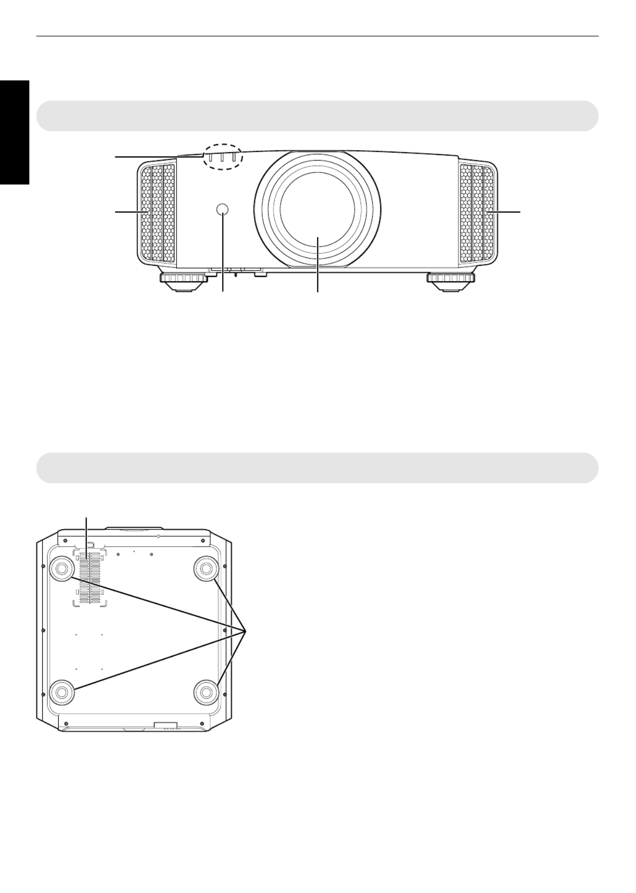
Controls Featuresand
Main Unit Front
AB
C
D D
A
A
A
AA Lens
This is a projection lens. Do look lensnot throughthe
whileanimage is projected.
B
B
B
BB Remote (front)Sensor
Pleaseaimtheremotecontrolatthisareawhenusing
it.
* There is also a remote sensor at the rear.
C
C
C
CC Indicator
Refer Display onto “Indicator the 79).MainUnit” (p.
D
D
D
DD Exhaust vent
Warm toairis discharged cool down theinternal
temperature.
Donot block thevents.
Main Unit Bottom
E
E
E
EE Inlets the(at 3 pointson rear/bottom)
The take inlets inairto cool down the internal temperature.
Do maynot hot block or of prevent the outflow air. Doing so cause
theunit to malfunction.
* There are two inlets on andtheright left sides rear atthe oftheunit.
F
F
F
FF Feet
Theheightandangleoftheprojectorcanbeadjustedbyturningthe
foot. (0 5 to mm)(p.21)
Whenthefootis removed, it can beusedasthemountingholesfor
theceilingmount bracket.
E
F
14
GettingStarted

Main Unit Rear
E
G IJK
E
H
G
G
G
GG Inputterminals
In theadditionto video alsoinput there terminal, are
other for devicesconnectionterminals suchas
controllers equipment.andoptional
Please “Main 16see Unit Input Terminals”p. for
more about terminals.details the
H
H
H
HH Lampcover
When lamp, remove replacing the source light this
cover.
I
I
I
II Operationpanel
For themore todetails, please refer “Operation
panel” diagram below.inthe
J
J
J
JJ RemoteSensor(rear)
Pleaseaimtheremotecontrolatthisareawhenusing
it.
* There is also a remote sensor at the front.
K
K
K
KK Powerinputterminal
Connect tothe cordsupplied power this terminal.
Operationpanel
[MENU]: Displays the menu [BACK]: Returns to the previous menu
[JKH I] keys: Selects an item
[OK]: Confirms a selection
[INPUT]: Switches the input
A [STANDBY/ON]: Turns “on”/“off” the
power
15
GettingStarted
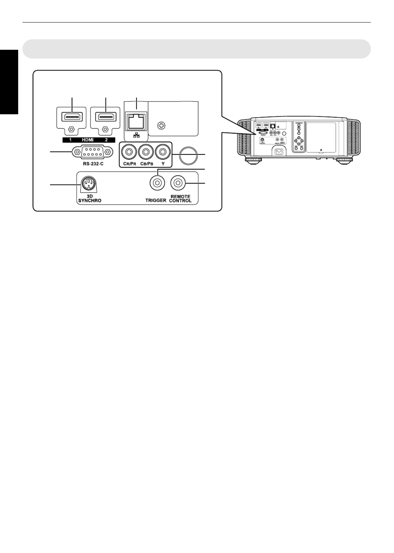
Main Unit Terminals Input
A B C
D
E
F
H
G
Enlarged View of Rear Face
A
A
A
AA [HDMI1] input terminal
B
B
B
BB [HDMI2] input terminal
Forconnecting to support output. devices that HDMI
(p.22)
It the theis fitted to M3 hole. The oflock depth screw
hole mm.is 3
C
C
C
CC [LAN] terminal (RJ45)
The projector can be controlled by connecting to it a
PCthrough the control computer network for
commandstobesenttotheprojector.
D
D
D
DD [RS pin232C] terminal (D sub 9
male)
Theprojector can becontrolledbyconnectingaPCto
this terminal.
* TheLANandRS232Cterminalscannotbeusedatthe
same time. (p.60)
E
E
E
EE [3DSYNCHRO]terminal
By connecting a 3D EMITTER (sold SYNCHRO
separately) terminal, you movies.to this can view 3D
F
F
F
FF Component inputvideo terminals
(RCA x 3)
Forconnecting to support devices that component
signaloutput.
It can beusedasaninputterminalforanalogRGB(G
on (Y, or formatSync), component Cb, Cr), DTV (Y,
Pb,Pr) signals.
G
G
G
GG [TRIGGER] terminal ( )
Output Itterminal mA power for DC 10012V, supply.
isused for sending output signalsto control elevating
screens which use for the of a SCREEN TRIGGER is
supported.
Note improperthat connectionmaydamagethe
projector.(Tip=DC +12 Sleeve=GND) V,
H
H
H
HH [REMOTE] terminal (stereo mini
jack)
Use control unit not this terminal when a remote is
usable, when installedsuchas the projector is ina
dedicated box for projection. or rear
Connect unit toanexternal remote sensor the
projectorunit.
For thedetails on external and infrared sensor
connecting contactcable, please your dealer.
16
GettingStarted
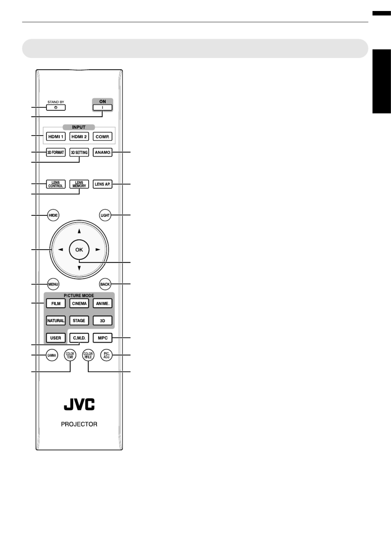
Remote Control
A
A
A
AA B
B
B
BB
[STANDBY]
Turns power. off the (p.27)
B
B
B
BB C
C
C
CC
[ON]
Turns power. (p.onthe 26)
C
C
C
CC [INPUT]
Selectaninput from [HDMI 1],
[HDMI 2], [COMP.]. and (p.26)
D
D
D
DD [3DFORMAT]
Switches format. (p.the3D 35)
E
E
E
EE [3DSETTING]
Displaysthe3D setting menu.
(p.35)
F
F
F
FF
[ANAMO.]
Switches anamorphicthe mode.
(p.55)
G
G
G
GG [LENSCONTROL]
For focus, adjusting zoom, and
shift.(p.28)
H
H
H
HH [LENS MEMORY]
Switchesbetweensaving,
retrieving,andeditingofthelens
memory. (p. 29)
I
I
I
II
[LENSAP.]
For thesetting lens aperture.
(p.50)
J
J
J
JJ [HIDE]
Hidestheimagetemporarily.
(p.26)
K
K
K
KK [LIGHT]
Illuminates onthebuttons the
remote control.
L
L
L
LL [ ]
JKH
JKH
JKH
JKHJKH I
I
I
II
keys
For selecting anitem.
M
M
M
MM [OK]
Confirms a selecteditem.
N
N
N
NN [MENU]
Displaysthemenu,
or hides the menu if it is
displayed.
O
O
O
OO [BACK]
Returns to menu. the previous
P
P
P
PP [PICTUREMODE]
Switches Picture modethe to
[FILM], [CINEMA], [ANIME],
[NATURAL], [STAGE], [3D], or
[USER].(p.37)
Q
Q
Q
QQ [C.M.D.]
Forsetting frame interpolation.
(p.44)
R
R
R
RR [MPC]
For thesetting MPClevel.
(p.39)
S
S
S
SS [GAMMA]
For thesetting gammalevel.
(p.40)
T
T
T
TT [COLORTEMP]
For setting thecolor
temperature.(p.47)
U
U
U
UU
[COLOR P.FILE]
Switches colorthe profile.
(p.38)
V
V
V
VV [PIC.ADJ.]
Switches for adjustingtheitems
the suchimagequality, as
contrast, etc. brightness,
(p.48)
A
C
D
G
J
N
P
S
L
B
E
H
Q
T
M
K
I
F
O
V
R
U
17
GettingStarted

Loading the Remote Control Batteries into
Iftheremotecontrolhastobebroughtclosertotheprojectortooperate,itmeans that thebatteriesarewearingout.
Replace with new (AAA).thebatteries ones
Insert according to Be to insert first.thebatteries the t smarks. sure the send
If occurs the the theanerror while using remote control, remove batteries and five wait for minutes. Load batteries
againand operate the remote control.
Effective UnitRangeofRemoteControl
Whenaimingtheremotecontroltowardthesensoronthis
unit (front orrear),ensurethatthedistancetothesensor
iswithin m. 7
If the remote control tofails work properly, move closer
to unit. this
30°
30°
20°
20°
Remote Control
This unit
Control etc. through reflection off a screen,
Ensurethatthetotalofdistance A (betweenthisunitand
the thescreen) distanceand B (between remote control
and within m.thescreen)is 7
* As the efficiency of signals reflected from the remote
control type unit varies with the of screen used, the
operabledistancemaydecrease.
A
B
30°
30°
20°
20°
20°
20°
20°
20°
20°
20°
20°
20°
20°
20°
Screen
Remote Control
This unit
CAUTION
Do innot put control the remote a place with anexposure to direct sun light or high temperature.
18
GettingStarted

InstallingtheProjector
Precautions Installation during
Pleaseread installingthe following carefully before this
unit.
Do the followingnot install at
This is Pleaseunit a precision device. refrain from
installingorusingitatthefollowinglocations.Otherwise,
it may cause fire ormalfunction.
Dusty, humidwetand places
Places oily subject to smoke or smoke cigarette
On top of or or a carpet bedding, other soft surfaces
Placesexposedto direct sunlight
Places low with a high or temperature
Do in is oilynot unitinstall this a room that orsubject
tocigarettesmoke.Evenasmallquantityofsmokeor
oiliness have on can a long term impact this unit.
* This unit produces a great amount of heat, and is
designed take itsto in cool airto cool optical
components.Usingtheunitattheabovelocationsmay
cause to to path, therebydirt attach the light resulting
in imagesdark ordullcolors.
* Dirt sticks opticalthat tothe componentscannotbe
removed.
Maintain clearance from etc. thewall,
As unit discharges a amountthe large ofheat,installit
withadequateclearancefromthesurroundingsasshown
below.
Front
150 mm
and above
200 mm
and above
300 mm
and above
300 mm
and above
150 mm and above
Leavethe thefrontarea of unit unblocked.
Ifthere obstructing front theisany object in of exhaust
vent,hotairwillflow andback to unit the cause toit heat
up.Hotair flowing out oftheunitmaycause shadows on
the screen (heat haze phenomenon).
Usingtheprojector
Thisunitusesaprojectionlamp,whichwillheatupwhen
inuse.
Please in refrain from projecting thefollowing
circumstances. cause fire Otherwise, it may or
malfunction.
Projection vertically with theunit stood
Projection angle with theunit inclined at an
Horizontal within inclination: ± 5 °
5° 5°
Vertical inclination: ± ° within 15
15°
15°
15°
15°
Malfunctionmayoccuriftheangleisnotsetwithinthe
abovementioned range.
Installingthescreen
Install screen they aretheunitandthe suchthat
perpendicular eachto other.
Screen
Front
Pleasechoose non uniform a screen material with
patterns.Uniformpatternssuchaschecksmaycause
interference to patterns occur.
In this case,you can change thesizeofthe screen to
make less noticeable.theinterference patterns
Using atheprojectorat highaltitude
When location that higher than using this unit at a is 900
m pressure),abovesealevel(lowair setthe“High
Altitude to “On”. (p.Mode” 60)
19
Set up

Precautions Mounting during
Securing the(mounting) projector
When this unitisto be mounted ato fixed position for
use, install horizontally. it
Makesure secure theto mainunit to prevent
accidents duringsuchas anearthquake.
Securingwithscrews
Air Inlets
4 Locations
Removethefourfeetatthe bottom, and fasten usingthe
screws (M5 screws,13to23mm).
* Using screws other than those designated may cause
theunit to down. break
* Leave a clearance of least 10 mmat fromthebottom
surface to to of the unit allow it takeincool air.
Securing the projector (ceiling mount)
Special and expertise techniques are required for
mounting this unittotheceiling.Makesurethatyou
get dealerthe authorized or specialist install it. ato
Take mainthe the necessary actions to prevent unit
from duringfalling off suchas anearthquake.
Regardless warranty period,ofthe JVCisnotliable
foranyproductdamagecausedbymounting unitthe
withnonJVCceilingfittingsortoanenvironmentthat
isnot mount.suited ceiling for
When ceiling, using theunit from with it suspended a
pay When attention to surroundingthe temperature.
a temperatureheaterisinuse,the aroundtheceiling
maybehigher than expected.
20
Set up

Adjusting Positionthe
Adjustingtheelevationangleoftheprojector
The and of mm)height inclination the unit (0 to 5 can be
adjustedbyturningthefeet.
Lift and feet.the unit adjust thefour
ContractExtend
Feet
Adjusting imagethe the position of
By using unit, thelens of shift feature this you can shift
the theimageupward/downward toor left/right. Set it to
your position.preferred
90
80
70
60
50
40
30
20
10
0 10 3020 40
Lens movement range
Horizontal lens shift (%)
Vertical lens shift (%)
Lens shift Range
Up to about 80% of the
projected image
Horizontal Position: 0 % (Center)
Vertical Position
Up to about 34% of the
projected image
Vertical Position: 0% (Center)
Horizontal Position
■
■
■
The maximum vertical varies of shift with the amount
horizontal horizontalshift.Similarly,themaximum
shift changes with amountalso the ofverticalshift.
Thevaluesonthegraphare intended as a guide.Use
them for referenceduringinstallation.
21
Set up

ConnectingtheProjector
Do isnot connectionturn theon power until complete.
The details, please manualconnection procedures according to device For differ the used. refer to instructionthe
ofthedevice to connected. be
This is images. projector used for projecting Tooutputthe connect audio of please connected devices, a separate
audio device, speaker.output suchasanamplifieror
The displayed on and cablesimages may not be depending the devices to connected. be
Useonly HDMI cables (sold separately) that HDMI are certified.
Some cables of cannot be to unit to connected this due thesize their connector cover.
Connecting the Input)to HDMIInputTerminal (Digital
Connectingvia HDMI cable
HDMI Output Terminal
BD/DVD Recorder, etc.
Laptop, etc.
HDMI Cable (Sold Separately)
This Unit
To [HDMI 1] or [HDMI 2] input
terminal
If occurs, the noise move laptopawayfrom unit. this
For the a transmission bandwidth in compliance with HDMI MHz Whenstandard, a 340 cable is recommended.
usingacablewithabandwidthof75MHz,youarerecommendedtosettheresolutionofthe equipment transmitting
thevideo orto1080i lower.
If the try reduce the the the the videoisnot displayed, to length of cable orlower resolution of videotransmitting
equipment.
Connecting DVIvia HDMI conversion cable
HDMI-DVI Conversion Cable (Sold Separately)
To [HDMI 1] or [HDMI 2] input
terminal
This Unit
DVI Output Terminal
Desktop PC, etc.
If occurs, the noise move desktop PCawayfrom unit. this
If the try reduce the the the the videoisnot displayed, to length of cable orlower resolution of videotransmitting
equipment.
22
Set up

ConnectingtotheComponentVideoInputTerminal(AnalogInput)
Connecting componentvia videocable
Y
CR/ PR
CB/ PB
(Green)
(Blue)
(Red)
Component Video Output Terminals
BD/DVD Recorder, etc.
Component Video Cable (Sold Separately)
To component video
input terminals
This Unit
Set in 51)“COMP.” Pb/Cbto “Y Pr/Cr” thesetting menu. (p.
Connectingvia videoRGB cable
R
B
G
(Green) (Includes Sync Signal)
(Blue)
(Red)
RGB Video Output Terminals
Device Equipped with RGB
Output, etc.
RGB Video Cable (Sold Separately)
To RGB Video Input
Terminals
This Unit
Set in 51)“COMP.”to“RGB” the setting menu.(p.
For more information on compatible signals, please input refer to “Specifications”p. 74.
23
Set up

Connecting theto LANTerminal
Desktop PC, etc. Server
Hub
Network
Connection Cable
(Sold Separately)
This Unit
To [LAN] Terminal
The used used or video signals. network is to control unit. not this Itis for sending receiving
Pleasecontact concerning connection. your network administrator for information the network
Set if is is in “ECO Mode”to“Off” RS232C/LAN communication performed or HDMI linkthe function used the
Standbymode.(p.60)
Formore to (p. information on please control, refer “External Control” 70).
Connecting the 232Cto RS Terminal
RS-232C Terminal
Laptop, etc.
RS-232C Connection Cable (Sold Separately)
To [RS-232C] Terminal
This Unit
Set if is is in “ECO Mode”to “Off” RS232C/LAN communication performed or HDMI linkthe function used the
Standby (p.mode. 60)
For 70).more to (p. information on please control, refer “External Control”
Connecting the REMOTEto Terminal
External Infrared Sensor
(Sold Separately)
Connection Cable
(Sold Separately)
To [REMOTE] Terminal
This Unit
For the more information on external and cable, please dealer. infrared sensor connecting contact your
24
Set up

Connecting theto TRIGGERTerminal
Trigger Input Terminal (Ø3.5)
Screen
Trigger Cable (Sold Separately)
To [TRIGGER] Terminal
This Unit
Do itnot use to to supply power other devices.
Connecting audio another cause malfunction breaktothe terminalof devicemay thedeviceto or down.
Using cause unit to beyond the rated valuewill the malfunction.
The terminal voltage of 12 trigger outputs a V. Exercise adequate caution to short circuit. prevent
The item 60).factory setting “Off”. configure is To change the setting, the “Trigger” inthe menu (p.
Connecting the (Supplied PowerCord Accessory)
AConnectthepower suppliedcord tothepower terminalinput on
themainunit
BInsert plug intothesupplied power thewalloutlet.
Precautions prevent electricto fireand shock
The voltage of large. capacity this unit is Please it wallconnect directly tothe outlet.
When you please power are not using the equipment, unplugthe cord thefrom outlet.
Connectit using only powerthe cordsupplied.
Donotuse the a voltage than other indicated power voltage.
Do Do heatnotdamage, or power break modify the cord. not place a heavy on power or object the cord, or it. pull
Doing damage power so may the cord.
Do wetnot unplug the cordpower with hands.
A
B
Power Cord
(Supplied)
25
Set up

Turn off thepower
Remote control: [STAND presstheBBY]button
Projectorunit: press button the A[STANDBY/ON]
While you you message again.the“Are sure want toturn off?” is displayed, press buttonthe
The and greenlampturnsoff, the “STANDBY/ON” indicator switches from a light to red a blinking light.
After light for about cool down downthe goesoff,thefanwillrun 60secondsto thelamp(Cool mode)
Do is innot disconnect the power while cable cooling progress.
After about “STANDBY/ON” indicator switches from a blinking a light. 60seconds,the redto solidred
LAMP WARNINGSTANDBY/ON LAMP WARNINGSTANDBY/ON
ND
TAN
DBY
In standby state
“STANDBY/ON” lights up (red)
In the Cool-down mode
“STANDBY/ON” blinking (red)
Attach cover.thelens
CAUTION
The power within approximately after has been cannot be turned off 90seconds it turned on.
After light for about cool down down mode)the goesoff,thefanwillrun 60secondsto thelamp(Cool
Do is innot disconnect the power while cable cooling progress.
The power while (60 cannot be turned on again cooling is in progress seconds).
Pull isout plug unitthepower whenthe not to be used of time. for a prolonged period
27
Operate
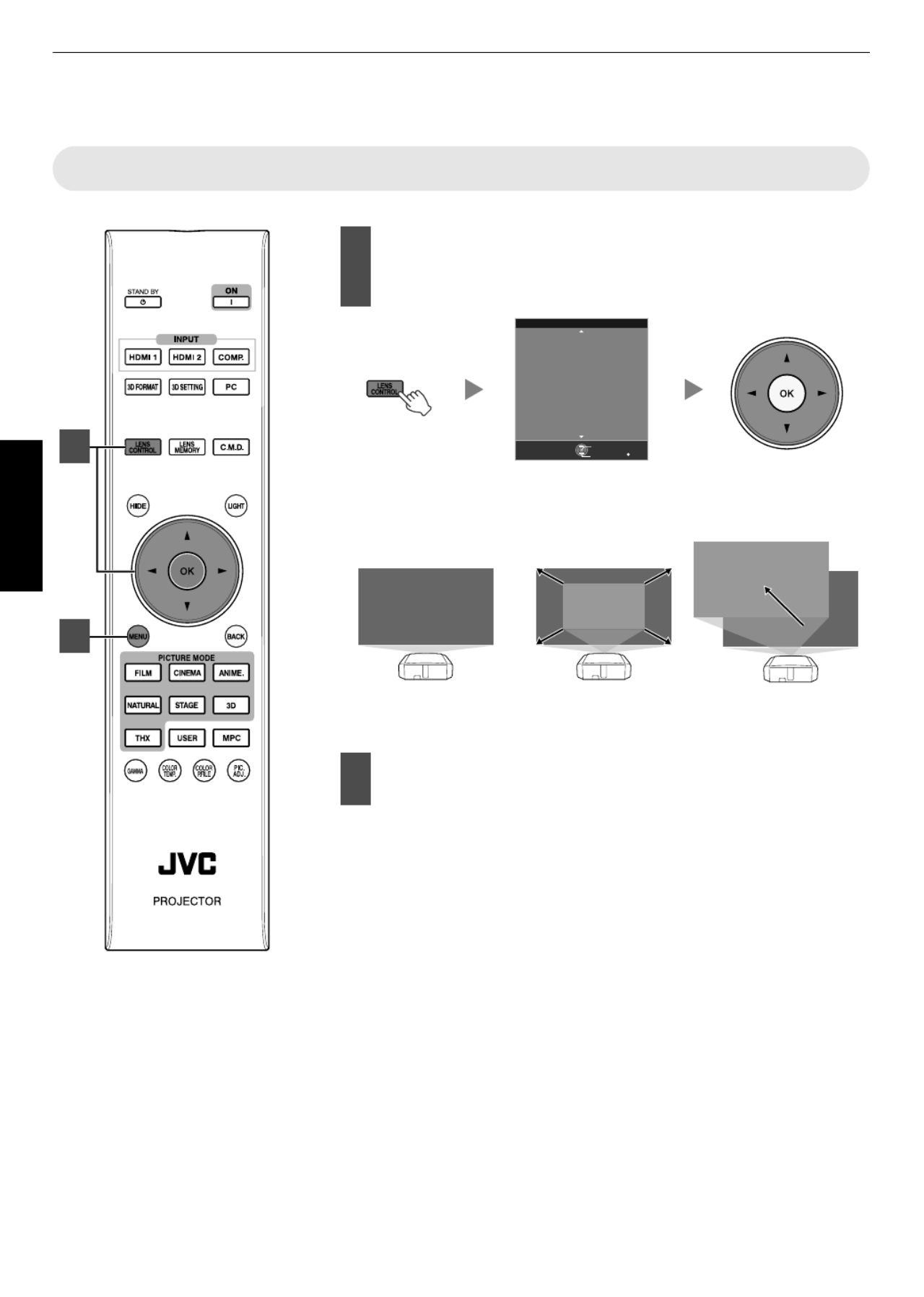
Adjusting ScreentheProjector
Adjusting According to PositiontheLens the Projection
Press CONTROL] andthe [LENS button, usethe
[ ] adjust (screenJKH Ikeysto Focus,Zoom size),
and Shift (screen position)
BACK
Back
Select
Operate
Focus
Lens Control
Pressing or each switchesthe[LENSCONTROL] [OK]button time
the the mode in following sequence: “Focus”“Zoom”“Shift”
“Focus”...
Shift (Screen Position)
Adjustment
Zoom (Screen Size)
Adjustment
ABCD
ABCD
ABCD
Focus Adjustment
Press or twice,the[BACK] button once, the[MENU]
to end adjustment.
1
2
28
Operate

SavingandRetrievingAdjustmentSettings
The zoom, and saved or youfocus, shift be settings can retrieved, so can
switch to differenteasily aaspect ratio (screen size)accordingtotheimage.
Pressingthe[LENSMEMORY]buttoneachtimeswitchesthemodeinthe
followingsequence:“LensMemorySave”“LensMemorySelect”“Lens
Memory Memory Save”...NameEdit”“Lens
In no a state where adjustment settings are saved(factory default), only
“Lens Memory Save” is displayed.
Savingan adjustment data
Adjust shiftfocus,zoom,or (p.28)
Press display “Lensthe [LENS MEMORY] button to
MemorySave”
MENU BACK
-----
-----
-----
-----
-----
-----
-----
-----
-----
>>
-----
Back
Operate
Select
Exit
Lens Memory Save
Installation
You also save can an adjustment data by selecting “Installation”
“LensControl” “Lens Memory Save” from the menu.
Select item andthe tosave, press buttonthe [OK]
The adjustment data issaved.
Items with adjustment data are [ no saved displayedas ].
Ifyouhaveselectedanitemforwhichanadjustmentdatahasalready
been saved, theold will data beoverwritten.
You name when item. can changethe saving an (p.30)
The maximum of items number can besaved is 5.
Pressthe[MENU] button to exit
2
4
3
29
Operate

Retrievingan adjustment data
Press display “Lensthe [LENS MEMORY] button to Memory Select”
MENU BACK
-----
-----
-----
MEMORY2
-----
-----
-----
-----
-----
>>
MEMORY1
Back
Operate
Select
Exit
Lens Memory Select
Installation
You also “Lens “Lens Select” can retrieve an adjustment data by selecting “Installation”Control” Memory
from menu.the
Select andthe adjustment data to retrieve, press the [OK] button
The automatically. retrieved data is adjusted
If no the adjustment data has been saved, item grayed andwillbe out cannot be selected.
Renamingan adjustment data
Press display Namethe [LENS MEMORY] button to “Lens Memory Edit”
You also edit “Lens “Lens Name can an adjustment data by selecting “Installation”Control” Memory Edit”
from menu.the
MENU BACK
-----
-----
-----
MEMORY2
-----
-----
-----
-----
-----
>>
MEMORY1
Back
Operate
Select
Exit
Installation
Lens Memory Name Edit
Select andthe adjustment data to edit, press buttonthe [OK]
An screen appears.edit
>>
MENU BACK
SPACE
User 1
\}{][><
)(
~
|
;:
?=/-+*&%$#"!
^.,0987654321
zyxwvytsrqpon
lkjihgfedcba
YXWVUTSRQPON
MLKJIHGFEDCB
Z
m
@
A
Character List
Selection Cursor Input Cursor
Back
Operate
Select
Exit
Installation
OKAll ClearClear
User Name Edit
You 10 can input up to characters.
Characters include characters,that usable are alphabets or (upper lower case), numeric and symbols.
Pressing cancels being edited,the[Back]button thecontentthatiscurrently andexitstheeditmode.
After renaming, select“OK”andpressthe[OK]button
Pressthe[MENU] button to exit
30
Operate

Adjusting According to Image Quality Automatically theViewing
Environment
By configuring according to “Environment Setting” the
viewing quality and environment, image adjustment
correction according to environmental differences are
performedautomaticallytominimizeanyinfluenceonthe
imagequality.
“Environment Setting” isappliedseparatelyfromthe
individual adjustment settingsimage (p.47).
Projector
Viewer
Viewing
Distance
Screen Size
Screen
- Front View -
Press displaythe[MENU] button to
themenu
Select“Installation”“Environment
Setting” menu“On”fromthe
>>
MENU BACK
0
MENU BACK
BackOperate
Select
Exit BackOperate
Select
Exit
Installation Installation
Screen Adjust
Anamorphic
Pincushion
Keystone
Front
Installation Style
Pixel Adjust
Lens Control
100inch
Light
3.0H
On
On
Off
Off
Viewing Distance
Screen Size
Wall Color
Environment Setting
Environment Setting
Environment Setting
When set “Environment Setting” is to “Off”,
“Screen “Viewing Distance”,Size”, and“Wall
Color” are selected. grayedoutandcannotbe
Select “Screen Size”to configure the
screensizetouse
Selectthe the closest screen size setting from
range “60inch” “200inch”between and (in10
inchincrements).
Select Distance” “Viewing to
configure distancetheviewing
(distancetothescreen)
Selecttheclosestviewingdistance setting from
the range between m” and “10 m”. “1
For the more details on height, please refer to
“Screen Distance”p.SizeandProjection 75.
Select“Wall Color” to configure the
wallcolor
If the wall is in black color, Forselect “Dark”.
wallswitha color otherthanblack,select“Light”
.
Pressthe[MENU] button to exit
31
Operate

Setting Screen Correction
Byselectingtheoptimalcorrectionmodeaccordingtothe
characteristics corrections beof use,the screen in can
performed natural withtoreproduce images balanced
colors.
Thisfunctionisdisactivatedwhen“ColorProfile”isset
to “Off”.
Press displaythe[MENU] button to
themenu
Select “Installation” “ScreenAdjust”
“On” from the menu
MENU BACK
0
MENU BACK
0
Back
Operate
Select
Exit Back
Operate
Select
Exit
Environment Correction
Installation
Anamorphic
Pincushion
Keystone
Front
Installation Style
Pixel Adjust
Lens Control
Screen Adjust
Environment Correction
Installation
Anamorphic
Pincushion
Keyst one
Front
Installation Style
Pixel Adjust
Lens Control
Screen Adjust
A
B
C
On
Off Off
Off
Select or “C”one from three the types (“A”, “B”,
).
For the the information on screen and
correspondingcorrectionmode, please visitour
website.
http://www3.jvckenwood.com/english/projector/
screen/
Pressthe[MENU] button to exit
32
Operate

Adjustingthe Screen Size(Aspect)
The of adjusted screen size the projected image can be
optimally originalaccording to the screen size(aspect)
that has been input.
Press displaythe[MENU] button to
themenu
Select Signal”“Input“Aspect
(Video)” “Aspector (PC)”fromthe
menu
MENU BACK
3D Setting
AutoProgressive
OffMask
16:9Aspect (Video)
Picture Position
PC
COMP.
HDMI
Input Signal
Back
Operate
Select
Exit
InputSignal Setting Description
Aspect
(Video)
4:3 Setsthescreensizeto4:3.For
HD two aresignals,the sides
reduced.
16:9 Sets 16:9.the screen sizeto
For theSD signals, two sides
are expanded.
Zoom Enlargestheentireimage.
*Not selectable inthe
case HDof signals.
Aspect(PC) Auto Positionstheimageatthe
center with theentireimage
enlarged.
Just Displaystheinputimageinthe
actualsize.
Full Fills screen withtheentire the
imagewiththesize(aspect)of
theinput ignored.image
During3Dsignalinput,thesize is fixedat“16:9”
.
Pressthe[MENU] button to exit
Example screenofinputimageand size
HDMI videoinput,component input
Zoom16:94:3
4:3
2.35:1
(Cinema
Scope)
Setting
Input Image
Output Image
PCInput
1280×1024
1920×1200
FullJustAuto
Setting
Output Image
Input Image
33
Operate
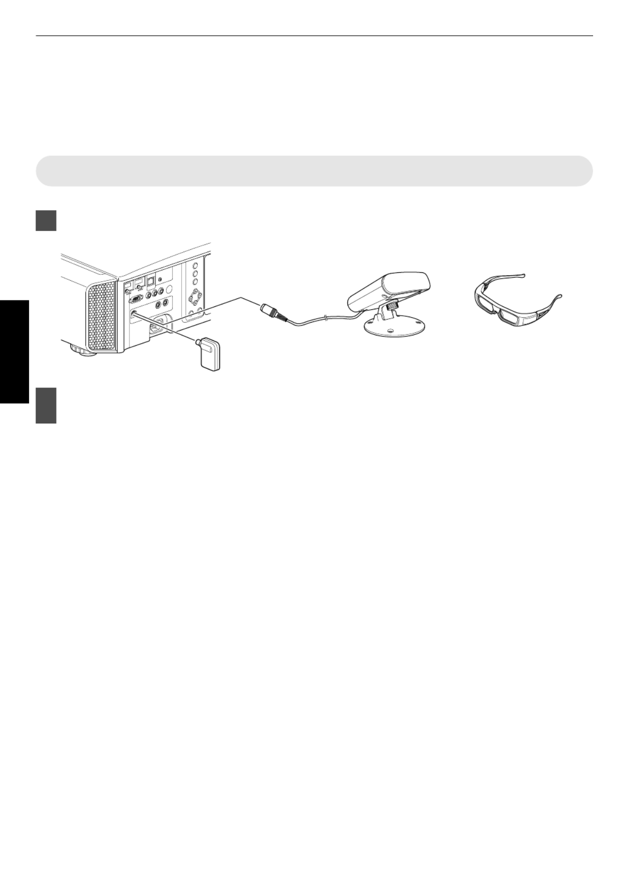
Viewing 3D Movies
By using the3DGLASSES AG1,(PK PKAG2,or AG3)PK and 3D SYNCHROEMITTER(PK EM1 orPKEM2),both
sold separately, you enjoy video can 3D images.
For3D GLASSES and 3D EMITTER that compatible please SYNCHRO are with this unit, refer to“Optional
Accessories”p.11.
Installing the 3D SYNCHRO EMITTER
Connect to unit3D EMITTER SYNCHRO the the [3D SYNCHRO] terminal on main
3D GLASSES
3D SYNCHRO EMITTER
PK-EM2
PK-EM1
3D SYNCHRO EMITTER
This Unit
Adjust SYNCHRO so GLASSES can receivethe3D EMITTERposition thatthe3D
signals EMITTERfromthe3D SYNCHRO
For themore todetails, please refer instructionmanuals GLASSES and 3D3D SYNCHRO EMITTER.
34
Operate

Viewing3DMovies
Connect unit to this a 3D compatible
HDMI and on power device, turn the
to backplay the3D imagevideo
Fordetailsonhowtoplayback3Dvideoimages,
please manual of refer to instructionthe the
player inorrecorder use.
When signals3D are received, thevideoimage
switches format.automaticallytothe3D
This unit supportsthe following 3Dformats.
Frame packing
Side by side
Top and bottom
Inthedefaultsetting,“3DFormat”issetto“Auto”
for projectionautomatic of3Dimages.
If the imagedoes 3D automaticallynot switch to
Press onthe [3D FORMAT] button theremote
control
Pressing [3D FORMAT] eachthe button time
switches mode following sequence:the inthe
“Auto” “Side Bottom”bySide”“Topand
“2D” “Auto”...
Format Description
Auto The detectedformatis and
configuredautomatically.
Side Side Select thisby settingifthe3Dinput
signal ofis theside by side
format.
Topand Bottom Select this setting if 3Dthe input
signal of andis the top bottom
format.
2D Select 2D this setting if images
are recognizedfalsely as3D
ones.
Turnofthepowerofthe3DGLASSES
and onput them
The on automatically.PK AG1 powers
Converting Movies Movies2D to3D forViewing
Press SETTING]the [3D button to
display “3D Setting”
>
MENU BACK
1
0
0
Input Signal
BackOperate
Select
Exit
Sub Title Adjust
Intensity
Crosstalk Cancel
Parallax
Off
Off
2D to 3D conversion
Auto
3D Format
3D Setting
Select“2Dto3Dconversion”followed
by “On”, press button and the [OK]
Pressthe[MENU] button to exit
MEMO
Dependingonthemovies, 3D effectmaybeless than
what you expected.
35
Operate

Adjusting3DMovies
3D images may appearvideo differently to different
viewers. alsoItmay be affected by your physical
conditionatthetimeofviewing.
You video are therefore to recommended adjust the
imagesaccordingly.
Press SETTING]the [3D button to
display “3D Setting”
Adjusting parallax (Parallax)
Adjust displacement forthe oftheimage theleft
and separately obtain 3Drighteyes to the best
effect.
Todo use the the cursor.so, H Ikeys moveto
Setting +15range:15to
Adjusting crosstalk (Crosstalk Cancel)
Double of leftimages (overlapping the imagewith
the theoneon right vice be reducedor versa) can
todeliver clear quality. a
Todo the the cursor.so,use H Ikeys moveto
Setting 8range: to+8
* Adjustment madecannotbe when“2Dto3D
conversion”issetto“On”.
Adjustthe (Intensity)depth perception
The of adjusted deliverdepth theimage can be to
thebest3Deffectduring2D 3D imageconversion.
Todo the the cursor.so,use H Ikeys moveto
Setting 1 5range: to
* Adjustment can made onlybe when“2Dto3D
conversion”issetto“On”.
MEMO
Dependingonthemovies,3Deffectmaybelessthan
what you expected.
Adjusting subtitle displaythe (SubTitle
Adjust)
If occurs the distortion in subtitle during2D 3D
image conversion, setto “On”.
* Adjustment can made onlybe when“2Dto3D
conversion”issetto“On”.
Pressthe[MENU] button to exit
36
Operate

Settingthe Color Profile
By setting according to the“Color Profile” (color space information) the “Picture Mode”, you
can arefinetunetheimagequalityaccordingtothemovieyou viewing.
After 37),configuring“PictureMode”(p. pressthe[COLOR
P.FILE]button
Pressing each time switches forthe[COLORP.FILE]button the“ColorProfile”data
the“Picture Mode” insequence.
List Profile”of“Color for“PictureMode”
Picture Mode Color Profile Description
Film Film Color that suitable movies.space is for all
Standard ColorspaceoftheHDTV*standard.
Cinema Cinema Color that suitablespace is for movies vivid with colors.
Standard ColorspaceoftheHDTV*standard.
Animation Anime Color that suitable animatedspace is for works.
Standard ColorspaceoftheHDTV*standard.
Natural Natural Color that suitable footage,space is for drama etc.
Standard ColorspaceoftheHDTV*standard.
Stage Stage Color that suitablespace is for concerts, etc. theatrical performances,
Standard ColorspaceoftheHDTV*standard.
3D 3D Color isspacethat suitable 3D movies. for
Standard ColorspaceoftheHDTV*standard.
User User 1 to 5 Stage When set of 5”, you “Picture Mode” is to any the to settings from “User 1” “User can
select color shown left.oneofthe profiles onthe
Seeabove for the the description of respective color profiles.
Standard
Cinema
Anime
Natural
Stage
3D
Off Disables color space adjustment.
* HDTV is the abbreviation for High Definition Television.
38
Adjust/Set

Adjusting for IncreasedMovies
Expressiveness (Multiple Control) Pixel
ThenewimageprocessingalgorithmdevelopedbyJVC
helps create a natural sharperto impressionthatis at
areas and areas thatinfocus, softer at are not focus,in
enabling you enjoy highly to expressive 4K images with
a sensegreater ofdepth.
Press [MPC] displaythe button to the
adjustment menu
>>
MENU BACK
50
50
50
Back
Operate
Select
Exit
Smoothing
Dynamic Contrast
Enhance
FILM4K Profile
MPC Level
Picture Adjust
Select“4KProfile”andpressthe[OK]
button to content type selectthe you
areviewing
ContentType Description
FILM Forviewing on Blumovies ray disc
produced using films
High viewing Blu Disc Resolution For ray works
HD Forviewing andTV broadcasting
recordedworks
SD For DVD worksviewing
Dynamic For enhanced effects
Off For displaying intheoriginal
resolution (2K)
* HD is the abbreviation for High Definition.
* SD is the abbreviation for Standard Definition.
Select“SD”whenviewingworksbroadcastedin
theSD quality.image
Pressthe[MENU] button to exit
Fine tuning
After selecting a type, adjust content “Enhance”,
“Dynamic and Contrast”, “Smoothing” according to your
preference.
Item Setting
Range Description
Enhance 0to the 100 Enhances sharpness of
theimage.
Dynamic
Contrast
0 100 Enhancesto thecontrastofthe
image.
Smoothing 0 100 Enhancesto theblurrinessofthe
image for a softer effect.
By expect increasing the setting range, you can
enhanced effects.
Images displayed original are inthe resolution (2K)
when “4K Profile” set is to “Off”.
“Enhance”,“DynamicContrast”,and“Smoothing”can
be to “Off”. adjusted even iswhen “4K Profile” set
* MPC is the abbreviation for Multiple Pixel Control.
Abouttheanalysisscreen
By press the[MPC]buttonwhiletheadjustment menu in
thestep1isonscreen,theanalysis screen isdisplayed.
In the analysisscreen,parts where theeffectappearare
highlightedincolorswhen“Enhance”,“Dynamic
Contrast”, “Smoothing” are adjusted.and
>>
MENU BACK
50
50
50
BackOperate
Select
Exit
Smoothing
Dynamic Contrast
Enhance
FILM4K Profile
MPC Level
Picture Adjust
Analysis screen
Adjustment menu display
Highlighted color Adjustment resulting ineffects
Blue,green Enhance
Red,yellow DynamicContrast
Black Smoothing
Todisplay any ofthe adjustment menu, operate the
keys while analysis the screen isdisplayed.
Noadjustmentcanbemadewhiletheanalysisscreen
is displayed. Make after adjustments returning to the
adjustmentscreen.
39
Adjust/Set

Fine thetuning Image Quality
Adjustingthe Output (Gamma) Value theof Projected Image
You value of video signal can adjust theoutput the the projected image with respect to input.
Example adjustmentofgamma
The overall original areas visible. image appear brighter with respect to the image, making thedark more
0
255
0 255
The photos are for illustrative purposes only.
Input Value
Output Value
Increases with creating a sensethecontrast respecttotheoriginalimage, greater ofdepth.
0
255
0 255
The photos are for illustrative purposes only.
Input Value
Output Value
Pressthe [GAMMA] button
Pressing [GAMMA] each switches setting sequence.the button time the in
* The setting value varies with the model in use, as well as the input signal and
Picturemode.
Gamma settings adjustment
Setting InputSignal Description
Normal normal viewing.2D, 3D Recommended setting for
A Places more emphasis on the gradation compared to the “Normal”
setting.
B Image is with a sense of thatdepth characteristic of films.
C Image iscontrast enhanced compared to “B”the setting.
D Image with brighter midtones compared tothe“Normal”setting.
E Recommended setting whenviewing3Dmovies.
F The overall image is brighter than that in the “E” setting.
G Recommended setting whenviewing3DTV,drama,andsports.
H The overall image is brighter than that in the “G” setting.
Custom 1 Custom 3 2D Adjustable a setting. to to preferredgamma (p.41)
During input to to cannot be3D signal and when Mode” set “Picture is “3D”, Custom 1 Custom 3 selected.
40
Adjust/Set

Aboutgammaadjustment
When gamma line:the curveis a straight
The and of video brightness contrast the input bewill
the thesame that ofas videooutput.
Area for straight whichthegammacurveisabovethe
line(A):
Video brighteroutputappears thantheinput.
Area for straight whichthegammacurveisbelowthe
line(B):
Video darkeroutputappears thantheinput.
Area for whichtheslopeofthegammacurveissteep
(midtone) (C):
The grayscale of video range the outputbecomes
wider, contrastandthe increases (DD’).
C
B
A
D
0 255
0
255
D”
Gamma Curve
Input Value
Output Value
Dark
Dark
Bright
Bright
CompensatingHighlightsand Shadows (Dark/Bright Level)
You adjust quality can theimage to sharpproduce a
contrastinthebrightness.
Press displaythe[MENU] button to
themenu
Select“Picture Adjust”“Dark/Bright
Level”fromthemenu
Shadowcorrection
Adjusts inputthe the shadows of video (thewhite,
red, be green, and blue tones can adjusted
separately).
Todo the the cursor.so,use H Ikeys moveto
Setting 7 shadows)range: (darkensthe to+7
(brightens shadows)the
Highlightcorrection
Adjuststhehighlightsofthevideoinput (the white,
red, be green, and blue tones can adjusted
separately).
Todo the the cursor.so,use H Ikeys moveto
Setting 7 highlights)range: (darkensthe to+7
(brightens highlights)the
Pressthe[MENU] button to exit
42
Adjust/Set

Adjusting to the Management)PreferredColor (Color
You adjust of Yellow, can each the following colors according to preference: Red, your Orange, Green, Cyan, Blue,
and Magenta.
Press displaythe[MENU] button to themenu
Select“Picture Adjust”“Advanced”
“Color Management” from the menu
Adjusttothepreferredcolor.
ASelect item set 3), andthe to (Custom 1 to Custom
press button.the [OK]
BSelect“Pause”andpressthe[OK]buttontosetthe
background for the current adjustment
While adjustment is in progress, theinput
image is displayedasthebackground.
“On”: inputtingpauses when thevideo
images.
“Off”: not inputtingdoes pause when the
video images.
CSelect Selection”,“Color andpressthe H Ikeysto
selectthe color toadjust
For the color adjustment, select color from
thefollowing: “Yellow”, “Red”, “Orange”,
“Green”, “Blue”,“Cyan”, “Magenta”.
Pressingthe[HIDE]buttonenablesyouto
check the imagebeforeadjustment.
DAdjust colortheselected
Item Setting
Range Description
Axis Position position 30to 30 Fine tune the
ofthecentralaxisofthe
selectedcolor.
Hue to30 30 Adjusts the hue (color
tone).
Saturation 30 Adjusts color30to the
saturation (vividness).
30 (dull) to +30 (vivid)
Brightness 30 Adjusts brightness.30to the
30 (dark) to +30
(bright)
Selecting “Reset” resets adjustment allthe
data.
Pressthe[MENU] button to exit
MENU BACK
0
0
0
0
>
MENU BACK
0
Back
Operate
Select
Exit BackOperate
Select
Exit
Picture Adjust Picture Adjust
Lens Aperture
Color Management
User Name Edit
Off
OffClear Motion Drive
Custom Gamma
NR
MPC Level
Advanced
Advanced
High
Reset
Tint
Color
Brightness
Contrast
Picture Tone
Dark/Bright Level
Film 1Gamma
Xenon 1Color Temp.
Film 1
Color Profile
FilmPicture Mode
Lamp Power
MENU BACK
>>
0
0
0
0
MagentaBlue
Cyan
Green Yellow
Red
Adjustable range when
red is selected: ± 30°
with red as the center
Clockwise rotation: -
Counterclockwise rotation: +
A
C
D
B
Back
Operate
Select
Exit
Picture Adjust
Brightness
Hue
Axis Position
RedColor Selection
Reset
Off
Off Pause
Custom 3
Custom 2
Custom 1
Saturation
Color Management
43
Adjust/Set

Reducing the (Clear After image Fast of moving Images Motion
Drive(C.M.D.))
Byusingthehigh definition imageinterpolationtechnologydevelopedbyJVC,afterimagesthatappearinfastmoving
scenes can bereduced.
This is 3D isoption disabled signal 3D signal and when “2DduringPC input, input, to conversion” setto “On”.
For the Insome scenes, interpolation may incause distortion image. this case, set to “Off”.
Intermediate Frame GenerationIntermediate Frame Generation
Interpolation Enabled
Original Image
Pressthe[C.M.D.] button
Pressing each switches mode followingthe[C.M.D.]button time the inthe
sequence: “High”“Off”“Low” “InverseTelecine”“Off”...
Setting Description
Off Interpolationisnotperformed.
Low Softenstheimagequality.
High Imagequalitybecomessofterthanthatofthe“Low”setting.
Inverse thoseTelecine 60i/60p video imagessuchas of TVs and DVDs.
Suitable original for imagesthat 24 are frame filmsources.
Does 24p images.not function for video
* C.M.D. is the abbreviation for Clear Motion Drive.
44
Adjust/Set

Adjustments Settings Menuand inthe
Pressing menu.the[MENU]buttondisplaysthe
Press keys select item, followedthe [ ]JKH Ito an by pressing button to confirm the [OK] theselection.
LIst ItemsofMenu
PictureAdjust
I Picture Mode .................................................................................................................................................... p. 37
I Color Profile ..................................................................................................................................................... p. 38
I Color Temp. ..................................................................................................................................................... p. 47
I Gamma ............................................................................................................................................................ p. 40
I Dark/Bright Level ............................................................................................................................................. p. 48
I Picture Tone ..................................................................................................................................................... p. 48
I Contrast ........................................................................................................................................................... p. 48
I Brightness ........................................................................................................................................................ p. 48
I Color ................................................................................................................................................................ p. 48
I Tint ................................................................................................................................................................... p. 48
I Advanced ......................................................................................................................................................... p. 49
MPCLevel .................................................................................................................................................. p. 39
NR.............................................................................................................................................................. p.49
CustomGamma......................................................................................................................................... p.41
ColorManagement ..................................................................................................................................... p. 43
UserName Edit .......................................................................................................................................... p. 50
ClearMotionDrive ...................................................................................................................................... p. 44
LensAperture.............................................................................................................................................p.50
Lamp Power ............................................................................................................................................... p.50
Reset .......................................................................................................................................................... p. 50
InputSignal
I HDMI ............................................................................................................................................................... p. 51
I COMP. ............................................................................................................................................................. p. 51
I Picture Position ................................................................................................................................................ p. 52
I Aspect (Video) ................................................................................................................................................. p. 33
I Aspect (PC) ..................................................................................................................................................... p. 33
I Mask ................................................................................................................................................................ p. 52
I Progressive ...................................................................................................................................................... p. 52
I 3D Setting ........................................................................................................................................................ p. 34
45
Adjust/Set

Installation
I Lens Control .................................................................................................................................................... p. 28
Focus .......................................................................................................................................................... p. 28
Zoom .......................................................................................................................................................... p. 28
Shift............................................................................................................................................................ p.28
Image Pattern ............................................................................................................................................. p. 53
Lock............................................................................................................................................................p.53
Lens Memory Select...................................................................................................................................p.29
Lens Memory Save.....................................................................................................................................p.29
Lens Memory Edit Name ............................................................................................................................ p.29
LensCenter................................................................................................................................................p.53
I Pixel Adjust ...................................................................................................................................................... p. 54
I Installation Style ............................................................................................................................................... p. 55
I Keystone .......................................................................................................................................................... p. 55
I Pincushion ....................................................................................................................................................... p. 55
I Anamorphic ...................................................................................................................................................... p. 55
I Screen Adjust .................................................................................................................................................. p. 32
I Environment Setting ......................................................................................................................................... p. 31
DisplaySetup
I Back Color ....................................................................................................................................................... p. 59
I Menu Position .................................................................................................................................................. p. 59
I Menu Display ................................................................................................................................................... p. 59
I Line Display ..................................................................................................................................................... p. 59
I Source Display ................................................................................................................................................. p. 59
I Logo ................................................................................................................................................................. p. 59
I Language ......................................................................................................................................................... p. 59
Function
I Trigger ............................................................................................................................................................. p. 60
I Off Timer .......................................................................................................................................................... p. 60
I High Altitude Mode .......................................................................................................................................... p. 60
I ECO Mode ....................................................................................................................................................... p. 60
I Communication Terminal ................................................................................................................................. p. 60
I Network ........................................................................................................................................................... p. 60
I Remote Code ................................................................................................................................................... p. 61
I Lamp Reset ..................................................................................................................................................... p. 65
Information
I Information ....................................................................................................................................................... p. 62
46
Adjust/Set
PictureAdjust
PictureMode
You adjust quality of video you viewing. can theimage according to type the image are
¨ “Setting the Picture Mode”( )p.37
ColorProfile
By space according to fine setting the“Color Profile” (color information) the “Picture Mode”, you can tune the image
quality movie you viewing.according to the are
¨ “Setting the Color Profile”( )p.38
ColorTemp.
For the the setting color temperature of videoimage.
When Mode” set “THX”, fixed 6500K. “Picture is to the setting is at
Preset
Setting Description
5500K 9500K levels into (9 increments of
500K)
Increasingthevalue enhances thebluetoneofthevideoimage,while
decreasing enhances tone.thevalue thered
HighBright
*Selectable only when Mode” set “Picture is to
“3D”.
Color that gives temperature priority to brightness.
Custom 1 Custom to 3 The color temperature of video adjusted manually andimages can be
savedasone threeofthe customized settings.
Custom
Setting Description
Gain Gain GainRed, Green, Blue
*AdjustableonlywhenCustom1toCustom 3 is
selected.
Adjusts bright parts each color inthe of videothe image.
Setting (reduces tone) to 0range:255 thered/green/blue
(enhances tone)thered/green/blue
Offset Offset Green, Offset each colorRed, Blue Adjusts inthedarkareasofthevideoimage.
Setting (reduces tone) torange:50 thered/green/blue +50
(enhances tone)thered/green/blue
47
Adjust/Set
Gamma
You adjust value of video signal can theoutput the the projected image with respect to input.
¨ “Adjusting the Output Value of the Projected Image (Gamma)”( )p.40
Dark/BrightLevel
You adjust quality can theimage to sharp contrastproduce a inthebrightness.
¨ “Compensating Highlights and Shadows (Dark/Bright Level)”( )p.42
PictureTone
For the thereproducing intensity of exposure.
Setting Description
Tone WhiteSetting for underexposed effect)range:16(darkensimage an to
+16 overexposed(brightensimage for an effect)
Tone Tone Tone BlueRed, Green, Setting (underexposes red/green/blue)range:16 to+16
(overexposesred/green/blue)
Contrast
For the produce adjusting difference toin brightness animage with contrast.
Setting brightness) brightness)range:50(littledifferencein to+50(largedifferencein
Brightness
For the the adjusting brightness of videoimage.
Setting +50range:50(darker)to (brighter)
Color
For the the adjusting color density of videoimage.
Setting (lighter) (deeper)range:50 to+50
Tint
For the hue the adjusting of videoimage.
Settingrange:50(reddish)to+50(greenish)
48
Adjust/Set
Advanced
For thefine tuning imagequality.
MPCLevel
You enjoy of can natural, expressive 4K images with a stronger sense depth.
¨ “Adjusting Movies for Increased Expressiveness (Multiple Pixel Control)”( )p.39
NR
For the thereducing noise of videoimage.
Setting Description
RNR Adjusts random fromthe intensity of noise elimination theimage.
Setting 0 +16range: (weak)to (strong)
MNR
*Adjustment made “Picturecannotbe when
Mode” set “3D” or signalis to during HD input.
Adjusts fromthe intensity of elimination mosquito noise theimage.
Setting 0range: (weak)to+16(strong)
BNR
*Adjustment cannot made “Picture be when
Mode” set “3D” or signalis to during HD input.
Setting block noiseto“On”reducesthe ofthevideoimage.
CustomGamma
Gamma video quality. setting can be according to preferred adjusted your
¨ “Adjusting to the Preferred Gamma Setting (Custom Gamma)”( )p.41
ColorManagement
Each colors according to preference.ofthe isadjustable the user’s
¨ “Adjusting to the Preferred Color (Color Management)”( )p.43
49
Adjust/Set

InputSignal
HDMI
Setting selected.isenabledwhentheHDMIinputterminalis
Input
For the the setting dynamic ofrange (gradation) videoinput.
If the the the dynamic range isnot appropriate, brightareas and become overexposed, darkareasbecome
underexposed.
Setting Description
Standard Select this setting are ifyou inputtingvideosignals(dynamicrange:16 235).
Enhanced Select this setting are 0 ifyou inputtingPCsignals(dynamicrange: 255).
SuperWhite SelectthissettingwheninputtingSuper white compatibledevicesignals(dynamic
range: 16 255).
LevelCheck
For the thechecking dynamic of range videoinput.
Color Space
For the the setting color space of inputsignal.
Setting Description
Auto Detects “YCbCr(4:4:4)”, “YCbCr(4:2:2)”,and“RGB”automatically.
YCbCr(4:4:4) Select this setting YCbCr(4:4:4) wheninputting videosignals.
YCbCr(4:2:2) Select this YCbCr(4:2:2) settingwheninputting videosignals.
RGB Select this setting wheninputtingRGBvideosignals.
Control (CEC)with HDMI
For the setting HDMI link function.
Setting this unit operation connected device,to“On”enables tobeoperatedvia onthe suchaspoweron/offand
switchingofinput.
COMP.(ComponentVideo)
Setting selected.isenabledwhenthecomponentvideoinputterminalis
Color Space
For input setting the the color space of signal.
Setting Description
Y this setting componentPb/CbPr/Cr Select wheninputting videosignals.
RGB Select this settingwheninputtingRGBvideosignals.
51
Adjust/Set

Installation
LensControl
Focus Shift / Zoom /
For the the adjusting lens according to projection position
¨ “Adjusting the Lens According to the Projection Position”( )p.28
ImagePattern
Setting Description
On Displaysthe lens adjustment pattern.
Off Displays external signals, and does display not the lens adjustment pattern.
Lock
Setting Description
On Locks to erroneousthe lens prevent any operation on theadjustments.
Operation feature selected.ofthelenscontrol isdisabledwhen“On”is
Off Does lens.notlockthe
Lens SelectMemory / Lens LensMemory Save / Memory Name Edit
Thefocus,zoom,andshiftsettingscanbesavedorretrieved,soyoucanswitcheasilytoadifferentaspectratio(screen
size) image.according to the
¨ “Saving and Retrieving Adjustment Settings”( )p.29
Lens Center
Returns to center.thelens position the
53
Adjust/Set
PixelAdjust
Adjust
For the “On” setting adjustment feature to or“Off”.
AdjustArea
Setting Description
Whole Adjuststheentireimage.
Zone Enables of vertical 11fine adjustment each zone by into dividing the screen 11 x
horizontalzones.
AdjustColor
For the selecting color to adjust (“Red” or“Blue”).
Adjust Pattern Color
For the setting adjustment pattern to color “White” or “Yellow Cyan”. /
Adjust(Pixel)
When“AdjustArea”issetto“Whole”,adjustmentcanbemadebymovinginunitsofonepixelonthescreenofthecolor
selectedin “Adjust Color”.
¨ “Whole Adjust (Pixel) Operation Procedure”( )p.56
* Adjustment made “Adjust “Zone”.cannotbe when Area”issetto
Setting Description
H (Horizontal) Setting 2 left) range: (movesred/bluetothe to+2(movesred/bluetotheright)
V (Vertical) Setting 2 downward) range: (movesred/blue to+2(movesred/blueupward)
Adjust(Fine)
When set of 1/16 pixel on of “Adjust Area” is to by units “Whole”, adjustment can be made moving in the screen the
color “Adjust Color”.selectedin
¨ “Whole Adjust (Fine) Operation Procedure”( )p.57
When “Adjust Area”issetto “Zone”, the screen isdividedinto11vertical x 11 horizontal zones, and fineadjustmentof
each zone ispossible.
¨ “Zone Adjust Operation Procedure”( )p.58
Setting Description
H (Horizontal) Setting range:31(movesred/bluetothe left) to red/blue+31 (moves to right)the
V (Vertical) Setting downward) +31 range:31(movesred/blue to (movesred/blueupward)
Reset
Restores adjustment data default.allpixel tothefactory
54
Adjust/Set

Installation Style
For the the setting to “Front”, Mount (F)”, Mount according to “Ceiling “Rear”, or “Ceiling (R)” installation ofstatus
projector.
“Front” Mount (F)” front respect to screen.or “Ceiling is is inset when projector installed the with the
“Rear” (R)” projector withor“CeilingMount issetwhen isinstalledintherear respecttothescreen.
Keystone
Forcorrectinganykeystonedistortionthatoccurswhentheprojectorisinstalledatananglewithrespecttothescreen.
Horizontal range: setting 40to+40
Vertical setting +30 range:30to
* Correction performedcannotbe during3Dsignalinput.
Pincushion
For thecorrecting distortion of projection screen.
Setting (barrel)range:20(pincushion)to+20
* Correction performedcannotbe during3Dsignalinput.
Anamorphic
Configure used. this setting when lensan anamorphic is
Setting Description
A Projects 2.35:1 with directionthe image itstretchedinthevertical only.
B Projects with compressed horizontal directionthe16:9image it inthe only.
Off Projectsthe 2.35:1 image without anychanges.
ScreenAdjust
By correction according to characteristics corrections be selecting theoptimal mode the of use,the screen in can
performed natural with colors.toreproduce images balanced
¨ “Setting Screen Correction”( )p.32
Environment Setting
By configuring according to correction “Environment Setting” theviewing quality and environment, image adjustment
according to to influence environmental differences are performed automatically minimize any on quality.theimage
¨ “Adjusting Image Quality Automatically According to the Viewing Environment”( )p.31
55
Adjust/Set
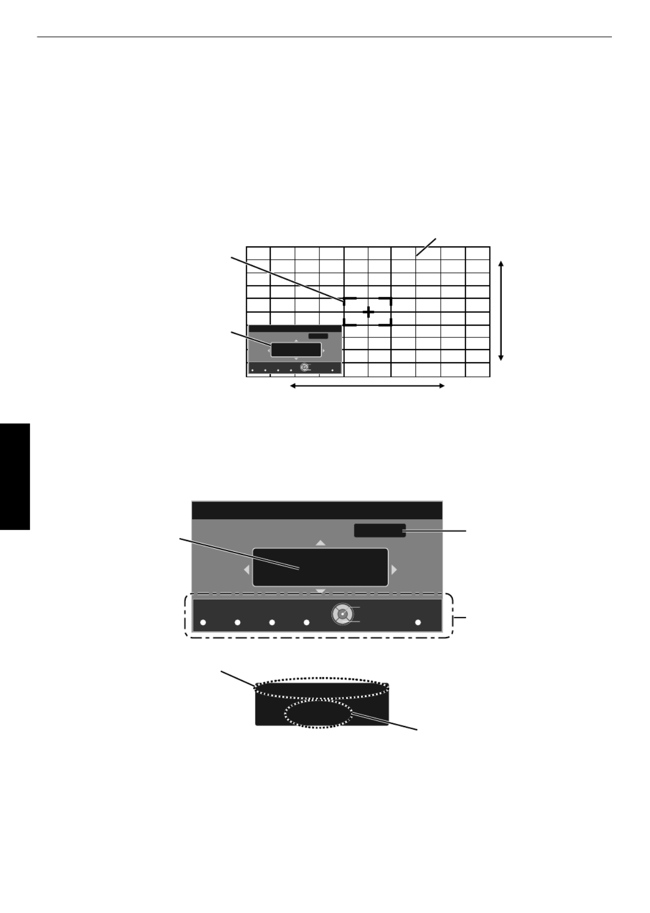
ZoneAdjust Operation Procedure
For fine tuning part using misalignments on aof after overall misalignmentthe screen adjusting the screen
“Adjust(Pixel)” and “Adjust(Fine)”.
The vertically and horizontally partial made. screen can be divided into10 sections for adjustments to be
ASet “Adjust Area” to“Zone”
BSelect and Pattern “Adjust Color” “Adjust Color”
CSelect and Adjust(Fine), press buttonthe [OK]
The selected and adjustment pattern Zone Adjustment window are displayed.
The adjustable on pixels adjusted on range may smallerbe depending the being theentire screen.
Color A.
GAMMA
BACK
ADJUST.
COLOR.
Color P.
COLOR.
A. Area
PIC.
TEMP P. FILE. ADJ.
Red
Pixel Adjust
H 0
0 / 0
V 0
Position
Zone Adjust
V (Vertical)
H (Horizontal)
Zone Adjustment Window
Zone Cursor
Adjustment Pattern
Back
Operate
Select
DPress keys movethe [ ]JKH Ito the thecursor to point to be adjusted
EPressthe [OK] the button to enter Adjustment mode
FUsethe[JKHI]keystomoveandadjustthepixelsintheverticalandhorizontaldirectionsacrosstheentirescreen.
The adjustment setting appears atthe center of the Zone Adjustment window.
H−31
V 7
Color A.
GAMMA BACK
ADJUST.
COLOR.
Color P.
COLOR.
A. Area
PIC.
TEMP P. FILE. ADJ.
Red
Pixel Adjust
H 0
0 / 0
8 / 5
V 0
Position
Position
Zone Adjust
Adjustment Setting
Cursor Position
Remote Control Operation
Guide
Color for
Adjustment
Pixel Adjustment Setting
Back
Operate
Select
GAfter adjustment Adjustment mode iscomplete,pressthe[BACK]buttontoexitthe
58
Adjust/Set

DisplaySetup
Back Color
For the the no setting color of background to there “Blue” or when “Black” is inputsignal.
MenuPosition
For the the setting display position of menu.
MenuDisplay
Setting Description
15sec The display operated menu disappears if it is not for 15 seconds.
On Displays times.the menu at all
LineDisplay
Setting Description
5sec Shows terminal whentheinput for 5 seconds inputisswitched.
Off Not displayed.
SourceDisplay
Setting Description
On Displays signal whenthe inputisswitched.
Off Not displayed.
Logo
Setting Description
On Displays logothe “D ILA” for 5 seconds startup.during
Off Not displayed.
Language
For the setting display language “Italiano”, to “ ”,日本語 “English”, “Deutsch”, “Español”, “Français”, “Português”,
“Nederlands”, “Norsk”, “ ”, “ ”, “ ”.“Svenska”, Русский 中文 or繁體中文
59
Adjust/Set

Function
Trigger
Forconfiguring output to function.12 V anexternal screen equipped with a trigger
Setting Description
Off Nooutput.
On V) the the(Power) Outputs control signals (12 from trigger terminal when poweristurned
on.
After stops Standbythepoweristurnedoff,output whentheunitshiftstothe
mode coolingafter iscomplete.
You can alsooutputsignalsinthe Standby modebypressingthe[OK]button.
On(Anamo) Outputscontrolsignalswhenthe“Anamorphic”settingisswitchedfrom“Off”to“A”
or“B”.
OffTimer
For the the setting timing topower off unit automatically when (“1 Hour”, Hours”, Hours”) “2 “3 Hours”, or “4 it is not
operated of time. for a period
HighAltitude Mode
Set low 900 level).to “On” when location of using the projector at a atmospheric pressure (higher than m above sea
ECOMode
Setting Description
On Minimizes power mode. consumption inthe Standby
Ifthereisnosignaltransmissionoroperation for 30minuteswhileanimageis
projected, turnedthepower is off automatically.
Off Setto“Off”ifRS232C/LANcommunicationisperformedortheHDMIlinkfunction
is inused the Standby mode.
Communication Terminal
For the setting external terminal used orcontrol to be to “RS 232C” “LAN”.
Network
Setting Description
DHCP Client On Obtains automatically DHCP server the IP address fromthe inside theconnected
network.
Off For network settingsconfiguringthe manually.
IP the IP Address For configuring address.
Subnet Mask For subnet configuringthe mask.
Default Gateway For gateway. configuringthe default
MAC MAC of Address Displays the address theunit.
Set Appliesthe network settings.
60
Adjust/Set
Termékspecifikációk
| Márka: | JVC |
| Kategória: | Beamer |
| Modell: | DLA-RS48 |
Szüksége van segítségre?
Ha segítségre van szüksége JVC DLA-RS48, tegyen fel kérdést alább, és más felhasználók válaszolnak Önnek
Útmutatók Beamer JVC

1 Január 2025
15 December 2024
24 Szeptember 2024
22 Augusztus 2024
20 Augusztus 2024
12 Augusztus 2024
6 Augusztus 2024
1 Augusztus 2024
1 Augusztus 2024
1 Augusztus 2024
Útmutatók Beamer
- Beamer Samsung
- Beamer Sony
- Beamer Acer
- Beamer LG
- Beamer Marantz
- Beamer Philips
- Beamer Panasonic
- Beamer Canon
- Beamer Sharp
- Beamer Lenovo
- Beamer Casio
- Beamer Toshiba
- Beamer HP
- Beamer Hisense
- Beamer BenQ
- Beamer Medion
- Beamer Xiaomi
- Beamer Dell
- Beamer Klarstein
- Beamer Prixton
- Beamer Polaroid
- Beamer Technaxx
- Beamer Ricoh
- Beamer Eurolite
- Beamer Epson
- Beamer Asus
- Beamer Hama
- Beamer Renkforce
- Beamer Mitsubishi
- Beamer GPX
- Beamer Hitachi
- Beamer Kodak
- Beamer Optoma
- Beamer Smart
- Beamer Dahua Technology
- Beamer Viewsonic
- Beamer Livoo
- Beamer Smart Tech
- Beamer XGIMI
- Beamer OK
- Beamer Auna
- Beamer Nebula
- Beamer ZTE
- Beamer Showtec
- Beamer Futurelight
- Beamer Overmax
- Beamer Kogan
- Beamer D-Link
- Beamer ION
- Beamer Blaupunkt
- Beamer 3M
- Beamer Pyle
- Beamer Sanyo
- Beamer Salora
- Beamer Lenco
- Beamer Maxell
- Beamer Leica
- Beamer Barco
- Beamer NEC
- Beamer Cameo
- Beamer Krüger&Matz
- Beamer RCA
- Beamer OKI
- Beamer Adj
- Beamer Anker
- Beamer Microtek
- Beamer Celexon
- Beamer Vivitek
- Beamer EasyMaxx
- Beamer Elmo
- Beamer Planar
- Beamer Smartwares
- Beamer Speaka
- Beamer Vogel's
- Beamer Acco
- Beamer Aiptek
- Beamer ASK Proxima
- Beamer Reflecta
- Beamer Yaber
- Beamer Da-Lite
- Beamer Steren
- Beamer Eiki
- Beamer Derksen
- Beamer InFocus
- Beamer Bauer
- Beamer Naxa
- Beamer Emtec
- Beamer Celly
- Beamer Promethean
- Beamer Odys
- Beamer Stairville
- Beamer Laserworld
- Beamer Ibm
- Beamer La Vague
- Beamer Tzumi
- Beamer EKO
- Beamer MicroVision
- Beamer Elite Screens
- Beamer Fun Generation
- Beamer Christie
- Beamer PLUS
- Beamer Varytec
- Beamer AOpen
- Beamer Ultimea
- Beamer Dracast
- Beamer Dukane
- Beamer Dream Vision
- Beamer Knoll
- Beamer DTS
- Beamer Touchjet
- Beamer Boxlight
- Beamer AAXA Technologies
- Beamer Miroir
- Beamer Vankyo
- Beamer Mimio
- Beamer AWOL Vision
- Beamer Atlantis Land
- Beamer KickAss
- Beamer VAVA
- Beamer Beghelli
- Beamer Panamorph
- Beamer Mirabella Genio
Legújabb útmutatók Beamer

2 Április 2025

15 Január 2025

14 Január 2025

13 Január 2025

12 Január 2025

12 Január 2025
12 Január 2025

11 Január 2025
11 Január 2025
11 Január 2025