Használati útmutató Ikegami HLM-3250W
Olvassa el alább 📖 a magyar nyelvű használati útmutatót Ikegami HLM-3250W (64 oldal) a Monitor kategóriában. Ezt az útmutatót 9 ember találta hasznosnak és 2 felhasználó értékelte átlagosan 4.5 csillagra
Oldal 1/64

MODEL
HLM-3250W
FULL HD MULTI FORMAT
LCD COLOR MONITOR
OPERATION MANUAL


SA 1966
SA 1965
CAUTION
RISK OF ELECTRIC SHOCK
DO NOT OPEN
CAUTION: TO REDUCE THE RISK OF ELECTRIC
SHOCK, DO NOT REMOVE COVER
(OR BACK).
NO USER-SERVICEABLE PARTS
INSIDE. REFER SERVICING TO
QUALIFIED SERVICE
PERSONNEL.
The lightning flash with arrowhead inside a triangle is intended to warn the user that
parts inside the product are dangerous and many cause electric hazards.
The exclamation mark inside a triangle is intended to inform users that important
operating and servicing instructions are provided with the equipment.
SA 1966
SA 1965
WARNING: FOR CONTINUED SAFETY, REPLACE SAFETY CRITICAL COMPONENTS
ONLY WITH MANUFACTURE’S RECOMMENDED PARTS (REFER TO SERVICE
LITERATURE).
NOTE:
This equipment has been tested and found to comply with the limits for a Class A digital device,
pursuant to Part 15 of the FCC Rules. These limits are designed to provide reasonable protection
against harmful interference when the equipment is operated in a commercial environment. This
equipment generates, uses and can radiate radio frequency energy and, if not installed and used in
accordance with the instruction manual, may cause harmful interference to radio communications.
Operation of this equipment in a residential area is likely to cause harmful interference in which case
the user will be required to correct the interference at his own expense.
CAUTION;
ANY CHANGES OR MODIFICATIONS NOT EXPRESSLY APPROVED BY THE PART RESPONSIBLE
FOR COMPLIANCE COULD VOID THE USERS AUTHORITY TO OPERATE THE EQUIPMENT.
WARNING: TO REDUCE THE RISK OF ELECTRIC SHOCK, DO NOT EXPOSE THIS
EQUIPMENT TO RAIN OR WATER.
Instructions for Disposal of Electric and Electronic Equipment in Private Household
Disposal of used Electric and Electronic Equipment
(Applicable in the European Union and other European countries with separate collection systems)
This symbol on the product, or in the related documents in the package, indicates that this product
shall not be treated as normal household waste. Instead, it should be taken to a proper applicable
collection point or depot for the recycling of electric and electronic equipment.
By ensuring this product is disposed of correctly, you will help prevent possible negative consequences for the
environment and human health, which could otherwise be caused by inappropriate waste handling of this
product. The recycling of materials will help to conserve natural resources.
For more detailed information about recycling of this product, please contact your local city authority, your
household waste disposal service or the place where you purchased the product.
DECLARATION of CONFORMITY:
The “CE” mark means the products as mentioned below will meet the intent of the following Directives and Standards.
Inrush current according to EN55103-1 Annex B is as follows.
HLM-3250W: 17.4 A
Directives : 93/68/EEC, 2004/108/EC, 92/31/EEC for EMC (electromagnetic compatibility)
2006/95/EC for Low voltage (Safety)
Standards : HLM-3250W : EN55103-1-E4, EN55103-2-E4, EN60950-1

IMPORTANT SAFETY INSTRUCTIONS
1.General
1) Read all instructions provided.
2) Save these instructions for future use.
3) Follow all warnings and instructions marked
on the television equipment.
4) Never insert objects of any kind into this
television monitor through cabinet slots as
they may come in contact with dangerous
voltage points or short out parts, resulting in
fire or electric hazards, Never spill liquid of
any kind on the television monitor.
5) Do not attempt to service this television
monitor yourself as operating or removing
covers many expose you to dangerous voltage
or other hazards, Refer all servicing to
qualified service personnel.
6) Do not use attachments not recommended by
the television equipment manufacturer as they
may result in the risk of fire, electric shock, or
injury to persons.
7) This television monitor has been preadjusted
to meet the respective broadcasting standard
signals. So, it cannot be used with the signals
of different broadcasting standards.
8) When keeping or transporting the unit for a
long time, pack it in the supplied carton or
equivalent.
2.Power supply
1) This television equipment should be operated
only from the type of power source indicated on
the marking label.
2) This television equipment is provided with a
three-wire grounding type plug with a third
(grounding) pin. This plug will only fit into a
grounding-type power outlet. This is a safety
feature. If you are unable to insert the plug
into the outlet, contact your electrician to
replace your obsolete outlet.
Do not defeat the safety purpose of the
grounding-type plug.
3) When connecting and disconnecting the
power cable, be sure to hold the plug.
4) Do not allow anything to rest on the power
cord. Do not place this television equipment
where the cord will be abused by persons
walking on it.
5) For added protection for this television
equipment during a lightning storm, or when
it is left unattended and unused for long
periods of time, unplug it from the wall outlet.
This will prevent damage to the equipment
due to lightning and power-line surges.
6) Do not overload wall outlets and extension
cords as this can result in fire or electric shock.
3.Usage and location
1) Do not use this television equipment near
water - for example, near a bath tub,
kitchen sink, or laundry tub, in a wet basement,
or near a swimming pool, or the like.
2) Do not place this television equipment on an
unstable cart, stand, or table. The television
equipment may fall, causing serious injury to
children and adults, and serious damage to the
equipment. Use only with a cart or stand
recommended by the manufacture, or sold
with the television equipment. Wall or shelf
mounting should follow the manufacture’s
instructions, and should use a mounting kit
approved by the manufacture.
Television equipment and cart combination
should be moved with care. Quick stops,
excessive force, and uneven
surfaces may cause the
equipment and cart
combination to overturn.

3) Slots and openings in the cabinet and the back
or bottom are provided for vitiation, and to
ensure reliable operation of the monitor and
to protect it from overheating, these openings
should never be blocked or covered. The openings
should never be blocked by placing the
television equipment on a bed, sofa, rug, or
other similar surface. (This television
equipment should never be placed near or
over a radiator or heat register.)
This television equipment monitor should not
be placed in a built-in installation such as a
bookcase unless proper ventilation is
provided.
4) Avoid operating or placing (keeping) in a hot
(+40ºC or over) or cold (less than 0ºC), high
vibration, or dusty place. Avoid operating or storing
in a place exposed to direct sunlight.
5) If an image of extremely high brightness is
displayed on the screen for a long time, the
panel may get burned in.
4.Cleaning
1) Unplug this television equipment from the
wall outlet before cleaning. Do not use liquid
cleaners or aerosol cleaners. Use a damp cloth
for cleaning.
2) Do not use thinner or benzine for cleaning.
Otherwise, the cabinet may deform or the
paint may peel away.
IMPORTANT SAFETY INSTRUCTIONS
5 r.Repai
1) Unplug this television monitor from the wall
outlet and refer servicing to qualified service
personnel under the following conditions:
a. When the power cord or plug is damaged
or frayed.
b. If liquid has been spilled into the
television.
c. If the television monitor has been exposed
to rain or water.
d. If the television does not operate normally
by following the operating instructions.
Adjust only those controls that are
covered by the operating instructions as
improper adjustment of other controls may
result in damage and will often require
extensive work by a qualified technician
to restore the television monitor to normal
operation.
e. If the television monitor has been dropped
or the cabinet has been damaged.
f. When the monitor exhibits a distinct
change in performance - this indicates a
need for service.
2) When replacement parts are required, be sure
the service technician has used replacement
parts specified by the manufacture that have
the same characteristics as the original part.
Unauthorized substitutions may result in fire,
electric shock, or injury to persons.
3) Upon completion of any service or repairs to
this monitor, ask the service technician to
perform routine safety checks to determine
that the television is in safe operating
condition.
4) For repair service, contact Ikegami’s
authorized sales representative or Ikegami
service desk directly.

PRECAUTIONS FOR OPERATIONS
1) Never let this unit fall or subject it to strong
shock.
2) Do not remove the cabinet unless necessary.
High-voltage parts are contained in the
cabinet and they are very dangerous if you
touch then. Only qualified service engineers
are allowed to adjust the internal parts of the
cabinet.
3) This color monitor has been adjusted to
signals conforming to each broadcasting
standard.
It cannot be used for signals of different
broadcasting standards.
Be sure to operate the color monitor within
the voltage range marked on its back.
4) If cabinet or screen is dirty, wipe with soft
cloth. At this time, avoid using benzine or
thinner, otherwise the paint may peel away.
5) Note that, if video signals with high
luminance are monitored on the LCD panel over a
long period of time, the panel may burn in the
image.
6) The socket-outlet shall be installed near the
equipment and shall be easily accessible.
7) Avoid using or storing this unit in the
following places:
• Hot (+40ºC or more) or cold (0ºC or less)
places, especially where this unit may be exposed
to the direct rays of the sun.
• Humid and dusty places.
• Places where there is considerable
vibration.
• Places exposed to rain or water.
• When storing or transporting this unit, pack it
in the supplied carton or equivalent.
8) If no image can be monitored even after
performing user adjustment or the unit
appears faulty, do not dismantle this unit by
yourself. In such cases, contact the Ikegami
service desk.
9) Should this unit fail within one year after
delivery, it will be repaired free of charge
unless the malfunction was caused by
mishandling or misuse of the user.
However, the fuses are not covered
by the warranty.
10) The specifications and appearance of this unit
may be subject to change for further
improvement without prior notice.

In order to use the monitor safely, read through this manual and pay attention to the following points
in particular.
1 f.Do not use any power supply other than the speci ied one (AC).
2.Do not give a shock to the monitor.
Be very careful to keep the monitor from shocks because glass is used inside the LCD.
3.Do not use or store the monitor in the following places.
Place where the amb s out of specient temperature i
When installing the monitor on a monitor shelf, switcher table, rack, etc., make sure in advance
that the temperature of the installation location is within the specified range.
In the case of an outdoor setup, even if the ambient temperature is within the specified range, the
inside of the monitor may be heated by direct sunlight. Therefore, keep radiation in mind. (Avoid
direct sunlight.)
Never block the air outlet at the rear of the monitor and the air inlet at the side. Make sure in
particular that a blackout curtain or the like does not block the air outlet.
Place exposed to ra n, snow or h gh hum d tyi i i i
Use of the monitor in such a place will cause electric leakage or failure.
4 ght. Avoid exposing the LCD screen to direct sunli .
Exposure of the LCD screen to direct sunlight for a long time will degrade the film. Therefore be
careful of direct sunlight when using the monitor outdoors.
5.Cautions in handling the front protective panel
Be careful not to touch the LCD panel front surface with bare hands, unless necessary. When
wiping the dust off the surface, use soft, dry cloth and take care not to rub the surface strongly. Do
not use thinner or benzine.
6.Do not touch liquid crystal leaked from the monitor's display surface.
If the monitor's display surface is accidentally broken and the liquid crystal leaks, be careful
never to put the liquid in your mouth, inhale it and allow it on your skin. If the liquid gets into
your eye or mouth, immediately rinse it with water and get medical attention.
If the liquid contacts your skin or clothes, immediately wipe it off using alcohol or the like and
wash the stained spot with soap and water. Do not leave the liquid intact, because otherwise your
skin or clothes may be affected.
7.Do not display the same pattern for a long time.
Note that residual image may be generated if the same pattern is displayed for a long time.
• Turn off the power when the monitor is not used.
To avoid residual images, preferably take the following measures.
• Change the screen regularly.
• Display the whole screen in white.
8.Avoid operation at low temperatures.
Note that the backlight function will be degraded at low temperatures, leading to shorter service
life. It is recommended to use the monitor at normal temperatures.
Precautions Upon Use

* VGA, SVGA and XGA are registered trademarks of International Business Machines Corporation.
* Specifications and external dimensions are subject to change without prior notice.
9. Avoid operation or storage in a place exposed to corrosive gas.
Operation or storage in a place where any corrosive gas such as sulfur dioxide, hydrogen sulfide,
chlorine or ammonia is generated may lead to a significant reduction in the monitor service life. It
may also cause failure or electric leakage.
Also avoid using the monitor in a location exposed to high salty wind.
10. Do not use this monitor for such applications as space appliance, nuclear control system as
any medical equipment involving human life.
Quality of LCD panel
Note that because the LCD panel mounted on the monitor is manufactured through the use of
high-precision technology, 99.99% or more of the pixels are effective, but 0.01% or less of them
may be lacking in brightness or lit up constantly.
Internal fan
The internal fan does not run constantly but automatically starts running when the internal
temperature of the monitor rises. When the environmental temperature is low, the internal fan
may not be running, which indicates no fault condition.
At power-on, the fan rotates for a moment for checking its own performance.
In the case of outdoor use, even if the ambient temperature is low, the fan may start running when
the internal temperature of the monitor rises.
Suppose that the fan does not operate properly at power-on or at high temperatures. In such case,
the message "FAN ERROR!" will appear at the top of the screen.
The brightness of the backlight may be reduced in order to keep the internal temperature of the
motor from rising.
If the message "FAN ERROR!" is displayed, contact your dealer or Ikegami service desk.
Warranty
If the product should fail within one year from the date of delivery in spite of the proper use, the
manufacturer will repair the product free of charge. Even if the product is covered by the warranty,
however, the customer will be charged for labor and parts in the following cases.
1. Failure and damage caused by the following:
• Improper use
• Repair or modification performed by the customer
• Transportation, transfer, falling, etc. after the purchase of the product
• External factors such as natural disasters and over-voltage
2. Aged deterioration of the liquid crystal panel and backlight (change in brightness, increase in
the number of luminescent spots and dark points, etc.)
3. Damage, discoloration and degradation of the cabinet including the LCD front protective panel
4. Replacement of the accessories and fuse
If no image comes out in spite of routine adjustment or if the product should seem to fail,
contact your dealer or Ikegami service desk.
Accessories
The monitor comes with the following accessories. Be sure that they are included.
1. Fixed stand (attached on the monitor)
2. Operation manual: 1 copy
3. Parallel remote connector: 1 set
4. Power cable: 1 pc.

CONTENTS
IMPORTANT SAFETY INSTRUCTIONS
PRECAUTIONS FOR OPERATIONS
Cautions for Rack-Mount.
Precaut ons Upon Usei
For the f me use after purchaseirst-ti
1 Outl ne. i .......................................................... 1
1-1. Outline ................................................. 1
1-2. Features ............................................... 1
2 ons.Names of parts and their Functi .......... 3
2-1. Front Controller Parts ..................... 3
2-2. Rear panel (left bottom) .................. 5
2-3. Rear panel
(
video inputs/outputs
) .
6
2-4. Option (CM-240 input/output) ........ 7
2-5. Option (EA-240A output) ................. 7
2-6. Option (EA-240D output) ................. 8
3 Markers. ......................................................... 9
3-1. Types of Markers ............................... 9
4 ons.MENU Functi .......................................... 10
4-1. List of MENU ...................................... 10
4-2. Flow of MENU Operations ............. 12
4-3.
Description of MENU 1 Functions ...
15
4-4.
Description of MENU 2 Functions ...
16
4-5.
Description of MENU 3 Functions ...
18
4-6.
Description of MENU 4 Functions ...
19
4-7.
Description of MENU 5 Functions ...
20
4-8.
Description of MENU 6 Functions ...
21
4-9.
Description of MENU 7 Functions ...
22
4-10.
Description of MENU 8 Functions ...
23
4-11.
Description of MENU 8
(USER MARKER) Functions and
Making Settings ....................................
25
4-12.
Description of MENU 9 Functions ...
29
4-13.
Description of MENU 10 Functions ...
30
4-14.
Description of MENU 11 Functions ...
31
4-15.
Description of MENU 12 Functions ...
32
4-16.
Description of MENU 13 Functions ...
32
5 on .Preset Menu Functi ................................. 37
5-1. List of preset menu ........................... 37
5-2. Description of preset menu ............ 37
5-2- ①Selection of files ........................... 37
5-2- ②Change of preset data ................. 38
5-2- ③Display of preset data list .......... 39
5-2- ④Copying of file data ..................... 39
5-2- ⑤Setting of file change operation
at the time of channel change ... 39
5-2- ⑥Setting of data protection
password ........................................ 39
6 on.Mouse menu functi ................................. 41
6-1.
Basic procedure of the mouse menu ....
41
6-2.
Basic procedures on the MENU and
PRESET MENU screens ..........................
42
7 f cat ons. Speci i i ............................................. 43
7-1. General specifications ..................... 43
7-2. Rated performance ........................... 43
7-3. Specifications for liquid crystal
display (LCD) module ...................... 45
7-4. Functions ............................................ 46
7-5. Remote control .................................. 46
8. Applicable Standards ................................. 47
8-1. Safety standards ................................ 47
8-2. Electromagnetic interference ........ 47
8-3. Environmental regulations ............. 47
9. Mounting Bracket ....................................... 47
10 Opt ons. i ........................................................ 47
11. i .............................................. External V ew 48
Data 1 PC Input S gnal Compat ble Formati i .. 49
Data 2 Embedded analog aud o outputsi
(EA-240A) ............................................. 49
Data 3 Parallel Remote P n Funct oni i ............. 50
Data 4 Control w th Remote Controlleri ......... 52

- 1 -
H
H
H
H
HLM-3250W FULL HD Mult
LM-3250W FULL HD Mult
LM-3250W FULL HD Mult
LM-3250W FULL HD MultLM-3250W FULL HD Mult -Format LCD Color Mon
-Format LCD Color Mon
-Format LCD Color Mon
-Format LCD Color Mon-Format LCD Color Mon tor
tor
tor
tortor
i
i
i
iii
i
i
ii
HLM-3250W FULL HD Mult -Format LCD Color Mon tori i
1.Outline
1-1 Outl ne. i
This 32-inch type HDTV/SDTV multi-format color
monitor employs a full high-definition liquid crystal
panel for reduction in thickness, weight and power
consumption, and is designed for use in various spaces
such as sub-control rooms, editing rooms, monitor wall,
transmission control desks, and outside broadcast vans.
This monitor is compatible with the functions and
operation of the HTM/TM series CRT monitors, so that
it can realize the functions necessary for a broadcasting
service monitor with conventional operation.
1-2 Features.
(1) H gh performance l qu d crystal paneli i i
The Full-HD (1920 x 1080 dots) 10-bit liquid crystal
panel features high brightness, high contrast, wide
viewing angle, quick response and good color
reproducibility. Accordingly, realistic images can be
displayed with higher-fidelity gradation but without
having to resize the input pixels. This unit is best suited
for shelf-mounted monitoring applications.
(2) Multi-format
The monitor supports various broadcasting formats.
The monitor automatically identifies various types
of input signal formats. (optional component input: set
on MENU)
•480i/59.94 (NTSC) •1035i/60, 59.94
•575i/50 (PAL-B) •1080i/60, 59.94
•480p/59.94 (*1) •1080i/50
•1080psF/30 •720p/60, 59.94
•1080psF/25 •720p/50
•1080psF/24, 23.98 •720p/30, 29.97
•1080p/60, 59.94 •720p/24, 23.98 (*2)
•1080p/50 •720p/25
•1080p/30, 29.97
•1080p/25
•1080p/24, 23.98
(*1) RGB/YPbPr input only
(*2) SDI input only
(3) Di iverse nput sources
The monitor is standard equipped with two SDI
signal (compatible with both HD/SD 4:2:2) inputs and
two analog composite signal inputs. It also comes
standard with one DVI-D signal input (VGA/SVGA/
XGA/WXGA/SXGA/UXGA/WUXGA).
The multi-SDI input (*) compatible with 3G-SDI
(single), analog PC input and RGB/YPbPr inputs are
optionally available.
* Under development (scheduled to be released in
spring 2009, version upgrade of the monitor itself
needed)
(4) Compati i ib l ty with embedded audio
Standard equipped with an embedded audio feature,
the embedded audio signals multiplexed with HD-SDI
signal or SD-SDI (4:2:2) signal can be automatically
recognized and the audio output can be heard through
the built-in stereo speakers or stereo headphones. The
monitor also has a standard embedded audio level
meter display on the screen.
Using an optional device, the embedded audio signal
may be handled as an analog output (when the EA-
240A is mounted) or as an AES/EBU output (when the
EA-240D is mounted).
Besides, the optional 3G-SDI (single) multi-SDI
module comes in two types: Embedded analog audio
output type (D3G-240A*) and AES/EBU output type
(D3G-240D*).
* Under development (scheduled to be released in
spring 2009)
(5) Remote control functions
The monitor can be remote-controlled with the use
of four remote control functions. Depending on the place
of installation and type of operation, the parallel, serial
or wireless mode can be used.
In addition to the conventional parallel remote
control (pin assignment by user is possible), the monitor
also comes standard with a serial remote input
interface that enables remote control with just one BNC
coaxial cable.
Up to 99 monitors can be remote-controlled
individually or concurrently using an optional serial
remote controller SRC-301A/Z simply with Ikagami’s
various monitors being loop-through connected.
An infrared wireless remote controller RCT-30A is
also optionally available.
The RS-485 input/output terminals are also standard
designed for control of up to 32 units.

- 2 -
(6) Built-in markers
4:3 (16:9 mode), 13:9, 14:9, 15:9, 16:9 (4:3 mode),
1.85:1 (16:9 mode) and 2.35:1 (16:9 mode) line markers
can be displayed.
The monitor can also get the 1%-stepwise safety
marker displayed in the range of 80-99% with respect
to the line marker area.
The safety markers over the effective screen can be
equally preset 1% by 1% in the range of 80-99%.
The monitor also comes standard abundantly with
five-part split and ten-part split crosshatch markers
useful for location alignment.
(7) User marker display function
Up to 10 different user markers, such as line and
box markers, are presettable pixel by pixel to your
desired positions and sizes. The line and box drawing
settings can be easily made with not just the switch
but also the USB mouse. Resulting complicated data
may also be saved on a USB memory so that the data
can be copied to another monitor or stored in a PC.
This function is optimum for positioning in editing
the layout and its display for various types of
information such as teleshopping.
* Patent pending
(8) Shadow function
The shadow function is to shade the area other than
a 4:3 (16:9 mode), 13:9, 14:9, 15:9 or 16:9 (4:3 mode)
marker area on images. The shadow contrast can be
set at 0%, 20%, 40% or 60% on the MENU. The use of
this function allows you to instantly visualize the image
area when converting images with an aspect ratio of
16:9 to those with an aspect ratio of 4:3 or vice versa.
This shadow function can be turned on/off by remote
control and prompt switching is therefore realized.
(9) Various built-in test signals
The monitor is standard equipped with color bar
signal, grayscale signal with pluge pattern, and window
signal. Various adjustments can therefore be made on
the monitor alone.
(10) Time code display function
It is possible to display the time code (VITC)
multiplexed into HD-SDI signal (ARIB STD-B4 Ver2.0)
on the screen.
The display comes in two sizes, large and small, and
its brightness in three levels.
(11) Waveform monitor/Vector scope display
functions
Waveform monitor of brightness signal can be
displayed. The display comes in two sizes, NORMAL
and SMALL, and its brightness in three levels. The
waveform can also be displayed in any of three
selectable positions and in one of two colors: GREEN
and WHITE. The vector scope can also be readily
displayed.
(12) 2-picture split display function
A previously captured still image and a currently
incoming moving image are displayed split onscreen.
Just one monitor serves to compare the pictures from
two cameras at once on its screen.
(13) Dot-by-dot display function
All the picture elements of an input signal are
displayed 1:1 according to the pixels of the LCD panel
without scaling the incoming signal (enlarging or
reducing the input signal according to the LCD pixels).
This function is useful in checking transmitted input
signals for pixel defects, camera CCD’s scratches, etc.
Only the 1080i/p signal is displayed in 1:1 in the
normal scanning status.
(14) External memory function
Various data (MENU settings, PRESET data, etc.)
can be saved on a USB memory and copied to a PC, on
which the data is ready to manage. Such data may also
be copied to another monitor.
* Keep in mind that when copying the PRESET data
to another monitor, they may be different from monitor
to monitor.

- 3 -
⑦INPUT SELECT switch
Use the
▲
and
▼
switches to change input
sources.
※“OPT” is enabled when an optional module input
is selected.
⑧ CH-B switch
Use this switch to change channels in the SDI or
VBS input mode.
⑨ TEST switch
Press this switch to display internal test signals.
The switching between the following three types
of signals is done each time this switch is pressed.
2.Names of parts and their Functions
2-1.Front Controller Parts
①POWER switch
Turns on/off the power to the monitor.
※This switch is not for turning on/off the AC power
supply to the monitor.
※Several seconds are required for images to appear
after power-on.
② MENU switch
Press this switch to display a menu screen or
change the menu screen.
※This switch is disabled when the preset menu is
displayed.
③ PRESET switch
Press this switch to display the preset menu.
※This switch is disabled when the menu is displayed.
④ENT switch
Press this switch to execute menu operations.
⑤ESC switch
Press this switch to exit from a menu.
⑥
▲
(UP)/
▼
(DOWN)/ (LEFT)/ (RIGHT) switch
Use this switch to change menu items or the setting
of each item when a menu or preset menu is
displayed.
With the menu off and the marker on, the image
pattern can be preset with the and switches
and the safety marker area with the
▲
and
▼
switches in the range of 80-99%.
0%
+2%
-2%
<Normal Screen> <100% W ndow>i
<Sta rcase wave w th pluge> <Color Bar>i i
0~100% sta rcase wavei
PRE.
MANUAL
CHROMA BRIGHT CONT AUDIO
F1
F2
MONO ASPECT SCAN
APT SCREEN MARK
CHB
TEST
SDI
VBS
DVI
OPT.
PRESETMENU
ESCENT
SDIERROR
PRE.
MANUAL
CHROMA BRIGHT CONT AUDIO
F1
F2
MONO ASPECT SCAN
APT SCREEN MARK
CHB
TEST
SDI
VBS
DVI
OP T.
PRESETMENU
ESCENT
SDIERROR
22 23 4 5 6 9 11 15 16 17 18 19 20 21
262524
26
1 2 3 7 8 10 12 13 14

- 5 -
23
Infrared rece ver of w reless remote controli i
When a wireless remote controller (RCT-20A/RCT-
30A) is used, point it towards this receiver.
24
Stereo headphones output (stereo mini-jack type)
Analog audio signals or embedded audio signals
are fed out of this terminal.
The analog and embedded inputs can be selected
on MENU7.
25
USB terminal
Connect a USB memory, and the monitor’s data
can be saved on the USB memory or the data on
the USB memory can be downloaded on another
monitor.
Connect a USB mouse, and the user markers can
be drawn.
2-2.Rear panel (left bottom)
①
②
③
ACIN
100-120V
200-240V
POWER
①MAIN POWER switch
Turns on/off the AC power supply to the monitor.
To operate the monitor, turn ON this MAIN
POWER switch as well as the POWER switch on
the front panel.
②AC power input
Insert the provided AC cable here to supply AC
power.
③Lock
After inserting the AC plug, lock the AC plug with
this lock to prevent it from disconnecting.
26
Stereo speakers
Analog audio signals or embedded audio signals
are fed out of this terminal.
The analog and embedded inputs can be selected
on MENU.
With the headphones being connected, no sound is
heard from the speakers.

- 6 -
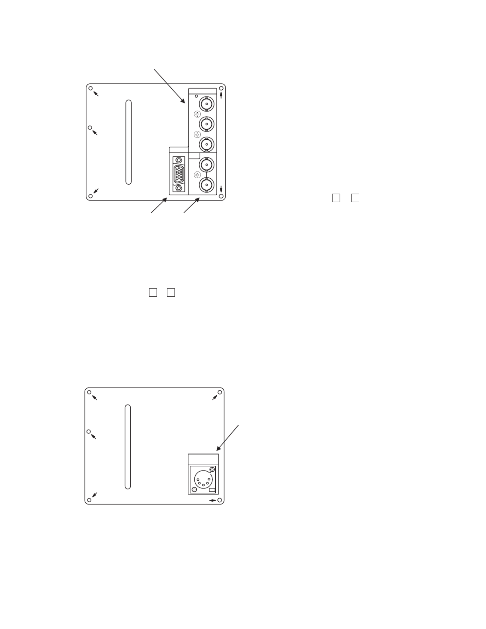
2-3 deo nputs/outputs). Rear panel (vi i
①DVI-D si ignal nput
This connector is used to connect the DVI-D signal
from the PC.
The compatible formats are referred to in "6-2
Rated performance (5)".
②SDI A/B si ignal nput
Input the HD-SDI or SD-SDI (4:2:2) signal here.
The format of input signal is automatically
identified.
③SDI signal output
Output the same selected channel signal from the
A/B channel as channel select is made for
monitoring.
④NTSC/PAL-B analog composite nputi
Input the NTSC/PAL-B analog composite (VBS)
signal here.
Without the loop through connection in place,
connect a terminating plug.
⑤PARALLEL REMOTE s gnal nputi i
Connect the accompanying remote connector here.
For details of pin connections, refer to "Data 3:
Parallel Remote Pin Function" or "4-12.
Description of MENU 9 Functions".
Make sure the cable used is shielded.
②
①
④
⑨
⑧
⑤
⑦
⑥
③
TEST
IN
RS-485
OUT
L
R
AUDIO
CHA
CHB
VBS
MONITOR
OUT
CHB
CHA
HD/4:2:2
SDI
DVI
REMOTE
PARALLEL
SERIAL
⑥SERIAL REMOTE si ignal nput
Connect the BNC cable from the SRC-301A/Z serial
remote controller here.
By adopting the loop through connection, up to 99
monitors can be controlled individually or
collectively.
Without the loop through connection in place,
connect a terminating plug.
Set the monitor ID number on the MENU2 screen.
⑦RS-485 input/output
These are used for remote control with RS-485.
Up to 32 units can be loop-through-connected.
Without loop-through connection, use the optional
terminating device.
※Make sure the cable used is shielded.
⑧Analog audi io nput
Feed analog audio signals here.
⑨TEST terminal for factory adjustment
The TEST terminal is factory adjustment. Connect
nothing to this terminal.
- 7 -
2-4. Option (CM-240 input/output)
①Component (YPbPr/RGB) signal input
Feed component signals.
Set either YPbPr or RGB on MENU1.
When the signal format is 1080i/60 or 1035i/60,
the 1080i/1035 setting must be made on MENU1.
To select this input, set to “OPT.” with the INPUT
SELECT switches (
▲
&
▼
) on the front panel.
Make sure that the “INPUT SELECT” on MENU10
is set at “VIDEO”.
For this purpose, it is also possible to assign the
function keys [F1] and [F2] on the front panel.
①
③ ②
COMPONENT
Y/ G
Pb/B
Pr/R
SYNC
PC
CM-240
②External sync signal input
Feed an external sync signal here when externally
synchronizing component signals.
If not adopting the loop through connection method,
connect the terminating plug.
To switch to EXT SYNC, make the setting on
MENU1.
For this purpose, it is also possible to assign the
function keys [F1] and [F2] on the front panel.
③ Analog PC signal input
Input the PC signal (analog RGB signal) here.
As for the compatible format, refer to the "Data 1:
PC Input Signal Compatible Format".
To select this input, set to “OPT.” with the INPUT
SELECT switches (
▲
&
▼
) on the front panel.
Make sure that the “INPUT SELECT” on MENU10
is set at “PC”.
For this purpose, it is also possible to assign the
function keys [F1] and [F2] on the front panel.
2-5. Option (EA-240A output)
①
EA-240A
AUDIOOUT
(ANALOG)
①Embedded analog audio output
Select one pair of channels out of four paired
channels (eight embedded audio channels
multiplexed in SDI) in the MENU7. The selected
2-channel analog audio signal is outputted from
this connector.
Use XLR-5-11C or equivalent as an output
connector.
For details of pin connection, refer to the "Data 2:
Embedded analog audio outputs (EA-240A)”.
The output is active. When handling the output
unbalanced, use the hot side and ground. (Keep
the cold side open.)

- 8 -
2-6. Option (EA-240D output)
①
EA-240D
AUDIOOUT
(AES/EBU)
CH1-2
CH3-4
CH5-6
CH7-8
①Embedded AES/EBU output
Eight embedded audio channels multiplexed in SDI
are outputted as digital audio signals in AES/EBU
format.
Consumer format (SPDIF) is not supported.
Use a converter when connecting the equipment
of 110 impedance.

- 9 -
3. Markers
3-1. Types of Markers
(1) Safety marker
Active screen area
100% area
(6) Aspect marker + Safety marker
Active screen area
Aspect marker [4:3/13:9/14:9/15:9]
Active screen area
(3) 10-division
crosshatch
Active screen area
(4) Cross marker
Active screen area
(5) Aspect marker
Active screen area
Aspect marker
[4:3/13:9/14:9/15:9]
Safety marker in area,
variable from 80% to 99% (1% increments)
(7) 1.85:1 Aspect marker
Active screen area
1.85:1 Aspect marker
(8) 2.35:1 Aspect marker
Active screen area
2.35:1 Aspect marker
(9) Safety marker
Active screen area (4:3)
Variable from 80% to 99%
(1% increments)
100% area
Active screen area
Active screen area
Active screen area
Active screen area
In the 16:9 aspect ratio display mode (HDTV/SDTV)
Aspect marker
[13:9/14:9/15:9/16:9]
(10) 5-division
crosshatch
(11) 10-division
crosshatch
(12) Cross marker
(13) Aspect marker
In the 4:3 aspect ratio display mode (SDTV)
Variable from 80% to 99%
(1% increments)
(2) 5-division
crosshatch
The displayed markers are set on MENU8.
With no menu onscreen, the image pattern can be changed with the and switches, whereas the safety
marker percentage setting (1% increments) with the
▲
and
▼
switches.

- 10 -
Setting the decoder Y/C separation
Setting the format with YPbPr/RGB 1125 line inputs
Setting the YPbPr/RGB signal format of DVI inputs
Setting the function assignment of F1 (Function 1) switch
Setting SYNC INT/EXT
Setting the automatic/manual aspect ratio change as
per reception channel
Setting the tally lamp display format
Setting the SDI VITC display ON/OFF
Setting the chroma gain-up ON/OFF
Setting the paired channels of embedded audio outputs
Setting the audio input signal out of speakers
Setting the audio level meter display mode
Setting the audio level meter display brightness
Setting the IP conversion mode (FIELD/FRAME)
Adjusting the horizontal screen position
Adjusting the vertical screen position
Setting the audio level meter display channel
Setting the monitor ID code for remote control
Setting the backlight brightness level
Setting the NTSC setup level
Setting the 480i format setup level
Setting the SDI channel lock ON/OFF
Setting the same-size (dot-by-dot) display ON/OFF
Setting the SDI VITC display brightness
Setting the SDI VITC display size
Setting the waveform display ON/OFF
Setting the waveform display brightness
Setting the waveform display size
Setting the waveform display position (right/center/left)
Setting the waveform display color (white/green)
Executing the 2-picture split mode
Setting the 2-picture split mode display area
Setting the function assignment of F2 (Function 2) switch
Setting the format display ON/OFF at signal switching
Setting the YPbPr/RGB 1125 signal format of COMP. inputs
Setting the VIDEO line signal of DVI inputs
Setting the VBS input
Various settings of CM-240 COMPONENT inputs
Setting the VECTOR SCOPE display ON/OFF
Setting the VECTOR SCOPE display brightness
Setting the VECTOR SCOPE display magnification ratio
Setting the VECTOR SCOPE display position
(right/center/left)
Setting the VECTOR SCOPE display color (white/green)
Setting the COLOR BOX scale display (75%/100%)
Setting the audio level meter display ON/OFF
MENU MENU1
(FORMAT)
MENU2
(MODE)
MENU6
(VIDEO)
MENU7
(AUDIO)
9.FORMAT DISPLAY
2.→Y/C SEP.
6.COMP. FORMAT
8.→1035/1080i
4.DVI FORMAT
1.FUNCTION1 MODE
10.SYNC
4.CHANGE ASPECT
6.TALLY
1.SDI VITC
1.CHROMA GAIN UP
2.IP MODE
1.LINE/SP CH.
2.SP INPUT SEL
3.LEVEL INDICATOR
4.→MODE
3.H Cosition
4.V Position
6.→DIMMER
5.→CHANNEL
3.REMOTE NO.
5.BACKLIGHT DIM.
1.VBS FORMAT
3.→NTSC SETUP LVL
9.→480i SETUP LVL
8.SDI CH LOCK
MENU3
(VITC/WFM)
7.REAL SCAN
2.→DIMMER
3.→SIZE
4.WFM DISPLAY
5.→DIMMER
6.→SIZE
7.→POSITION
8.→COLOR
MENU5
(SCREEN CAPTURE)
1.SCR CAPTURE
2.→AREA
2.FUNCTION2 MODE
5.→YPbPr/RGB
7.→YPbPr/RGB
(The dashed-line-boxed items are effective with the CM-240 mounted.)
1.VECTOR SCOPE
MENU4
(VECTOR SCOPE) 2.→DIMMER
3.→MAGNIFICATION
4.→SCALE
5.→POSITION
6.→COLOR
4. MENU Functions
4-1. iL st of MENU
All functions can be executed in the MENU screen.

- 11 -
MENU10
(PC SETUP) 1.DVI SETUP
2.→EXPANSION
7.AUTO ADJUST
11.→PHASE
10.→CLOCK
8.→H POSITION
9.→V POSITION
Setting the PC signal with DVI input
Setting the display size for PC signal with DVI input
Executing the PC input automatic adjustment
Adjusting the analog PC input phase
Adjusting the analog PC input clock
Adjusting the PC input horizontal screen position
Adjusting the PC input vertical screen position
MENU9
(PARALLEL REMOTE)
MENU12
(INFORMATION)
1.PIN FUNCTION
1.MPU VERSION
Setting the parallel remote pin function
Displaying the MPU version
MENU11
(RESET) 1.LOAD FACTORY
2.RESET FILE
Executing the initialization to the factory settings
Selecting the preset files to be initialized
MENU8
(MARKER)
10.CENTER MARKER
8.ASP MARKER MODE
Setting the center cross marker ON/OFF
1.MARKER (16:9)
3.→ASPECT
2.→SAFETY AREA
Setting the 16:9 safety marker area
(80-99% (1% increments))
Setting the type of aspect marker at 16:9 display
2.WORKING TIME
Displaying the operating hours
3.OPTION MODULE
Displaying the optional modules mounted
Setting the type of marker displayed at 16:9 aspect ratio
4.→AREA IN ASPECT
Setting the safety marker (80-99% (1% increments))
in aspect marker area
5.MARKER (4:3)
7.→ASPECT
6.→SAFETY AREA
Setting the type of aspect marker at 4:3 display
Setting the type of marker displayed at 4:3 aspect ratio
Setting the 4:3 safety marker (80-99% (1% increments))
Setting the aspect marker display mode
9.→SHADOW LEVEL
Setting the shadow contrast level with shadow onscreen
11.MARKER LEVEL
Setting the marker display level
12.MARKER COLOR
Setting the marker display color
MENU13
(USB MEMORY)
1.SETTING DATE TIME
Setting the file s date/time to write on USB memory
<USBMEMORY→MONITOR>:
Data write menu from monitor to USB memory
2.→DATE Y/M/D
Setting the file s year/month/day to write on USB memory
3.→TIMEH:M
Setting the file s hour/minute to write on USB memory
4.WRIGHTTOMEM
<USBMEMORY→MONITOR>:
Download menu from USB memory to monitor
Executing to write on USB memory
5.CONTENTS TO
DOWNLOAD
Selecting the data contents to be downloaded from
USB memory to monitor
6.DOWNLOAD
Downloading from USB memory to monitor
13.USER MARKER
Setting the user marker display ON/OFF
Executing the user marker for the drawing setting menu
14.→SETTING
(1/2)
(2/2)
3.COMP SETUP
Setting the CM-240 system
4.→INPUT SELECT
5.→EXPANSION
6.→XGA/WXGA
Setting the analog PC/COMPONENT input selection
Setting the analog PC input display size
Setting the analog PC input with XGA or WXGA input
□MENU&SW
Data in the menu-based and switch-preset status
□USER MARKER
Data of user markers
□PRESET
Various preset data
(The dashed-line-boxed items are effective with the CM-240 mounted.)

- 12 -
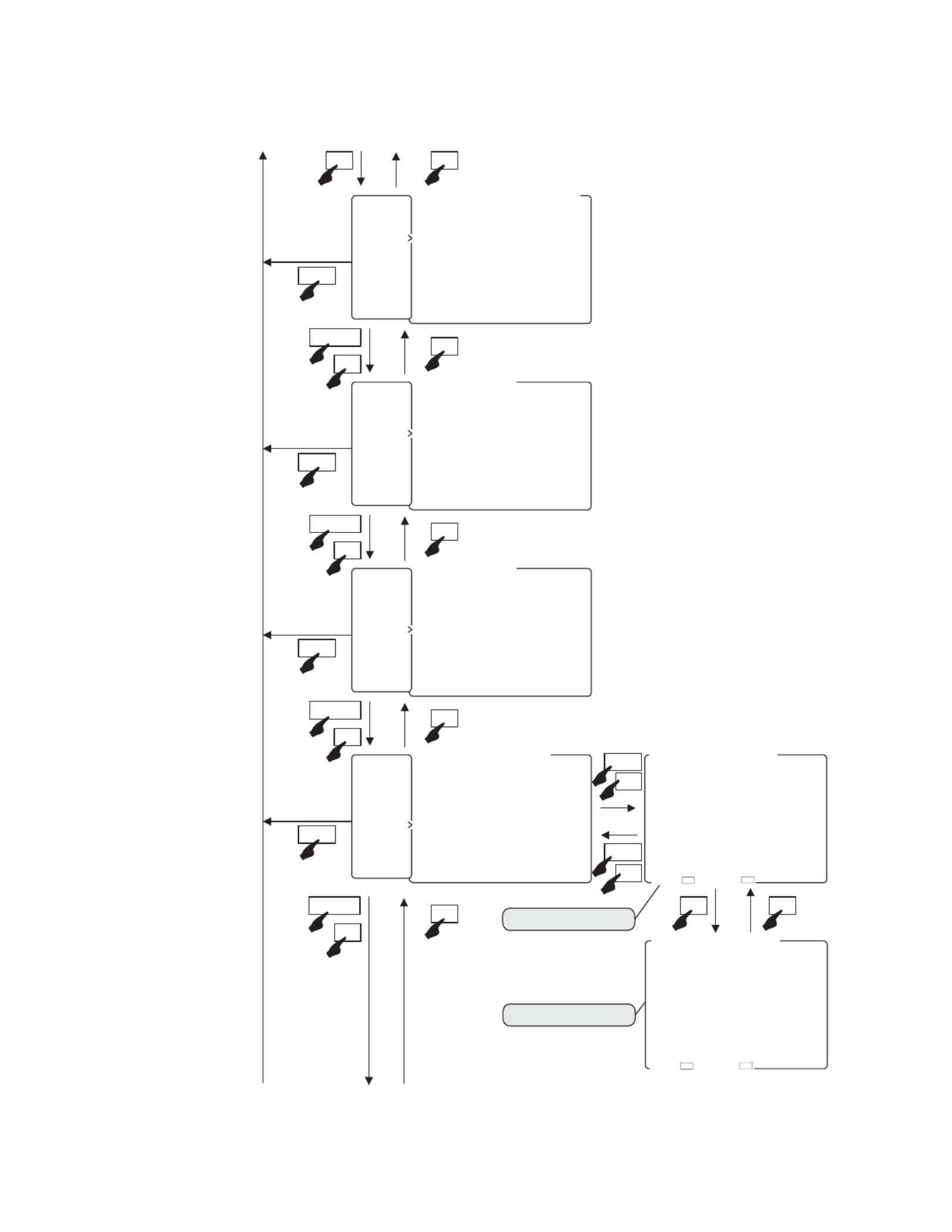
4-2 Flow of MENU Operat ons. i
MENU can be switched as follows using the MENU switch.
Set the format of each input signal.
Set various modes.
Set the SDI VITC- and WFM-related items.
1.VBS FORMAT
2.→Y/C SEP. 2DYCS
3.→NTSC SETUP LVL 0%
4.DVI FORMAT
5.→YPbPr/RGB YPbPr
6.COMP. FORMAT
7.→YPbPr YPbPr
8.→1035/1080i 1080i
9.→480i SETUP LVL 0%
10.SYNC INT
MENU1(FORMAT):1080i
1.FMT
2.MODE
3.TC/WF
4.VSC
5.CAPT.
6.VIDEO
7.AUDIO
8.MARK
9.P.REM
10.PC
11.RESET
12.INFO.
13.USB
1.FUNCTION1 MODE WFM
2.FUNCTION2 MODE VITC
3.REMOTE NO. 01
4.CHANGE ASPECT AUTO
5.BACKLIGHT DIM. 20
6.TALLY R/G
7.REAL SCAN OFF
8.SDI CH LOCK OFF
9.FORMAT DISPLAY ON
MENU2(MODE)
1.FMT
2.MODE
3.TC/WF
4.VSC
5.CAPT.
6.VIDEO
7.AUDIO
8.MARK
9.P.REM
10.PC
11.RESET
12.INFO.
13.USB
1.SDI VITC OFF
2.→DIMMER MID
3.→SIZE NORMAL
4.WFM DISPLAY OFF
5.→DIMMER HIGH
6.→SIZE NORMAL
7.→POSITION RIGHT
8.→COLOR WHITE
MENU3(VITC/WFM)
1.FMT
2.MODE
3.TC/WF
4.VSC
5.CAPT.
6.VIDEO
7.AUDIO
8.MARK
9.P.REM
10.PC
11.RESET
12.INFO.
13.USB
1.VECTOR SCOPE OFF
2.→DIMMER HIGH
3.→MAGNIFICATION ×1
4.→SCALE 100%
5.→POSITION RIGHT
6.→COLOR WHITE
MENU4(VECTOR SCOPE)
1.FMT
2.MODE
3.TC/WF
4.VSC
5.CAPT.
6.VIDEO
7.AUDIO
8.MARK
9.P.REM
10.PC
11.RESET
12.INFO.
13.USB
Set the VECTOR SCOPE-related items.
ESC
ESC
ESC
ESC
Main menu enabled Sub menu enabled
▲
MENU
▼
MENU
MENU
MENU
MENU
▼
▼
ENT
1.FMT
2.MODE
3.TC/WF
4.VSC
5.CAPT.
6.VIDEO
7.AUDIO
8.MARK
9.P.REM
10.PC
11.RESET
12.INFO.
13.USB
1.VBS FORMAT
2.→Y/C SEP. 2DYCS
3.→NTSC SETUP LVL 0%
4.DVI FORMAT
5.→YPbPr/RGB YPbPr
6.COMP. FORMAT
7.→YPbPr YPbPr
8.→1035/1080i 1080i
9.→480i SETUP LVL 0%
10.SYNC INT
MENU1(FORMAT):1080i
ESC
SET→ EXIT→
ESCENT
▲
▼
▲
▼
▲
▼
<Normal Screen>
- 13 -
Set the image-related items.
Set the 2-picture split mode items.
Set the audio-related items.
Set the marker-related items.
SCR CAPTUREEXECUTE
→AREAFULL
MENU5(SCREEN CAPTURE)
FMT
MODE
TC/WF
VSC
CAPT
VIDEO
AUDIO
MARK
P.REM
10.PC
11.RESET
12.INFO.
13.USB
CHROMA GAIN UPOFF
IP MODEFRAME
H POSITION
V POSITION
MENU6(VIDEO)
FMT
MODE
TC/WF
VSC
CAPT
VIDEO
AUDIO
MARK
P.REM
10.PC
11.RESET
12.INFO.
13.USB
LINE/SP CH CH
SP INPUT SEL AUTO
LEVEL INDICATOROFF
→MODE (−)
→CHANNELCH −
→DIMMERHIGH
MENU7(AUDIO)
FMT
MODE
TC/WF
VSC
CAPT
VIDEO
AUDIO
MARK
P.REM
10.PC
11.RESET
12.INFO.
13.USB
MARKER() SAFETY
→SAFETY AREA
→ASPECT
→AREA IN ASPECT
MARKER() SAFETY
→SAFETY AREA
→ASPECT
ASP.MARKER MODEMRK+SHD
→SHADOW LEVEL
10.CENTER MARKEROFF
11.MARKER LEVEL
↓ (NEXT PAGE)
MENU8(MARKER 2)
FMT
MODE
TC/WF
VSC
CAPT
VIDEO
AUDIO
MARK
P.REM
10.PC
11.RESET
12.INFO.
13.USB
ESC
ESC
ESC
ESC
MENU
MENU
MENU
MENU
MENU8(MARKER 2)
↑(BACK)
12.MARKER COLOR ■
13.USER MARKER OFF
14.SETTINGEXECUTE
MARKER(1/2)Page
MARKER(2/2)Page
MARKER() SAFETY
→SAFETY AREA
→ASPECT
→AREA IN ASPECT
MARKER() SAFETY
→SAFETY AREA
→ASPECT
ASP.MARKER MODEMRK+SHD
→SHADOW LEVEL
10.CENTER MARKEROFF
11.MARKER LEVEL
↓(NEXT PAGE)
MENU8(MARKER /2)
ENT
ESC
SET→ EXIT→
ESCENT
SET→ EXIT→
ESC
ENT
▲
▼
▲
▼
▲
▼
▲
▼
▲▼
▲▼
▼
▼

- 14 -
Initialize the menu items/file settings.
to MENU1
Set the PC input-related items.
Displays the MPU version, operating hours and
added optional modules.
DVI SETUP
→EXPANSIONNORMAL
COMP SETUPEXECUTE
→INPUT SELECT
→EXPANSIONNORMAL
→XGA/WXGAXGA
AUTO ADJUSTEXECUTE
→H POSITION
→V POSITION
10→CLOCK
11→PHASE
MENU10(PC SETUP)
1.FMT
2.MODE
3.TC/WF
4.VSC
5.CAPT
6.VIDEO
7.AUDIO
8.MARK
9.P.REM
.PC
.RESET
.INFO
.USB
LOAD FACTORYALL
RESET FILEALL
MENU11(RESET)
1.FMT
2.MODE
3.TC/WF
4.VSC
5.CAPT
6.VIDEO
7.AUDIO
8.MARK
9.P.REM
.PC
.RESET
.INFO
.USB
MPU VERSION
WORKING TIME H
OPTION MODULE
→ NO OPTION
MENU12(INFORMATION)
1.FMT
2.MODE
3.TC/WF
4.VSC
5.CAPT
6.VIDEO
7.AUDIO
8.MARK
9.P.REM
.PC
.RESET
.INFO
.USB
<MONITOR → USB MEMORY
SETTING OF DATE & TIME
→DATE Y/M/D
→TIME H:M
WRITE TO MEMEXECUTE
<USB MEMORY → MONITOR>
CONTENTS TO DOWNLOAD
□MENU&SW
□USER MARKER 〜
□PRESET
DOWNLOADEXECUTE
MENU13(USB MEMORY)
1.FMT
2.MODE
3.TC/WF
4.VSC
5.CAPT
6.VIDEO
7.AUDIO
8.MARK
9.P.REM
.PC
.RESET
.INFO
.USB
Set the USB memory-related read/write items.
Set the parallel remote-related items.
MENU9(PARALLEL REMOTE)
1.FMT
2.MODE
3.TC/WF
4.VSC
5.CAPT
6.VIDEO
7.AUDIO
8.MARK
9.P.REM
.PC
.RESET
.INFO
.USB
PIN FUNCTION DEFAULT
PCH−BP :EXT SYNC
P(blank) P
PG−TALLY P:DVI
PCOMP P:MARKER
P(blank) P:SHADOW
PMONO P:R−TALLY
PRGB P:SDI
(P:GND)
ESC
ESC
ESC
ESC
ESC
MENU
MENU
MENU
MENU
MENU
▲
▼
▼ ▲
▲
▼
▲
▼
▲
▼
▼

- 15 -
4-3 Descr pt on of MENU 1 Funct ons. i i i
* Note the following description on the menu.
The vertical frequency “/60” includes both 60 Hz and 59.94 Hz (60/1.001).
The vertical frequency “/48” includes both 24 psF and 23.98 psF (24/1.001) in SF mode.
The vertical frequency “/24” includes both 24 Hz and 23.98 Hz (24/1.001).
1.VBS FORMAT
2.→Y/C SEP. 2DYCS
3.→NTSC SETUP LVL 0%
4.DVI FORMAT
5.→YPbPr/RGB YPbPr
6.COMP. FORMAT
7.→YPbPr YPbPr
8.→1035/1080i 1080i
9.→480i SETUP LVL 0%
10.SYNC INT
MENU1(FORMAT):1080i
SET→ EXIT→E SCENT
②SettingthedecoderY/Cseparation
⑥CM-240:SettingthelineformatwithCOMP.inputs
④SettingtheYPbPr/RGBsignalformatofDVIinputs
①Formatdisplayofselectedsignal
③SettingtheNTSCsetuplevel
⑦CM-240:Settingthe4801iformatsetuplevel
⑧CM-240:SettingSYNCINT/EXT
⑤CM-240:SettingtheYPbPr/RGBsignalformat
(The dashed-line-boxed items are effective with the CM-240 mounted.)
① Format di isplay of selected s gnal
Shows the format of the currently selected signal.
② Setti ing the decoder Y/C separat on
For the Y/C separation of VBS (composite) signals,
set any of the following three types of formats.
• 2DYCS: two-dimensional comb filter
• 3DYCS: three-dimensional comb filter
• TRAP : trap filter
This function can be assigned with the F1 F2
switch on the front panel.
• Default setting is 2DYCS.
③ Setting the NTSC setup level
Used to set the setup level at the time of NTSC
signal input. When the black level of the signal
has 7.5% setup, it is set to "7.5%".
• Default setting is 0%.
④ Setti ing the YPbPr/RGB s gnal format of DVI inputs
Used to set the DVI input signal format to
YPbPr or RGB.
• Default setting is YPbPr.
⑤ CM-240: i i Sett ng the YPbPr/RGB s gnal format
Used to set the component input signal format to
YPbPr or RGB when the optional CM-240 is
mounted.
• Default setting is YPbPr.
* This item is selectable only when the CM-240
(option) is mounted.
⑥ CM-240: i i i Sett ng the l ne format w th COMP. i nputs
Used to set the component signal to “1035i” only
in the 1035i/60 format input when the optional
CM-240 is mounted.
• Default setting is 1080i/60.
* This item is selectable only when the CM-240
(option) is mounted.
⑦ CM-240: i i Sett ng the 480 format setup level
Used to set the component signal setup level in
the 480i/60 format input when the optional CM-
240 is mounted. When the black level of the
signal has 7.5% setup, it is set to “7.5%”.
• Default setting is 0%.
* This item is selectable only when the CM-240
(option) is mounted.
⑧ CM-240: i Sett ng SYNC INT/EXT
With the YPbPr/RGB signal input, set the use of
a sync signal that is separated from the Y or G
on SYNC image signal or the use of a sync signal
that is externally inputted.
This function can be assigned with the F1 F2
switch on the front panel.
• Default setting is INT.
* This item is selectable only when the CM-240
(option) is mounted.

- 16 -
4-4. Description of MENU 2 Functions
1.FUNCTION1 MODE WFM
2.FUNCTION2 MODE VITC
3.REMOTE NO. 01
4.CHANGE ASPECT AUTO
5.BACKLIGHT DIM. 10
6.TALLY R/G
7.REAL SCAN OFF
8.SDI CH LOCK OFF
9.FORMAT DISPLAY ON
MENU2(MODE)
SET→ EXIT→ESCEN T
①SettingthefunctionassignmentofF1switch
④Settingtheautomatic/manualaspectratiochange
③SettingtheserialremotecontrolIDnumber
⑤Settingthebacklightbrightnesslevel
⑥Settingthetallylampindication
⑦Settingthesame-size(dot-by-dot)displayON/OFF
⑧SettingtheSDIchannelswitchinglockON/OFF
⑨SettingtheformatdisplayON/OFF
②SettingthefunctionassignmentofF2switch
① Setting the function assignment of F1 switch
Set any of the following operations performed by
pressing the F1 switch on the front panel.
< Assignment list of the and switches > F1 F2
• FILE (Preset file change)
• MRK SEL (Marker type change)
• COMB
(Decoder Y/C separation setting change)
• CHR UP
(
Chroma up ON/OFF change
)
• IP MODE (IP conversion mode FIELD/FRAME
change)
• DELAY (Delay H/V/H+V change)
• RS ON (Same-size display ON/OFF change)
• USR MRK (USER MARKER display ON/OFF
change)
• VSC ON (VECTOR display ON/OFF change)
• VITC ON (SDI VITC display ON/OFF change)
• WFM ON (WFM display ON/OFF change)
• PC SEL (CM-240: PC/COMP. input change)
• SYNC (CM-240: SYNC INT/EXT change)
• AUD CH (Channel change of embedded audio)
• BL DIM (Backlight brightness level change)
* PC SEL and SYNC are selectable only when the
CM-140 (option) is mounted.
* DELAY is not operative with PC, DVI(PC) and
VBS signals. When set at DELAY, the same-size
(dot by dot) display is fixed in order to prevent
any scaling process.
• Default setting is WFM ON.
② Setting the function assignment of F2 switch
The function assignment is selectable in the same
way as that shown above ① by pressing the F2
switch on the front panel.
• Default setting is VITC ON.
③ Setting the serial remote control ID number
Used to set the ID number (01 to 99) of the monitor.
The ID number is assigned to each monitor in order
to perform remote operation with the serial remote
controller (SRC-301A/Z).
• Default setting is 01.
④ Setting the automatic/manual aspect ratio change
Used to select the automatic setting of a preset
aspect ratio or the fixed setting for all reception
channels, when selecting any reception channel.
• AUTO : displayed with the set aspect ratio
for each channel
• MANUAL : displayed with the same aspect ratio
for all channels
• Default setting is AUTO.
* When making an aspect change in the parallel
remote mode, set to “MANUAL”.
⑤ Setting the backlight brightness level
Set the backlight brightness in 1 to 30 steps.
When the backlight brightness level is raised,
the black level is also slightly raised. Therefore
set the backlight brightness level according to
the ambient condition.
This function can be assigned with the F1 F2
switch on the front panel.
• Default setting is 10.
* The use at lower backlight brightness level
extends the life span of backlight.

- 17 -
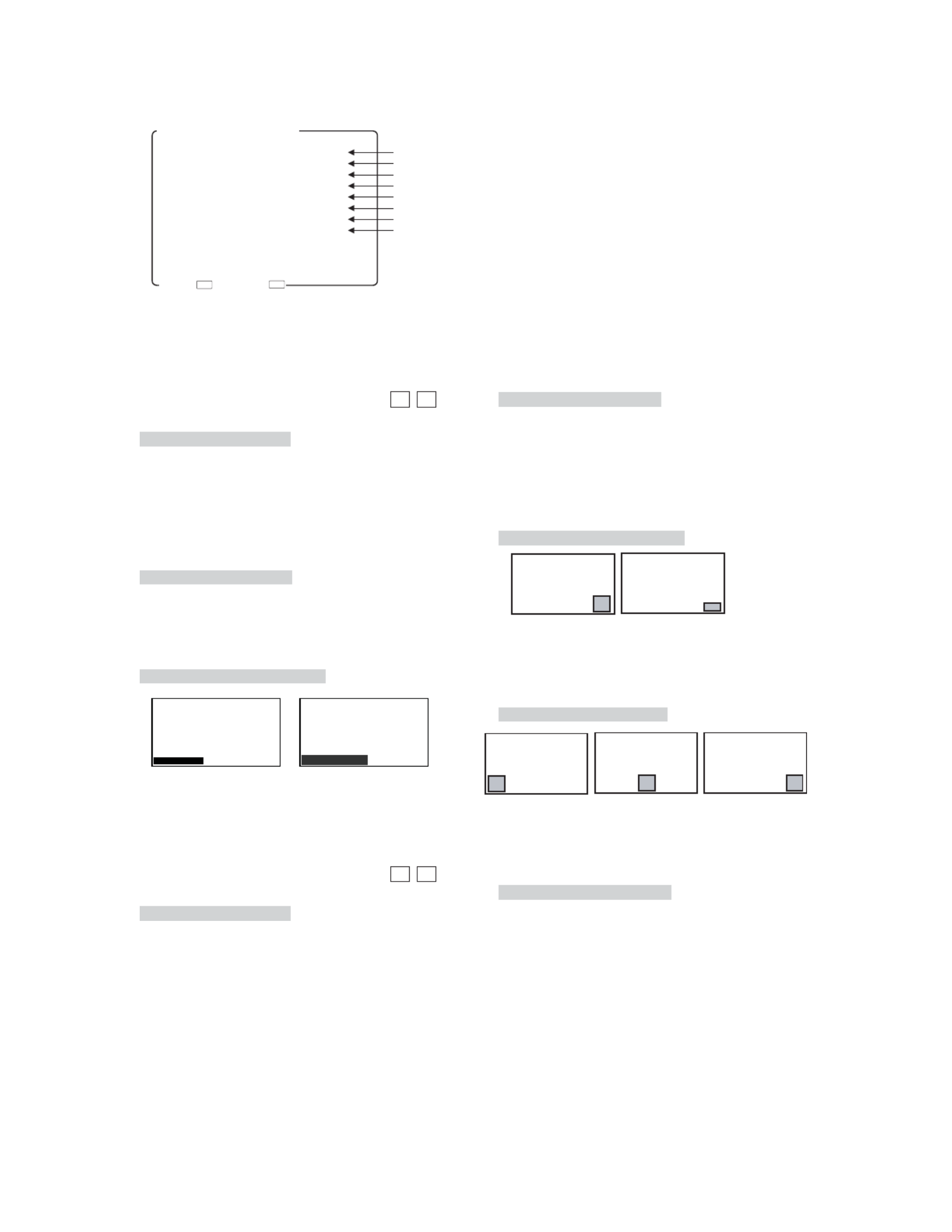
⑥ Setti i i ing the tally lamp nd cat on
Set any of the following display modes of the tally
lamps located at the top of the front of the monitor.
• R/G : R is on the left side and G on the right
side, when facing the screen.
• G/R : G is on the left side and R on the right
side, when facing the screen.
• R+G : The entire tally is displayed.
The lamp is displayed in amber when both
the R-TALLY and G-TALLY are set at ON.
Both R- and G-TALLY at ON.
• Default setting is R/G.
⑦ Setti i ing the same-s ze (dot-by-dot) d splay ON/OFF
Set to ON in order to reproduce the input signal
in its original pixels without enlargement or
reduction.
This function can be assigned with the F1 F2
switch on the front panel.
• Default setting is OFF.
* Signals in 480i/575i format are not in square
pixels. Therefore, the aspect ratio will be displayed
differently from the original image.
⑧ Setti i ing the SDI channel sw tch ng lock ON/OFF
The lock is set to "ON" to prevent SDI signal
channel switching.
It utilizes the MONITOR OUT terminal and is
effective in fixing the channel. It prevents
accidental channel switching.
• Default setting is OFF.
* Before setting it to "ON", make sure the desired
SDI channel is selected.
⑨ Setting the format d splay ON/OFF before swi itch ngi
signals
Used to set whether the channel and signal
format are displayed or not.
• Default setting is ON.
[R-TALLY ON] [G-TALLY ON]
R G
[G-TALLY ON] [R-TALLY ON]
G R
←
[Both R- and G-TALLY at ON]
←
[R-TALLY ON]
←
[G-TALLY ON]
R
G
AMBER
- 18 -
① Setti ing the SDI VITC d splay ON/OFF
Used to turn ON or OFF the VITC display
multiplexed with HD-SDI signal.
This function can be assigned with the F1 F2
switch on the front panel.
• Default setting is OFF.
* The VITC display is compatible only with the
ARIB STD-B4 Ver2.0-specified formats.
②Sett ghtnessing of SDI VITC display bri
Used to set the SDI VITC display brightness in
three levels, LOW, MID and HIGH.
• Default setting is MID.
③ Setti i ing of SDI VITC d splay s ze
Used to select the SDI VITC display size,
NORMAL or LARGE.
• Default setting is NORMAL.
④ Setti ing of waveform d splay ON/OFF
Used to turn ON or OFF the waveform display of
luminance signal.
This function can be assigned with the F1 F2
switch on the front panel.
• Default setting is OFF.
4-5 Descr pt ons. i ion of MENU 3 Functi
1.SDI VITC OFF
2.→DIMMER MID
3.→SIZE NORMAL
4.WFM DISPLAY OFF
5.→DIMMER HIGH
6.→SIZE NORMAL
7.→POSITION RIGHT
8.→COLOR WHITE
MENU3(VITC/WFM)
SET→ EXIT→
ESCEN T
①SettingtheSDIVITCdisplayON/OFF
②SettingofSDIVITCdisplaybrightness
③SettingofSDIVITCdisplaysize
④SettingofwaveformdisplayON/OFF
⑤Settingofwaveformdisplaybrightness
⑥Settingofwaveformdisplaysize
⑦Settingofwaveformdisplayposition
⑧Settingofwaveformdisplaycolor
⑤ Setti i ing of waveform d splay br ghtness
Used to set the waveform display brightness in
three levels, LOW, MID and HIGH.
• Default setting is HIGH.
⑥ Setti i ing of waveform d splay s ze
Used to set the luminance signal waveform
display size, NORMAL or SMALL.
The SMALL setting displays the waveform half
as tall as in the NORMAL setting.
• Default setting is NORMAL.
⑦ Setti i i ing of waveform d splay pos t on
Used to set the waveform display position, RIGHT,
CENTER or LEFT.
• Default setting is RIGHT.
⑧ Setti ing of waveform d splay color
Used to set the waveform display color, GREEN
or WHITE.
• Default setting is WHITE.
NORMAL
VITC00:00:00:00
LARGE
VITC00:00:00:00
SMALL
NORMAL
RIGHT CENTER
LEFT
- 19 -
① Setting the VECTOR SCOPE d splay ON/OFFi
Used to turn on or off the VECTOR SCOPE
display.
This function can be assigned with the F1 F2
switch on the front panel.
• Default setting is OFF.
②Sett ng the VECTOR SCOPE d ghtnessi isplay bri
Used to set the VECTOR SCOPE display
brightness in 3 levels: LOW, MID and HIGH.
• Default setting is HIGH.
③ Setting the VECTOR SCOPE d splay magni ifi icat on
ratio
Used to set the VECTOR SCOPE display
magnification in 4 ratios: x1, x2, p28-x4 and x8.
• Default setting is x1.
④ Setti ing the COLOR BOX scale d splay
Used to set the VECTOR SCOPE’s COLOR BOX
according to the input color bar signal: 75% and
100%.
• Default setting is 100%.
4-6 Descr pt on of MENU 4 Funct ons. i i i
⑤ Setti i i ing the VECTOR SCOPE d splay pos t on
Used to set the waveform display to any of the
RIGHT, CENTER and LEFT positions.
When used commonly with WFM, the VECTOR
display is located on the left of the WFM one.
• Default setting is RIGHT.
• RIGHT location
• CENTER location
• LEFT location
⑥ Setti ing the VECTOR SCOPE d splay color
Used to set the waveform display color to either
of GREEN and WHITE.
• Default setting is WHITE.
1.VECTOR SCOPE OFF
2.→DIMMER HIGH
3.→MAGNIFICATION ×1
4.→SCALE 100%
5.→POSITION RIGHT
6.→COLOR WHITE
SET→ EXIT→ ESCENT
①SettingtheVECTORSCOPEdisplayON/OFF
②SettingtheVECTORSCOPEdisplaybrightness
③SettingtheVECTORSCOPEdisplaymagnificationratio
④SettingtheCOLORBOXscaledisplay
⑤SettingtheVECTORSCOPEdisplayposition
⑥SettingtheVECTORSCOPEdisplaycolor
MENU4(VECTOR SCOPE)
75%SCALE 100%SCALE
VECTOR VECTOR WFM
VECTOR VECTOR WFM
VECTOR VECTOR WFM

- 21 -
4-8. Description of MENU 6 Functions
1.CHROMA GAIN UP OFF
2.IP MODE FRAME
3.H POSITION 0
4.V POSITION 0
SET→ EXIT→
ESCEN T
MENU6(VIDEO)
①Settingthechromagain-upON/OFF
②SettingtheIPconversionmode
③Adjustingthehorizontalscreenposition
④Adjustingtheverticalscreenposition
① Setting the chroma gain-up ON/OFF
Set the gain-up ON/OFF for chroma signals.
At the time of ON, the chroma gain increases by
+6 dB.
This function can be assigned with the F1 F2
switch on the front panel.
• Default setting is OFF.
② Setting the IP conversion mode
The mode for I → P conversion is set in the
1035i/1080i/1080psF/480i/575i formats.
• FRAME: The information on the previous and
subsequent fields is used to convert
images to progressive ones. Thanks to
this, diagonal interpolation of moving
images is enabled for optimum setting.
• FIELD : The line interpolation in the field is
used to convert images to progressive
ones. In this way, the signal delay can
be minimized.
• Default setting is FRAME.
* If the delay difference between video and audio
are noticeable, change to “FIELD” setting. This
setting will help operate regularly.
Compared to FRAME interpolation, the FIELD
setting may produce jaggies in moving images
viewed diagonally.
③ Adjusting the horizontal screen position
Adjust the horizontal screen position of VIDEO
input (SDI, VBS, COMP).
The settings are memorized for each channel,
each format or the setting of SYNC INT/EXT.
• Default setting is 0.
④ Adjusting the vertical screen position
Adjust the vertical screen position of VIDEO
input (SDI, VBS, COMP).
The settings are memorized for each channel,
each format or the setting of SYNC INT/EXT.
• Default setting is 0.
- 22 -
⑤ Sett ng the channel d splay of aud o level meteri i i
Set the display channel of the audio level meter.
• CH 1-2 : CH1 to CH2 is displayed.
• CH 1-4 : CH1 to CH4 is displayed.
• CH 1-8 : CH1 to CH8 is displayed.
• Default setting is CH 1-8.
⑥ Setti i ing the br ghtness of aud o level meter
Set the brightness of the audio level meter.
The level meter image transmissive mode or non-
transmissive mode can be set.
• LOW
• MID
• HIGH
• LOW (MIX) (Image transmissive mode)
• MID (MIX) (Image transmissive mode)
• HIGH (MIX) (Image transmissive mode)
• Default setting is HIGH.
4-9 Descr pt ons. i ion of MENU 7 Functi
1.LINE/SP CH. CH1/2
2.SP INPUT SEL. AUTO
3.LEVEL INDICATOR OFF
4.→MODE 1(1357−2468)
5.→CHANNEL CH 1−8
6.→DIMMER HIGH
SET→ EXIT→
ESCEN T
MENU7(AUDIO)
①Settingthechannelofembeddedaudiooutputs
②Settingthefrontspeakeroutputsignals
④Settingthemodedisplayofaudiolevelmeter
⑤Settingthechanneldisplayofaudiolevelmeter
⑥Settingthebrightnessofaudiolevelmeter
③SettingtheaudiolevelmeterdisplayON/OFF
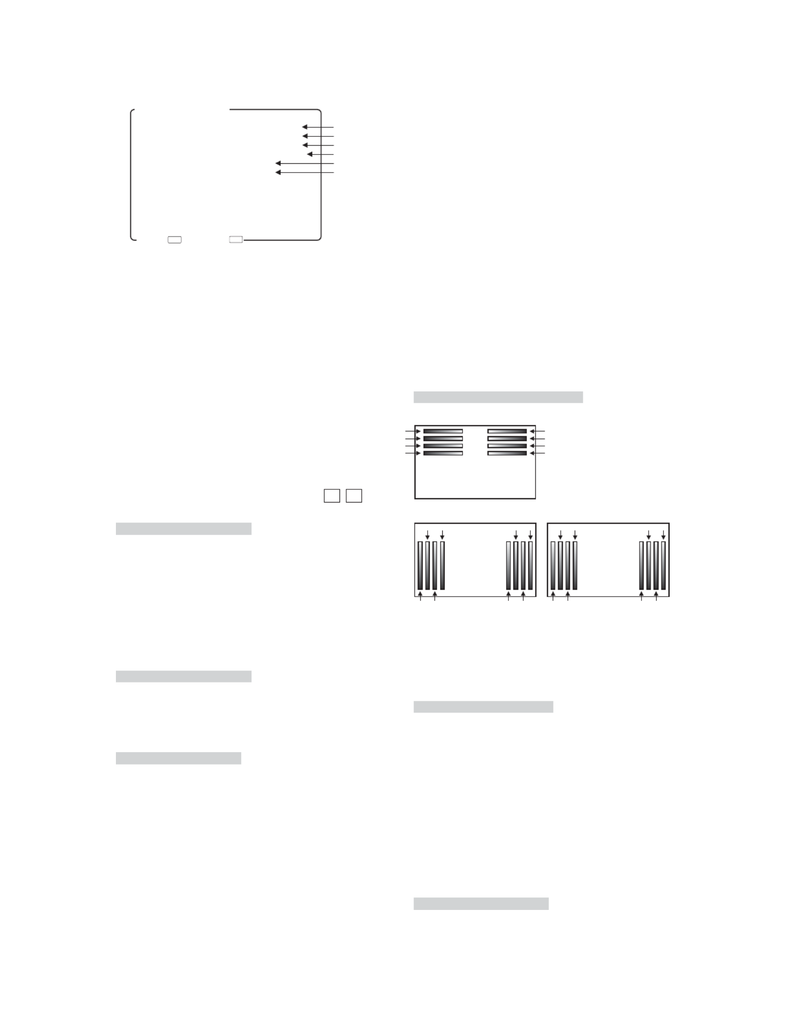
① Sett ng the channel of embedded aud o outputsi i
Set any of the following pairs of channels of
embedded audio to be outputted to the front
speaker and the rear analog output connector
(EA-240A/D3G-240A only).
• CH1/2 : The output comes out of the paired CH1
and CH2 channels.
• CH3/4 : The output comes out of the paired CH3
and CH4 channels.
• CH5/6 : The output comes out of the paired CH5
and CH6 channels.
• CH7/8 : The output comes out of the paired CH7
and CH8 channels.
This function can be assigned with the F1 F2
switch on the front panel.
• Default setting is CH1/2.
② Setti ing the front speaker output s gnals
Set the signals to be outputted to the speaker on
the front of the monitor.
•AUTO : embedded audios in the SDI input
mode, and analog in other modes
• EMBEDDED : fixed at embedded audios
• ANALOG : fixed at analog
• Default setting is AUTO.
③ Setti i ing the aud o level meter d splay ON/OFF
Used to turn on and off the audio level meter
display.
• Default setting is OFF.
④ Setti i ing the mode d splay of aud o level meter
Set the display mode of the audio level meter.
The number in parentheses shows the order of
display channel.
• 1(1357-2468) : lateral display: odd channels on
the left side of the screen, and
even channels on the right side of
the screen
• 2(1234-5678) : longitudinal display: CH1, CH2,
CH3, CH4, CH5, CH6, CH7, CH8
from left to right on the screen
• 3(1357-8642) : longitudinal display: odd
channels on the left side of the
screen, and even channels on
the right side of the screen
• Default setting is 1(1357-2468).
CH1
CH3
CH5
CH7
CH2
CH4
CH6
CH8
CH1
CH2
CH3
CH4
CH7CH5
CH6 CH8
<1(1357-2468)>
<2(1234-5678)>
CH1
CH3
CH5
CH7
CH4CH8
CH6 CH2
<3(1357-8642)>

- 23 -
4-10 Descr pt ons. i ion of MENU 8 Functi
1.MARKER(16:9) SAFETY
2.→SAFETY AREA 80%
3.→ASPECT 4:3
4.→AREA IN ASPECT 80%
5.MARKER(4:3) SAFETY
6.→SAFETY AREA 80%
7.→ASPECT 16:9
8.ASP.MARKER MODE MRK+SHD
9.→SHADOW LEVEL 40%
10.CENTER MARKER OFF
11.MARKER LEVEL 80%
↓(NEXT PAGE)
MENU8(MARKER 1/2)
SET→ EXIT→
ESCENT
⑦Settingthetypeofaspectmarker(at4:3aspectratio)
⑧Settingtheaspectmarkerdisplaymode
④Settingthesafetymarkerareainaspectmarkerarea(at16:9)
③Settingthetypeofaspectmarker(at16:9aspectratio)
②Settingthesafetymarkerarea(at16:9aspectratio)
MENU8(MARKER 2/2)
↑(BACK)
12.MARKER COLOR ■
13.USER MARKER OFF
14.SETTING EXECUTE
SET→ EXIT→
ESCENT
⑨Settingtheaspectmarkershadowlevel
⑩SettingthecentercrossmarkerON/OFF
⑪Settingthemarkerdisplaylevel
⑭Executingtheusermarkerforthedrawingsettingmenu
⑬SettingtheusermarkerdisplayON/OFF
⑫Settingthemarkerdisplaycolor
①Settingthetypeofmarker(at16:9aspectratio)
⑤Settingthetypeofmarker(at4:3aspectratio)
⑥Settingthesafetymarkerarea(at4:3aspectratio)
① Setti : ing the type of marker (at 16 9 aspect rat o)
Used to set various types of markers displayed at
16:9 aspect ratio.
• SAFETY : Displaying the safety marker preset
in Item ②.
• ASPECT : Displaying the aspect marker preset
in Item ③.
• ASP+SAF: Displaying the aspect marker preset
in Item ③ and the safety marker in
aspect marker area preset in Item ④.
• C.CROSS: Cross marker.
• CROSS5 : 5-split crosshatch pattern.
• CROSS10: 10-split crosshatch pattern.
This function can be assigned with the F1 F2 switch
on the front panel.
The types of markers can also be set with the
and switches on the front panel with no
menu displayed.
• Default setting is SAFETY.
② Setting the safety marker area (at 16 9 aspect rat: io)
Used to set the safety marker area in the 80%-
99% range with 1% increments at 16:9 aspect ratio.
SAFETY
C.CROSS CROSS10CROSS5
ASPECT ASP + SAF
Somewhere between 80% and 99% can also be set
with the
▲
and
▼
switches on the front panel
with no menu displayed.
• Default setting is 80% (safety area).
③ Setti :ng the type of aspect marker (at 16 9 aspect
rat o)i
Used to select the type of aspect marker from “4:3,
13:9, 14:9, 15:9, 1.85:1 and 2.35:1” at 16:9 aspect
ratio.
Active screen area
100% area
Variable from 80% to 99%
(1% increments)
Active screen area
Aspect marker
[4:3/13:9/14:9/15:9]
Active screen area
Aspect marker
[1.85:1 / 2.35:1]
• Default setting is 4:3 marker.

- 24 -
④ Setti ing the safety marker area n aspect marker
area (at 16:9)
Used to set the safety marker in the aspect marker
(4:3, 13:9, 14:9 and 15:9) area in the 80%-99%
range with 1% increments at 16:9 aspect ratio.
Somewhere between 80% and 99% can also be set
with the
▲
and
▼
switches on the front panel
with no menu displayed.
• Default setting is 80% (safety area).
⑤ Setti : ing the type of marker (at 4 3 aspect rat o)
Used to set various types of markers displayed
at 4:3 aspect ratio.
• SAFETY : Displaying the safety marker preset
in Item ⑥.
• ASPECT : Displaying the aspect marker preset
in Item ⑦.
• C.CROSS : Cross marker.
• CROSS5 : 5-split crosshatch pattern.
• CROSS10 : 10-split crosshatch pattern.
The types of markers can also be set with the
and switches on the front panel with no
menu displayed.
• Default setting is SAFETY.
Active screen area
Aspect marker
[4:3/13:9/14:9/15:9]
Safety marker in area,
variable from 80% to 99%
(1% increments)
C.CROSS CROSS10CROSS5
SAFETY ASPECT
⑥ Setti : ing the safety marker area (at 4 3 aspect rat o)
Used to set the safety marker area in the 80%-
99% range with 1% increments at 4:3 aspect ratio.
Somewhere between 80% and 99% can also be set
with the
▲
and
▼
switches on the front panel
with no menu displayed.
• Default setting is 80% (safety area).
⑦ Setti :ng the type of aspect marker (at 4 3 aspect
rat o)i
Used to select the type of aspect marker from “13:9,
14:9, 15:9 and 16:9” at 4:3 aspect ratio.
Active screen area (4:3)
Variable from 80% to 99%
(1% increments)
100% area
• Default setting is 16:9 marker.
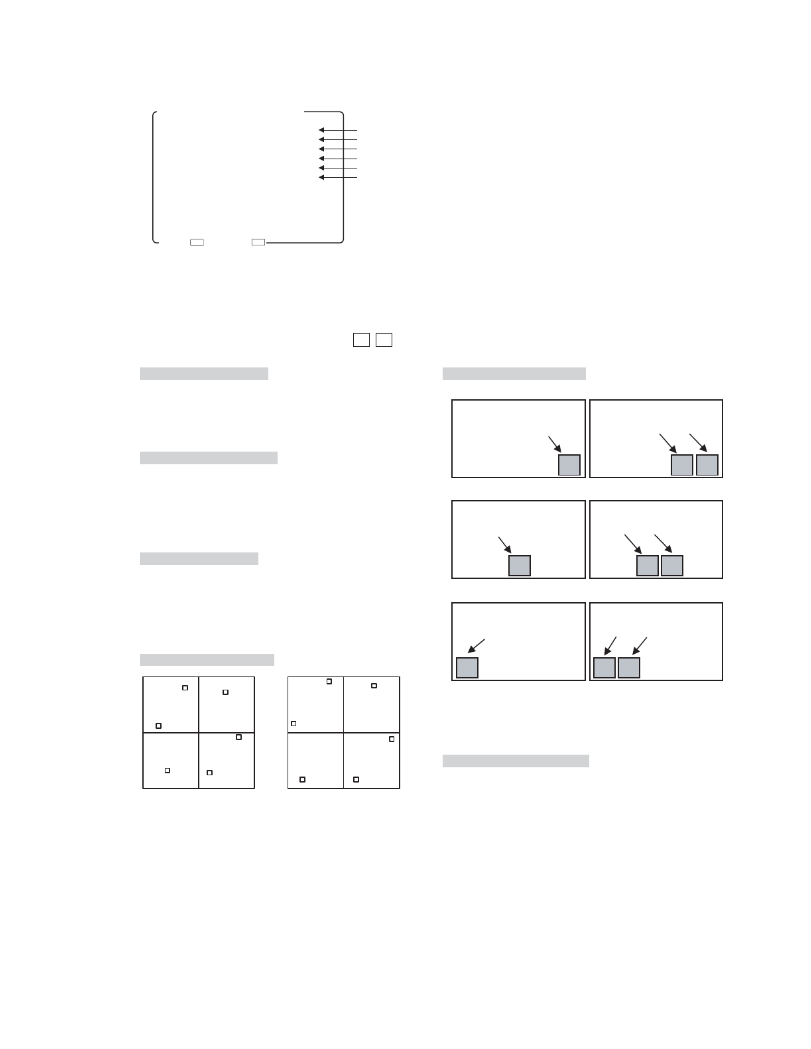
⑧ Setti ing the aspect marker d splay mode
Used to set the aspect marker display mode.
• MARKER : Displaying the marker only.
• SHADOW : Displaying the shadow only.
• MRK+SHD : Displaying both the marker and
shadow.
• Default setting is MARKER+SHADOW.
Active screen area
Aspect marker
[13:9/14:9/15:9/16:9]
SHADOWMARKER MRK+SHD
⑨ Setting the aspect marker shadow level
Used to set the contrast level of the aspect marker
shadow, when displayed.
Settings: 0%, 20%, 40% and 60%
• Default setting is 40%.
⑩ Setting the center cross marker ON/OFF
Used to turn on and off the center cross marker.
• Default setting is OFF.
OFF ON
⑪ Setti ing the marker d splay level
Used to set the marker display level.
Settings: 20%, 40%, 60%, 80% and 100%
• Default setting is 80%.
⑫ Setti ing the marker d splay color
Used to set the marker display color.
* The user marker is displayed in the color preset
on the user marker menu.
Settings : White, yellow, cyan, green, magenta,
red and blue
• Default setting is white.
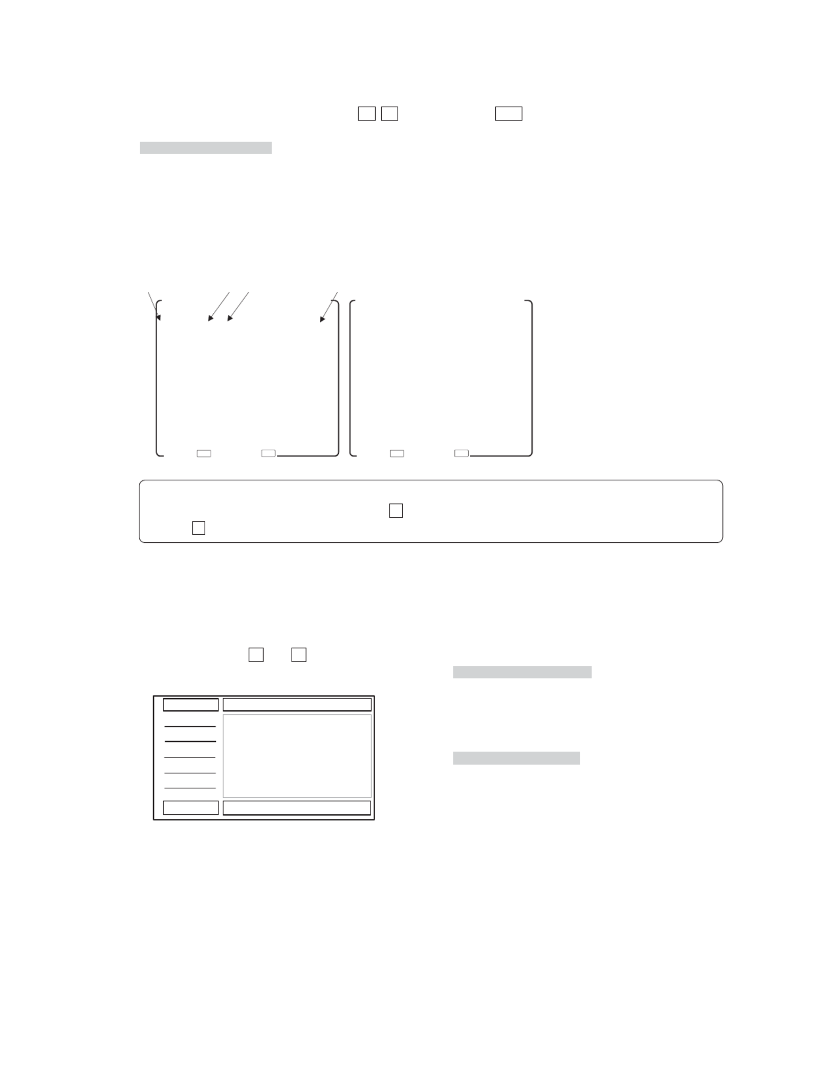
- 25 -
Setting the user marker display ON/OFF
Used to turn on and off the user marker display.
This function can be assigned with the F1 F2
switch on the front panel.
• Default setting is OFF.
Executing the user marker for the drawing setting
menu
Press ENT with EXECUTE, and the user marker
setting menu shows up. Now various settings can
be made on this menu.
For details, refer to Item 4-11.
4-11. Description of MENU8 (USER MARKER) Functions and Making Settings
PAGE1
NO. COL SW DATA(X Y)
MK1 □ ON S:−−−− −−−−
E:−−−− −−−−
MK2 □ ON S:−−−− −−−−
E:−−−− −−−−
MK3 □ ON S:−−−− −−−−
E:−−−− −−−−
MK4 □ ON S:−−−− −−−−
E:−−−− −−−−
MK5 □ ON S:−−−− −−−−
E:−−−− −−−−
↓(NEXT PAGE)
<SETTING OF USER MARKER>
①Typesofusermarkers
①NO ②COL ③SW ④DATA(X Y)
PAGE2
NO. COL SW DATA(X Y)
↑(BACK)
MK6 □ ON S:−−−− −−−−
E:−−−− −−−−
MK7 □ ON S:−−−− −−−−
E:−−−− −−−−
MK8 □ ON S:−−−− −−−−
E:−−−− −−−−
MK9 □ ON S:−−−− −−−−
E:−−−− −−−−
MK10 □ ON S:−−−− −−−−
E:−−−− −−−−
<SETTING OF USER MARKER>
úPAGE 1¸û úPAGE 2¸û
②Settingtheusermarkercolor
③SettingtheusermarkerdisplayON/OFF
④Usermarkercoordinates
SET→ EXIT→ ESC
ENT SET→ EXIT→ESC
ENT
◆ How to turn from PAGE1 to PAGE2
When the blinking cursor is at MK1, use the
▲
switch to go to PAGE2. With the blinking cursor at MK5,
use the
▼
switch to go to PAGE2.
① Types of user markers
The user markers are presettable in boxes or lines,
chosen from 10 types from MK1 to MK10. Up to
10 different display positions of subtitles can
therefore be individually preset, depending on
programs. Use the▼and▲switches to select a
desired item.
② Setting the user marker color
Using the “COL” item, select a desired display color
from 6 colors. The 10 types of user markers can be
color-coded to identify them if two or more user
markers are used.
Settings : White, yellow, cyan, green, red and blue
• Default setting is white.
③ Setting the user marker display ON/OFF
Using the “SW” item, the display can be turned on
and off.
• Default setting is ON.
<10 different display examples>

- 26 -
④ User marker coordinates
In the “DATA (X Y)” column, the coordinates for
S: START POINT END POINT and E: of the
currently set user markers are displayed.
Without such settings, the “—” marker appears.
Move the cursor to the X/Y data. Using the ENT
switch, new user markers can be drawn or already
registered user markers can be modified.
The setting can be made in 1-pixel increments. The
top left of the effective screen serves as the
reference point (0001, 0001) of the coordinates.
From this point, the coordinates can be adjusted
in the pixel range of 1920 x 1080.
• Default setting is —(unregistered).
● Resetting the data
With “DATA(X Y)” blinking in magenta, hold down
the switch (or the right-hand button on the
mouse) longer than 3 seconds. The settings of the
data can now be unregistered (—).
● Coordinate reference point
This 1920 x 1080, Full-HD panel has the pixel
reference point (0001, 0001) at the top left of the
screen. The pixel at the bottom right on screen is
preset as the coordinates (1920, 1080).
● Marker lines and coordinate values
There are 2 line widths for the user markers.
However, the coordinate for the start point and
that for the end point are different by 1 pixel.
(0001,0001)
(0001,1080) (1920,1080)
(1920,0001)
X axis
Y axis
Pixel position (X, Y) in the coordinate for the "start point"
Pixel position (X+a, Y+1) in the coordinate for the "end point"
a
Pixel position (X, Y) in the coordinate for the
"start point"
Pixel position (X+a, Y+1) in the coordinate for the
"end point"
a
Accordingly, in drawing a horizontal line, the Y-
direction address has a coordinate value with 1
pixel added, as shown below.
Line width: 2 pixels
Pixel position in the coordinate for the "start point"
Pixel position in the coordinate for the "end point"
When a vertical line is drawn, the X-axis address
has a coordinate value with 1 pixel added, as shown
below.

- 27 -
PAGE1
NO. COL SW DATA(X Y)
MK1 □ ON S:−−−− −−−−
E:−−−− −−−−
MK2 □ ON S:−−−− −−−−
E:−−−− −−−−
MK3 □ ON S:−−−− −−−−
E:−−−− −−−−
MK4 □ ON S:−−−− −−−−
E:−−−− −−−−
MK5 □ ON S:−−−− −−−−
E:−−−− −−−−
↓(NEXT PAGE)
<SETTING OF USER MARKER>
SET→ EXIT→
ESCENT
START POINT( X:0960 Y:0540)
END POINT( X:0960 Y:0540)
How to preset new user markers
START POINT( X:0300 Y:0250)
END POINT( X:0300 Y:0250)
START POINT( X:0300 Y:0250)
END POINT( X:0300 Y:0250)
START POINT( X:0300 Y:0250)
END POINT( X:1200 Y:0500)
ENT
ENT
With nothing
registered, the
cursor is
displayed at the
default center.
With nothing
registered, the
initial X-Y
coordinate is
displayed, and the
start-point X-Y
coordinate starts
blinking.
The shifted X-Y
coordinate is
displayed.
⑥ Setting the start point
⑦ Moving the cursor to the start point
⑧ Saving the start point
⑨ Moving the cursor to the end point
⑩ Saving the end point
▼
▼
▲
The end-point
X-Y coordinate
starts blinking.
Move the cursor
to the end point.
ESC
Take the
procedure to
set a new start
point.
Move the cursor
to the start point.
1.MARKER(16:9) SAFETY
2.→SAFETY AREA 80%
3.→ASPECT 4:3
4.→AREA IN ASPECT 80%
5.MARKER(4:3) SAFETY
6.→SAFETY AREA 80%
7.→ASPECT 16:9
8.ASP.MARKER MODE MRK+SHD
9.→SHADOW LEVEL 40%
10.CENTER MARKER OFF
11.MARKER LEVEL 80%
↓(NEX PAGE)
MENU8(MARKER 1/2)
SET→ EXIT→
ESCENT
MENU8(MARKER 2/2)
↑(BACK)
12.MARKER COLOR ■
13.USER MARKER ON
14.SETTING EXECUTE
SET→ EXIT→ESC
ENT
① Select MENU8
② Setting the marker display ON/OFF
MENU8(MARKER 2/2)
↑(BACK)
12.MARKER COLOR ■
13.USER MARKER ON
14.SETTING EXECUTE
SET→ EXIT→ESCENT
③ Execute the drawing mode in Item 14
④ Setting the individual markers
⑤ Going to the drawing menu
PAGE1
NO. COL SW DATA(X Y)
MK1 □ ON S:−−−− −−−−
E:−−−− −−−−
MK2 □ ON S:−−−− −−−−
E:−−−− −−−−
MK3 □ ON S:−−−− −−−−
E:−−−− −−−−
MK4 □ ON S:−−−− −−−−
E:−−−− −−−−
MK5 □ ON S:−−−− −−−−
E:−−−− −−−−
↓(NEXT PAGE)
<SETTING OF USER MARKER>
SET→ EXIT→
ESC
ENT
ENT
Move the cursor
Set USER
MARKER to ON.
Press now.ENT
Set the color and
ON/OFF display
for individual
markers.
ENT
⑥
ENT
▼
The menu screen in
Step reappears and ④
the settings are
displayed at the X-Y
coordinate.
The cursor
moves to the
start point.
Take the
procedure in
Step on the ⑥
next page.
X axis
Y axis
Move the cursor

- 28 -
PAGE1
NO. COL SW DATA(X Y)
MK1 ■ ON S:0300 0250
E:1200 0500
MK2 □ ON S:−−−− −−−−
E:−−−− −−−−
MK3 □ ON S:−−−− −−−−
E:−−−− −−−−
MK4 □ ON S:−−−− −−−−
E:−−−− −−−−
MK5 □ ON S:−−−− −−−−
E:−−−− −−−−
↓(NEXT PAGE)
<SETTING OF USER MARKER>
SET→ EXIT→
ESC
ENT
How to modify the user markers
START POINT( X:0250 Y:0200)
END POINT( X:1200 Y:0500)
START POINT( X:0250 Y:0200)
END POINT( X:1850 Y:0800)
ENT
ENT
The magenta-
colored cursor
appears at the
start point.
* If the end point
is positioned
above or to the
left of the start
point, the cursor
display position
depends on the
registered data.
⑥ Setting a new start point
⑦ Modifying the start point
⑧ Modifying the end point
⑨ Shifting the end point
⑩ Saving the end point
▼
▲
Move the cursor
to the end point.
ESC
Take the
procedure to
set a new start
point.
1.MARKER(16:9) SAFETY
2.→SAFETY AREA 80%
3.→ASPECT 4:3
4.→AREA IN ASPECT 80%
5.MARKER(4:3) SAFETY
6.→SAFETY AREA 80%
7.→ASPECT 16:9
8.ASP.MARKER MODE MRK+SHD
9.→SHADOW LEVEL 40%
10.CENTER MARKER OFF
11.MARKER LEVEL 80%
↓(NEX PAGE)
MENU8(MARKER 1/2)
SET→ EXIT→
ESCENT
MENU8(MARKER 2/2)
↑(BACK)
12.MARKER COLOR ■
13.USER MARKER ON
14.SETTING EXECUTE
SET→ EXIT→
ESCENT
① Select MENU8
② Setting the marker display ON/OFF
MENU8(MARKER 2/2)
↑(BACK)
12.MARKER COLOR ■
13.USER MARKER ON
14.SETTING EXECUTE
SET→ EXIT→
ESCENT
③ Execute the drawing mode in Item 14
④ Setting the individual markers
⑤ Setting the modified size
PAGE1
NO. COL SW DATA(X Y)
MK1 □ ON S:0300 0250
E:1200 0500
MK2 □ ON S:−−−− −−−−
E:−−−− −−−−
MK3 □ ON S:−−−− −−−−
E:−−−− −−−−
MK4 □ ON S:−−−− −−−−
E:−−−− −−−−
MK5 □ ON S:−−−− −−−−
E:−−−− −−−−
↓(NEXT PAGE)
<SETTING OF USER MARKER>
SET→ EXIT→
ESCENT
ENT
Set USER
MARKER to ON.
Press now.ENT
Set the color and
ON/OFF display
for individual
markers.
ENT
ENT
START POINT( X:0300 Y:0250)
END POINT( X:1200 Y:0500)
START POINT( X:0250 Y:0200)
END POINT( X:1200 Y:0500)
Move the cursor
to the start point.
The shifted X-Y
coordinate is
displayed.
The end-point
X-Y coordinate
starts blinking.
The magenta-
colored cursor
appears at the
end point.
▼
▼
X axis
Y axis
The menu screen in
Step reappears ④
and the new settings
are displayed at the
X-Ycoordinate.
The start-point
X-Y coordinate
starts blinking.
⑥
Hold down the switch (or
the right-hand button on the
mouse), and the data will be
initialized ( ).
(Hold down)
▼
▼
Move the cursor
Move the cursor
The cursor
moves to the
start point.

- 29 -
4-12 Descr pt ons. i ion of MENU 9 Functi
① Setti i ing the funct ons of parallel remote p ns
Select the pre-assigned pin functions of parallel
remote control or the individual user-set functions.
* By default, the pre-assigned pin functions are
displayed beneath.
② Setti ing the IP convers on mode
When “USER” is selected in ①, set the
individual pin functions.The settable functions
are as follows.
• CH-B : selection of CH-B
• SDI : selection of SDI input
• DVI : selection of DVI input
• COMP. : selection of component input
• MONO : selection of MONO
• RGB : selection of component RGB input
• 16:9 : selection of SDTV aspect ratio
16:9
• EXT SYNC : selection of external sync input
• MARKER : marker ON
• SHADOW : shadow ON at MENU7-preset
level
• SHADOW0 : shadow ON at shadow level 0%
(Black)
• SHADOW20 : shadow ON at shadow level 20%
• SHADOW40 : shadow ON at shadow level 40%
• SHADOW60 : shadow ON at shadow level 60%
• R-TALLY : R tally ON
• G-TALLY : G tally ON
• (blank) : unassigned
* “SHADOW0 ”, “SHADOW20 ”, “SHADOW40 ” and
“SHADOW60 ” functions
• Select two or more SHADOW settings at once,
and “SHADOW0” (Black) is given priority.
• When any of these functions is turned ON, the
MENU8-adjusted shadow level is forced to go
back to the level remotely preset.
* The functions of the following pins, which are fixed,
cannot be changed.
• Pin 1 : Make contact GND
MENU9(PARALLEL REMOTE)
1.PIN FUNCTION DEFAULT
P2:CH−B P9 :EXT SYNC
P3:(blank) P10:16:9
P4:G−TALLY P11:DVI
P5:COMP. P12:MARKER
P6:(blank) P13:SHADOW
P7:MONO P14:R−TALLY
P8:RGB P15:SDI
(P1:GND)
①Settingthefunctionsofparallelremotepins
②Settingtheuserpinfunctions
SET→ EXIT→
ESCE NT

- 30 -
* The settings on MENU10 can be made only when the PC input is selected.
* When the computer screen resolution is set at WXGA, SXGA, UXGA and WUXGA, be sure to select the refresh
frequency of 60 Hz.
① Setting the d splay mode w th DVI i i input (PC format)
Used to preset the image display size in receiving
the PC-format DVI signals. This is effective when
a DVI input mode has been selected and the related
signal is detected.
• REAL : Images are displayed 1 : 1 with the
resolution of input signal.
• NORMAL : With the aspect ratio intact, images
are enlarged or reduced in this
panel’s maximum displayable size.
• FULL : Images are fully displayed onscreen
(1920 x 1080) for all input signals.
• Default setting is NORMAL.
◆Display pixels with respect to PC input signals in each
mode
② Swi i tch ng between analog PC and COMPONENT
i i input s gnals (Sett ngs only for the CM-240)
PC : Analog PC input of the CM-240 is
selected.
VIDEO : COMPONENT input of the CM-240 is
selected.
This function can be assigned with the F1 F2 switch
on the front panel.
• Default setting is VIDEO.
③ Setti i i ing the d splay mode w th analog PC nput
(Settings only for the CM-240)
Used to preset the image display size. The table
below Item ① is also applicable with the display
pixel size with respect to the input signal mode.
• REAL : Images are displayed 1 : 1 with the
resolution of input signal.
• NORMAL : With the aspect ratio intact, images
are en larged or reduced in this
panel’s maximum displayable size.
• FULL : Images are fully displayed onscreen
(1920 x 1080).
• Default setting is NORMAL.
4-13 Descr pt ons. i ion of MENU 10 Functi
⑧AdjustingtheclockwithanalogPCinput(SettingsonlyfortheCM-240)
⑤ExecutingtheautomaticadjustmentofPCinput(OnlyfortheDVI(PC)andCM-240)
MENU10(PC SETUP)
SET→ EXIT→
ESC
EN T
1.DVI SETUP
2.→EXPANSION NORMAL
3.COMP SETUP
4.→INPUT SELECT VIDEO
5.→EXPANSION NORMAL
6.→XGA/WXGA XGA
7.AUTO ADJUST EXECUTE
8.→H POSITION 0
9.→V POSITION 0
10.→CLOCK 0
11.→PHASE 0
①SettingthedisplaymodewithDVIinput(PCformat)
③SettingthedisplaymodewithanalogPCinput(SettingsonlyfortheCM-240)
④SelectingtheanalogPCinputXGA/WXGA(SettingsonlyfortheCM-240)
⑨AdjustingthephasewithanalogPCinput(SettingsonlyfortheCM-240)
⑦AdjustingtheverticalonscreenpositionwithPCinput(OnlyfortheDVI(PC)andCM-240)
⑥AdjustingthehorizontalonscreenpositionwithPCinput(OnlyfortheDVI(PC)andCM-240)
②SwitchingbetweenanalogPCandCOMPONENTinputsignals(SettingsonlyfortheCM-240)
Pixel size and aspect ratioPC input signal
(pixels, aspect ratio) REAL NORMAL FULL
VGA
(640 ×480 , 4:3)
640 ×480
(4:3)
1440×1080
(4:3)
1920×1080
(16:9)
SVGA
(800 ×600 , 4:3)
800 ×600
(4:3)
1440×1080
(4:3)
1920×1080
(16:9)
XGA
(1024 ×768 , 4:3)
1024×768
(4:3)
1440×1080
(4:3)
1920×1080
(16:9)
WXGA
(1280 ×768 , 15:9)
1280×768
(15:9)
1800×1080
(15:9)
1920×1080
(16:9)
SXGA
(1280 ×1024 , 5:4)
1280×1024
(5:4)
1350×1080
(5:4)
1920×1080
(16:9)
UXGA
(1600 ×1200 , 4:3)
1600×1080
(4:3)
1440×1080
(4:3)
1920×1080
(16:9)
WUX GA
(1920 ×1200 , 16:1 0)
1920×1080
(16:10)
1728×1080
(16:10)
1920×1080
(16:9)
<REAL display mode with UXGA signal>
Onscreen display area
(1080 pixels)
Input signal
(1200 pixels)
Onscreen display area
(1080 pixels)
Input signal
(1200 pixels)
Onscreen display area
(1920 pixels)
<REAL display mode with WUXGA signal>
*1:In the REAL display mode with UXGA/WUXGA
signals, the input signal’s number of vertical pixels
(1200 pixels) is greater than the display panel’s
number of corresponding pixels (1080 pixels). As
shown below, therefore, the 120-pixel images are
cut off on screen at the top and bottom.

- 31 -
④ Selecti ing the analog PC nput XGA/WXGA
(Settings only for the CM-240)
When the analog PC input signal is WXGA, the
format may fail to be identified, depending on the
signal timing. In such case, select WXGA.
• Default setting is XGA.
⑤ Executi i ing the automat c adjustment of PC nput
(Only for the DVI(PC) and CM-240)
Used to automatically adjust the phase, clock and
horizontal/vertical onscreen position in Items ⑥
thru ⑨.
With the “EXECUTE” characters blinking, press
the ENT switch, and the automatic adjustment
will be made.
* During the automatic adjustment, do not turn
off the power and switch the input signal.
⑥ Adjusting the hor zontal onscreen posi iti ion w th PC
input (Only for the DVI(PC) and CM-240)
Used to adjust the horizontal onscreen position.
⑦ Adjusti i i i ing the vert cal onscreen pos t on w th PC
input (Only for the DVI(PC) and CM-240)
Used to adjust the vertical onscreen position.
⑧ Adjusti i i ing the clock w th analog PC nput (Sett ngs
only for the CM-240)
Used to adjust if noticeable vertical stripes appear
onscreen.
⑨ Adjusti i ing the phase w th analog PC nput
(Settings only for the CM-240)
Used to adjust if horizontal stripes appear or the
characters look blurry onscreen.
4-14 Descr pt. i ion of MENU 11 Functions
① Executi i i i i ing the n t al zat on of set data
Perform this setting to restore the default settings.
• ALL : Factory settings are restored for
all PRESET data, all MENUs
and switches.
• PRESET : Factory settings are restored for
all PRESET data.
• MENU&SW : Factory settings are restored for
all MENUs and switches.
To initialize, select an item to be initialized with
the
▲
and
▼
switches and press the ENT switch.
The confirmation message appears. Press the ENT
switch again. To cancel the initialization, just press
the ESC switch.
* The initialization of data cannot be executed if
“DATA LOCK” or “ALL LOCK” is set in "5-2. ⑥
Setting of data protection password".
To initialize the data,unlock.
② Select ng the preset f les to be n t al zedi i i i i i
When “PRESET ” is selected in ①, select a file
for restoring the set data to the factory-set one.
• ALL : All the preset files are initialized.
• FILEx : FILEx only is initialized.
(x:1 to 8)
• FILE 1-8: FILE1 to FILE8 only are initialized.
• D65 : REF D65 only is initialized.
• D93 : REF D93 only is initialized.
• D65/D93 : REF D65 and D93 only are initialized.
1.LOAD FACTORY ALL
2.RESET FILE ALL
MENU11(RESET)
SET→ EXIT→
ESCEN T
①Executingtheinitializationofsetdata
②Selectingthepresetfilestobeinitialized

- 32 -
① Di i isplay ng the MPU vers on
Displays the current software version.
② Di i i isplay ng the work ng t me
The total working time of the monitor is displayed
in hours.
③ Di i isplay ng the opt onal modules mounted
Displays the optional module currently mounted
on the monitor.
The following message appears when no
corresponding optional module is installed.
“ NO OPTION”
The following appear when an optional module is
installed.
CM-240: When equipped with the CM-240.
EA-240A: When equipped with the EA-240A.
EA-240D: When equipped with the EA-240D.
D3G-240A: When equipped with the D3G-240A.
D3G-240D:When equipped with the D3G-240D.
4-15 Descr pt on of MENU 12 Funct ons. i i i
Wri i it ng from mon tor to USB memory
① Sett ng the date of a f le to be wr tten on USBi i i
memory
Used to set the editing date of a file to be written
on a USB memory. Enter a date when you are going
to write on the USB memory. When reviewing files
on a computer, the date entered here will be
displayed as the date of the file.
Enter “Y (year)/M (month)/D (day)” in this order.
If no date is entered, the file will be edited as of
the date appearing currently on the menu.
② Sett ng the t me of a f le to be wr tten on USBi i i i
memory
Used to set the editing time of a file in a way similar
to Item ①.
Enter “H (hour) : M (minute)” in this order.
If no time is entered, the file will be edited as of
the time appearing currently on the menu.
4-16 Descr pt on of MENU 13 Funct ons. i i i
③Displayingtheoptionalmodulesmounted
①DisplayingtheMPUversion
②Displayingtheworkingtime
1.MPU VERSION 01.00
2.WORKING TIME 50H
3.OPTION MODULE
→ NO OPTION
MENU12(INFORMATION)
SET→ EXIT→
ESCEN T
<MONITOR → USB MEMORY>
1.SETTING OF DATE & TIME
2.→DATE Y/M/D 08/01/01
3.→TIME H:M 00:00
4.WRITE TO MEM EXECUTE
<USB MEMORY → MONITOR>
5.CONTENTS TO DOWNLOAD
□MENU&SW
□USER MARKER 1〜10
□PRESET
6.DOWNLOAD EXECUTE
MENU13(USB MEMORY)
SET→ EXIT→ESC
EN T
①SettingthedateofafiletobewrittenonUSBmemory
②SettingthetimeofafiletobewrittenonUSBmemory
③WritingtoUSBmemory
④Selectingitemstobedownloaded
a)MENU&SW:Settingdataofmenusandswitches.
b)USERMARKER:Settingdataofusermarkers.
c)PRESET:Variouspresetdata.
⑤Executingthedownloading

- 33 -
③ Writing to USB memory
To write all the setting data from the monitor to
a USB memory, select “EXECUTE” and press
the ENT switch. For writing details, refer to
“How to write from monitor to USB memory”
(page 35).
File format for writing to USB memory
Files to be written from the monitor to a USB
memory are created in the following 3 text files
in the Ikegami Monitor folder that is
automatically prepared.
◆ Precauti i ions on wr t ng
With a USB memory connected, do not turn on
and off the monitor power. Do not draw out the
inserted USB memory while the writing is going
on. Otherwise the USB memory may get
damaged. Draw out the USB memory in the steps
according to “How to write from monitor to USB
memory” (page 35) discussed later.
Do not change the name of an automatically
prepared folder or a file. Otherwise downloading
to the monitor cannot be carried out. Do not
modify the data of a file either. In such case, the
data order may change and the data may fail to
be written.
If there is a file already in the specified folder,
the data of a new file will be overwritten on the
existing file.
High-security USB memories could not be
possibly recognized.
Downloading from USB memory to monitor
④ Selecting items to be downloaded
Select the items of data to be downloaded from
the USB memory to the monitor. Tick the check
box.
Items
a) □ MENU&SW
• Tick this check box to download the status of
all the menus (USER MARKER MENU and
PRESET MENU not included) and the switch
settings.
• The “¥Ikegami Monitor¥menu sw 001.txt” file
can be read.
• Files are common for the HLM-2450W and
HLM-3250W. The data saved from the HLM-
2450W may be downloaded to the HLM-3250W,
and vice versa.
b) □ USER MARKER
• Tick this check box to download various settings
(color, ON/OFF, X-Y coordinate) of the user
markers MK1 thru MK10 that are preset in
MENU8.
• The “¥Ikegami Monitor¥user marker 001.txt”
file can be downloaded.
• By changing the “MK1 thru MK10” settings,
the user markers can be downloaded in groups
or individually.
• Files are common for the HLM-2450W and
HLM-3250W. The data saved from the HLM-
2450W may be downloaded to the HLM-3250W,
and vice versa.
Ikegam _Mon tor i i
menu_sw_001.txt
・Filetosavethemenu(USERMARKERand
PRESETMENUnotincluded)statusandthe
switchsettings.
・Datacapacity:Approx.2Kbye
・FilescommonfortheHLM-2450Wand
HLM-3250W.
user_marker_001.txt
・Filetosavevarioussettingdataoftheuser
markersMK1thruMK10thatarepresetin
MENU8.
・Datacapacity:Approx.2Kbye
・FilescommonfortheHLM-2450Wand
HLM-3250W.
preset_hlm3250_001.txt
・FiletosavethePRESETmenusettingsas
wellasalltheD65,D93andFILE1thru-8
data.
Thepasswordlockandthepassworditself
arenotsaved,however.
・Datacapacity:Approx.3Kbye
・ThisfileisspecificfortheHLM-3250W.
ThePRESETdataoftheHLM-2450Wand
othermodelscannotbedownloaded.
:Automaticallypreparedfolders

- 37 -
5. Preset Menu Function
5-1. List of preset menu
To execute the preset menu, press PRESET .
* Turn off the menu screen.
5-2. Description of preset menu
① Selection of files
Select a file from among D65, D93 and FILE1 to
FILE8.
D65 : 6500K
D93 : 9300K
FILE 1-8 : User-edited files
The following data is memorized on these 10 files.
• HUE : Hue data (only for NTSC signals)
• CHROMA : CHROMAdata
• BRIGHT : BRIGHTNESS data
• CONT : CONTRAST data
• R.GAIN : R.GAIN data
• G.GAIN : G.GAIN data
• B.GAIN : B.GAIN data
• R.BKG : R.BACKGROUND data
• G.BKG : G.BACKGROUND data
• B.BKG : B.BACKGROUND data
• GAMMA : Gamma data
• APT LEVEL : Aperture level
• APT FREQ. : Aperture frequency
The DS65 and D93 have been factory-set for the
color temperatures of 6500K and 9300K,
respectively. The FILE1 thru -8 data have been
factory-set to be the same as for the D65.
(PRESET MENU)
.SELECT FILE D
.CHANGE DATA
.DISPLAY STATUS
.COPY FILE
.CHANGE FILE AUTO
.LOCK FILE/DATA
ENTER→ EXIT→
(CHANGE DATA):D
1.HUE
. CHROMA
. BRIGHT
. CONT
. R.BKG
. G.BKG
. B.BKG
. R.GAIN
. G.GAIN
10. BGAIN
11. GAMMA
12. APT LEVEL
13. APT FREQ.HIGH
SET→ END→
(PRESET DATA STATUS)
SELECT FILED
1.HUE
2.CHROMA
3.BRIGHT
4.CONT
5.R.BKG
6.G.BKG
7.B.BKG
8.R.GAIN
9.G.GAIN
10. B.GAIN
11. GAMMA
12. APT LEVEL
13. APT FREQ.HIGH
EXIT→
(COPY FILE)
FROM : D
↓
TO : FILE
SET→ EXIT→
E SC
(LOCK FILE/DATA)
STATUS:UNLOCK
−ENTER PASSWORD−
ABCDEFGHIJKLMNOPQRSTUVWXYZ
PASSWORD
SET→ EXIT→
2. CHANGE DATA 3. DISPLAY STATUS 6. LOCK FILE/DATA4. COPY FILE

- 38 -
② Change of preset data
Change the data of a file selected in "(a) Selection
of files" on the preceding page.
How to change data
Select “CHANGE DATA” and press the ENT
switch. The following “CHANGE DATA” menu
appears.
Adjustable
• HUE
Used to set the hue (only for NTSC signals).
• CHROMA
Used to set the color density.
• BRIGHT (BRIGHTNESS)
Used to set the black level.
• CONT (CONTRAST)
Used to set the white level.
• R.BKG (R.BACKGROUND)
Used to set the black balance (red component) in
the dark zone.
• G.BKG (G.BACKGROUND)
Used to set the black balance (green component)
in the dark zone.
• B.BKG (B.BACKGROUND)
Used to set the black balance (blue component)
in the dark zone.
• R.GAIN
Used to set the white balance (red component) in
the bright zone.
• G.GAIN
Used to set the white balance (green component)
in the bright zone.
• B.GAIN
Used to set the white balance (blue component)
in the bright zone.
• GAMMA
Used to set the gamma level in the “1.4-3.0”
range.
• Default setting is 2.2.
• APT LEVEL
Used to set the aperture level in the “0-63” range.
• Default setting is 16.
• APT FREQ.
Used to set the aperture frequency.
LOW (low frequency), MID1, MID2, HIGH (high
frequency)
• Default setting is HIGH.
(CHANGE DATA):D65
1. HUE 0
2. CHROMA 0
3. BRIGHT 0
4. CONT 0
5. R.BKG 0
6. G.BKG 0
7. B.BKG 0
8. R.GAIN 0
9. G.GAIN 0
10. B.GAIN 0
11. GAMMA 2.2
12. APT LEVEL 16
13. APT FREQ. HIGH
SET→ END→
ESC
(a)
File being selected
(b)
HUE data
(c) CHROMA data
(d) BRIGHT data
(e) CONTRAST data
(f) R. BACKGROUND data
(g) G. BACKGROUND data
(h) B. BACKGROUND data
(i) R.GAIN data
(j) G.GAIN data
(k) B.GAIN data
(l)
Gamma data
(m)
Aperture level
(n)
Aperture frequency
EN T
(CHANGE DATA):FILE1
1. HUE 0
2. CHROMA 0
3. BRIGHT 0
4. CONT 0
5. R.BKG 0
6. G.BKG 0
7. B.BKG 0
8. R.GAIN 0
9. G.GAIN 0
B.GAIN 0
GAMMA 2.2
APT LEVEL 16
APT FREQ. HIGH
SET→ END→
ESCE N T
▼
▲
(CHANGE DATA):D65
1. HUE 0
2. CHROMA 0
3. BRIGHT 0
4. CONT 0
5. R.BKG +10
6. G.BKG 0
7. B.BKG 0
8. R.GAIN 0
9. G.GAIN 0
B.GAIN 0
GAMMA 2.2
APT LEVEL 16
APT FREQ. HIGH
SAVE→ CANCEL→
ESCE N T
ESC
(CHANGE DATA):D65
1. HUE 0
2. CHROMA 0
3. BRIGHT 0
4. CONT 0
5. R.BKG +10
6. G.BKG 0
7. B.BKG 0
8. R.GAIN 0
9. G.GAIN 0
10.
B.GAIN 0
11.
GAMMA 2.2
12.
APT LEVEL 16
13.
10.
11.
12.
13.
10.
11.
12.
13.
10.
11.
12.
13.
APT FREQ. HIGH
DATA SAVE
ENT
(CHANGE DATA):D65
1.HUE 0
2.CHROMA 0
3.BRIGHT 0
4.CONT 0
5.R.BKG 0
6.G.BKG 0
7.B.BKG 0
8.R.GAIN 0
9.G.GAIN 0
10
. B.GAIN 0
11
. GAMMA 2.2
12
. APT LEVEL 16
13
. APT FREQ. HIGH
DATA CLEAR
Change of PRESETdata
FILE1
5.R.BKG 0
▼
▼
FILE1
5.R.BKG −5
▼
▲
▼
FILE1
5.R.BKG −5
(CHANGE DATA):FILE1
1.HUE 0
2.CHROMA 0
3.BRIGHT 0
4.CONT 0
5.R.BKG −5
6.G.BKG 0
7.B.BKG 0
8.R.GAIN 0
9.G.GAIN 0
B.GAIN 0
GAMMA 2.2
APT LEVEL 16
APT FREQ. HIGH
SET→ END→
ESC
E N T
ESC
ESC
FILE1
7.B.BKG 0
▼
ENT
ENT
Move the cursor to the
sett ng to mod fy.i i
Only the current f le name i
and the tem to mod fy are i i
d splayed here.i
The tem to change ts i i
sett ng can be selected i
here.
In th s menu status, the i
cursor can be moved to an
i i item to remod fy ts
sett ng.i
To end the change of data,
go to the "DATA SAVE"
or "DATA CLEAR" menu.
Change the
sett ng.i
To reg ster the data at th s i i
po nt, press the iENT
sw tch. To restore the i
prev ous data, press the i
ESC sw tch.i
Data
reg sterediData cleared

- 39 -
③ Di isplay of preset data l st
▲
▲
(a) Select the copy source file (D65, D93, FILEx [x: 1
to 8]) using the
▲
/
▼
switch and press the ENT
switch.
(b) Select the copy destination file (FILEx [x: 1 to 8],
FILE1 - FILE8) using the
▲
/
▼
switch.
* When FILE1 - FILE8 are selected, data is copied
to FILE1 through FILE8.
(c) When the switch is pressed, the copyENT
confirmation message appears. To copy, press the
ENT ESC switch again. If not, press the switch.
⑤ Setti i i ing of f le change operat on at the t me of
channel change
Set the association of channel change with file
change.
• AUTO : Files are memorized for each channel:
When a channel is changed to
another, an automatically stored file
is picked up.
• MANUAL: Just one file preset for all channels
is fixed.
• Default setting is AUTO.
Display a list of the settings of file data.
To change files, use the and switches at the
SELECT FILE setting.
④ Copyi ing of f le data
(PRESET DATA STATUS)
SELECT FILE D65
1. HUE 0
2. CHROMA 0
3. BRIGHT 0
4. CONT 0
5. R.BKG 0
6. G.BKG 0
7. B.BKG 0
8. R.GAIN 0
9. G.GAIN 0
10. B.GAIN 0
11. GAMMA 2.2
12. APT LEVEL 16
13. APT FREQ. HIGH
EXIT→
ESC
(a) File being selected
(b) HUE data
(c) CHROMA data
(d) BRIGHT data
(e) CONTRAST data
(f) R. BACKGROUND data
(g) G. BACKGROUND data
(h) B. BACKGROUND data
(i) R.GAIN data
(j) G.GAIN data
(k) B.GAIN data
(l) Gamma data
(m) Aperture level
(n) Aperture frequency
ENT
(COPY FILE)
FROM : D65
↓
TO : FILE1
SET→ EXIT→
ESC
(a) Selection of copy
source file
(b) Selection of copy
destination file
⑥ Setti ing of data protect on password
A password is set to prevent modifications of the
preset data and the initialization.
(a)Display of currently set lock mode
• The currently set lock mode is displayed.
•UNLOCK : The lock is released and all
data can be changed.
•DATA LOCK: Preset data change is locked,
a l th oug h file c hang e i s
possible.
•ALL LOCK : Preset data change and file
change are impossible.
(b)Password menu
• Select characters from this list using the
▲
,
▼
, and switches and press the ENT
switch to set the password.
(c) Password entry
• When setting the lock mode to ALL LOCK or
DATA LOCK or when releasing the lock mode
(UNLOCK), select characters from the menu
in ② and enter a four-digit password here.
* If you forget the registered password, contact
Ikegami’s service office. They have a password
for releasing the lock.
(d)Setting of LOCK mode
• When the switch is pressed after theENT
password has been entered, the LOCK mode
blinks. Execute the setting by pressing the
ENT key. To return to the previous state, press
the ESC switch.
(LOCK FILE/DATA)
STATUS:UNLOCK
−ENTER PASSWORD−
ABCDEFGHIJKLMNOPQRSTUVWXYZ
123456789
PASSWORD ****
SET→ EXIT→
ESCENT
(LOCK FILE/DATA)
STATUS:UNLOCK
−ENTER PASSWORD−
ABCDEFGHIJKLMNOPQRSTUVWXYZ
123456789
PASSWORD ABCD
MODE ALL LOCK
SET→ CANCEL→
ESCENT
(a)
Display of currently
set lock mode
(b) Password
menu
(c)
Password entry
(d)
Setting of lock
mode
▲
▲

- 40 -
▼
▲
ESC
ENT
(LOCK FILE/DATA)
STATUS:UNLOCK
−ENTER PASSWORD−
ABCDEFGHIJKLMNOPQRSTUVWXYZ
123456789
PASSWORD ****
SET→ EXIT→ESC
ENT
(LOCK FILE/DATA)
STATUS:UNLOCK
−ENTER PASSWORD−
ABCDEFGHIJKLMNOPQRSTUVWXYZ
123456789
PASSWORD ABCD
MODE UNLOCK
SET→ CANCEL→ ESCENT
(LOCK FILE/DATA)
STATUS:UNLOCK
−ENTER PASSWORD−
ABCDEFGHIJKLMNOPQRSTUVWXYZ
123456789
PASSWORD ABCD
MODE ALL LOCK
SET→ CANCEL→ ESC
ENT
(LOCK FILE/DATA)
STATUS:ALL LOCK
−ENTER PASSWORD−
ABCDEFGHIJKLMNOPQRSTUVWXYZ
123456789
PASSWORD ****
SET→ EXIT→ESC
ENT
ENT
(LOCK FILE/DATA)
STATUS:UNLOCK
−ENTER PASSWORD−
ABCDEFGHIJKLMNOPQRSTUVWXYZ
123456789
PASSWORD ****
SET→ EXIT→ESC
ENT
Changing the lock mode
Select a character
with the cross
switch, and enter a
4-character
password.
With the 4-
character password
entered, the
lock/unlock mode
status appears.
Press the ENT
switch, and the
password is
registered in the
selected lock
mode.
Press the ESC
switch, and the
lock mode is
undone and the
previous setting is
restored.
Select the lock
mode.
Termékspecifikációk
| Márka: | Ikegami |
| Kategória: | Monitor |
| Modell: | HLM-3250W |
Szüksége van segítségre?
Ha segítségre van szüksége Ikegami HLM-3250W, tegyen fel kérdést alább, és más felhasználók válaszolnak Önnek
Útmutatók Monitor Ikegami

27 Augusztus 2024
27 Augusztus 2024
27 Augusztus 2024
27 Augusztus 2024
Útmutatók Monitor
- Monitor Samsung
- Monitor PeakTech
- Monitor Sony
- Monitor Yamaha
- Monitor Fujitsu
- Monitor Acer
- Monitor LG
- Monitor Philips
- Monitor Pioneer
- Monitor Olympus
- Monitor SilverCrest
- Monitor Garmin
- Monitor RCF
- Monitor Bosch
- Monitor Panasonic
- Monitor Canon
- Monitor JVC
- Monitor Sharp
- Monitor Lenovo
- Monitor HyperX
- Monitor Toshiba
- Monitor Neumann
- Monitor Omron
- Monitor HP
- Monitor Hyundai
- Monitor Hisense
- Monitor BenQ
- Monitor Apple
- Monitor Emos
- Monitor Medion
- Monitor Vimar
- Monitor JBL
- Monitor TCL
- Monitor OSEE
- Monitor Viessmann
- Monitor Insignia
- Monitor LC-Power
- Monitor Dell
- Monitor Boss
- Monitor Crestron
- Monitor Gigabyte
- Monitor Tripp Lite
- Monitor Xerox
- Monitor Thomson
- Monitor Speco Technologies
- Monitor Hikvision
- Monitor Eurolite
- Monitor Epson
- Monitor V7
- Monitor Huawei
- Monitor Asus
- Monitor PEAQ
- Monitor Renkforce
- Monitor Haier
- Monitor Mitsubishi
- Monitor M-Audio
- Monitor AOC
- Monitor Citizen
- Monitor Westinghouse
- Monitor Hitachi
- Monitor Continental Edison
- Monitor Asrock
- Monitor Ring
- Monitor Alpine
- Monitor Optoma
- Monitor SPL
- Monitor Smart
- Monitor Dahua Technology
- Monitor Viewsonic
- Monitor Denver
- Monitor Dynaudio
- Monitor Ernitec
- Monitor Qian
- Monitor Joy-It
- Monitor MSI
- Monitor Daewoo
- Monitor Tesla
- Monitor Kali Audio
- Monitor Godox
- Monitor Cisco
- Monitor Newline
- Monitor Behringer
- Monitor APC
- Monitor KRK
- Monitor Cooler Master
- Monitor Chauvet
- Monitor Shure
- Monitor PreSonus
- Monitor Archos
- Monitor Deltaco
- Monitor Tannoy
- Monitor Plantronics
- Monitor Kogan
- Monitor Honeywell
- Monitor SMART Technologies
- Monitor Marshall
- Monitor Kindermann
- Monitor Alesis
- Monitor Velleman
- Monitor Prestigio
- Monitor Monacor
- Monitor IK Multimedia
- Monitor Blaupunkt
- Monitor NZXT
- Monitor Yealink
- Monitor Razer
- Monitor Samson
- Monitor Jay-Tech
- Monitor Mackie
- Monitor Posiflex
- Monitor Peerless-AV
- Monitor Abus
- Monitor AG Neovo
- Monitor Iiyama
- Monitor Konig
- Monitor Seiki
- Monitor 3M
- Monitor ARRI
- Monitor GlobalTronics
- Monitor Jensen
- Monitor Pyle
- Monitor AVer
- Monitor Sanyo
- Monitor Salora
- Monitor IFM
- Monitor DataVideo
- Monitor Maxell
- Monitor Atlona
- Monitor Schneider
- Monitor AJA
- Monitor Brandson
- Monitor Danfoss
- Monitor Vorago
- Monitor Barco
- Monitor NEC
- Monitor Element
- Monitor Marshall Electronics
- Monitor Yorkville
- Monitor Elo
- Monitor IStarUSA
- Monitor Provision-ISR
- Monitor Postium
- Monitor Orion
- Monitor Palmer
- Monitor EverFocus
- Monitor Elvid
- Monitor Gamber-Johnson
- Monitor Focal
- Monitor Adj
- Monitor Legamaster
- Monitor Wohler
- Monitor Packard Bell
- Monitor Vitek
- Monitor Planar
- Monitor Mobile Pixels
- Monitor CSL
- Monitor Newstar
- Monitor SWIT
- Monitor RGBlink
- Monitor Kramer
- Monitor ART
- Monitor AMX
- Monitor Alienware
- Monitor Emachines
- Monitor Caliber
- Monitor Maxdata
- Monitor Sunstech
- Monitor Sunny
- Monitor BlueBuilt
- Monitor Marquant
- Monitor Da-Lite
- Monitor ProXtend
- Monitor Kubo
- Monitor GeoVision
- Monitor LaCie
- Monitor InFocus
- Monitor Midas
- Monitor Festo
- Monitor Swissonic
- Monitor Waeco
- Monitor Ikan
- Monitor IHealth
- Monitor QSC
- Monitor Hannspree
- Monitor ESI
- Monitor Avocor
- Monitor Simrad
- Monitor Jung
- Monitor Genelec
- Monitor Interlogix
- Monitor Eizo
- Monitor POSline
- Monitor Peerless
- Monitor Atomos
- Monitor Mad Catz
- Monitor Krom
- Monitor Monoprice
- Monitor Promethean
- Monitor Odys
- Monitor Fostex
- Monitor Prowise
- Monitor Terra
- Monitor Neets
- Monitor Stairville
- Monitor Soundstream
- Monitor Xoro
- Monitor HKC
- Monitor I3-Technologies
- Monitor CTOUCH
- Monitor Ozone
- Monitor HoverCam
- Monitor Ibm
- Monitor BOOX
- Monitor Aputure
- Monitor Drawmer
- Monitor Blue Sky
- Monitor Zalman
- Monitor Iadea
- Monitor Advantech
- Monitor Hercules
- Monitor Sonifex
- Monitor Avantone Pro
- Monitor Ganz
- Monitor Extron
- Monitor Belinea
- Monitor Adam
- Monitor Triton
- Monitor ITek
- Monitor Akuvox
- Monitor Antelope Audio
- Monitor MicroTouch
- Monitor X-Rite
- Monitor EKO
- Monitor ONYX
- Monitor IBoardTouch
- Monitor Mirai
- Monitor Elite Screens
- Monitor Mitsai
- Monitor Skytronic
- Monitor TV One
- Monitor Christie
- Monitor Hanwha
- Monitor COMMBOX
- Monitor Yiynova
- Monitor Pelco
- Monitor Lilliput
- Monitor LightZone
- Monitor AOpen
- Monitor Planet Audio
- Monitor EC Line
- Monitor Datacolor
- Monitor Fluid
- Monitor HELGI
- Monitor Desview
- Monitor Syscom
- Monitor Allsee
- Monitor Alogic
- Monitor Night Owl
- Monitor ProDVX
- Monitor Varad
- Monitor PureTools
- Monitor DoubleSight
- Monitor CTL
- Monitor Game Factor
- Monitor Nixeus
- Monitor Chimei
- Monitor Blue Sea
- Monitor AMCV
- Monitor Faytech
- Monitor Hamlet
- Monitor Wyse - Dell
- Monitor Approx
- Monitor Bauhn
- Monitor TVLogic
- Monitor Feelworld
- Monitor GeChic
- Monitor Oecolux
- Monitor ADS-TEC
- Monitor Satco
- Monitor Casalux
- Monitor Positivo
- Monitor Jupiter
- Monitor Transvideo
- Monitor Innocn
- Monitor KeepOut
- Monitor Shimbol
- Monitor Raysgem
- Monitor Motrona
- Monitor AORUS
- Monitor Portkeys
- Monitor Mimo Monitors
- Monitor Enttec
- Monitor American Dynamics
- Monitor AIS
- Monitor Eve Audio
- Monitor Wortmann AG
- Monitor Viotek
- Monitor Vidi-Touch
- Monitor KTC
- Monitor CoolerMaster
- Monitor Atlantis Land
- Monitor HEDD
- Monitor Colormetrics
- Monitor Monkey Banana
- Monitor SmallHD
- Monitor UPERFECT
- Monitor GVision
- Monitor Voxicon
- Monitor Mybeo
- Monitor Bearware
- Monitor IOIO
- Monitor DTEN
- Monitor Cocopar
- Monitor Titan Army
- Monitor Xenarc
- Monitor Delvcam
- Monitor Wimaxit
- Monitor BookIT
Legújabb útmutatók Monitor

9 Április 2025

9 Április 2025

9 Április 2025

8 Április 2025
8 Április 2025

5 Április 2025

5 Április 2025

4 Április 2025
2 Április 2025
2 Április 2025