Használati útmutató Hikvision DS-C10S-HI4T-HD
Hikvision
távirányító
DS-C10S-HI4T-HD
Olvassa el alább 📖 a magyar nyelvű használati útmutatót Hikvision DS-C10S-HI4T-HD (114 oldal) a távirányító kategóriában. Ezt az útmutatót 7 ember találta hasznosnak és 2 felhasználó értékelte átlagosan 4.5 csillagra
Oldal 1/114

DS-C10S-SXX/E Series Video Wall Controller
User Manual
UD08486B

User Manual of DS-C10S-SXX/E Series Video Wall Controller
User Manual
COPYRIGHT © 2017 Hangzhou Hikvision Digital Technology Co., Ltd.
ALL RIGHTS RESERVED.
Any and all informaon, including, among others, wordings, pictures, graphs are the properes of
Hangzhou Hikvision Digital Technology Co., Ltd. or its subsidiaries (hereinaer referred to be
“Hikvision”). This user manual (hereinaer referred to be “the Manual”) cannot be reproduced,
changed, translated, or distributed, parally or wholly, by any means, without the prior wrien
permission of Hikvision. Unless otherwise spulated, Hikvision does not make any warranes,
guarantees or representaons, express or implied, regarding to the Manual.
About this Manual
This Manual is applicable to -C10S- Series Video Wall Controller. DS SXX/E
The Manual includes instrucons for using and managing the product. Pictures, charts, images and
all other informaon hereinaer are for descripon and explanaon only. The informaon
contained in the Manual is subject to change, without noce, due to firmware updates or other
reasons. Please nd the latest version in the company website
(hp://overseas.hikvision.com/en/).
Please use this user manual under the guidance of professionals.
Trademarks Acknowledgement
and other Hikvision’s trademarks and logos are the properes of Hikvision in various
jurisdicons. Other trademarks and logos menoned below are the properes of their respecve
owners.
Legal Disclaimer
TO THE MAXIMUM EXTENT PERMITTED BY APPLICABLE LAW, THE PRODUCT DESCRIBED, WITH ITS
HARDWARE, SOFTWARE AND FIRMWARE, IS PROVIDED “AS IS”, WITH ALL FAULTS AND ERRORS,
AND HIKVISION MAKES NO WARRANTIES, EXPRESS OR IMPLIED, INCLUDING WITHOUT LIMITATION,
MERCHANTABILITY, SATISFACTORY QUALITY, FITNESS FOR A PARTICULAR PURPOSE, AND
NON-INFRINGEMENT OF THIRD PARTY. IN NO EVENT WILL HIKVISION, ITS DIRECTORS, OFFICERS,
EMPLOYEES, OR AGENTS BE LIABLE TO YOU FOR ANY SPECIAL, CONSEQUENTIAL, INCIDENTAL, OR
INDIRECT DAMAGES, INCLUDING, AMONG OTHERS, DAMAGES FOR LOSS OF BUSINESS PROFITS,
BUSINESS INTERRUPTION, OR LOSS OF DATA OR DOCUMENTATION, IN CONNECTION WITH THE
USE OF THIS PRODUCT, EVEN IF HIKVISION HAS BEEN ADVISED OF THE POSSIBILITY OF SUCH
DAMAGES.
REGARDING TO THE PRODUCT WITH INTERNET ACCESS, THE USE OF PRODUCT SHALL BE WHOLLY
AT YOUR OWN RISKS. HIKVISION SHALL NOT TAKE ANY RESPONSIBILITES FOR ABNORMAL
OPERATION, PRIVACY LEAKAGE OR OTHER DAMAGES RESULTING FROM CYBER ATTACK, HACKER
ATTACK, VIRUS INSPECTION, OR OTHER INTERNET SECURITY RISKS; HOWEVER, HIKVISION WILL
PROVIDE TIMELY TECHNICAL SUPPORT IF REQUIRED.
SURVEILLANCE LAWS VARY BY JURISDICTION. PLEASE CHECK ALL RELEVANT LAWS IN YOUR
JURISDICTION BEFORE USING THIS PRODUCT IN ORDER TO ENSURE THAT YOUR USE CONFORMS
THE APPLICABLE LAW. HIKVISION SHALL NOT BE LIABLE IN THE EVENT THAT THIS PRODUCT IS
USED WITH ILLEGITIMATE PURPOSES.
IN THE EVENT OF ANY CONFLICTS BETWEEN THIS MANUAL AND THE APPLICABLE LAW, THE LATER
PREVAILS .

User Manual of DS-C10S-SXX/E Series Video Wall Controller
Regulatory Informaon
FCC Informaon
Please take aenon that changes or modicaon not expressly approved by the party responsible
for compliance could void the user’s authority to operate the equipment.
FCC compliance: This equipment has been tested and found to comply with the limits for a Class A
digital device, pursuant to part 15 of the FCC Rules. These limits are designed to provide
reasonable protecon against harmful interference when the equipment is operated in a
commercial environment. This equipment generates, uses, and can radiate radio frequency energy
and, if not installed and used in accordance with the instrucon manual, may cause harmful
interference to radio communicaons. Operaon of this equipment in a residenal area is likely to
cause harmful interference in which case the user will be required to correct the interference at his
own expense.
FCC Condions
This device complies with part 15 of the FCC Rules. Operaon is subject to the following two
conditions:
1. This device may not cause harmful interference.
2. This device must accept any interference received, including interference that may cause
undesired operaon.
EU Conformity Statement
This product and if applicable the supplied accessories too are marked with "CE" and - -
comply therefore with the applicable harmonized European standards listed under the
EMC Direcve 2014/30/EU, the LVD Directive 2014/35/EU, the RoHS Direcve 2011/65/EU.
2012/19/EU (WEEE direcve): Products marked with this symbol cannot be disposed of
as unsorted municipal waste in the European Union. For proper recycling, return this
product to your local supplier upon the purchase of equivalent new equipment, or
dispose of it at designated collecon points. For more informaon see: www.recyclethis.info
2006/66/EC (battery direcve): This product contains a baery that cannot be disposed
of as unsorted municipal waste in the European Union. See the product documentaon
for specic baery informaon. The battery is marked with this symbol, which may
include lettering to indicate cadmium (Cd), lead (Pb), or mercury (Hg). For proper recycling, return
the battery to your supplier or to a designated collecon point. For more informaon see:
www.recyclethis.info
Industry Canada ICES-003 Compliance
This device meets the CAN ICES 3 (A)/NMB 3(A) standards requirements.- -

User Manual of DS-C10S-SXX/E Series Video Wall Controller
Applicable Models
This manual is applicable to following products:
Model
Name
DS-C10S-S 11/E
Video Wall Controller
DS-C10S-S 22/E
DS-C10S-S 41/E
To simplify the descripon in this user manual, we make convenons as follows:
The iVMS 4200 video wall client soware is dened as -soware.
The video wall controller (DS C10S ) is dened as - -SXX/E controller or device.
Click refers to pressing the le button of the mouse once, double click- refers to quickly pressing
the le buon of the mouse twice, refers to pressing the right buon of the mouse right click -
once.
Symbol Conventions
The symbols that may be found in this document are dened as follows.
Symbol
Description
Provides addional informaon to emphasize or supplement
important points of the main text.
Indicates a potenally hazardous situaon, which if not avoided,
could result in equipment damage, data loss, performance
degradaon, or unexpected results.
Indicates a hazard with a high level of risk, which if not avoided, will
result in death or serious injury.

User Manual of DS-C10S-SXX/E Series Video Wall Controller
5
Table of Contents
Chapter 1 Introducon............................................................................................... 8
1.1 Product Overview ...................................................................................... 8
1.2 Product Features .......................................................................................8
1.3 Panel Introducon ..................................................................................... 9
1.3.1 Front Panel ........................................................................ 9
1.3.2 Rear Panel .......................................................................11
1.3.3 Motherboard ................................................................... 13
1.3.4 Signal Input Module ......................................................... 14
1.3.5 Output Module ................................................................ 21
Chapter 2 Accessing via iVMS 4200 Video Wall Client Soware- .............................. 24
2.1 Soware Overview .................................................................................. 24
2.1.1 Working Environment ...................................................... 24
2.1.2 Performance .................................................................... 24
2.2 Soware Installaon ............................................................................... 24
2.2.1 Installing the Soware ..................................................... 24
2.2.2 Uninstalling the Soware ................................................. 25
2.3 User Registraon and Login ..................................................................... 25
2.3.1 Registraon ..................................................................... 25
2.3.2 Login ................................................................................ 26
2.4 Using the Wizard for Basic Conguraon ................................................ 26
2.5 Graphical User Interface Introducon ..................................................... 31
Chapter 3 Conguring Controller via the Soware .................................................. 34
3.1 Video Wall Introducon ..........................................................................34
3.2 Managing Video Wall Controller.............................................................. 36
3.2.1 Acvang the Video Wall Controller ................................ 36
3.2.2 Adding the Video Wall Controller ..................................... 37
3.3 Conguring Remote Setngs ................................................................... 39
3.3.1 Conguring System Setngs ............................................. 40

User Manual of DS-C10S-SXX/E Series Video Wall Controller
6
3.3.2 Conguring Network Setngs ..........................................41
3.3.3 Conguring Event Sengs ............................................... 42
3.3.4 Conguring Video Display Sengs ................................... 42
3.3.5 Conguring Other Setngs ............................................... 45
3.4 Screen Control ......................................................................................... 52
3.5 Managing User Accounts ......................................................................... 53
3.6 Conguring System Setngs .................................................................... 55
3.6.1 Conguring General Setngs ............................................ 55
3.6.2 Conguring File Saving Path ............................................. 56
Chapter 4 Managing Video Wall via the Soware ...................................................57
4.1 Conguring Video Wall ............................................................................ 57
4.1.1 Adding a Video Wall ......................................................... 57
4.1.2 Linking Video Output to the Video Wall ........................... 60
4.1.3 Modifying Output Resoluon ........................................... 61
4.1.4 Seng Virtual Screen ......................................................64
4.2 Managing Signal Sources and Cameras.................................................... 67
4.2.1 Managing Signal Sources .................................................67
4.2.2 Managing Cameras .......................................................... 69
4.3 Displaying Signals on the Video Wall ....................................................... 73
4.3.1 Live View in Live View List ................................................ 73
4.3.2 Live View in Roaming Window ......................................... 74
4.3.3 Displaying on the Video Wall ...........................................75
4.3.4 Opening the Window via Coordinate ............................... 77
4.4 Managing the Scene ................................................................................ 79
4.4.1 Adding a Scene ................................................................ 79
4.4.2 difying the Scene Mo ........................................................ 79
4.4.3 Saving the Video Wall Layout to the Scene ....................... 80
4.4.4 Calling a Scene ................................................................. 80
4.4.5 Deleng a Scene .............................................................. 80
4.5 Managing the Plan................................................................................... 81

User Manual of DS-C10S-SXX/E Series Video Wall Controller
7
4.5.1 Adding a Plan ................................................................... 81
4.5.2 lling a Plan Ca ...................................................................83
4.5.3 Modifying a Plan .............................................................. 84
4.6 PTZ Control .............................................................................................. 84
4.6.1 Controlling Network Signal Source ................................... 85
4.6.2 Controlling Local Signal Source ........................................85
4.7 Conguring Advanced Settings ................................................................ 86
4.7.1 Conguring Window ........................................................ 87
4.7.2 Mirroring Video Wall .......................................................94
4.7.3 Conguring Virtual LED .................................................... 95
4.7.4 Conguring Background Picture ....................................... 96
4.8 Conguring RSC Server ............................................................................ 97
4.8.1 Seng RSC Server ............................................................ 97
4.8.2 Remote Interacon .......................................................... 99
4.9 Setng the Custom Resolution on the Computer .................................. 102
4.10 Stream Media Server Conguraon ...................................................... 103
4.10.1 Installing Stream Media Server ...................................... 103
4.10.2 Running Stream Media Server .......................................104
4.10.3 Adding Stream Media Server ......................................... 104
4.10.4 Conguring Stream Media Server .................................. 105
Chapter 5 Searching Logs ....................................................................................... 108
5.1 Searching Log Files ................................................................................. 108
5.2 Filtering Log Files ................................................................................... 108
5.3 Exporng Log Files ................................................................................. 109
Chapter 6 Specicaons......................................................................................... 110

User Manual of DS-C10S-SXX/E Series Video Wall Controller
8
Chapter 1 Introduction
1.1 Product Overview
DS- -C10S SXX/E series video wall controller is a high performance image processing device that can -
realize the access and real-me processing of multiple signal sources. As the core display control
device, it is mainly used in Video Wall system for dynamic video display on mulple display units
simultaneously.
1.2 Product Featur es
A signal source can be displayed on the M × (M ≥ 1, N ≥ 1) display units.N
Mulple signal sources are supported, including VGA, DVI, HDMI, BNC, YpbPr, SDI, DP, HDTVI,
HDBaseT, etc. Up to 4096 × 2160@30 resoluon is supported for HDMI, and HDBaseT Hz DP
signal inputs.
Distributed network signal sources congurable to raise the signal source capacity and
transmission distance. And low latency mode configurable for the distributed network signal
sources to opmize the decoding delay to be less than 200 ms.
Video upscaling congurable to display video with higher image quality.
Live view in the roaming window and live view list.
Fluent video output without frame extracon to guarantee the lossless output of 60 frames.
An enhanced network decoding board supports H.264 and H.265 compression standard and
can display network signal of 2 ch@8.0 -MP, 2 ch@6 -.0 MP, 2 ch@5.0 -MP, 8 @1080p-ch ,
16-ch ch@720p d 32an -@ and loc video les.D1 al
Auto sub stream decoding if the output resoluon of decoding window is lower than 640 × -
640.
Supports 1/4/9/16 window division modes and full screen switch of the window.-
The window can be kept scking on top without being aected by the operaons of other
windows and kept open without being aected by the scene or plan conguraon.
Up to 4 image layers can be displayed on one screen, including one virtual LED image layer and
a background layer.
The LED font size, background color and moving mode are adjustable. The resoluon of
background layer is up to 16384 × 8192.
Video wall mirror congurable to mirror the content of one video wall area to another area.
Users ha the permission to manage the signal sources and video wall.ve

User Manual of DS-C10S-SXX/E Series Video Wall Controller
9
Built in matrix feature for opening a signal source on several windows simultaneously.-
Matrix protocol of ZT1.0 ZT2.0 Extron, Creator and HIK_CVBS_96P supported and up to 4 , ,
matrixes with maximum 512 input channels of each matrix supported.
Supports crossing window video roaming.-
Supports adjusng the output to match the virtual output of client software with real output
of controller.
Up to 512 devices can be managed and up to 6 virtual video walls can be displayed by a client
server.
Remote control via iOS client server, Android client server and IE browser.
Supports opening windows to display video signal, with the window posion and size
adjustable.
Supports SADP searching acve IP address and reseng the password of administrator.
The fan speed of the chassis is self adapve to the temperature.-
Supports both the LED screen mode with small pixel pitch and the normal screen mode.
Supports custom resoluon access of DP, DVI and HDMI signal sources and characters overlap.
Device running status, sub board status, and fan status can be checked.-
Supports remote interaction.
Compable with wireless projecon.
1.3 Panel Introduction
1.3.1 Front Panel
Refer to the following gures and table for the front panel of C10S S11/E, C10SDS- - DS- -S22/E and
DS- -C10S S41 ./E
Figure 1-1 - DS C10S-S11/E Front Panel

User Manual of DS-C10S-SXX/E Series Video Wall Controller
10
Figure 1-2 - DS C10S-S Front Panel22/E
Figure 1-3 - DS C10S-S41/E Front Panel
Table 1-1 Front Panel Descripon
No.
Name
Description
1
Power Indicator
Turns red when the controller is powered up.
2
Network Indicator
Flickers green when network connecon is funconing normally.
3
Board Indicator
Flickers green when the boards are working normally.
User Manual of DS-C10S-SXX/E Series Video Wall Controller
11
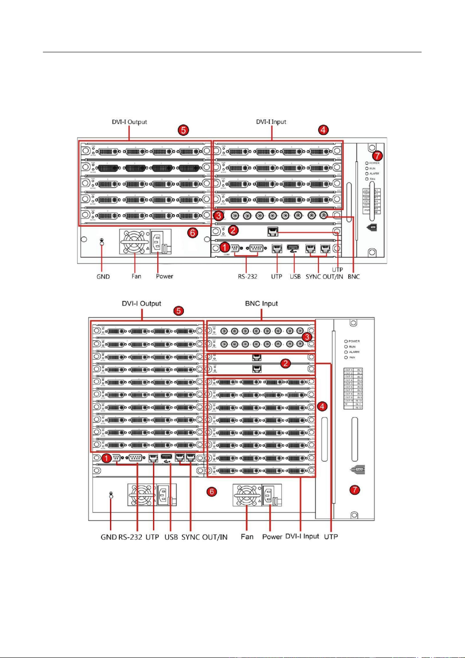
1.3.2 Rear Panel
Refer to the following gures and table for the rear panel of C10S S11/E, C10S S22/E and DS- - DS- -
DS- -C10S S41 ./E
Figure 1-4 - DS C10S-S11/E Rear Panel
Figure 1-5 - DS C10S-S22/E Rear Panel
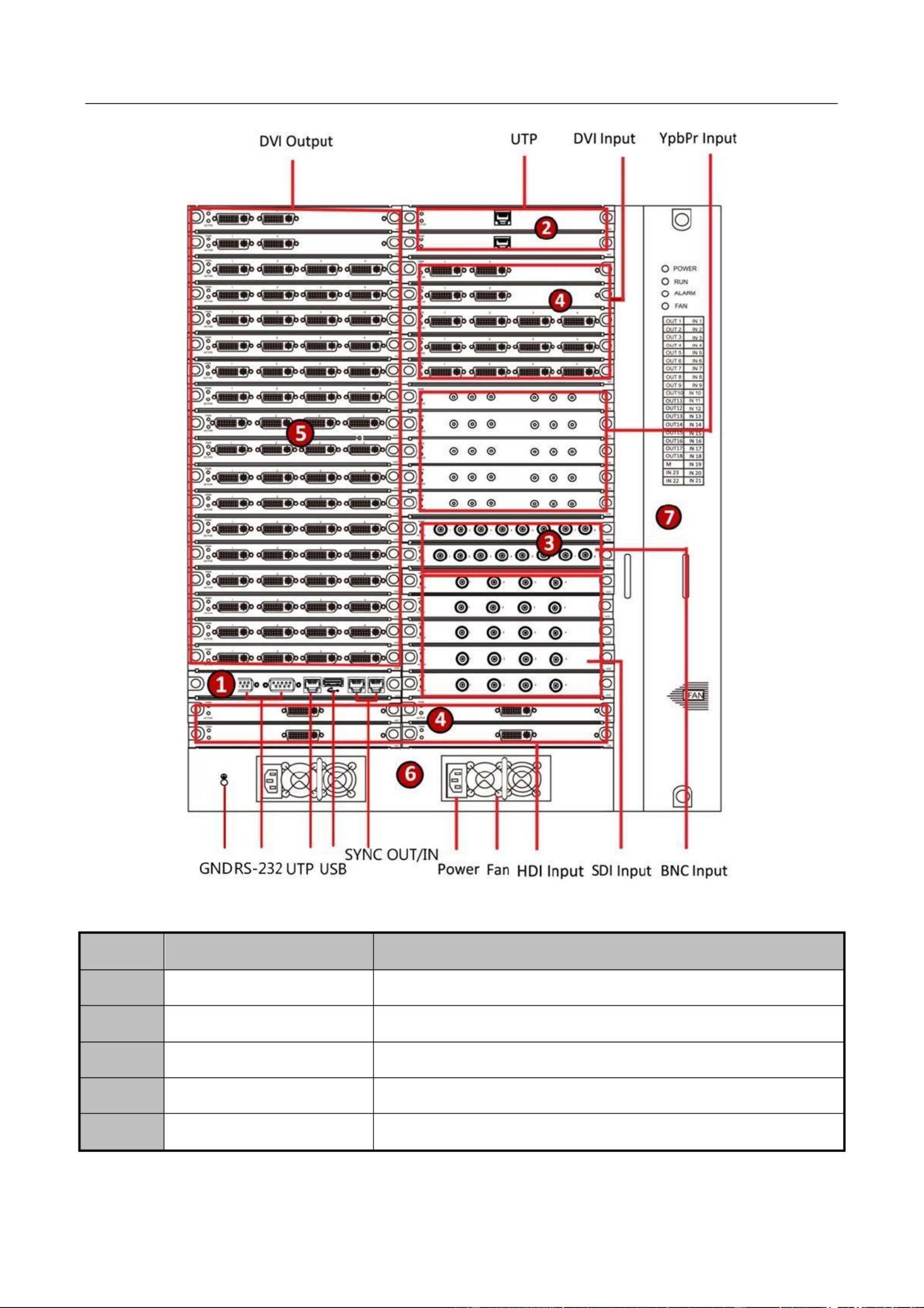
User Manual of DS-C10S-SXX/E Series Video Wall Controller
12
Figure 1-6 - DS C10S-S41/E Rear Panel
Table 1-2 - DS C10S-SXX/E Rear Panel Descripon
No.
Name
Description
1
Motherboard
Includes USB, UTP, and RS-232 interfaces.
2
Network Decoding Board
With UTP interfaces
3
BNC Input Board
With BNC input interfaces
4
DVI- Input Board I
With DVI-I input interfaces
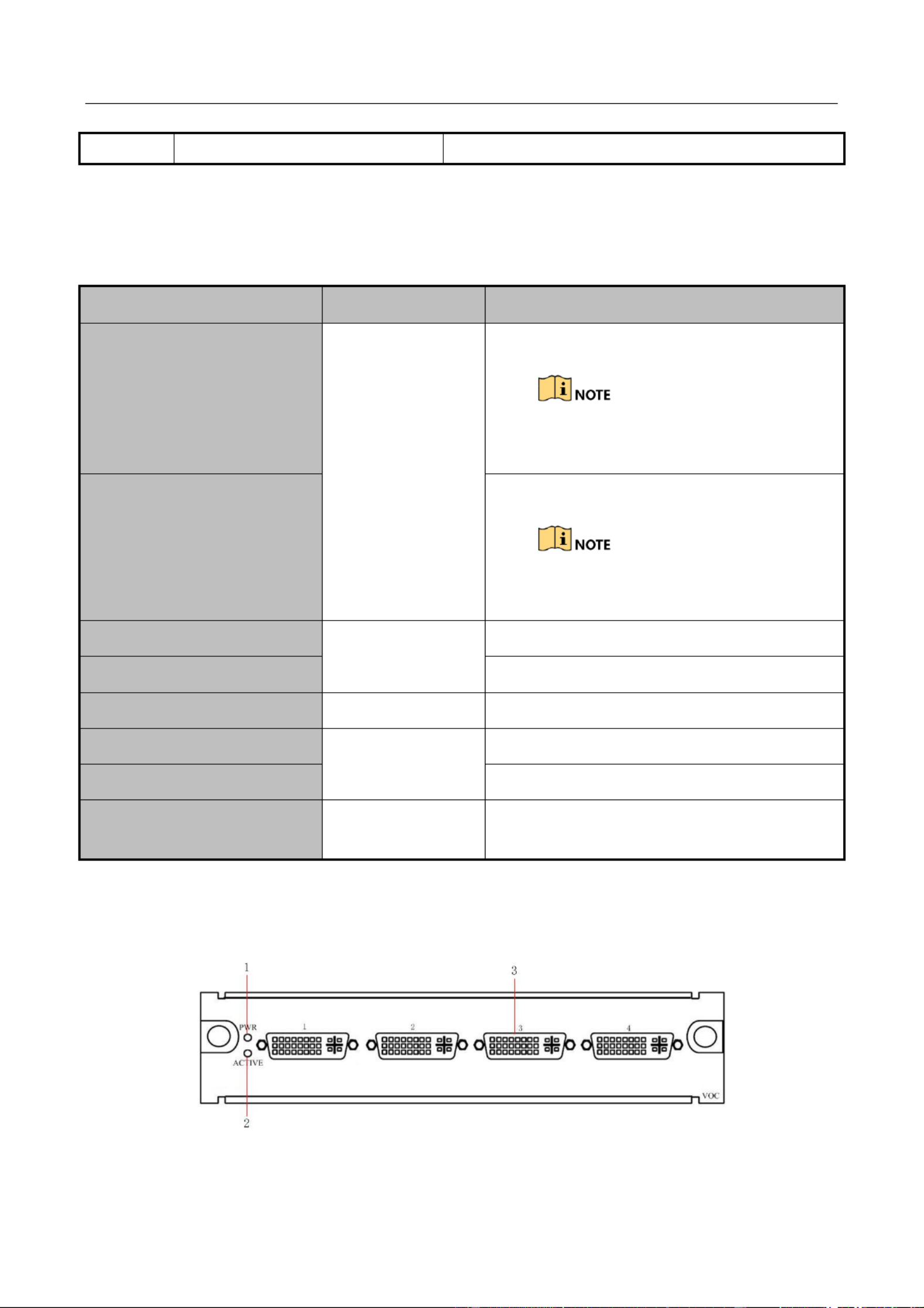
5
DVI- Output Board I
With DVI-I output interfaces

User Manual of DS-C10S-SXX/E Series Video Wall Controller
13
1.3.3 Motherboard
Refer to Table 1 3 for the model and descripon of the motherboard.-
Table 1-3 Motherboard Model
Model
Module
Description
DS-C10S-MSU
Motherboard
Motherboard of -C10S-SXX/E DS
Refer to the Figure 1 7 and Table 1 4 for the rear panel the motherboard.- - of
Figure 1-7 Motherboard Rear Panel
6
Power
Contains the physical power switch, power plug and power
supply fan.
Ensure that the device is grounded and the AC power
supply is stable and within the range of the rated voltage of
the unit. If the AC power is likely to have spikes or power
dips, use power line condioning or an uninterrupted
power supply (UPS).
7
Fan
There are four indicators on the fan board. They are the
POWER, RUN, ALARM and FAN. When the fan is working
normally, only the RUN and POWER indicators light. When
the fan is abnormal, the indicator lights. FAN
Hot swapping is forbidden because it may cause damage to
the fan.
User Manual of DS-C10S-SXX/E Series Video Wall Controller
14
Table 1-4 Motherboard Description
No.
Name
Description
1
Power Indicator
Turns green when the board is powered up.
2
Working Status Indicator
Flickers green when the board is working normally.
3
RS-232 Serial Interface 1
Debugging interface
4
RS-232 Serial Interface 2
Control interface for screen control, matrix linkage, and
keyboard
5
Network Interface
Interface for network transmission and control
6
USB Interface
Reserved interface
7
Synchronizing Signal
Output
Output interface for synchronizing signal (reserved)
8
Synchronizing Signal Input
Input interface for synchronizing signal (reserved)
1.3.4 Signal Input Module
Refer to Table 1 6 for the models and descripon of the input boards.-
Table 1-5 Input Board Model
Model
Module
Description
DS-C10S-DI/4E
DVI Input Board
With 4 DVI input interfaces
DS-C10S-DI/2E
With 2 DVI input interfaces
DS-C10S-HDI/1
DVI Dual-link
Ultra-HD Input
Board
With 1 DVI dual-link input interface
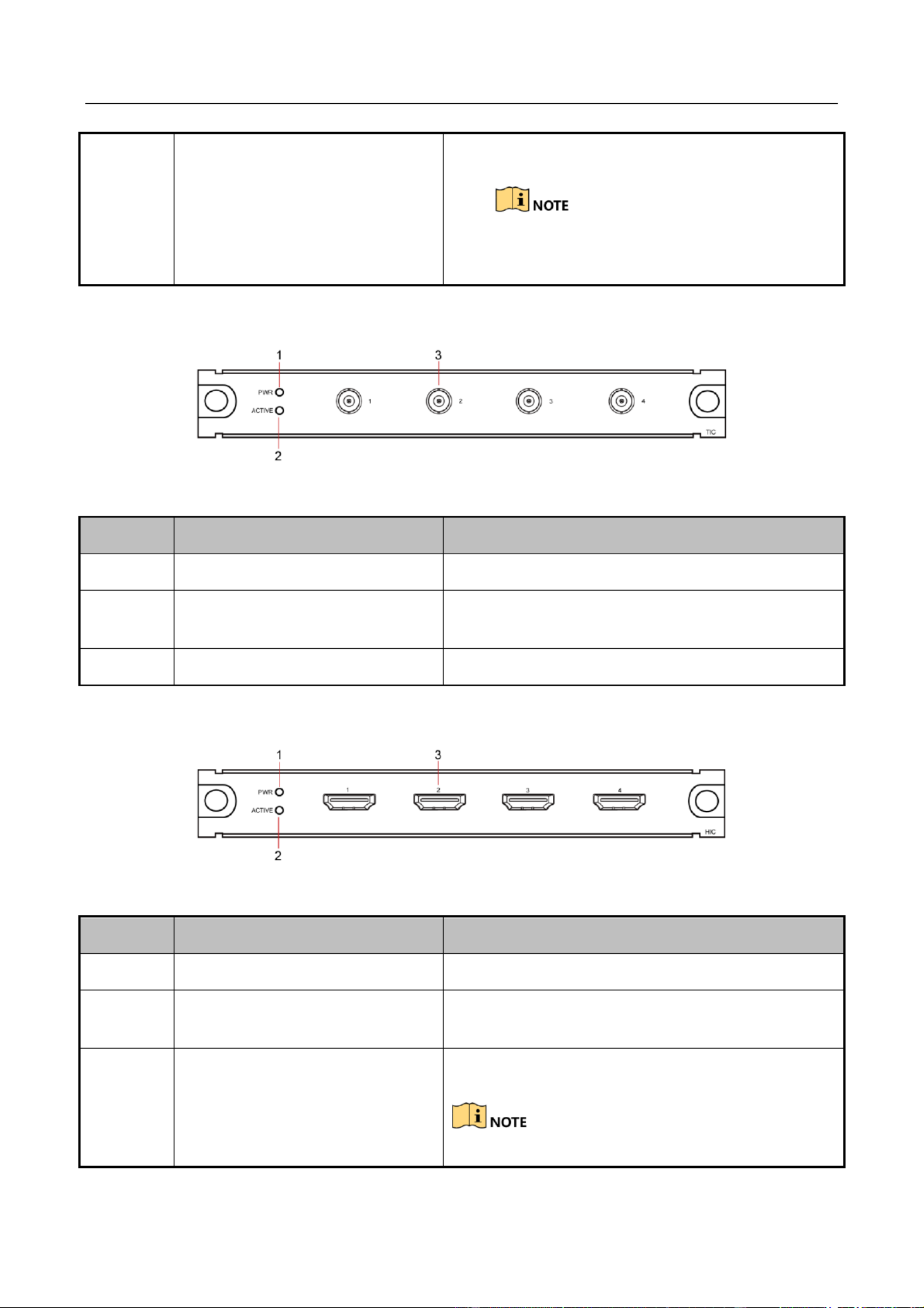
DS-C10S-HI/4
HDMI Input
Board
With 4 HDMI input interfaces
T HDMI to DVI adaptor is required for HDMI input.he
DS-C10S-HI/2
With 2 HDMI input interfaces
T HDMI to DVI adaptor is required for HDMI input.he
DS-C10S-HI/E
With 4 HDMI input interfaces
DS-C10S-VI/4E
VGA Input Board
With 4 VGA input interfaces

User Manual of DS-C10S-SXX/E Series Video Wall Controller
15
For the rear panels of the input boards, refer to the following gures and tables.
DVI Input Board ( -C10S-DI/4E DS & DS-C10S-DI/2E)
Figure 1-8 - DS C10S-DI/4E Rear Panel
The VGA to DVI adaptor is required for VGA input.
DS-C10S-VI/2E
With 2 VGA input interfaces
The VGA to DVI adaptor is required for VGA input.
DS-C10S-BI/8
BNC Input Board
With 8 BNC input interfaces
DS-C10S-SDI/4
SDI Input Board
With 4 SDI input interfaces
DS-C10S-YI/2
YPbPr Input
Board
With 2 YPbPr input interfaces
DS-C10S-HDBI/4
HDBaseT Input
Board
With 4 HDBase input interfaces
DS-C10S- SI
Network
Decoding Board
Decoding network signal with resoluon at 2- ch@5.0 MP,
4- @1080p, 8- @720p or 16- @D1 ch ch ch
DS-C10S-SI/ UH
Enhanced
Network
Decoding Board
Decoding network signal with resoluon at 2-ch@8.0 MP
(low frame rate), 2- (full frame rate), 2- .0 ch@6.0 MP ch@5
MP (full frame rate), 4- @5.0 (low frame rate), ch MP
8- @1080p, 16-ch ch@720p or 32- @D1, supporng H.265 ch
DS-C10S-DPI/4
DP (DisplayPort)
Input Board
With 4 DP input interfaces
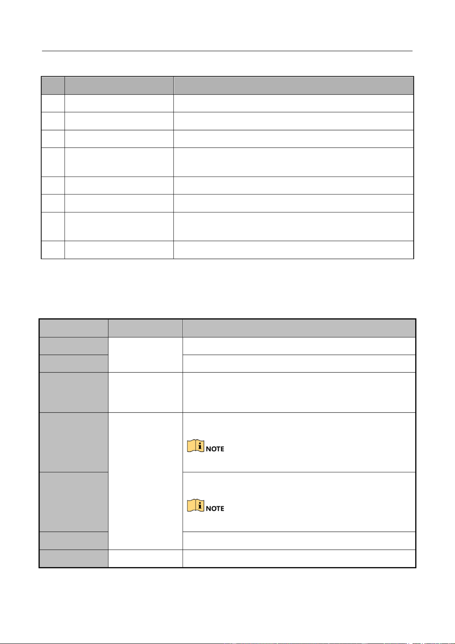
DS-C10S-TVI/4
HDTVI Input
Board
With 4 HDTVI input interfaces

User Manual of DS-C10S-SXX/E Series Video Wall Controller
16
Figure 1-9 - DS C10S-DI/2E Rear Panel
Table 1-6 DVI Input Board Description
No.
Name
Description
1
Power Indicator
Turns green when the board is powered up.
2
Working Status Indicator
Flickers green when the board is working normally.
3
DVI-I Input Interface
DVI- input interface I
The VGA to DVI adaptor is required for VGA input and
the HDMI to DVI adaptor is required for HDMI input.
DVI Dual-Link Input Board ( -C10S-HDI/1) DS
Figure 1-10 DS-C10S-HDI/1 Rear Panel
Table 1-7 DVI Dual-Link Input Board Descripon
No.
Name
Description
1
Power Indicator
Turns green when the board is powered up.
2
Working Status Indicator
Flickers green when the board is working normally.
3
DVI-I Input Interface
DVI- input interface I

User Manual of DS-C10S-SXX/E Series Video Wall Controller
17
SDI Input Board ( -C10S-SDI/4) DS
Figure 1-11 DS-C10S-SDI/4 Rear Panel
Table 1-8 SDI Input Board Descripon
BNC Input Board (DS-C10S-BI/8)
Figure 1-12 DS-C10S-BI/8 Rear Panel
Table 1-9 BNC Input Board Descripon
No.
Name
Description
1
Power Indicator
Turns green when the board is powered up.
2
Working Status Indicator
Flickers green when the board is working normally.
3
SDI Input Interface
Input interface for SDI high denion digital signal
No.
Name
Description
1
Power Indicator
Turns green when the board is powered up.
2
Working Status Indicator
Flickers green when the board is working
normally.
3
BNC Input Interface
Input interface for BNC signal

User Manual of DS-C10S-SXX/E Series Video Wall Controller
18
YPbPr Input Board ( -C10S-YI/2) DS
Figure 1-13 DS-C10S-YI/2 Rear Panel
Table 1- YPbPr Input Board Descripon 10
Network Decoding Board ( -C10S- and Enhanced Network Decoding DS SI)
Board (DS-C10S-SI/UH)
Figure 1-14 DS-C10S-SI Rear Panel
Figure 1-15 DS-C10S-SI/UH Rear Panel
Table 1-11 Network Decoding Board and Enhanced Network Decoding Board Descripon
No.
Name
Description
1
Power Indicator
Turns green when the board is powered up.
2
Working Status Indicator
Flickers green when the board is working
normally.
3
YPbPr Input Interface
Input interface for YPbPr signal
No.
Name
Description
1
Power Indicator
Turns green when the board is powered up.
2
Working Status Indicator
Flickers green when the board is working

User Manual of DS-C10S-SXX/E Series Video Wall Controller
19
DP Input Board ( -C10S-DPI/4) DS
Figure 1-16 DS-C10S-DPI/4 Rear Panel
Table 1- DP Input Board Descripon 12
HDBaseT Input Board (DS-C10S-HDBI/4)
Figure 1-17 DS-C10S-HDBI/4 Rear Panel
Table 1-13 HDBaseT Input Board Descripon
normally.
3
Network Interface
The decoding board needs to be connected to the
network independently.
No.
Name
Description
1
Power Indicator
Turns green when the board is powered up.
2
Working Status Indicator
Flickers green when the board is working
normally.
3
DP Input Interface
Input interface for DP signal
No. 1 and 3 interfaces support signal input of up
to 4096 × 2160@30 resoluon. Hz
No.
Name
Description
1
Power Indicator
Turns green when the board is powered up.
2
Working Status Indicator
Flickers green when the board is working
normally.
User Manual of DS-C10S-SXX/E Series Video Wall Controller
20
HDTVI Input Board ( -C10S-TVI/4) DS
Figure 1-18 DS-C10S-TVI/4 Rear Panel
Table 1-14 HDTVI Input Board Description
HDMI Input Board (DS-C10S-HI/E)
Figure 1-19 DS-C10S-HI/E Rear Panel
Table 1- HDMI Input Board Descripon15
3
HDBaseT Input Interface
Input interface for HDBaseT signal
No. 1 and 3 interfaces support signal input of up
to 4096 × 2160@30 resoluon. Hz
No.
Name
Description
1
Power Indicator
Turns green when the board is powered up.
2
Working Status Indicator
Flickers green when the board is working
normally.
3
HDTVI Input Interface
Input interface for HDTVI signal
No.
Name
Description
1
Power Indicator
Turns green when the board is powered up.
2
Working Status Indicator
Flickers green when the board is working
normally.
3
HDMI Input Interface
Input interface for HDMI signal
No. 1 and 3 interfaces support signal input of up to
User Manual of DS-C10S-SXX/E Series Video Wall Controller
21
1.3.5 Output Module
Refer to Table 1 16 for the models and descripon of the output boards.-
Table 1- Output Board Model 16
Model
Module
Description
DS-C10S-VO/4E
VGA Output Board
With 4 VGA output interfaces
The DVI to VGA adaptor is required for VGA
output.
DS-C10S-VO/2E
With 2 VGA output interfaces
The DVI to VGA adaptor is required for VGA
output.
DS-C10S-DO/4E
DVI Output Board
With 4 DVI output interfaces
DS-C10S-DO/2E
With 2 DVI output interfaces
DS-C10S-SDO/4
SDI Output Board
With 4 SDI output interfaces
DS-C10S-HO/4E
HDMI Output
Board
With 4 HDMI output interfaces
DS-C10S-HO/2E
With HDMI output interfaces 2
DS-C10S-HDBO/4
HDBaseT Output
Board
With 4 HDBaseT output interfaces
Refer to the following gures and tables for the rear panels of the output boards.
DVI Output Board ( -C10S-DO/4E -C10S-DO/2E) DS & DS
Figure 1- -20 DS C10S-DO/4E Rear Panel
4096 × 2160@30 resoluon.Hz

User Manual of DS-C10S-SXX/E Series Video Wall Controller
22
Figure 1-21 DS-C10S-DO/2E Rear Panel
Table 1- DVI Output Board Descripon17
SDI Output Board ( -C10S-SDO/4) DS
Figure 1-22 DS-C10S-SDO/4 Rear Panel
Table 1-18 SDI Output Board Descripon
HDMI Output Board ( -C10S-HO/4E -C10S-HO/2E) DS & DS
Figure 1-23 DS-C10S-HO/4E Rear Panel
No.
Name
Description
1
Power Indicator
Turns green when the board is powered up.
2
Working Status Indicator
Flickers green when the board is working normally.
3
DVI-I Output Interface
DVI-I output interface
The DVI to VGA adaptor is required for VGA output.
No.
Name
Description
1
Power Indicator
Turns green when the board is powered up.
2
Working Status Indicator
Flickers green when the board is working normally.
3
SDI Output Interface
Interface for SDI output

User Manual of DS-C10S-SXX/E Series Video Wall Controller
23
Figure 1-24 DS-C10S-HO/2E Rear Panel
Table 1-19 HDMI Output Board Descripon
HDBaseT Output Board ( -C10S-HDBO/4) DS
Figure 1-25 DS-C10S-HDBO/4 Rear Panel
Table 1-20 HDBaseT Output Board Descripon
No.
Name
Description
1
Power Indicator
Turns green when the board is powered up.
2
Working Status Indicator
Flickers green when the board is working normally.
3
HDMI Output Interface
HDMI output interface
No.
Name
Description
1
Power Indicator
Turns green when the board is powered up.
2
Working Status Indicator
Flickers green when the board is working normally.
3
HDBaseT Output Interface
Interface for HDBaseT output

User Manual of DS-C10S-SXX/E Series Video Wall Controller
24
Chapter 2 Accessing via iVMS-4200 Video
Wall Client Software
2.1 Software Overview
You can control and manage the C10S SXX/E video wall controller via the iVMS 4200 video wall DS- - -
client soware. It provides mulple funcons, including controlling screen, displaying signals on
the video wall playback, managing scene and plan, conguring virtual LED, etc.,
2.1.1 Working Environment
Operang System: Microso Windows 7/Windows Server 2008 (32/64 bit operating system); -
Windows Server 2003 or Windows XP (32 bit operang system).-
CPU: Intel Penum IV 3.0 GHz or models above.
Memory: 1G or above.
Displayer: 1024 × 768 or above.
The soware does not support 64 bit operang system; the above menoned 64 bit operang - -
system refers to the system which supports 32 bit applicaons as well.-
2.1.2 Performance
Up to 256 controllers can be managed.
Many controllers can be added to the soware; however, only one controller can be controlled
at a me.
One controller can be connected by 320 clients at a me.
A higher hardware conguraon is needed when viewing mulple channels or HD (High Denion)
images.
2.2 Software Installation
2.2.1 Installing the Software
Double click the setup program to start the InstallShield Wizard. Follow the steps and complete the -
installaon.

User Manual of DS-C10S-SXX/E Series Video Wall Controller
25
Figure 2-1 Install Software
2.2.2 Uninstalling the Software
Opon 1:
Double click the setup program again to enter the uninstall menu. And follow the prompt to -
uninstall the soware.
Opon 2:
Enter Windows Start Menu and select uninstall iVMS 4200. Then follow the prompt to uninstall up -
the soware.
Figure 2-2 Uninsta Softwarell
2.3 User Registration and Login
2.3.1 g Re istration
Purpose
For the inial applicaon of iVMS 4200 video wall client soware, you need to register a super -
user for login.

User Manual of DS-C10S-SXX/E Series Video Wall Controller
26
Step 1 Input the User Name, Password and Conrm Password.
Step 2 (Oponal) You can check the checkbox of to log in automacally when Auto-Login
running software next me.
Step 3 Click to save the user and password. Register
Figure 2-3 Registraon
User name and password cannot be empty or contain the following characters: / \ : * ? \ "
< > |.
The valid character of user name includes numbers (0 to 9) and leers (a to z, A to .Z)
The blank character before or aer the user name will be automacally deleted.
The valid length of password for super user ranges from 6 to 16 characters. It is highly
recommended to set a password of 8 to 16 characters. The valid length of password for
other users should be less than 16 characters.
Password cannot be copied pasted.or
2.3.2 Login
Step 1 Input the and User Name Password.
Step 2 (Oponal) Check the checkbox of to log in automacally when running Auto Login-
soware next me.
Step 3 Click to log in.Login
Figure 2-4 Login Interface
2.4 Using the Wizard for Basic Configuration
Purpose

User Manual of DS-C10S-SXX/E Series Video Wall Controller
27
Aer inial login, the setup wizard pops up automacally. It can walk you through some basic
sengs of the video wall client soware.
Figure 2-5 Start Wizard
Step 1 Click Open Wizard to enter Add Video Wall interface.
Step 2 If you don’t want to use the setup wizard at the moment, click to exit. You can also
use the Setup Wizard next me by leaving the Do Not Show Next Time unchecked.
Figure 2-6 Add Video Wall
Step 3 Draw a video wall by dragging the mouse to select the rows and columns, or inpung
values in Row and text elds. Column
Step 4 Input the video wall name in text eld.Name
Step 5 Click Next to save the sengs and enter interface.Add Device

User Manual of DS-C10S-SXX/E Series Video Wall Controller
28
Figure 2-7 Add Device
Step 6 You can a , modifydd , delete devices and show the output No. here. Three types of devices
can be added, including video wall controller, MVC (Multi-Funcon Video Center), and
decoder.
Adding Devicea
1) Click Add to pop up the adding interface.
2) Select as Adding Mode IP/Domain IP Segment or . We take adding via IP/Domain as an
example.
3) Select the Device Type Hikvision Device Third Party Device to be or -.
4) Input Nickname, Address, Port User Name Password, , and in the text elds.
5) Click Add to add the device(s).
Figure 2-8 Add a Device
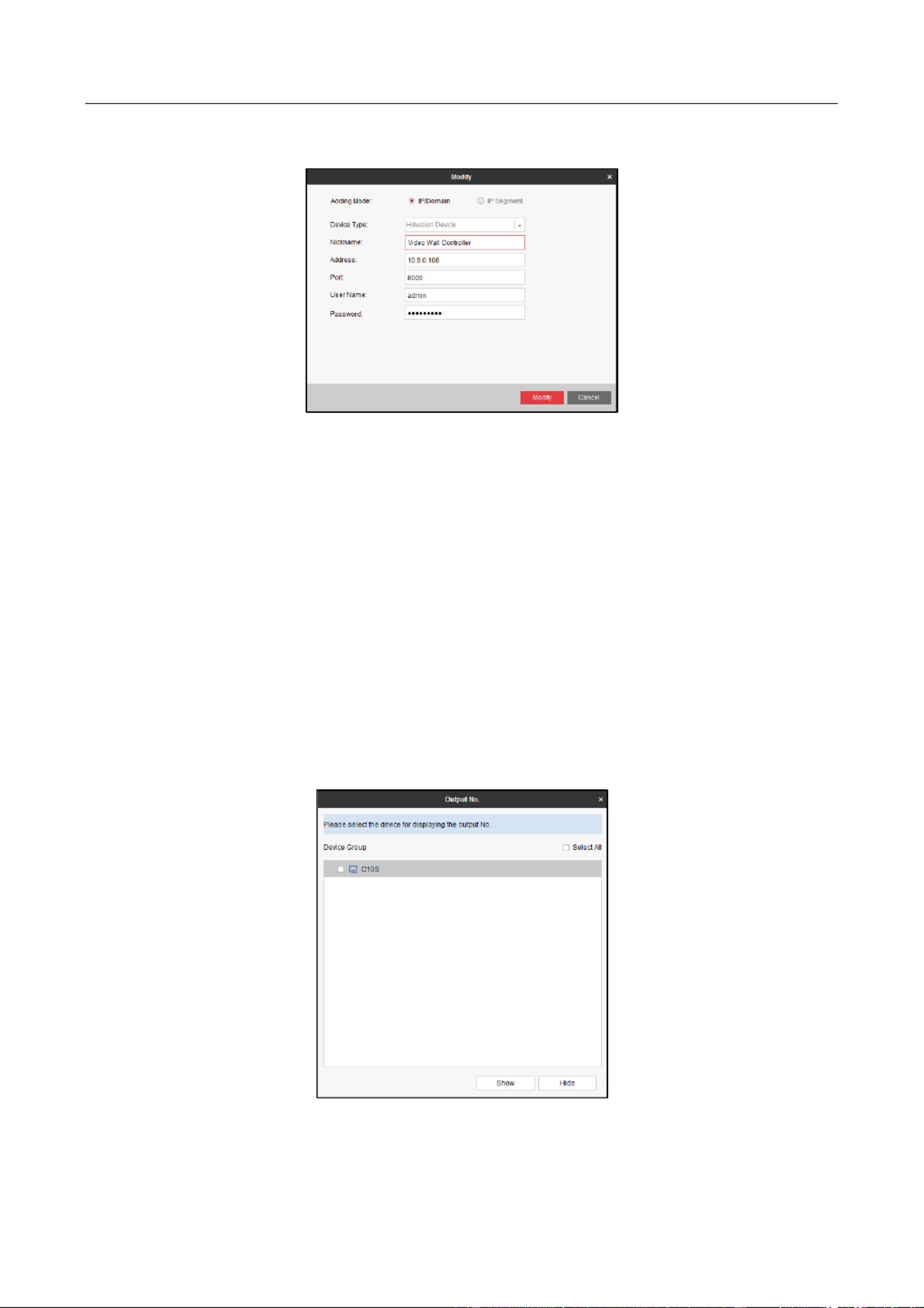
Modifying the Added Device
User Manual of DS-C10S-SXX/E Series Video Wall Controller
29
1) Select the added device and click to enter the interface.Modify Modify
Figure 2-9 Modify the Added Device
2) Edit the and to modify the parameters. Nickname, Address, Port, User Name, Password
3) Click to save the setngs.Modify
Deleng a Device
1) Select an added device.
2) Click Delete to delete it.
Showing Output No.
1) Click Output No.
2) Select the device(s) you need to display the output No.
3) Click to enable the funcon. Thus the output No. of the selected device(s) will be Show
shown on the video wall.
Figure 2-10 Show Output No.
User Manual of DS-C10S-SXX/E Series Video Wall Controller
30
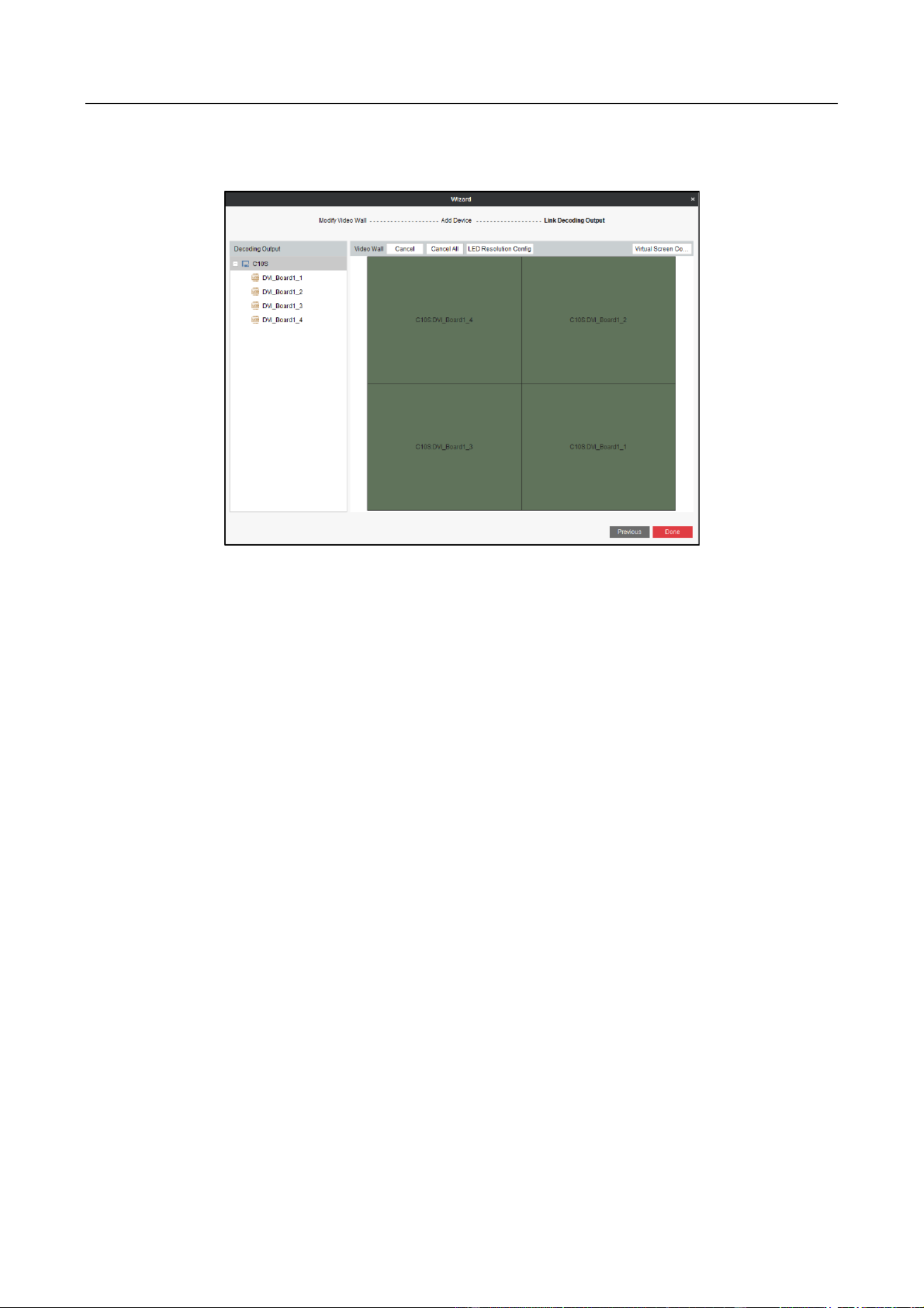
Step 7 Aer the devices are congured, click Next Link Decoding Output to enter sengs
interface.
Figure 2-11 Link Decoding Output
Step 8 You can adjust the output window of the added video wall controller, add or delete virtual
screen for the selected output window, and configure the LED output resoluon.
Adjusng the Output Window
1) Click Cancel All to clear the default sengs. Or select a window and click to clear Cancel
the linkage between the output and the window.
2) Drag a decoding output in the Decoding Output list to a window to link the output to the
window.
3) Repeat the above steps to configure other outputs.
A ing Virtual Screen dd
1) Click Virtual Screen Cong to expand the Virtual Screen Conguraon menu.

User Manual of DS-C10S-SXX/E Series Video Wall Controller
31
Figure 2-12 Congure Virtual Screen
2) Select the output area you want to add virtual screen.
3) Click Add Virtual Screen to enter the interface.
4) Select a Virtual Screen Mode and input the parameters.
5) Click OK to save the sengs.
Deleng Virtual Screen
1) Drag the mouse to select the congured virtual screen area.
2) Click Delete Virtual Screen to delete it.
Conguring LED Resoluon
1) Click to return to the Link Decoding Output interface.Back
2) Select the LED area and click LED Resoluon Cong to congure the LED resoluon.
3) Input the LED Resoluon and click OK to save the sengs.
Step 9 Click to save the setngs.Done
2.5 Graphical User Interface Introduction
Refer to Figure 2 and Table 2 1 for the introducon of the graphical user interface (GUI) of -13 -
iVMS 4200 Video Wall Client Soware.-

User Manual of DS-C10S-SXX/E Series Video Wall Controller
33
Management, and System Conguraon interface.
4
Tool
Enter Log Search, Video Wall Linkage, and Device Arming Control
interface.
5
Help
Open video wall wizard, open user manual, view soware version,
and switch language.

User Manual of DS-C10S-SXX/E Series Video Wall Controller
34
Chapter 3 Configuring Controller via the
Software
3.1 Video Wall Introduction
Click Video Wall in the Quick Launch Bar to enter Video Wall interface. For detailed conguraon,
you can refer to Chapter 4 Managing Video Wall.
Figure 3-1 Video Wall Interface
Refer to Table 3 1 for the descripon of video wall.-
Table 3-1 Video Wall Description
Region
Name
Description
1
Menu List
Manage Local Signal Source, Network Signal
Source, Scene, Plan and PTZ.
2
Window Management
Area
Open/close windows and move window s.
3
Window Management
Toolbar
Start/stop live view of all the roaming windows,
start/stop decoding all signal sources and
cameras, close/open windows, start/stop VCA
decoding for all signal sources and cameras,
open window via coordinate, enable/disable
video wall mirror, and refresh live view screens.

User Manual of DS-C10S-SXX/E Series Video Wall Controller
35
Refer to Figure 3 2 and Table 3 2 for the descripon of window management toolbar.- -
Figure 3-2 Window Management Toolbar
Table 3-2 Window Management Toolbar Descripon
4
Advanced Sengs
Area
Sengs area for advanced parameters.
5
Advanced Sengs
Menu
Congure Window, Virtual LED, Logo and
Background Picture.
Icon
Name
Description
/
Start/Stop Live
View
Start/Stop live view of all the roaming windows.
/
Start/Stop All
Decoding
Start/Stop decoding all signal sources and
cameras.
Close All
Windows
Close all the windows displayed on the video
wall.
Start All VCA
Decoding
Start VCA decoding for all live view signals. Once
it is started, the VCA informaon can be viewed
in live view.
Stop All VCA
Decoding
Stop VCA decoding for all live view signals.
Open Window
Draw a window according to your need. The size
and posion of the window are adjustable.
Open Window via
Coordinate
Open a window by inpung X-coordinate, Y-
coordinate width and height. ,
For the detail operaons, refer to Chapter 5.2.4
Opening the Window via Coordinate.
/
Enable/Disable
Video Wall Mirror
Enable/Disable video wall mirror.
For the detail operaons, refer to Chapter 4.3.1
Mirroring Video Wall.
Refresh
Refresh the video wall status.
User Manual of DS-C10S-SXX/E Series Video Wall Controller
36
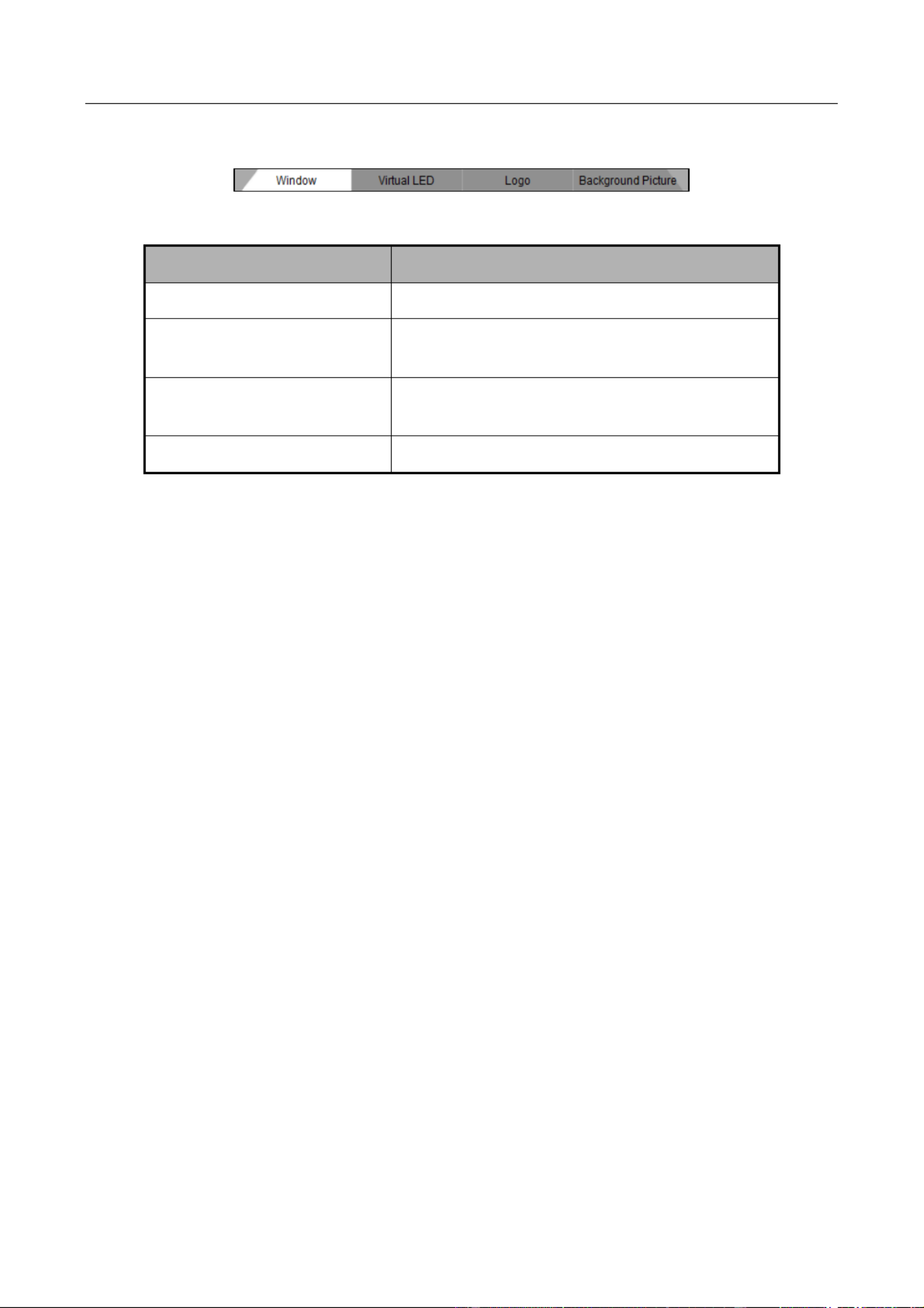
Refer to Figure 3 3 and Table 3 3 for the descripon of advanced setngs menu.- -
Figure 3-3 Advanced Sengs Menu
Table 3-3 Advanced Sengs Menu Descripon
Name
Description
Window
Advanced sengs for window s.
Virtual LED
Enable/disable virtual LED and edit virtual LED
cont ent.
Logo
Reserved funcon. Not supported by video wall
controller.
Background Picture
Upload and enable/disable background picture.
3.2 Managing Video Wall Controller
3.2.1 Activating the Video Wall Controller
Purpose
You are required to acvate the video wall controller rst by seng a strong password before
using.
Before you start
Ensure your computer is in the same network segment with the controller.
Step 1 Select in the Quick Launch Bar to enter Device Management Device Management
interface.
Step 2 Select an inacve device and click Acvate to enter Acvaon interface.

User Manual of DS-C10S-SXX/E Series Video Wall Controller
37
Figure 3-1 Device Management
Step 3 Input the password and conrm .it
Figure 3-2 Acvate the Video Wall Controller
STRONG PASSWORD RECOMMENDED–We highly recommend you create a strong password of
your own choosing (Using a minimum of 8 characters, including at least three of the following
categories: upper case letters, lower case leers, numbers, and special characters.) in order to
increase the security of your product. And we recommend you reset your password regularly,
especially in the high security system, reseng the password monthly or weekly can better protect
your product.
Step 4 Click OK to save the password and acvate the controller.
3.2.2 Adding the Video Wall Controller
Step 1 Select the acvated controller and click Modify Nenfo to set the IP address of the
controller.

User Manual of DS-C10S-SXX/E Series Video Wall Controller
38
Figure 3-3 Device Management
Step 2 Input the IP Address Gateway Password, and , and click to save the sengs.OK
Figure 3-4 Set Network Parameters
Step 3 Click the Add to Client button and input the , and Nickname, Address User Name
Password for the controller.
Figure 3-5 Add the Video Wall Controller
STRONG PASSWORD RECOMMENDED–We highly recommend you create a strong password of
your own choosing (Using a minimum of 8 characters, including at least three of the following
categories: upper case letters, lower case leers, numbers, and special characters.) in order to
increase the security of your product. And we recommend you reset your password regularly,
especially in the high security system, reseng the password monthly or weekly can better protect
your product.
User Manual of DS-C10S-SXX/E Series Video Wall Controller
39
Step 4 Click Add to add it.
3.3 Configuring Remote Settings
Purpose
In the remote conguraon interface, the parameters of the added controller, including the system,
network, etc., can be set.
Select an added controller and click Remote Conguraon to enter Remote Conguraon
interface.
Figure 3-6 Remote Conguration Interface
Refer to Table 3 4 for the descripon of remote conguraon.-
Table 3-4 Description of Remote Configuration
Parameters
Description
System
View device informaon and status, congure general
parameters and users manage device, set me, search and ,
backup logs.
Network
Congure general network parameters.
Event
Congure excepon linkage method.
Video
Display
Upload background picture, congure video parameters of input
signal, adjust picture posion congure background color, ,
congure the input signal resoluon and congure OSD.
Others
Bind the screen server, congure the decoding device
parameters, congure the matrix linkage parameters, collage
the signal source and congure the motherboard serial port

User Manual of DS-C10S-SXX/E Series Video Wall Controller
40
3.3.1 Configuring System Settings
You can congure the parameters listed in Table 3 5 for the system sengs. Here we take the -
working status conguraon as an example.
Table 3-5 Descripon of System
Parameters
Description
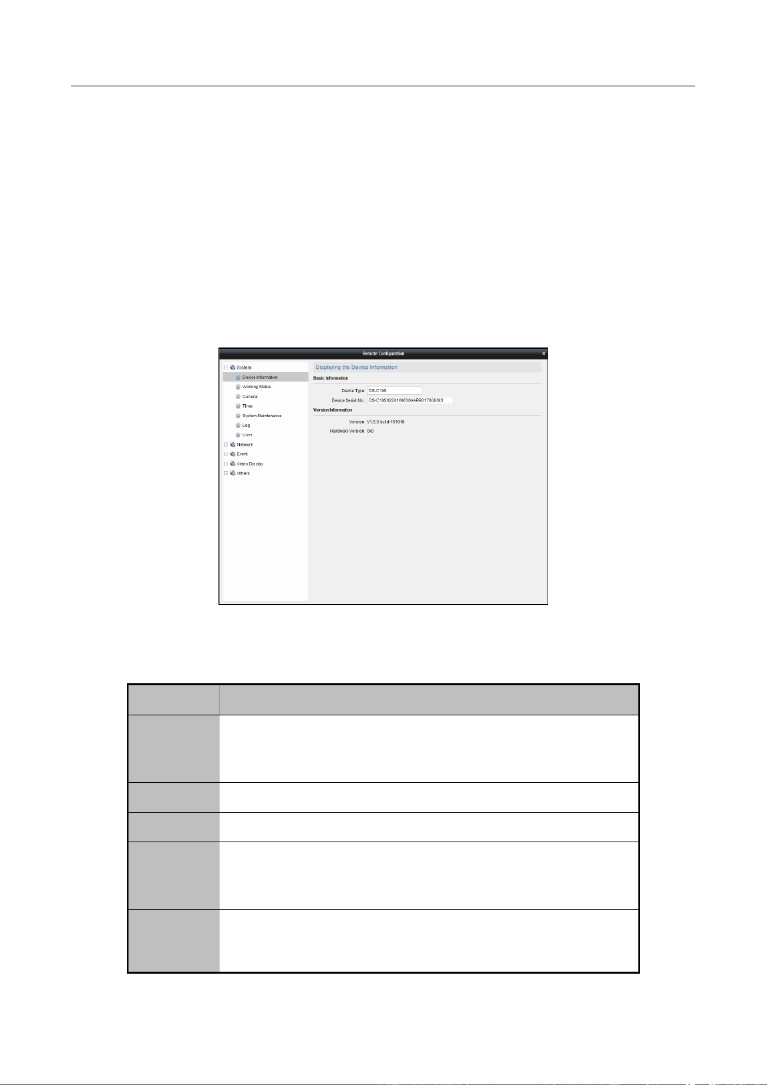
Device
Informaon
View basic informaon and version.
Working Status
Display the status of the controller sub-boards, and fans. ,
General
Congure device name.
Time
Congure me zone, NTP and DST parameters.
System
Maintenance
System management and remote upgrade.
Log
Search and back device logs. up
User
Add operators and specify permissions.
Up to users can be added. The admin can add, modify and 32
delete other operators Operators can only modify .
parameters of their own.
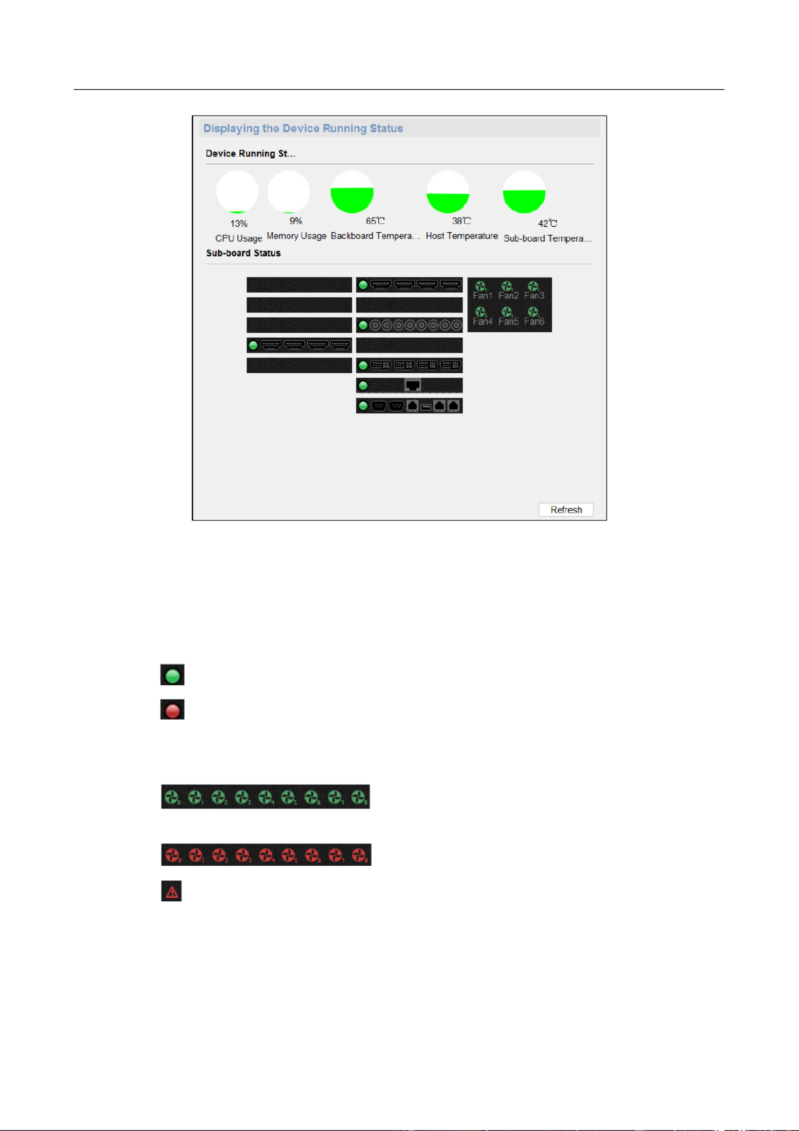
Viewing Working Status
Purpose
You can view the device running status such as CPU usage, memory usage, backboard temperature,
host temperature, sub board temperature, sub board status, and fan status.- -
Step 1 Go to System > Working Status.
parameters.
User Manual of DS-C10S-SXX/E Series Video Wall Controller
41
Figure 3-7 Working Status
Step 2 View the device running status.
You can view the CPU usage, memory usage, backboard temperature, host temperature,
and sub-board temperature.
Step 3 View the s board status.ub-
: It means the status is normal.
: It means the status is abnormal. Move the cursor to the red indicator and you
can view the excepon informaon.
Step 4 View the fan status.
: It means the fan is working normally. The number
on the lower right corner of the icon shows the rotang speed of the fan.
: It means the rotang speed of the fan is abnormal.
: It means there is communicaon excepon of the fan.
Step 5 (Oponal) Click Refresh to refresh the status.
3.3.2 Configuring Network Settings
Step 1 Click Network tab.

User Manual of DS-C10S-SXX/E Series Video Wall Controller
42
Figure 3-8 Network Conguraon Interface
Step 2 Select NIC Type from the dropdown list.
Step 3 Input IPv4 Address Subnet Mask, and Default Gateway.
Step 4 Click Save to save the setngs.
3.3.3 Configuring Event Settings
Step 1 Click Event tab.
Figure 3-9 Event Conguraon Interface
Step 2 Enable Link Device Alarm Audio ed by checking the corresponding checkbox.
Step 3 Click Save to save the setngs.
3.3.4 Configuring Video Display Settings
Step 1 Click Video Display tab.
Figure 3-10 Video Display Conguration Interface

User Manual of DS-C10S-SXX/E Series Video Wall Controller
43
Step 2 Click Background Picture Video Parameters, , Picture Adjustment, Background Color,
Signal Resoluon, or OSD configure corresponding parameters. For details, refer to to
Table 3 6 below.-
Table 3-6 Description of Video Display Settings
Configuring Signal Resolution
Purpose
You can configure the resolution of the input signals.
Step 1 Click Signal Resoluon to enter the Signal Resolution Configuration interface.
Figure 3-11 Configure Input Signal Resolution
Step 2 Select the input signal from the dropdown list.Signal Source Name
Step 3 Set the Refreshing Frequency.
Step 4 Input the resolution in the Resolution text fields.
Parameters
Description
Background
Picture
Upload local picture as the background of output screen.
Video
Parameters
Adjust the video parameters of input signal.
Picture
Adjustment
Adjust the position of input signal.
Background
Color
Set the background color of output.
Signal
Resolution
Set the signal resolution and refreshing frequency. For
detailed steps, refer to Conguring Signal Resoluon.
OSD
Set the on-screen-display parameters. For detailed steps,
refer to . Conguring OSD

User Manual of DS-C10S-SXX/E Series Video Wall Controller
44
Step 5 Check the checkbox of to enable the custom signal resolution.Enable
Step 6 If you want to copy the same configuration to other input signals, click to expand the
signal input list and check the corresponding checkbox(es) to select the input signal(s).
Step 7 Click Save to save the settings.
The resolution cannot exceed the maximum resolution supported by the signal source. If
the resolution exceeds 1920*1200, the maximum refreshing frequency can only be set to
30.
Only the HDMI and DP input interfaces are supported. If interfaces of other types are
connected, it will remind that the transmitted data error.
For the HDMI 4K interface, the max. resolution is 4096*2160, and the min. resolution is
640*480.
Step 8 Change the display resolution of your computer. Refer to Chapter 4.8 Setting the Custom
Resolution on the Computer for reference.
Configuring OSD
Purpose
You can configure the OSD (On Screen Display) of the input signal.
The OSD configuration is supported for the HDMI and DP signal inputs of DS C10S series - -SXX/E
video wall controller.
Step 1 Click to enter the OSD Configuration interface.OSD
Figure 3-12 Configure OSD
Step 2 Select the input signal from the dropdown list.Signal Name
Step 3 The Font Size cannot be configured and the default size is 64.

User Manual of DS-C10S-SXX/E Series Video Wall Controller
45
Step 4 Click to select the Font Color. Or you can set the custom color. Click to save the OK
font color.
Step 5 Click the field after the Content checkbox to edit the information you want to show on the
OSD. Up to 24 English characters can be edited.
Step 6 Check the checkbox of Content show the edited information on the OSD or uncheck it to
to hide it.
Step 7 Click to adjust the X Coordinate Y Coordinate- and - or you can input the numbers in the
text fields. Or you can drag the textbox on the left window to adjust its position.
Step 8 Click OK to save the settings.
3.3.5 Configuring Other Settings
Step 1 Click Others tab.
Figure 3-13 Others Configuration Interface
Step 2 Select the tab such as Screen Controller Server Bind Decoding Board Matrix Linkage, , ,
Signal Source Collage Motherboard Serial Port, , or Distributed Source Management. For
details, please refer to Table 3 7 Description of Other Settings- .
Table 3-7 Description of Other Settings
Parameters
Description
Screen
Controller
Server Bind
Bind the input signal with the screen controller server .
Only when the screen server is installed and enabled on the
computer with configured signal source, can the screen controller

User Manual of DS-C10S-SXX/E Series Video Wall Controller
46
Linking Matrix
Purpose
You can add, modify and delete the linked matrix in matrix linkage configuration.
server be bound in the remote configuration.
After the screen controller server is bound, you can control the
computer installed with by right clicking the remote interaction it -
of the video wall window via the client, such as opening the
document, PowerPoint and video.
Decoding
Board
Configure the general network parameters of decoding board and
view decoding board status.
Decording board needs be independently connected to network.
And it does not decode the stream with frame rate below 1 fps.
Matrix
Linkage
Add, edit and delete link matrix. The channels of added matrix ed
will be listed in signal sources of video wall interface and you can
display it on video wall. For detailed operations, refer to Linking
Matrix.
Before displaying the matrix signal sources, you need to do
following operations.
Connect the COM 2 of motherboard to the COM port of matrix.
Configure the board function of motherboard as matrix control.
Signal Source
Collage
Collage several signal sources into one. For detailed operations,
refer to . Collaging Signal Sources
Motherboard
Serial Port
Configure the parameters of motherboard serial port.
The Board Function can to be set as Matrix Control, Screen Control
or Keyboard Control according to the serial port usage.
Distributed
Source
Management
Add, modify and delete the distributed network sources For .
detailed operations, refer to Managing Distributed Sources.

User Manual of DS-C10S-SXX/E Series Video Wall Controller
47
Step 1 Click Matrix Linkage tab to enter the Matrix Linkage Configuration interface.
Figure 3-14 Configure Matrix Linkage
Step 2 Click Add to add the matrix.
Figure 3-15 A Matrixdd
Step 3 Input the (custom) and Matrix Name, Matrix ID , Matrix Input Number Matrix Output
Number Matrix Channel Type Matrix Protocol Baud Rate Data Bit Stop Bit. Select the , , , ,
and Parity.
Matrix protocol of ZT1.0 ZT2.0 Extron, Creator and HIK_CVBS_96P are supported., ,
Up to 4 matrixes can be connected. If the matrix protocol is HIK_CVBS_96P, up to 512 X 512
input channels of each matrix are supported. If the matrix protocol is others, up to X 512
128 input channels of each matrix are supported.
Step 4 Click Next to link the input channel with the matrix output channel.
1) Click to select the input channel to link with the matrix output channel.
2) Click Save to save the settings.
Figure 3-16 Link Input Channel

User Manual of DS-C10S-SXX/E Series Video Wall Controller
48
Step 5 On the Device Management interface, click to refresh the controller.
Step 6 (Optional) You can click or on the Modify Delete Matrix Linkage interface to modify or
delete the linked matrix.
After the matrix configuration, enter the Video Wall interface. The input channels of the linked
matrix will be listed in the Local Signal Source list. You can drag one input channel of the linked
matrix to the video wall as shown below.
Figure 3-17 Display Matrix Input Channel to the Video Wall
Collaging Signal Sources
Purpose
You can collage several signal sources into one.
Step 1 Click Signal Source Collage to enter Signal Source Collage interface.
Figure 3-18 Collage Signal Source
Step 2 Click Add to add collaged signal source.

User Manual of DS-C10S-SXX/E Series Video Wall Controller
49
Figure 3-19 Add Collaged Signal Source
Step 3 Input the Collaged Signal Source Name Row, and input the and in the Column
corresponding text fields.
Step 4 Drag signal sources need to be collaged into the windows. ed
Only the local signal sources can be collaged.
Ensure each window links one signal source.
Step 5 Click Save to save the settings.
Step 6 (Optional) You can also select a window and click to cancel collaging the selected Cancel
signal source or click to cancel all the collaged signal sources.Cancel All
Step 7 Return to the Signal Source Collage interface. Select the added collaged signal source and
the input signal sources included in the collaged signal source will be displayed.
Figure 3-20 Collaged Signal Source
Step 8 (Optional) Select the added collaged signal source and click to modify it.Modify
Step 9 (Optional) Select the added collaged signal source and click to delete it.Delete

User Manual of DS-C10S-SXX/E Series Video Wall Controller
50
Step 10 Enter the Video Wall interface and the collaged signal source will be listed in the Local
Signal Source list. Drag it to display on the video wall.
Figure 3-21 Display Collaged Signal Source on the Video Wall
When dragging the collaged signal source to the video wall, it will be displayed together in a
single window.
When roaming or zooming in or zooming out the collaged signal source window, each signal
source in it will be roamed or zoomed in or zoomed out.
Managing Distributed Sources
Purpose
You can manage the distributed network sources to raise the signal source capacity and
transmission distance.
Step 1 Click Distributed Source Management tab to enter the Distributed Source Management
interface.
Figure 3-22 Manage Distributed Sources
Step 2 Click Add to enter the Distributed Network Source Configuration interface.
Termékspecifikációk
| Márka: | Hikvision |
| Kategória: | távirányító |
| Modell: | DS-C10S-HI4T-HD |
Szüksége van segítségre?
Ha segítségre van szüksége Hikvision DS-C10S-HI4T-HD, tegyen fel kérdést alább, és más felhasználók válaszolnak Önnek
Útmutatók távirányító Hikvision

4 Szeptember 2024
28 Augusztus 2024
26 Augusztus 2024
21 Augusztus 2024
21 Augusztus 2024
21 Augusztus 2024
21 Augusztus 2024
18 Augusztus 2024
Útmutatók távirányító
- távirányító Samsung
- távirányító PeakTech
- távirányító Sony
- távirányító Yamaha
- távirányító Nedis
- távirányító Milwaukee
- távirányító LG
- távirányító Grundig
- távirányító Parkside
- távirányító Marantz
- távirányító Philips
- távirányító Pioneer
- távirányító SilverCrest
- távirányító Garmin
- távirányító Panasonic
- távirányító Canon
- távirányító JVC
- távirányító AEG
- távirányító Harman Kardon
- távirányító Toshiba
- távirányító Neumann
- távirányító Apple
- távirányító HQ
- távirányító Medion
- távirányító Motorola
- távirányító Geemarc
- távirányító Vimar
- távirányító LogiLink
- távirányító Miele
- távirányító Technics
- távirányító Hunter
- távirányító Futaba
- távirányító Insignia
- távirányító EZVIZ
- távirányító Crestron
- távirányító ORNO
- távirányító Strong
- távirányító Tripp Lite
- távirányító Omega
- távirányító Thomson
- távirányító Hegel
- távirányító Reely
- távirányító Technaxx
- távirányító Ardes
- távirányító Interphone
- távirányító Kenwood
- távirányító Vivanco
- távirányító Hama
- távirányító Mitsubishi
- távirányító Bose
- távirányító Iogear
- távirányító BeamZ
- távirányító DSC
- távirányító Continental Edison
- távirányító Telefunken
- távirányító Doro
- távirányító Nikon
- távirányító Alpine
- távirányító Logitech
- távirányító Pro-Ject
- távirányító Smart
- távirányító TOA
- távirányító Parrot
- távirányító SVS
- távirányító American DJ
- távirányító Scosche
- távirányító Naim
- távirányító Fibaro
- távirányító Devolo
- távirányító Memphis Audio
- távirányító DJI
- távirányító Autel
- távirányító Audio-Technica
- távirányító Amazon
- távirányító Funai
- távirányító Antec
- távirányító Cisco
- távirányító Energy Sistem
- távirányító JL Audio
- távirányító Nexa
- távirányító Control4
- távirányító Loewe
- távirányító Chamberlain
- távirányító Ei Electronics
- távirányító Fantini Cosmi
- távirányító Chauvet
- távirányító Grohe
- távirányító REV
- távirányító Intertechno
- távirányító Spektrum
- távirányító BENNING
- távirányító Honeywell
- távirányító Velleman
- távirányító Morel
- távirányító Russound
- távirányító FireAngel
- távirányító Clarion
- távirányító Amewi
- távirányító EQ-3
- távirányító Metra
- távirányító Monacor
- távirányító One For All
- távirányító NAD
- távirányító Viper
- távirányító Conrad
- távirányító Uni-T
- távirányító Delta
- távirányító TomTom
- távirányító Busch-Jaeger
- távirányító Olympia
- távirányító Delta Dore
- távirányító Abus
- távirányító Infinity
- távirányító Bang & Olufsen
- távirányító Trust
- távirányító Iiyama
- távirányító Chief
- távirányító Konig
- távirányító Marmitek
- távirányító Jensen
- távirányító Meliconi
- távirányító Steinel
- távirányító DataVideo
- távirányító Watson
- távirányító Lindy
- távirányító Danfoss
- távirányító Gaggenau
- távirányító Technika
- távirányító Arctic Cooling
- távirányító Rotel
- távirányító NEC
- távirányító AudioControl
- távirányító Cotech
- távirányító Siig
- távirányító Rockford Fosgate
- távirányító Dual
- távirányító Projecta
- távirányító Gefen
- távirányító Kathrein
- távirányító Homematic IP
- távirányító RCA
- távirányító Provision-ISR
- távirányító Axis
- távirányító Optex
- távirányító Magnus
- távirányító Kicker
- távirányító LRP
- távirányító Genius
- távirányító Valueline
- távirányító PowerBass
- távirányító Adj
- távirányító Wacom
- távirányító MB Quart
- távirányító H-Tronic
- távirányító Tascam
- távirányító Packard Bell
- távirányító Sitecom
- távirányító Schwaiger
- távirányító Multibrackets
- távirányító Neewer
- távirányító Dot Line
- távirányító Match
- távirányító RADEMACHER
- távirányító Majestic
- távirányító REVO
- távirányító CSL
- távirányító Artsound
- távirányító Vogel's
- távirányító Profoto
- távirányító Manfrotto
- távirányító Ansmann
- távirányító Reflecta
- távirányító Ziggo
- távirányító Brennenstuhl
- távirányító Absima
- távirányító Yale
- távirányító Tevion
- távirányító Eminent
- távirányító SilverStone
- távirányító Targus
- távirányító Exibel
- távirányító Hähnel
- távirányító KlikaanKlikuit
- távirányító Vision
- távirányító Sonos
- távirányító Kensington
- távirányító Maginon
- távirányító Magnum
- távirányító Steren
- távirányító Perel
- távirányító KPN
- távirányító Bigben Interactive
- távirányító ESYLUX
- távirányító Malmbergs
- távirányító AV:link
- távirányító Vello
- távirányító Audiovox
- távirányító Unitron
- távirányító Hager
- távirányító Asustor
- távirányító Tado
- távirányító Clas Ohlson
- távirányító Nemef
- távirányító Hema
- távirányító Sweex
- távirányító Vizio
- távirányító Vakoss
- távirányító EVE
- távirányító Xit
- távirányító Metronic
- távirányító Waeco
- távirányító Natec
- távirányító T'nB
- távirányító Hannspree
- távirányító Xavax
- távirányító Provision
- távirányító Schaudt
- távirányító Niko
- távirányító Humax
- távirányító Vaddio
- távirányító Jung
- távirányító Zephir
- távirányító Lifetec
- távirányító Apart
- távirányító Electia
- távirányító Genaray
- távirányító Jolly
- távirányító ELV
- távirányító Msonic
- távirányító Nanlite
- távirányító Verizon
- távirányító Tihao
- távirányító Revox
- távirányító Zapman
- távirányító OEM
- távirányító Emtec
- távirányító Ranex
- távirányító Jasco
- távirányító CME
- távirányító Ruwido
- távirányító Engel Axil
- távirányító Fusion
- távirányító Bazooka
- távirányító Wentronic
- távirányító Walkera
- távirányító EQ3
- távirányító Satechi
- távirányító Edision
- távirányító Neets
- távirányító ETiger
- távirányító VDO Dayton
- távirányító Aeon Labs
- távirányító Aputure
- távirányító Entone
- távirányító Fortin
- távirányító Samlex
- távirányító Zalman
- távirányító Simplify
- távirányító Ferguson
- távirányító Wet Sounds
- távirányító Televés
- távirányító Swiss Sense
- távirányító Extron
- távirányító ProMaster
- távirányító Ebode
- távirányító RadioShack
- távirányító Exxter
- távirányító Skymaster
- távirányító Hartig Helling
- távirányító Multibox
- távirányító Online
- távirányító Libec
- távirányító Furman
- távirányító AT-T
- távirányító Logic3
- távirányító Medion MD6461
- távirányító TCM
- távirányító Pixel
- távirányító Antelope Audio
- távirányító PDP
- távirányító Ecler
- távirányító Q-Sonic
- távirányító Elite Screens
- távirányító Roswell
- távirányító SpeakerCraft
- távirányító Heitech
- távirányító Sunwave
- távirányító Tevion (Medion)
- távirányító Syrp
- távirányító Bravo
- távirányító Maximex
- távirányító Pentatech
- távirányító Glashart Media
- távirányító Bang Olufsen
- távirányító TV Vlaanderen
- távirányító Innr
- távirányító Universal Electronics
- távirányító TELE System
- távirányító Voxx
- távirányító Beoplay
- távirányító Prolectrix
- távirányító Remotec
- távirányító Audiofrog
- távirányító Nanoleaf
- távirányító Tiq
- távirányító Elbe
- távirányító GBS Elettronica
- távirányító Sonoff
- távirányító Gewiss
- távirányító Insteon
- távirányító Mosconi
- távirányító Lutron
- távirányító CGV
- távirányító C2G
- távirányító Universal Remote Control
- távirányító MIOPS
- távirányító Compustar
- távirányító Aplic
- távirányító Ridem
- távirányító SMK-Link
- távirányító Canal Digitaal
Legújabb útmutatók távirányító

9 Április 2025
3 Április 2025
2 Április 2025
1 Április 2025
31 Március 2025
29 Március 2025
29 Március 2025
27 Március 2025
27 Március 2025
27 Március 2025