Használati útmutató HiKOKI NV45AB2
Olvassa el alább 📖 a magyar nyelvű használati útmutatót HiKOKI NV45AB2 (65 oldal) a tűzőgép kategóriában. Ezt az útmutatót 2 ember találta hasznosnak és 2 felhasználó értékelte átlagosan 4.5 csillagra
Oldal 1/65

Instruction and safety manual
Manuel d’instructions et de sécurité
Instrucciones y manual de seguridad
Model
Modèle
Modelo NV 45AB2 Nailer
Cloueur
Clavador
DANGER
Improper use of this Nailer can result in death or serious injury!
This Manual contains important information about product safety.
Read and understand this Manual before operating the Nailer.
Never allow anyone who has not reviewed this manual to use the tool.
This manual should be stored in safe place.
DANGER
Une utilisation incorrecte et sans respecter la sécurité de ce cloueur risque d’entraîner la
mort ou des blessures graves !
Ce manuel renferme des instructions importantes sur la sécurité de l’outil.
Lire et bien assimiler ce manuel avant d’utiliser le cloueur.
Cet outil ne doit jamais être utilisé par une personne n’ayant pas pris connaissance du manuel.
Ce mode d’emploi doit être conservé dans un endroit sûr.
PELIGRO
¡La utilización inadecuada e insegura de este clavador puede resultar en lesiones serias o
en la muerte!
Este manual contiene información importante sobre la seguridad del producto.
Lea y entienda este manual antes de utilizar el martillo neumático.
La herramienta no deberá utilizarse sin haber leído previamente este manual.
Este manual debe ser guardado en un lugar seguro.

2
English
ATTENTION : USERS OF metabo HPT NAILERS
(Read this information carefully for your satisfaction and safety)
This metabo HPT nailer has a STANDARD CONTACT TRIP MECHANISM (Bounce Fire). An OPTIONAL
SEQUENTIAL TRIP MECHANISM kit (SINGLE SHOT) is available as shown below.
Models Order part number
NR83A, NR83AA, NV83A, NV65AC, VH-650, NT65A2, NV50AA, NV50A1, NV50AP,
NR83AA2, N5008AC, NV50AP2, NV83A2, N5024A
876762
NV45AB, NV45AB2, NV45AE 878226
NR90AC, NV65AH, NR90AA, NV45AC, NR90AC2 881973
NT65AA, NT65MA 880414
NV75AG 883991
To order in U.S. call toll free 1-800-706-7337. In Canada call toll free 1-800-970-2299.
THE STANDARD CONTACT TRIP MECHANISM (Bounce Fire) is for use where rapid fastener placement is desired
and must be operated in accordance with the following “Methods of Operation”.
This metabo HPT nailer is equipped with a push lever and does not operate unless the push lever is depressed
(upward position). There are two methods of operation to drive nails with this Nailer.
1. Intermittent operation (Trigger Fire)
2. Continuous operation (Push Lever Fire)
(1) Intermittent operation (Trigger Fire)
1
Position the nail outlet on the workpiece with fi nger off the trigger.
2
Depress the push lever fi rmly until it is completely depressed.
3
Pull the trigger to drive a nail.
4
Remove fi nger from the trigger.
To drive another nail, move the nailer along the workpiece and repeat this procedure.
(2) Continuous operation (Push Lever Fire)
1
Pull the trigger with the push lever pointing towards but not touching the workpiece.
2
Depress the push lever against the workpiece to drive a nail.
3
Move the nailer along the workpiece with a bouncing motion. Each depression of the push lever will drive a nail.
As soon as the desired number of nails have been driven, remove fi nger from the trigger.
WAR NING
: Keep your fi nger off the trigger except during fastening operation, because serious
injury could result if the push lever accidentally contacts you or others in work area.
WAR NING
: Keep hands and body away from the discharge area. The nailer with contact trip
mechanism may bounce from the recoil of driving a fastener and unwanted subsequent
fastener may be driven, possibly causing injury.
THE OPTIONAL SEQUENTIAL TRIP MECHANISM (SINGLE SHOT PARTS) is for use where precision fastener
placement is desired and must be operated in accordance with the following “Method of Operation”.
You must fi rst depress the push lever (upward position) where you want to drive a nail and then pull the trigger.
After the each nail is driven, completely release the trigger and lift the tool off the work surface. An OPTIONAL
SEQUENTIAL TRIP MECHANISM may reduce the possibility of bodily injury to you or others in the work area. This
is because it is less likely to drive an unwanted nail if you keep the trigger pulled and accidentally bump the push
lever against yourself or others. An OPTIONAL SEQUENTIAL TRIP MECHANISM may also reduce the speed of
operation compared to the standard contact trip mechanism.
NOTE : Both STANDARD CONTACT TRIP MECHANISM and OPTIONAL SEQUENTIAL TRIP MECHANISM are safe if
used as described above and according to all warnings and instructions.

3
English
IMPORTANT SAFETY INFORMATION
Read and understand tool labels and all of the operating instructions, safety precautions and warnings
in this manual before operating or maintaining this Nailer.
Failure to follow warnings could result in DEATH or SERIOUS INJURY
Most accidents that result from the operation and maintenance of Nailers are caused by the failure to observe basic
safety rules or precautions. An accident can often be avoided by recognizing a potentially hazardous situation before it
occurs, and by observing appropriate safety procedures.
Basic safety precautions are outlined in the “SAFETY” section of this Manual and in the sections which contain the
operation and maintenance instructions.
Hazards that must be avoided to prevent bodily injury or machine damage are identifi ed by DANGERS and WARNINGS
on the Nailer and in this Manual.
NEVER use this Nailer for applications other than those specifi ed in this Manual.
DEFINITIONS OF SIGNAL WORDS
DANGER indicates an imminently hazardous situation which, if not avoided, will result in death or serious injury.
WARNING indicates a potentially hazardous situation which, if not avoided, could result in death or serious injury.
CAUTION indicates a potentially hazardous situation which, if not avoided, may result in minor or moderate injury, or
may cause machine damage.
NOTE emphasizes essential information.
EXPLANATION OF THE NAILING ACTION OF THE metabo HPT NAILER
○
CONTACT ACTUATION MECHANISM:
First, press the push lever against the wood; next, pull the trigger to drive the fastener.
First, pull the trigger; next, press the push lever against the wood to drive the fastener.
If the Trigger is held back, a nail will be driven each time the Push Lever is pressed against the wood.

4
English
SAFETY
IMPORTANT SAFETY INSTRUCTIONS - FOR USING NAILERS
INSTRUCTIONS PERTAINING TO A RISK OF FIRE, ELECTRIC SHOCK, OR INJURY TO PERSONS
●
General
To reduce the risks of electric shock, fi re, and injury to persons, READ ALL THE INSTRUCTIONS BEFORE
USING THE TOOL.
DANGER
1. OPERATORS AND OTHERS IN WORK AREA
MUST WEAR EYE PROTECTION (SAFETY
GLASSES WITH SIDE SHIELDS).
When operating the Nailer, always wear
safety glasses with side shields, and
make sure others in work area wear
safety glasses, too.
Safety glasses must conform to the
requirements of American National
Standards Institute, ANSI Z87.1 and
provide protection against fl ying particles
both from the front and side.
Ordinary eyeglasses do not provide
adequate protection.
The employer must enforce the use of
safety glasses by the Nailer operator and
others in work area.
2. NEVER USE REACTIVE GASES OR OTHER
BOTTLED GASES. EXPLOSION MAY OCCUR.
Never use reactive gases such as
oxygen, combustible gases or any other
bottled gases as a power source for the
Nailer.
Use of the above gases is dangerous, as
the Nailer will explode.
Use only clean, dry, regulated
compressed air.
WARNING
3. NEVER POINT TOOL AT YOURSELF OR OTHERS
IN WORK AREA.
Always assume that the Nailer contains
fasteners.
Never point the Nailer toward yourself or
others, whether it contains fasteners or
not.
If fasteners are mistakenly driven, it can
lead to severe injuries.
Never engage in horseplay with the
Nailer.
Respect the Nailer as a working
implement.
4. DO NOT PLACE FINGER ON TRIGGER AND KEEP
FINGERS AWAY FROM TRIGGER WHEN NOT
DRIVING FASTENERS TO AVOID ACCIDENTAL
DISCHARGE.
Never carry the Nailer with fi nger on Trigger since
you could drive a fastener unintentionally and injure
yourself or someone else.
Always carry the Nailer by the handle only.
5. KNOW AND UNDERSTAND WHAT TRIGGER
SYSTEM YOU ARE USING.
Read and understand section titled “METHODS OF
OPERATION.” (pages 15 – 16)
6. DO NOT MAKE CONTACT WITH SAFETY
TIP (PUSH LEVER) WHEN NOT DRIVING
FASTENERS.

5
English
SAFETY — Continued
WARNING
When using tools, basic precautions should always be followed, Including the following:
1. Work area
(1) Keep the work area clean and well lighted.
Cluttered benches and dark areas increase the risks
of electric shock, fi re, and injury to persons.
(2) Do not operate the Nailer in explosive
atmospheres, such as in the presence of
fl ammable liquids, gases, or combustible dust.
The Nailer is able to create sparks resulting in the
ignition of the dust or fumes.
(3) Keep bystanders, children, and visitors away
while operating the Nailer. Distractions are able to
result in the loss of control of the Nailer.
2. Personal safety
(1) Stay alert. Focus on your work and use common
sense when working with the Nailer. Do not use
the Nailer while tired, after having consumed
drugs or alcohol, or while under the infl uence of
medication.
A moment of inattention while operating the Nailer
increases the risk of injury to persons.
(2) Dress properly. Do not wear loose clothing or
jewelry. Contain long hair. Keep hair, clothing,
and gloves away from moving parts.
Loose clothes, jewelry, or long hair increases the
risk of injury to persons as a result of being caught in
moving parts.
(3) Avoid unintentional starting. Be sure the switch
is off before connecting to the air supply. Do
not carry the Nailer with your fi nger on the switch or
connect the Nailer to the air supply with the switch on.
(4) – Disconnect the Nailer from
the air source before making adjustments, doing
Nailer maintenance, clearing jams, touching
the Push Lever, when not in use, leaving work
area, leaving the Nailer outside of the operator's
supervision or control, loading, or unloading the
Nailer, handing it to another person, elevating,
lowering or otherwise moving the Nailer to a new
location. Never attempt to clear a jam or repair the
Nailer unless you have disconnected air hose from
the Nailer and removed all remaining fasteners from
the Nailer. The Nailer should never be left unattended
since people who are not familiar with the Nailer
might handle it and injure the themselves.
Such precautionary measures reduce the risk of
injury to persons.
(5) Do not overreach. Keep proper footing and
balance at all times. Proper footing and balance
enables better control of the Nailer in unexpected
situations.
(6) Use safety equipment. A dust mask, non-skid
safety shoes and a hard hat must be used for the
applicable conditions.
(7) – Risk of hearing loss. Wear
hearing protection.
Hearing protection shall have a Noise Reduction
Rating (NRR) determined in accordance with US
Environmental Protection Agency rules that is
appropriate for noise exposure.
(8) Always wear head protection.
Always wear head protection to protect your
head from fl ying objects.
(9) Do not attach the hose or Nailer to your body.
Attach the hose to the structure to reduce the risk of
loss of balance if the hose shifts.
(10) – Drive Nails into proper work
surface only. Do not drive nail into other nails. This
is able to cause the fastener to be defl ected and hit
someone, or cause the Nailer to react and result in a
risk of injury to persons.
3. Nailer use and care
(1) Use clamps or another practical way to secure
and support the workpiece to a stable platform.
Holding the work by hand or against the body is
unstable and is able to lead to loss of control.
(2) Do not force the Nailer. Use the correct Nailer for
the application. The correct Nailer will do the job
better and safer at the rate for which the Nailer is
designed.
(3) Do not use the Nailer if the switch does not
turn the Nailer on or off . Any Nailer that cannot be
controlled with the switch is dangerous and must be
repaired.
Never use Nailer which is defective or operating
abnormally. If the Nailer appears to be operating
unusually, making strange noises, or otherwise
appears defective, stop using it immediately and
arrange for repairs by a metabo HPT authorized
service center.

6
English
(4) Disconnect the Nailer from the air source before
making any adjustments, changing accessories,
or storing the Nailer. Such preventive safety
measures reduce the risk of starting the Nailer
unintentionally.
(5) Store the Nailer when it is idle out of reach of
children and other untrained persons. A Nailer is
dangerous in the hands of untrained users.
(6) Maintain the Nailer with care. Keep the
Nailer Clean and lubricated for better and safer
performance.
(7) Check for misalignment or binding of moving
parts, breakage of parts, and any other condition
that may aff ect the Nailer's operation.
If damaged, have the Nailer serviced before using.
Because of high air pressure in the Nailer, cracks in
the surface are dangerous. To avoid this, do not drop
the Nailer or strike the Nailer against hard surfaces;
and do not scratch or engrave signs on the Nailer.
Many accidents are caused by poorly maintained
Nailers. There is a risk of bursting if the Nailer is
damaged.
(8) Do not use the Nailer that is not in proper
working order. Tags and physical segregation
shall be used for control.
(9) Use only accessories that are identifi ed by
metabo HPT for the specifi c Nailer. Use of an
accessory not intended for use with the specifi c
Nailer , increases the risk of injury to persons.
(10) Use only those fasteners listed in the
Accessories section of this manual. Fasteners not
identifi ed for use with this Nailer by metabo HPT are
able to result in a risk of injury to persons or Nailer
damage when used in this Nailer.
4. Service
(1) Tool service must be performed only by qualifi ed
repair personnel.
(2) When servicing a Nailer, use only identical
replacement parts. Use only authorized parts.
(3) Use only the lubricants supplied with the Nailer
or specifi ed by metabo HPT.
5. Air source
(1) Never connect to an air source that is capable
of exceeding 200 psi (13.7 bar 14 kgf/cm2) if a
regulator fails.
Over pressurizing the Nailer is able to result in
bursting, abnormal operation, breakage of the Nailer
or serious injury to persons.
DO NOT EXCEED 120 psi (8.3 bar 8.5 kgf/cm2).
Use only clean, dry, regulated compressed air at the
rated pressure or within the rated pressure range as
marked on the Nailer.
Always verify prior to using the Nailer that the air
source has been adjusted to the rated air pressure or
within the rated air-pressure range.
(2) Never use reactive gases such as oxygen,
carbon dioxide, combustible gases or any
bottled gas as an air source for the Nailer. Such
gases are capable of explosion and serious injury to
persons.
6. Others
(1) Be careful of double fi re and being hit by the
Nailer due to spring back (“recoil”).
After driving a nail, the Nailer may recoil causing it to
move away from the work surface.
To reduce risk of injury always manage recoil by:
1) always maintaining control of the Nailer.
2) allowing recoil to move the Nailer away from work
surface.
3) not resisting recoil such that the Nailer will be
forced back into the work surface. In “CONTACT
ACTUATION MECHANISM”, if push lever is
allowed to re-contact work surface before the
trigger is released, an unintended discharge of a
nail will occur. In order to avoid this undesirable
double fi re,
○
Intermittent operation (Trigger fi re)
1
Pull the trigger rapidly and fi rmly.
2
Release the trigger QUICKLY.
SAFETY — Continued
WARNING

7
English
○
Continuous operation (Push lever fi re)
1
Do not press the Nailer against the wood with
excessive force.
2
Separate the Nailer from the wood as it recoils
after nailing.
4) keeping face and body parts away from the Nailer.
(2) Never Use NON relieving coupler on Nailer. If a
non relieving coupler is used on the Nailer, the Nailer
can remain charged with air after disconnecting
and thus will be able to drive a fastener even after
disconnecting. The Nailer and air hose must have a
hose coupling such that all pressure is removed from
the Nailer when the coupling joint is disconnected.
(3) Check Push Lever before use. Make sure the
Push Lever operates properly, and is not inoperable,
disconnected, or altered. (The Push Lever may be
called “Safety”.) Never use the Nailer unless the Push
Lever is operating properly, otherwise the Nailer
could drive a fastener unexpectedly. Do not tamper
with or remove the Push Lever, or otherwise cause
the Push Lever to become inoperable.
(4) Keep all screws and covers tightly in place. Keep
all screws and covers tightly mounted.
Check their condition periodically. Never use the
Nailer if parts are missing or damaged.
(5) Do not load fasteners with Trigger or Push Lever
depressed. When loading fasteners into the Nailer
or when connecting the air hose,
1) do not depress the Trigger;
2) do not depress the Push Lever; and
3) keep the Nailer pointed downward.
(6) Keep hands and body away from fi ring head
during use. Never place your hands or feet closer
than 8 inches (200 mm) from the fi ring head. A
serious injury can result if the fasteners are defl ected
by the workpiece, or are driven away from the point of
entry.
(7) When working close to an edge of a workpiece
or at steep angles, or driving fasteners into
thin workpiece use care to minimize chipping,
splitting or splintering, or free fl ight, ricochet or
piercing of fasteners, which may cause injury.
(8) Never drive fasteners from both sides of a wall
at the same time. The fasteners can be driven into
and through the wall and hit a person on the opposite
side.
(9) Use extra caution when driving the Nailer into
existing walls or other blind areas to prevent
contact with hidden objects or persons on other
side (eg., wires, pipes).
(10) Check for live wires. Avoid the risk of severe
electrical shock by checking for live electrical wires
that may be hidden by walls, fl oors or ceilings. Turn
off the breaker switch to ensure there are no live
wires.
(11) Do not lift, pull or lower the Nailer by the hose.
(12) Do not disconnect air hose from Nailer with
fi nger on Trigger. The Nailer can fi re when re-
connected to An air supply.
(13) Handle Nailer correctly. Operate the Nailer
according to this Manual. Never allow the Nailer to
be operated by children, individuals unfamiliar with its
operation or unauthorized personnel.
(14) Never use Nailer for applications other than
those specifi ed in this manual.
(15) Never modify or alter a Nailer. Doing so may cause
it to malfunction and personal injuries may result.
(16) Close Nail Guide and do not open it during
operation. If driving fasteners with the Nail Guide
open, the fasteners can be driven away from the
workpiece.
SAFETY — Continued
WARNING

8
English
RESPONSIBILITIES OF EMPLOYER, TOOL OWNER AND TOOL OPERATOR
1. Ensure that this MANUAL is available to operators
and personnel performing maintenance.
2. Train the operator in the safe use of the Nailer as
described in this MANUAL.
3. Ensure that only persons who have read and
understand this MANUAL operate the Nailer.
4. Ensure that Nailers are used only when operators and
others in work area are wearing EYE PROTECTION,
and other appropriate personal protective equipment
such as HEAD, HEARING, FOOT PROTECTION.
5. Enforce the use of EYE PROTECTION by operators
and others in work area.
6. Ensure that Nailers are kept in safe working order as
described in this MANUAL.
7. Maintain Nailers properly.
8. Ensure that only qualifi ed personnel shall repair
Nailers.
9. Ensure that Nailers that require repair are removed
from service and that tags and physical segregation
are used as a means of control.
SAVE THIS MANUAL AND
KEEP IT AVAILABLE FOR OTHERS!
SAFETY — Continued

9
English
OPERATION
NOTE: The information contained in this Manual is designed to assist you in the safe operation of the Nailer.
Some illustrations in this Manual may show details or attachments that diff er from those on your own Nailer.
NAME OF PARTS
Nose
Piston
Piston
O-ring
Exhaust
Cover
Driver
Blade
Outlet (Firing Head)
Body
Trigger
Cap
Magazine
Cover
Nail Holder
Air Plug
Top Cover
Knob
Push Lever
Magazine
Nail Guide
Feeder
Shingle
Guide

10
English
SPECIFICATIONS
Operating pressure 70 – 120 psi (4.9 – 8.3 bar 5 – 8.5 kgf/cm
2)
Dimensions
Length × Height × Width
9-27/32" × 10-3/8" × 4-5/8"
(250 mm × 264 mm × 117 mm)
Weight 5.7 lbs (2.6 kg)
Nail capacity 120 nails (1 coil)
Air consumption
.046 ft3/cycle at 100 psi
(1.3 ltr/cycle at 6.9 bar)
(1.3 ltr/cycle at 7 kgf/cm2)
Air inlet 3/8 NPT Thread
NAIL SELECTION
WARNING
●
Be sure to use only the genuine metabo HPT nails for the NV45AB2. The use of any other nails can result
in tool malfunction and/or nail breakdown, leading to serious injuries.
Only nails shown in the Table below can be driven with this Nailer.
Wire-collated coil nails Min. Max.
ACCESSORIES
WARNING
●
Accessories other than those shown below can lead to malfunction and resulting injuries.
STANDARD ACCESSORIES
1
1
Eye protection ..........................................................1

11
English
OPTIONAL ACCESSORIES
... sold separately
○
Sequential Trip Mechanism Kit (Code No. 878226)
○
Pneumatic Tool Lubricant
1 oz. (30 cc) oil feeder (Code No. 877153)
4 oz. (120 cc) oil feeder (Code No. 874042)
1 quart (1 ltr) can (Code No. 876212)
NOTE: Accessories are subject to change without any
obligation on the part of metabo HPT.
APPLICATIONS
○
Installation of asphalt roofi ng shingles in building
contrcution.
○
Installation of insulation boards in building construction.
BEFORE OPERATION
Read section titled “SAFETY” (pages 4 – 8).
Make sure of the followings before operation.
WORKING ENVIRONMENT
WARNING
●
No fl ammable gas, liquid or other fl ammable
objects at worksite.
●
Clear the area of children or unauthorized
personnel.
AIR SUPPLY
DANGER
●
NEVER use reactive gases or
other bottled gases.
Explosion may occur.
WARNING
●
Never connect Nailer to pressure
which potentially exceeds 200 psi
(13.7 bar 14 kgf/cm2) if a regulator fails.
●
Never use non relieving coupler on Nailer.
1. Power source
○
Use only clean, dry, regulated compressed air as a
power source for this Nailer.
○
Air compressors used to supply compressed air to
this Nailer must comply with the requirements of
the latest version of ANSI Standard B 19.3 “Safety
Standard For Compressors For Process Industries.”
○
Moisture or oil in the air compressor may accelerate
wear and corrosion in the Nailer.
Drain daily.
2. Filter-Regulator-Lubricator
○
Use a regulator with a pressure range of 0 – 120 psi
(0 – 8.3 bar 0 – 8.5 kgf/cm2).
○
Filter-regulator-lubricator units supply an optimum
condition for the Nailer and extend the Nailer life.
These units should always be used.
Filter ............ The fi lter removes moisture and dirt
mixed in compressed air.
Drain daily unless fi tted with an
automatic drain.
Keep the fi lter clean by regular
maintenance.
Regulator ......The regulator controls the operating
pressure for safe operation of the Nailer.
Inspect the regulator before operation to
be sure it operates properly.
Lubricator .... The lubricator supplies an oil mist to the
Nailer.
Inspect the lubricator before operation
to be sure the supply of lubricant is
adequate.
Use metabo HPT pneumatic tool
lubricant.
Nailer Side
Filter
Lubricator
Compressor Side
Regulator
3. Air hose
Compressed air supply hoses shall have a minimum
working pressure rating equal to or greater than the
pressure from the power source if a regulator fails, or
150 psi (10.4 bar 10.6 kgf/cm2), whichever is greater.
4. Air consumption
Using the Air consumption table and the Air
compressor size formula, fi nd a correct compressor
size.

12
English
Air consumption table
Operating pressure
psi
(bar)
(kgf/cm2)
80
(5.5)
(5.6)
90
(6.2)
(6.3)
100
(6.9)
(7)
Air consumption ft3/cycle
(Itr/cycle)
.033
(.93)
.039
(1.1)
.046
(1.3)
Air compressor size formula
Amount of air required
=number of Nailers
× average nails driven each minute per Nailer
× air consumption at given air pressure
× safety factor (always 1.2)
Example: 2 Nailers operating at 100 psi driving 30
nails per minute
Amount of air required
=2 × 30 × .046 (1.3) × 1.2
=3.3 CFM (ft3/min) (94 ltr/min)
After making the calculations as shown above, you
should fi nd a compressor providing 3.3 CFM of air
that is required.
LUBRICATION
It is important that the Nailer be properly lubricated.
Without proper lubrication, the Nailer will not work
properly and parts will wear prematurely.
○
Use metabo HPT pneumatic tool lubricant.
Do not use detergent oil or additives. These lubricants
will harm the O-rings and other rubber parts. This will
cause the Nailer to malfunction.
○
Filter-regulator-lubricator units should always be
used.
Keep the lubricator fi lled with metabo HPT pneumatic
tool lubricant.
○
If a lubricator is not available, supply 5 – 10 drops of
metabo HPT pneumatic tool lubricant into the air plug
on the Nailer twice a day.
COLD WEATHER CARE
○
Do not store the Nailer in a cold weather environment.
Keep the Nailer in a warm area until beginning the
work.
○
If the Nailer is already cold, bring it in a warm area
and allow the Nailer to warm up before use.
1
Reduce the air pressure to 64 psi (4.4 bar
4.5 kgf/cm2).
2
Remove all nails from the Nailer.
3
Connect the air hose and free-fi re (blank-fi re) the
Nailer.
The lowered air pressure will be enough to free-
fi re the Nailer.
Slow speed operation tends to warm up the
moving part.
CAUTION
●
Do not free-fi re the Nailer at high pressure.
TESTING THE NAILER
DANGER
●
Operators and others in work
area MUST wear safety
glasses with side shields
which conforms to ANSI Z87.1
specifi cations.
Ordinary eyeglasses do not
provide adequate protection.
WARNING
●
Never use Nailer unless push lever is
operating properly.
Before actually beginning the nailing work, test the Nailer
by using the checklist below. Conduct the tests in the
following order.
If abnormal operation occurs, stop using the Nailer
and contact a metabo HPT authorized service center
immediately.
(1) DISCONNECT AIR HOSE FROM NAILER.
REMOVE ALL NAILS FROM NAILER.
□
ALL SCREWS MUST BE TIGHTENED.
If any screws are loose, tighten them.
□
THE PUSH LEVER AND TRIGGER MUST MOVE
SMOOTHLY.
Push Lever
Trigger
Do not connect
air hose

13
English
(2) Adjust the air pressure to 70 psi (4.9 bar 5 kgf/cm2).
Connect the air hose.
Do not load any nails in the Nailer.
□
THE NAILER MUST NOT LEAK AIR.
Hold the Nailer downward and pull the trigger.
□
THE NAILER MUST NOT OPERATE.
Pull Trigger
(3) Remove the fi nger from the trigger and press the
push lever against the workpiece.
□
THE NAILER MUST NOT OPERATE.
Do not pull Trigger
Depress
Push Lever
(4) Without touching the trigger, depress the push lever
against the workpiece.
Pull the trigger.
□
THE NAILER MUST OPERATE.
(5) With the Nailer off the workpiece, pull the trigger.
Depress the push lever against the workpiece.
□ THE NAILER MUST OPERATE.
(6) If no abnormal operation is observed, you may load
nails in the Nailer.
Drive nails into the workpiece that is the same type to
be used in the actual application.
□
THE NAILER MUST OPERATE PROPERLY.
ADJUSTING AIR PRESSURE
WARNING
●
Do not exceed
120 psi (8.3 bars
8.5 kgf/cm2).
Adjust the air pressure at recommended operating
pressure 70 – 120 psi (4.9 – 8.3 bar 5 – 8.5 kgf/cm
2)
according to the length of nails and the hardness of
workpiece.
The correct air pressure is the lowest pressure which will
do the job. Using the Nailer at a higher than required air
pressure unnecessarily over stresses the Nailer.
LOADING NAILS
WARNING
●
When loading nails into Nailer,
1) do not pull trigger;
2) do not depress push lever; and
3) keep Nailer pointed downward.
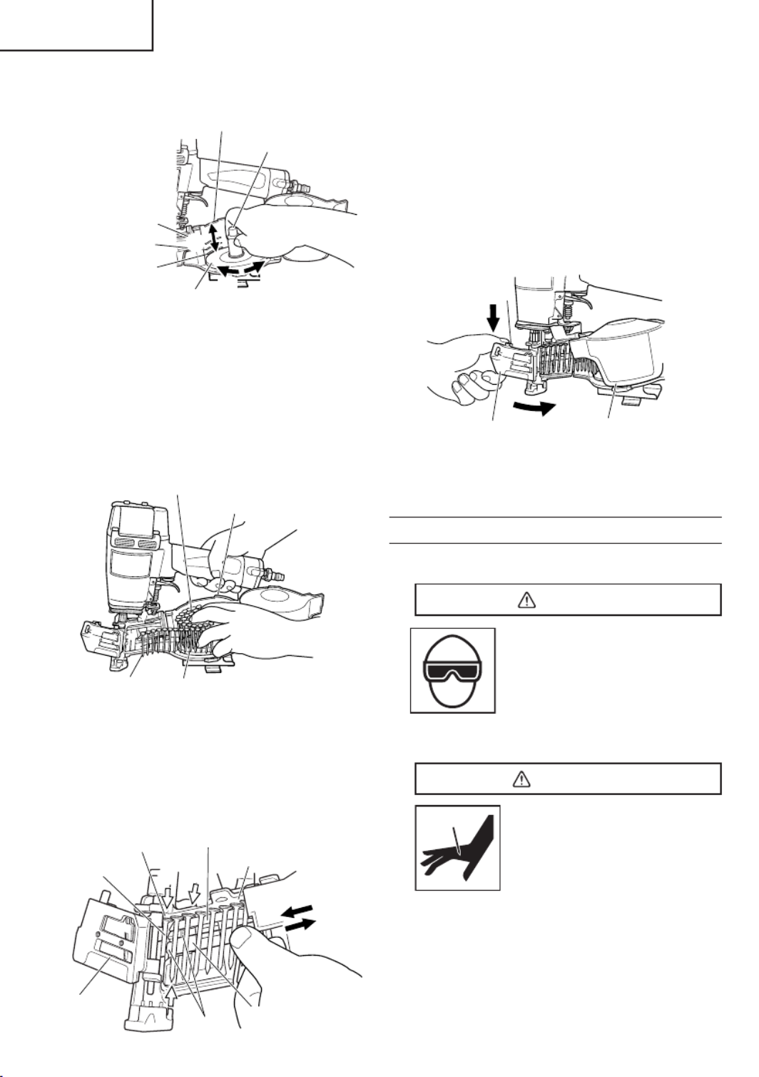
(1) Grip the nail guide and knob with fi nger.
Press the knob down and swing the nail guide open.
And open the magazine cover.
Knob
Nail guide Magazine cover
(2) Adjust the position of the nail holder according to the
nail length.
The nail will not feed smoothly if the nail holder is not
correctly adjusted.
1
Turn the nail holder about 90 degrees
counterclockwise.
2
Move the nail holder up and down to align
the plate of the nail holder with a mark on the
magazine in accordance with the length of the
nails being used.
14
English
NOTE:
Be careful not to deform the collated wires and not to
disengage the nails with the guide surface.
Otherwise, the nail guide will not close correctly.
4
Pulling the nails to the right.
After checking and making sure that the magazine
cover is closed, hook your fi ngers on the nail
guide and knob, turn the nail guide clockwise
while pressing the knob downward, and then
close the nail guide completely.
Knob
Nail Guide Magazine Cover
4
4
(6) Lock the knob completely.
The Nailer is now ready to operate.
NAILER OPERATION
Read section titled “SAFETY” (pages 4 – 8).
DANGER
●
Operators and others in work
area MUST wear safety
glasses with side shields
which conforms to ANSI Z87.1
specifi cations.
Ordinary eyeglasses do not
provide adequate protection.
WARNING
●
Only person who have read
and understand this
MANUAL should operate the
Nailer.
●
NEVER point tool at yourself
or others in work area.
●
Keep fi ngers AWAY from trigger when not
driving nails to avoid accidental discharge.
●
Know and understand what trigger system
you are using.
Please read and understand “Methods of
Operation” below.
3
Turn the nail holder 90 degrees clockwise until
you hear "click".
For 1-1/2" (38 mm)
For 7/8", 1" and 1-1/4"
(22 mm, 25 mm, 32 mm)
Plate
Nail Holder
For 1-3/4" (45 mm)
Magazine
3
21
NOTE:
Before loading nails in the magazine, adjust the
nail holder. If the magazine cover is forcibly closed
without adjusting the nail holder correctly, the nail
holder may be damaged.
(3) Place the nail coil into the magazine.
Insert the fi rst nail into the magazine opening.
First Nail
Magazine
Magazine Opening
Nail
(4) Close the magazine cover.
(5)
1
Uncoil enough nails to reach the driving hole.
2
Insert the fi rst nail into the driving hole and the
second nail between the two pawls of the feeder.
3
Fit the nail heads in the guide slot.
Driving Hole
First Nail
Nail Guide
Guide Slot
Pawl
Guide Surface
Feeder
4
2
3
2
1

15
English
●
Never place your hands or body closer than 8
inches (200 mm) from fi ring head when using.
●
Do not drive nails into other nails; nails can
ricochet and hurt someone.
●
Do not actuate Nailer unless Nailer is placed
fi rmly against the workpiece.
●
In order to avoid double fi re or unwanted
ejection of a nail due to bouncing of the Nailer,
1) do not push Nailer on workpiece with strong
force;
2) take Nailer away from workpiece using
recoil;
3) release trigger quickly when performing
trigger fi re.
●
When working close to an edge of a
workpiece or at steep angles, or driving
fasteners into thin workpiece use care to
minimize chipping, splitting or splintering, or
free fl ight, ricochet or piercing of fasteners,
which may cause injury.
●
Never drive nails from both sides of a wall
at the same time. Nails can be driven into
and through the wall and hit a person on the
opposite side.
●
Never use Nailer which is defective or
operating abnormally.
●
Do not use Nailer as hammer.
●
Disconnect air hose from Nailer when:
1) it is not in use;
2) leaving work area;
3) elevating, lowering or otherwise moving it
to another location;
4) handing it to another person;
5) performing any maintenance or repairs;
6) clearing a jam;
7) Nailer is outside of the operator's
supervision or control;
8) removing nails from the magazine; and
9) adjusting nailing depth.
This metabo HPT nailer has a STANDARD CONTACT TRIP
MECHANISM (Bounce Fire). An OPTIONAL SEQUENTIAL
TRIP MECHANISM kit (SINGLE SHOT) is available as
order part number 878226.
THE STANDARD CONTACT TRIP MECHANISM (Bounce
Fire) is for use where rapid fastener placement is desired
and must be operated in accordance with the following
“METHODS OF OPERATION”.
NOTE:
Be careful that the fi nal nail can be dropped or driven
at an irregular angle.
METHODS OF OPERATION
This Nailer is equipped with the push lever and does
not operate unless the push lever is depressed (upward
position).
There are two methods of operation to drive nails with this
Nailer.
They are:
1. Intermittent operation (Trigger fi re):
2. Continuous operation (Push lever fi re):
(1) Intermittent operation (Trigger fi re)
1
Position the nail outlet on the workpiece with
fi nger off the trigger.
2
Depress the push lever fi rmly until it is completely
depressed.
3
Pull the trigger to drive a nail.
4
Remove fi nger from the trigger.
To drive another nail, move the Nailer along the
workpiece, repeating steps
1
–
4
as required
procedure.
Push Lever
Trigger
3
2
(2) Continuous operation (Push lever fi re)
1
Pull the trigger with the Nailer off the workpiece.
2
Depress the push lever against the workpiece to
drive a nail.
3
Move the Nailer along the workpiece with a
bouncing motion.
Each depression of the push lever will drive a nail.
As soon as the desired number of nails have been
driven, remove fi nger from the trigger.
Previously pull
the trigger
3
1

16
English
WARNING
●
Keep your nger off the trigger except during
fastening operation, because serious injury
could result if the push lever accidentally
contacts you or others in work area.
●
Keep hands and body away from the
discharge area. This metabo HPT nailer may
bounce from the recoil of driving a fastener
and unwanted subsequent fastener may be
driven, possibly causing injury.
●
Some types of loaded nails can spark out of the
muzzle during a nail driving operation. Exercise
caution!
THE OPTIONAL SEQUENTIAL TRIP MECHANISM
(SINGLE SHOT PARTS) is for use where precision
fastener placement is desired and must be operated in
accordance with the following “Method of Operation”.
You must rst depress the push lever (upward position)
where you want to drive a nail and then pull the trigger.
After the each nail is driven, completely release the
trigger and lift the tool off the work surface.
An OPTIONAL SEQUENTIAL TRIP MECHANISM
may reduce the possibility of bodily injury to you or
others in the work area. This is because it is less
likely to drive an unwanted nail if you keep the trigger
pulled and accidentally bump the push lever against
yourself or others. An OPTIONAL SEQUENTIAL TRIP
MECHANISM may also reduce the speed of operation
compared to the standard contact trip mechanism.
NOTE:
●
Both STANDARD CONTACT TRIP MECHANISM and
OPTIONAL SEQUENTIAL TRIP MECHANISM are
safe if used as described above and accroding to all
warnings and instructions.
●
Always handle nails and package carefully. If nails
are dropped, collating wire may be damaged and cut,
which will cause mis-feeding and jamming.
●
After nailing:
1) disconnect air hose from the Nailer;
2) remove all nails from the Nailer;
3) supply 5 – 10 drops of metabo HPT pneumatic
tool lubricant into the air plug on the Nailer; and
4) open the petcock on the air compressor tank to
drain any moisture.
USING THE SHINGLE GUIDE
The shingle guide can be used to control shingle spacing.
Adjust the shingle guide in the following order.
1
DISCONNECT AIR HOSE FROM NAILER
2
Loosen the hex. socket hd. bolt with the accessory
Allen wrench.
3
Place the shingle guide against the bottom of the rst
row of shingles.
4
Adjust the distance between the outlet and the
shingle guide to the proper shingle exposure by
sliding the shingle guide.
5
Tighten the hex. socket hd. bolt.
Second Row
First Row
Outlet
Proper Shingle
Exposure
Disconnect
air hose
Hex. Socket
Hd. Bolt
Shingle Guide
41
3
NOTE:
●
The proper shingle exposure will depend on the type
of shingle and the manufacturer's speci cations.
●
The shingle guide is not to be utilized as an indicator
of nail location.
ADJUSTING THE NAILING DEPTH
WARNING
●
Disconnect the air hose from the nailer
before turning the adjuster.
To assure that each nail penetrates to the same depth, be
sure that:
1) the air pressure to the Nailer remains constant
(regulator is installed and working properly), and
2) the Nailer is always held rmly against the workpiece.
If nails are driven too deep or shallow into the workpiece,
adjust the nailing in the following order.
1
DISCONNECT AIR HOSE FROM NAILER
Disconnect
air hose
15
Adjuster

17
English
2
If nails are driven too deep, turn the adjuster
counterclockwise while pulling it downward.
When the adjuster is released, it returns upward.
Furthermore, turn the adjuster until it reaches a
position where it gets xed with a clock.
Too Deep
Turn Adjuster
Flush
2
If nails are driven too shallow, turn the adjuster
clockwise while pulling it downward.
When the adjuster is released, it return upward.
Furthermore, turn the adjuster until it reaches a
position where it gets xed with a clock.
Turn Adjuster
FlushToo Shallow
2
The adjuster can be exed each at 1/4 rotation.
The adjuster moves approximately 0.25 mm per 1/4
rotation.
3
Stop turning the adjuster when a suitable position is
reached for a nailing test.
4
Connect the air hose.
ALWAYS WEAR EYE PROTECTIOR.
Perform a nailing test.
5
DISCONNECT AIR HOSE FROM NAILER.
6
Choose a suitable position for the adjuster.

18
English
MAINTENANCE
NOTE: The information contained in this Manual is designed to assist you in the safe maintenance of the Nailer.
Some illustrations in this Manual may show details or attachments that diff er from those on your own Nailer.
MAINTENANCE AND INSPECTION
Read section titled “SAFETY” (pages 4 – 8).
WARNING
●
Disconnect air hose and remove all nails
from Nailer when:
1) doing maintenance and inspection; and
2) clearing a jam.
●
Never use gasoline or other highly ammable
liquides for cleaning.
1. Clearing a jam
Remove a jammed nail in the following order:
1
DISCONNECT AIR HOSE.
2
Open the nail guide.
3
Insert a rod into the outlet.
Tap the rod with a hammer.
1
Hammer
Rod
Outlet
Disconnect
air hose
4
Remove the jammed nail with a slotted screw
driver.
Nail
Slotted Screw Driver
5
Cut the deformed collated wire with nippers.
Correct the deformation.
6
In case of frequent jam, contact a metabo HPT
authorized service center.
2. Inspecting the push lever
1
DISCONNECT AIR HOSE.
2
Clean the push lever sliding part.
Lubricate it with metabo HPT pneumatic tool
lubricant.
Lubricate
Disconnect
air hose
1
3. Inspecting the feeders
1
DISCONNECT AIR HOSE.
2
Clean the knob sliding part.
Lubricate it with metabo HPT pneumatic tool
lubricant.
1
Nail Guide
Knob Disconnect
air hose
3
Open the nail guide and remove dust.
Lubricate the nose opening and feeder shaft.
CAUTION
●
Check that the main nail stopper and sub nail
stopper slide smoothly by pushing them with
nger.
If not smooth, nails can be driven at an irregular
angle and hurt someone.

19
English
Nail Guide
Sub Nail Stopper Feeder Shaft
Feeder
Nose Opening
Main Nail Stopper
4
Lubricate the feeding surfaces of the nose and
the nail guide after cleaning.
This promotes smooth operation and prevents
rust.
4. Cleaning and removal of tar and dirt.
Tar and dirt may build up on the nose and push lever.
This can prevent correct operation.
Clean and remove tar and dirt with kerosene, #2 fuel
oil or diesel fuel.
NEVER USE GASOLINE or other highly ammable
liquids.
Vapor of such liquids inside the Nailer could be
ignited by a spark produced during nailing, which can
cause an explosion.
1
Immerse only the area around the outlet in
solvent.
Do not immerse the magazine or body.
Plastic parts and O-ring may be damaged.
Body
Push
Lever
Outlet
Magazine
Nose
2
Dry off the Nailer before use. Any oil lm left after
cleanup will accelerate the tar buildup, and the
Nailer will requite more frequent re-cleaning.
3
Make sure the push lever operates properly.
WARNING
●
Never use Nailer unless push lever is
operating properly.
NOTE:
Solvents sprayed on nose to clean and free up the
push lever may have the opposite eff ect. The solvent
may soften the tar on the shingles and cause tar
buildup to be accelerated. Dry operation is better.
5. Inspecting the magazine
1
DISCONNECT AIR HOSE.
2
Clean the magazine. Remove paper chips or
wooden chips which may have accumulated in
the magazine.
6. Storing
○
When not in use for an extended period, apply a
thin coat of the lubricant to the steel parts to avoid
rust.
○
Do not store the Nailer in a cold weather
environment.
Keep the Nailer in a warm area.
○
When not in use, the Nailer should be stored in a
warm and dry place.
Keep out of reach children.
7. WARNING LABEL
Do not use the Nailer with missing or damaged
WARNING LABEL.
A new WARNING LABEL is available from a
metabo HPT authorized service center.
Warning
Label
8. Maintenance chart (See page 20)
9. Operator troubleshooting (See page 21)

20
English
CAUTION
●
In the operation and maintenance of power tools,
the safety regulations and standards prescribed
in each country must be observed.
SERVICE AND REPAIRS
WARNING
●
Only service personnel trained by
metabo HPT, distributor or employer
shall repair the Nailer.
●
Use only parts supplied or recommended by
metabo HPT for repair.
All quality Nailers will eventually require servicing or
replacement of parts because of wear from normal use.
NOTE:
Speci cations are subject to change without any
obligation on the part of metabo HPT.
Maintenance chart
ACTION WHY HOW
Drain air line lter daily. Prevent accumulation of moisture
and dirt.
Open manual petcock.
Keep lubricator lled. Keep the Nailer lubricated. Fill with metabo HPT pneumatic tool
lubricant.
Clean lter element and blow air
through lter in direction opposite to
normal ow daily.
Prevent clogging of lter with dirt. Follow manufacturer’s instructions.
Clean magazine and feeder
mechanism.
Prevent a jam. Blow clean daily.
Keep push lever working properly. Promote operator safety and effi cient
Nailer operation. Blow clean daily.
Lubricate the Nailer after nailing. Extend the Nailer life. Supply 5 – 10 drops of lubricant into
the Nailer.
Drain air compressor daily. Keep the Nailer operated properly. Open petcock on air compressor
tank.

21
English
Operator troubleshooting
Most minor problems can be resolved quickly and easily using the table below.
If problems persist, contact a metabo HPT authorized service center for assistance.
PROBLEM CHECK METHOD CORRECTION
Nailer operates, but no nail is driven. Open nail guide. Check for a jam Clear a jam per page 18.
Check function of feeder per page 18. Clean and lubricate.
Check for proper nails. Use only recommended nails.
Weak drive.
Slow to cycle.
Check air pressure. Increase air pressure. (Do not exceed
120 psi (8.3 bar 8.5 kgf/cm 2).)
Check position of adjuster per page
16. Readjust
——— Use metabo HPT pneumatic tool
lubricant.
Driver blade worn? Contact metabo HPT for replacement.
Piston O-ring worn or damaged?
Drives too deep. Check air pressure. Reduce air pressure.
(Adjust 70 – 120 psi
(4.9 – 8.3 bar 5 – 8.5 kgf/cm2))
Check position of adjuster per page
16.
Readjust
Skipping nails. Intermittent feed. Check for proper nails. Use only recommended nails.
Check function of feeder per page 18. Clean and lubricate.
——— Use metabo HPT pneumatic tool
lubricant.
Check position of nail holder in
magazine per page 13.
Adjust nail holder to proper position.
Piston O-ring cut or heavily worn? Contact metabo HPT for replacement.
Nails jam.
Driven nail is bent.
Check for proper nails. Use only recommended nails.
Driver blade worn? Contact metabo HPT for replacement.
Drives properly during normal
operation, but does not drive fully at
faster nailing speeds.
Check inside diameter of air hose. Use larger air hose.

22
Français
ATTENTION : UTILISATEURS DE CLOUEURS metabo HPT
(Veuillez lire attentivement ces informations pour garantir une
utilisation satisfaisante et en toute sécurité.)
Ce cloueur metabo HPT possède un MÉCANISME DE DÉCLENCHEMENT PAR CONTACT STANDARD (activation par band).
Il existe des lots de MÉCANISME DE DÉCLENCHEMENT SÉQUENTIEL EN OPTION (CLOUAGE SIMPLE) ndiqués ci-dessus.
Modèles No. de commande de pièce
NR83A, NR83AA, NV83A, NV65AC, VH-650, NT65A2, NV50AA, NV50A1, NV50AP,
NR83AA2, N5008AC, NV50AP2, NV83A2, N5024A
876762
NV45AB, NV45AB2, NV45AE 878226
NR90AC, NV65AH, NR90AA, NV45AC, NR90AC2 881973
NT65AA, NT65MA 880414
NV75AG 883991
Pour les commandes aux Etats-Unis, appeler sans frais le 1-800-706-7337. Au Canada, appeler sans frais le
1-800-970-2299.
On utilisera LE MÉCANISME DE DÉCLENCHEMENT PAR CONTACT STANDARD (activation par band) pour
eff ectuer un clouage rapide, et en respectant la “méthode d’utilisation” ci-dessous.
Ce cloueur metabo HPT possède un levier-poussoir, et il ne fonctionne pas tant que le levier-poussoir n’est pas
enfoncé (position “haut”). Il y a deux façons d’eff ectuer le clouage avec ce cloueur.
1. Clouage intermittent (déclenchement par gâchette)
2. Clouage séquentiel (déclenchement par levier-poussoir)
(1) Clouage intermittent (déclenchement par gâchette)
1
Placer la sortie des clous contre la pièce en retirant le doigt de la gâchette.
2
Appuyer à fond sur le levier-poussoir jusqu’à ce qu’il soit complètement enfoncé.
3
Tirer sur la gâchette pour enfoncer un clou.
4
Retirer le doigt de la gâchette.
Pour enfoncer un autre clou, déplacer le cloueur sur la pièce et recommencer.
(2) Clouage séquentiel (déclenchement par levier-poussoir)
1
Tirer sur la gâchette alors que le levier-poussoir est dirigé vers la pièce mais sans la toucher.
2
Appuyer sur le levier-poussoir avec le cloueur contre la pièce pour enfoncer un clou.
3
Déplacer successivement le cloueur sur la pièce en un mouvement de bonds. Chaque pression sur le
levier-poussoir enfonce un clou.
Dès que le nombre de clous voulu a été enfoncé, retirer le doigt de la gâchette.
AVER TISSEMENT
: Ne pas mettre le doigt sur la gâchette sauf pendant une opération de
clouage, car un contact accidentel du levier-poussoir sur l’opérateur ou sur les personnes
alentour pourrait entraîner des blessures graves.
AVER TISSEMENT
: Ne pas approcher les mains ni le corps de la section de sortie des clous. Le
cloueur avec mécanisme de déclenchement par contact risque de faire un bond après avoir
enfoncé un clou, ce qui pourrait enfoncer un autre clou et provoquer des blessures.
On utilisera LE MÉCANISME DE DÉCLENCHEMENT SÉQUENTIEL EN OPTION (CLOUAGE SIMPLE) pour
eff ectuer un clouage précis et en respectant la “méthode de fonctionnement” ci-dessous.
Appuyer tout d’abord sur le levier-poussoir (position “haut”) à l’endroit où l’on veut enfoncer le clou, puis
tirer sur la gâchette. Après avoir enfoncé chaque clou, relâcher complètement la gâchette et relever l’outil de
la surface de travail. Le MÉCANISME DE DÉCLENCHEMENT SÉQUENTIEL EN OPTION réduit les risques de
blessures pour l’opérateur et les personnes qui se trouvent dans l’aire de travail. En eff et, il risque moins d’enfoncer
accidentellement un clou si l’on garde le doigt sur la gâchette et qu’on appuie accidentellement le levier-poussoir
contre soi ou contre une autre personne. LE MÉCANISME DE DÉCLENCHEMENT SÉQUENTIEL EN OPTION
réduit également la vitesse de clouage par rapport au mécanisme de déclenchement par contact standard.
REMARQUE : LE MÉCANISME DE DÉCLENCHEMENT PAR CONTACT STANDARD et LE MÉCANISME DE
DÉCLENCHEMENT SÉQUENTIEL EN OPTION sont tous deux parfaitement sûrs s’ils sont utilisés
conformément aux avertissements et aux instructions.

23
Français
INFORMATION IMPORTANTE DE SÉCURITÉ
Lire et bien assimiler toutes les étiquettes de l’outil ainsi que toutes les instructions de fonctionnement,
les consignes de sécurité et les avertissements de ce mode d’emploi avant d’utiliser ou d’entretenir ce
cloueur.
Le non respect des avertissements pourrait entraîner la MORT ou des BLESSURES GRAVES.
La plupart des accidents résultant de l’utilisation ou de l’entretien des cloueurs sont dus au non respect de certaines
consignes et précautions de sécurité élémentaires. Un accident peut souvent être évité en reconnaissant une situation
potentiellement dangereuse avant qu’elle ne se produise, et en respectant les procédures de sécurité applicables.
Les consignes de sécurité élémentaires sont données dans la section “SECURITE” du manuel et dans les sections
relatives aux instructions d’utilisation et d’entretien.
Les dangers à éviter pour empêcher tout risque de blessures ou de dommage de l’outil sont identi és par les mots
DANGER et AVERTISSEMENT, sur le cloueur et dans ce manuel.
NE JAMAIS utiliser ce cloueur pour des applications autres que celles qui sont spéci ées dans ce manuel.
DEFINITION DES MOTS DE SIGNALISATION
DANGER indique une situation imminente dangereuse qui, si elle n’est pas évitée, entraînera la mort ou des
blessures graves.
AVERTISSEMENT indique une situation potentiellement dangereuse qui, si elle n’est pas évitée, risque d’entraîner
la mort ou des blessures graves.
ATTENTION indique une situation potentiellement dangereuse qui, si elle n’est pas évitée, risque d’entraîner des
blessures légères ou modérées, ou d’endommager l’outil.
REMARQUE met en relief les informations essentielles.
EXPLICATION DE L’ACTION DE CLOUAGE DU CLOUEUR metabo HPT
○
MÉCANISME DE DÉCLENCHEMENT PAR CONTACT :
Appuyer tout d’abord le levier-poussoir contre le bois, puis tirer sur la gâchette pour enfoncer le clou.
Tirer tout d’abord sur la gâchette, puis appuyer le levier-poussoir contre le bois pour enfoncer le clou.
Si la gâchette est maintenue tirée, un clou s’enfonce chaque fois que l’on appuie le levier-poussoir contre le bois.

24
Français
SECURITE
CONSIGNES DE SÉCURITÉ IMPORTANTES POUR L’UTILISATION DU
CLOUEUR
CONSIGNES RELATIVES À UN RISQUE D’INCENDIE, DE CHOC ÉLECTRIQUE OU DE BLESSURES
CORPORELLES
●
Généralités
A n de réduire les risques de choc électrique, d’incendie et de blessures physiques, LIRE TOUTES LES
INSTRUCTIONS AVANT D’UTILISER L’OUTIL.
DANGER
1. LES OPÉRATEURS ET LES AUTRES PERSONNES
DANS L’AIRE DE TRAVAIL DOIVENT PORTER
UNE PROTECTION OCULAIRE (LUNETTES DE
PROTECTION AVEC ÉCRANS LATÉRAUX).
Quand on utilise le cloueur, toujours
porter des lunettes de protection avec
visières latérales, et veiller à ce que les
autres personnes dans la zone de travail
en portent également.
Les lunettes de protection devront
respecter les exigences de l’ANSI
(American National Standards Institute)
Z87.1 et assurer la protection contre les
projections de particules arrivant par
l’avant et par le côté.
AVERTISSEMENT
3. NE JAMAIS DIRIGER L’OUTIL VERS SOI NI VERS
QUELQU’UN D’AUTRE DANS L’AIRE DE TRAVAIL.
Toujours supposer que le cloueur
renferme des clous.
Ne jamais diriger le cloueur vers soi, ni
vers quelqu’un d’autre, qu’il renferme des
clous ou non.
Si l’on enfonce des clous par erreur, cela
risque de provoquer des blessures graves.
Ne jamais s’amuser avec le cloueur.
Le cloueur est un instrument de travail.
Le respecter.
4. NE PAS PLACER LE DOIGT SUR LA GÂCHETTE
ET MAINTENIR LES DOIGTS ÉLOIGNÉS DE
CELLE-CI QUAND ON N’EFFECTUE PAS DE
CLOUAGE POUR ÉVITER TOUT RISQUE DE
CLOUAGE ACCIDENTEL.
Les lunettes ordinaires ne fournissent pas une
protection adéquate.
L’employeur doit veiller à ce que la personne qui
utilise le cloueur et les autres personnes dans l’aire
de travail portent des lunettes de protection.
2. NE JAMAIS UTILISER DE GAZ RÉACTIFS NI
AUCUN AUTRE GAZ EN BOUTEILLE. IL
POURRAIT SE PRODUIRE UNE EXPLOSION.
Ne jamais utiliser de gaz réactifs (tels
que l’oxygène), de gaz combustibles
ni aucun autre gaz en bouteille comme
source d’alimentation du cloueur.
L’utilisation de ces gaz serait
dangereuse, car le cloueur exploserait.
Utiliser exclusivement de l’air comprimé
propre, sec et régulé.
Ne jamais transporter l’outil avec le doigt
sur la gâchette, car on risquerait d’enfoncer
accidentellement un clou et de se blesser ou de
blesser quelqu’un d’autre.
Toujours transporter le cloueur exclusivement par sa
poignée.
5. CONNAÎTRE ET COMPRENDRE LE SYSTÈME DE
GÂCHETTE UTILISÉ.
Lire et bien assimiler la section intitulée “MÉTHODES
D’UTILISATION”. (pages 36 – 37)
6. NE PAS ENTRER EN CONTACT AVEC L’EMBOUT
DE SÉCURITÉ (LEVIER-POUSSOIR) QUAND ON
N’EFFECTUE PAS DE CLOUAGE.

27
Français
(2) Ne jamais utiliser de gaz réactifs (tels que
l’oxygène), de dioxyde de carbone, de gaz
combustibles ou tout autre gaz en bouteille
comme source d’alimentation du cloueur.
L’utilisation de ces gaz pourrait provoquer une
explosion et causer de graves blessures physiques.
6. Autres
(1) Faire attention aux doubles activations et aux
coups par le cloueur suite au retour brutal («
rappel »).
Après avoir enfoncé un clou, le cloueur peut eff ectuer
un rappel causant son éloignement de la surface de
travail.
Pour réduire le risque de blessure, toujours gérer le
rappel en :
1) maintenant toujours le contrôle du cloueur.
2) laissant le rappel éloigner le cloueur de la surface
de travail.
3) ne résistant pas au rappel de sorte que le cloueur
sera refoulé contre la surface de travail. Dans
« MÉCANISME DE DÉCLENCHEMENT PAR
CONTACT », si on laisse le levier-poussoir entrer
de nouveau en contact avec la surface de travail
avant de relâcher la gâchette, un clouage imprévu
se produira. A n d’éviter ces doubles activations
indésirables,
○
Fonctionnement intermittent (déclenchement par
gâchette)
1
Tirer sur la gâchette rapidement et fermement.
2
Relâcher la gâchette RAPIDEMENT.
○
Fonctionnement continu (déclenchement par
levier-poussoir)
1
Ne pas appuyer le cloueur trop fort contre le
bois.
2
Eloigner le cloueur du bois car il eff ectue un
rappel après le clouage.
4) éloignant le visage et les parties du corps du
cloueur.
(2) Ne jamais utiliser de coupleur NON dégageant
sur le cloueur. Si l’on utilise un coupleur non
dégageant sur le cloueur, celui-ci risque de rester
chargé d’air après le débranchement et, par
conséquent, d’enfoncer un clou même après avoir
été débranché. Le cloueur et le tuyau d’air doivent
avoir un coupleur de tuyau de façon à ce que toute
la pression soit évacuée du cloueur quand on
débranche le joint de couplage.
(3) Véri er le levier-poussoir avant l’utilisation.
S’assurer que le levier-poussoir fonctionne
correctement, et qu’il ne soit pas inutilisable,
déconnecté, ou modi é. (Le levier-poussoir est
parfois appelé "sécurité".) Ne jamais utiliser le cloueur
si le levier-poussoir ne fonctionne pas correctement.
Un clou pourrait s’enfoncer accidentellement. Ne
pas modi er ou retirer le levier-poussoir, car sinon il
pourrait devenir inutilisable.
(4) Veiller à ce que toutes les vis et les couvercles
soient en place et bien serrés. Veiller à ce que
les vis et les couvercles soient solidement xés.
Les véri er périodiquement. Ne jamais utiliser le
cloueur si des pièces sont manquantes ou sont
endommagées.
(5) Ne pas charger de clous si la gâchette ou le
levier-poussoir sont enfoncés. Quand on charge
des clous dans le cloueur ou qu’on raccorde le tuyau
d’air,
1) ne pas appuyer sur la gâchette;
2) ne pas actionner le levier-poussoir; et
3) diriger le cloueur vers le bas.
(6) Éloigner les mains et le corps de la tête de
clouage pendant l’utilisation. Ne jamais approcher
les mains ni les pieds à moins de 8 pouces (200 mm)
de la tête de clouage. Il y a un risque de blessure
grave si les clous sont déviés par la pièce ou qu’ils
sont déportés au-delà du point d’entrée.
(7) Quand on travaille près du bord d’une pièce
ou à un angle prononcé, ou quand on enfonce
des clous dans une pièce ne, prendre soin de
minimiser le déchiquetage, le fractionnement
ou l’éclatement, ou le vol libre, le ricochet ou
le perçage des clous, pouvant provoquer des
blessures.
(8) Ne jamais enfoncer de clous des deux côtés d’un
mur en même temps. Les clous pourraient traverser
le mur et blesser quelqu’un de l’autre côté.
(9) Redoubler de précaution quand on cloue dans
des murs existants ou d’autres zones mortes
pour prévenir le contact avec des objets cachés
ou des personnes de l’autre côté (par ex.,
câbles, tuyaux).
(10) Véri er s’il y a des ls sous tension. Pour éviter
tout risque d’électrocution grave, véri er s’il y a des
ls sous tension dissimulés dans le mur, le plancher
ou le plafond. Couper le disjoncteur pour s’assurer
qu’il n’y a pas de ls sous tension.
SECURITE — Suite
AVERTISSEMENT

28
Français
RESPONSABILITÉS DE L’EMPLOYEUR, DU PROPRIÉTAIRE DE L’OUTIL ET DE
L’OPÉRATEUR DE L’OUTIL
SECURITE — Suite
AVERTISSEMENT
1. Veiller à ce que ce MANUEL reste à la disposition des
personnes qui doivent utiliser ou entretenir le cloueur.
2. Former l’opérateur à l’utilisation sécuritaire du
cloueur comme décrit dans ce MANUEL.
3. Veiller à ce que seules les personnes qui ont lu et
compris ce MANUEL utilisent le cloueur.
4. Veiller à ce que les cloueurs soient utilisés
exclusivement lorsque les opérateurs et les autres
personnes présentes dans l’aire de travail portent
des LUNETTES DE PROTECTION et un autre
équipement de protection individuelle approprié
comme une PROTECTION POUR LA TÊTE, LES
OREILLES ET LES PIEDS.
5. Obliger les opérateurs et les autres personnes
présentes dans l’aire de travail à porter des
LUNETTES DE PROTECTION.
6. Veiller à ce que les cloueurs soient conservés en bon
état de marche comme décrit dans ce MANUEL.
7. Entretenir les cloueurs correctement.
8. Veiller à ce que seul le personnel quali é répare les
cloueurs.
9. Veiller à ce que les cloueurs qui ont besoin d’être
réparés soient retirés du service et que des étiquettes
et une séparation physique soient utilisées comme
moyen de contrôle.
CONSERVER CE MANUEL ET
LE METTRE A LA DISPOSITION DES
UTILISATEURS!
(11) Ne pas lever, tirer ou abaisser le cloueur par le
tuyau.
(12) Ne pas débrancher le tuyau d’air du cloueur avec
le doigt sur la gâchette. Le pourrait se déclencher
lorsque l’alimentation d’air sera à nouveau raccordée.
(13) Manipuler le cloueur correctement. Utiliser le
cloueur en suivant les instructions du manuel. Ne
jamais permettre que le cloueur soit utilisé par des
enfants, des personnes nonfamiliarisées avec son
fonctionnement ou du personnel non autorisé.
(14) Ne jamais utiliser le cloueur pour des
applications autres que celles spéci ées dans le
présent manuel.
(15) Ne jamais modi er ni altérer un cloueur. Cela
pourrait provoquer un mauvais fonctionnement et
entraîner des blessures physiques.
(16) Fermer le guide-clous et ne pas l’ouvrir pendant
le fonctionnement. Si l’on enfonce des clous avec
le guide-clous ouvert, ils risquent d’être déviés de la
pièce.

29
Français
UTILISATION
REMARQUE: Les informations contenues dans ce manuel ont pour but d’aider l’opérateur à utiliser le cloueur en toute
sécurité.
Certaines des illustrations du manuel peuvent montrer des détails ou des accessoires qui diff èrent de
ceux de votre cloueur.
NOM DES PIECES
Bec
Piston
Joint torique
du piston
Couvercle
d’échappement
Lame
d’entraînement
Tête de clouage
(sortie)
Corps
Gâchette
Couvercle de
magasin
Porte-clous
Bouch d'air
Bouton
Levier-
poussoir
Magasin
Chargeur
Couvercle supérieur
Capuchon
Guide-clous Guide à
bardeau

30
Français
SPECIFICATIONS
Pression d’utilisation 70 – 120 psi (4.9 – 8.3 bars, 5 – 8.5 kgf/cm 2)
Dimensions
Longueur × Hauteur × Largeur 9-27/32" × 10-3/8" × 4-5/8"
(250 mm × 264 mm × 117 mm)
Poids 5.7 lbs (2.6 kg)
Contenance de clous 120 clous (1 bobine)
Consommation d’air
.046 ft 3/cycle à 100 psi
(1.3 l/cycle à 6.9 bars)
(1.3 l/cycle à 7 kgf/cm 2)
Arrivée d’air Filetage 3/8 NPT
SELECTION DES CLOUS
AVERTISSEMENT
●
Bien utiliser exclusivement les clous metabo HPT d’origine avec le NV45AB2. L’utilisation d’autres clous
risque de provoquer un mauvais fonctionnement de l’outil et/ou une rupture des clous, et d’entraîner des
blessures.
Seuls les clous indiqués dans le tableau ci-dessous pourront être utilisés avec ce cloueur.
Bobine de clous xés par l Min. Max.
ACCESSOIRES
AVERTISSEMENT
●
Les accessoires autres que ceux indiqués ci-dessous risquent de mal fonctionner et de provoquer des
blessures.
ACCESSOIRES STANDARD
1
1
Lunettes de protection ............................................. 1

31
Français
ACCESSOIRES EN OPTION
... vendus séparément
○
Kit de mécanisme de declenchement séquentiel
(N° de code 878226)
○
Huile de machine pneumatique
Alimenteur d’huile 1 oz (30 cc) (N° de code 877153)
Alimenteur d’huile 4 oz (120 cc) (N° de code 874042)
Alimenteur d’huile 1 quart (1 l) (N° de code 876212)
REMARQUE: Les accessoires sont sujets à
modi cation sans préavis et sans aucune
obligation de la part de metabo HPT.
APPLICATIONS
○
Fixation de bardeaux de toiture en asphalte dans la
construction des bâtiments.
○
Fixation des panneaux isolants dans la construction
des bâtiments.
AVANT L’UTILISATION
Lire la section intitulée “SECURITE” (pages 24 – 28).
Bien véri er les points suivants avant de travailler.
ENVIRONNEMENT DE TRAVAIL
AVERTISSEMENT
●
Pas de gaz ou liquides in ammables, ni
aucun autre objet in ammable sur le chantier.
●
Evacuer les enfants et les personnes non
autorisées de l’aire de travail.
ALIMENTATION D’AIR
DANGER
●
NE JAMAIS utiliser de gaz
réactifs ni aucun autre gaz en
bouteille. Il pourrait se
produire une explosion.
AVERTISSEMENT
●
Ne jamais raccorder le cloueur à une
pression qui risque de dépasser 200 psi
(13.7 bars 14 kgf/cm 2) si une défaillance du
régulateur se produit.
●
Ne jamais utiliser de coupleur non dégageant
sur le cloueur.
1. Alimentation
○
Utiliser exclusivement de l’air comprimé propre, sec
et régulé avec ce cloueur.
○
Les compresseurs d’air utilisés pour alimenter
l’air comprimé au cloueur devront respecter les
exigences ANSI B19.3 “Normes de sécurité pour les
compresseurs des industries de transformation”.
○
L’humidité ou l’huile dans le compresseur d’air
peuvent accélérer l’usure et la corrosion du cloueur.
Purger tous les jours.
2. Filtre-régulateur-lubri cateur
○
Utiliser un régulateur d’une pression comprise entre
0 – 120 psi (0 – 8.3 bars 0 – 8.5 kgf/cm 2).
○
Les unités ltre-régulateur-lubri cateur procureront
les conditions optimales du cloueur et accroîtront sa
durée de service.
Toujours les utiliser.
Filtre ............... Le ltre enlève l’humidité et la saleté
mélangées à l’air comprimé.
Purger tous les jours, sauf si l’outil
possède une purge automatique.
Nettoyer régulièrement le ltre.
Régulateur ...... Le régulateur contrôle la pression
de fonctionnement a n d’assurer la
sécurité du cloueur.
Inspecter le régulateur avant le
travail pour s’assurer qu’il fonctionne
correctement.
Lubri cateur ... Le lubri cateur alimente de l’huile
vaporisée au cloueur.
Inspecter le lubri cateur avant le travail
pour s’assurer que l’alimentation
d’huile est adéquate.
Utiliser une huile de machine
pneumatique metabo HPT.
Côté cloueur
Filtre
Lubri cateur
Côté
compresseur
Régulateur
3. Tuyau d’air
Les tuyaux d'alimentation d’air comprimé doivent
avoir une pression de travail minimum égale ou
supérieure à la pression de la source d'alimentation
si une défaillance du régulateur se produit, ou égale
ou supérieure à 150 psi (10.4 bar 10.6 kgf/cm 2), à
savoir la plus élevée.

32
Français
4. Consommation d’air
Sélectionner la taille du compresseur en se reportant
au tableau de consommation d’air et aux formules de
taille du compresseur.
Tableau de consommation d’air
Pression de
fonctionnement
psi
(bar)
(kgf/cm2)
80
(5.5)
(5.6)
90
(6.2)
(6.3)
100
(6.9)
(7)
Consommation d’air ft3/cycle
(I/cycle) .033
(.93) .039
(1.1) .046
(1.3)
Formules de taille du compresseur d’air
Quantité d’air requise
=nombre de clous
× clous moyens enfoncés par minute par le
cloueur
× consommation d’air à une pression donnée
× facteur de sécurité (toujours 1.2)
Example: 2 cloueurs fonctionnant à 100 psi et
enfonçant 30 clous par minute
Quantité d’air requise
=2 × 30 × .046 (1.3) × 1.2
=3.3 CFM (ft 3/mn) (94 l/mn)
Eff ectuer le calcul ci-dessus pour obtenir un
compresseur fournissant les 3.3 CFM d’air
nécessaires.
GRAISSAGE
Il est essentiel que le cloueur soit graissé correctement.
Si le cloueur est mal graissé, il ne fonctionnera pas
correctement et les pièces s’useront prématurément.
○
Utiliser une huile de machine metabo HPT.
Ne pas utiliser d’huile détergente ni d’additifs. Ces
lubri ants endommageraient les joints toriques et les
autres pièces en caoutchouc. Cela provoquerait un
mauvais fonctionnement du cloueur.
○
Toujours utiliser des unités ltre-régulateur-
lubri cateur.
Veiller à ce que le régulateur soit toujours plein d’huile
de machine pneumatique metabo HPT.
○
Si l’on ne possède pas de lubri cateur, mettre 5 à 10
gouttes d’huile de machine pneumatique metabo HPT
dans le bouchon d’air du cloueur deux fois par jour.
ENTRETIEN PAR TEMPS FROID
○
Ne pas ranger le cloueur dans un environnement
froid.
Le laisser dans un endroit chaud jusqu’à ce que l’on
soit prêt à travailler.
○
Si le cloueur est déjà froid, l’amener dans un endroit
chaud et le laisser réchauff er avant de l’utiliser.
1
Réduire la pression d’air à 64 psi (4.4 bars
4.5 kgf/cm 2).
2
Sortir tous les clous du cloueur.
3
Raccorder le tuyau d’air et faire un essai de
clouage (clouage à blanc).
La pression d’air inférieure sera suffi sante pour le
clouage à blanc.
Les opérations à vitesse lente ont tendance à
chauff er les pièces mobiles.
ATTENTION
●
Ne pas faire un essai de clouage à blanc à haute
pression.
ESSAI DU CLOUEUR
DANGER
●
Les opérateurs et les autres
personnes dans l’aire de
travail DOIVENT porter des
lunettes de protection avec
visières latérales respectant
les exigences ANSI Z87.1.
Les lunettes ordinaires ne
fournissent pas une
protection adéquate.
AVERTISSEMENT
●
Ne jamais utiliser le cloueur si le levier-
poussoir ne fonctionne pas correctement.
Avant de commencer le travail proprement dit, faire
un essai de clouage en véri ant les points ci-dessous.
Eff ectuer les essais dans l’ordre indiqué.
S’il se produit un fonctionnement anormal, cesser
immédiatement d’utiliser le cloueur et contacter un
service après-vente agréé metabo HPT.
(1) DEBRANCHER LE TUYAU D’AIR DU CLOUEUR.
SORTIR TOUS LES CLOUS DU CLOUEUR.
□
TOUTES LES VIS DOIVENT ETRE SERREES A
FOND.
Si certaines vis sont relâchées, les revisser.

33
Français
□
LE LEVIER-POUSSOIR ET LA GACHETTE
DOIVENT FONCTIONNER AVEC SOUPLESSE.
Levier-
poussoir
Gâchette
Ne pas raccorder
le tuyau d’air
(2) Régler la pression d’air sur 70 psi (4.9 bar
5 kgf/cm 2).
Raccorder le tuyau d’air.
□
LE CLOUEUR NE DOIT PAS AVOIR DE FUITE
D’AIR.
Diriger le cloueur vers le bas et tirer sur la gâchette.
□
LE CLOUEUR NE DOIT PAS FONCTIONNER.
Tirer sur la gâchette
(3) Retirer le doigt de la gâchette et appuyer le levier-
poussoir contre le bois.
□
LE CLOUEUR NE DOIT PAS FONCTIONNER.
Ne pas tirer sur la
gâchette
Actionner
le levier-
poussoir
(4) Sans toucher la gâchette, actionner le levier-poussoir
contre la pièce.
Tirer sur la gâchette.
□
LE CLOUEUR DOIT FONCTIONNER.
(5) Le cloueur ne touchant plus la pièce, tirer sur la
gâchette.
Actionner le levier-poussoir contre la pièce.
□
LE CLOUEUR DOIT FONCTIONNER.
(6) Si l’on ne remarque aucun fonctionnement anormal,
on pourra mettre des clous dans le cloueur.
Enfoncer les clous dans un matériau du même type
que celui du travail proprement dit.
□
LE CLOUEUR DOIT FONCTIONNER
CORRECTEMENT.
RÉGLAGE DE LA PRESSION D’AIR
AVERTISSEMENT
●
Ne pas dépasser
120 psi (8.3 bars
8.5 kgf/cm 2).
Régler la pression d’air à la pression de travail
recommandée de 70 – 120 psi (4.9 – 8.3 bars
5 – 8.5 kgf/cm 2) en fonction de la longueur des clous et de
la dureté du matériau.
La pression d’air correcte est la pression la plus basse
capable d’eff ectuer le travail. L’utilisation d’une pression
d’air supérieure à la pression nécessaire fatiguera
inutilement le cloueur.
CHARGEMENT DES CLOUS
AVERTISSEMENT
●
Lors du chargement des clous dans le
cloueur,
1) ne pas appuyer sur la gâchette;
2) ne pas actionner le levier-poussoir; et
3) diriger le cloueur vers le bas.
(1) Saisir le guide-clous et le bouton avec les doigts.
Pousser le bouton vers le bas et ouvrir le guide-clous.
Ouvrir le couvercle du magasin.

34
Français
Bouton
Guide-clous Couvercle du
magasin
(2) Ajuster la position du porte-clous en fonction de la
longueur des clous.
Les clous ne seront pas chargés en douceur si le
porte-clous n’est pas correctement ajusté.
1
Tourner le porte-clous d’environ 90 degrés dans
le sens contraire des aiguilles d’une montre.
2
Monter et descendre le porte-clous pour aligner
sa plaque avec la marque du magasin en fonction
de la longueur des clous utilisés.
3
Tourner le porte-clous de 90 degrés dans le sens
des aiguilles d’une montre jusqu’à ce qu’un “clic”
soit entendu.
Magasine
Pour 7/8", 1" et 1-1/4"
(22 mm, 25 mm, 32 mm)
Pour 1-1/2" (38 mm)
Plateau
Pour 1-3/4" (45 mm)
1
2
Porte-clous
3
REMARQUE:
Avant de charger les clous dans le magasin, ajuster
le porte-clous. Si le couvercle du magasin est fermé
en force sans que le porte-clous n’ait été ajusté
correctement, le porte-clous risque d’être endommagé.
(3) Placer le rouleau de clous dans le magasin
Insérer le premier clou dans l’ouverture du magasin.
Premier clou
Magasin
Ouverture du magasin
Clous
(4) Refermer le couvercle du magasin.
(5)
1
Dérouler suffi samment de clous pour atteindre le
trou de clouage.
2
Insérer le premier clou dans le trou de clouage
et le second clou entre les deux cliquets du
chargeur.
3
Ajuster la tête du clou dans la fente-guide.
Trou de clouage
Premier clou
Guide-clous
Fente-guide
Cliquet
Surface du guide
Chargeur
4
2
3
2
1
REMARQUE:
Faire attention de ne pas déformer les ls de xation
et de ne pas désengager les clous de la surface du
guide.
Sinon, le guide-clous ne fermera pas correctement.
4
En tirant les clous sur la droite.
Après avoir véri é que le couvercle du magasin
est bien fermé, accrocher les doigts sur le guide-
clous et le bouton, tourner le guide-clous dans le
sens des aiguilles d’une montre tout en appuyant
sur le bouton, puis refermer le couvercle du
magasin à fond.
Termékspecifikációk
| Márka: | HiKOKI |
| Kategória: | tűzőgép |
| Modell: | NV45AB2 |
Szüksége van segítségre?
Ha segítségre van szüksége HiKOKI NV45AB2, tegyen fel kérdést alább, és más felhasználók válaszolnak Önnek
Útmutatók tűzőgép HiKOKI

23 Augusztus 2024
23 Augusztus 2024
23 Augusztus 2024
21 Augusztus 2024
21 Augusztus 2024
21 Augusztus 2024
21 Augusztus 2024
21 Augusztus 2024
21 Augusztus 2024
21 Augusztus 2024
Útmutatók tűzőgép
- tűzőgép Whirlpool
- tűzőgép Milwaukee
- tűzőgép Parkside
- tűzőgép Bosch
- tűzőgép Einhell
- tűzőgép Makita
- tűzőgép Fellowes
- tűzőgép Rapid
- tűzőgép Sencor
- tűzőgép Genesis
- tűzőgép Güde
- tűzőgép Hitachi
- tűzőgép Rexel
- tűzőgép Klein Tools
- tűzőgép Workzone
- tűzőgép Fieldmann
- tűzőgép PowerPlus
- tűzőgép DEDRA
- tűzőgép Metabo
- tűzőgép Powerfix
- tűzőgép RYOBI
- tűzőgép Leitz
- tűzőgép Porter-Cable
- tűzőgép DeWalt
- tűzőgép Silverline
- tűzőgép Vonroc
- tűzőgép Holzmann
- tűzőgép Rapoo
- tűzőgép President
- tűzőgép Craftsman
- tűzőgép Targus
- tűzőgép Sun Joe
- tűzőgép Kensington
- tűzőgép Proline
- tűzőgép Meister
- tűzőgép Topcraft
- tűzőgép Aqua Joe
- tűzőgép Iluv
- tűzőgép Meister Craft
- tűzőgép Swingline
- tűzőgép Surtek
- tűzőgép POWERNAIL
- tűzőgép Werckmann
- tűzőgép Neo
- tűzőgép Syscom
- tűzőgép MSW
- tűzőgép CTA Digital
- tűzőgép Mannesmann
- tűzőgép Smart365
- tűzőgép Total
Legújabb útmutatók tűzőgép
16 Január 2025
17 December 2024

9 December 2024
9 December 2024
7 December 2024
15 Október 2024

2 Október 2024

1 Október 2024
23 Szeptember 2024
12 Szeptember 2024