Használati útmutató Harley Davidson Softail (2005)
Harley Davidson
Motor
Softail (2005)
Olvassa el alább 📖 a magyar nyelvű használati útmutatót Harley Davidson Softail (2005) (135 oldal) a Motor kategóriában. Ezt az útmutatót 4 ember találta hasznosnak és 2 felhasználó értékelte átlagosan 4.5 csillagra
Oldal 1/135

DYNA III
TOURING II
GENERAL I
SOFTAIL IV
SPORTSTER V
VRSC VI
CVO VII
2005
HARLEY-DAVIDSON
MOTORCYCLE
PREDELIVERY
AND SETUP
MANUAL
The information in this Manual
applies to all 2005 motorcycle
models manufactured by
Harley-Davidson Motor Company.
© 2004 H-D
All RIGHTS RESERVED
Printed in the U.S.A.
VISIT THE HARLEY-DAVIDSON WEB SITE
http://www.harley-davidson.com
Binder 99946-88
Contents 99947-05
CMI-4.0M-06/04


iii
FOREWORD
INTRODUCTION
This PREDELIVERY AND SETUP MANUAL has been pre-
pared by Harley-Davidson Motor Company to provide the
Harley-Davidson dealer with the factory recommended steps
needed to prepare our motorcycles for delivery to the cus-
tomer.
NOTE
Harley-Davidson Motor Company considers the predelivery
inspections and procedures in this manual necessary to
assure customer safety and satisfaction. None of these
inspections or procedures should ever be left out, and only
qualified technicians should perform them.
HOW TO USE YOUR PREDELIVERY
AND SETUP MANUAL
Your Predelivery and Setup Manual is divided into seven sec-
tions:
●Section I–General Information: All Models
●Section ll–Predelivery Inspections: Touring Models
●Section lll–Predelivery Inspections: Dyna Models
●Section IV–Predelivery Inspections: Softail Models
●Section V–Predelivery Inspections: Sportster Models
●Section VI–Predelivery Inspections: VRSC Models
●Section VII–Predelivery Inspections: CVO Models
Refer to Section I first for general setup instructions pertain-
ing to all current model motorcycles. Then, proceed to the
one Section (either II, III, IV, V, VI or VII) which covers the
inspection procedures for your specific model vehicle.
WARNINGS AND CAUTIONS
1WARNING1WARNING
WARNING indicates a potentially hazardous situation
which, if not avoided, could result in death or serious
injury. (00119a)
1CAUTION
CAUTION indicates a potentially hazardous situation
which, if not avoided, may result in minor or moderate
injury. (00139a)
CAUTION
CAUTION used without the safety alert symbol indicates
a potentially hazardous situation which, if not avoided,
may result in property damage. (00140a)
NOTE
Refers to important information, and is placed in italic type.
It is recommended that you take special notice of these items.
PRODUCT REFERENCES
All tools mentioned in this manual with “HD” or “J” preceding
the part number must be ordered through Kent-Moore.
Direct all mail orders and general correspondence to the fol-
lowing address:
Kent-Moore
SPX Corporation
28635 Mound Road
Warren, Michigan USA 48092-3499
Telephone: 1-800-345-2233
Sealing and Threadlocking Products
LOCTITE PRODUCTS
Some procedures in this Service Manual call for the use of
Loctite® products. If you have any questions regarding Loctite
product usage or retailer/wholesaler locations, please call
Loctite Corp. at 1-800-323-5106.
CONTENTS
All photographs, illustrations and procedures may not neces-
sarily depict the most current model or component, but are
based on the latest production information available at the
time of publication.
Since product improvement is our continual goal, Harley-
Davidson reserves the right to change specifications, equip-
ment or designs at any time without notice and without incur-
ring obligation.
ORDERING INFORMATION
Additional binders or contents may be ordered from Parts &
Accessories. The binder and the contents must be ordered
separately.
●Binder: Part No. 99946-88
●Contents: Part No. 99947-05

iv

v
TABLE OF CONTENTS
SECTION SUBJECT PAGE NUMBER
I General Information: All Models 1-1
II Predelivery Inspections: Touring Models 2-1
III Predelivery Inspections: Dyna Models 3-1
IV Predelivery Inspections: Softail Models 4-1
V Predelivery Inspections: Sportster Models 5-1
VI Predelivery Inspections: VRSC Models 6-1
VII Predelivery Inspections: CVO* Models 7-1
*Custom Vehicle Operations


SUBJECT PAGE NO.
1.1 Uncrating and General Setup: All Models . . . . . . . . . . . . . . . . . . . . . . . . . . . . 1-1
Vehicle Crate Inspection . . . . . . . . . . . . . . . . . . . . . . . . . . . . . . . . . . . . . . . . 1-1
Uncrating Vehicle . . . . . . . . . . . . . . . . . . . . . . . . . . . . . . . . . . . . . . . . . . . . . . 1-1
Removing Cardboard Carton . . . . . . . . . . . . . . . . . . . . . . . . . . . . . . . . . . . . . 1-1
Handlebar Installation–FLSTSC, FLSTN and FXDWG Models . . . . . . . . . . . 1-2
Adjusting Handlebars–All Models . . . . . . . . . . . . . . . . . . . . . . . . . . . . . . . . . . 1-5
Removing Vehicle From Pallet . . . . . . . . . . . . . . . . . . . . . . . . . . . . . . . . . . . . 1-10
Clutch Hand Lever . . . . . . . . . . . . . . . . . . . . . . . . . . . . . . . . . . . . . . . . . . . . . 1-12
Front Brake Hand Lever . . . . . . . . . . . . . . . . . . . . . . . . . . . . . . . . . . . . . . . . . 1-13
Front Brake Master Cylinder Reservoir . . . . . . . . . . . . . . . . . . . . . . . . . . . . . 1-13
Vehicle Cleanup . . . . . . . . . . . . . . . . . . . . . . . . . . . . . . . . . . . . . . . . . . . . . . . 1-14
Cosmetic Quality . . . . . . . . . . . . . . . . . . . . . . . . . . . . . . . . . . . . . . . . . . . . . . 1-14
Returning Steel Pallets . . . . . . . . . . . . . . . . . . . . . . . . . . . . . . . . . . . . . . . . . . 1-14
Maintenance-Free Batteries . . . . . . . . . . . . . . . . . . . . . . . . . . . . . . . . . . . . . . 1-15
Date Of Manufacture Code . . . . . . . . . . . . . . . . . . . . . . . . . . . . . . . . . . . . . . 1-16
Voltmeter Test . . . . . . . . . . . . . . . . . . . . . . . . . . . . . . . . . . . . . . . . . . . . . . . . 1-16
Charging Battery . . . . . . . . . . . . . . . . . . . . . . . . . . . . . . . . . . . . . . . . . . . . . . 1-16
Warning Label Placement (All Vehicles Sold Outside of the United States) . 1-18
1.2 System Problems . . . . . . . . . . . . . . . . . . . . . . . . . . . . . . . . . . . . . . . . . . . . . . 1-19
General . . . . . . . . . . . . . . . . . . . . . . . . . . . . . . . . . . . . . . . . . . . . . . . . . . . . . . 1-19
I
PREDELIVERY: ALL MODELS

2005 PDI: All Models 1-1
UNCRATING AND GENERAL SETUP: ALL MODELS 1.1
VEHICLE CRATE INSPECTION
Inspect each crate for external damage while it is still on
delivery truck. Open crate and inspect motorcycle for damage
before truck leaves your dealership. Refer to HARLEY-
DAVIDSON/BUELL WARRANTY MANUAL, “SHIPPING
DAMAGE PROCEDURE” for complete information on filing
claims for damaged and over/short freight.
UNCRATING VEHICLE
CAUTION
Use caution when removing cardboard carton from pal-
let. DO NOT remove uprights before removing carton.
Failure to do so can cause damage to motorcycle.
NOTE
All Harley-Davidson motorcycles are shipped in crates using
returnable steel pallets. The steel pallets have fork openings
2x7 in. (5.1x17.8 cm) at the front and sides. Crates have
widths of 29 in. (73.7 cm) and 43 in. (109.2 cm) and all are 50
in. (127 cm) high. The VRSC, SPORTSTER, DYNA and some
SOFTAIL models are shipped with the front wheel turned to
the left or right in a “turn-wheel” crate. Removing the shipping
crate is similar on all models so the procedure given below is
typical for all models. Call your SPOC representative if you
have questions regarding steel pallet return.
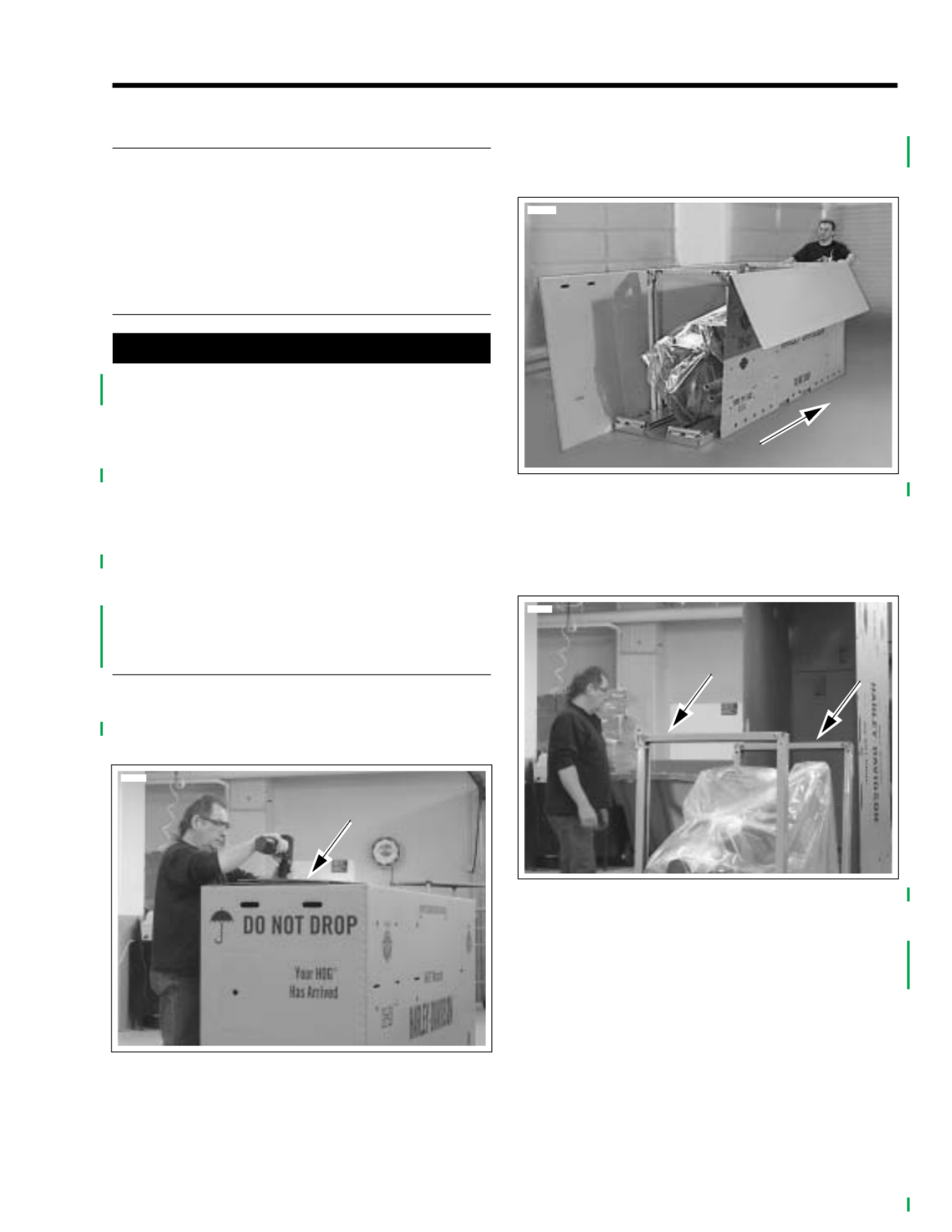
REMOVING CARDBOARD CARTON
1. See Figure 1-1. Use a T-20 bit and an electric or air pow-
dered drill/driver to remove all fasteners from cardboard
carton. Open top carton flaps.
2. See Figure 1-2. Using a box cutter, cut one end of the
cardboard carton. Slide carton away from pallet as
shown. Set carton aside for recycling.
3. See Figure 1-3. Remove both uprights (VRSC, FLST and
FLSTC crates have three uprights) by lifting upward. Set
uprights aside for recycling.
4. Open plastic bag enclosing motorcycle and push it down
off motorcycle. Remove protective tape and elastic pro-
tective netting, if present, from chrome and painted parts
of motorcycle.
Figure 1-1. Removing Screws
8796
Figure 1-2. Remove Cardboard Carton from Pallet.
Figure 1-3. Remove Uprights from Pallet
10426
8798
1
1-2 2005 PDI: All Models
NOTE
Always install/adjust handlebars before removing motorcycle
from pallet. See HANDLEBAR INSTALLATION–FLSTSC,
FLSTN AND FXDWG MODELS ADJUSTING HANDLE- and
BARS– ALL MODELS.
5. If uninstalled parts are in crate, verify your receipt of all
separate items by comparing with parts list in shipping
crate.
6. If vehicle has damage which appears to have occurred at
the factory, submit warranty claim form. Accurately
describe damage and cause. (e.g.–“Found nail in tire;
caused tire to go flat.”) Supply proper failure code(s).
1WARNING1WARNING
Do not alter or disable any device or system to circum-
vent local, state, or federal regulations. All safety and
environmental devices or systems must be left intact as
designed and built at the factory. Tampering with safety
and environmental devices or systems could result in
death or serious injury.
1WARNING1WARNING
The automatic-on headlamp feature provides increased
visibility for riders. Be sure headlamp is on at all times.
Low visibility of rider can result in death or serious
injury. (00030a).
1WARNING1WARNING
Some motorcycles are shipped with the hand brake lever
wrapped tight against the hand grip. Remove plastic
wrap and warning label (see ) and pump brakeFigure 1-4.
lever 3-4 times before moving motorcycle from pallet.
Failure to pump brake lever could result in an inoperable
front brake which could result in death or serious injury.
HANDLEBAR INSTALLATION–
FLSTSC, FLSTN AND FXDWG
MODELS
FLSTSC
After removing carton and protective plastic wrap:
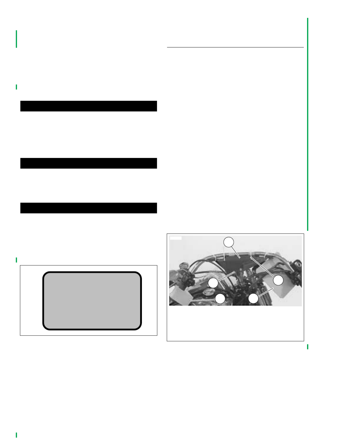
1. See Figure 1-5. While holding handlebars, remove the
riser bolts (2) securing handlebar shipping cradle (1) to
risers. Retain the four bolts, discard washers.
2. While holding the handlebar shipping cradle, cut cable
straps (3). Discard cradle and cable straps. Remove and
discard protective block (4) from left handlebar grip.
3. Route handlebar switch conduits between and behind
risers.
4. Position handlebar on top of risers, secure with riser
caps and riser bolts.
5. See and ADJUSTING HANDLEBARS– ALL MODELS
Figure 1-10. Following the Dyna Glide, Softail, XL 883,
XL 883L and XL 1200R Models procedure, adjust the
handlebars and tighten the riser bolts to 12-15 ft-lbs
(16.3-20.3 Nm) in the sequence given.
6. Push the four plastic wire retainers on the handlebar
switch conduits into the holes in the handlebars. Replace
any broken wire retainers.
7. Attach hand control and directional wire harnesses to
handlebar risers with cable straps (Part No. 10039).
8. Insert the clutch cable into the retaining clip on the left
frame downtube.
Figure 1-4. Warning Label
WARNING:
PUMP BRAKE LEVER
3-4 TIMES BEFORE
USING BRAKES
pd0171
Figure 1-5. FLSTSC
1. Handlebar shipping cradle
2. Riser bolt (4)
3. Cable strap (4)
4. Protective block
5. Protective pad
3
4
1
2
10612
5
2005 PDI: All Models 1-3
FLSTN
After removing carton and protective plastic wrap:
1. See Figure 1-6. Remove and discard cloth tie (3) secur-
ing handlebar.
2. Remove the riser bolts (2) and shipping clamp (1) from
handlebar risers. Retain the bolts. Remove and discard
protective block (4) from right handlebar grip.
3. Route handlebar switch conduits between and behind
risers.
4. Position handlebar on top of the risers and secure with
riser caps, and bolts removed in step 2.
5. See and ADJUSTING HANDLEBARS– ALL MODELS
Figure 1-10. Following the Dyna Glide, Softail, XL 883,
XL 883L and XL 1200R Models procedure, adjust the
handlebars and tighten the riser bolts to 12-15 ft-lbs
(16.3-20.3 Nm) in the sequence given.
6. Push the four plastic wire retainers on the handlebar
switch conduits into the holes in the handlebars. Replace
any broken wire retainers.
7. Insert the clutch cable into the retaining clip on the left
frame downtube.
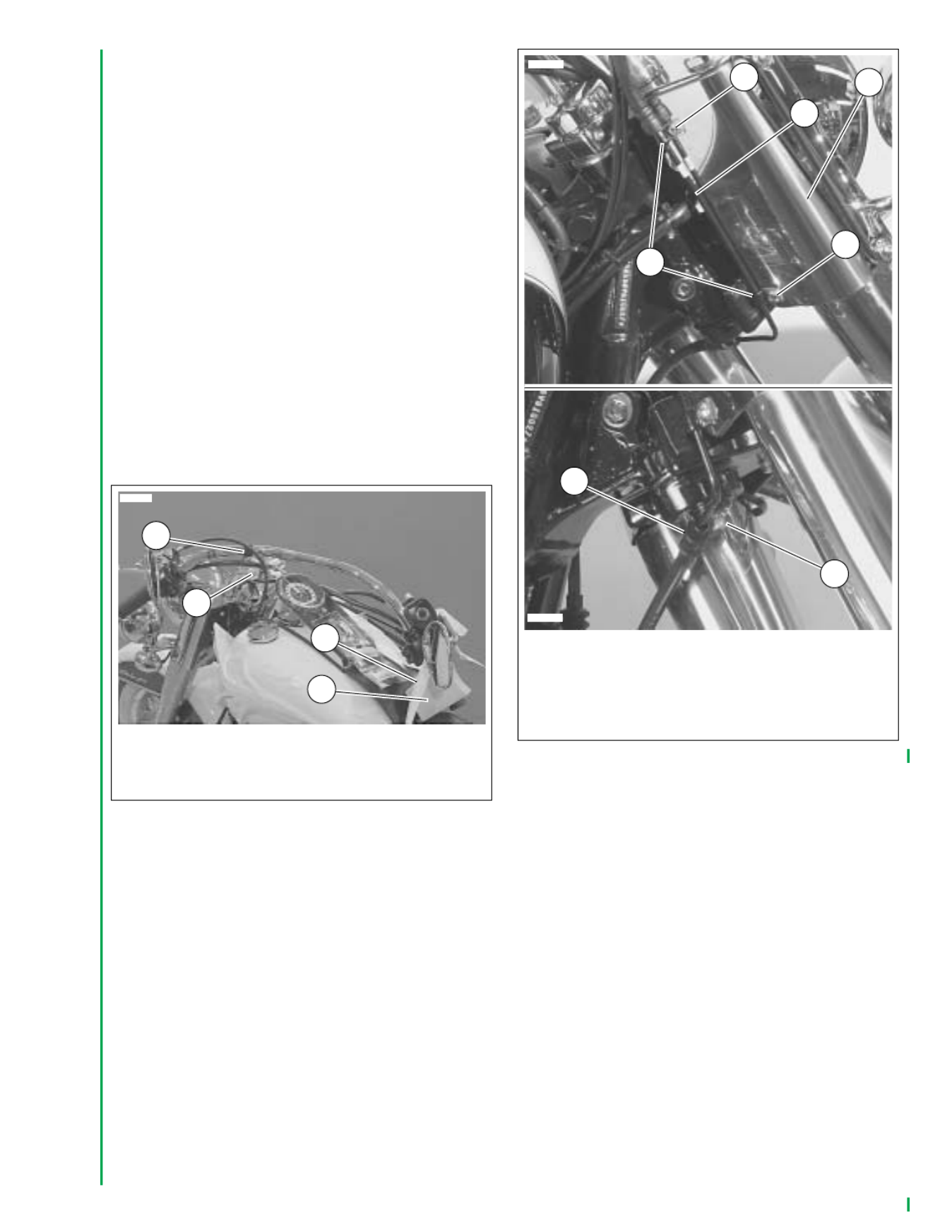
8. See Figure 1-7. Install front brake line (1) in clamps (2),
inboard of screws (3) and attach to fork stem cover (4).
Tighten screws to 30-50 in-lbs (3.4-5.7 Nm).
9. Install brake line in clamp (5) in underside of lower fork
clamp. Tighten screw (6) to 96-120 in-lbs (10.9-13.6
Nm).
Figure 1-6. FLSTN
1. Shipping clamp
2. Riser bolts
3. Cloth tie
4. Protective block
3
1
2
10613
4
Figure 1-7. Attaching Front Brake Line–FLSTN
1. Front brake line
2. Clamp (2)
3. Screw (2)
4. Fork stem cover
5. Clamp
6. Screw
1
6
2
10614
3
5
3
4
10615
1-4 2005 PDI: All Models
FXDWG
After removing carton and protective plastic wrap:
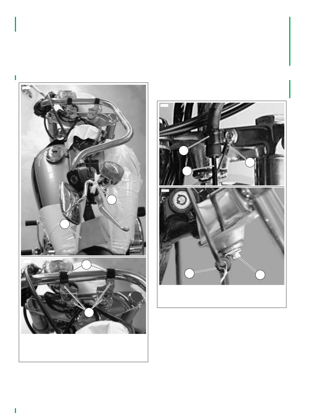
1. See Figure 1-8. Remove and discard cloth tie (1) secur-
ing handlebar.
2. Remove the four bolts (2) from the riser. Retain the four
bolts.
3. Reroute the left hand switch wire conduit from between
the riser to a position in front of the riser.
4. Retrieve riser caps from passenger backrest.
5. Position the handlebar on top of the risers and fasten the
riser caps in place using the bolts removed in step 2.
6. See and ADJUSTING HANDLEBARS– ALL MODELS
Figure 1-10. Following the Dyna Glide, Softail, XL 883,
XL 883L and XL 1200R Models procedure, adjust the
handlebars and tighten the riser bolts to 12-18 ft-lbs
(16.3-24.4 Nm) in the sequence given.
7. See Figure 1-9. Attach brake line (2) and ground wire (3)
on upper triple clamp with clamp (1). Position brake line
inboard from fastener. Tighten fastener to 30-60 in-lbs
(3.4-6.8 Nm).
Figure 1-8. FXDWG
1. Cloth tie
2. Riser bolts (4)
3. Shipping clamps
4. Protective block
1
4
3
2
6052
6053
Figure 1-9. FXDWG Brake Line and Ground Wire
3
2
1
1
2
6062
1. Clamp
2. Brake line
3. Ground wire
4. Clamp
5. Screw
45
6059

2005 PDI: All Models 1-5
CAUTION
See Figure 1-9. Attach brake line as shown before remov-
ing motorcycle from pallet. If brake line is not secured, it
could be pinched and damaged in front fork stop.
8. Attach brake line to bottom of steering stem with clamp
(4) and screw (5). Tighten to 96-120 in-lbs (10.9-13.6
Nm).
9. See Figure 1-8. Remove shipping clamps (3) from the
handlebar. Remove protective block (4) on throttle. Dis-
card shipping clamps and protective block.
10. Install clutch cable in clip on left downtube.
11. Install the plastic wire retainers on the handlebar switch
conduits and push into the holes in the handlebars.
Replace any broken wire retainers.
ADJUSTING HANDLEBARS–
ALL MODELS
General
CAUTION
Never adjust handlebars using excessive force. Doing so
may result in damage to handlebar or clamp.
NOTE
If handlebars are positioned for a rider of normal size, post-
pone adjustment until customer has checked their position. If
customer requests changing handlebar position, perform the
adjustment before delivering the motorcycle to the customer.
Always center the handlebar laterally (sideways) in the han-
dlebar clamps.
Before removing motorcycle from pallet, adjust handlebars
according to the following procedures:
Dyna Glide, Softail, XL 883, XL 883L and
XL 1200R Models
1. See Figure 1-10. Loosen four screws (3 and 4) of han-
dlebar upper clamp (6).
2. To be sure handlebars are properly centered, verify that
equal amounts of knurled areas on handlebar protrude
from outboard sides of upper handlebar clamp.
NOTE
On some models, knurled areas of handlebar will be com-
pletely hidden by upper handlebar clamp and will not be visi-
ble at all when handlebar is centered properly.
3. Raise handlebars to normal riding position and hold in
position.
4. Models with cast-in spacers (2) in upper clamp:
a. Tighten two rear screws (3) until cast-in spacers
contact handlebar lower clamps (1).
b. Dyna and Sportster models: tighten front screws (4)
to 12-18 ft-lbs (16.3-24.4 Nm). Softail models:
tighten front screws (4) to 12-15 ft-lbs (16.3-20.3
Nm).
c. Dyna and Sportster models: final tighten rear
screws to 12-18 ft-lbs (16.3-24.4 Nm). Softail mod-
els: final tighten rear screws to 12-15 ft-lbs (16.3-
20.3 Nm). Slight gap between upper and lower
clamps should exist at front.
5. Models without cast-in spacers in upper clamps:
a. Tighten all four screws finger-tight, maintaining
equal gaps between upper and lower clamps front to
back.
b. Dyna and Sportster models: tighten rear screws to
12-18 ft-lbs (16.3-24.4 Nm). Softail models: tighten
rear screws to 12-15 ft-lbs (16.3-20.3 Nm).
c. Dyna and Sportster models: tighten front screws to
12-18 ft-lbs (16.3-24.4 Nm). Softail models: tighten
front screws to 12-15 ft-lbs (16.3-20.3 Nm).
Figure 1-10. XL 883, XL 883L, XL 1200R,
Dyna Glide and Some Softail Models
pd0031d
1. Lower clamp (2)
2. Cast-in spacers (2)
3. Rear screw (2)
4. Front screw (2)
5. Instrument bracket (if equipped)
6. Upper clamp
3
2
4
1
5
6
Tighten
first
FRONT
1-6 2005 PDI: All Models
XL 883C and XL 1200C Models
1. See Figure 1-11. Loosen four screws (1, 2) of handlebar
upper clamp (3).
).
2. To be sure handlebars are properly centered, verify that
equal amounts of knurled areas on handlebar protrude
from outboard sides of upper handlebar clamp.
NOTE
On some models, knurled areas of handlebar will be com-
pletely hidden by upper handlebar clamp and will not be visi-
ble at all when handlebar is centered properly.
3. Raise handlebars to normal riding position; hold in posi-
tion. Tighten two front screws (1) to 12-18 ft-lbs (16.3-
24.4 Nm).
4. Tighten rear screws (2) to 12-18 ft-lbs (16.3-24.4 Nm).
FLHT, FLHTC, FLHTCU and FLHTP
1. Remove ignition switch knob and inner fairing cap
according to appropriate Touring Models Service Manual
instructions.
2. See Figure 1-12. Loosen two rear screws (3) of handle-
bar upper clamps (2).
3. If there is a gap between either handlebar lower clamp
(1) and upper clamp at front, tighten front screw (4) only
enough to close gap. If handlebars do not move up and
down freely, loosen rear screws until they do.
4. Raise handlebars to normal riding position. To be sure
handlebars are properly centered, verify that equal
amounts of knurled areas on handlebar protrude from
outboard sides of both handlebar clamps.
5. Tighten rear screws to 12-16 ft-lbs (16.3-21.7 Nm). Slight
gap should exist between upper and lower clamps at
rear.
6. Check torque on front handlebar clamp screws. Tighten
screws to 12-16 ft-lbs (16.3-21.7 Nm).
7. Reinstall inner fairing cap and ignition switch knob
according to appropriate Touring Models Service Manual
instructions.
Figure 1-11. XL 1200C, XL 883C Custom Models
1. Front screw (2)
2. Rear screw (2)
3. Upper clamp
4. Lower clamp
pd0031f
2
1
4
3
FRONT
Tighten
first
Figure 1-12. FLHT/C/U and FLHTP Models
1. Lower clamp (2)
2. Upper clamp (2)
3. Rear screw (2)
4. Front screw (2)
FRONT
pd0021a
3
2
1
4
2005 PDI: All Models 1-7
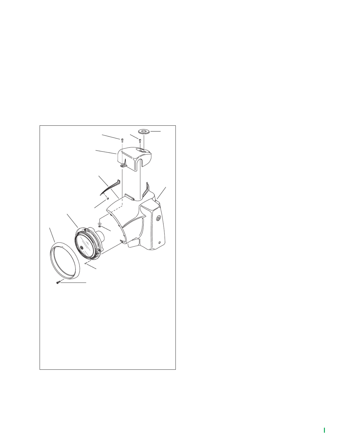
FLHR/C/S/I Road King, FLHP, FLHPE
1. See Figure 1-13. Remove screw (12) securing chrome
ring (11) to headlamp nacelle (7). Remove chrome ring.
2. Remove eight screws (10) securing headlamp assembly
(9). Squeeze two external tabs (if present) to remove
wire connector at back of headlamp bulb. Remove head-
lamp assembly from vehicle.
3. Remove nut (1) (inside nacelle) securing nacelle trim (2).
4. On Police models, disconnect tachometer lead.
5. Remove nacelle trim. Loosen (but do not remove) front
handlebar clamp shroud screw (3), nut and washer (4).
6. Gently pry off fork lock plate (5) at rear of handlebar
clamp shroud (8). Remove two screws (6) beneath lock
plate.
7. Loosen four acorn nuts securing nacelle halves to fork
studs. Spread nacelle halves slightly and remove handle-
bar clamp shroud.
8. Adjust handlebars following steps 2. 6. - of the FLHT,
FLHTC, FLHTCU and FLHTP procedure given on previ-
ous page.
9. Reinstall handlebar clamp shroud. Tighten acorn nuts
securing nacelle halves to fork studs to 72-108 in-lbs
(8.1-12.2 Nm).
10. Install two screws (6) to handlebar clamp shroud and
tighten to 10-20 in-lbs (1.1-2.3 Nm). Gently press fork
lock plate (5) into place on handlebar clamp shroud.
11. Tighten front handlebar clamp shroud nut (4) to 10-20
in-
lbs (1.1-2.3 Nm).
12. On police models, connect tachometer lead.
13. Install nacelle trim (2). Install nut (1) (inside nacelle) secur-
ing nacelle trim. Tighten to 15-20
in-lbs (1.7-2.3 Nm).
14. Connect wire connector to socket on back of headlamp
bulb. Install and secure headlamp assembly to nacelle
with eight fasteners.
15. Secure chrome ring (11) to headlamp nacelle with screw
(12).
NOTE
Check clearance between windshield and clutch cable and
handlebar position prior to completing assembly of vehicle.
Figure 1-13. FLHR/C, FLHP, FLHPE Models
5
pd0226 3
2
1
4
7
1. Nut
2. Nacelle trim
3. Front handlebar clamp shroud screw
4. Nut and washer
5. Fork lock plate
6. Screw (2)
7. Nacelle
8. Handlebar clamp shroud
9. Headlamp assembly
10. Screw (8)
11. Chrome headlamp ring
12. Screw
9
10
12
11
6
8
1-8 2005 PDI: All Models
FLTR Road Glide
1. See Figure 1-14. Remove two T25 TORX screws at sides
of instrument bezel.
2. Carefully push tab at rear of instrument bezel from slot
above ignition switch. Gently raise free side of bezel until
tabs at front of instrument nacelle disengage from slot at
front of bezel (concealed behind decorative adhesive
strip). Move instrument bezel to one side.
3. See Figure 1-15. Loosen two front screws securing han-
dlebar upper clamps (Instrument bezel has been
removed in drawing for clarity).
4. Raise handlebars to normal riding position. Tighten front
handlebar clamp screws to 12-16 ft-lbs (16.3-21.7 Nm).
5. Verify that left and right sides of instrument nacelle are
properly mated. Pins on left side of nacelle must fully
engage holes on right.
6. Insert tab at rear of bezel into slot of instrument nacelle
just above ignition switch. Holding left and right sides of
nacelle together, place bezel over instrument nacelle
flange. when properly mated, tabs at front of instrument
nacelle engage lip in slot at front of bezel behind decora-
tive adhesive strip.
NOTE
If tabs do not properly engage slot at front of bezel, a loose fit
will result. Remove decorative adhesive strip by gently prying
up outer edges. Using a flat bladed screwdriver, carefully
raise tabs so they engage lip in slot. If damaged, install
new
decorative adhesive strip.
Figure 1-14. FLTR Models-Instrument Bezel Screws
Figure 1-15. FLTR Models-Front Handlebar Clamp Screws
0
20
30
70
80
40 50
60
10
RPM x100
0
10
30
20
50
40
110
120
60 70 80
90
100
MPH
H
A
R
L
E
Y
-
D
A
V
I
D
S
O
N
M
O
T
O
R
C
O
M
P
A
N
Y
CERTIFIE D
SE SC
HARLEY-DAVI DSON MOTOR COMPANY INC.
R
1 PRO
2 HRS
3 MIN
4
EJECT
LO/DX
POWER
®
H
A
R
L
E
Y
-
D
A
V
I
D
S
O
N
M
O
T
O
R
C
O
M
P
A
N
Y
pd0201
pd0195
2005 PDI: All Models 1-9
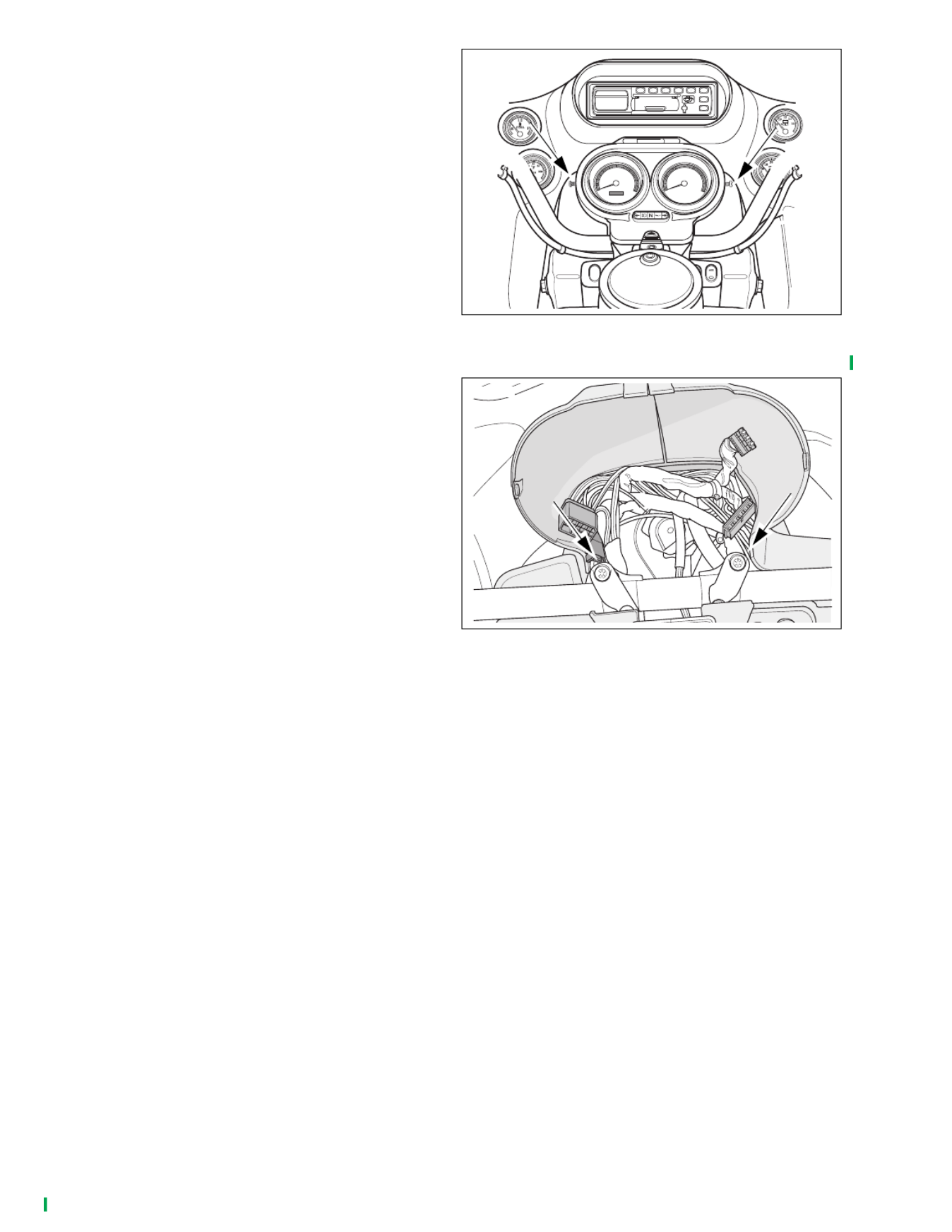
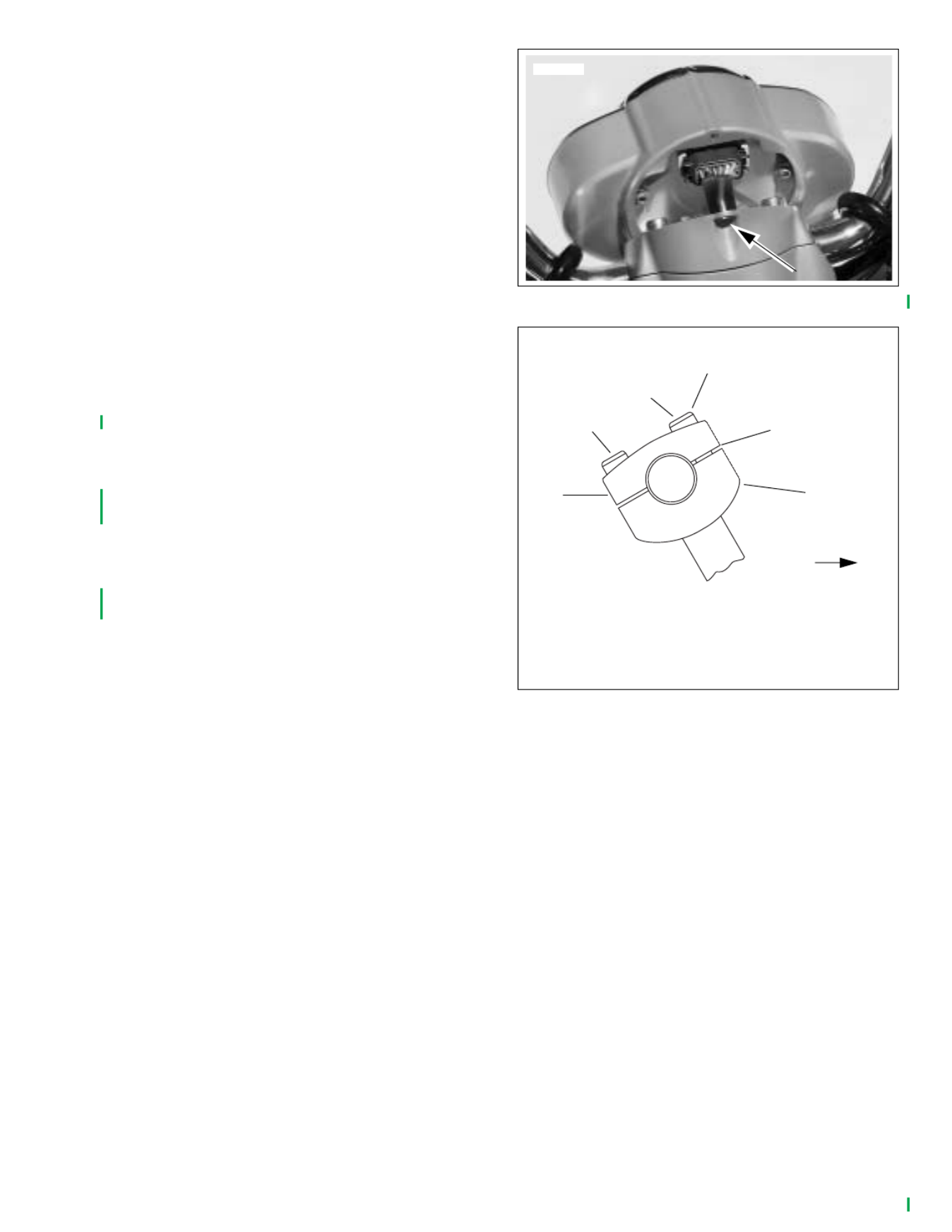
VRSCB
NOTE
To gain access to the handlebar adjusting screws, the follow-
ing steps will be necessary:
1. Remove Maxi-Fuse.
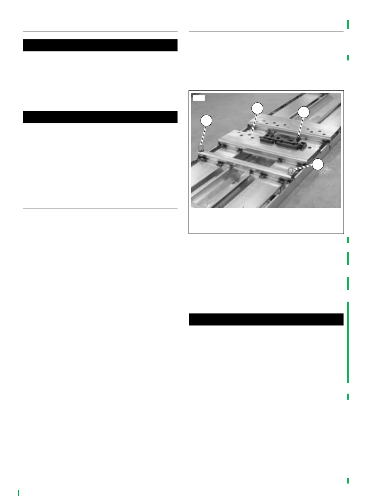
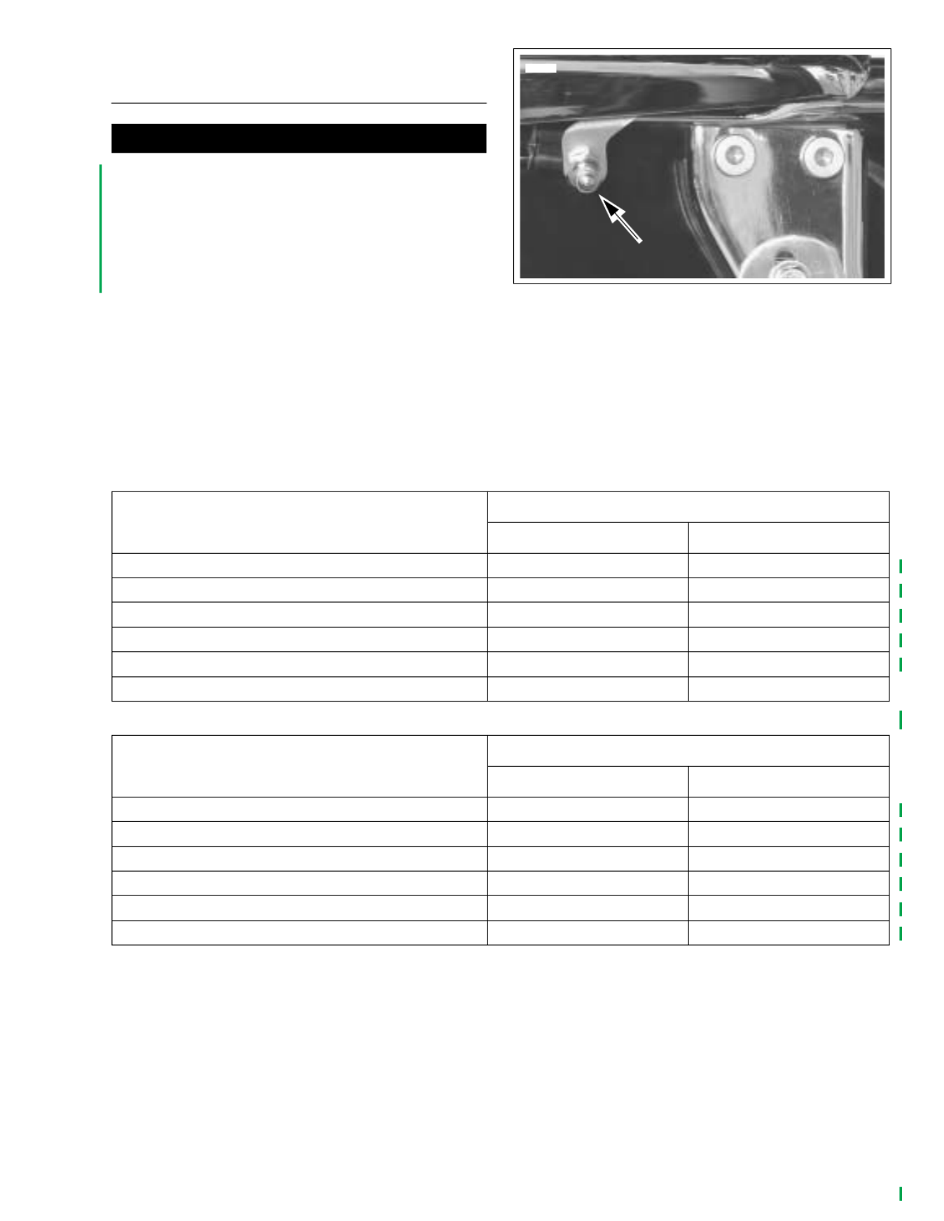
2. See Figure 1-16. Remove instrument cluster screw from
location shown and pivot instrument cluster away from
handlebars.
3. Remove wiring harness connector and remove screw on
bottom side of instrument cluster.
4. Remove instrument cluster.
5. To be sure handlebars are properly centered, verify that
equal amounts of knurled areas on handlebar protrude
from outboard sides of upper handlebar clamp.
NOTE
On some models, knurled areas of handlebar will be com-
pletely hidden by upper handlebar clamp and will not be visi-
ble at all when handlebar is centered properly.
6. See Figure 1-17. Raise handlebars to normal riding posi-
tion; hold in position. Tighten two front screws (4) until
cast-in spacers (2) of upper clamp contact handlebar
lower clamp (1).
7. Tighten rear screws (3) to 16-20 Nm (12-15 ft-lbs).
8. Final tighten front screws (4) to 16-20 Nm (12-15 ft-lbs).
Slight gap between upper and lower clamps should exist
at rear.
9. Install instrument cluster.
10. Insert instrument cluster screw and tighten to 2.2-2.8 Nm
(20-24 in-lbs).
11. Install Maxi-Fuse.
Figure 1-16. Instrument Cluster Mounting Screw Location
Figure 1-17. VRSCB Models
10059
1. Lower clamp
2. Cast-in spacers (2)
3. Rear screw (2)
4. Front screw (2)
5. Upper clamp
pd0021b
32
5
Tighten
first
FRONT
1
4
1-10 2005 PDI: All Models
REMOVING VEHICLE FROM PALLET
All Models
1WARNING1WARNING
Always have someone steady motorcycle while each
strap is being removed to prevent tipping. Motorcycle
front suspension is secured in a compressed state by
two nylon straps. Releasing strap tension on one side of
motorcycle could result in the front of motorcycle rising
and leaning abruptly to opposite side, which could result
in death or serious injury.
1WARNING1WARNING
Always wear safety glasses and gloves and keep
bystanders at a safe distance when uncrating the motor-
cycle. When released, each strap will unwind rapidly from
its ratchet lever, and end of strap could recoil in an out-
ward direction, which could result in death or serious
injury.
1. Remove crating straps.
a. Have an assistant hold the motorcycle’s handlebars.
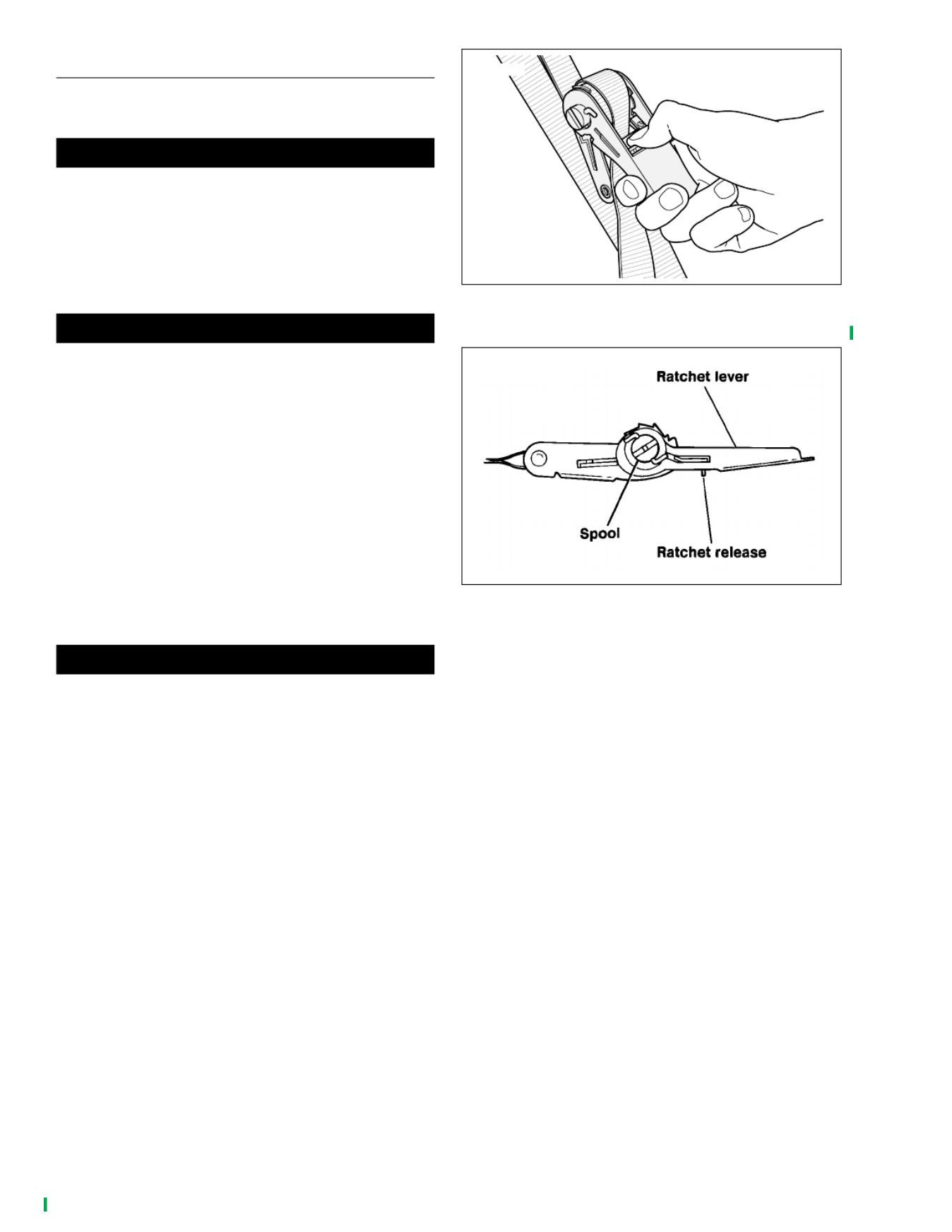
b. See Figure 1-18. Start with the right side crating
strap. Depress (in opposite direction of spool) and
hold down the spring-loaded ratchet release.
c. See Figure 1-19. Swing open the ratchet lever to the
release position; tensioned nylon strap will rapidly
unwind. remove strap and any protective padding
from pallet.
1CAUTION
On VRSC models, a third strap is located at the left rear.
After this rear strap is removed, unscrew the rear eye-
bolt to prevent tripping and falling over it. Falling could
result in minor or moderate injury. Also, if eyebolt is not
removed, the left radiator trim or other low-left-side com-
ponents could be damaged when motorcycle is rolled off
pallet.
Figure 1-18. Opening Ratchet Lever
Figure 1-19. Strap Ratchet Lever (Release Position)
b0458xpx
pd0051
2005 PDI: All Models 1-11
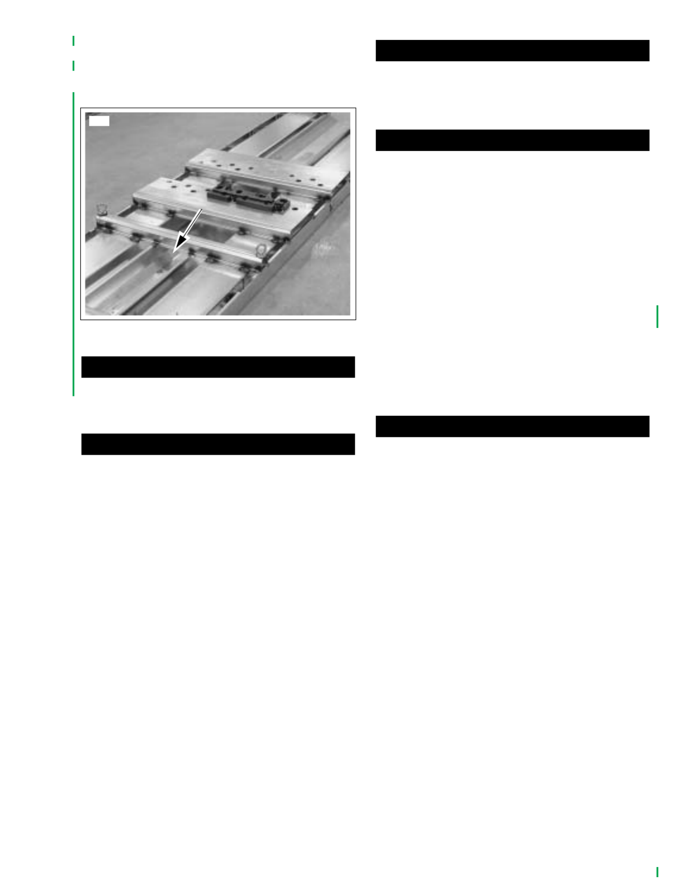
2. See Figure 1-20. Place a 2x4 in. (50.8x101.6 mm) board
between steel cross braces (see arrow) behind front tire
to aid rolling motorcycle rearward off pallet.
3. Carefully roll vehicle off pallet.
1WARNING1WARNING
Always park motorcycle on a level, firm surface. An
unbalanced motorcycle can fall over which could result
in death or serious injury. (00039a)
1WARNING1WARNING
The jiffy stand locks when placed in the full forward
(down) position with vehicle weight on it. If the jiffy stand
is not in the full forward (down) position with vehicle
weight on it, the vehicle can fall over which could cause
death or serious injury. (00006a)
1WARNING1WARNING
Be sure jiffy stand is fully retracted before riding. If jiffy
stand is not fully retracted, it can contact the road sur-
face causing loss of vehicle control, which could result
in death or serious injury. (00007a)
1WARNING1WARNING
Improperly aligned or adjusted handlebars can contact
fuel tank when turned to left or right fork stops. Contact
with fuel tank while riding can cause loss of vehicle con-
trol resulting in death or serious injury.
4. Slowly turn handlebars back and forth to the full right and
full left fork stops to be sure handlebars (and/or turn sig-
nals on some models) do not contact fuel tank. Also be
sure cables and wiring are not pinched or stretched as
handlebars are turned back and forth.
a. If contact between handlebars and fuel tank occurs
and handlebars are properly centered, perform han-
dlebar adjustment again (see ADJUSTING HAN-
DLEBARS– ALL MODELS), raising handlebars as
necessary to clear fuel tank.
b. On models with turn signals mounted on handlebar
control housings, if turn signal contacts fuel tank,
adjust turn signals and/or handlebar control hous-
ings according to appropriate Service Manual
instructions.
1WARNING1WARNING
Throttle control must operate freely without binding.
Irregular or sticking throttle cables could cause a loss of
control, leading to an accident which could result in
death or serious injury.
Figure 1-20. Vehicle Pallet
7770
1-12 2005 PDI: All Models
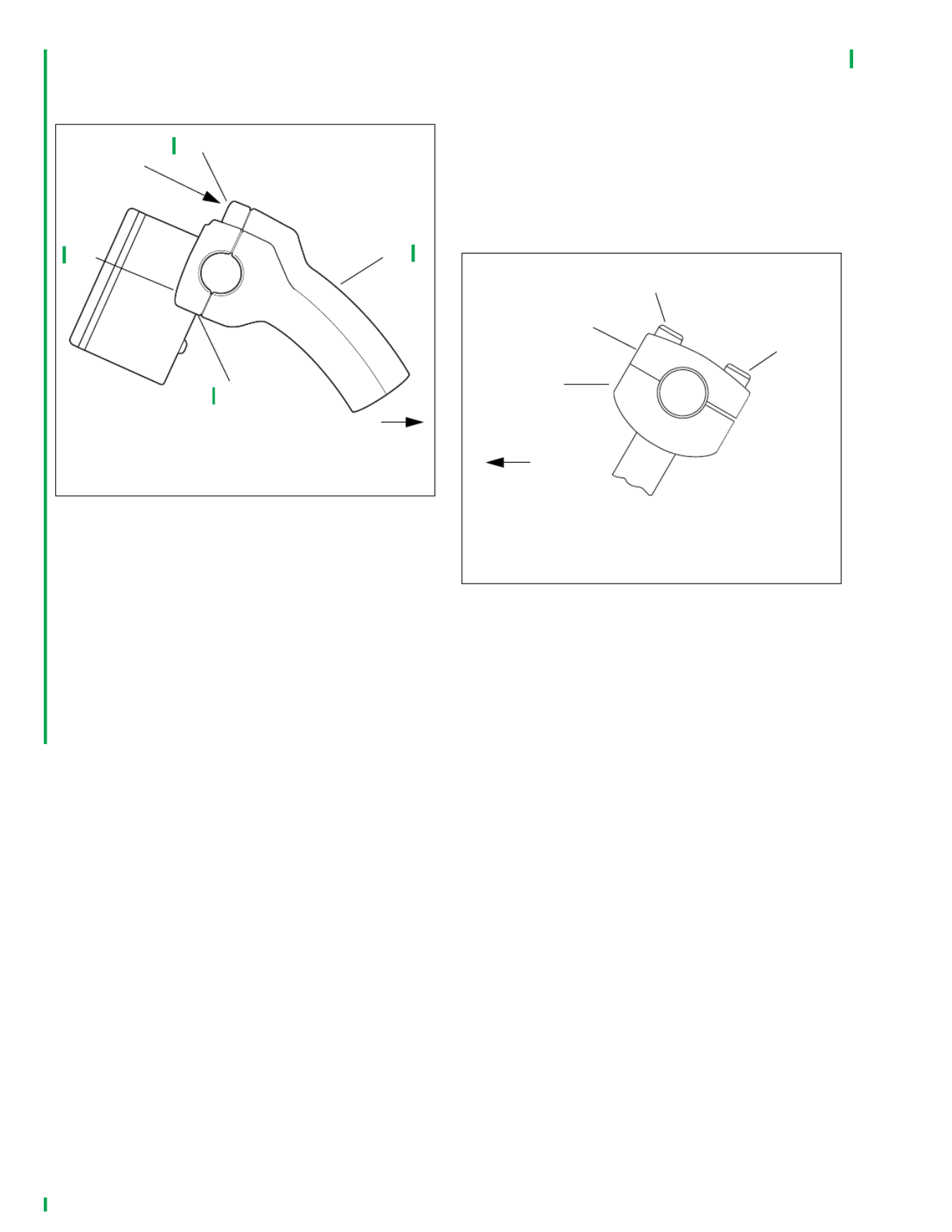
CLUTCH HAND LEVER
NOTE
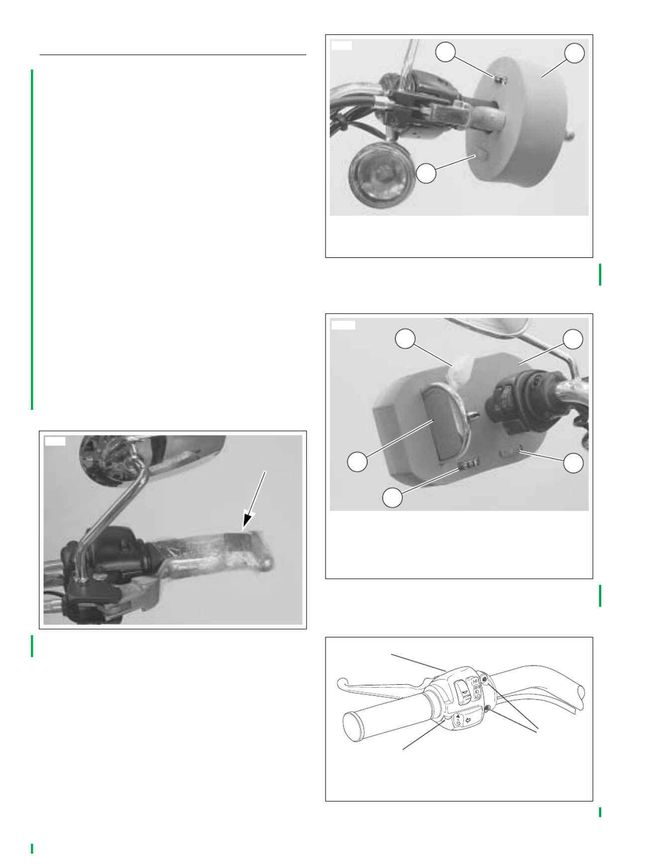
●See Figure 1-21. All Dyna models have Maxi-Fuse
wrapped in plastic wrapping around clutch hand lever
and left handlebar grip.
●See See Figure 1-22. Figure 1-23. All Sportster models
have Maxi-Fuse and headlamp snap cap fitted into pro-
tective foam on clutch hand lever and left handlebar grip.
Save snap cap for installation after headlamp has been
adjusted. Sportster model XL 883L also has righthand
mirror fitted into protective foam.
1. Remove plastic wrapping or protective foam from clutch
hand lever and left handlebar grip.
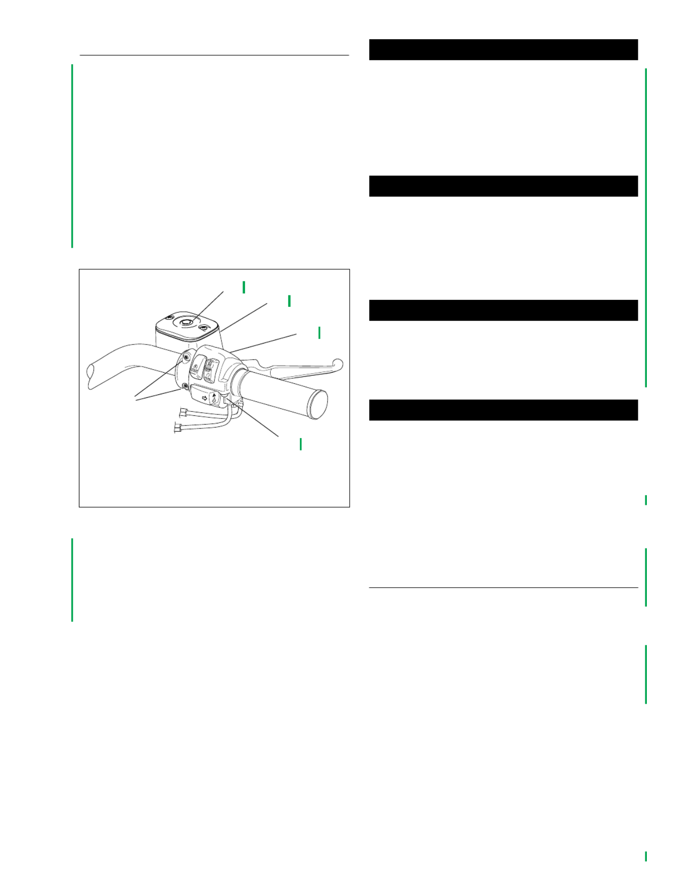
2. If handlebar controls need to be adjusted, perform the
following procedure.
a. See Figure 1-24. Loosen, but do not remove, clutch
control housing clamp screws (1) and handlebar
switch housing clamp screws (2).
b. Rotate clutch control housing and handlebar switch
housing as necessary for correct position and rider
comfort.
c. Beginning with the top screw, tighten clutch control
housing clamp screws. All Sportster models: tighten
to 108-132 (12.2-14.9 Nm). All other models:in-lbs
tighten to 60-80 in-lbs (6.8-9.0 Nm).
d. Tighten handlebar switch housing clamp screws to
35-45 in-lbs (4.0-5.1 Nm).
Figure 1-21. Location of Maxi-Fuse on Clutch
Hand Lever–Dyna Models
10616
Figure 1-22. Location of Maxi-Fuse and Snap Cap on
Clutch Hand Lever–All Sportster Models Except XL 883L
Figure 1-23. Location of Maxi-Fuse and Snap Cap on
Clutch Hand Lever–Sportster XL 883L
Figure 1-24. Left Hand Controls (Typical)
10702
1. Clutch lever restraining foam
2. Headlamp snap cap (XL 883 and XL 1200R only)
3. 30-amp Maxi-Fuse
1
2
3
1. Clutch lever restraining foam
2. Headlamp snap cap
3. 30-amp Maxi-Fuse
4. Mirror
5. Package of mirror mounting hardware
10703
1
2
3
4
5
pd0217
1. Clutch control housing clamp screw (2)
2. Handlebar switch housing clamp screw (2)
2
1
2
2005 PDI: All Models 1-13
FRONT BRAKE HAND LEVER
If handlebar controls need to be adjusted, perform the follow-
ing procedure.
1. See Figure 1-25. Loosen, but do not remove, front brake
master cylinder clamp screws (1) and handlebar switch
housing clamp screws (2).
2. Rotate master cylinder housing and handlebar switch
housing as necessary for correct position and rider com-
fort.
3. Beginning with the top screw, tighten front brake master
cylinder clamp screws. All Sportster models: tighten to
108-132 in-lbs (12.2-14.9 Nm). All other models: tighten
to 60-80 in-lbs (6.8-9.0 Nm).
4. Tighten handlebar switch housing clamp screws to 35-45
in-lbs (4.0-5.1 Nm).
IMPORTANT NOTE
All Touring model motorcycles use D.O.T. 4 HYDRAULIC
BRAKE FLUID (Part No. 99953-99A). All Dyna, Softail,
VRSC and Sportster models use D.O.T 5 SILICONE
HYDRAULIC BRAKE FLUID (Part No. 99902-77: 12 oz.,
99901-77: 1 gal.). If it is necessary to top off the brake
fluid in the reservoir, make sure you add the correct type.
1CAUTION
Direct contact of D.O.T. 5 brake fluid with eyes can cause
eye irritation, swelling, and redness. Avoid eye contact.
In case of eye contact, flush with large amounts of water
and get medical attention. Swallowing large amounts of
D.O.T. 5 brake fluid can cause digestive discomfort. If
swallowed, obtain medical attention. Use in well venti-
lated area. KEEP OUT OF REACH OF CHILDREN.
(00144a)
1CAUTION
Direct contact of D.O.T. 4 brake fluid with eyes can cause
irritation. Avoid eye contact. In case of eye contact flush
with large amounts of water and get medical attention.
Swallowing large amounts of D.O.T. 4 brake fluid can
cause digestive discomfort. If swallowed, obtain medical
attention. Use in well ventilated area. KEEP OUT OF
REACH OF CHILDREN. (00240a)
CAUTION
D.O.T. 4 brake fluid will damage painted and molded-in
color surfaces it comes in contact with. Always use cau-
tion and protect surfaces from spills whenever brake
work is performed. Failure to comply can result in cos-
metic damage. (00239a)
CAUTION
Cover handlebar switches with a shop towel before add-
ing brake fluid to front master cylinder reservoir. Spilling
brake fluid on handlebar switches may render them inop-
erative.
NOTE
AUSTRALIAN MODELS ONLY: Measure from tip of clutch
lever to tip of brake lever. Measurement must not exceed 1
meter in length. If it does, re-adjust accordingly.
FRONT BRAKE MASTER CYLINDER
RESERVOIR
See Figure 1-25. View reservoir sightglass (3 or 4) and verify
fluid presence. Sightglass should appear dark if fluid is
present. If sightglass is not dark, add brake fluid. See Service
Manual. Use only D.O.T. 5 SILICONE HYDRAULIC BRAKE
FLUID (Part No. 99902-77: 12 oz., 99901-77: 1 gal.). for all
Dyna, Softail, VRSC and Sportster models. Use only D.O.T. 4
HYDRAULIC BRAKE FLUID (Part No. 99953-99A) for all
Touring models. Wash all residue of D.O.T. 4 brake fluid spills
off vehicle with water.
Figure 1-25. Right Hand Controls (Typical)
pd0218
1. Front brake master cylinder clamp screw (2)
2. Handlebar switch housing clamp screw (2)
3. Reservoir sightglass (XL models)
4. Reservoir sightglass (all models except XL)
3
4
2
1
2
1-14 2005 PDI: All Models
VEHICLE CLEANUP
1WARNING1WARNING
Do not let the brakes, engine, mufflers or air cleaner get
wet when washing your motorcycle. Allowing these com-
ponents to get too wet can adversely affect their perfor-
mance, which could result in death or serious injury.
Start engine immediately after washing, and make sure
brakes and engine are operating properly before riding in
traffic. (00078b)
CAUTION
Avoid spraying water directly on handlebar switches. Wet
handlebar switches may be inoperative.
Remove protective shipping tape from motorcycle. Wash
entire motorcycle before beginning actual predelivery inspec-
tion. If vehicle is equipped with frame downtube reflectors,
remove any plastic cable straps wrapped around reflectors
(cable straps are used during assembly at factory for retain-
ing reflectors to downtubes while reflector adhesive cures).
COSMETIC QUALITY
Paint Finish Inspection and Repair
Under good lighting conditions, examine all painted parts for
any damage or irregularities in the paint finish. To aid the
dealer network in addressing quality concerns, Harley-David-
son Motor Company has developed a zoning and criteria pro-
tocol, which enables us to exceed customer’s expectations. If
you discover any condition requiring repair, use Paint Repair
Kit (Part No. HD-39994); available through Kent-Moore, at the
following address, to correct the condition.
Kent-Moore
28635 Mound Rd
Warren, Michigan 48092-3499
(phone) 1-800-345-2233
Instructions covering painted part repair are included with the
Paint repair Kit. Additional paint repair information is available
from Harley-Davidson on the PHD training videotape No. 136.
Additional cosmetic quality information is available in the Har-
ley-Davidson Cosmetic Booklet (Part No. HD-99514-05) and
on-line Cosmetic Training located on HDU On-line.
RETURNING STEEL PALLETS
NOTE
International Dealers/Distributors should check with their H-D
office to determine whether or not to return pallets.
1. See Figure 1-26. Remove and discard plastic motor shim
(1).
2. Turn eye-bolts (2) so they are parallel with sides of pallet.
This will allow stacking pallets for shipment.
NOTE
On VRSC pallets place eye-bolt from rear in enclosed area
(3) of pallet.
3. Place hold-down straps you are returning to factory in
enclosed area (3) of pallets.
CAUTION
Do not mix 29 in. (736.6 mm) width pallets with 43 in.
(1.09 m) width pallets on the same 7-pallet stack. Mixing
pallets of different width could result in an unstable bun-
dle and pallet damage.
4. Stack seven pallets keeping all eye-bolts on same end.
5. Band pallets by threading hold-down straps through both
end cross members of top and bottom pallets. (If neces-
sary connect two straps together.)
6. Tighten straps to secure pallet bundles.
7. Call, Fax, E-mail or use www.h-dnet.com to arrange
pallet return to Harley-Davidson.
Figure 1-26. Vehicle Pallet
1. Plastic motor shim
2. Eye-bolts
3. Enclosed area
7770
2
31
2
2005 PDI: All Models 1-15
MAINTENANCE-FREE BATTERIES
All models are equipped with maintenance-free batteries that
are permanently sealed, valve-regulated, lead/calcium and
sulfuric acid electrolyte batteries. The electrolyte is immobi-
lized in a glass fibre separator. Therefore, the batteries are
identified as “Type AGM” which is the acronym for Absorbed
Glass Mat technology. The batteries are shipped pre-charged
and ready to be put into service. Do not attempt to open
these batteries for any reason. These batteries do not have a
vent tube. Perform Voltmeter Test to check if battery requires
charging.
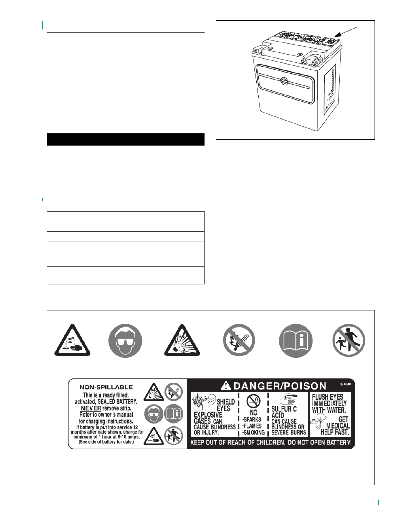
1WARNING1WARNING
Batteries contain sulfuric acid, which could cause severe
burns to eyes and skin. Wear a protective face shield,
rubberized gloves and protective clothing when working
with batteries. KEEP BATTERIES AWAY FROM CHIL-
DREN. (00063a)
Table 1-1. Battery Electrolyte Antidote
PHYSICAL
LOCATION PROCEDURE
External Flush with water
Internal Drink large quantities of milk or water,
followed by milk of magnesia, vegetable oil
or beaten eggs. Call doctor immediately
Eyes Flush with water, get immediate
medical attention.
Figure 1-27. Warning Label
M A D E I N U S A
H
AR
L
E
Y-D A
VID S
O
N
M
IL W
AU
KE
E
,
W I
5 32
0
1
M
A
D
E
IN
U.S
.
A.
WARR A
NTY AN D ADJU S
TMENT POLIC Y
Th
is ba tte
ry will be rep
lace d with out ch a
rge
if
fo
un d
to
b
e
de
fe
ct
iv
e i n
m
at
e
ri a
l
s o
r
w
o
rk
man
sh
ip
1
2
m
on
th
s fr
om
da
te
o
f
ve
hi
cl e p
u
rc
ha
se
o
r
6 m o
n
th
s
fro
m
d
at
e
o
f o
v
e
r
-th
e-
co
u
n
t
er
p
ur
c
h
as
e. A
fte
r
6
mo
n
th s,
b
u
t
w
ith
in
th
e
1 2 m
on
th
s
of
th
e
over
-th e- coun ter purchas e, th e bat tery w
ill
b
e
re
p
l
ac
ed
a
nd
t
he
p
ur
c
h
a
se r c
h
a
r
ge
d
on ly f or t
h e peri od of own ersh i p bas ed on
th
e
re g
ula
r
pr
ic
e
a
t
th
e
t
im
e
o f r
et
ur
n
pr
or
at ed
v
e
r
th
e
nu
m
b
er
of
m o
nt
h
s
o
f
warran ty. This war
ranty i s not tran sf erabl e
a
n
d i
s
vo
id
e
d
b
y
t
h
e
us
e
of
re ju
ve
na
to
rs
,
im
p
ro pe
r
el
e
c
tro
ly
te
, n
eg le
ct
o r a
b
us
e.
P
AR
T
N
O
.
1234567890
JA FE M A AP MY JU JY AU SE OC NO D E
f1730x8x
Figure 1-28. Battery Warning Label
1. Contents are corrosive
2. Wear safety glasses
3. Contents are explosive
4. Keep flames away
5. Read instructions
6. Keep away from children
1 2 3 4 5 6
f2180x3x
1-16 2005 PDI: All Models
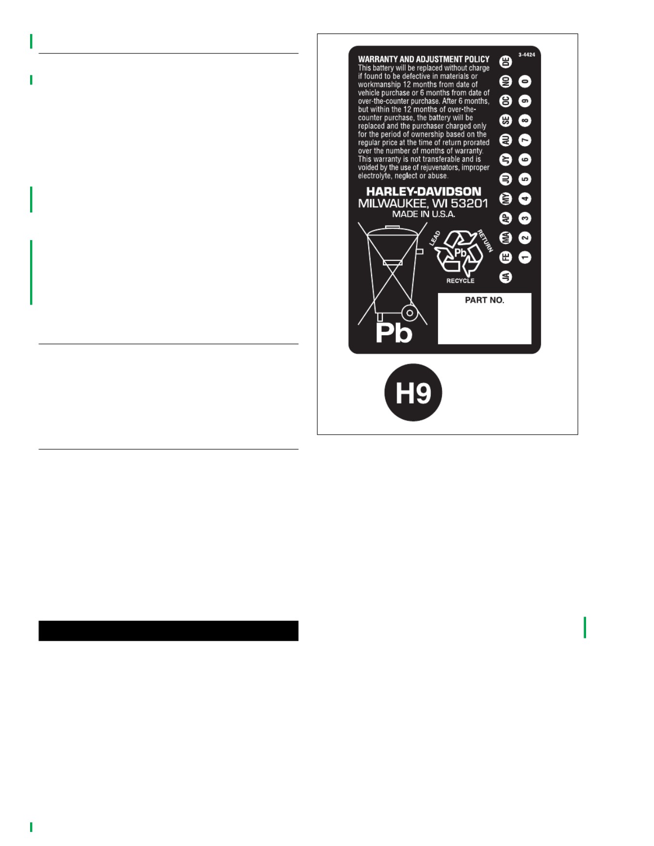
DATE OF MANUFACTURE CODE
See Figure 1-29. The battery date code sticker has a number
and two letters. The number signifies the year the battery was
manufactured.
9 – 1999
0 – 2000
1 – 2001
2 – 2002
3 – 2003
4 – 2004
5 – 2005
The letters signify the month the battery was activated.
JA–January MY–May SE–September
FE–February JU–June OC–October
MA–March JY–July NO–November
AP–April AU–August DE–December
VOLTMETER TEST
Refer to Ta ble 1-2. The voltmeter test provides a general indi-
cator of battery condition. Check the voltage of the battery to
make sure it is 12.6 V. If the open circuit (disconnected) volt-
age reading is below 12.6 V, charge battery and recheck volt-
age after battery has sat 1-2 hours.
CHARGING BATTERY
NOTE
The sealed AGM batteries do not need to be removed for
charging. Only remove battery if cable connection or marking
the Warranty Tag requires it.
1. Connect the red battery charger lead to the positive ter-
minal of the battery and the black charger lead to the
negative terminal.
2. Refer to Ta ble 1-2. Charge battery for time specified in
Tabl e 1-2.
3. If battery gets hot, over 110˚F (44˚C) (warm to the
touch), discontinue charging and let battery cool down.
1WARNING1WARNING
Unplug or turn OFF battery charger before disconnecting
charger cables from battery. Disconnecting clamps with
charger ON can cause a spark and battery explosion,
which could result in death or serious injury. (00067a)
4. After the battery is fully charged, disconnect the black
battery charger lead to the negative (–) terminal of the
battery.
5. Disconnect the red battery charger lead to the positive
(+) terminal of the battery.
6. See Figure 1-29. Mark the date on the battery warranty
tag by removing the applicable month and year. If the
date is after the 15th day of the month, advance the date
to the next month. For example, if the battery is put in
use July 22, punch out the month of August, which is
abbreviated on the tag as “AU.” To determine the correct
number to punch out for the year, just reference the last
digit of the current year. Therefore, the number “5” is
punched to signify the year 2005.
Figure 1-29. Battery Warranty Tag/Date Code Sticker
Battery date of
manufacture code
f1742x8x

2005 PDI: All Models 1-17
NOTE
The figures listed above assume that the battery is charging
at room temperature. If warmer than room temperature, use a
slightly shorter charging time. If colder, use a slightly longer
charging time.
NOTE
The use of constant current chargers to charge sealed main-
tenance-free batteries is not recommended. Any overcharge
will cause dry-out and premature battery failure. If a constant
current charger is the only type available, do not exceed the
charge times listed above and do not continue charging the
battery if it gets hot. When charging, never exceed 15 volts for
more than 30 minutes.
Table 1-2. Battery Charging Rates/Times (Approximate)
BATTERY
AMP HOUR
STATE OF CHARGE 3 AMP
CHARGER
6 AMP
CHARGER
10 AMP
CHARGER
20 AMP
CHARGER
VOLTAGE % OF CHARGE
VRSC,
SPORTSTER
12
12.8 100% - - - -
12.6 75% 70 minutes 34 minutes 20 minutes 10 minutes
12.3 50% 2 hours,
20 minutes 70 minutes 40 minutes 20 minutes
12.0 25% 3 hours,
20 minutes
1 hour,
40 minutes 1 hour 30 minutes
11.8 0% 4 hours,
30 minutes
2 hours,
14 minutes
1 hour,
20 minutes 40 minutes
DYNA,
SOFTAIL
18
12.8 100% - - - -
12.6 75% 1.75 hours 50 minutes 30 minutes 15 minutes
12.3 50% 3.5 hours 1.75 hours 1 hour 30 minutes
12.0 25% 5 hours 2.5 hours 1.5 hours 45 minutes
11.8 0% 6 hours,
40 minutes
3 hours,
20 minutes 2 hours 1 hour
TOURING
28
12.8 V 100% - - - -
12.6 V 75% 2.5 hours 1.25 hours 45 minutes 25 minutes
12.3 V 50% 5 hours 2.5 hours 1.5 hours 50 minutes
12.0 V 25% 7.5 hours 3.75 hours 2.25 hours 70 minutes
11.8 V 0% 10 hours 5 hours 3 hours 1.5 hours
1-18 2005 PDI: All Models
WARNING LABEL PLACEMENT
(ALL VEHICLES SOLD OUTSIDE OF
THE UNITED STATES)
All dealers outside of the United States are required to apply
a warning label to the vehicle in the local language of the cus-
tomer. A sheet of warning labels (Part No. 99942-05) is pro-
vided in the Owner’s Kit.
Apply the appropriate local language version of the warning
label as required to suit your local market. If your local lan-
guage is not represented on this label sheet, use the English
language label.
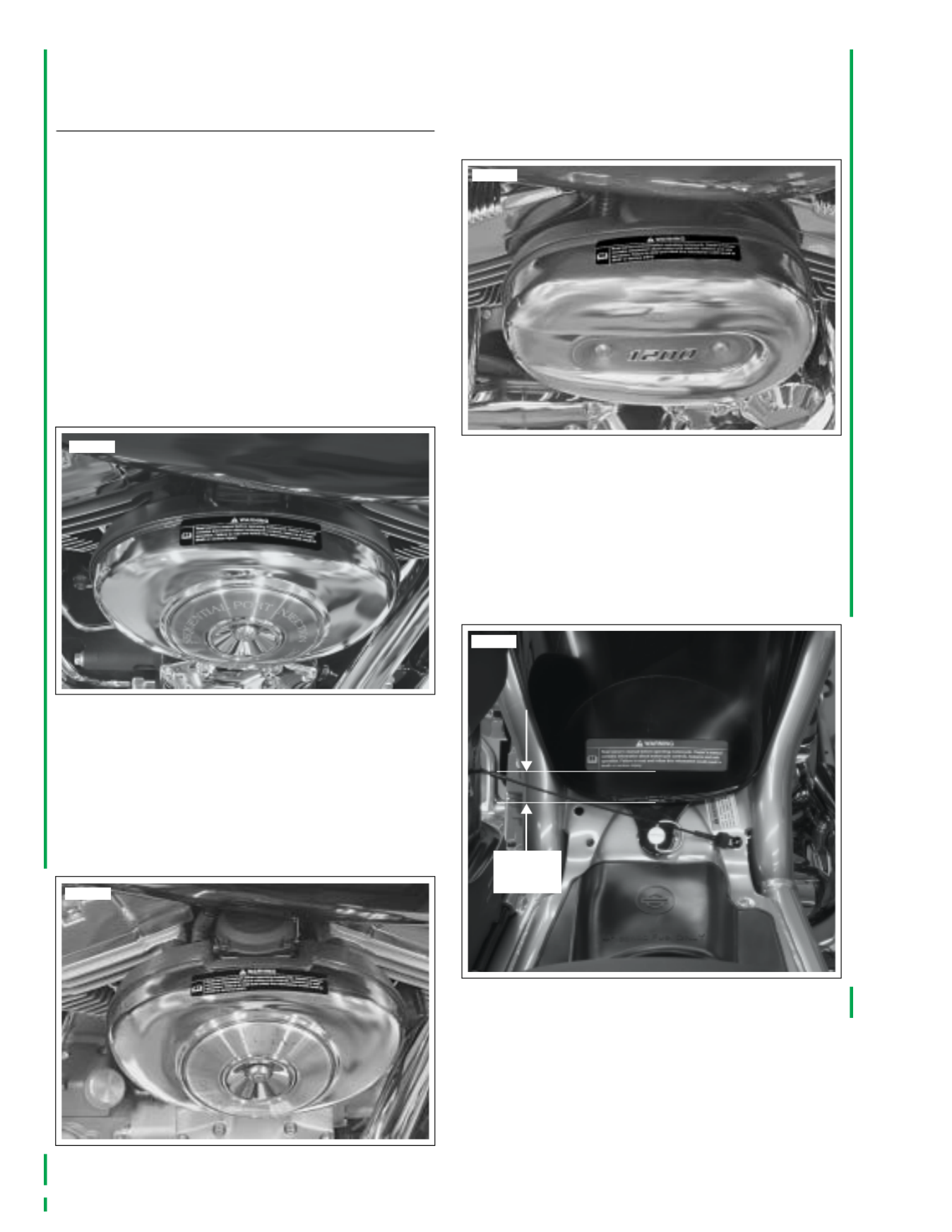
All EFI Big Twin Models
See Figure 1-30. Peel appropriate label from sheet. Apply
label on top of air cleaner cover, centered on cover and lined
up with edge of air cleaner back plate.
All Carbureted Big Twin Models
See Figure 1-31. Peel appropriate label from sheet. Apply
label on top of air cleaner cover, centered on cover and lined
up with edge of carburetor cutout in air cleaner back plate.
All Sportster Models
See Figure 1-32. Peel appropriate label from sheet. Apply
label on top of air cleaner cover, centered on cover and lined
up with edge of air cleaner back plate.
All VRSC Models
See Figure 1-33. Open seat. Peel appropriate label from
sheet. Apply label centered on rear end of air cleaner cover
with bottom edge of label 1.0 in. (25.4 mm) from rear edge of
air cleaner cover.
Figure 1-30. Warning Label Placement–
All Big Twin EFI (Typical)
Figure 1-31. Warning Label Placement–
All Big Twin Carbureted (Typical)
10683
10684
Figure 1-32. Warning Label Placement–
All Sportster Models (Typical)
Figure 1-33. Warning Label Placement–
All VRSC Models (Typical)
10685
10686
1.0 in
(25.4 mm)

2005 PDI: All Models 1-19
SYSTEM PROBLEMS 1.2
GENERAL
All system problems fall into at least one of three general cat-
egories.
No Start
The engine cranks over freely, but will not start. This does not
include situations where the engine will not crank, such as a
security disabled starter, dead battery, etc. This condition
assumes that all obvious checks (fuel in tank, etc.) have been
made.
Poor Performance
The engine starts but there are performance problems. These
problems may include poor fuel economy, rough idle, engine
misfire, engine hesitation, severe spark knock, etc.
Check Engine Lamp
The Check Engine lamp indicates the ECM has determined a
fault condition exists. There may also be starting or perfor-
mance problems.
In the event that you encounter any system problems during
set-up, see the appropriate Service Manual or Electrical
Diagnostic Manual for your model.

1-20 2005 PDI: All Models
NOTES

SUBJECT PAGE NO.
2.1 Specifications . . . . . . . . . . . . . . . . . . . . . . . . . . . . . . . . . . . . . . . . . . . . . . . . . 2-1
Torque Values . . . . . . . . . . . . . . . . . . . . . . . . . . . . . . . . . . . . . . . . . . . . . . . . 2-1
2005 Touring Models Specifications . . . . . . . . . . . . . . . . . . . . . . . . . . . . . . . 2-1
2.2 Initial Assembly . . . . . . . . . . . . . . . . . . . . . . . . . . . . . . . . . . . . . . . . . . . . . . . . 2-2
Battery Testing And Charging . . . . . . . . . . . . . . . . . . . . . . . . . . . . . . . . . . . . 2-2
Installing Maxi-Fuse . . . . . . . . . . . . . . . . . . . . . . . . . . . . . . . . . . . . . . . . . . . . 2-2
Installing Fuel Pump Fuse . . . . . . . . . . . . . . . . . . . . . . . . . . . . . . . . . . . . . . . 2-2
Installing Data Link Connector . . . . . . . . . . . . . . . . . . . . . . . . . . . . . . . . . . . . 2-3
Installing Tour-Pak . . . . . . . . . . . . . . . . . . . . . . . . . . . . . . . . . . . . . . . . . . . . . 2-3
Seats And Passenger Strap . . . . . . . . . . . . . . . . . . . . . . . . . . . . . . . . . . . . . . 2-4
Installing Sidecovers and Saddlebags . . . . . . . . . . . . . . . . . . . . . . . . . . . . . . 2-4
Radio Antenna Mast Installation . . . . . . . . . . . . . . . . . . . . . . . . . . . . . . . . . . 2-6
Rear Speaker Harnesses . . . . . . . . . . . . . . . . . . . . . . . . . . . . . . . . . . . . . . . . 2-6
Installing Windshield . . . . . . . . . . . . . . . . . . . . . . . . . . . . . . . . . . . . . . . . . . . . 2-7
Mirrors . . . . . . . . . . . . . . . . . . . . . . . . . . . . . . . . . . . . . . . . . . . . . . . . . . . . . . 2-10
Throttle Control Cables . . . . . . . . . . . . . . . . . . . . . . . . . . . . . . . . . . . . . . . . . 2-10
Rear Suspension Air Pressure . . . . . . . . . . . . . . . . . . . . . . . . . . . . . . . . . . . . 2-11
2.3 Lubrication System . . . . . . . . . . . . . . . . . . . . . . . . . . . . . . . . . . . . . . . . . . . . . 2-12
Engine Oil Level . . . . . . . . . . . . . . . . . . . . . . . . . . . . . . . . . . . . . . . . . . . . . . . 2-12
Engine Oil Level (Side Car Equipped Vehicles) . . . . . . . . . . . . . . . . . . . . . . . 2-12
Transmission Lubricant . . . . . . . . . . . . . . . . . . . . . . . . . . . . . . . . . . . . . . . . . 2-13
Chaincase Lubricant Level and Clutch Operation . . . . . . . . . . . . . . . . . . . . . 2-13
2.4 Fuel System . . . . . . . . . . . . . . . . . . . . . . . . . . . . . . . . . . . . . . . . . . . . . . . . . . . 2-14
General . . . . . . . . . . . . . . . . . . . . . . . . . . . . . . . . . . . . . . . . . . . . . . . . . . . . . . 2-14
Checking Quick Connect Fuel Line Fitting–Fuel Injected Models . . . . . . . . . 2-14
Fuel Tank . . . . . . . . . . . . . . . . . . . . . . . . . . . . . . . . . . . . . . . . . . . . . . . . . . . . 2-14
Evaporative Emissions Control System–California Models Only . . . . . . . . . . 2-15
2.5 Electrical System . . . . . . . . . . . . . . . . . . . . . . . . . . . . . . . . . . . . . . . . . . . . . . . 2-16
Headlamp . . . . . . . . . . . . . . . . . . . . . . . . . . . . . . . . . . . . . . . . . . . . . . . . . . . . 2-16
Auxiliary Lamps . . . . . . . . . . . . . . . . . . . . . . . . . . . . . . . . . . . . . . . . . . . . . . . 2-16
Directional Lamps . . . . . . . . . . . . . . . . . . . . . . . . . . . . . . . . . . . . . . . . . . . . . . 2-16
Front Turn Signals (FLHRS Only) . . . . . . . . . . . . . . . . . . . . . . . . . . . . . . . . . 2-16
Instrument Panel . . . . . . . . . . . . . . . . . . . . . . . . . . . . . . . . . . . . . . . . . . . . . . 2-16
Indicator Lamps/Controls . . . . . . . . . . . . . . . . . . . . . . . . . . . . . . . . . . . . . . . . 2-17
2.6 Tires . . . . . . . . . . . . . . . . . . . . . . . . . . . . . . . . . . . . . . . . . . . . . . . . . . . . . . . . . 2-18
Front and Rear Tires . . . . . . . . . . . . . . . . . . . . . . . . . . . . . . . . . . . . . . . . . . . 2-18
2.7 Brake System . . . . . . . . . . . . . . . . . . . . . . . . . . . . . . . . . . . . . . . . . . . . . . . . . 2-19
Brakes . . . . . . . . . . . . . . . . . . . . . . . . . . . . . . . . . . . . . . . . . . . . . . . . . . . . . . 2-19
ABS System (Police Vehicles–Optional Equipment) . . . . . . . . . . . . . . . . . . . 2-19
2.8 Dealer Road Test . . . . . . . . . . . . . . . . . . . . . . . . . . . . . . . . . . . . . . . . . . . . . . 2-20
Road Test . . . . . . . . . . . . . . . . . . . . . . . . . . . . . . . . . . . . . . . . . . . . . . . . . . . . 2-20
Idle Speed: Carbureted Only . . . . . . . . . . . . . . . . . . . . . . . . . . . . . . . . . . . . . 2-20
2.9 Customer Delivery . . . . . . . . . . . . . . . . . . . . . . . . . . . . . . . . . . . . . . . . . . . . . . 2-21
Notice To Dealer . . . . . . . . . . . . . . . . . . . . . . . . . . . . . . . . . . . . . . . . . . . . . . 2-21
2.10 Vehicle PDI Checklist . . . . . . . . . . . . . . . . . . . . . . . . . . . . . . . . . . . . . . . . . . 2-22
Prior to Customer Delivery . . . . . . . . . . . . . . . . . . . . . . . . . . . . . . . . . . . . . . . 2-22
At Point of Customer Delivery . . . . . . . . . . . . . . . . . . . . . . . . . . . . . . . . . . . . 2-22
II
PREDELIVERY: TOURING MODELS


2005 PDI: Touring Models 2-1
SPECIFICATIONS 2.1
TORQUE VALUES
The following torque values are included for fasteners that
may be loosened and tightened during Predelivery and
Setup. Any fasteners that are not loosened/removed do not
need to be checked during predelivery and setup.
2005 TOURING MODELS
SPECIFICATIONS
Idle Speed: 950 RPM at
Operating Temperature
Use 950 RPM during Predelivery and Setup adjustments.
Engine idle speed may increase during engine break-in. Use
idle speed listed in the Touring Models Service Manual at Ini-
tial Maintenance check.
NOTE
The idle speed on electronic fuel injected models can only be
set using a diagnostic tool such as DIGITAL TECHNICIAN
(Part No. HD-44750).
Table 2-1. Torque Values
ITEM TORQUE NOTES
Handlebar clamp screws (front and rear) 12-16 ft-lbs 16.3-21.7 Nm Must be checked at set-up.
Clutch inspection cover screws 84-108 in-lbs 9.5-12.2 Nm
FLHT windshield screws 25-30 in-lbs 2.8-3.4 Nm
FLTR windshield screws 6-13 in-lbs 0.7-1.5 Nm
Saddlebag mounting bracket bolts 60-96 in-lbs 6.8-10.8 Nm
Tour-Pak ® mounting bolts 96-120 10.8-13.5 Nmin-lbs
FLHR/
FLHP
Nacelle acorn nuts 72-108 in-lbs 8.1-12.2 Nm
Handlebar clamp shroud screws 10-20 in-lbs 1.1-2.3 Nm
Handlebar clamp shroud nut 10-20 in-lbs 1.1-2.3 Nm
Nacelle trim nut 15-20 in-lbs 1.7-2.3 Nm
Table 2-2. Capacities
Component ENGLISH METRIC
Oil tank w/lter (Dry) 4 qt. 3.79 liter
Transmission (Wet) 20-24 oz 591-710 ml
Primary Chaincase 32 oz 946 ml
All touring models except FLHTCSE 2 are shipped with
20W50 Harley-Davidson 360 Motor oil. The FLHTCSE 2
model ships with Syn-3 ® lubricant in the engine, primary
and transmission.
1

2-2 2005 PDI: Touring Models
INITIAL ASSEMBLY 2.2
BATTERY TESTING AND CHARGING
1WARNING1WARNING
Batteries contain sulfuric acid, which could cause severe
burns to eyes and skin. Wear a protective face shield,
rubberized gloves and protective clothing when working
with batteries. KEEP BATTERIES AWAY FROM CHIL-
DREN. (00063a)
1WARNING1WARNING
Never remove warning label attached to top of battery.
Failure to read and understand all precautions in warning
could result in death or serious injury. (00064a)
1WARNING1WARNING
Battery posts, terminals and related accessories contain
lead and lead components, chemicals known in the State
of California to cause cancer and birth defects or other
reproductive harm. Wash hands after handling. (00019a)
NOTE
It will be necessary to remove the left saddlebag and left side-
cover to gain access to the Maxi-Fuse connector.
1. Check battery voltage at Maxi-Fuse plug. With fuse
removed, place red voltmeter probe on battery side (ter-
minal A) of Maxi-Fuse plug, and black voltmeter probe on
a suitable ground.
2. If the open circuit (disconnected) voltage reading is 12.6
VDC or greater the battery is ready for use.
3. See Section 1. Mark the date on the battery warranty tag
by removing the applicable month and year. Month and
year punches may be removed with the point of a screw-
driver without removing battery.
4. If the open circuit (disconnected) voltage reading is
below 12.6 VDC, refer to Table 1-2, 28 amp-hour battery,
in Section 1 and charge battery at rate and time speci-
ed.
5. Recheck battery voltage by repeating step 1 above. If
voltage now is 12.6 VDC or greater, perform steps 2 and
3 above.
6. If the open circuit (disconnected) voltage reading is still
below 12.6 VDC, the battery must be replaced.
INSTALLING MAXI-FUSE
The 40 amp Maxi-Fuse provides battery power to the ignition
switch and ECM. The 40 amp Maxi-Fuse is not installed at
the factory. It is shipped in the saddlebag of the motorcycle.
and is to be installed under the left sidecover. Cut the cable
tie securing the Maxi-Fuse wire to the frame. See Service
Manual for Maxi-Fuse installation procedure.
INSTALLING FUEL PUMP FUSE
NOTE
It will be necessary to remove the right saddlebag and right
sidecover to gain access to the fuel pump fuse.
For fuel-injected vehicles, it will be necessary to install the 15-
amp fuel pump fuse that is located in the spare fuse slot of
the fuse-block located under the right sidecover. See Service
Manual.
2005 PDI: Touring Models 2-3
INSTALLING DATA LINK
CONNECTOR
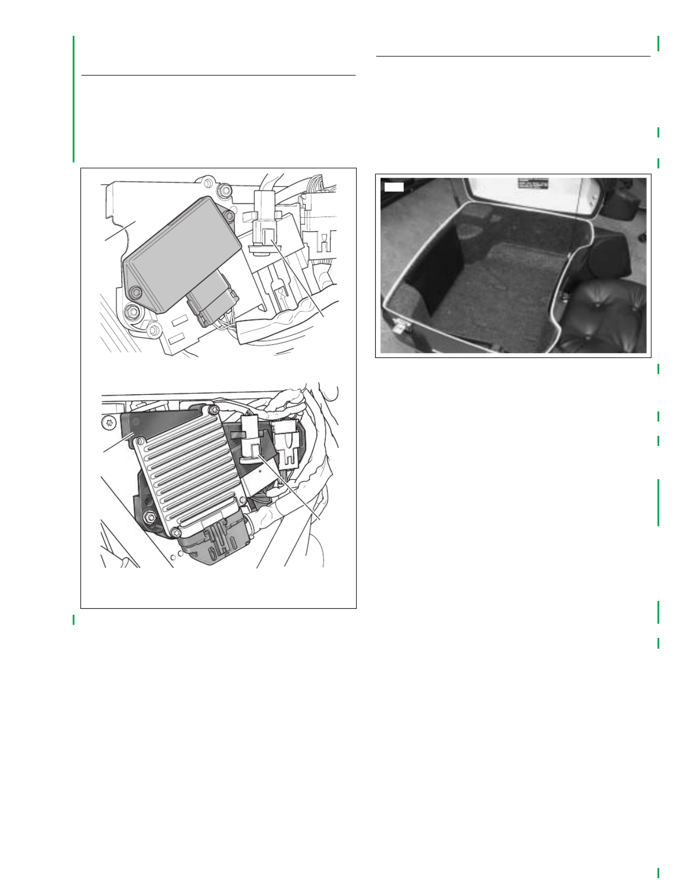
See Figure 2-1. The data link connector [91] (2) mounts in a
clip on the electrical bracket (1) under the right side cover.
Cut the cable tie securing the data link connector harness to
the frame and snap the connector into its clip on the electrical
bracket.
INSTALLING TOUR-PAK ®
NOTE
The seat screw is not factory installed on models with Tour-
Paks. The seat screw is in the Parts Kit, Part No. 53318-99.
On Ultra models, see Figure 2-2. Remove map pouch and
molded Tour-Pak liner from Tour-Pak prior to performing the
following procedures. Install both after work is completed.
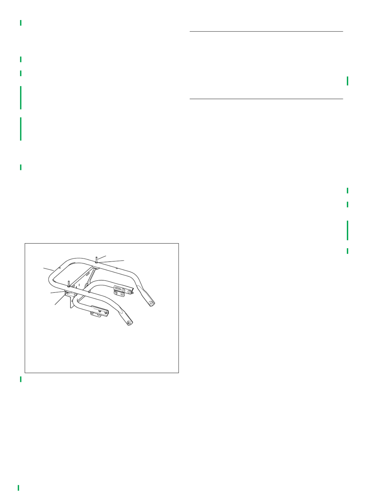
Five Bolt Mounting
Note that Tour-Pak has seven mounting holes which allow it
to be positioned forward on luggage rack for shipping
only. Mount Tour-Pak in the rearward position (front four
holes and rear center hole) so seat access screw can be
reached.
1. To avoid dropping or scratching the Tour-Pak, disconnect
the radio antenna cable and Tour-Pak lights connectors
and feed wiring out through hole at front of Tour-Pak
(after removing grommet). On Ultra models, repeat the
procedure to release the CB antenna cable and connec-
tor.
2. If not already removed, remove seat.
3. Place a protective blanket across the frame tubes in the
seat area.
4. From inside Tour-Pak, remove the nuts and oversized
shipping washers and then lift the Tour-Pak off the
mounting bolts setting it on the blanket. Retain nuts for
use later, discard large shipping washers.
Figure 2-1. Data Link Connector
1. Electrical bracket
2. Data link connector [91]
pd0215
Carbureted
Fuel injected
1
1
2
2
pd0216
Figure 2-2. Tour-Pak Liner and Map Pouch
5029
2-4 2005 PDI: Touring Models
5. See Figure 2-3. Remove and discard the pushnuts (5)
from the mounting bolts (1), and pull the bolts (1) and
washers (2) from the luggage rack (although the spacers
(4) may be left in place between the top support tube (3)
and the license plate bracket).
6. Locate Parts kit, Part no. 53318-99 in Tour-Pak or sad-
dlebag. The plastic bag contains three spacers, bolts,
nuts and ve washers used to mount Tour-Pak. Also in
parts kit is the seat retaining screw.
7. See Figure 2-4. Move Tour-Pak to rear so ve mounting
holes align with ve holes in top support tube.
NOTE
Make certain bolts are installed with threaded end down. Bolt
head and washer must be inside Tour-Pak.
8. From inside Tour-Pak, install right rear bolt (1) and
washer (2) through bottom of Tour-Pak, hole in top sup-
port tube (3), luggage rack spacer (4), and hole in
license plate bracket (5).
9. Install washer (2) and locknut (6) on right rear bolt and
tighten “nger-tight”. (This fastener will keep Tour-Pak in
position while remaining four bolts are installed.)
10. Install antenna ground lead ring terminal under washer
of rear mounting bolt and install rear bolt as shown in
Figure 2-4.
11. Install remaining bolts, washers, spacers and nuts as
shown in Figure 2-4.
12. Tighten ve nuts and bolts to 96-120 in-lbs (10.8-13.5
Nm).
SEATS AND PASSENGER STRAP
Refer to Touring Models Owner’s Manual for seat and pas-
senger strap removal and installation instructions. Road Glide
models must have the seat strap installed per the appropriate
Service Manual.
INSTALLING SIDECOVERS AND
SADDLEBAGS
Check that each saddlebag is rmly seated on its saddlebag
bottom support rail. Check that adequate clearance exists
between saddlebags and sidecovers. The front and rear
mounting brackets of each saddlebag have slotted mounting
holes (on the bracket ends which attach to the motorcycle) to
allow for vertical adjustment of the saddlebag. If adjustment is
necessary, loosen the bolts which secure the saddlebag
mounting brackets to the motorcycle. Press down and to the
rear rmly on closed saddlebag, and then tighten the bolts to
60-96 (6.8-10.8 Nm) torque.in-lbs
NOTE
It is essential that the Tour-Pak be installed in the rearward
position or seat removal/installation will not be possible due to
interference with the forward-mounted Tour-Pak.
On Ultra models, see Figure 2-5. Check that AM/FM/WB
antenna (left side) cable is in its two clips on left side of Tour-
Pak floor. Also check that CB antenna (right side) cable is in
two clips on right side of Tour-Pak floor. Verify that ground
strap of AM/FM/WB antenna is securely fastened to base
plate in Tour-Pak with rear mounting screw.
Figure 2-3. Tour-Pak Shipping Fasteners
1. Bolt, 1/4-20 x 2-1/4 in. (2)
2. Washer 1/4 in. inside dia. (2) (under bolt head)
3. Top support tube
4. Luggage rack spacer (2)
5. Pushnuts (2)
1
2
3
4
5
pd0188
2005 PDI: Touring Models 2-5
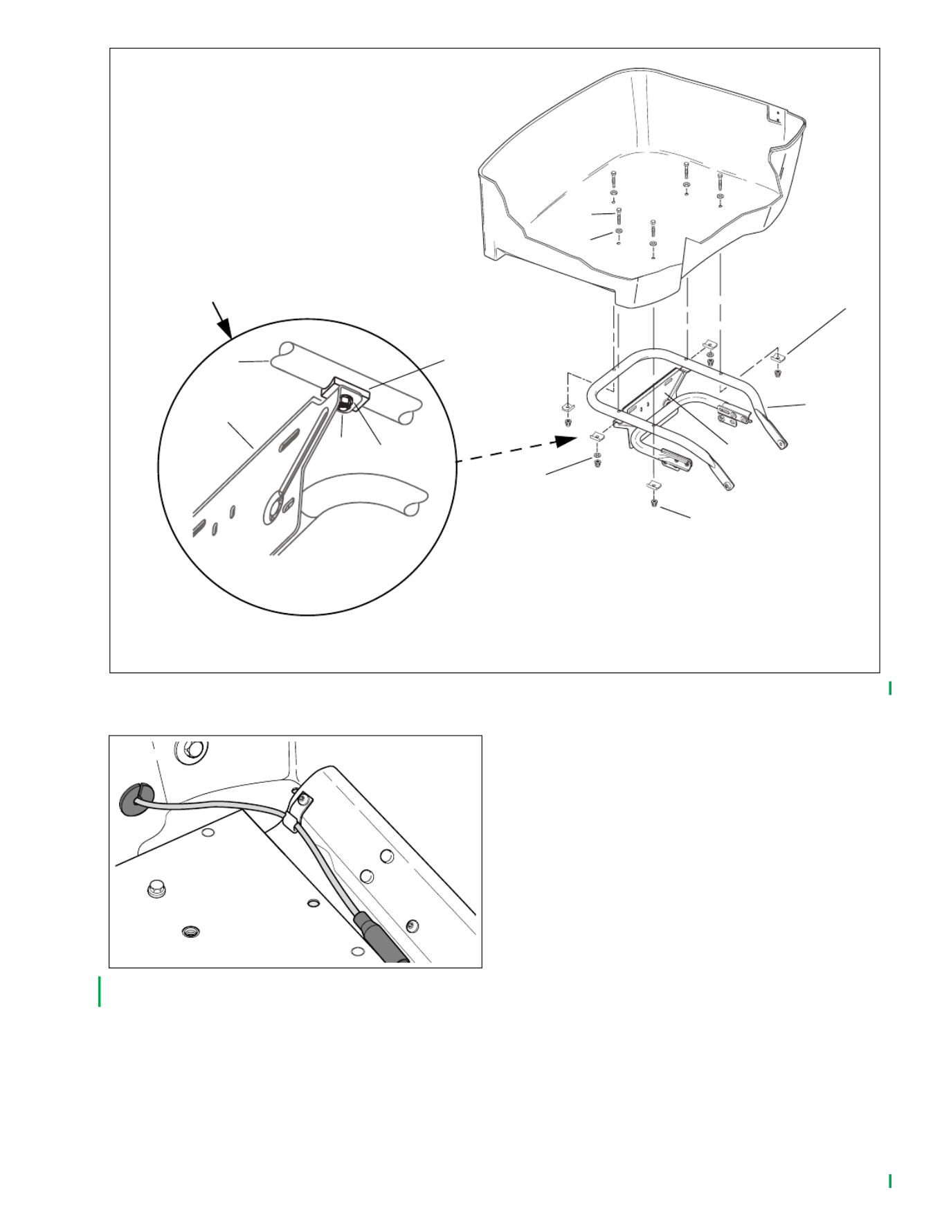
Figure 2-4. Tour-Pak Mounting
Bottom view showing
spacer (4) between license
plate bracket (5) and top
support tube (3).
1. Bolt, 1/4-20 x 2-1/4 in. (5)
2. Washer 1/4 in. inside dia. (7)
3. Top support tube
4. Luggage rack spacer (5)
5. License plate bracket
6. Locknut, Nylon cap, 1/4-20 (5)
pd0187e
5
3
4
2
1
6
4
2
6
3
5
2
Figure 2-5. Antenna Cable Clip
(CB Antenna Cable Shown)
f1467b2x
2-6 2005 PDI: Touring Models
RADIO ANTENNA MAST
INSTALLATION
Open the Tour-Pak lid.
FLHTC models are equipped with one antenna mast. Thread
the mast securely over the antenna mounting stud and
tighten the set screw.
FLHTCU models are equipped with two antenna masts —
one with loading coil for CB radio for right side mounting, the
other for AM/FM radio for left side.
On Ultra models only, use soapy water as a lubricant to install
a protective rubber boot (provided with vehicle) over tip of
AM/FM antenna mast; slide boot down mast and over spring-
loaded base. Repeat for CB antenna, but, loosen upper set-
screw in base, slide mast from base and slide boot onto mast
below loading coil. Reassemble mast to base and adjust dis-
tance between bottom of loading coil to top of base to 1 in.
Thread each mast securely over its antenna mounting stud.
Tighten the two (3 on CB) set screws (one for antenna mast,
the other for antenna mounting stud) located in the spring-
loaded base of each antenna and one at top of loading coil.
NOTE
Standing Wave Ratio (SWR) will be checked later in these
procedures.
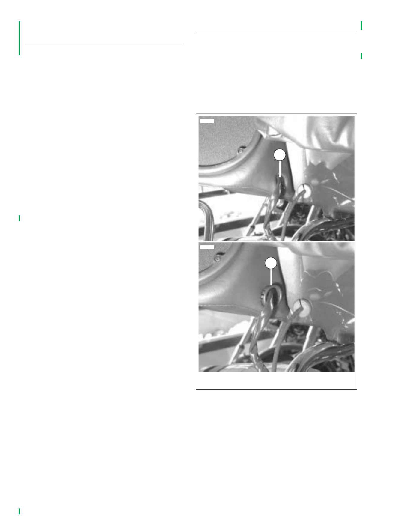
REAR SPEAKER HARNESSES
1. See Figure 2-6. Cut cable straps securing rear speaker
harnesses to passenger handrail (both right and left
sides). Locate plastic grommets packed in Tour-Pak.
2. Press down on seat cushion, slide harness and connec-
tor into speaker box.
3. Install split plastic grommet on harness and push grom-
met into hole in speaker box.
4. Repeat steps 2 and 3 for left side.
Figure 2-6. Rear Speaker Harness Grommets
(Seat removed for clarity)
1
2
1. Right speaker harness
2. Plastic grommet (shown partially installed)
6712
6711
2005 PDI: Touring Models 2-7
INSTALLING WINDSHIELD
FLHTC, FLHTCU, FLHTCSE 2 (Wind Deec-
tor) and FLHTP (Fairing)
1. See Figure 2-7. Loosen the three fasteners along the top
of the outer fairing. It is not necessary to remove the fas-
teners.
2. Slide windshield down between the inner and outer fair-
ing over the fasteners. Position on the raised boss on the
inner fairing.
CAUTION
Overtightening windshield fasteners may crack wind-
shield and/or fairing.
3. Tighten fasteners to 25-30 in-lbs (2.8-3.4 Nm).
Windshield Installation: FLTR
1. See Figure 2-8. Place black plastic washers (4) on the
ve mounting screws (3). Position rubber trim along bot-
tom of windshield. Insert screws through windshield
holes and thread loosely into ve Wellnuts (5) with rubber
washers (6).
2. Push Wellnuts with rubber washers into holes in fairing.
3. Beginning with the center screw and working outward
toward the rear edges of windshield, tighten all screws to
6-13 in-lbs (0.7-1.5 Nm). Make certain that the four outer
screws are located at the upper end of the slots in the
windshield.
Figure 2-7. Windshield Installation–FLHT Models
pd0173x
Figure 2-8. Windshield Installation–FLTR Models
f2280x2x
1. Windshield
2. Outer fairing
3. Screw (5)
4. Flat washer (plastic) (5)
5. Wellnut (5)
6. Flat washer (rubber) (5)
1
2
3
4
5
6
2-8 2005 PDI: Touring Models
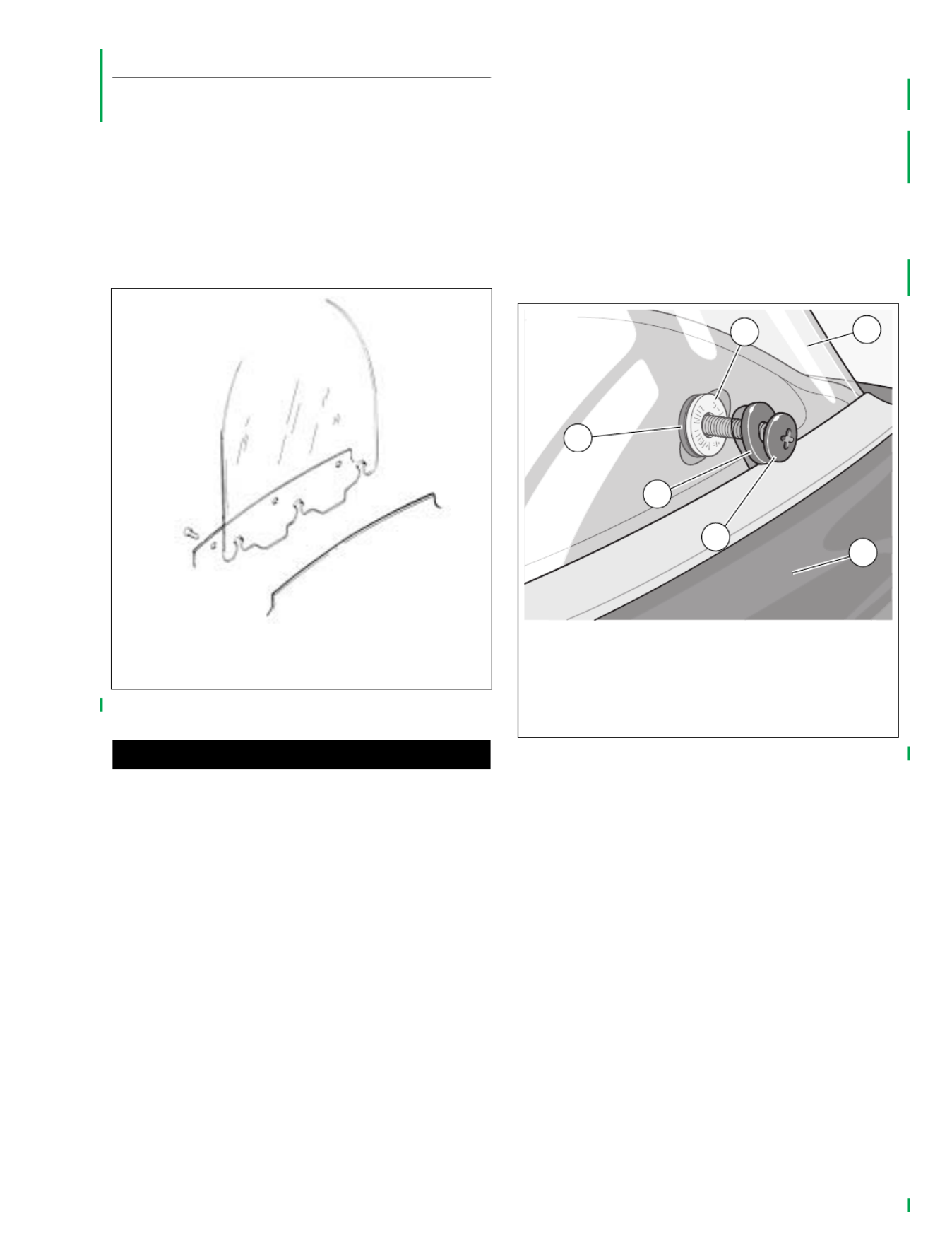
Windshield Installation: FLHR/C and
FLHP (Windshield)
CAUTION
Be sure you position the windshield bracket between the
rubber grommets. Incorrect mounting could result in
damage to the windshield.
See Figure 2-9. Insert your ngers into the wireform latch
springs at either side of the windshield and slide the BOT-
TOM windshield bracket notches onto the bottom grommets.
Slide the TOP bracket notches onto the top grommets.
NOTE
If windshield contacts clutch cable, reposition handlebars.
Seat Adjustment: FLHTP
Before applying load to the seat, refer to the Police Models
Owner’s Manual for adjustment procedures of the FLHTP air-
suspension seat. Conrm that air bladder is inated to 10-psi
(69 kPa) minimum.
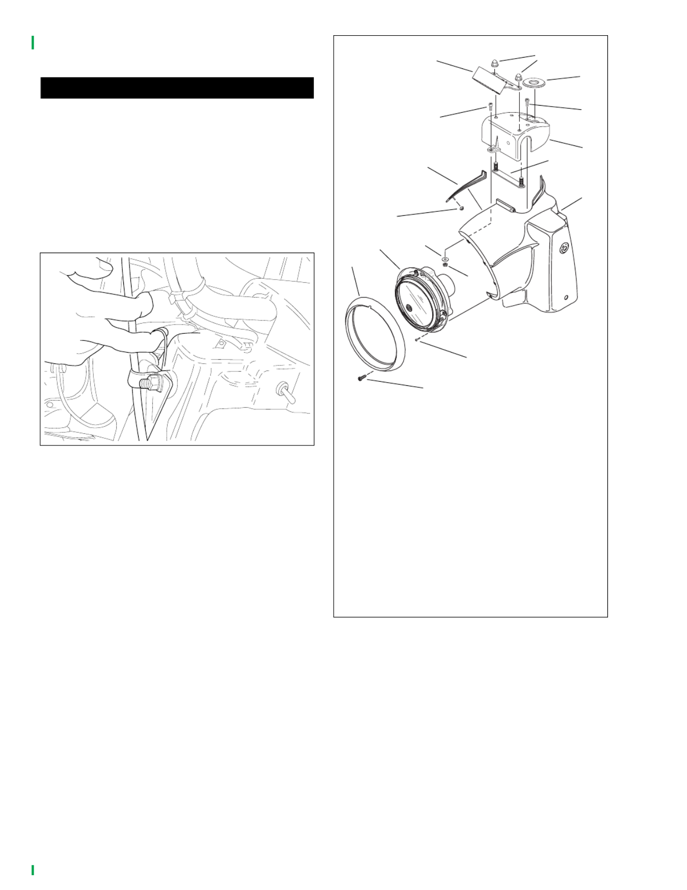
Instrument Mounting Bracket
Installation: FLHP
The FLHP is provided with an instrument mounting bracket.
The bracket relocates the tachometer to allow the addition of
a radio speaker, and control panel.
1. See Figure 2-10. Remove screw (13) securing chrome
ring (12) to headlamp nacelle (8). Remove chrome ring.
2. Remove eight fasteners (11) securing headlamp assem-
bly (10). Squeeze two external tabs (if present) to
remove wire connector at back of headlamp bulb.
Remove headlamp assembly from vehicle.
Figure 2-9. FLHR/C and FLHP Windshield Installation
OMF53
Figure 2-10. FLHP Headlamp Nacelle
pd0227
3
2
1
4
8
1. Nut
2. Nacelle trim
3. Screw
4. Nut
5. Flat washer
6. Fork lock plate
7. Screw (2)
8. Nacelle
9. Handlebar clamp shroud
10. Headlamp assembly
11. Screw (8)
12. Chrome headlamp ring
13. Screw
14. Stud plate
15. Acorn nut (2)
16. Tachometer bracket
10
11
13
12
7
9
14
6
15
16
5
2005 PDI: Touring Models 2-9
3. Remove nut (1) (inside nacelle) securing nacelle trim (2).
4. Disconnect tachometer connector [108] inside headlamp
nacelle.
5. Remove nacelle trim. Loosen (but do not remove) front
handlebar clamp shroud screw (3), nut (4) and washer
(5).
6. Gently pry off fork lock plate (6) at rear of handlebar
clamp shroud. Remove two screws (7) beneath lock
plate.
7. Loosen four acorn nuts securing nacelle halves to fork
studs. Spread nacelle halves slightly and remove handle-
bar clamp shroud.
8. Remove two acorn nuts (15) and at washers securing
Tachometer and bracket (16) to handlebar clamp shroud.
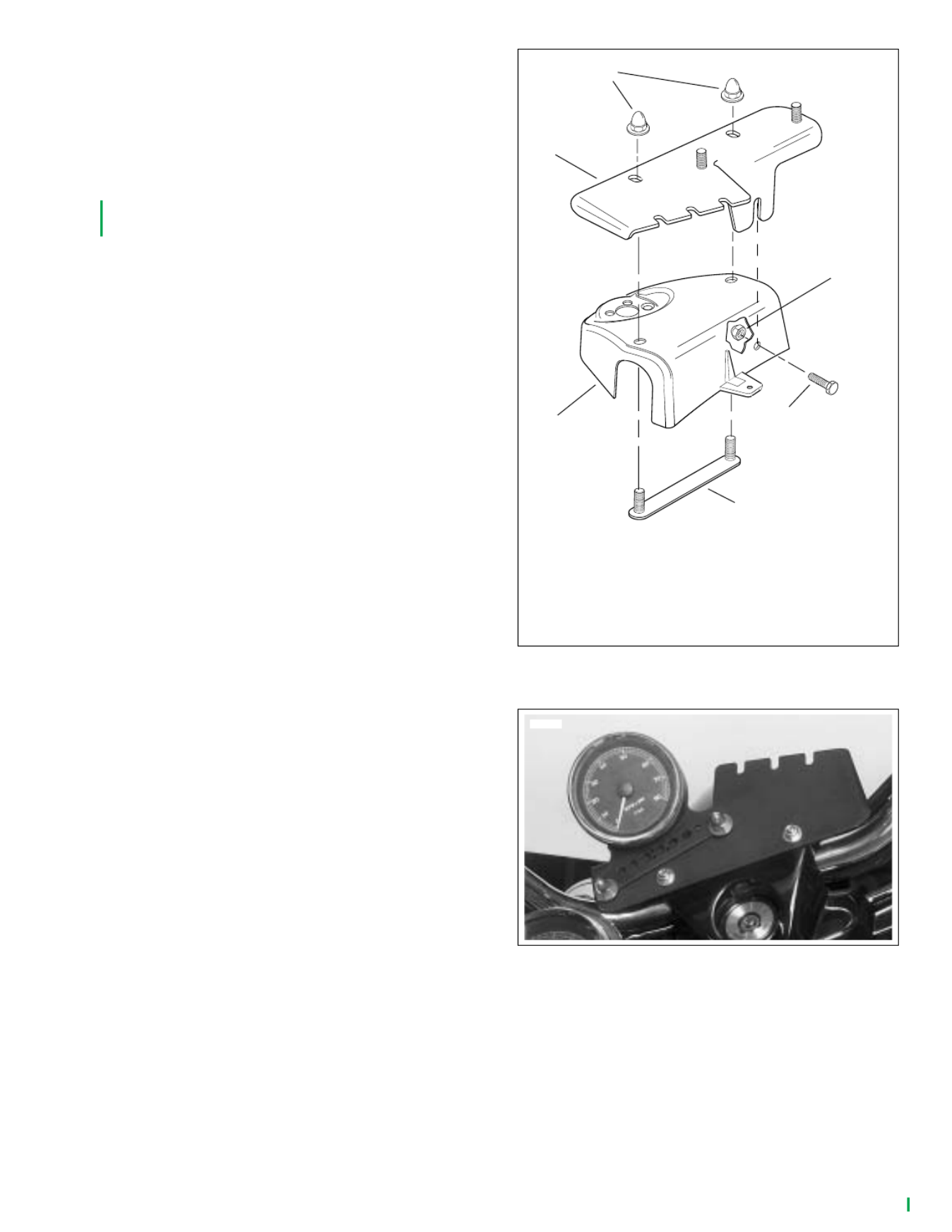
9. See Figure 2-11. A peel and stick foam tape holds the
stud plate (4) in place inside the handlebar clamp shroud
(3). Position instrument mounting bracket (2) on studs of
stud plate and secure in position using hardware pro-
vided by radio manufacturer (1).
10. Using screw (5) and nut (6) provided, secure front tab of
instrument mounting bracket on handlebar clamp
shroud.
11. Reinstall handlebar clamp shroud. Tighten acorn nuts
securing nacelle halves to fork studs to 72-108 in-lbs
(8.1-12.2 Nm).
12. See Figure 2-12. Mount tachometer on bracket with
acorn nuts and at washers as shown.
13. See Figure 2-10. Install two screws (7) to handlebar
clamp shroud and tighten to 10-20 in-lbs (1.1-2.3 Nm).
Gently press fork lock plate (6) into place on handlebar
clamp shroud.
14. Tighten front handlebar clamp shroud nut (4) to 10-20 in-
lbs (1.1-2.3 Nm).
15. Connect tachometer lead [108].
16. Install nacelle trim (2). Install nut (1) (inside nacelle) secur-
ing nacelle trim. Tighten to 15-20 in-lbs (1.7-2.3 Nm).
17. Connect wire connector to socket on back of headlamp
bulb. Install and secure headlamp assembly to nacelle
with eight fasteners.
18. Secure chrome ring (12) to headlamp nacelle with screw
(13).
NOTE
Check for adequate clearance between windshield and clutch
cable and handlebar position prior to completing assembly of
vehicle.
Figure 2-11. FLHP Instrument Bracket
Figure 2-12. FLHP Tachometer Mount
p0044x5x
1. Nut (2)
2. Instrument mounting bracket
3. Handlebar clamp shroud
4. Stud plate
5. Screw
6. Nut
3
2
4
6
1
5
5530
2-10 2005 PDI: Touring Models
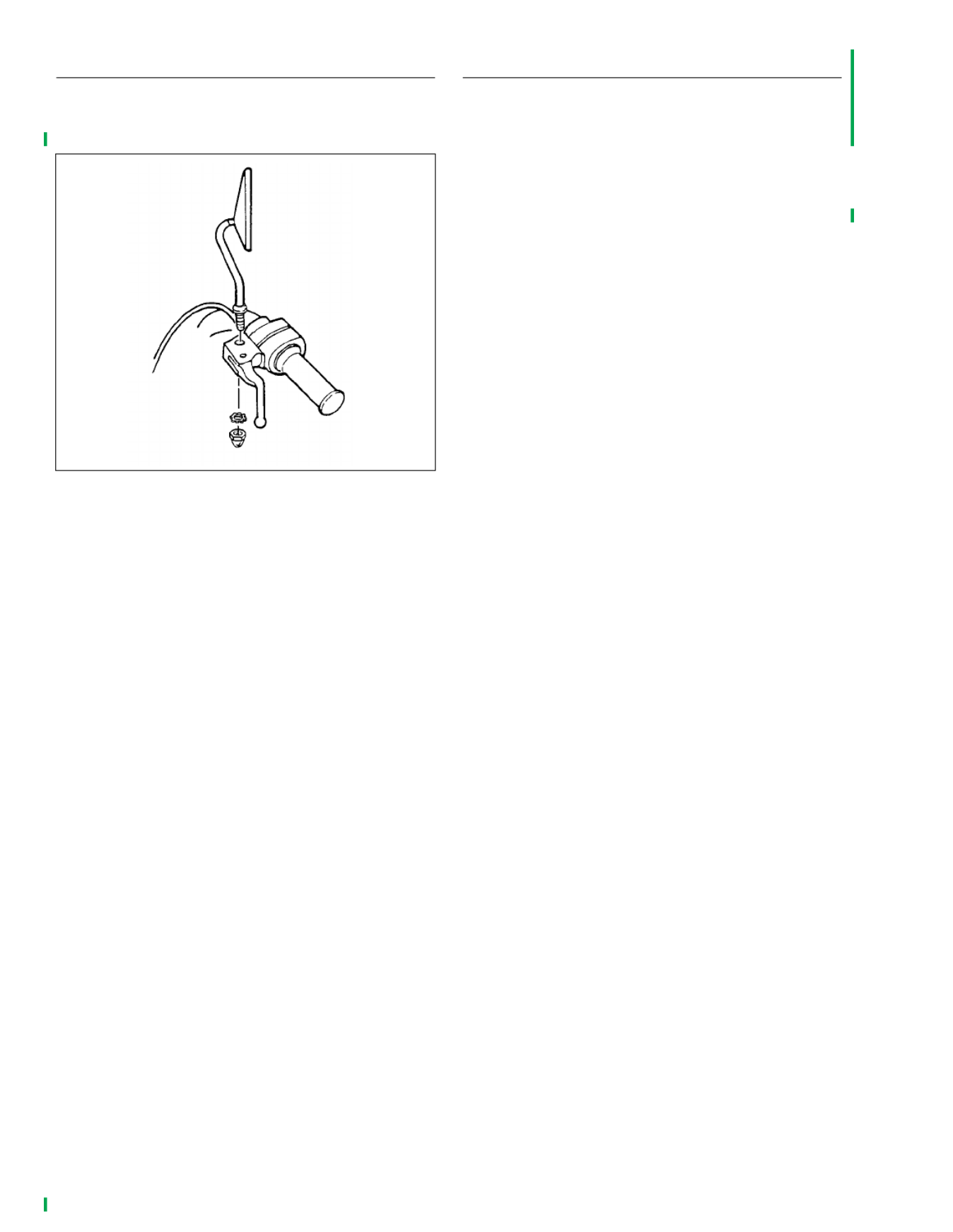
MIRRORS
See Figure 2-13. Adjust mirrors for proper rear view. Verify
that mirror fasteners are properly tightened.
THROTTLE CONTROL CABLES
All Non-Ultra Models
Check throttle cable adjustment in accordance with proce-
dure given in Section 1 of Touring Models Service Manual.
Ultra Models
Check throttle cable adjustment in accordance with proce-
dure given in Section 8 of Touring Models Service Manual.
Figure 2-13. Mirror Installation
pdoo72b
2005 PDI: Touring Models 2-11
REAR SUSPENSION
AIR PRESSURE
CAUTION
Do not exceed maximum air pressure for rear suspen-
sion. Air components ll rapidly. Therefore, use low air
line pressure. Failure to do so may result in possible
damage to components. (00165a)
IMPORTANT NOTE
Maximum air pressure of rear suspension system is 50
psi (345 kPa).
See Figure 2-14. Check rear suspension air pressure at air
valve located on the left side of the motorcycle below the
frame cover, above the left saddlebag. Refer to Table 2-3.
These are recommended starting points, adjust to suit load
conditions, riding style and comfort desired. Less initial pres-
sure does not necessarily result in a softer ride. Use a no-loss
gauge, add 3-5 psi (20.68-34.48 kPa) to clear line and adjust
for application.
Figure 2-14. Rear Suspension Air Pressure Valve
8472
Table 2-3. Rear Suspension Air Pressure (All Models Except FLHRS)
Loading
Pressure
psi kPa
Solo rider -150 lbs (68.0 kg) maximum 0 0
Solo rider 150-200 lbs (68.0-90.7 kg) 0-10 0-69
Solo rider 200-250 lbs (90.7-113.4 kg) 5-15 35-103
Rider and 150 lbs (68.0 kg) passenger 10-15 69-103
Rider and 200 lbs (90.7 kg) passenger 20-25 138-172
Gross vehicle weight rating (GVWR) 20-35 138-241
Table 2-4. Rear Suspension Air Pressure (FLHRS and FLHTCSE 2 Only)
Loading
Pressure
psi kPa
Solo rider -160 lbs (73.0 kg) maximum 0-5 0-35
Solo rider 160-200 lbs (73.0-90.7 kg) 0-10 0-69
Solo rider 200-250 lbs (90.7-113.4 kg) 5-10 35-69
Rider and 150 lbs (68.0 kg) passenger 20-30 138-207
Rider and Over 150 lbs (68 kg) passenger 25-35 172-241
Gross vehicle weight rating (GVWR) 40-50 276-345
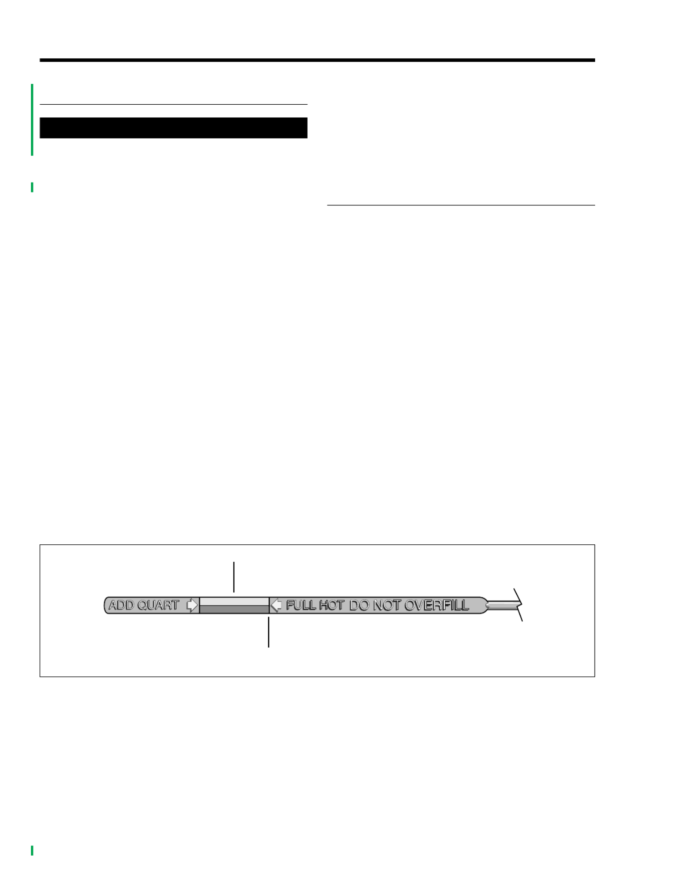
2-12 2005 PDI: Touring Models
LUBRICATION SYSTEM 2.3
ENGINE OIL LEVEL
CAUTION
The FLHTCSE 2 model is shipped from the factory with
SYN-3® lubricant exclusively in the engine, primary and
transmission. If there is a need to top off lubricants, DO
NOT use standard lubricants in the FLHTCSE 2 model and
do not mix lubricants as damage to the motorcycle can
result.
IMPORTANT NOTE
Oil level cannot be accurately measured on a cold
engine. For preride inspection with motorcycle leaning
on jiffy stand on level ground, oil should register on dip-
stick between arrows when engine is cold. Do NOT add
oil to bring the level to the FULL mark on a COLD engine.
Perform engine oil level COLD CHECK as follows:
1. With the vehicle resting on the jiffy stand on level ground,
remove the dipstick, wipe it off and insert it back into the
oil pan with the plug pushed completely into the ll spout.
2. Remove the dipstick and note the level of the oil. Oil level
should register on the dipstick. See Figure 2-15. If oil
level is at or below the lower arrow, add only enough oil
to bring the level to the add arrow on the dipstick.
NOTE
Once the predelivery inspection procedure is complete and
the vehicle has been road-tested, the engine oil level should
be checked again as described in the following procedure.
Perform engine oil level HOT CHECK as follows:
1. With the vehicle resting on the jiffy stand on level ground,
allow engine to idle for 1-2 minutes. Turn engine off.
2. Remove the dipstick, wipe it off and insert it back into the
oil pan with the plug pushed completely into the ll spout.
3. Remove the dipstick and note the level of the oil. Add
only enough oil to bring the level to the FULL mark on the
dipstick. See Do not overll.Figure 2-15.
4. Start engine and carefully check for oil leaks around
drain plug and oil lter.
ENGINE OIL LEVEL (SIDE CAR
EQUIPPED VEHICLES)
NOTE
Since a motorcycle equipped with a sidecar is xed in an
upright position, the engine oil level reading must be adjusted
in this case; the actual FULL engine oil level will be about 1/2
inch above the original FULL mark on the oil tank dipstick.
To insure the correct oil level with sidecar attached perform
the following:
1. Without sidecar attached, check engine oil level with
engine at normal operating temperature. See HOT
CHECK procedure above.
2. Verify oil level is at FULL mark on dipstick (add oil if
needed).
3. With sidecar attached, ride until engine is at normal
operating temperature.
4. On a level surface, note engine oil level on dipstick.
5. Scribe a line on dipstick at the oil level noted in step 4
above. The scribed line is the FULL mark for sidecar
operation.
Figure 2-15. Engine Oil Dipstick
f1254b3x
COLD CHECK
HOT CHECK
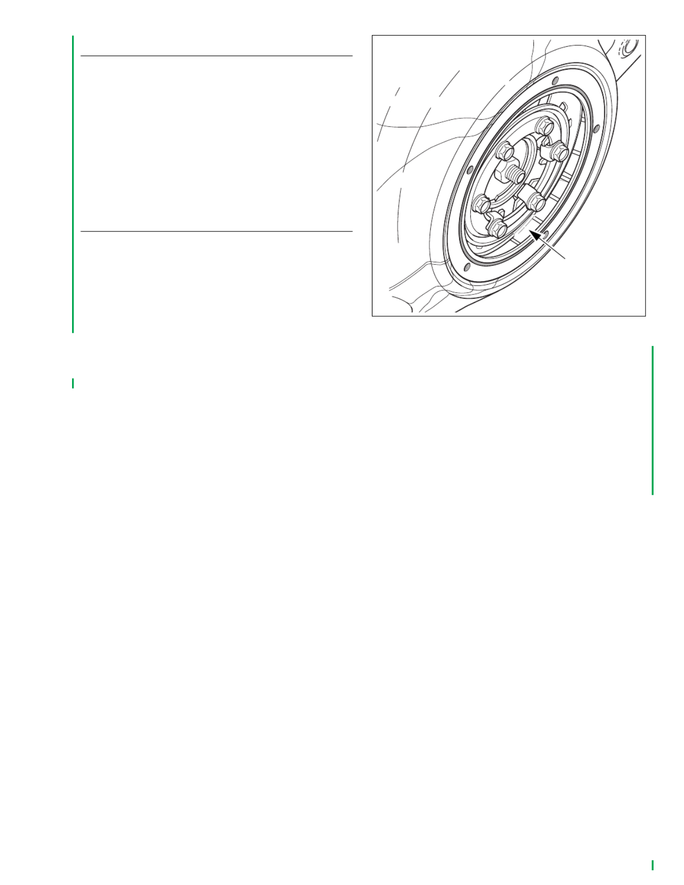
2005 PDI: Touring Models 2-13
TRANSMISSION LUBRICANT
NOTE
Allow vehicle to stand upright for a moment before checking
transmission lubricant level. This will allow lubricant level to
normalize.
Check the transmission lubricant level with the motorcycle
standing upright in accordance with the procedure given in
the Touring Models Service Manual.
CHAINCASE LUBRICANT LEVEL
AND CLUTCH OPERATION
NOTE
Do not remove the clutch cover on the FLHTCSE 2. It is not
necessary to check the primary chaincase lubricant level on
this vehicle. Also, the hydraulic clutch is not adjustable.
1. Remove ve screws, clutch inspection cover and cover
gasket.
2. See Figure 2-16. The primary chaincase lubricant level is
acceptable when lubricant is visible in bottom of chain-
case with motorcycle standing upright (not resting on jiffy
stand).
3. Check clutch action. Clutch lever should move freely and
smoothly through its entire range of travel.
4. Check clutch adjustment according to the procedures
given in the Touring Models Service Manual.
NOTE
The clutch inspection cover gasket may be reused ONLY
when checking chaincase lubricant level and reinstalling
clutch inspection cover at PDI.
5. Reinstall cover gasket and clutch inspection cover, and
secure with ve screws. Tighten to 84-108 in-lbs (9.5-
12.2 Nm).
Figure 2-16. Chaincase Lubricant Level
pd0206
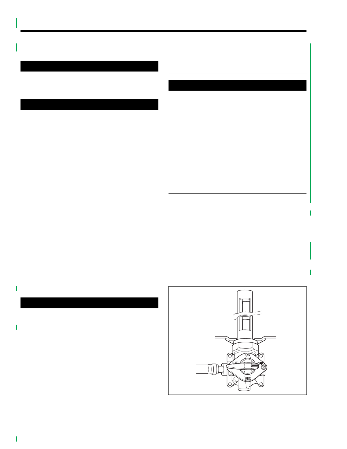
2-14 2005 PDI: Touring Models
FUEL SYSTEM 2.4
GENERAL
CAUTION
Some fuel suppliers sell gasoline which has been
blended with an alcohol or an ether. The type and amount
of alcohol or ether added to the fuel is important.
CAUTION
Do not use gasoline that contains methanol. Doing so
can result in fuel system component failure, engine dam-
age and/or equipment malfunction. (00148a)
●Gasolines containing ETHANOL (ethyl alcohol or grain
alcohol) can be used. Gasoline/ethanol blends are a mix-
ture of 10% ethanol and 90% unleaded gasoline. They
are identified as “gasohol,” “ethanol enhanced,” or “con-
tains ethanol.”
●Gasolines containing METHYL TERTIARY BUTYL
ETHER (MTBE) can also be used. Gasoline/MTBE
blends are a mixture of gasoline and as much as 15%
MTBE.
●REFORMULATED OR OXYGENATED GASOLINES
(RFG): “Reformulated gasoline” is a term used to
describe gasoline blends that are specifically designed to
burn cleaner than other types of gasoline, leaving fewer
“tailpipe” emissions. They are also formulated to evapo-
rate less when you are filling your tank. Reformulated
gasolines use additives to “oxygenate” the gas. Your
motorcycle will run normally using this type of gas and
Harley-Davidson recommends you use it when possible,
as an aid to cleaner air in our environment
Because of their different chemical properties (which affect
fuel volatility and ignition characteristics), these blends may
adversely affect the starting, drivability, and fuel efficiency of
the motorcycle. If you experience these problems, Harley-
Davidson recommends using straight, unleaded gasoline.
CAUTION
Use only unleaded fuel in California model catalytic con-
verter-equipped motorcycles. Using leaded fuel will dam-
age the emission control system. (00150a).
CHECKING QUICK CONNECT FUEL
LINE FITTING–FUEL INJECTED
MODELS
1WARNING1WARNING
To avoid an uncontrolled discharge or spray of gasoline,
always be sure the quick-connect tting (under left side
of fuel tank) is properly mated. A slight tug on the fuel
line will verify this condition. Gasoline is extremely am-
mable and highly explosive. Inadequate safety precau-
tions could result in death or serious injury.
1. Tug on fuel supply line (under left side of fuel tank) to be
sure quick connect fitting is properly mated.
2. If fuel line comes free, push up on sleeve of quick-con-
nect fitting and insert neck of fuel supply line fitting. While
pushing up on bottom of fuel supply line fitting, pull down
on sleeve until it “clicks” into the locked position.
FUEL TANK
Make sure engine stop switch on the handlebar is switched to
the OFF position. Turn the ignition/light switch to the IGNI-
TION position. Fuel injected models: verify that Low Fuel
lamp is lit. Partially fill fuel tank with gasoline. Follow FUEL
recommendations found in the Owner’s Manual. Use
unleaded gasoline, 91 octane or higher. Verify function of fuel
gauge as fuel tank is filling, then turn ignition/light switch OFF.
Inspect fuel lines for leaks.
Carbureted Models
See Figure 2-17. After adding gasoline, check for smooth
operation of the fuel valve. Inspect fuel valve for leaks.
Figure 2-17. Fuel Supply Valve
o0046box
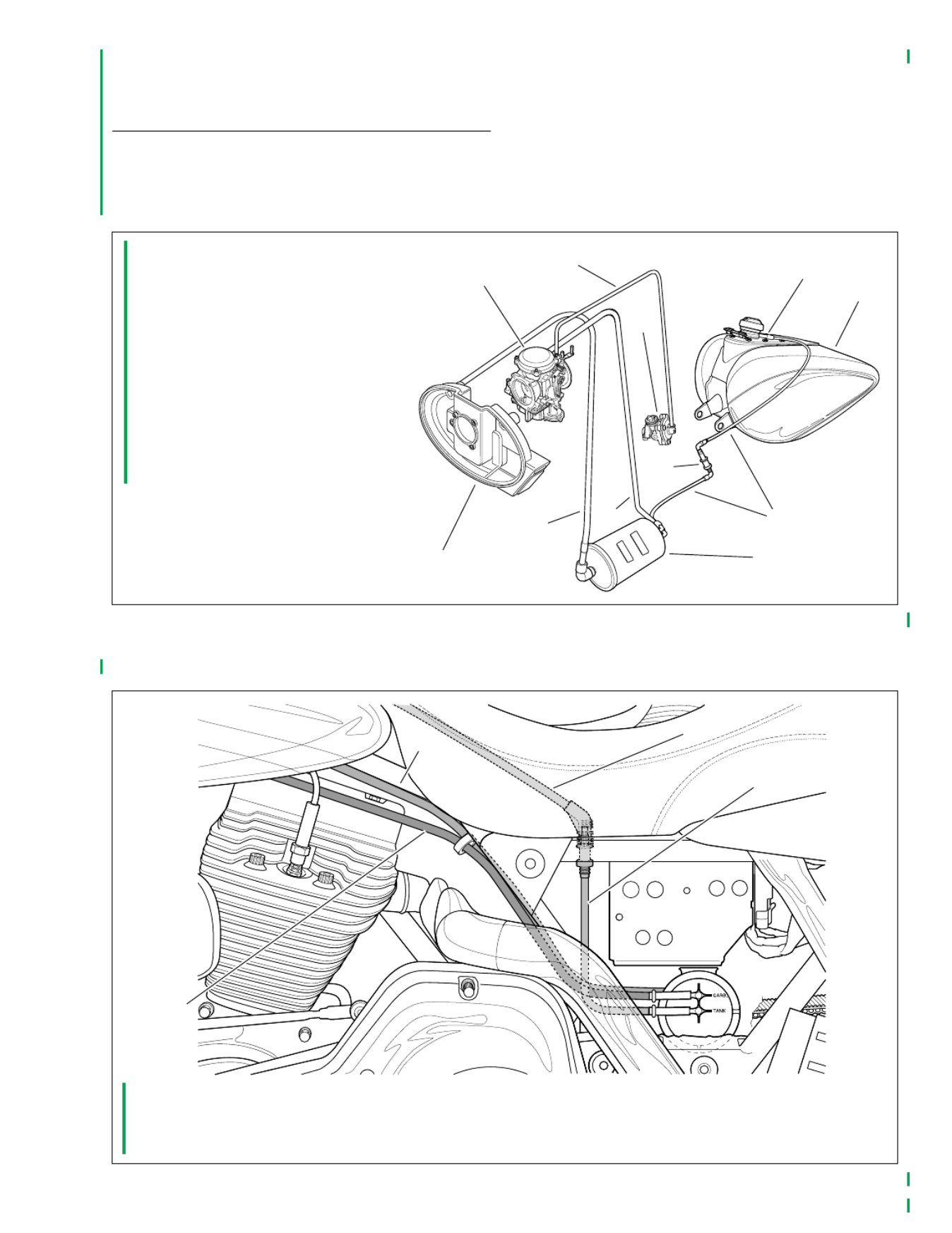
2005 PDI: Touring Models 2-15
EVAPORATIVE EMISSIONS
CONTROL SYSTEM–CALIFORNIA
MODELS ONLY
See See Figure 2-18. Figure 2-19. Verify correct evaporative
emissions control system hose routing, connections, and fuel
tank venting to canister (if equipped).
Figure 2-18. Evaporative Emissions Control System Hose Connections
1. Carburetor (induction module on
fuel-injected models)
2. Vacuum tube
3. Fuel valve
4. Filler neck fitting (Top of canopy on
FLHR/C/S)
5. Fuel tank
6. Fuel vapor vent tube
7. Vapor valve
8. Charcoal canister
9. Purge tube
10. Clean air inlet tube (not used on
fuel-injected models)
11. Air cleaner backplate
3
8
7
4
2
1
96
5
10
11
f1706x4x
Figure 2-19. Evaporative Emissions Control System Hose Routing
1. Clean air inlet tube from air cleaner backplate (carbureted models only)
2. Purge tube to carburetor or induction module
3. Fuel vapor vent tube from fuel tank
4. Fuel vapor vent tube from vapor valve
3
4
2
1
f1884x4x
Termékspecifikációk
| Márka: | Harley Davidson |
| Kategória: | Motor |
| Modell: | Softail (2005) |
Szüksége van segítségre?
Ha segítségre van szüksége Harley Davidson Softail (2005), tegyen fel kérdést alább, és más felhasználók válaszolnak Önnek
Útmutatók Motor Harley Davidson

29 Szeptember 2024
22 Szeptember 2024
17 Szeptember 2024
27 Augusztus 2024
20 Augusztus 2024
4 Augusztus 2024
3 Augusztus 2024
2 Augusztus 2024
31 Július 2024
30 Július 2024
Útmutatók Motor
- Motor Yamaha
- Motor Milwaukee
- Motor Husqvarna
- Motor Honda
- Motor BMW
- Motor Mercedes-Benz
- Motor Suzuki
- Motor KTM
- Motor Ducati
- Motor Mitsubishi
- Motor Reebok
- Motor Triumph
- Motor Hyosung
- Motor Kawasaki
- Motor Joy-It
- Motor Juki
- Motor Metabo
- Motor Beta
- Motor Aprilia
- Motor Texas
- Motor Kettler
- Motor Piaggio
- Motor GasGas
- Motor Danfoss
- Motor Indian
- Motor Benelli
- Motor Nautilus
- Motor Bajaj
- Motor Mash
- Motor Hero
- Motor Victory
- Motor Emco
- Motor Cagiva
- Motor Chang Jiang
- Motor Moto Guzzi
- Motor Derbi
- Motor TVS
- Motor SMC
- Motor Ridley
- Motor Sherco
- Motor Royal Enfield
- Motor Anova
- Motor Zero
- Motor MV Agusta
- Motor BodyCraft
- Motor Mahindra
- Motor CRRCpro
Legújabb útmutatók Motor

16 Január 2025

12 Január 2025
11 Január 2025
9 Január 2025
9 Január 2025

4 Január 2025
4 Január 2025
3 Január 2025
1 Január 2025
1 Január 2025