Használati útmutató Fujitsu WGHA080ML3
Fujitsu
légkondicionáló
WGHA080ML3
Olvassa el alább 📖 a magyar nyelvű használati útmutatót Fujitsu WGHA080ML3 (88 oldal) a légkondicionáló kategóriában. Ezt az útmutatót 5 ember találta hasznosnak és 2 felhasználó értékelte átlagosan 4.5 csillagra
Oldal 1/88
U0672843_2130_EN_6
29/03/2023
INSTALLATION
Air/water heat pump split 2 services
For professionals. To be kept by the user for future reference.
EN
Outdoor unit
WOHA060KLT
WOHA080KLT
WOHA100KLT
Hydraulic unit
WGHA050ML3
WGHA080ML3
WGHA100ML3

■ Installation and maintenance rules
The appliance must be installed and maintained
by an approved professional in accordance with
current regulations and codes of practice.
• Do not use any means to accelerate the
defrosting process or to clean the appliance,
other than those recommended by the
manufacturer.
• The appliance must be stored in a room that
does not contain continuously operating
ignition sources (for example: open fl ames,
gas appliance or operating electric heater).
• Do not pierce or burn.
• Be careful, refrigerants can be odorless.
■Handling
The outdoor unit must not be placed in a horizontal
position during transport.
If not kept upright during transport, the appliance
could be damaged through displacement of
the refrigerant and damage to the compressor
suspensions.
Any damage caused by transportation in a horizontal
position is not covered by the warranty.
If necessary, the outdoor unit may be tilted only
during manual handling (to go through a door or to
take a stair). This operation must be conducted very
carefully and the appliance must be immediately
restored to the upright position.
■Installation
The heat pump installation must meet the
requirements related to the location of the heat
pump.
The heat pump is designed to be installed at less
than 2000 m altitude.
In accordance with IEC 60-335-2-40 standard, the
hydraulic module of the heat pump as well as all
the refrigerant connections that cross the inhabited
area must be installed in rooms respecting the
minimum surface.
• Warning, hydraulic unit should not be installed
in an air current.
■Refrigerant
The maximum load of R32 fl uid with supplements
must not exceed 1.84 kg.
■Containment of refrigeration circuits
All refrigeration circuits are sensitive to dust and
moisture contamination. If any such pollutants
penetrate the refrigeration circuit, they can aff ect
the reliability of the heat pump.
• Make sure that the connections and
refrigeration circuits (hydraulic unit, outdoor
unit) are protected correctly.
• In the event of a subsequent failure and
following an inspection, the presence of
moisture or foreign bodies in the compressor
oil would automatically void the warranty.
- Check upon receipt that the fi ttings and refrigeration
circuit caps mounted on hydraulic unit and outdoor
unit are properly seated and secured (cannot be
loosened with bare hands). If this is not the case,
tighten them using a C spanner.
- Check also that the refrigeration connections are
sealed (plastic caps or tubes crimped at the ends
and brazed). If the caps must be removed during
the installation (tubes to be re-cut for example),
put them back as soon as possible.
■Hydraulic connections
The connection must comply with industry standard
practice according to current regulations.
Reminder : Seal everything when fi tting in
accordance with industry standard practice for
plumbing work:
- Use suitable seals (fi bre gasket, O-ring).
- Use Tefl on or hemp tape.
- Use sealing paste (synthetic depending on the
case).
Use glycol/water mix if the minimum fl ow
temperature is set below 10°C. If you are using a
glycol/water mix, arrange for an annual check on
the quality of the glycol. Use monopropylene glycol
only. The recommended concentration is 30%
minimum. Never use monoethylene glycol.
• In some installations, the presence of diff erent
metals can cause corrosion problems;
the formation of metal particles and sludge can
appear in the hydraulic circuit.
• In this case, it is advisable to use a corrosion
inhibitor in the proportions indicated by the
manufacturer.
• You must also ensure that treated water does
not become corrosive.
On the cold water inlet, place a safety valve
calibrated to between 7 and 10 bar max. (depending
on local regulations) and connected to a drain
pipe leading to the sewer. Operate the safety
valve according to manufacturer's specifi cations.
The domestic hot water tank must be fed with cold
water passing through a safety valve. There must
be no other valves between the safety valve and
the tank.
■Electrical connections
Before performing any maintenance, make sure
that all power supplies have been cut off .
• Specifi cations of electricity supply
The electrical installation must be carried out in
accordance with current regulations.
Electrical connections will only be made once all
other installation operations (fastening, assembly,
etc.) have been completed.
Warning!
The contract signed with the energy provider must
be suffi cient not only to cover the heat pump’s power
requirements but also the combined sum of all the
appliances likely to be operating at the same time. If
the power is too low, check the power rating stated
in your contract with your energy provider.
Never use a power socket for the power supply.
The heat pump must be supplied directly with power
(without external switch) by special protected leads
from the electric panel via dedicated bipolar circuit
breakers, C curve for the outdoor unit, C curve for
the electrical heating* and domestic water backups*.
The electrical installation must be fi tted with a 30mA
RCD.
This appliance is designed to operate using a
nominal voltage of 230 V +/- 10%, 50 Hz.
• General remarks on electrical connections
It is essential to maintain neutral-phase polarity
when making electrical connections.
Rigid wires are preferable for fi xed installations,
particularly in a building.
Tighten the cables using the cable glands to
prevent the power cables from being accidentally
disconnected.
The earth connection and its continuity must be
ensured.
The earth wire must be longer than the other wires.
• Cable glands
To ensure the stability of power (Low Voltage) and
sensor (Extra-Low Voltage) cables, it is essential
that the cable glands are tightened according to the
following recommendations:
Size of cable
gland (mm)
Diameter of
cable
(mm)
Cable gland
tightening
torque
(check-nut)
(N.m)
Coupling net
tightening
torque
(N.m)
PG7 1 to 5 1.3 1
PG9 1.5 to 6 3.3 2.6
PG16 5 to 12 4.3 2.6
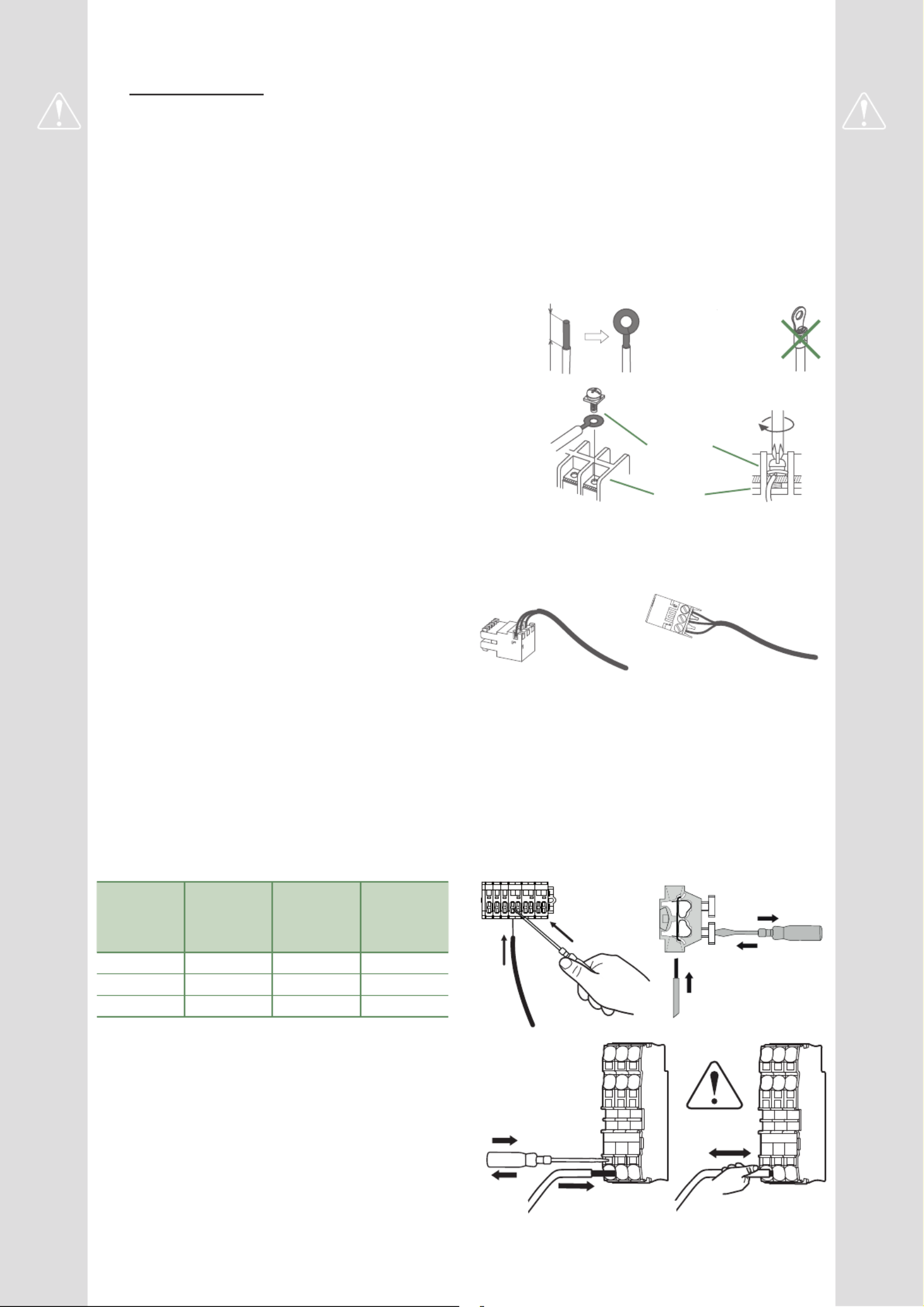
• Connecting to screw terminals
The use of ring, spade or blade terminals or
caps is prohibited.
- Always select wire that complies with current
standards.
- Strip wire end around 25 mm.
- With round end pliers, form a loop with a diameter
which matches the tightening screws on the
terminal.
- Tighten the terminal screw fi rmly onto the
loop created. Insuffi cient tightening can cause
overheating, leading to breakdown or even fi re.
Rigid wire Loop
25 mm Spade or blade
terminal on
fl exible wire is
prohibited
Screw
and
special washer
Terminal
• Connecting to controller boards
- Remove the corresponding connector and make
the connection.
Pre-cabled bundle connector and/or screw connector
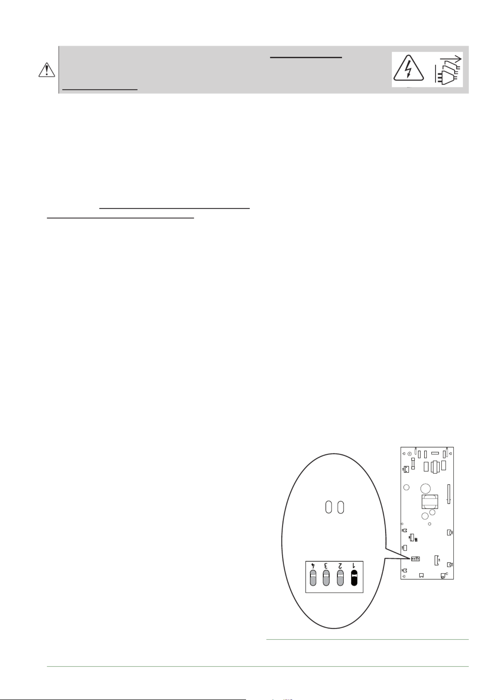
• Connecting to spring terminals
- Strip wire end around 12 mm.
- Push the spring with a screwdriver so that the wire
enters the cage.
- Slide the wire into the opening provided for this
purpose.
- Remove the screwdriver and then check that the
wire stays gripped by the cage by pulling on it.
2
1
3
1
3
2
4
(* according option)

- 4 -
This appliance must be installed by qualifi ed personnel holding a certifi cate of competence in the
handling of refrigerants.
Contents
Description of the equipment 6
Packing . . . . . . . . . . . . . . . . . . . . . . . . . . . . . . . . . 6
Unpacking and supplies . . . . . . . . . . . . . . . . . . . . 6
Defi nitions . . . . . . . . . . . . . . . . . . . . . . . . . . . . . . . 6
Optional equipment . . . . . . . . . . . . . . . . . . . . . . . . 6
Operating Range . . . . . . . . . . . . . . . . . . . . . . . . . . 6
General characteristics . . . . . . . . . . . . . . . . . . . . . 7
Description . . . . . . . . . . . . . . . . . . . . . . . . . . . . . 12
Operating principle . . . . . . . . . . . . . . . . . . . . . . . 14
Installation 16
Installation of refrigeration connections . . . . . . . . 16
Installation of the outdoor unit . . . . . . . . . . . . . . . 17
Installation of the hydraulic unit . . . . . . . . . . . . . . 20
Refrigeration connections 26
Rules and precautions . . . . . . . . . . . . . . . . . . . . . 26
Shaping the refrigeration pipes . . . . . . . . . . . . . . 27
Checks and connection . . . . . . . . . . . . . . . . . . . . 29
Filling with gas . . . . . . . . . . . . . . . . . . . . . . . . . . . 29
Hydraulic connections 32
Heating circuit . . . . . . . . . . . . . . . . . . . . . . . . . . . 32
DHW circuit . . . . . . . . . . . . . . . . . . . . . . . . . . . . . 33
Filling and bleeding the installation . . . . . . . . . . . 33
Electrical connections 34
Cable dimensions and protection rating . . . . . . . 35
Outdoor unit . . . . . . . . . . . . . . . . . . . . . . . . . . . . . 36
Hydraulic unit . . . . . . . . . . . . . . . . . . . . . . . . . . . . 37
Outside sensor . . . . . . . . . . . . . . . . . . . . . . . . . . 38
Room sensor (option) . . . . . . . . . . . . . . . . . . . . . 38
Controller Interface 40
User interface, central ambient unit (option) and
ambient sensor (option) . . . . . . . . . . . . . . . . . . . . 40 Description of the display . . . . . . . . . . . . . . . . . . 42
Temperature control 44
Setting . . . . . . . . . . . . . . . . . . . . . . . . . . . . . . . . . 44
Commissioning 46
PWM pump speed . . . . . . . . . . . . . . . . . . . . . . . . 46
Silent mode . . . . . . . . . . . . . . . . . . . . . . . . . . . . . 46
Confi guring room thermostat (wireless)(option) . 47
Confi guring room control unit (wireless) (option) . 47
Controller Menu 48
List of function lines . . . . . . . . . . . . . . . . . . . . . . . 49 Information display . . . . . . . . . . . . . . . . . . . . . . . 64
Fault Diagnosis 66
Faults in the Hydraulic Unit . . . . . . . . . . . . . . . . . 66
PWM circulator signals . . . . . . . . . . . . . . . . . . . . 67
Faults in the outdoor unit . . . . . . . . . . . . . . . . . . . 68
Waterstage Split Comfort DHW Serie / INSTALLATION / 2130 - EN
- 5 -
Maintenance of the installation 70
Hydraulic checks . . . . . . . . . . . . . . . . . . . . . . . . . 70
Maintenance of the DHW tank . . . . . . . . . . . . . . 70
Outdoor unit checks . . . . . . . . . . . . . . . . . . . . . . 70
Electrical circuit checks . . . . . . . . . . . . . . . . . . . . 70
Other maintenance 71
Emptying the hydraulic unit . . . . . . . . . . . . . . . . . 71
Distribution valve . . . . . . . . . . . . . . . . . . . . . . . . . 71
ACI check . . . . . . . . . . . . . . . . . . . . . . . . . . . . . . 71
Appendix 72
Filling the installation with gas . . . . . . . . . . . . . . . 72
Basic Hydraulic Layouts . . . . . . . . . . . . . . . . . . . 74
Electrical Cabling Plans . . . . . . . . . . . . . . . . . . . . 76
Designation of terminals of the control board . . . 79
Designation of terminals on the expansion card . 79
Quick-start procedure 80
Start-up check-list . . . . . . . . . . . . . . . . . . . . . . . . 80
Settings sheet . . . . . . . . . . . . . . . . . . . . . . . . . . . 82
Commissioning technical datasheet . . . . . . . . . . 83
Instructions for the end user 84
►
Symbols and defi nitions
Warning. Risk of serious injury to the person and
/ or risk of damage to the machine. Observe the
warning.
Important information that must always be kept in
mind.
Tips and tricks / Advice
Bad practice
Warning : Electricity hazard
Warning : Slightly fl ammable refrigerant
Read the installation manual
Read the Operating Manual
Read the instructions
This document was written in French and translated.
Read the document comprising the precautions for use (regulation installation and maintenance
conditions) before installation and/or use.
Waterstage Split Comfort DHW Serie / INSTALLATION / 2130 - EN
- 6 -
Description of the equipment
►
Packing
• Outdoor unit.1 package:
• 1 package: Hydraulic unit and outside temperature
sensor.
►
Defi nitions
- Split: The heat pump consists of two elements
(an outdoor unit to be installed outdoors and a hydraulic
unit to be installed inside the dwelling).
- Air/water: The surrounding air is the energy source.
This energy is transmitted to the heating circuit water
by the heat pump.
- Inverter: The fan and compressor speeds are
modulated according to the heating requirements.
This technology enables you to save on energy and
operate on a single-phase power supply, whatever
the heat pump’s output, by avoiding pulling signifi cant
amounts of current at start-up.
- COP (Coeffi cient of Performance): This is the
relationship between the energy transmitted to the
heating circuit and consumed electrical energy.
►
Optional equipment
• 2nd circuit kit (code UTW-KZDXE)
for connecting 2 heating circuits.
• Regulation extension kit (code UTW-KREXD)
to manage a 2nd heating circuit, telephone modem
etc...
• 6 kW backup relay kit (code UTW-KBHXL)
for switching to HP electrical backup of 3 to 6 kW.
• Boiler connection kit (code UTW-KBDXD)
for connecting a boiler to the heat pump.
• Room thermostat (code UTW-C55XA),
Wireless room thermostat (code UTW-C58XD)
for correcting the ambient temperature.
• Remote control (code UTW-C74TXF or UTW-C74HXF),
for correcting the ambient temperature and
programming the heat pump.
• Cooling kit (code UTW-KCLXL).
• DHW expansion kit (code UTW-KDEXL).
►
Operating Range
This heat pump provides:
- Heating in winter,
- The management of electrical backups, for extra
heating on the coldest days,
or
- Installation with boiler connection* for extra heating on
the coldest days,
- Management of two heating circuits*,
- Production of domestic hot water.
- Cooling in summer* (for underfl oor heating-cooling
system or fan-convectors).
* : According options / require the use of additional kits
(see chapter “Required accessory” or “Optional equipment”).
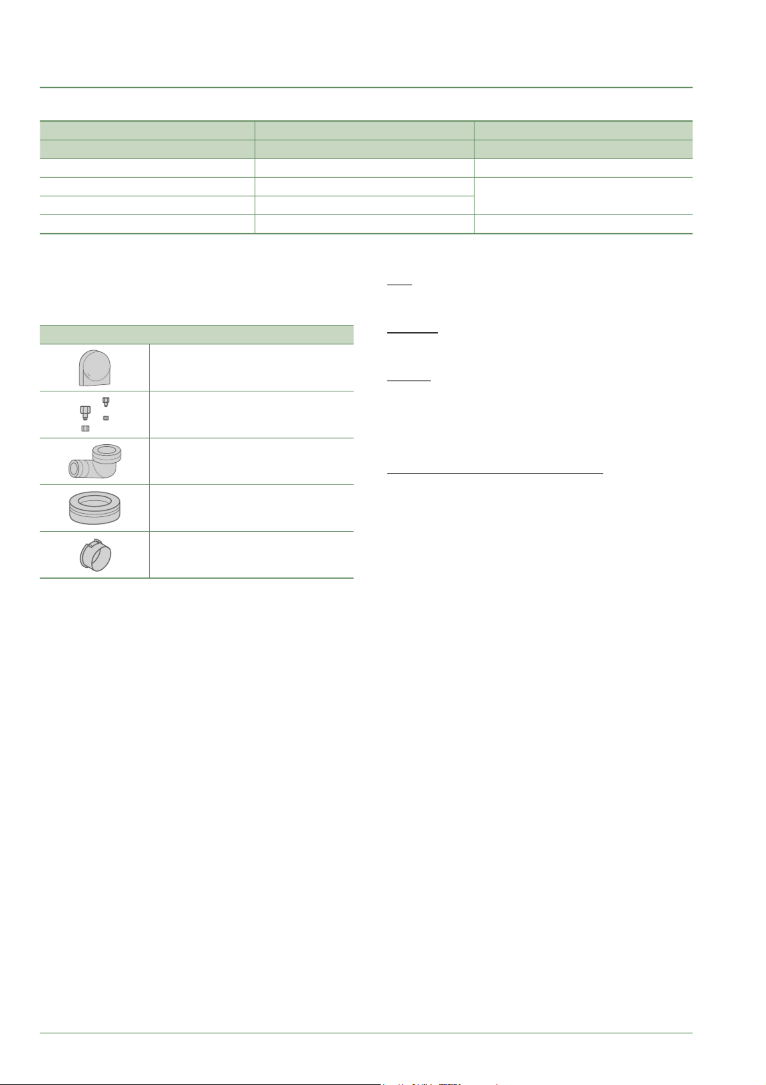
Accessories
Outdoor temperature sensor
Adapter 1/2”-5/8” and/or 1/4”-3/8” (1)
Nut 1/2” and/or 1/4” (1)
Elbow (2)
Plug (2) X 3
Cable grommet (2) X2
1 Only models 5 / 6 and 8
2 Only models 10
Waterstage Split Comfort DHW Serie / INSTALLATION / 2130 - EN
Packing contents list
Heat Pump Outdoor unit Hydraulic unit
Model Reference Reference
Waterstage Comfort 5 WOHA060KLT WGHA050ML3
Waterstage Comfort 6 WOHA060KLT WGHA080ML3
Waterstage Comfort 8 WOHA080KLT
Waterstage Comfort 10 WOHA100KLT WGHA100ML3

- 7 -
►
General characteristics
1 Hydraulic unit: Sound pressure level at (x) m from the appliance,
1.5m off the ground, open fi eld directionality 2 / Outdoor unit : Sound
pressure level at (x) m from the device, halfway between the ground
and top of the outdoor unit, open fi eld directionality 2.
2 The sound power level is a laboratory measurement of the emitted
sound power. It does not correspond to a measurement of the
perceived sound power.
3 Refrigerant R32 as per NF EN 378.1 standard.
4 Filling with refrigerant R32 is done at the factory.
5 Taking into account a possible additional fi ll of refrigerant R32
(see "Additional fi lling", page 30).
6 The announced thermal and acoustic performances are measured
with 7.5m length refrigerant lines.
Model 5 6 8 10
Rated heating performances (outdoor temp. / fl ow temp.)
Heat output
+7°C / +35°C - Underfl oor heating system kW 4.50 5.50 7.50 9.5
+7°C / +55°C - Radiator kW 4.50 5.50 7.00 9
Power absorbed
+7°C / +35°C - Underfl oor heating system kW 0.949 1.18 1.69 2.11
+7°C / +55°C - Radiator kW 1.70 2.06 2.63 3.33
Coeffi cient of Performance (COP) (+7 °C / + 35 °C) 4.74 4.65 4.43 4.5
Electrical specifi cations
Electrical voltage (50 Hz) V 230 230 230 230
Maximum current for appliance A 13 13 18 19
Maximum current of the Heating system electrical backup (according option)
A 13 (26.1) 13 (26.1) 13 (26.1) 13 (26.1)
Power of the Heating system electrical backup (according option)
kW 3 (6 kW option available)
Circulation pump actual power consumption W 22 22 22 38
Maximum power consumed by the outdoor unit W 3260 3260 4510 4760
DHW electrical backup power W 1500 1500 1500 1500
Hydraulic Circuit
Maximum operating pressure heating / hot water tank MPa (bar)
0.3 (3) / 1 (10) 0.3 (3) / 1 (10) 0.3 (3) / 1 (10) 0.3 (3) / 1 (10)
Flow rate of the hydraulic circuit for Δt=4°C (rated conditions) l/h 970 1185 1616 2047
Flow rate of the hydraulic circuit for Δt=8°C (rated conditions) l/h 485 593 808 1024
Miscellaneous
Weight of outdoor unit Kg 39 39 42 62
Noise level at 5 m
1 (outdoor unit) dB (A) 35 35 38 40
Sound power level in accordance with EN 12102
2
(outdoor unit)
dB (A) 57 57 60 62
Weight of hydraulic unit (empty / full of water) Kg 145 / 359 145 / 359 145 / 359 145 / 359
Water capacity of the hydraulic unit / hot water tank l 24 / 190 24 / 190 24 / 190 24 / 190
Noise level at 1 m
1 (hydraulic unit) dB (A) 32 32 32 32
Sound power level in accordance with EN 12102
2 (hydraulic unit)
dB (A) 40 40 40 40
Heating system operating limits
Outdoor temperature min/max °C -20 / +35 -20 / +35 -20 / +35 -20 / +35
Max. heating water fl ow temperature underfl oor heating °C 45 45 45 45
Max. heating water fl ow temperature low temperature radiator °C 52 52 52 52
Refrigeration circuit
Gas pipe diameters Inches 1/2 1/2 1/2 5/8
Liquid Piping Diameters Inches 1/4 1/4 1/4 3/8
Factory fi ll of refrigerant R32
3g 970 970 1020 1630
Maximum operating pressure MPa (bar) 4.2 (42) 4.2 (42) 4.2 (42) 4.2 (42)
Minimum / Maximum length of pipes
4 / 6 m 3 / 15 3 / 15 3 / 15 3 / 20
Maximum length of pipes
5 / Maximum level diff erence m 30 / 20 30 / 20 30 / 20 30 / 20
Waterstage Split Comfort DHW Serie / INSTALLATION / 2130 - EN
- 8 -
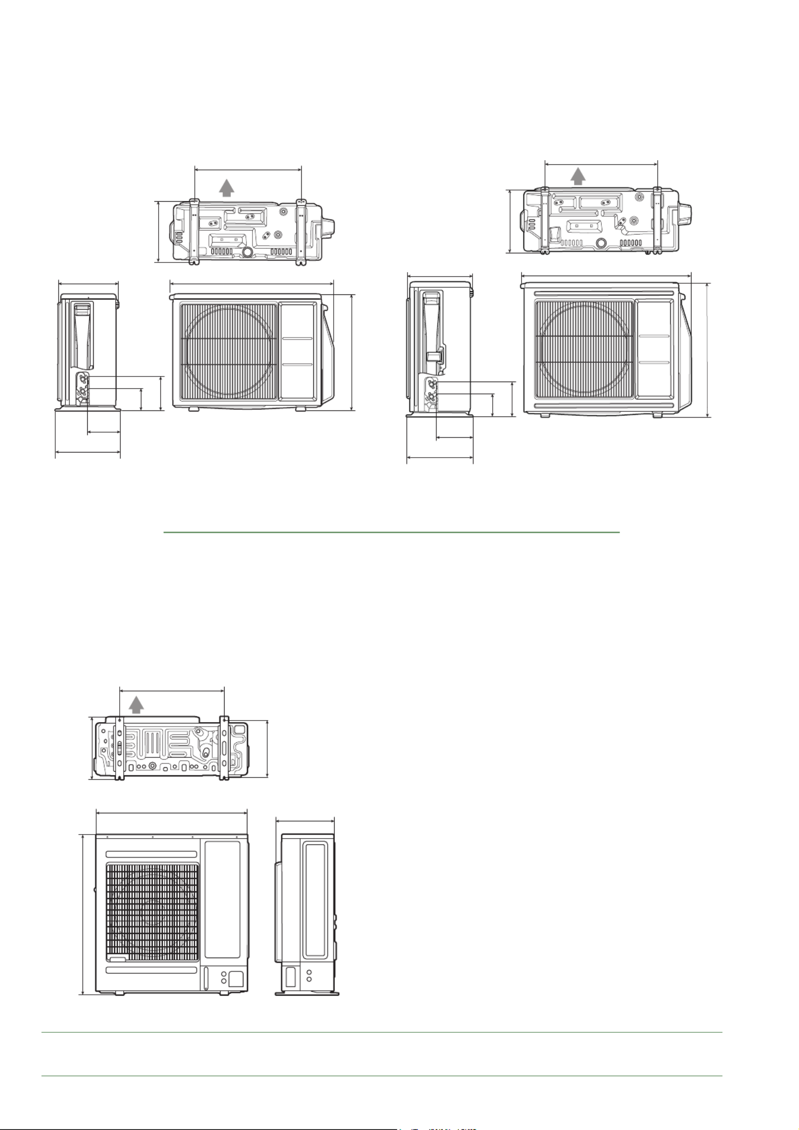
886324
353
180
580
330
632
120
184
Air
907349
353
194
600
330
716
119
184
Air
fi g. 1 - Dimensions in mm
■Outdoor unit Model 5 & 6 ■Outdoor unit Model 8
■Outdoor unit Model 10
998
940 365
390
650
355
Air
Waterstage Split Comfort DHW Serie / INSTALLATION / 2130 - EN
- 9 -
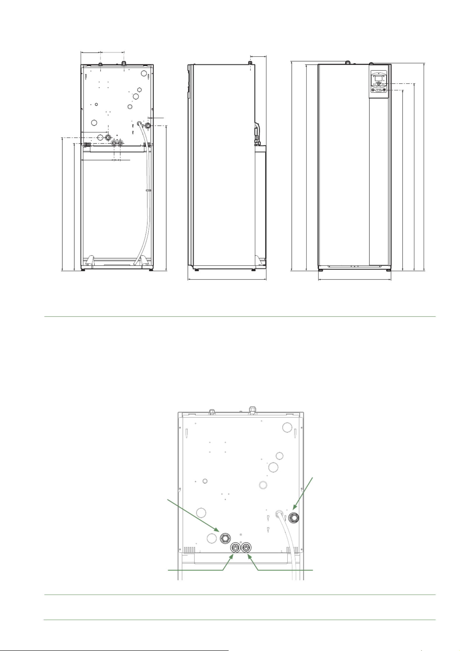
648
297
244
47
175
1855
1841
1863
1615
1673
144
700
1295
55
1189
1137
210
fi g. 2 - Dimensions in mm
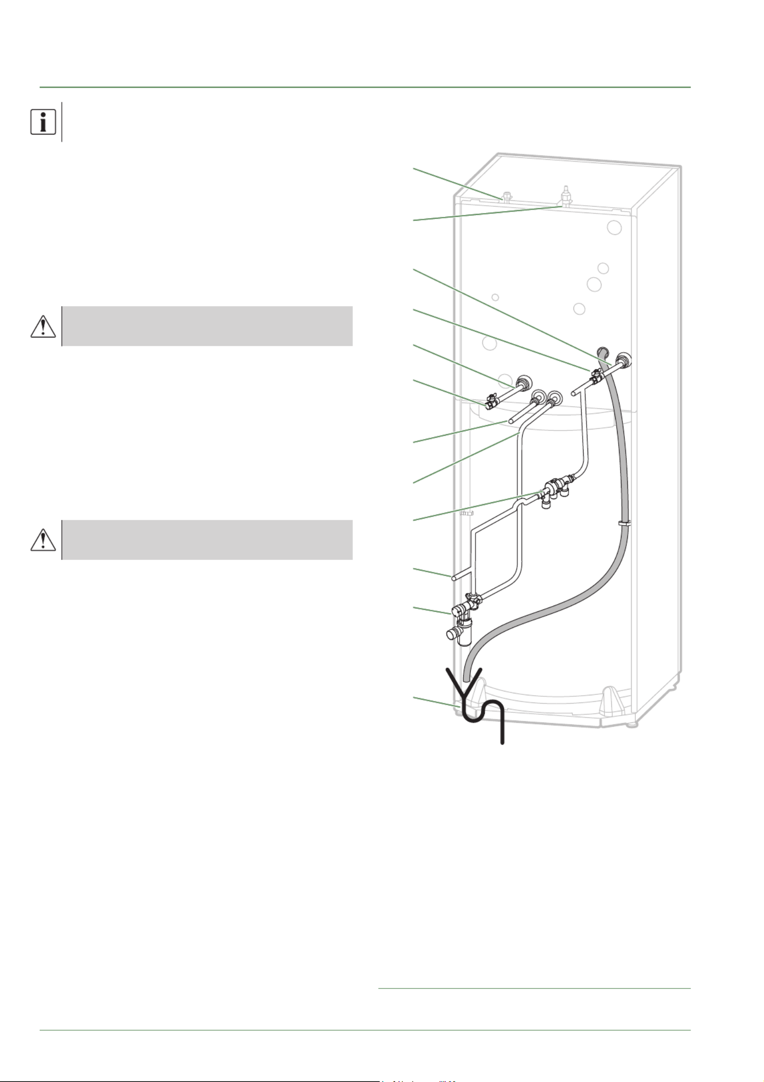
fi g. 3 - Hydraulic connections
Space requirements of the hydraulic unit, see fi g. 19, page 20.
Back view
Back view
Side view Front view
■Hydraulic unit
Heating outlet
Ø 26x34 1” male
DHW
Ø 20x27 3/4” male
DCW
Ø 20x27 3/4” male
Heating inlet
Ø 26x34 1” male
Waterstage Split Comfort DHW Serie / INSTALLATION / 2130 - EN
- 10 -
-50
1000
10000
43907
2490
338
-25 0 25 50 75
° C
°C
0
2500
5000
7500
10000
12500
15000
17500
20000
22500
25000
27500
30000
32500
0 10 20 30 40 50 60 70 80 90 100
B3977
Outside sensor QAC34
Heat Pump return sensor
Heat Pump fl ow sensor
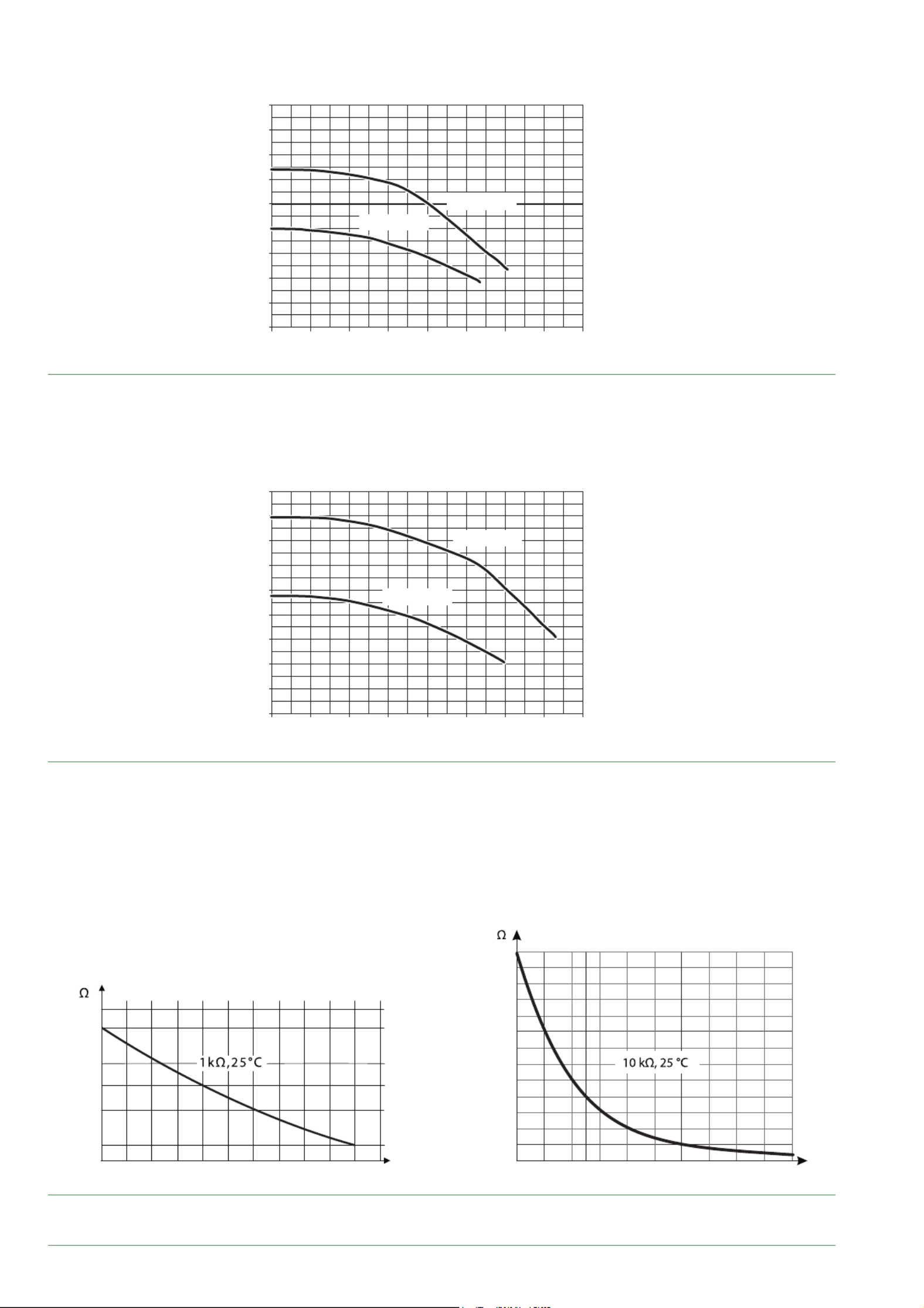
fi g. 4 - Available hydraulic pressures and fl ow rates (models 5, 6 and 8)
fi g. 5 - Available hydraulic pressures and fl ow rates (model 10)
fi g. 6 - Ohmic sensor values (Hydraulic unit)
0
0
1
2
3
4
5
6
7
8
9
0.2 0.4 0.6 0.8 1 1.2 1.4 1.6
m3/h
mCE (1 mbar = 10 mmCE = 100 Pa)
PWM 100%
PWM 75%
0
0
1
2
3
4
5
6
7
8
9
0.2 0.4 0.6 0.8 1 1.2 1.4 1.6
m3/h
mCE (1 mbar = 10 mmCE = 100 Pa)
PWM 75%
PWM 100%
Waterstage Split Comfort DHW Serie / INSTALLATION / 2130 - EN
- 11 -
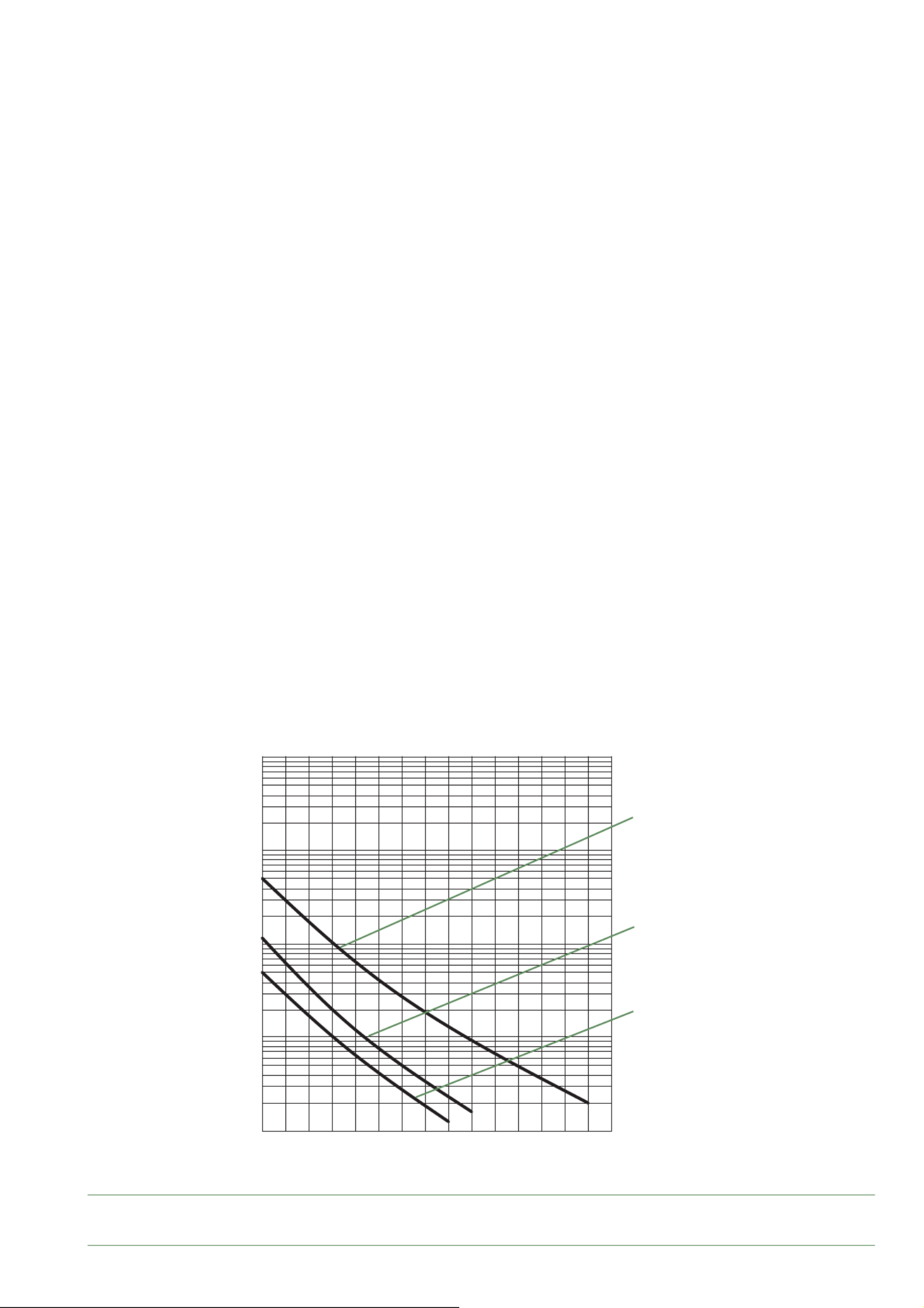
fi g. 7 - Ohmic sensor values (Outdoor unit)
-20 -10 0 10 20 30 40 50 60 70 80 90 100 110 120 130
10000
1000
100
10
1
- Compressor
- Discharge
- Condensation
- Expansion valve
- Evaporator inlet
- Outdoor unit
Temperature °C
Ohmic value (k )Ω
Waterstage Split Comfort DHW Serie / INSTALLATION / 2130 - EN
- 12 -
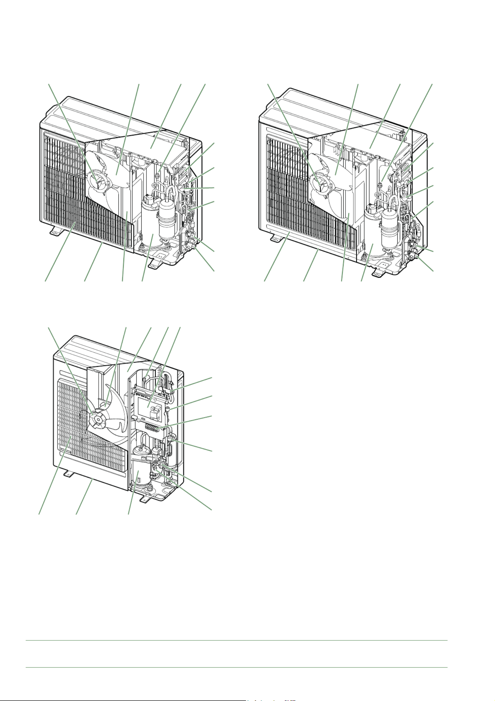
►
Description
Key :
1. High performance and low noise impeller.
2. Electrical motor with variable "Inverter" operation.
3. "Inverter" control unit.
4. Connection terminal blocks
(power supply and interconnection).
6. 4-way valve.
7. Anti-corrosion treated bodywork.
8. Main circuit electronic expansion valve.
9. Noise and thermally insulated "Inverter" compressor.
10. Refrigeration connection valves (fl ared connectors) with
protective caps (a: liquid; b: gas).
11. Holding tank with condensate drain hole.
12. High-performance exchange surface evaporator; anti-
corrosion treated hydrophilic aluminium fi ns and grooved
copper tubes.
13. Pressure Switch
14. Pressure sensor
■Outdoor unit Model 5 & 6 ■Outdoor unit Model 8
■Outdoor unit Model 10
fi g. 8 - Outdoor unit components
2 1 3
4
6
8
10a
10b
912117
13
14
2 1 3
4
6
8
10a
10b
912117
13
14
1 2
7 11 9
12 13 3
6
14
4
8
10b
10a
Waterstage Split Comfort DHW Serie / INSTALLATION / 2130 - EN
- 13 -
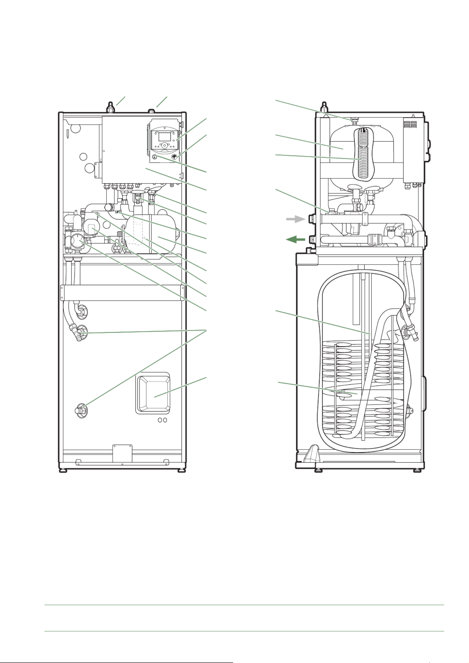
fi g. 9 - Hydraulic unit components
Key :
1. Electric control box.
2. Controller / User interface.
3. ON/OFF Switch.
4. Hydraulic unit circulation pump.
5. Distribution valve.
6. "Gas" refrigeration connection.
7. "Liquid" refrigeration connection.
8. Condensation sensor.
9. Drain valve.
10. Safety valve.
11. Safety thermostat.
12. Pressure gauge.
13. Automatic bleeder valve.
14. Expansion vessel.
15. Condenser.
16. Heat Pump electrical backup.
17. Domestic Hot Water electrical backup.
Sensors :
20. Heat Pump return sensor.
21. Domestic Hot Water sensor.
22. Heat Pump fl ow sensor.
■Hydraulic unit
12
3
110
4
9
8
14
22
13
5
17
21
16
11
9
2
15
13
6 7
20
Waterstage Split Comfort DHW Serie / INSTALLATION / 2130 - EN
- 14 -
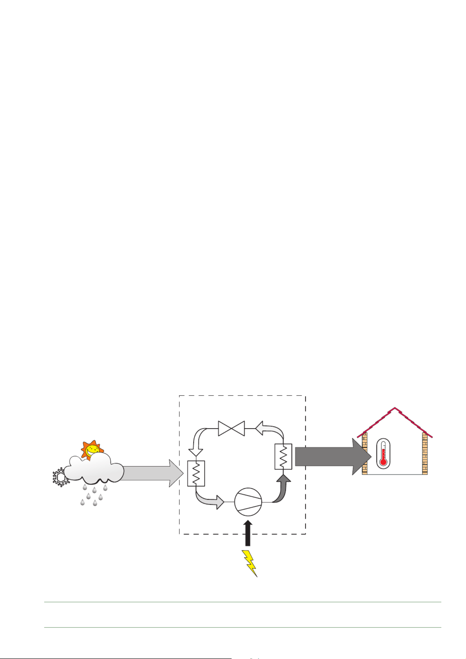
►
Operating principle
The heat pump transmits the energy contained in the
surrounding air into the dwelling to be heated.
The heat pump consists of four main elements, in which
a refrigerant (R32) circulates
- In the evaporator (ref. 12, fi g. 8, page 12) :
The calories are taken from the outside air and
transmitted to the refrigerant. Because it has a low
boiling point, it changes from a liquid to a vapour, even
in cold weather (down to -25°C outside temperature).
- In the compressor (ref. 9, fi g. 8, page 12) :
The vaporised refrigerant is pressurised and takes on
even more calories.
- In the condenser (ref. 15, fi g. 9, page 13) :
The energy of the refrigerant is transmitted to the
heating circuit. The refrigerant returns to its liquid state.
- In the expansion valve (ref. 8, fi g. 8, page 12) :
The liquefi ed refrigerant is returned to a low pressure
and regains its initial temperature and pressure.
The heat pump is equipped with a controller which
controls the room temperature based on the outdoor
temperature measurement. The room thermostat
(option) provides a corrective action for the temperature
control.
The hydraulic unit is fi tted with an electrical backup* or
boiler connection* which intervenes to provide additional
heat during the coldest periods.
■Control functions
- The heating circuit's fl ow temperature is controlled by
the temperature control.
- Depending on the heating fl ow temperature,
the outdoor unit's power is modulated by the "Inverter"
compressor.
- Control of the backup electrical heating.
- The daily timer program is used to set the periods
where the ambient temperature is comfortable or
reduced.
- Summer/winter time mode switchover is automatic.
- Management of the boiler backup*.
- Room sensor*: The room sensor provides a corrective
action for the temperature control.
- Control of a second heating circuit*.
- Domestic hot water: Heating timer program.
- Managing cooling*.
* Where the heat pump is fi tted with options and associated kits.
■Protective functions
- Anti-legionella cycle for domestic hot water.
- Anti-corrosion tank protection with titanium anode
(ACI).
- Frost protection: Frost protection cuts in if the heating
circuit's fl ow temperature falls below 5°C (provided
that the heat pump's electrical power supply is not
interrupted).
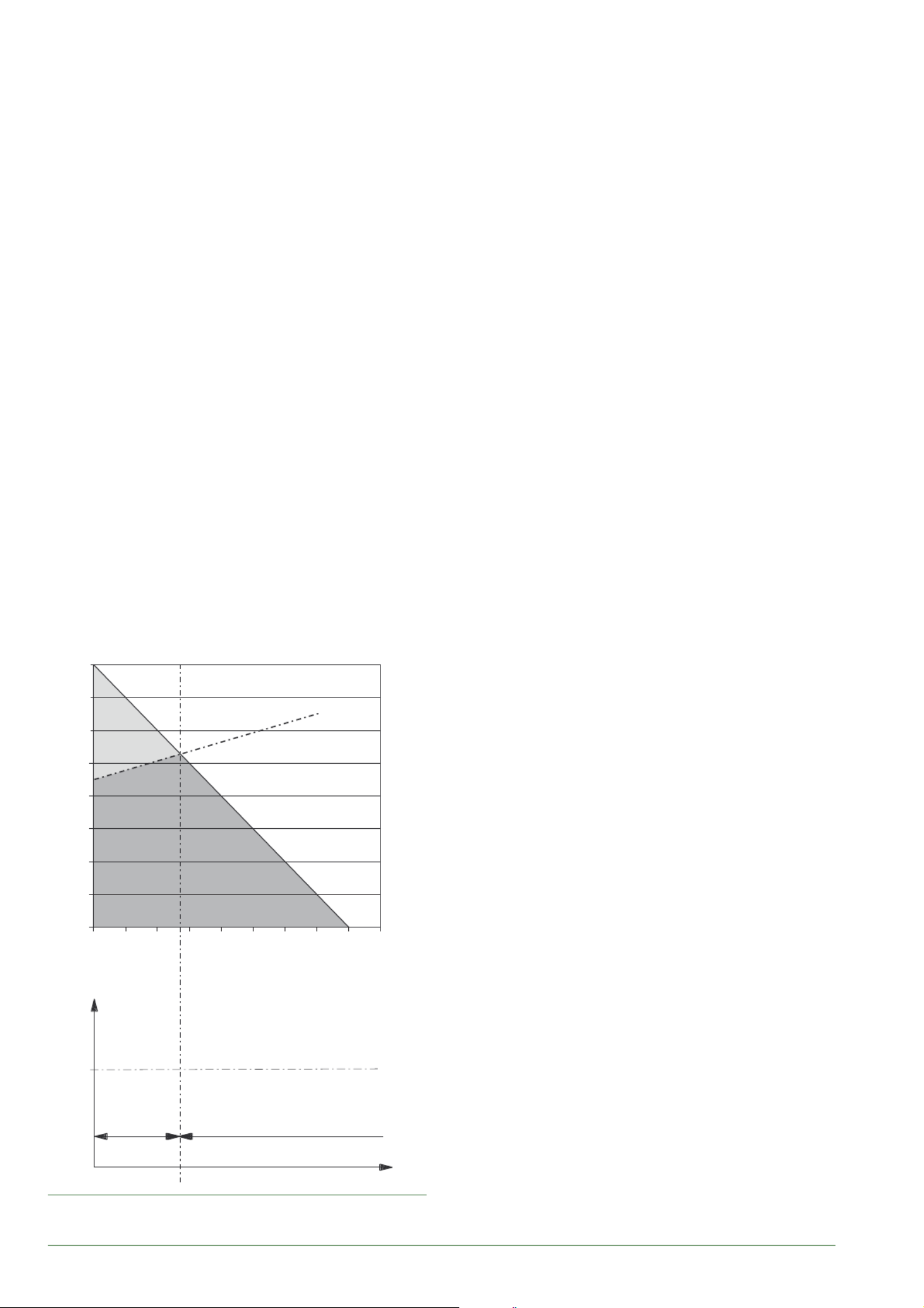
fi g. 10 - Examples and operating limits
8
7
6
5
4
3
2
1
0
-20 -15 -10 -5 0 5 10 15 20 25
46
Dwelling heat loss (kW)
Outdoor temperature (°C)
Outdoor temperature (°C)
Heat Pump power
Max authorised
Heat Pump start-up temp.
Water return temperature (°C)
Heat Pump only
Heat Pump
Heat Pump +
electrical
backup
Backup
Waterstage Split Comfort DHW Serie / INSTALLATION / 2130 - EN
- 15 -
■Domestic hot water (DHW) operating principle
Two domestic hot water (DHW) temperatures can be
set: comfort and reduced.
The default DHW program is set to the comfort
temperature between 00:00 and 05:00 and between
14:30 and 17:00 and to the reduced temperature for the
rest of the day. This optimises electrical consumption
while ensuring comfortable water temperatures.
The reduced temperature setpoint may be useful to
avoid restarting the DHW too often and for too long
during the day.
The production of domestic hot water (DHW) is started
when the temperature in the tank drops to 7°C below
the temperature setpoint.
The heat pump produces the domestic hot water, which
is then additionally heated, if required, by the tank's
electrical backup or by the boiler. To ensure a DHW
setpoint over 55°C, the electrical backup heating must
be left on.
If the contract signed with the energy provider includes
a day/night tariff , the electrical backup is subject to the
supplier’s power tariff and the comfort temperature may
only be reached at night.
If no particular contract has been signed, the comfort
temperature can be reached at any time, including
during the day.
The production of DHW takes priority over heating;
nevertheless the production of DHW is managed
by cycles that regulate the amount of time assigned
to heating and production of DHW in the event of
simultaneous demand.
Anti-legionella cycles can be programmed.
■Fan convectors with integrated control system
Do not use a room sensor in the area in question.
fi g. 11 - Heat pump operating principle
Ev
Dt
Cn
Cp
1 kW
COP 4
4 kW
20 °C
PAC
PAC - Heating Pump
Ev - Evaporator
Cp - Compressor
Cn - Capacitor
Dt - Expansion Valve
Air energy
Heat produced
Electrical
energy
consumed
Waterstage Split Comfort DHW Serie / INSTALLATION / 2130 - EN
- 16 -
Installation
►
Installation of refrigeration connections
Bend the pipes into position and make holes
for them through the fl oor or walls either with
their protective caps in place or after brazing.
Keep the protective caps in place or ends
brazed until the appliance is commissioned.
The outdoor unit must be connected to the
hydraulic unit ONLY with brand new separately
insulated copper connections (refrigerant quality).
Maintain the same pipe diameters (fi g. 32).
Observe the maximum and minimum distances
between the hydraulic unit and the outdoor unit
(fi g. 32, page 28) the guarantee of performance and
the service lifespan of the system depend on this.
The minimum length of the refrigeration
connections for correct operation is 3 m.
The appliance's warranty will be void if it is operated
with refrigeration connections less than 3 m long
(tolerance +/- 10%).
Ensure that the refrigeration connections are protected
from physical deterioration.
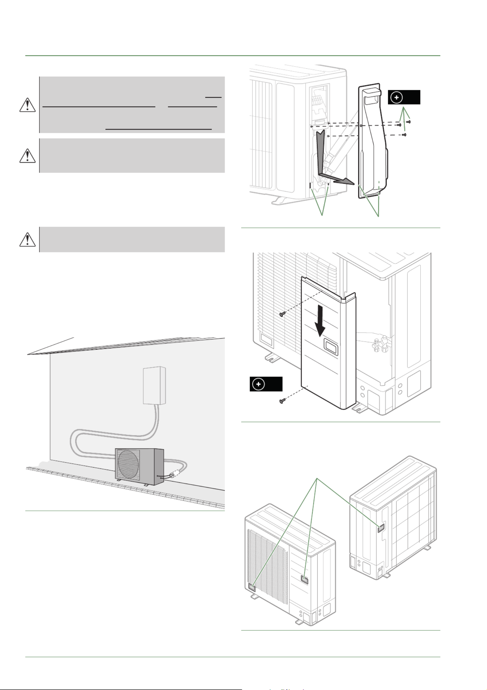
fi g. 12 - Example of recommendation for layout of
refrigeration connections
fi g. 13 - Open the outdoor unit model 5, 6 & 8
X3
Holes Hooks
fi g. 14 - Open the outdoor unit model 10
fi g. 15 - Transport of the outdoor unit model 10
X2
handles
Waterstage Split Comfort DHW Serie / INSTALLATION / 2130 - EN
- 17 -
►
Installation of the outdoor unit
▼
Installation precautions
The outdoor unit must only be installed
outside. If a shelter is required, it must have
broad openings on all 4 sides and installation
clearances must be observed.
• Choose the location of the appliance after discussion
with the client.
• We recommend choosing a site that is sunny but
sheltered from strong cold prevailing winds.
• The unit must be easily accessible for future installation
and maintenance work ( g. 16 and g. 17, page 18).
• Ensure that connections to the hydraulic unit can be
made easily.
• The outdoor unit is able to withstand bad weather but
avoid installing it in a position where it is likely to be
exposed to signi cant dirt or owing water (e.g. under
a broken gutter).
• Water may ow out of the outdoor unit when it is
operating. Do not install the outdoor unit on a paved
terrace; choose a well-drained location (e.g. gravel or
sand). If installation is carried out in an area where the
temperature stays below 0°C for long periods, check
that the presence of ice does not present any danger.
A drain pipe can also be connected to the condensate
drain pan (optional) ( g. 18, page 19).
• Nothing should obstruct the air circulation through the
evaporator and out from the fan ( g. 16 and g. 17,
page 18).
• Keep the outdoor unit away from heat sources and
ammable products.
• Make sure that the unit does not disturb the
surrounding area or inhabitants (noise level, draught,
low temperature of the ejected air freezing the plants
in its path.
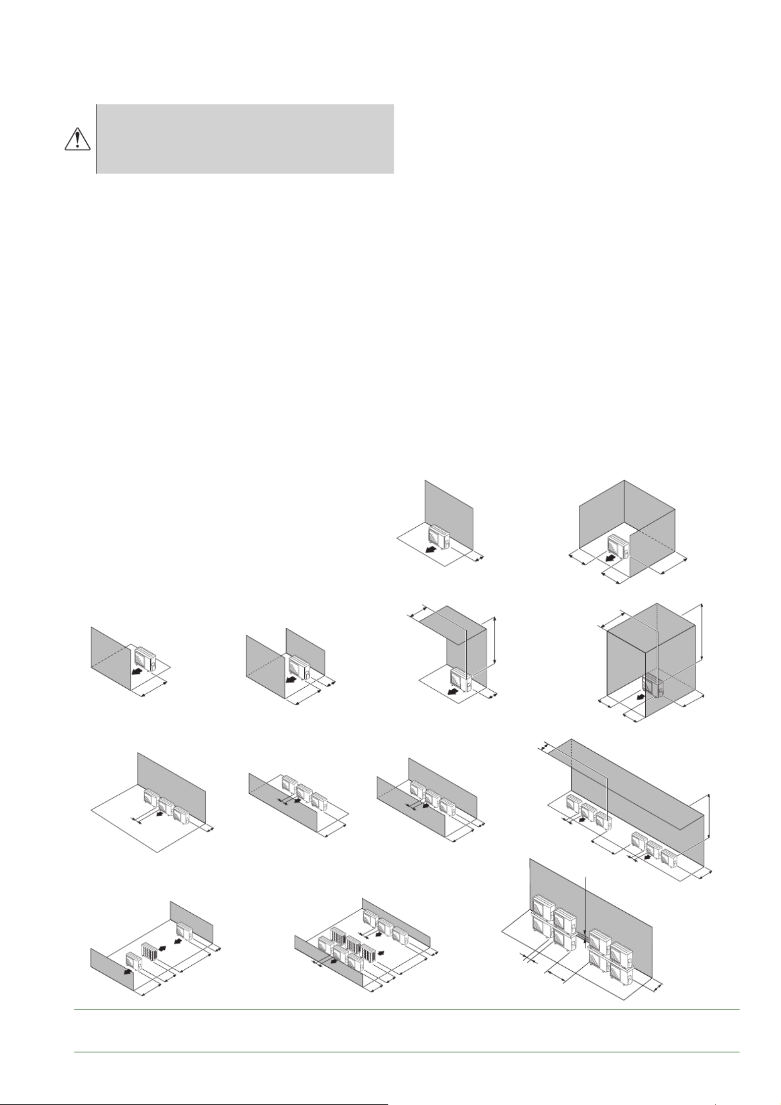
g. 16 - Minimum installation clearances around the outdoor unit (model 5, 6 & 8)
A
C
A
A
GG
A
A
L
G
G
C
A
L
A
B
CH
C
B
H
C
J
B
C
C
M
J
A
B
F
HB
E
H
C
K
C
B
H
B
C
A 100 mm
B 200 mm
C 250 mm
D 300 mm
E 400 mm
F 500 mm
G 600 mm
H 1000 mm
J 1500 mm
K 2000 mm
L = 200 mm max
M = 300 mm max
■ Models 5, 6 & 8
Waterstage Split Comfort DHW Serie / INSTALLATION / 2130 - EN
- 18 -
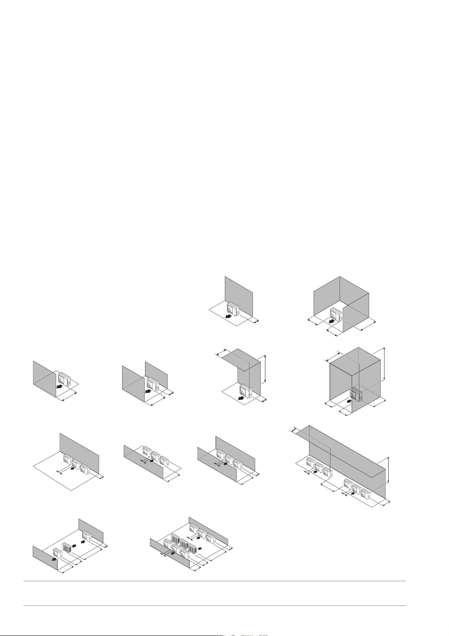
g. 17 - Minimum installation clearances around the outdoor unit (model 10)
A
D
A
A
FF
A
E
N
H
H
D
F
N
C
E
DJ
D
F
J
D
J
F
D
D
M
J
B
G
J
KF
G
J
D
L
D
A 100 mm
B 150 mm
C 200 mm
D 250 mm
E 300 mm
F 500 mm
G 600 mm
H 1000 mm
J 1500 mm
K 3000 mm
L 3500 mm
M = 300 mm max
N = 500 mm max
■Model 10
Waterstage Split Comfort DHW Serie / INSTALLATION / 2130 - EN
- 19 -
H
H
B BC
• The surface on which the appliance is installed must:
- Be permeable (soil, gravel, etc.).
- Be perfectly fl at,
- Support its weight easily.
- Allow a solid fastening base,
- Not transmit any vibration to the dwelling. Anti-vibratory
blocks are available as an option.
• The wall bracket cannot be used where it is likely to
transmit vibrations. Installing the unit on the ground is
preferred.
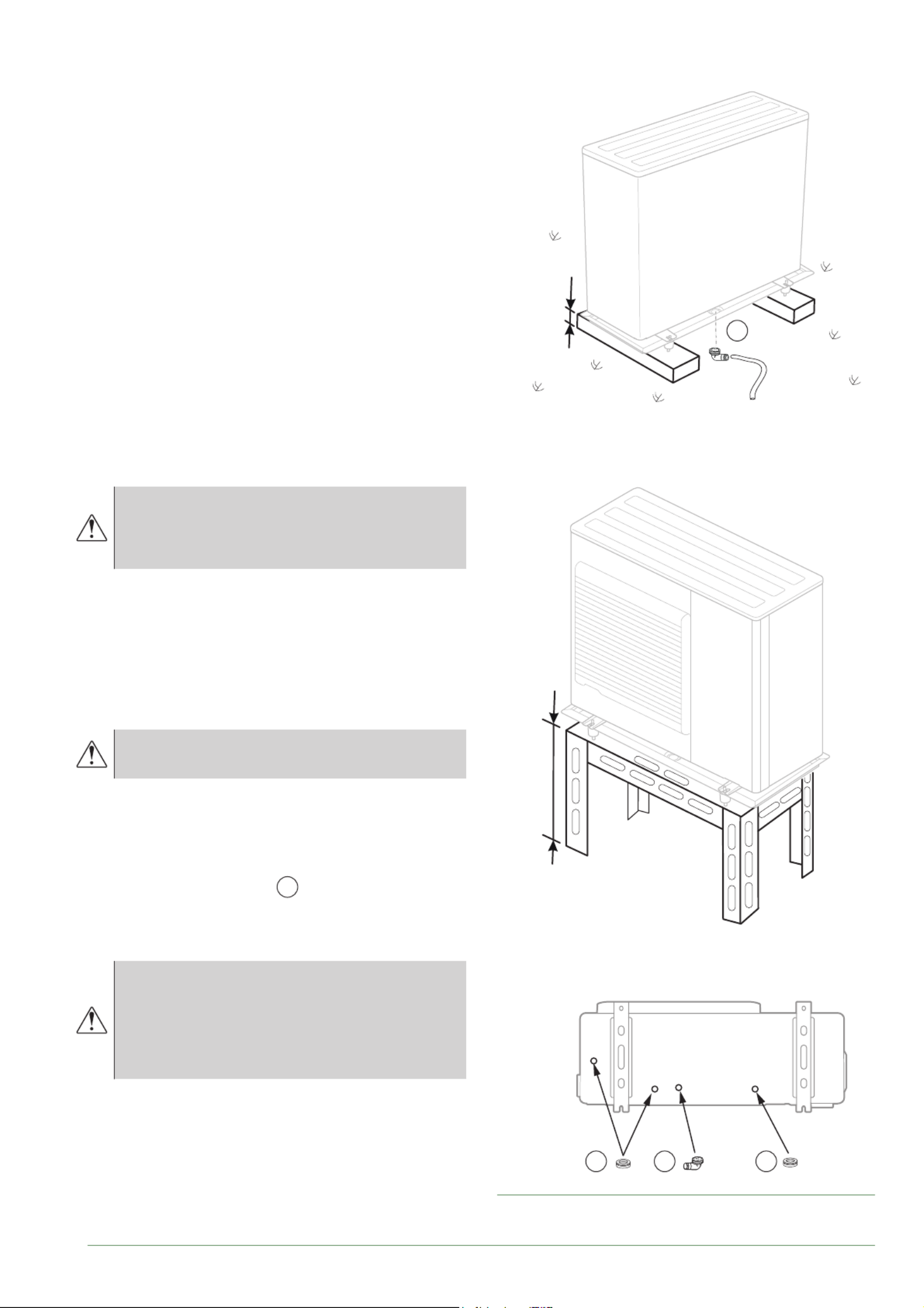
▼
Positioning Outdoor Unit
The outdoor unit must be raised at least 50 mm above
ground level. In areas prone to snow, this height should
be increased but should not exceed 1.5 m
- Fasten the outdoor unit by means of screws and
rubber tightening or toothed lock washers to prevent
them from coming loose.
In areas with heavy snowfall, if the inlet and
outlet of the outdoor unit are blocked with
snow, heating may become diffi cult and a
failure is likely to occur.
Construct a canopy or place the unit on a high stand
(local confi guration).
- Place the unit on a solid stand in order to minimise
impacts and vibrations.
- Do not place the unit directly on the ground as this will
cause problems.
▼
Condensate drain pipe
The outdoor unit can generate a large volume
of water (called condensate).
If the use of a drain pipe is necessary (e.g., superposition
of the outdoor units) :
- Install the condensate drain pan (optional) for models
5, 6 & 8 only. Use the elbow provided and connect ©
a 16 mm-diameter hose for draining the condensate.
- Use the plug(s) provided B to block the opening of
the condensate drain pan (model 10).
Allow for the condensate to fl ow away under the force of
gravity (waste water, rain water, gravel bed).
If installation is carried out in an area where the
temperature stays below 0°C for long periods,
equip the drain pipe with trace heating to
avoid it icing up. Trace heating must heat not
only the drain pipe but also the bottom of the
appliance's condensate collection tank.
* In areas with heavy snowfall,
(H) must be higher than the average snow layer.
fi g. 18 - Installation of the outdoor unit
evacuation of condensates
Model 10 only
C
Waterstage Split Comfort DHW Serie / INSTALLATION / 2130 - EN
- 20 -
►
Installation of the hydraulic unit
Heat sources such as :
- Open fl ame,
- High temperature surface >700°C (fi lament),
- unsealed contactor >5kVA,
Avoid using sources of heat inside the room where
the heat pump is installed. If this is not possible,
see page 24
▼
Installation precautions
• Choose the location of the appliance after discussion
with the client.
• The installation space should comply with current
regulations.
• To facilitate maintenance and allow access to the
various parts, we recommend that you provide
suffi cient space all the way around the hydraulic unit
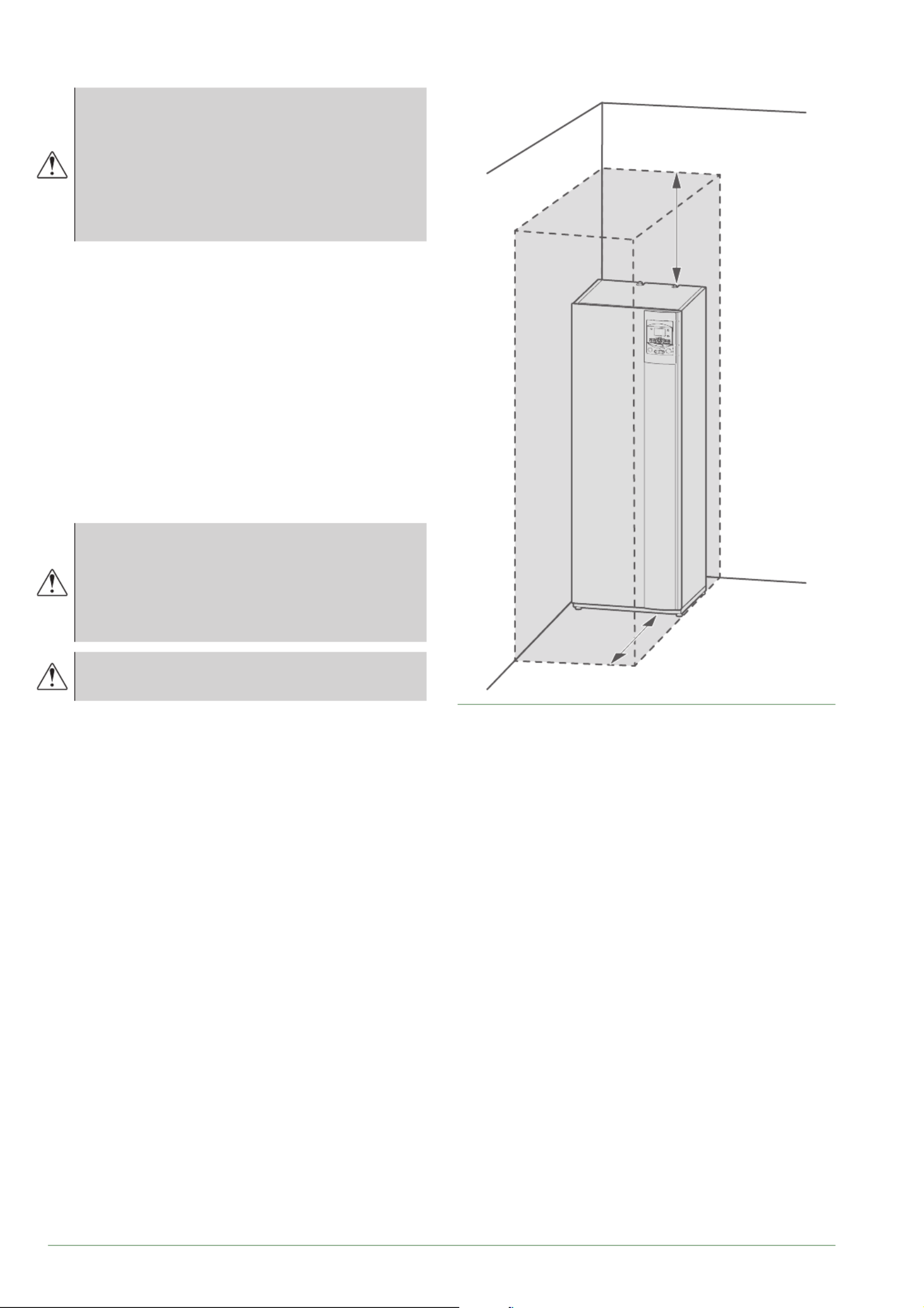
(fi g. 19).
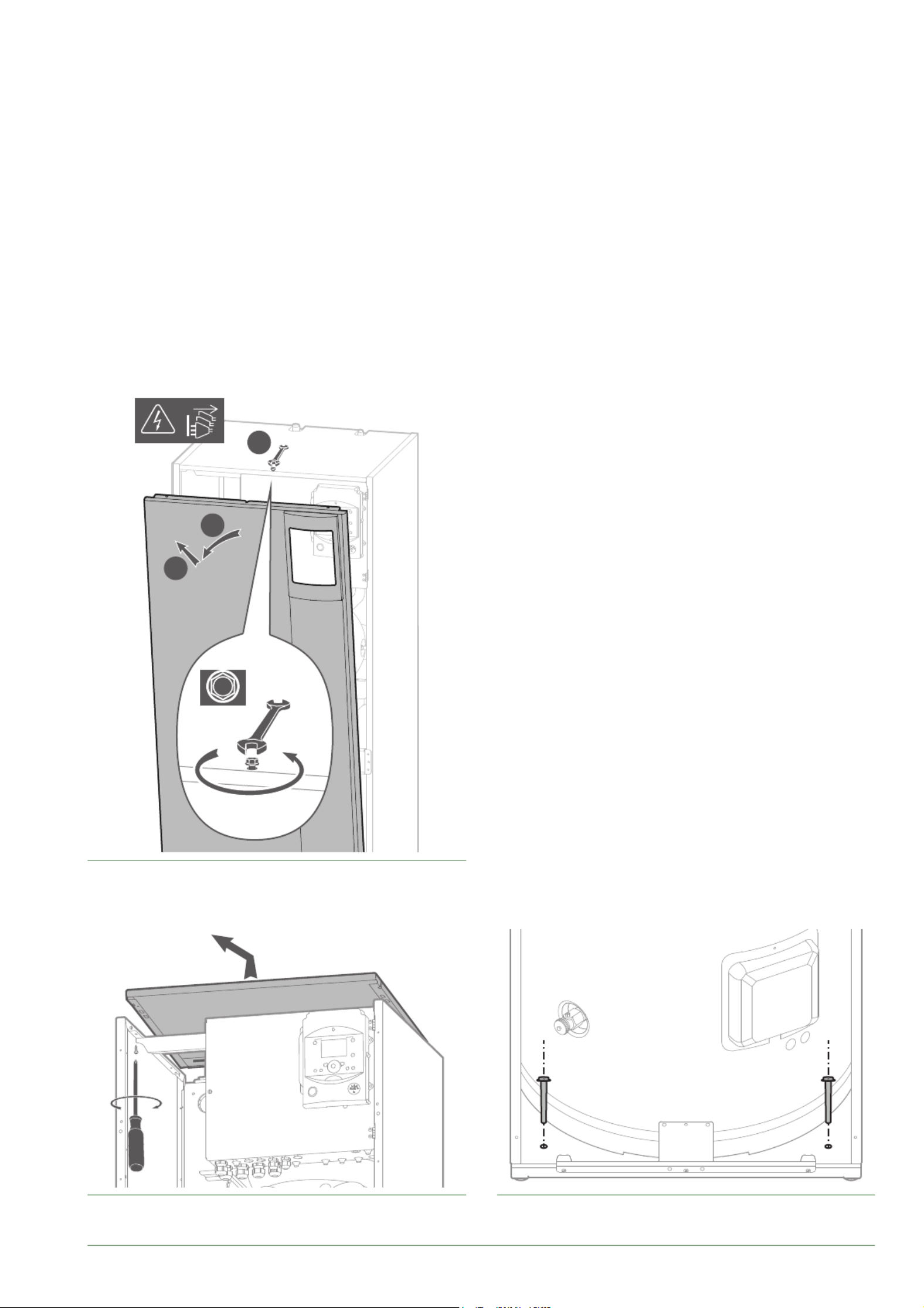
• Fix the hydraulic module to the ground (fi g. 22)
(fi xing system not supplied).
Other cautions
Be careful not to bring fl ammable gas
near the heat pump during installation,
in particular when brazing is required.
The appliances are not fi reproof and should
not therefore be installed in an explosive
environment.
To prevent risks of humidity in the exchanger,
it is pressurized with nitrogen.
- To avoid condensation inside the condenser, remove
the refrigeration circuit caps only when making the
refrigeration connections.
- If the refrigeration connection is only performed at the
end of the installation, make sure that the refrigeration
circuit caps* remain in place and tight throughout the
installation.
* (Hydraulic unit side and outdoor unit side).
- After each maintenance operation on the refrigeration
circuit and before the fi nal connection, take care to
put the caps back in position to avoid any pollution
of the refrigeration circuit (sealing with adhesive is
prohibited).
fi g. 19 - Minimum installation clearances around the
hydraulic unit
300
1000
Waterstage Split Comfort DHW Serie / INSTALLATION / 2130 - EN
- 21 -
fi g. 20 - Open the front cover
1
2
3
8
fi g. 21 - Removing the cover fi g. 22 - Floor fi xing
Waterstage Split Comfort DHW Serie / INSTALLATION / 2130 - EN
- 23 -
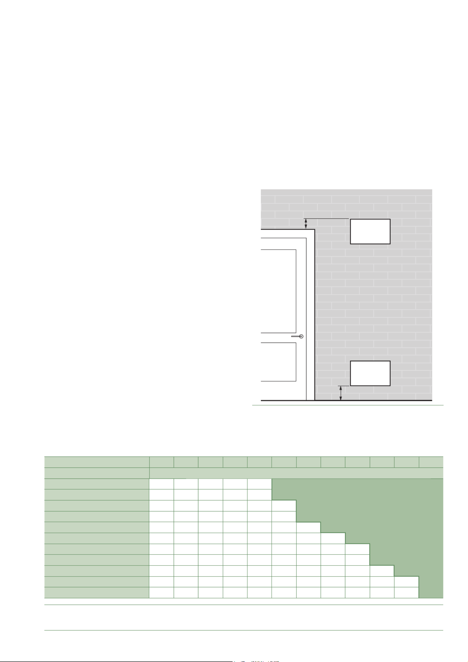
fi g. 24 - Section of the opening
Room volume (m3) 1.0 1.5 2.0 2.5 3.0 3.5 4.0 4.5 5.0 5.5 6.0 6.5
Refrigerant Amount (g) Minimal section (S) of the opening (cm
2)
970 500 350 250 200 200
1000 550 350 300 250 200
1100 600 400 300 250 200 200 No requirement
1170 600 400 300 250 200 200
1300 700 450 350 300 250 200 200
1400 750 500 400 300 250 250 200 200
1500 800 550 400 350 300 250 200 200 200
1600 850 550 450 350 300 250 250 200 200
1700 900 600 450 350 300 250 250 200 200 200
1800 950 650 500 400 350 300 250 250 200 200 200
1840 950 650 500 400 350 300 250 250 200 200 200
fi g. 25 - Position of openings for ventilation
200max
S
S
Waterstage Split Comfort DHW Serie / INSTALLATION / 2130 - EN
- 24 -
▼
With Heat sources
Heat sources such as :
- Open fl ame,
- High temperature surface >700°C (fi lament),
- unsealed contactor >5kVA,
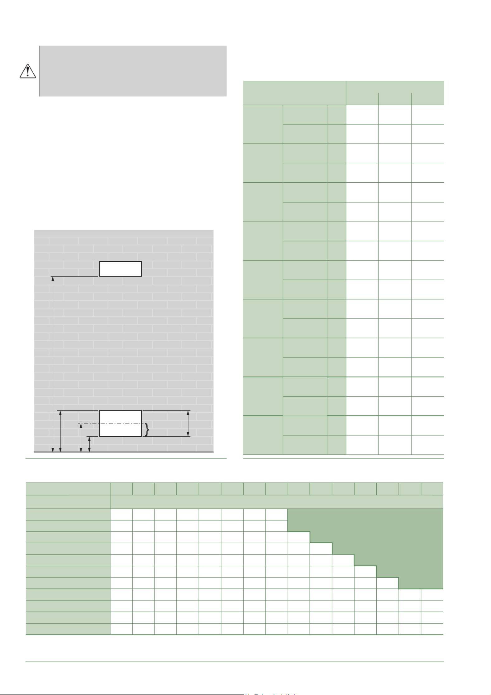
In accordance with IEC 60-335-2-40 standard, the
hydraulic module of the heat pump as well as all the
refrigerant connections that cross the inhabited area
must be installed in rooms respecting the minimum
surface (fi g. 27).
Depending on the total coolant load (heat pump + links
+ additional load):
if the minimal surface area (fi g. 27) cannot be complied
with, follow the instructions in fi g. 29 to take into
account the surface areas of adjoining rooms and the
creation of ventilation points (see fi g. 26 and fi g. 28).
fi g. 26 - Position of openings for ventilation
>1500
300max
200
20mini
100max
50% Smin
Smin >50% Smin
fi g. 27 - Minimum room surface
fi g. 28 - Minimal section of the opening
Refrigeration connections
Length
Modele (kW)
5, 6 8 10
15 m
R32 gas
charge g 970 1020 1630
min room
Surface m23.83 4.03 6.73
16 m
R32 gas
charge g 995 1045 1630
min room
Surface m23.93 4.13 6.73
17 m
R32 gas
charge g 1020 1070 1630
min room
Surface m24.03 4.22 6.73
20 m
R32 gas
charge g 1095 1145 1630
min room
Surface m24.32 4.52 6.73
21 m
R32 gas
charge g 1120 1170 1650
min room
Surface m24.42 4.62 6.89
22 m
R32 gas
charge g 1145 1195 1670
min room
Surface m24.52 4.72 7.06
23 m
R32 gas
charge g 1170 1220 1690
min room
Surface m24.62 4.82 7.23
25 m
R32 gas
charge g 1220 1270 1730
min room
Surface m24.82 5.01 7.58
30 m
R32 gas
charge g 1345 1395 1830
min room
Surface m25.31 5.51 8.48
Surface of Room (mA2) 0.8 1.0 1.5 2.0 2.5 3.0 3.5 4.0 4.5 5.0 5.5 6.0 6.5 7.0 7.5
Refrigerant Amount (g) Minimal section (Smin) of the low opening (cm
2)
970 246 232 196 160 124 88 51 15
1000 256 241 205 169 133 97 61 25
No requirement
1100 287 273 236 200 164 128 92 56 20
1170 309 294 258 222 186 150 114 78 42 6
1300 350 335 299 263 227 191 155 119 83 47 11
1400 381 367 330 294 258 222 186 150 114 78 42 6
1500 412 398 362 326 290 254 218 181 145 109 73 37 14
1600 444 429 393 357 321 285 249 213 177 141 105 68 46 29 12
1700 475 461 424 388 352 316 280 244 208 172 136 100 77 61 45
1800 506 492 456 420 384 348 312 275 239 203 167 131 109 93 78
1840 519 504 468 432 396 360 324 288 252 216 180 144 122 106 91
Waterstage Split Comfort DHW Serie / INSTALLATION / 2130 - EN
- 25 -
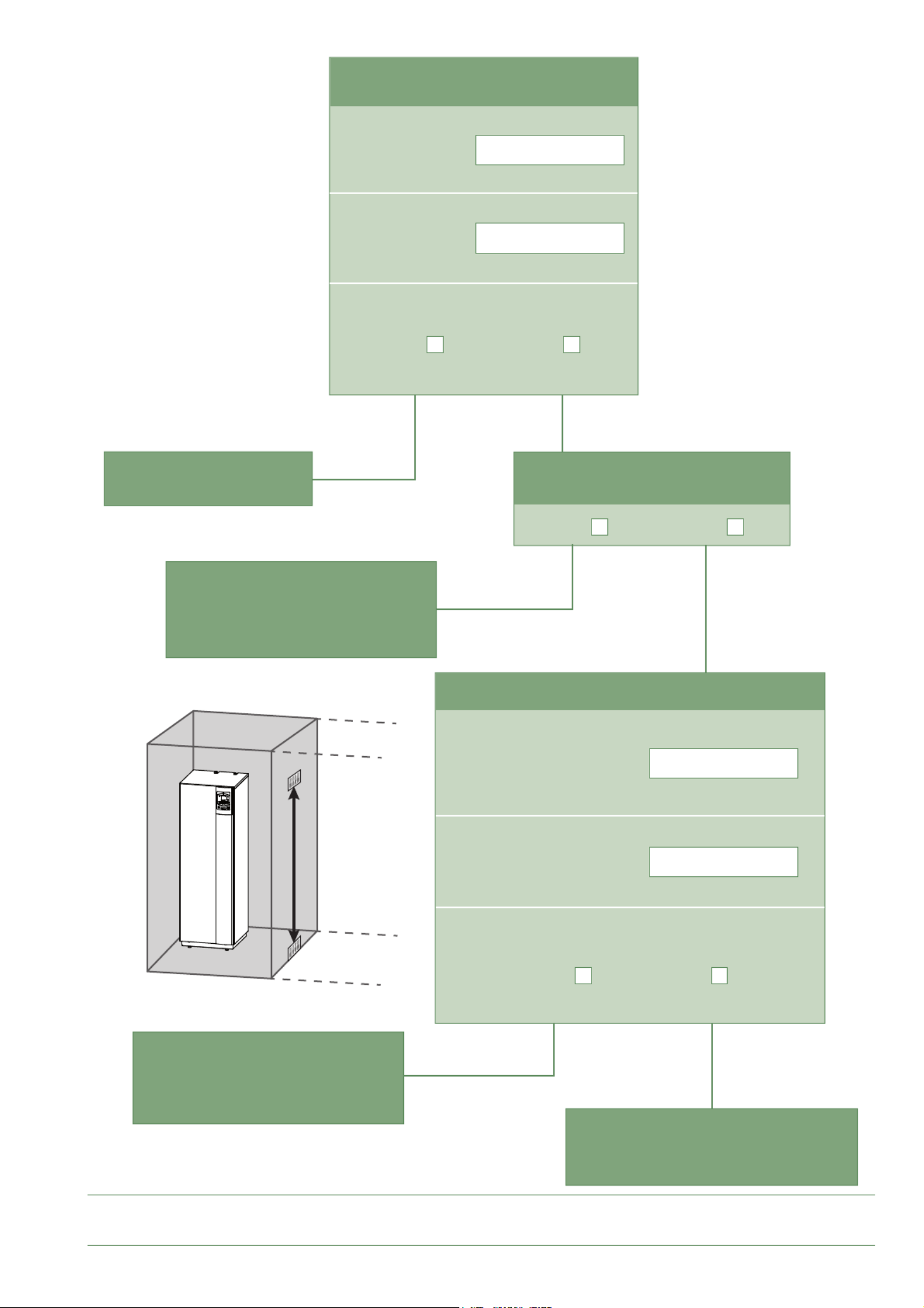
fi g. 29 - Minimum room surface
m2
m2
m2
m2
> 1500
AB
Min. room surface
See fi g. 27
Adjacent room surface
No requirement Indoor unit in an
unoccupied area
Create opening (Smin) for
natural ventilation to the
outside
See fi g. 26 & fi g. 28
Create opening (Smin) for
natural ventilation into
A B and room
See fi g. 26 & fi g. 28
Add a detector and
a mechanical ventilation
Yes
Yes
No
No
Yes
Yes
Yes
No
No
No
Yes
No
Room surface ( ) > Min. room surface ?A
Room surface ( + ) > Min. room surface ?A B
Min. room surface
Room surface ( )A
Adjacent room surface ( )B
Total surface ( + )A B
Waterstage Split Comfort DHW Serie / INSTALLATION / 2130 - EN
- 27 -
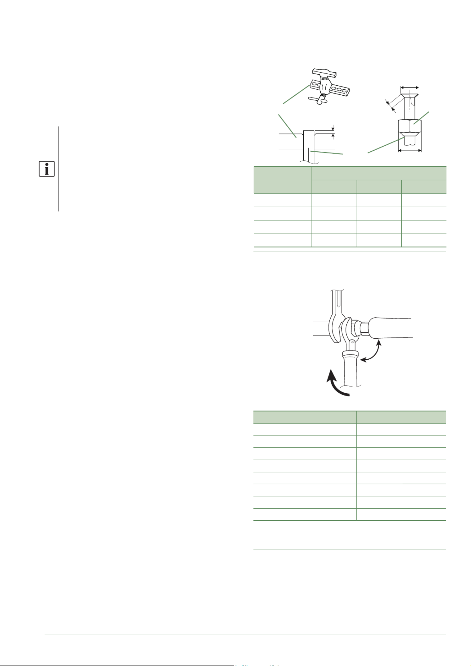
fi g. 30 - Flaring of the fl are connections
Flaring tool
Pipe
Nut
fl are
B
L
C
ø Pipe Dimensions in mm
L B 0/-0.4 C
6.35 (1/4") 1.8 to 2 9.1 17
9.52 (3/8") 2.5 to 2.7 13.2 22
12.7 (1/2") 2.6 to 2.9 16.6 26
15.88 (5/8") 2.9 to 3.1 19.7 29
►
Shaping the refrigeration pipes
▼
Bending
The refrigeration pipes must be shaped only on a
bending machine or with a bending spring in order to
avoid any risk of crushing or breaking them.
Remove the insulation material from the section of
pipe to be bent.
Do not bend copper to an angle greater than 90°.
The radius of curvature must be more than
2.5x ø pipe.
Never bend pipes more than 3 times in the same
place otherwise traces of fracturing may appear
(hardening of the metal).
▼
Creating the fl arings
- Cut the pipe to an appropriate length with a pipe-cutter
without damaging it.
- Carefully deburr it, holding the pipe pointing downward
to avoid introducing fi lings into the pipe.
- Remove the fl ared connection nut situated on the
valve to be connected and slide the pipe into the nut.
- Proceed to fl are it, letting the pipe protrude out of the
fl aring tool's tube.
- After fl aring, check the state of the working radius (L).
This must not present any scratches or signs of
fracturing. Also check the dimension ( ).B
90°
fi g. 31 - Tightening torques
Designation Tightening torque
Flared nut 6.35 mm (1/4") 16 to 18 Nm
Flared nut 9.52 mm (3/8") 32 to 42 Nm
Flared nut 12.7 mm (1/2") 49 to 61 Nm
Flared nut 15.88 mm (5/8") 63 to 75 Nm
Plug (A) 3/8", 1/4" 20 to 25 Nm
Plug (A) 1/2" 28 to 32 Nm
Plug (A) 5/8" 30 to 35 Nm
Plug (B) 3/8", 5/8", 1/2", 1/4" 12.5 to 16 Nm
Plug (A) & (B) : see fi g. 22, page 25.
Holding spanner
Torque wrench
Waterstage Split Comfort DHW Serie / INSTALLATION / 2130 - EN
- 29 -
►
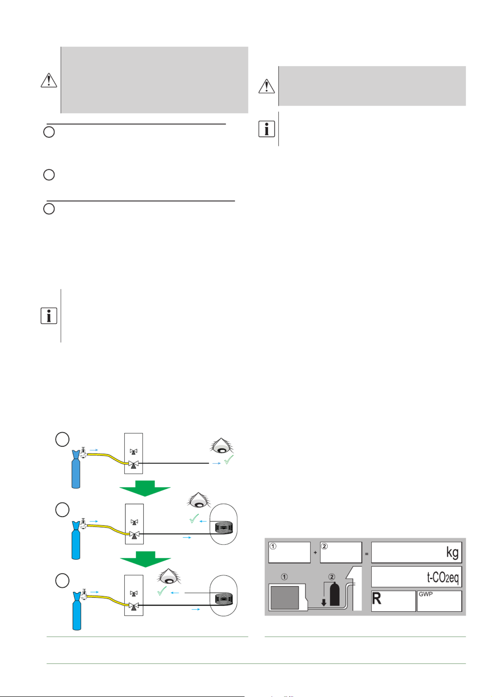
Checks and connection
The refrigeration circuit is very sensitive to dust
and humidity: check that the area around the
connection is clean and dry before removing the
plugs protecting the refrigeration connectors.
Indicated blowing value: 6 bar for minimum
30 seconds for connection of 20 m.
Checking the gas connection (large diameter)
1 Connect the gas connection to the outdoor unit. Blow
dry nitrogen into the gas connection and inspect its end::
- If water or impurities emerge, use a brand new
refrigeration connection.
2 Otherwise, proceed with fl aring and connect the
refrigeration connection to the outdoor unit immediately.
Checking the liquid connection (small diameter)
3 Connect the liquid connection to the hydraulic
unit. Blow nitrogen into the gas-condenser-liquid
connection system and inspect its end (outdoor unit
side).
- If water or impurities emerge, use a brand new
refrigeration connection.
- Otherwise, proceed with fl aring and connect the
refrigeration connection to the outdoor unit immediately.
Take particular care to position the tube
opposite its connector so as not to risk
damaging the threads. A properly aligned
connector can be attached easily by hand
without much force being required.
- Where necessary, connect an adapter (reducer)
1/4''- 3/8'' or 1/2''- 5/8'' (see fi g. 31, page 27)
- Comply with the indicated tightening torques.
(fi g. 31, page 27). If it is too tight, the fi tting may break
after a long period of time and cause a refrigerant leak.
►
Filling with gas
■see "Filling the installation with gas", page 72
Indicate on the label present on the outdoor
unit, the amount of gas (Factory + additional
fi lling) see fi g. 34.
If additional fi lling is required, do it before fi lling
the hydraulic unit with gas. Refer to paragraph
"Additional fi lling", page 30.
- Remove the access plugs (A) (fi g. 55, page 73)
from the valve controls.
- First of all fully open the liquid valve (small) and
then the gas valve (large) using an Allen (hex) key
(anti-clockwise direction) without using excessive
force against the stop.
- Quickly disconnect the hose from the .Manifold
- Refi t the 2 original caps (be sure they are clean) and
tighten them to the recommended tightening torque
indicated in the table fi g. 31, page 27. A seal is
achieved in the caps only with metal to metal.
The outdoor unit does not contain any additional
refrigerant allowing the installation to be bled.
Bleeding by fl ushing is strictly forbidden.
▼
Final sealing test
The sealing test must be carried out with a certifi ed gas
detector (sensitivity of 5g/year).
Once the refrigeration circuit has been gassed as
described above, check that all the refrigeration
connectors are gas-tight (4 connectors). If the fl arings
have been made correctly, there should be no leaks.
If necessary, check the seal of the refrigeration valve
caps.
If the event of a leak
- Return the gas to the outdoor unit (pump down).
The pressure should not drop below atmospheric
pressure (0 relative bar read on the ) so as not Manifold
to contaminate the recovered gas with air or moisture.
- Redo the connection,
- Restart the commissioning procedure.
fi g. 33 - Checking refrigeration connections fi g. 34 - Additional fi lling label
gaz
Azote
3
3
3
2
Azote
3
1
Nitrogen
Nitrogen
Nitrogen
Gas
connection
Gas
connection
Gas
Liquid
connection
OU
OU HU
HU
OU
Waterstage Split Comfort DHW Serie / INSTALLATION / 2130 - EN
- 30 -
▼
Additional fi lling
The amount needed to fi ll the outdoor units corresponds to the maximum distances between the outdoor unit and
the hydraulic unit as defi ned here page 28. If the distances are greater, an additional amount of R32 is required.
For each type of appliance, this additional amount depends on the distance between the outdoor unit and the
hydraulic unit. Any additional fi lling with R32 must be carried out by an approved specialist.
Model 5, 6, 8 (Outdoor unit WOYA060KLT, WOYA080KLT)
15m < Length of the connections 30m≤
(Length of the connections - 15m) x 25 g/m= g
Model / Factory fi ll Length of the
connections in m 16 17 X 29 30
Model 5, 6 / 970 g Fill amount in g 995 1020 970 + (X - 15) x 25 = g 1320 1345
Model 8 / 1020 g 1045 1070 1020 + (X - 15) x 25 = g 1370 1395
Model 10 (Outdoor unit WOYA100KLT)
20m < Length of the connections 30m≤
(Length of the connections - 20m) x 20 g/m= g
Model
... /
Factory
fi ll
Length of the
connections in m 21 22 X 29 30
Model 10 / 1630 g Fill amount in g 1650 1670 1630 + (X - 20) x 20
= g 1810 1830
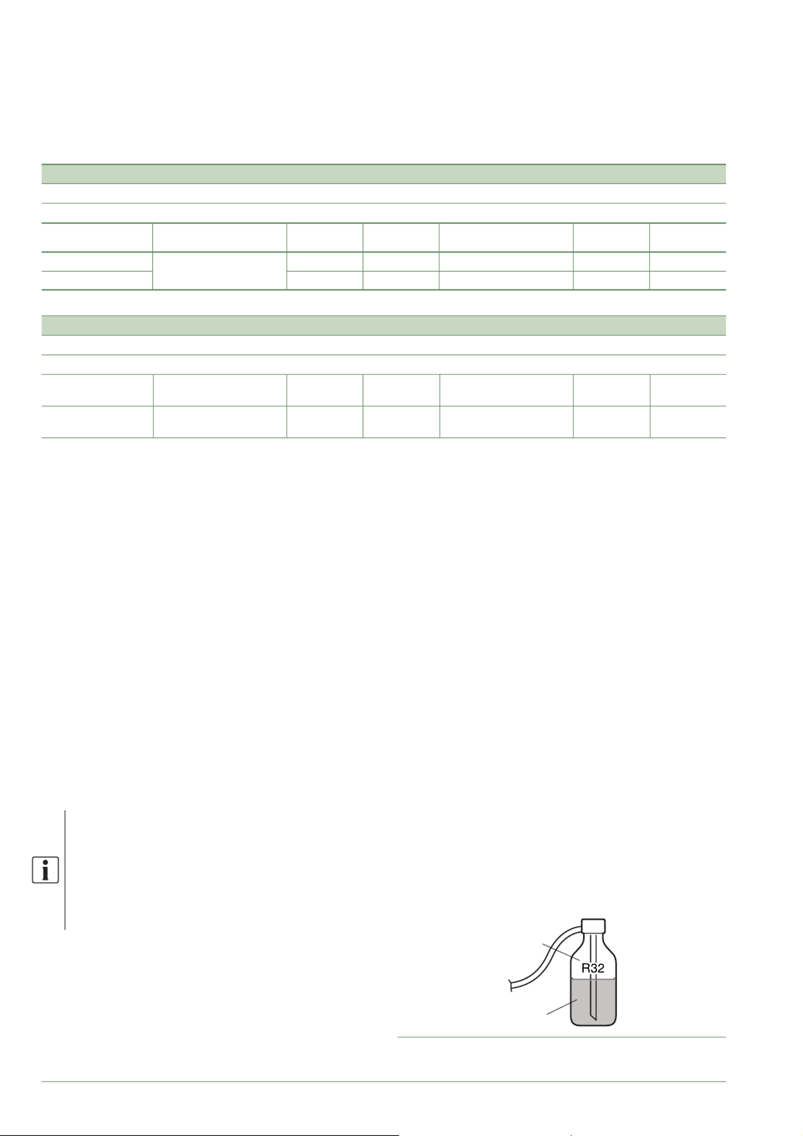
Filling must be carried out after creating a vacuum and
before gassing the hydraulic unit, as follows:
- Disconnect the vacuum pump (yellow hose) and
connect a bottle of R32 in its place in the liquid
extraction position.
- Open the bottle’s valve.
- Bleed the yellow hose by loosening it slightly on the
Manifold side.
- Place the bottle on scales with a minimum accuracy of
10g. Note the weight.
- Carefully open the blue valve slightly and check the
value shown on the scales.
- As soon as the value displayed has dropped by the
value for the calculated additional fi ll amount, close the
bottle and disconnect it.
- Quickly disconnect the hose connected to the
appliance.
- Proceed to fi ll the hydraulic unit with gas.
Only use R32 !
Only use tools suitable for R32
(set of pressure gauges).
Always fi ll in the liquid phase.
Never exceed the maximum length or
diff erence in level.
Liquid
Gas
fi g. 35 - Gas bottle R32
Waterstage Split Comfort DHW Serie / INSTALLATION / 2130 - EN
- 31 -
ON
DIP SW
Interface
Board
LED2
(Green)
LED1
(Red)
fi g. 36 - Location of DIP switches and LEDs on the
hydraulic unit interface board
▼
Recovering the refrigerant in the outdoor unit
Before performing any maintenance, make sure that all power supplies have been
cut off .
Stored energy: after cutting off the power supplies,
wait for 10 minutes before accessing the internal parts of the equipment.
Perform the following procedures to collect the
refrigerant.
1- Switch the ON/OFF Switch to the 0 position
(ref. , 3fi g. 9, page 13). Disconnect the outdoor unit's
power supply.
2- Remove the front panel. Open the power control box.
Then turn the on the interface board,ON DIP SW1
3- Reconnect the power supply. Switch
the ON/OFF Switch to position 1.
(The green and red LEDs start fl ashing;
1s on / 1s off ). The outdoor unit begins cooling operation
about 3 minutes after being switched on.
4- The circulation pump starts.
5- maximum Close the liquid valve on the outdoor unit
30 secs after the outdoor unit starts.
6- Close the gas valve on the outdoor unit when the
pressure is below 0.02 relative bar read on the Manifold,
or 1-2 minutes after the liquid valve has been closed,
while the outdoor unit continues to operate.
7- Disconnect the power supply.
8- Recovery of the refrigerant is complete.
Notes :
- The pump down operation cannot be activated even
if DIP SW1 is set to ON while the heat pump is in
operation.
- Do not forget to switch back to after the DIP SW1 OFF
pump down operation has been completed.
- Select the heating mode.
- If the pump down operation fails, try the
operation again by turning the machine off and
opening the "liquid" and "gas" valves. Then after
2-3 minutes, restart the pump down operation.
Waterstage Split Comfort DHW Serie / INSTALLATION / 2130 - EN
- 32 -
Hydraulic connections
See "Basic Hydraulic Layouts", page 74
►
Heating circuit
▼
Flushing the installation
Before connecting the hydraulic unit to the installation,
rinse out the heating system correctly to eliminate
any particles that may aff ect the appliance's correct
operation.
Do not use solvents or aromatic hydrocarbons (petrol,
paraffi n, etc.).
Flush the installation several times before
proceeding to the fi nal fi lling.
In the case of an old installation, provide a suffi ciently
large decanting pot with a drain on the return from the
heat pump and at the lowest point in the system in order
to collect and remove any impurities.
In some installations, the presence of diff erent
metals can cause corrosion problems;
the formation of metal particles and sludge can appear
in the hydraulic circuit. In this case, it is advisable to use
a corrosion inhibitor in the proportions indicated by the
manufacturer. You must also ensure that treated water
does not become corrosive (neutral pH: 7 <pH <9).
Flush the installation several times before
proceeding to the fi nal fi lling.
▼
Connections
The heating circulation pump is built into the hydraulic
unit.
Connect the central heating pipes to the hydraulic unit
correctly according to the direction of circulation.
The pipe between the hydraulic unit and the heat collector
must be at least one inch in diameter (26x34 mm).
Calculate the diameter of the pipes based on fl ow rates
and lengths of the hydraulic systems.
Tightening torque: 15 to 35 Nm.
Use union connectors to make it easier to remove the
hydraulic unit.
Try to use connection hoses to avoid transmitting noise
and vibrations to the building.
Connect the drains from the drain valve and the safety
valve to the main sewer system.
Verify that the expansion system is correctly connected.
Check the expansion vessel pressure (pre-infl ated to
1 bar) and the safety valve is calibrated.
The fl ow rate of the installation must be at least equal
to the minimum value mentioned in the table "General
characteristics", page 7. The installation of a regulator
(other than those included in our confi gurations) which
reduces or stops the fl ow through the hydraulic unit is
prohibited. fi g. 37 - Connections
Key :
1. "Liquid" refrigeration connection.
2. "Gas" refrigeration connection.
3. Heating return (1 circuit).
4. Heating fl ow (1 circuit).
5. Stop valve (not provided).
6. DHW outlet (domestic hot water).
7. DCW inlet (domestic cold water).
8. Shut-off (not provided).
9. Filling.
10. Safety valve (mandatory / not supplied).
11. Connections to sewer with siphon
(safety valve).
1
2
3
5
4
6
7
8
9
10
11
5
Waterstage Split Comfort DHW Serie / INSTALLATION / 2130 - EN
- 33 -
▼
Volume of the heating system
You must maintain the minimum installation water
volume. Install a buff er tank on the return from the
heating circuit in case the volume is lower than this
value. Where the system is fi tted with one or more
thermostatic valves, you must ensure that this minimum
water volume is able to circulate.
Min. volume in litres PER CIRCUIT (excl. HP)
Heat pump Mandatory
Fan-coil
Recommendation
Radiators
Recommendation
Heating-cooling fl oor
Model 5 23 15 15
Model 6 23 15 15
Model 8 36 33 15
Model 10 49 44 22
►
DHW circuit
Mandatory : On the cold water inlet, place a safety valve
calibrated to between 7 and 10 bar max. (depending on
local regulations) and connected to a drain pipe leading
to the sewer. The discharge pipe must be kept open
in the open air. The discharge pipe must be installed
in an environment kept frost-free and in a continuous
downward slope. Operate the safety valve according to
manufacturer's specifi cations. The domestic hot water
tank must be fed with cold water passing through a
safety valve. There must be no other valves between
the safety valve and the tank.
We recommend installing a thermostatic mixing valve
on the hot water outlet.
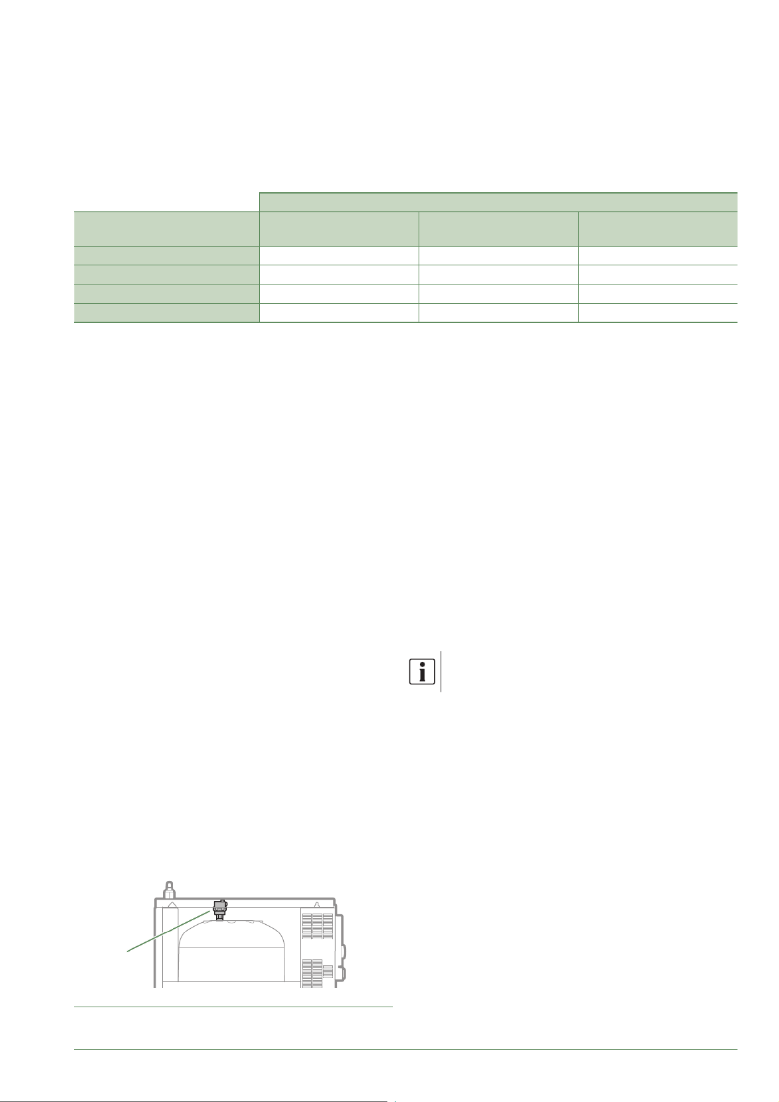
fi g. 38 - Hydraulic unit automatic bleeder valve
P
►
Filling and bleeding the installation
Check the pipe fi xings, tightness of the connectors and
the stability of the hydraulic unit.
Check the direction in which the water is circulating and
that all the valves are open.
Proceed to fi ll the installation.
Do not operate the circulation pump during fi lling.
Open all the drain valves in the installation and the
bleeder valve on the hydraulic unit ( ) to expel the air P
contained in the pipes.
Close the drain valves and add water until the pressure
in the hydraulic circuit reaches 1 bar.
Check that the hydraulic circuit has been bled correctly.
Check there are no leaks.
After the " Commissioning", page 46 stage, and
once the machine has started, bleed the hydraulic unit
again (2 litres of water).
Precise fi lling pressure is determined by the
water pressure in the installation.
Waterstage Split Comfort DHW Serie / INSTALLATION / 2130 - EN
- 34 -
Electrical connections
Before performing any maintenance, make sure that all power supplies have been
cut off .
Electrical installation must be performed in accordance with current regulations.
The electrical diagram for the hydraulic unit is shown on fi g. 58, page 78.
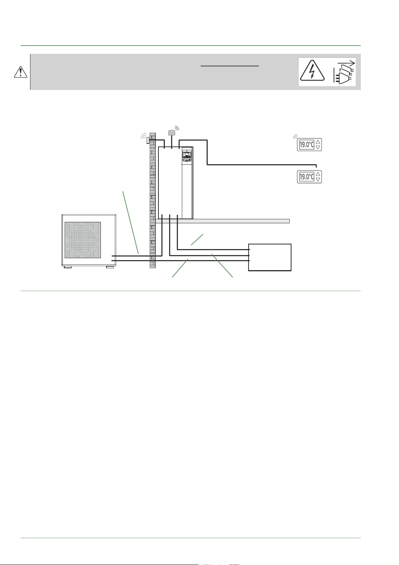
fi g. 39 - Overall layout of electrical connections for a simple installation (1 heating circuit)
Outside sensor
Cable 2 x 0.75 mm²
Interconnection between
outdoor unit and hydraulic unit
Phase, Neutral, Earth, Communication bus)
Cable 4 G 1.5 mm²
Wireless room thermostat (option)
Room thermostat (option)
Cable 2 x 0.5 mm²
Electrical backup power supply
(see table below)
DHW power supply
(phase, neutral, earth) Cable 3 G 1.5 mm²
General electrical supply
(phase, neutral, earth) (see table below)
Electrical
Board
or
Waterstage Split Comfort DHW Serie / INSTALLATION / 2130 - EN
- 36 -
►
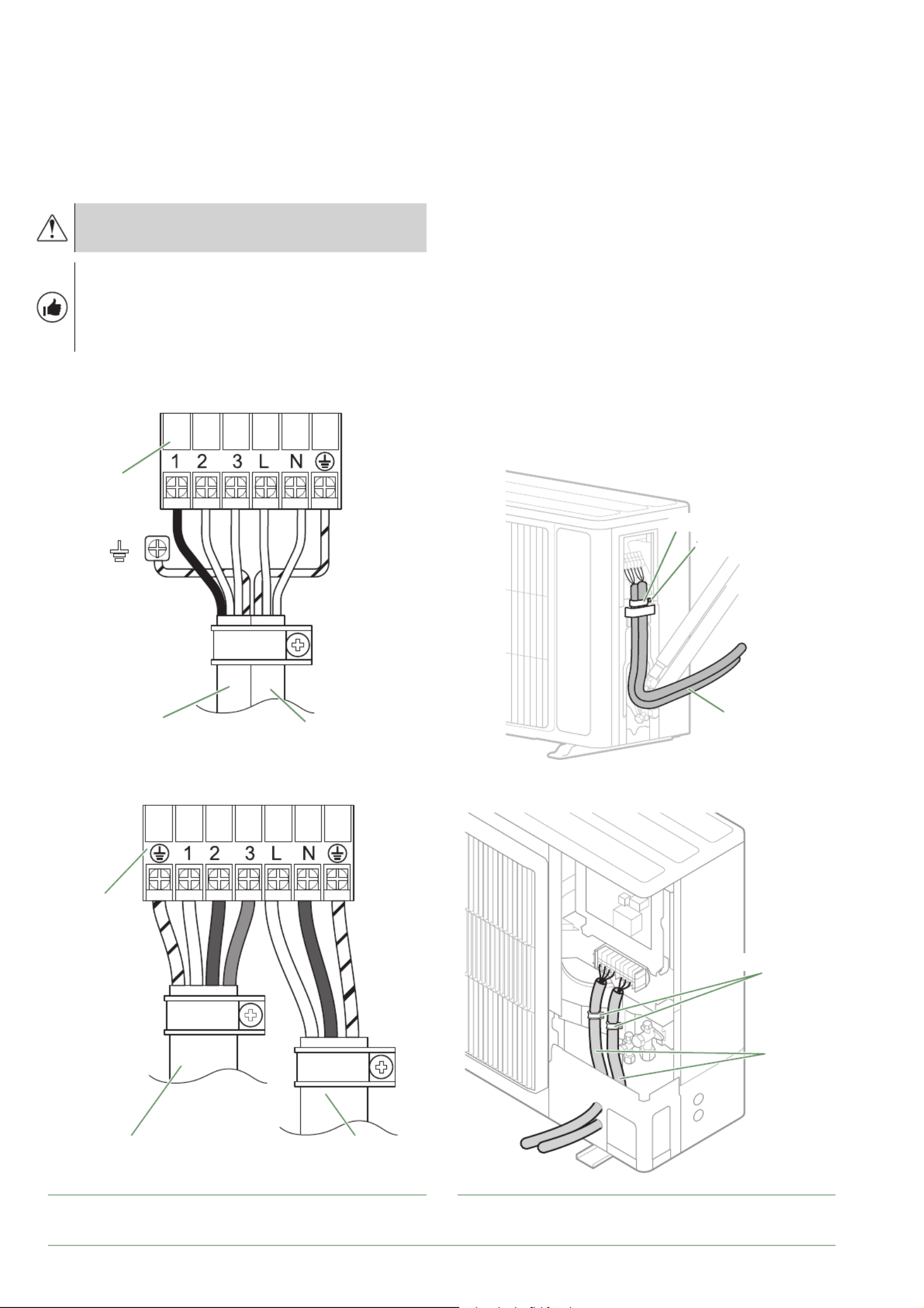
Outdoor unit
Access to connection terminals:
• Model 5, 6 & 8
- Remove the cowl.
• Model 10
- Remove the front panel.
Avoid contact between cables and refrigeration
valves / connections.
Use cable clamps to prevent any power cables
from being disconnected accidentally.
Fill in the space where the cables enter the
outdoor unit with the insulating plate.
fi g. 40 - Connections to outdoor unit's terminal block fi g. 41 - Access to outdoor unit's terminal block
Câbles
Cable clamp
Cable
Screws
Bornier
General power cable
Interconnection
between outdoor unit
and hydraulic unit
■Models 5, 6 and 8
■Models 5, 6 and 8
Bornier
Interconnection
between outdoor unit
and hydraulic unit
General power cable
■Model 10
■Model 10
Cable
Cable clamp
Waterstage Split Comfort DHW Serie / INSTALLATION / 2130 - EN
- 38 -
►
Outside sensor
The outside sensor is required for correct operation of
the heat pump.
Please see the fi tting instructions on the sensor’s
packaging.
Place the sensor on the coldest side of the building,
generally the northern or north-western side.
It must not be exposed to morning sun.
It must be installed so as to be easily accessible but at
least 2.5m from the ground.
It is essential that it is not placed near any sources of
heat such as fl ues, upper parts of doors and windows,
near extractor vents, under balconies and eaves,
or anywhere which would insulate the sensor from
variations in the outdoor air temperature.
- Connect the outside sensor to connector X84 ( fi g. 45)
(terminals and ) on the heat pump control board.M B9
►
Room sensor (option)
The room sensor is optional.
Please see the fi tting instructions on the sensor’s
packaging.
The sensor must be installed in the living room area on
an unobstructed wall. It must be installed so as to be
easily accessible.
Avoid direct sources of heat (chimney, television,
cooking surfaces, sun) and draughty areas (ventilation,
door, etc.).
Draughts in buildings are often brought about by cold air
blowing through the electrical ducting. Lag the electrical
ducts if there is a cold draught behind the room sensor.
▼
Installing a room sensor
■Room thermostat (fi g. 45)
- Connect the sensor to the connector of the heat X86
pump’s regulator board using the connector provided
(terminals , ).1 2
■Room thermostat radio (fi g. 45)
- Please refer to the instructions.
▼
Fan convector zone
If the installation is equipped with fan convectors or
dynamic radiators, do not use a room sensor.
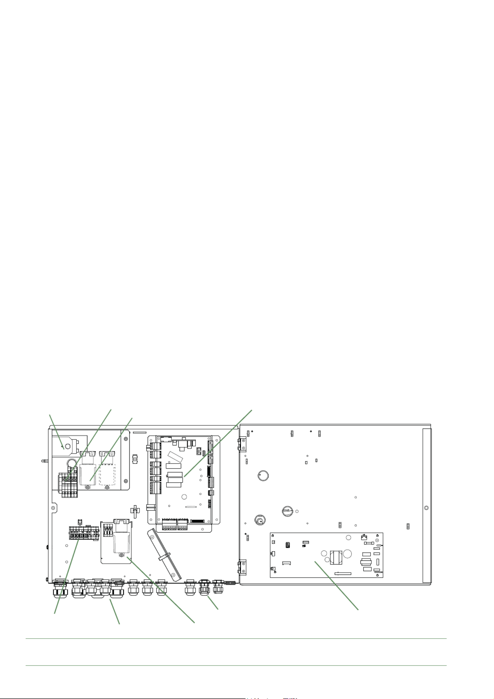
fi g. 43 - Description of the hydraulic unit's electrical control box
HP controller
Safety thermostat Power supply terminal block
Power Relay for electric backup
Cable grommets (power)
Interface Board
Cable grommets (sensors)
DHW Relay + Terminal(sensors)
Terminal
Waterstage Split Comfort DHW Serie / INSTALLATION / 2130 - EN
Termékspecifikációk
| Márka: | Fujitsu |
| Kategória: | légkondicionáló |
| Modell: | WGHA080ML3 |
Szüksége van segítségre?
Ha segítségre van szüksége Fujitsu WGHA080ML3, tegyen fel kérdést alább, és más felhasználók válaszolnak Önnek
Útmutatók légkondicionáló Fujitsu

4 Április 2025
3 Április 2025
1 Április 2025
30 Március 2025
19 Március 2025
14 Január 2025
12 Január 2025
9 Január 2025
9 Január 2025
9 Január 2025
Útmutatók légkondicionáló
- légkondicionáló Mestic
- légkondicionáló Samsung
- légkondicionáló Beko
- légkondicionáló Dometic
- légkondicionáló Electrolux
- légkondicionáló Whirlpool
- légkondicionáló Nedis
- légkondicionáló LG
- légkondicionáló Grundig
- légkondicionáló Ariston Thermo
- légkondicionáló Candy
- légkondicionáló Philips
- légkondicionáló Gorenje
- légkondicionáló Adler
- légkondicionáló Princess
- légkondicionáló Oregon Scientific
- légkondicionáló Bosch
- légkondicionáló NewAir
- légkondicionáló Theben
- légkondicionáló Panasonic
- légkondicionáló Zanussi
- légkondicionáló MPM
- légkondicionáló AEG
- légkondicionáló Emerio
- légkondicionáló Sharp
- légkondicionáló Einhell
- légkondicionáló Toshiba
- légkondicionáló Ozito
- légkondicionáló Bartscher
- légkondicionáló Hyundai
- légkondicionáló Hisense
- légkondicionáló HQ
- légkondicionáló Siemens
- légkondicionáló Medion
- légkondicionáló Exquisit
- légkondicionáló Corbero
- légkondicionáló Camry
- légkondicionáló TCL
- légkondicionáló Xiaomi
- légkondicionáló Danby
- légkondicionáló DeLonghi
- légkondicionáló Insignia
- légkondicionáló Heinner
- légkondicionáló Infiniton
- légkondicionáló Wilfa
- légkondicionáló Klarstein
- légkondicionáló VOX
- légkondicionáló Be Cool
- légkondicionáló Tripp Lite
- légkondicionáló Vivax
- légkondicionáló Thomson
- légkondicionáló Fuave
- légkondicionáló Unold
- légkondicionáló Ardes
- légkondicionáló Orima
- légkondicionáló Eden
- légkondicionáló Jocel
- légkondicionáló Bimar
- légkondicionáló Starlyf
- légkondicionáló Clatronic
- légkondicionáló Bomann
- légkondicionáló Bauknecht
- légkondicionáló Amana
- légkondicionáló Hotpoint
- légkondicionáló Haier
- légkondicionáló Frigidaire
- légkondicionáló Mitsubishi
- légkondicionáló Cecotec
- légkondicionáló Sencor
- légkondicionáló Qlima
- légkondicionáló Baxi
- légkondicionáló Innoliving
- légkondicionáló Avidsen
- légkondicionáló Rowenta
- légkondicionáló Westinghouse
- légkondicionáló Hitachi
- légkondicionáló Inventum
- légkondicionáló BLUEPALM
- légkondicionáló Telefunken
- légkondicionáló GoldAir
- légkondicionáló Domo
- légkondicionáló Russell Hobbs
- légkondicionáló Carson
- légkondicionáló SHE
- légkondicionáló Create
- légkondicionáló Black & Decker
- légkondicionáló G3 Ferrari
- légkondicionáló Wood's
- légkondicionáló Vaillant
- légkondicionáló Livington
- légkondicionáló Orbegozo
- légkondicionáló Daewoo
- légkondicionáló Livoo
- légkondicionáló ARGO
- légkondicionáló Balay
- légkondicionáló Hotpoint Ariston
- légkondicionáló OK
- légkondicionáló GE
- légkondicionáló Guzzanti
- légkondicionáló Concept
- légkondicionáló Whynter
- légkondicionáló SVAN
- légkondicionáló Keystone
- légkondicionáló Sanus
- légkondicionáló Alaska
- légkondicionáló Consul
- légkondicionáló TriStar
- légkondicionáló Zelmer
- légkondicionáló Suntec
- légkondicionáló Bavaria
- légkondicionáló APC
- légkondicionáló CyberPower
- légkondicionáló Daizuki
- légkondicionáló Koenic
- légkondicionáló Daikin
- légkondicionáló Midea
- légkondicionáló Trisa
- légkondicionáló Electroline
- légkondicionáló Heller
- légkondicionáló Progress
- légkondicionáló Kogan
- légkondicionáló Profilo
- légkondicionáló Honeywell
- légkondicionáló Truma
- légkondicionáló Broan
- légkondicionáló Stirling
- légkondicionáló Mesko
- légkondicionáló Sigma
- légkondicionáló Furrion
- légkondicionáló Remeha
- légkondicionáló Dimplex
- légkondicionáló Master
- légkondicionáló Aspes
- légkondicionáló Kenmore
- légkondicionáló Thermex
- légkondicionáló DCG
- légkondicionáló Lanaform
- légkondicionáló Melissa
- légkondicionáló Trotec
- légkondicionáló Manta
- légkondicionáló Blaupunkt
- légkondicionáló EcoFlow
- légkondicionáló HTW
- légkondicionáló Easy Home
- légkondicionáló Korona
- légkondicionáló Conrad
- légkondicionáló Taurus
- légkondicionáló Comfee
- légkondicionáló Be Quiet!
- légkondicionáló Logik
- légkondicionáló Finlux
- légkondicionáló Gree
- légkondicionáló AKAI
- légkondicionáló H.Koenig
- légkondicionáló TechniSat
- légkondicionáló GlobalTronics
- légkondicionáló Emerson
- légkondicionáló Sôlt
- légkondicionáló Kalorik
- légkondicionáló Sanyo
- légkondicionáló Frilec
- légkondicionáló Philco
- légkondicionáló ECG
- légkondicionáló Rotel
- légkondicionáló Esatto
- légkondicionáló Element
- légkondicionáló Ufesa
- légkondicionáló Meireles
- légkondicionáló Galanz
- légkondicionáló Friedrich
- légkondicionáló Rinnai
- légkondicionáló Argoclima
- légkondicionáló Ausclimate
- légkondicionáló Brandt
- légkondicionáló RCA
- légkondicionáló Bestron
- légkondicionáló Soler & Palau
- légkondicionáló SereneLife
- légkondicionáló Ravanson
- légkondicionáló Teesa
- légkondicionáló Carrier
- légkondicionáló Lavorwash
- légkondicionáló Becken
- légkondicionáló OneConcept
- légkondicionáló BOSFOR
- légkondicionáló Tatung
- légkondicionáló Olimpia Splendid
- légkondicionáló ActronAir
- légkondicionáló Mistral
- légkondicionáló Coolix
- légkondicionáló Orava
- légkondicionáló Arçelik
- légkondicionáló Eurom
- légkondicionáló Climadiff
- légkondicionáló Celiera
- légkondicionáló Sauber
- légkondicionáló IFB
- légkondicionáló Salicru
- légkondicionáló Sonnenkönig
- légkondicionáló Tectro
- légkondicionáló Matsui
- légkondicionáló Toyotomi
- légkondicionáló TOSOT
- légkondicionáló Zibro
- légkondicionáló Airlux
- légkondicionáló Aermec
- légkondicionáló Acson
- légkondicionáló Airwell
- légkondicionáló Amcor
- légkondicionáló Andrews
- légkondicionáló Akira
- légkondicionáló Aircooler
- légkondicionáló Ariston
- légkondicionáló Airview
- légkondicionáló Calor
- légkondicionáló Tomado
- légkondicionáló Vestel
- légkondicionáló Itho
- légkondicionáló Mabe
- légkondicionáló Anslut
- légkondicionáló Termozeta
- légkondicionáló Eldom
- légkondicionáló Jocca
- légkondicionáló Nabo
- légkondicionáló Defy
- légkondicionáló Buderus
- légkondicionáló Premium
- légkondicionáló White Knight
- légkondicionáló Profile
- légkondicionáló Ferroli
- légkondicionáló Inventor
- légkondicionáló Evolar
- légkondicionáló Kubo
- légkondicionáló Elba
- légkondicionáló Proline
- légkondicionáló Royal Sovereign
- légkondicionáló Meaco
- légkondicionáló Ansonic
- légkondicionáló Kelvinator
- légkondicionáló Malmbergs
- légkondicionáló Everglades
- légkondicionáló Heylo
- légkondicionáló ElectriQ
- légkondicionáló Listo
- légkondicionáló Daitsu
- légkondicionáló Milectric
- légkondicionáló Saunier Duval
- légkondicionáló Challenge
- légkondicionáló Duux
- légkondicionáló Alpatec
- légkondicionáló Primo
- légkondicionáló Godrej
- légkondicionáló Maiko
- légkondicionáló Aircool
- légkondicionáló Waeco
- légkondicionáló Essentiel B
- légkondicionáló Team
- légkondicionáló Equation
- légkondicionáló Edy
- légkondicionáló Prime3
- légkondicionáló Blumfeldt
- légkondicionáló Edgestar
- légkondicionáló Maxicool
- légkondicionáló KDK
- légkondicionáló Dantherm
- légkondicionáló Carrefour Home
- légkondicionáló Equator
- légkondicionáló Kunft
- légkondicionáló Day
- légkondicionáló Koenig
- légkondicionáló Fakir
- légkondicionáló MundoClima
- légkondicionáló Proklima
- légkondicionáló Home Electric
- légkondicionáló Eco-De
- légkondicionáló REMKO
- légkondicionáló Fairland
- légkondicionáló DEXP
- légkondicionáló Just Fire
- légkondicionáló Teco
- légkondicionáló Iceberg
- légkondicionáló Chigo
- légkondicionáló RIDGID
- légkondicionáló Hokkaido
- légkondicionáló Tarrington House
- légkondicionáló Gutfels
- légkondicionáló Telair
- légkondicionáló Klarbach
- légkondicionáló MDV
- légkondicionáló Mobile Airco
- légkondicionáló Heiko
- légkondicionáló Firstline
- légkondicionáló Qlima - Zibro
- légkondicionáló Holland Electro
- légkondicionáló Handson
- légkondicionáló Bryant
- légkondicionáló Klima1stKlaas
- légkondicionáló Emmeti
- légkondicionáló Evapolar
- légkondicionáló Elgin
- légkondicionáló Tronix
- légkondicionáló Liebert
- légkondicionáló Sencys
- légkondicionáló Frigor
- légkondicionáló Fronius
- légkondicionáló TechnoLife
- légkondicionáló Shinco
- légkondicionáló Innova
- légkondicionáló Avalon Bay
- légkondicionáló SMC
- légkondicionáló D-Let
- légkondicionáló Domair
- légkondicionáló Braemar
- légkondicionáló Klimaire
- légkondicionáló General
- légkondicionáló Duracraft
- légkondicionáló SEEGER
- légkondicionáló Thermo Comfort
- légkondicionáló Khind
- légkondicionáló LERAN
- légkondicionáló General Electric
- légkondicionáló SPT
- légkondicionáló Mizushi
- légkondicionáló Simplicity
- légkondicionáló Sinclair
- légkondicionáló Aerian
- légkondicionáló Moa
- légkondicionáló Fuji Electric
- légkondicionáló Polocool
- légkondicionáló Convair
- légkondicionáló Kibernetik
- légkondicionáló Fral
- légkondicionáló Companion
- légkondicionáló Prem-i-air
- légkondicionáló Arcoaire
- légkondicionáló Bodin
- légkondicionáló Magnavox
- légkondicionáló Zymbo
- légkondicionáló AFINTEK
- légkondicionáló Brivis
- légkondicionáló MRCOOL
- légkondicionáló Volteno
- légkondicionáló B-Air
- légkondicionáló Monzana
- légkondicionáló Trilec
- légkondicionáló Kaden
- légkondicionáló Geist
- légkondicionáló Avallon
- légkondicionáló Columbia Vac
- légkondicionáló TURBRO
- légkondicionáló House & Luft
- légkondicionáló Bonaire
- légkondicionáló Evapcool
- légkondicionáló Protector
- légkondicionáló Vostok
- légkondicionáló American Comfort
- légkondicionáló Ocean Breeze
- légkondicionáló Quirky
- légkondicionáló Krone
- légkondicionáló KwiKool
- légkondicionáló SMD
- légkondicionáló Big Ass Fans
- légkondicionáló Arctic King
- légkondicionáló Artrom
- légkondicionáló Senville
- légkondicionáló Climachill
- légkondicionáló Commercial Cool
- légkondicionáló Riffel
- légkondicionáló Heat Controller
- légkondicionáló Luma Comfort
- légkondicionáló Norpole
- légkondicionáló Kaco
- légkondicionáló Omega Altise
- légkondicionáló Middle Atlantic
- légkondicionáló Goodwe
- légkondicionáló Swegon
- légkondicionáló InAlto
- légkondicionáló JHS
- légkondicionáló FREONIC
- légkondicionáló ARCTIC WIND
- légkondicionáló KuulAire
- légkondicionáló Cool-Space
- légkondicionáló Aconatic
- légkondicionáló AireMax
- légkondicionáló VänEE
- légkondicionáló Mayer
- légkondicionáló Perfect Aire
- légkondicionáló Koldfront
- légkondicionáló Yamazen
- légkondicionáló Universal Blue
- légkondicionáló Symphony
- légkondicionáló Corona
- légkondicionáló Hoffman
Legújabb útmutatók légkondicionáló

10 Április 2025

10 Április 2025
10 Április 2025

9 Április 2025
9 Április 2025

9 Április 2025
9 Április 2025

9 Április 2025
9 Április 2025
9 Április 2025