Használati útmutató Dürkopp Adler 34
Olvassa el alább 📖 a magyar nyelvű használati útmutatót Dürkopp Adler 34 (188 oldal) a varrógép kategóriában. Ezt az útmutatót 4 ember találta hasznosnak és 2 felhasználó értékelte átlagosan 4.5 csillagra
Oldal 1/188

550-12-33/34
Operating Instructions

All rights reserved.
Property of Dürkopp Adler GmbH and protected by copyright. Any reuse
of these contents, including extracts, is prohibited without the prior
written approval of Dürkopp Adler GmbH.
Copyright © Dürkopp Adler GmbH 2022
IMPORTANT
READ CAREFULLY BEFORE USE
KEEP FOR FUTURE REFERENCE

Table of Contents
Operating Instructions 550-12-33/34 - 00.0 - 05/2022 1
1 About these instructions ....................................................................5
1.1 For whom are these instructions intended? .......................................... 5
1.2 Representation conventions – symbols and characters ........................ 6
1.3 Other documents...................................................................................7
1.4 Liability ..................................................................................................8
2 Safety....................................................................................................9
2.1 Basic safety instructions........................................................................9
2.2 Signal words and symbols used in warnings....................................... 11
3 Machine description.......................................................................... 15
3.1 Components of the machine ............................................................... 15
3.2 Proper use........................................................................................... 16
3.3 Declaration of Conformity.................................................................... 17
4 Operation ........................................................................................... 19
4.1 Preparing the machine for operation ................................................... 19
4.2 Switching on and off the machine ....................................................... 20
4.3 Inserting/changing the needle ............................................................. 22
4.4 Threading the needle thread ...............................................................24
4.5 Threading the hook thread ..................................................................27
4.6 Threading the reinforcement tape ....................................................... 31
4.6.1 Threading the reinforcement tape from the top................................... 31
4.6.2 Threading the reinforcement tape from the bottom .............................34
4.7 Thread tension .................................................................................... 37
4.7.1 Setting the needle thread quantity....................................................... 38
4.7.2 Setting the hook thread quantity.......................................................... 40
4.7.3 Setting thread pre-tensioner/tape tensioner ........................................ 43
4.8 Switching the tape tensioner for the reinforcement tape on/off ........... 45
4.9 Setting the tape brake ......................................................................... 46
4.10 Locking the sewing feet at top dead center.........................................48
4.11 Setting the sewing foot stroke .............................................................49
4.12 Setting the sewing foot pressure .........................................................50
4.13 Using the knee button during sewing .................................................. 51
4.14 Switching maximum stroke on and off.................................................53
4.15 Switching the edge cutter on and off ................................................... 53
4.16 Switching on and off the sewing lamp ................................................. 54
4.17 Setting the stitch length ....................................................................... 55
4.18 Sewing................................................................................................. 56
5 Programming Commander Pro ........................................................ 59
5.1 Commander Pro control panel ............................................................ 59
5.2 Navigating the Commander Pro control panel ....................................59
5.2.1 Symbols and tiles ................................................................................60

Table of Contents
2 Operating Instructions 550-12-33/34 - 00.0 - 05/2022
5.2.2 Entering values....................................................................................62
5.2.3 Navigating the burger menu ................................................................ 62
5.2.4 Navigation during the start of the control panel................................... 63
5.3 User Management............................................................................... 63
5.3.1 User login ............................................................................................ 65
5.3.2 Authorizations as Default Technician ........................................68
5.4 Software operating modes .................................................................. 76
5.5 Using Manual mode ............................................................................ 77
5.5.1 Setting up the user interface ...............................................................77
5.5.2 Setting the parameters........................................................................81
5.5.3 Setting the cross-seam parameters ................................................ 82
5.5.4 Setting the Seam Begin parameters .................................................88
5.5.5 Setting the Segment parameters........................................................89
5.5.6 Setting the Seam End parameters...................................................... 90
5.6 Using Automatic mode ........................................................................90
5.6.1 Sewing in Automatic mode.................................................................. 93
5.6.2 Canceling a program in Automatic mode ............................................ 94
5.7 Using Programming mode................................................................... 94
5.7.1 Managing programs ............................................................................96
5.7.2 Managing seams................................................................................. 96
5.7.3 Editing the segments of a seam..........................................................97
5.7.4 Managing segments ............................................................................98
5.7.5 Setting program parameters................................................................99
5.7.6 Setting the Seam Begin/Segment Begin parameters .................104
5.7.7 Setting the Segment parameters ...................................................... 105
5.7.8 Setting the Segment End/Seam End parameters..........................107
5.8 Importing/exporting programs ........................................................... 108
5.9 Performing a software update ...........................................................109
6 Maintenance.....................................................................................111
6.1 Maintenance intervals .......................................................................112
6.2 Cleaning ............................................................................................ 113
6.3 Lubricating......................................................................................... 114
6.3.1 Checking the lubrication of the machine head .................................. 116
6.3.2 Checking the hook lubrication ........................................................... 117
6.4 Servicing the pneumatic system........................................................ 120
6.4.1 Setting the operating pressure .......................................................... 120
6.4.2 Draining the water condensation.......................................................121
6.4.3 Cleaning the filter element.................................................................122
6.5 Parts list.............................................................................................123
7 Setup ................................................................................................125
7.1 Checking the scope of delivery ......................................................... 125
7.2 Removing the transport locks............................................................ 125
7.3 Assembling the reel stand ................................................................. 126

Table of Contents
Operating Instructions 550-12-33/34 - 00.0 - 05/2022 3
7.4 Setting the working height ................................................................. 128
7.5 Setting the pedal ...............................................................................130
7.6 Inserting the machine head ............................................................... 132
7.7 Tilting and erecting the machine head .............................................. 134
7.8 Electrical connection ......................................................................... 136
7.9 Establishing equipotential bonding....................................................136
7.10 Pneumatic connection ....................................................................... 137
7.10.1 Assembling the compressed air maintenance unit............................ 137
7.10.2 Setting the operating pressure ..........................................................138
7.11 Lubricating.........................................................................................139
7.12 Performing a test run......................................................................... 141
8 Decommissioning ...........................................................................143
9 Disposal ........................................................................................... 145
10 Troubleshooting ..............................................................................147
10.1 Customer Service..............................................................................147
10.2 Messages of the software .................................................................147
10.3 Errors in sewing process ................................................................... 171
11 Technical data .................................................................................173
11.1 Data and characteristic values .......................................................... 173
11.2 Requirements for trouble-free operation ...........................................174
12 Appendix .......................................................................................... 175
12.1 Wiring diagram .................................................................................. 175
12.2 Tabletop drawing...............................................................................181

Table of Contents
4 Operating Instructions 550-12-33/34 - 00.0 - 05/2022

About these instructions
Operating Instructions 550-12-33/34 - 00.0 - 05/2022 5
1 About these instructions
These instructions have been prepared with utmost care.
They contain information and notes intended to ensure long-term
and reliable operation.
Should you notice any discrepancies or if you have improvement
requests, then we would be glad to receive your feedback through
Customer Service (p. 147).
Consider the instructions part of the product and store them in a
place where they are readily available.
1.1 For whom are these instructions intended?
These instructions are intended for:
• Operators:
This group is familiar with the machine and has access to
the instructions. Specifically, chapter Operation (p. 19)
is important for the operators.
• Specialists:
This group has the appropriate technical training for
performing maintenance or repairing malfunctions.
Specifically, the chapter Setup (p. 125) is important for
specialists.
Service Instructions are supplied separately.
With regard to minimum qualification and other requirements to be
met by personnel, please also follow the chapter Safety (p. 9).

About these instructions
Operating Instructions 550-12-33/34 - 00.0 - 05/2022 7
Information
Additional information, e.g. on alternative operating options.
Order
Specifies the work to be performed before or after a setting.
References
Reference to another section in these instructions.
Safety Important warnings for the user of the machine are specifically
marked. Since safety is of particular importance, hazard symbols,
levels of danger and their signal words are described separately
in the chapter Safety (p. 9).
Location
information
If no other clear location information is used in a figure, indications
of right or left are always from the user's point of view.
1.3 Other documents
The machine includes components from other manufacturers.
Each manufacturer has performed a hazard assessment for these
purchased parts and confirmed their design compliance with
applicable European and national regulations. The proper use of
the built-in components is described in the corresponding manu-
facturer's instructions.

About these instructions
8 Operating Instructions 550-12-33/34 - 00.0 - 05/2022
1.4 Liability
All information and notes in these instructions have been compiled
in accordance with the latest technology and the applicable
standards and regulations.
Dürkopp Adler cannot be held liable for any damage resulting
from:
• Breakage and damage during transport
• Failure to observe these instructions
• Improper use
• Unauthorized modifications to the machine
• Use of untrained personnel
• Use of unapproved parts
Transport
Dürkopp Adler cannot be held liable for breakage and transport
damages. Inspect the delivery immediately upon receiving it.
Report any damage to the last transport manager. This also
applies if the packaging is not damaged.
Leave machines, equipment and packaging material in the con-
dition in which they were found when the damage was discovered.
This will ensure any claims against the transport company.
Report all other complaints to Dürkopp Adler immediately after
receiving the product.

Safety
Operating Instructions 550-12-33/34 - 00.0 - 05/2022 9
2 Safety
This chapter contains basic information for your safety. Read the
instructions carefully before setting up or operating the machine.
Make sure to follow the information included in the safety instruc-
tions. Failure to do so can result in serious injury and property
damage.
2.1 Basic safety instructions
The machine may only be used as described in these instructions.
The instructions should be available at the machine's location at
all times.
Work on live components and equipment is prohibited. Exceptions
are defined in the DIN VDE 0105.
For the following work, switch off the machine at the main switch
or disconnect the power plug:
• Replacing the needle or other sewing tools
• Leaving the workstation
• Performing maintenance work and repairs
• Threading
Missing or faulty parts could impair safety and damage the
machine. Only use original parts from the manufacturer.
Transport Use a lifting carriage or forklift to transport the machine. Raise the
machine max. 20 mm and secure it to prevent it from slipping off.
Setup The connecting cable must have a power plug approved in the
relevant country. The power plug may only be assembled to the
power cable by qualified specialists.
Obligations
of the operator
Follow the country-specific safety and accident prevention regu-
lations and the legal regulations concerning industrial safety and
the protection of the environment.

Safety
10 Operating Instructions 550-12-33/34 - 00.0 - 05/2022
All the warnings and safety signs on the machine must always be
in legible condition. Do not remove!
Missing or damaged warnings and safety signs must be replaced
immediately.
Requirements
to be met by
the personnel
Only qualified specialists may:
• Setting up the machine
• Performing maintenance work and repairs
• Performing work on electrical equipment
Only authorized persons may work on the machine and must first
have understood these instructions.
Operation Check the machine during operating for any externally visible
damage. Stop working if you notice any changes to the machine.
Report any changes to your supervisor. Do not use a damaged
machine any further.
Safety
equipment
Safety equipment should not be removed or deactivated. If it is
essential to remove or deactivate safety equipment for a repair
operation, it must be assembled and put back into operation
immediately afterward.
Safety
Operating Instructions 550-12-33/34 - 00.0 - 05/2022 11
2.2 Signal words and symbols used in warnings
Warnings in the text are distinguished by color bars. The color
scheme is based on the severity of the danger. Signal words
indicate the severity of the danger.
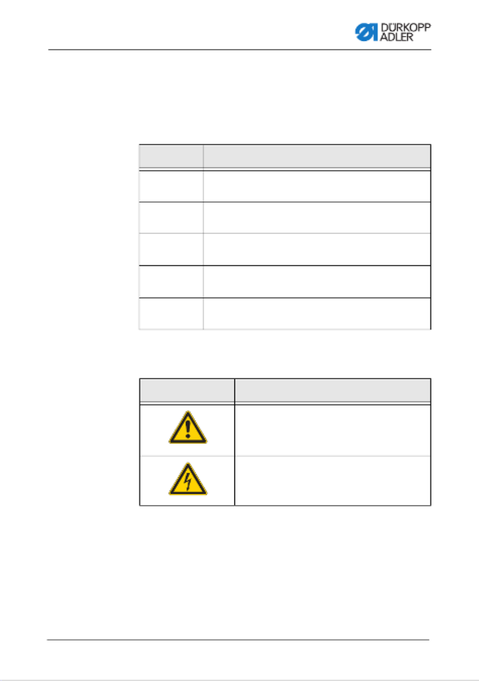
Signal words Signal words and the hazard they describe:
Symbols The following symbols indicate the type of danger to personnel:
Signal word Meaning
DANGER (with hazard symbol)
If ignored, fatal or serious injury will result
WARNING (with hazard symbol)
If ignored, fatal or serious injury can result
CAUTION (with hazard symbol)
If ignored, moderate or minor injury can result
CAUTION (with hazard symbol)
If ignored, environmental damage can result
NOTICE (without hazard symbol)
If ignored, property damage can result
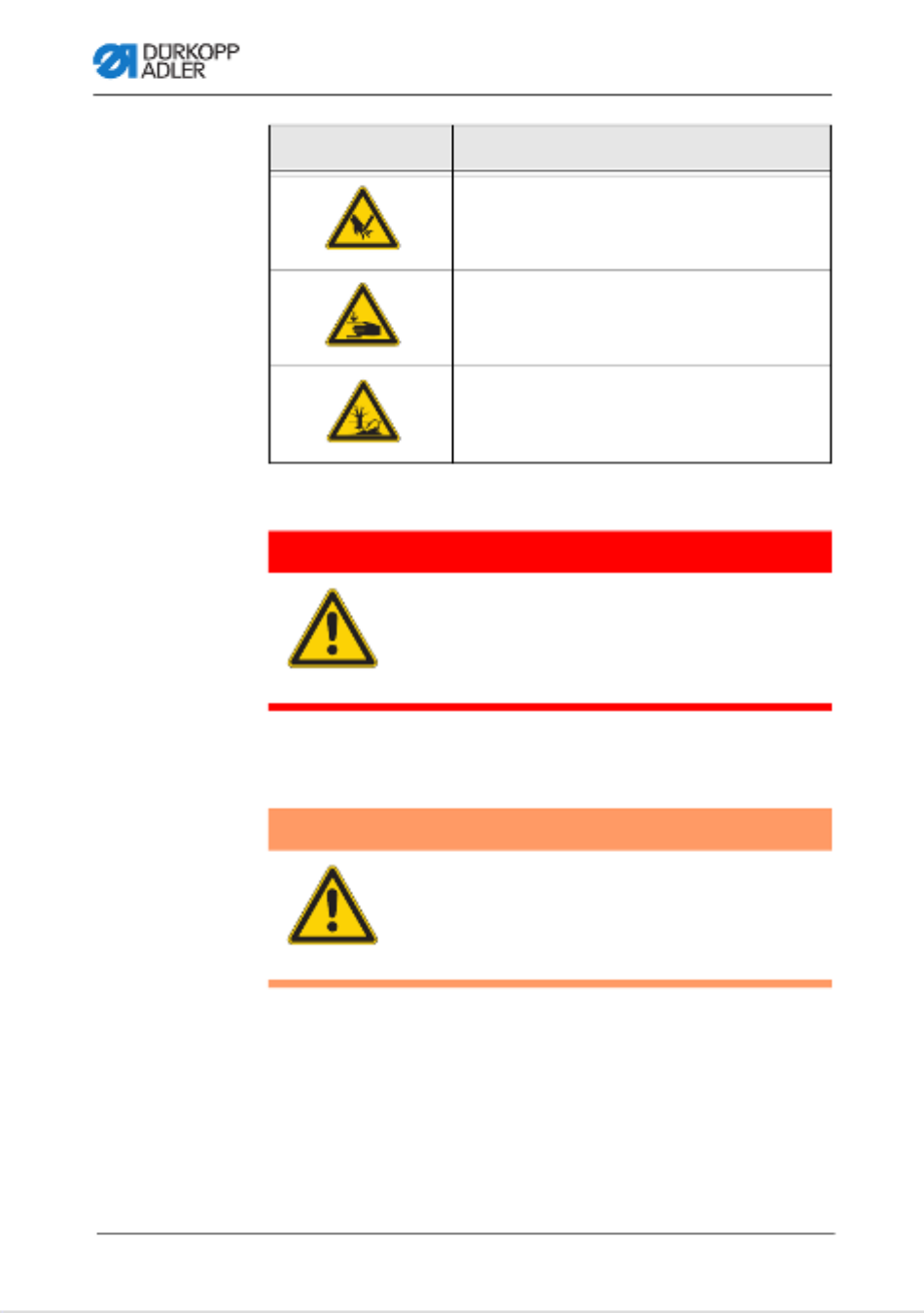
Symbol Type of danger
General
Electric shock
Safety
12 Operating Instructions 550-12-33/34 - 00.0 - 05/2022
Examples Examples of the layout of warnings in the text:
This is what a warning looks like for a hazard that will result
in serious injury or even death if ignored.
This is what a warning looks like for a hazard that could
result in serious or even fatal injury if ignored.
Puncture
Crushing
Environmental damage
Symbol Type of danger
DANGER
Type and source of danger!
Consequences of non-compliance.
Measures for avoiding the danger.
WARNING
Type and source of danger!
Consequences of non-compliance.
Measures for avoiding the danger.

Safety
Operating Instructions 550-12-33/34 - 00.0 - 05/2022 13
This is what a warning looks like for a hazard that could
result in moderate or minor injury if the warning is ignored.
This is what a warning looks like for a hazard that could
result in property damage if ignored.
This is what a warning looks like for a hazard that could
result in environmental damage if ignored.
CAUTION
Type and source of danger!
Consequences of non-compliance.
Measures for avoiding the danger.
NOTICE
Type and source of danger!
Consequences of non-compliance.
Measures for avoiding the danger.
CAUTION
Type and source of danger!
Consequences of non-compliance.
Measures for avoiding the danger.

Safety
14 Operating Instructions 550-12-33/34 - 00.0 - 05/2022
Machine description
Operating Instructions 550-12-33/34 - 00.0 - 05/2022 15
3 Machine description
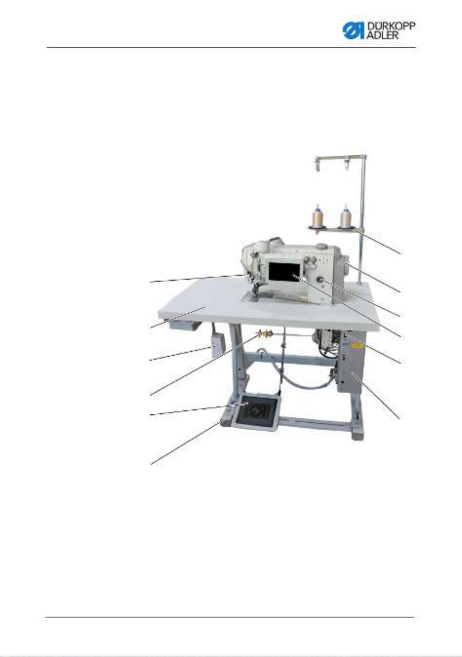
3.1 Components of the machine
Fig. 1: Components of the machine
(1) - External sewing lamp
(2) - Tabletop
(3) - Knee button
(4) - Lower tape feeder
(5) - Pedal
(6) - Stand
(7) - Control
(8) - Main switch
(9) - Control panel Commander Pro
(10)- Oil-wick lubrication
(11) - Handwheel
(12) - Reel stand
①
②
③
④
⑤
⑥
⑦
⑧
⑨
⑩
⑪
⑫

Machine description
16 Operating Instructions 550-12-33/34 - 00.0 - 05/2022
3.2 Proper use
The machine may only be used with sewing material that satisfies
the requirements of the specific application at hand.
The machine is intended only for use with dry sewing material.
The sewing material must not contain any hard objects.
The needle thicknesses permissible for the machine are listed in
the Technical data (p. 173) chapter.
The seam must be completed with a thread that satisfies the
requirements of the specific application at hand.
The machine is intended for industrial use.
The machine may only be set up and operated in dry conditions on
well-maintained premises. If the machine is operated on premises
that are not dry and well-maintained, then further measures may
be required which must be compatible with DIN EN 60204-31.
Only authorized persons may work on the machine.
Dürkopp Adler cannot be held liable for damages resulting from
improper use.
WARNING
Risk of injury from live, moving and cutting
parts as well as from sharp parts!
Improper use can result in electric shock,
crushing, cutting and punctures.
Follow all instructions provided.
NOTICE
Non-observance will lead to property damage!
Improper use can result in material damage at the machine.
Follow all instructions provided.

Machine description
Operating Instructions 550-12-33/34 - 00.0 - 05/2022 17
3.3 Declaration of Conformity
The machine complies with European regulations ensuring health,
safety, and environmental protection as specified in the declara-
tion of conformity or in the declaration of incorporation.

Machine description
18 Operating Instructions 550-12-33/34 - 00.0 - 05/2022

Operation
Operating Instructions 550-12-33/34 - 00.0 - 05/2022 19
4 Operation
The operating sequence consists of several different steps.
Fault-free operation is necessary in order to achieve a good
sewing result.
4.1 Preparing the machine for operation
Complete the following steps in preparation of sewing before
starting to work:
• Inserting/changing the needle (p. 22)
• Threading the needle thread (p. 24)
• Threading the hook thread (p. 27).
• Setting the thread tension (p. 37)
• Threading the reinforcement tape (p. 31)
WARNING
Risk of injury from moving, cutting and sharp
parts!
Crushing, cutting and punctures are possible.
If possible, make preparations only when the
machine is switched off.

Operation
Operating Instructions 550-12-33/34 - 00.0 - 05/2022 21
Switching on the machine
To switch on the machine:
1. Ensure that the needle is up and not plunged in the material
at the bottom.
Important
The needle must be at the top dead center, ensuring that
needle and hook tip cannot become damaged during
referencing.
2. Set the main switch (3) to position I.
POWER LED (2) illuminates, and the MESSAGE LED (1)
flashes briefly.
The splash screen appears on the display:
• On the left, the class
• On the right, the firmware
The machine performs a reference run and is ready for
sewing when the display shows the start screen.
The control remains in automatic mode only for a few
seconds before switching to manual mode.
Switching off the machine
To switch off the machine:
1. Ensure that the needle is up and not plunged in the material
at the bottom.
Important
The needle must be at the top dead center, ensuring that
needle and hook tip cannot become damaged the next time
the machine is switched on and completes a reference run.
2. Set the main switch (3) to position 0.
The control panel shuts down. When the POWER LED (2)
goes out, the machine and the control are disconnected
from the power supply.
Operation
Operating Instructions 550-12-33/34 - 00.0 - 05/202222
4.3 Inserting/changing the needle
Fig. 3: Inserting/changing the needle
WARNING
Risk of injury from moving, cutting and sharp
parts!
Crushing, cutting and punctures are possible.
Only insert or change the needle with the
machine switched off.
NOTICE
Property damage may occur!
Risk of missing stitches or damage to the thread when using
thinner needles. Risk of damage to the hook tip or the needle
when using thicker needles.
Correct the settings when using needles with a different
thickness.
(1) - Needle bar
(2) - Thread guide
(3) - Threaded pin
(4) - Needle
(5) - Groove
①
②
③
④
⑤

Operation
Operating Instructions 550-12-33/34 - 00.0 - 05/2022 23
To change the needle:
1. Turn handwheel until the needle (4) is at the top dead center.
2. Loosen the threaded pin (3) through the hole in the thread
guide (2).
This requires that the thread guide (2) be assembled
completely straight to the needle bar (1).
3. Pull the needle (4) down and out.
4. Insert the new needle (4) into the hole in the needle bar (1)
until it reaches the end stop.
Important
Align the needle (4) in such a way that the groove (5) is pointing
to the rear.
5. Tighten the threaded pin (3) through the hole in the thread
guide (2).
Order
Always adjust the clearance between the hook and the needle (4)
after changing to a different needle thickness (Service
Instructions).
Disturbance
An incorrect hook distance can cause the following disturbances:
• Changing to a thinner needle:
• Missing stitches
• Thread damage
• Changing to a thicker needle:
• Damage to the hook tip
• Damage to the needle
Operation
Operating Instructions 550-12-33/34 - 00.0 - 05/202224
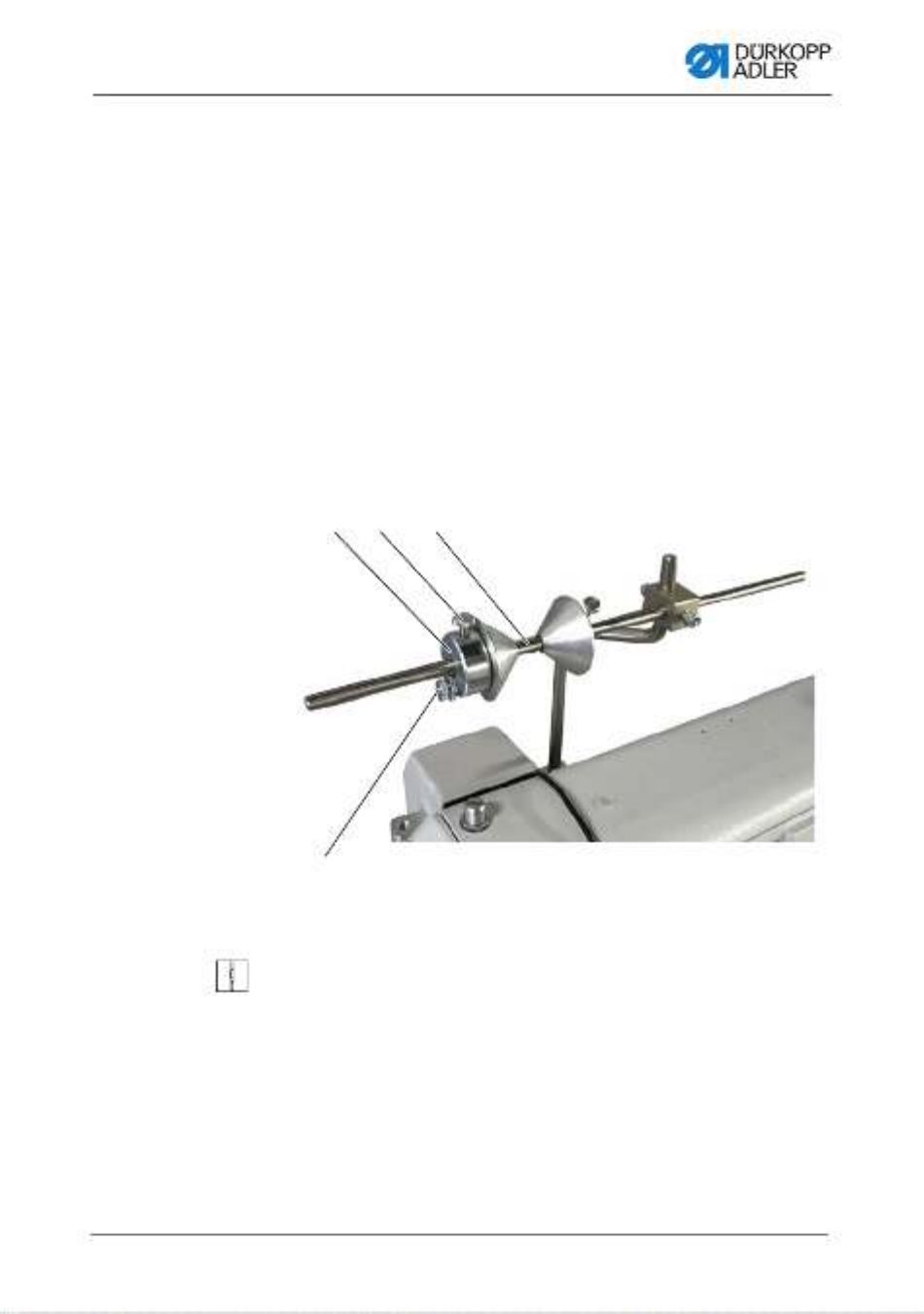
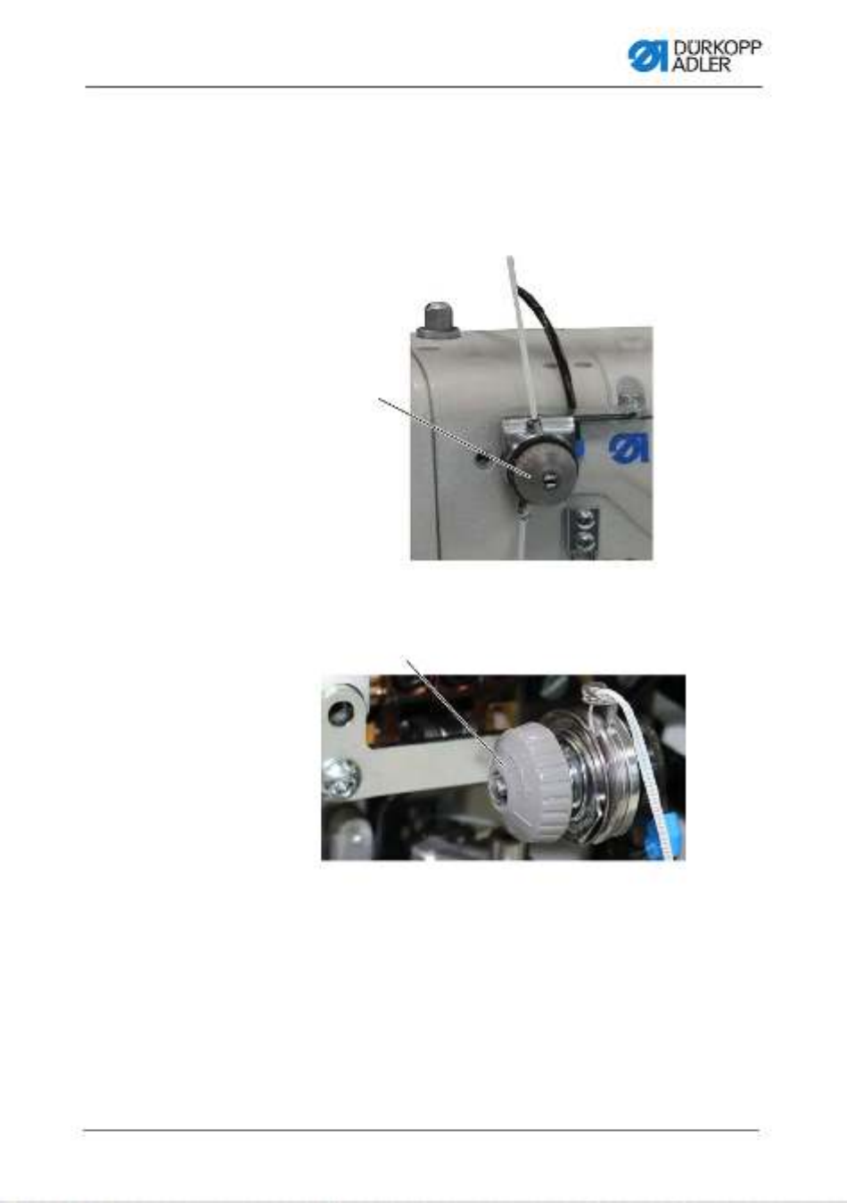
4.4 Threading the needle thread
Fig. 4: Threading the needle thread (1)
To thread the needle thread:
1. Fit the thread reel on the left thread reel plate (1).
2. Feed the needle thread through the thread guides as shown
and guide it around the tensioner (2).
WARNING
Risk of injury from moving, cutting and sharp
parts!
Crushing, cutting and punctures are possible.
Only thread the needle thread with the machine
switched off.
(1) - Left thread reel plate
(2) - Tensioner
(3) - Thread guide
①
②
③
Operation
Operating Instructions 550-12-33/34 - 00.0 - 05/202226
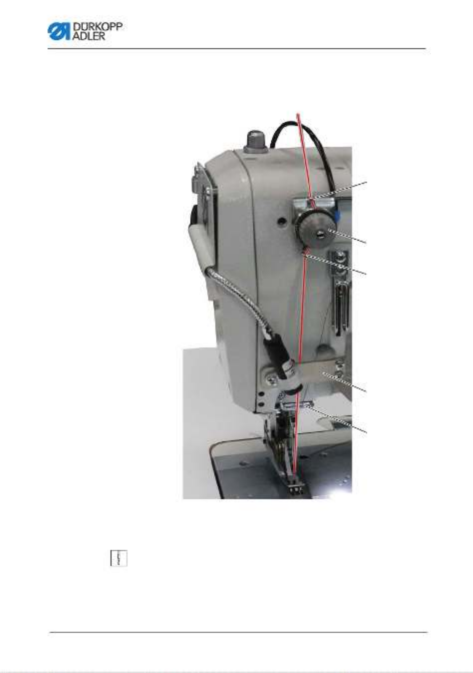
Fig. 6: Threading the needle thread (3)
10. Insert the needle thread through thread guide (15).
11. Insert the needle thread through the needle eye (14) in such
a way that the loose end points downward/faces the hook.
(14)- Needle eye (15)- Thread guide
⑮
⑭
Operation
Operating Instructions 550-12-33/34 - 00.0 - 05/2022 27
4.5 Threading the hook thread
Fig. 7: Threading the hook thread (1)
To thread the needle thread:
1. Fit the thread reel on the right thread reel plate (3).
WARNING
Risk of injury from moving, cutting and sharp
parts!
Crushing, cutting and punctures are possible.
Only thread the hook thread with the machine
switched off.
(1) - Tensioner
(2) - Thread guide
(3) - Right thread reel plate
③
①②
Operation
Operating Instructions 550-12-33/34 - 00.0 - 05/2022 29
10. Pull the hook thread from the rear under the cover plate of
the thread channel (4).
Fig. 9: Threading the hook thread (3)
11. Remove the cover plates to the right and left of the throat
plate (11).
12. Lift the hook thread bobbin case retainer (9) from its latching.
13. Turn the handwheel to position B in such a way that the thread
take-up disk (12) is set accordingly.
14. Insert the hook thread from the right to the left through the
holes of the hook thread guide (13).
15. Turn the handwheel until the hook holes (10) are accessible.
16. Insert the hook thread from the right to the left through the
hook holes (10) before pulling it out towards the rear by
approx. 3 cm.
Fig. 10: Threading the hook thread (4)
(9) - Hook thread bobbin case retainer
(10)- Hook hole
(11) - Throat plate
(12)- Thread take-up disk
(13) - Hook thread guide
⑩
⑪⑬
⑭
⑫

Operation
Operating Instructions 550-12-33/34 - 00.0 - 05/202230
17. Press down and lock into place the hook thread bobbin case
retainer (9).
18. Insert the hook covers again on the left and the right next to
the throat plate (11).
Operation
Operating Instructions 550-12-33/34 - 00.0 - 05/2022 31
4.6 Threading the reinforcement tape
The reinforcement tape is used to reinforce the seam and support
ruffling. The reinforcement tape can be fed in 2 ways:
• Tape feeder at the top (at the machine head)
• Tape feeder at the bottom (under the tabletop)
The machine is equipped with either type of tape feeder. If fed
from the top, the reinforcement tape is sewn on top of the material.
If fed from the bottom, the reinforcement tape is sewn under the
material.
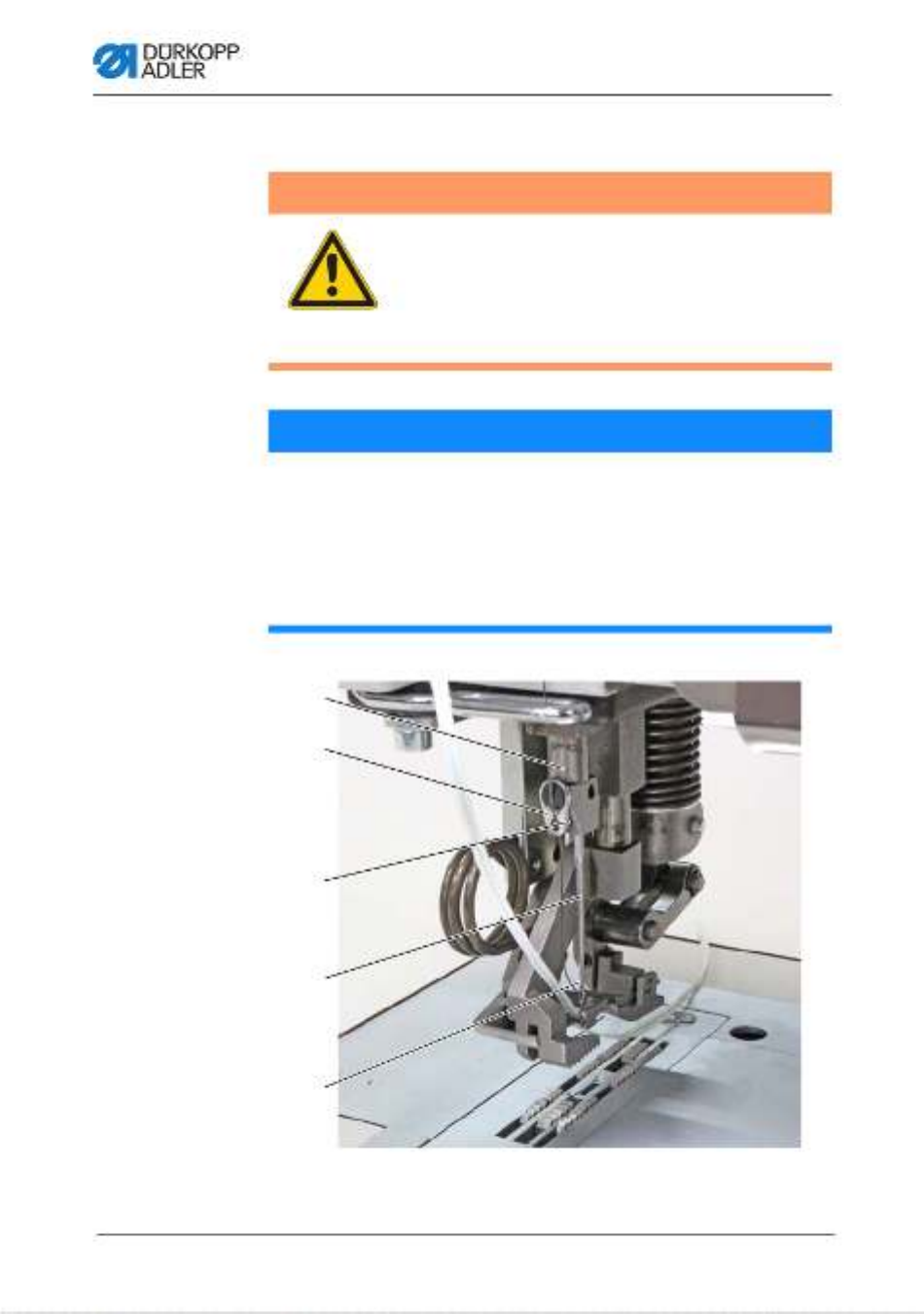
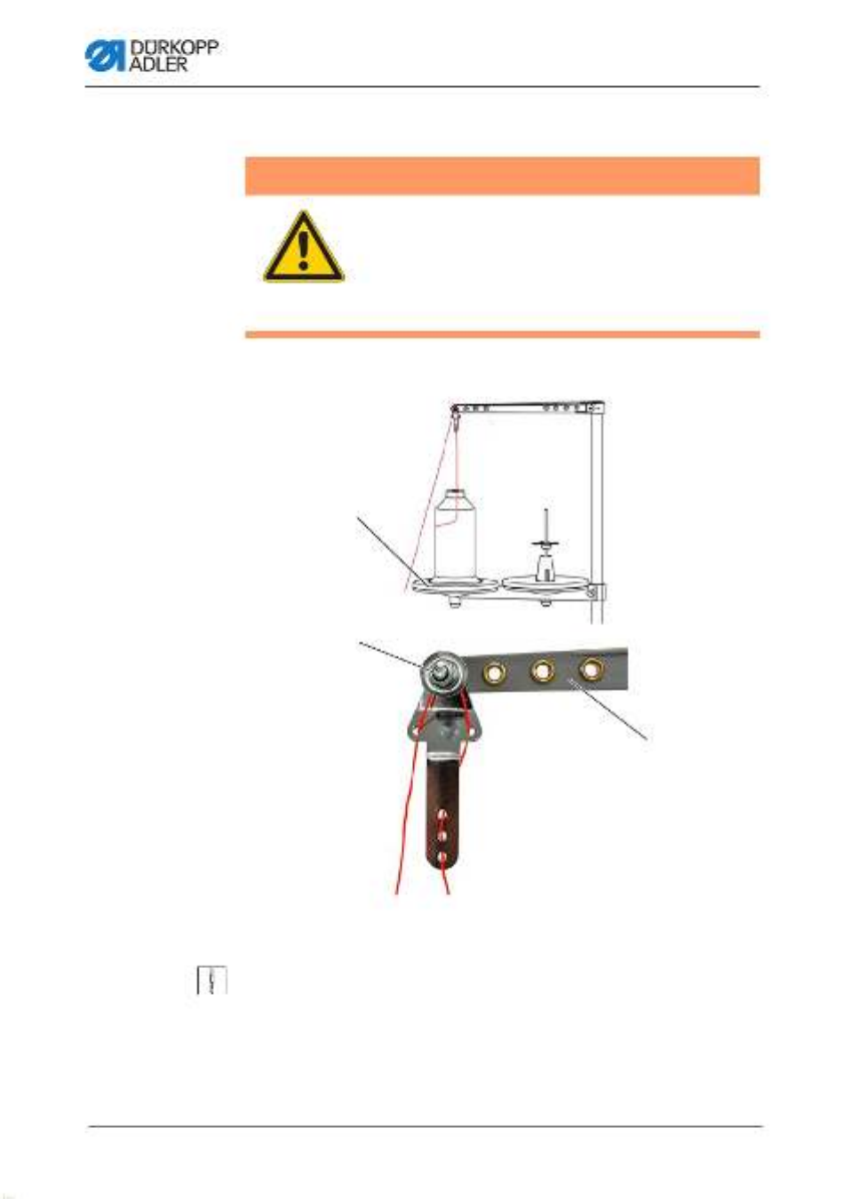
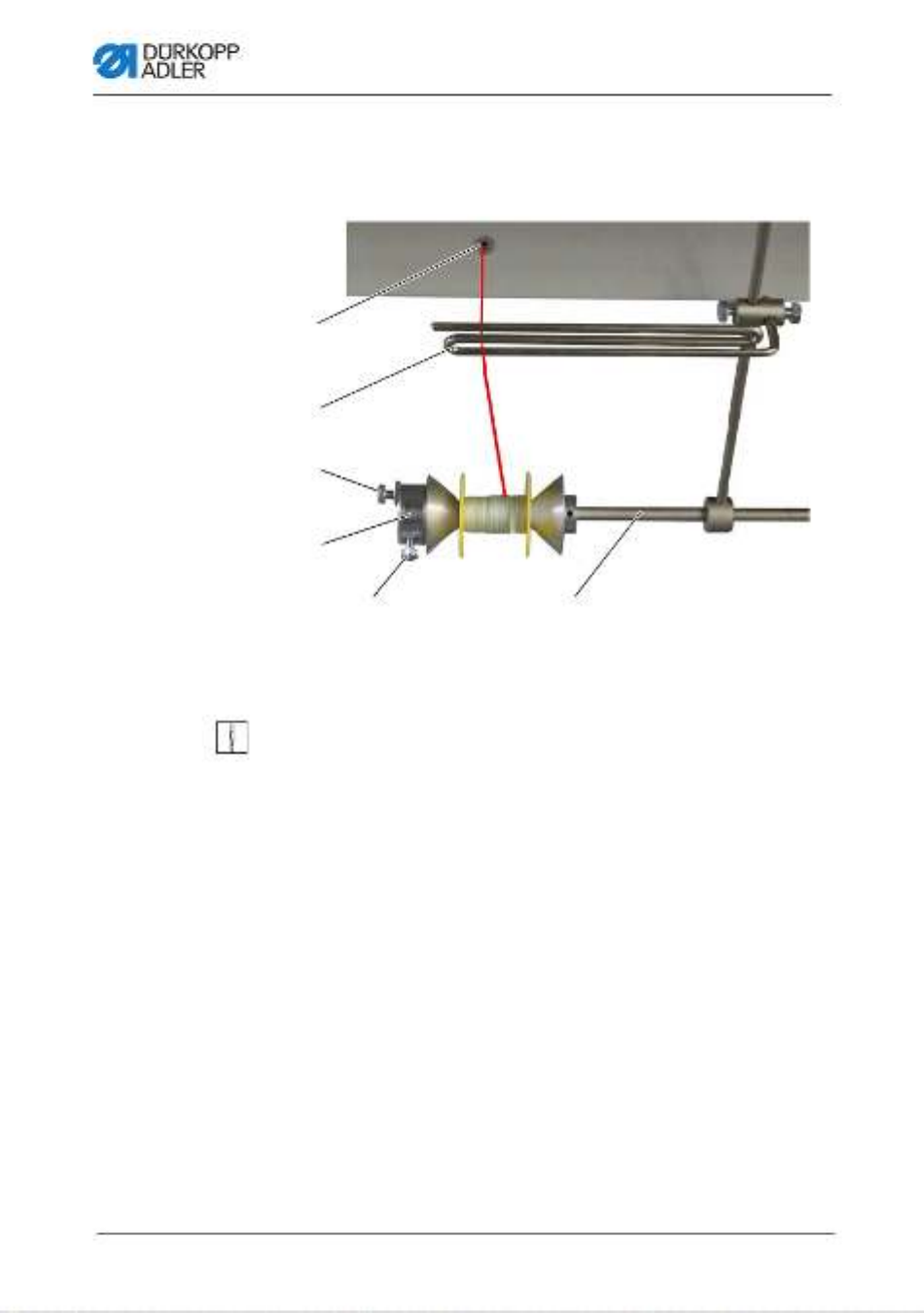
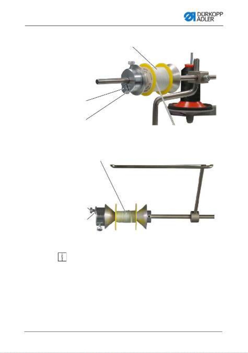
4.6.1 Threading the reinforcement tape from the top
Fig. 11: Threading the reinforcement tape from the top (1)
To thread the reinforcement tape from the top:
1. Loosen the screw (2) and pull it off the bar (1) towards the left
together with the brake element (3).
2. Fit the tape roll onto the bar (1).
3. Slip the brake element (3) back onto the bar (1).
4. Tighten the screw (2).
Now, the tape roll can no longer slip off the bar.
(1) - Bar
(2) - Screw
(3) - Brake element
(4) - Screw
①②③
④
Operation
Operating Instructions 550-12-33/34 - 00.0 - 05/202232
5. Use the screw (4) to set how strongly the tape roll is supposed
to be braked ( p. 46).
Fig. 12: Threading the reinforcement tape from the top (2)
6. Feed the reinforcement tape from the tape roll to the tape
guide (9) and thread it from top to bottom.
7. Feed the reinforcement tape clockwise through the
tensioner (8).
(5) - Thread guide
(6) - Bracket
(7) - Tape guide
(8) - Tensioner
(9) - Tape guide
⑥
⑤
⑦
⑧
⑨
Operation
Operating Instructions 550-12-33/34 - 00.0 - 05/2022 33
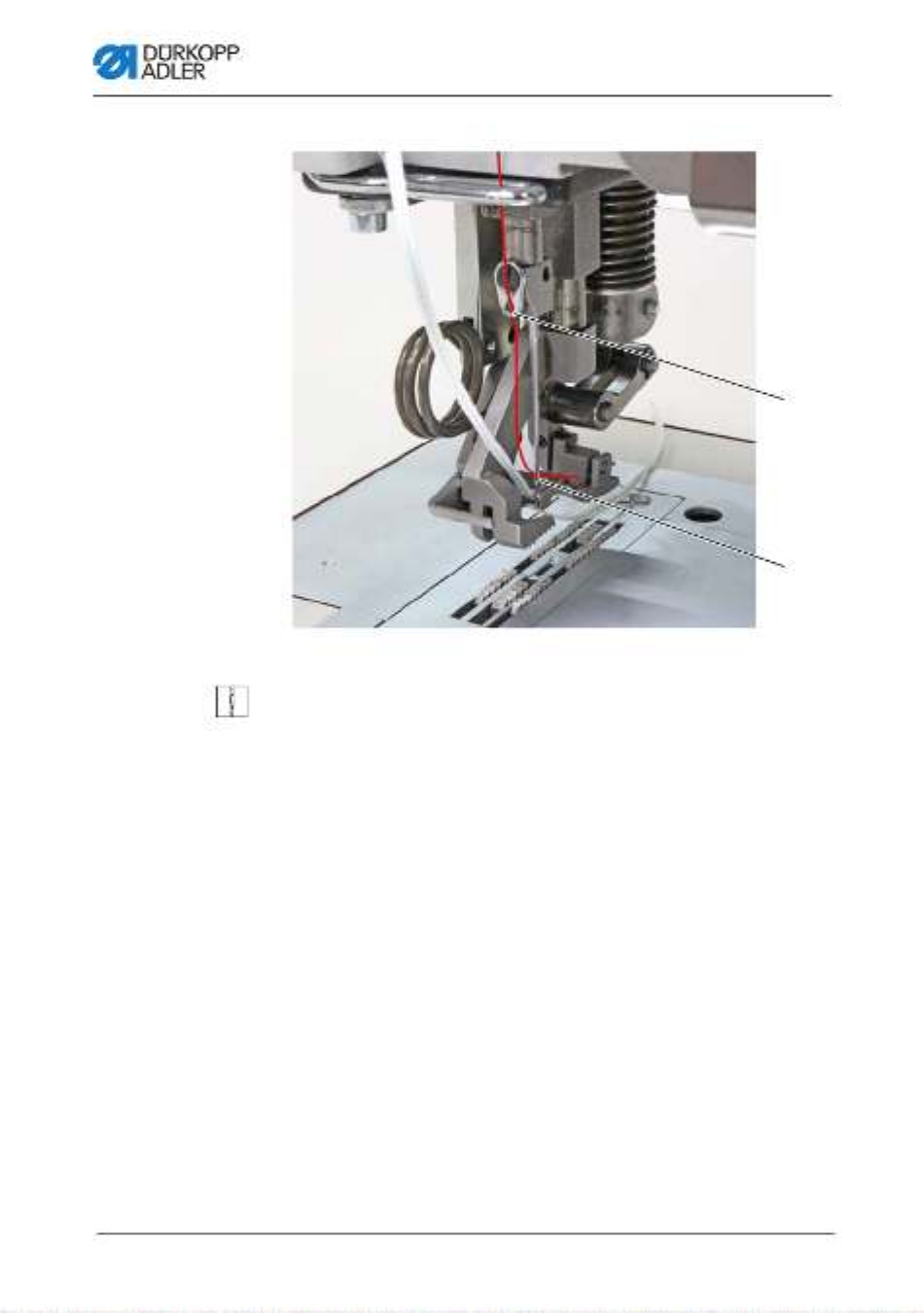
8. Feed the reinforcement tape from top to bottom through the
tape guide (7).
9. Feed the reinforcement tape downwards from the top behind
the bracket (6).
10. Guide the reinforcement tape IN FRONT OF the thread
guide (5) from the top.
DO NOT guide the reinforcement tape behind the thread
guide (5) to keep the reinforcement tape and the needle
thread from becoming entangled.
Fig. 13: Threading the reinforcement tape from the top (3)
11. Feed the reinforcement tape from top to bottom through the
tape guide (10).
The reinforcement tape has been fully threaded from the
top.
12. Guide the reinforcement tape towards the rear in the same
way as the needle thread.
(10)- Tape guide
⑩
Operation
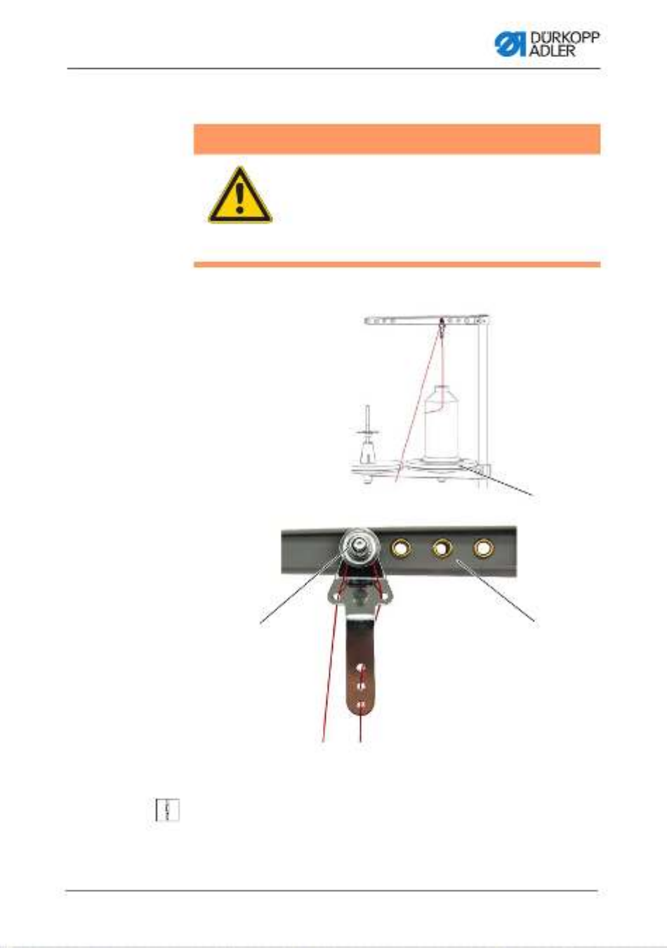
Operating Instructions 550-12-33/34 - 00.0 - 05/202234
4.6.2 Threading the reinforcement tape from
the bottom
Fig. 14: Threading the reinforcement tape from the bottom (1)
To thread the reinforcement tape from the bottom:
1. Loosen the screw (5) and pull it off the bar (6) towards the left
together with the brake element (4).
2. Fit the tape roll onto the bar (6).
3. Slip the brake element (4) back onto the bar (6).
4. Tighten the screw (5).
Now, the tape roll can no longer slip off the bar.
5. Use the screw (3) to set how strongly the tape roll is supposed
to be braked ( p. 46).
6. Feed the reinforcement tape up from the tape roll to the tape
guide (2) and thread it.
7. Tilt the machine head ( p. 134).
8. Feed the reinforcement tape up through the slot in the oil
pan (1).
(1) - Slot in the oil pan
(2) - Tape guide
(3) - Screw
(4) - Brake element
(5) - Screw
(6) - Bar
③
⑤ ⑥
①
②
④
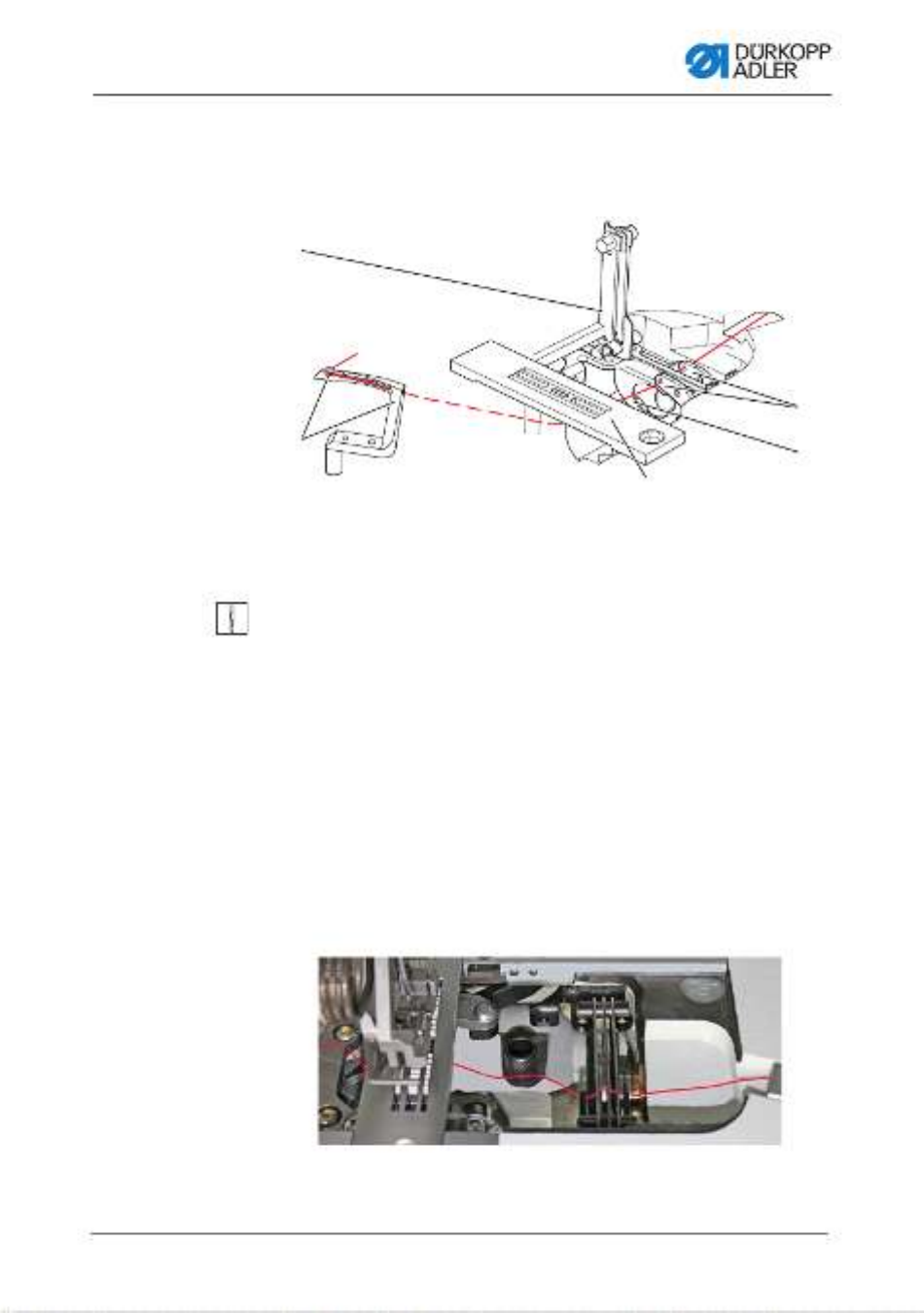
Operation
Operating Instructions 550-12-33/34 - 00.0 - 05/202236
Fig. 16: Threading the reinforcement tape from the bottom (3)
12. Feed the reinforcement tape, as shown, from the bottom
through the throat plate (10).
13. Guide the reinforcement tape towards the rear in the same
way as the needle thread.
14. Erect the machine head again ( p. 134).
Fig. 17: Threading the reinforcement tape from the bottom (4)
15. Loosen the lever (11) to set the rod of the bottom tape guide.
The bottom feeder must not impair free movement during
sewing.
16. Lock the lever (11) back into position.
(10)- Throat plate
(11) - Lever
⑩

Operation
Operating Instructions 550-12-33/34 - 00.0 - 05/2022 37
4.7 Thread tension
Together with the hook thread tension, the needle thread tension
influences the final seam pattern. With thin sewing material,
excessive thread tension can lead to thread breakage.
Proper setting
The needle thread tension must be tighter than the hook thread
tension. To ensure the proper setting, the hook thread tensioner
is equipped with a spring made of thinner wire
Disturbance from incorrectly set thread tension
• Too tight: Crimping of the sewing material
• Too loose: Missing stitches
The thread tension is set at the control panel.
If 100 % thread tension is insufficient, the thread pre-tension can
be supplemented ( p. 43). To this end, the tensioner elements
of the thread pre-tensioner are set closer together. The tensioner
elements of the thread pre-tensioner are, otherwise, always open.
Operation
Operating Instructions 550-12-33/34 - 00.0 - 05/202238
4.7.1 Setting the needle thread quantity
The needle thread quantity released for stitch formation is deter-
mined by the position of the needle thread regulator. The required
needle thread quantity depends on the thickness of the sewing
material, the thread strength, and the seam type.
In addition, the threading procedure varies with the needle threads
and the types of seams used.
Fig. 18: Setting the needle thread quantity (1)
Proper setting
•Less elastic threads:
The thread lever (1) is visible just above the needle thread
regulator when at bottom dead center.
•Very elastic threads:
The thread lever (1) is visible just below the needle thread
regulator when at bottom dead center.
WARNING
Risk of injury from moving parts!
Crushing possible.
Switch off the machine before setting the needle
thread quantity.
(1) - Thread lever
very elastic less elastic
①
Operation
Operating Instructions 550-12-33/34 - 00.0 - 05/202240
4.7.2 Setting the hook thread quantity
The hook thread quantity released is determined by the position
of the hook thread take-up. The hook thread take-up adapts the
hook thread quantity to each set stitch length to allow for the best
possible stitch pull at any length and even with stitch condensing
enabled.
The hook thread take-up can be adjusted continuously on a scale
from 0 5 to . The larger the value, the greater the released thread
quantity and the more elastic the seam.
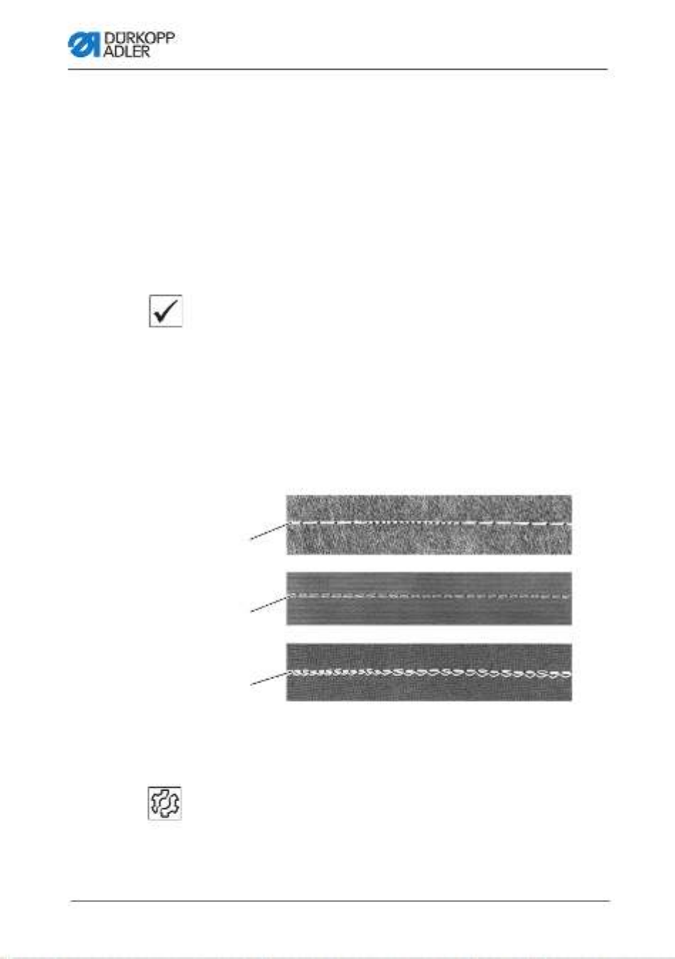
Proper setting
The proper setting is dependent on the stitch length and the seam
type.
You need to ensure, especially when applying extreme settings,
that the needle reliably plunges into the thread triangle:
• Elastic seam (3) with a very short stitch length = scale 5
• Tighter seam (1) with a significantly increased stitch length =
scale 0
Fig. 20: Setting the hook thread quantity (1)
Disturbance if hook thread quantity to too high
• Missing stitches
• Hook thread pops out of the thread take-up disk
(1) - Tight seam
(2) - Normal seam
(3) - Highly elastic seam
(balloon stitch)
①
②
③
Operation
Operating Instructions 550-12-33/34 - 00.0 - 05/2022 41
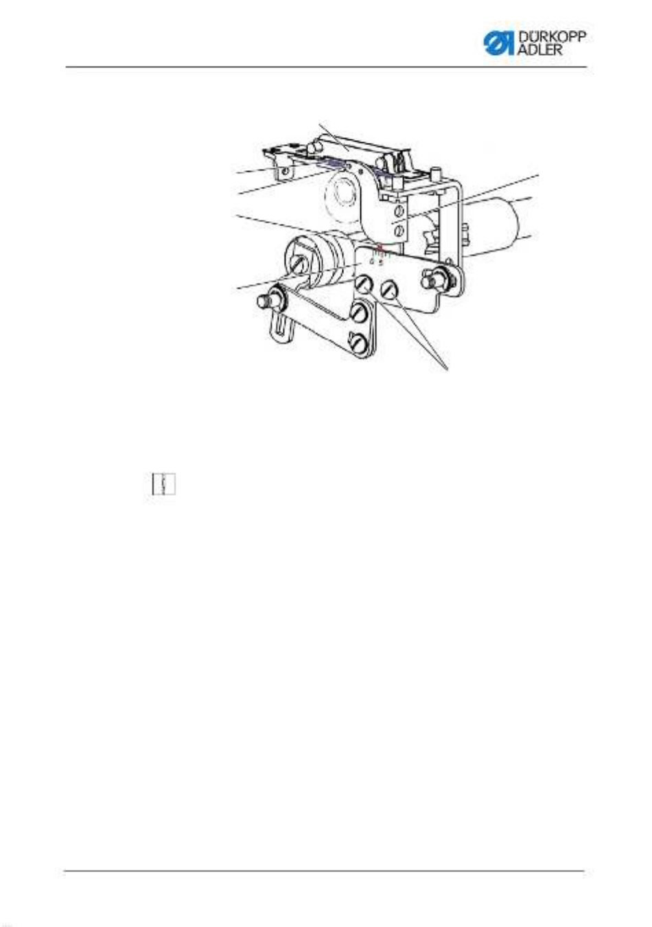
Fig. 21: Setting the hook thread quantity (2)
To set the hook thread quantity:
1. Tilt the machine head ( p. 134).
2. Loosen the screws (9).
3. Move the hook thread take-up (10).
• Tighter seam = move the front edge (7) towards the 0 on
the scale (8)
• More elastic seam = move the front edge (7) towards
the 5 on the scale (8)
(4) - Thread bobbin case retainer
(5) - Lower bar
(6) - Hole
(7) - Front edge
(8) - Scale
(9) - Screw
(10)- Hook thread take-up
④
⑤
⑥
⑨
⑩
⑦
⑧

Operation
Operating Instructions 550-12-33/34 - 00.0 - 05/202242
Important
Fig. 22: Setting the hook thread quantity (3)
Do not alter the height of the hook thread take-up (10).
The hole (6) must always remain above the lower bar (5) of
the thread bobbin case retainer (4).
4. Tighten the screws (9).
5. Erect the machine head ( p. 134).
(4) - Thread bobbin case retainer
(5) - Lower bar
(6) - Hole
(10)- Hook thread take-up
④
⑥
⑤
⑩

Operation
Operating Instructions 550-12-33/34 - 00.0 - 05/202244
Fig. 25: Setting thread pre-tensioner/tape tensioner (3)
To increase the thread pre-tension/tape tension:
1. Turn the tensioner element (1)/(2)/(3)/(4) clockwise in the +
direction.
The tensioner element (1)/(2)/(3)/(4) is closed.
To reduce the thread pre-tension/tape tension:
1. Turn the tensioner element (1)/(2)/(3)/(4) counterclockwise in
the - direction.
The tensioner element (1)/(2)/(3)/(4) is opened.
For information on how to set a larger amount of thread in the
seam, see p. 38.
Information
The tape tensioner for the reinforcement tape is best set when
switched on, allowing you to test the setting directly during sewing.
For instructions on how to turn the tape tensioner of the reinforce-
ment tape on/off, refer to ( p. 45).
(4) - Tensioner element
(lower tape tensioner)
④
Operation
Operating Instructions 550-12-33/34 - 00.0 - 05/2022 45
4.8 Switching the tape tensioner for the
reinforcement tape on/off
Depending on its equipment, the machine may be equipped with
a lower or an upper tape feeder.
Fig. 26: Switching the tape tensioner for the reinforcement tape on/off (1)
Fig. 27: Switching the tape tensioner for the reinforcement tape on/off (2)
On both tape feeders, the reinforcement tape is fed through a
tensioner element (1)/(2), which can be closed and opened as
necessary.
The tape tensioner is switched off for ruffling values of 0 7- .
The tape tensioner is switched on automatically for ruffling values
of 8 and higher; the button (3) will then light up. The tape tensioner
can be switched off at any time.
(1) - Tensioner element (top)
(2) - Tensioner element (bottom)
①
②

Operation
Operating Instructions 550-12-33/34 - 00.0 - 05/202246
The tape tensioner is set in the same way as needle thread pre-
tensioner and hook thread pre-tensioner ( p. 43).
Information
The ruffling value at which the tape tensioner is switched on
automatically can be adjusted on the control panel ( p. 82) and
( p. 99).
4.9 Setting the tape brake
Information
If the reinforcement tape is not sewn straight relative to the seam,
the tape feeder may be too loose and/or the reinforcement tape
tension may be too low.
Ruffling is increased if the tape tension is too high and/or the tape
brake is set too tight.
The reinforcement tape tension can be set by adjusting the tape
tensioner ( p. 45). The tape brake regulates the tape feeder.
Depending on its equipment, the machine may be equipped with
a lower or an upper tape feeder for the reinforcement tape
( p. 31).
To ensure that the reinforcement tape is fed in a way that achieves
straight seam support and the desired ruffling value, the tape brake
must be set accordingly.
The principle that is used to brake the tape feeder is identical for
the upper and the lower feeder.
Operation
Operating Instructions 550-12-33/34 - 00.0 - 05/2022 47
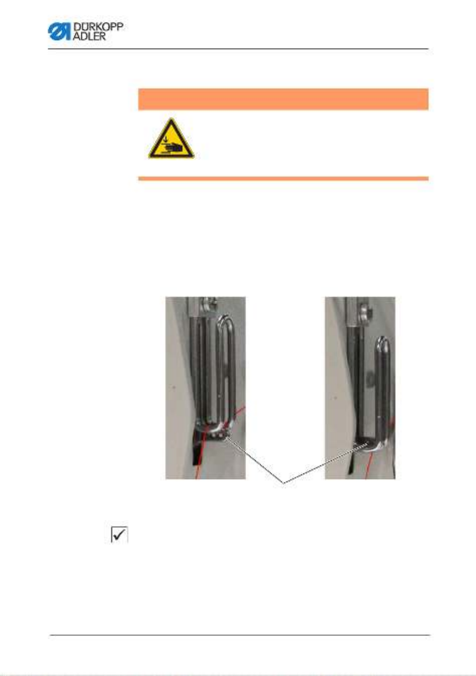
Fig. 28: Setting point in time for cutting (1)
Fig. 29: Setting point in time for cutting (2)
To set the upper/lower tape brake:
1. Loosen the nut (3).
2. To reduce the force of the tape brake, loosen the screw (2).
3. To increase the force of the tape brake, tighten the screw (2).
4. To lock the screw (2) in position, tighten the nut (3).
(1) - Tape roll (top)
(2) - Screw
(3) - Nut
(1) - Tape roll (bottom)
(2) - Screw
(3) - Nut
②
①
③
②
①
③
Operation
Operating Instructions 550-12-33/34 - 00.0 - 05/2022 49
To remove the lock:
1. Press the pedal to position -1.
2. Release the pedal (position 0).
The locking button (1) disengages, canceling the lock.
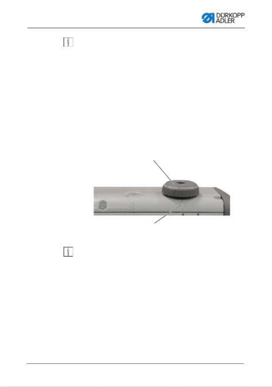
4.11 Setting the sewing foot stroke
The sewing foot stroke is adjustable over a range of 2-7 mm by
turning the adjusting wheel.
The increased sewing foot stroke can be switched on and off using
the left button ( p. 53).
Fig. 31: Setting the stroke height
To set the sewing foot stroke:
1. Set the sewing foot stroke:
• Increase the sewing foot stroke Turn the adjusting
wheel (1) counterclockwise
• Reduce the sewing foot stroke: Turn the adjusting
wheel (1) clockwise
The marking (2) indicates the selected stroke height.
(1) - Adjusting wheel (2) - Marking
①
②
Operation
Operating Instructions 550-12-33/34 - 00.0 - 05/202250
4.12 Setting the sewing foot pressure
Fig. 32: Setting the sewing foot pressure
To set the sewing foot pressure:
1. Loosen the nut (2).
2. Set the sewing foot pressure:
• Increase the sewing foot pressure:
Turn screw (1) clockwise
• Reduce the sewing foot pressure:
Turn screw (1) counterclockwise
3. Tighten the nut (2).
Important
Major changes to the sewing foot pressure require a recalibration
of the ruffling device ( Service Instructions).
NOTICE
Property damage may occur!
Damage to the sewing material.
Set the sewing foot pressure such that the sewing material
can neither slip nor become damaged.
(1) - Screw (2) - Nut
①②

Operation
Operating Instructions 550-12-33/34 - 00.0 - 05/2022 51
4.13 Using the knee button during sewing
The knee button can be used to switch a function on and off during
sewing.
Fig. 33: Using the knee button during sewing (1)
The position of the toggle switch (1) indicates whether the function
is switched on or off.
0 = function is switched off
1 = function is switched on
The function assigned to the knee button (2) at the factory is
Set selected ruffling value to 0 and vice versa.
Information
The knee button (2) can also be assigned other functions via the
technician level on the control panel.
(1) - Toggle switch (2) - Knee button
①
②

Operation
Operating Instructions 550-12-33/34 - 00.0 - 05/202252
Fig. 34: Using the knee button during sewing (2)
To use the knee button during sewing:
1. Press the knee button (2).
The ruffling value is reset to 0.
2. Press the knee button (2) again.
The previous ruffling value is restored.
(2) - Knee button
②

Operation
Operating Instructions 550-12-33/34 - 00.0 - 05/2022 53
4.14 Switching maximum stroke on and off
The maximum stroke can be selected via the control panel
( p. 77).
4.15 Switching the edge cutter on and off
The machine is equipped with an edge cutter. In manual mode,
the edge cutter can be switched on and off at any time. The top
blade is designed such that it will penetrate reliably even if acti-
vated during sewing. The edge cutter can be adjusted via the
control panel ( p. 59).
CAUTION
Risk of injury at exposed blade!
There is a risk of sustaining injuries at the
exposed blades.
Do not reach into the cutting area.

Operation
Operating Instructions 550-12-33/34 - 00.0 - 05/202254
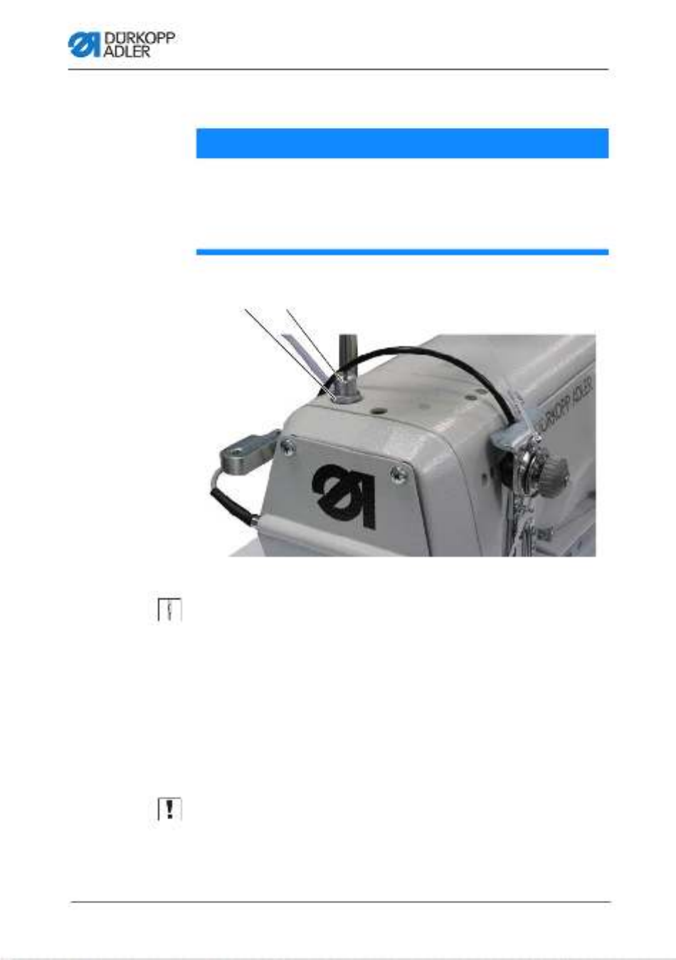
4.16 Switching on and off the sewing lamp
The sewing lamp switches on and off independent of the main
switch.
Fig. 35: Switching on and off the sewing lamp
To switch on the sewing lamp:
1. Set both switches (1) to position I.
The sewing lamp transformer is now powered on.
2. Press the button (6).
The sewing lamp illuminates.
3. Use the (5) or (7) button to set the brightness level.
To switch off the sewing lamp:
1. Press the button (6).
The sewing lamp goes out.
(1) - Switch
(2) - Button
(3) - Button
(4) - Button
(5) - Button
(6) - Button
(7) - Button
②
④
③
⑤
⑦
⑥
①

Operation
Operating Instructions 550-12-33/34 - 00.0 - 05/2022 55
2. Set both switches (1) to position 0.
The sewing lamp transformer is now powered off.
Information
The sewing lamp transformer allows for the connection of a second
LED light. The buttons (2), (3) and (4) are used to switch the
additional LED light on and off and to set the brightness level.
The scope of delivery does not include a second LED light.
4.17 Setting the stitch length
The stitch length is set at the control panel ( p. 59).
In every seam program, the stitch length can be set individually
for each seam section.
Operation
Operating Instructions 550-12-33/34 - 00.0 - 05/202256
4.18 Sewing
Fig. 36: Sewing (1)
The machine offers 2 sewing modes:
• Manual mode
• Automatic mode
Use the pedal to start and control every sewing process.
Initial situation
The pedal is released (position 0).
The machine is at a standstill.
The needle is up, and the sewing feet are down.
WARNING
Risk of injury from moving parts!
Crushing injuries may be sustained while lowering
the sewing feet.
Do NOT put your hands under the lifted sewing
feet.
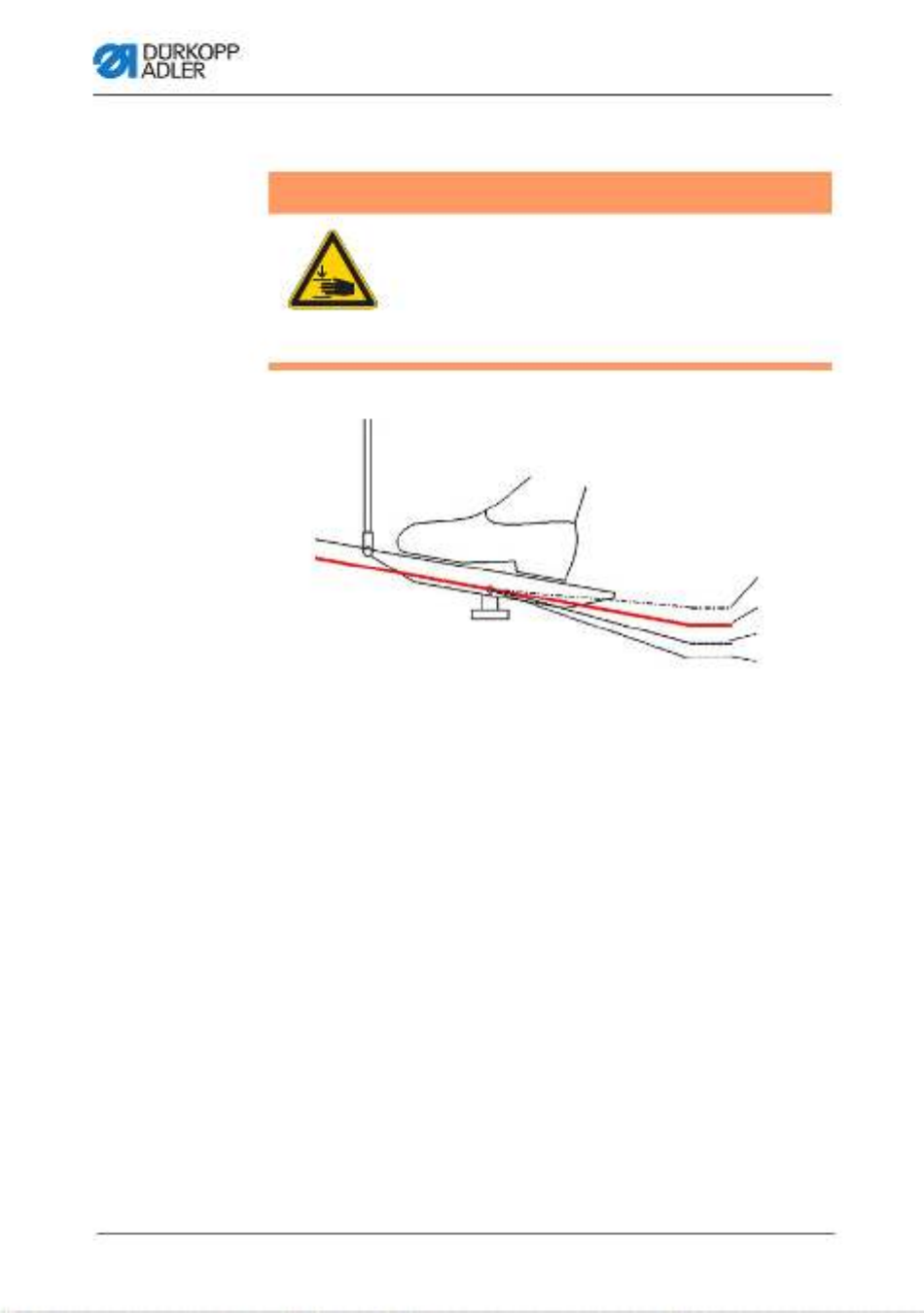
(1) - Position -2
(2) - Position -1
(3) - Position 0
(4) - Position 1
①
④
③
②

Operation
Operating Instructions 550-12-33/34 - 00.0 - 05/2022 57
To position the sewing material:
1. Press the pedal to position -1.
The sewing foot is lifted.
2. Push the sewing material into the initial position.
3. Release the pedal (position 0).
The sewing foot lowers onto the sewing material.
At seam beginning
To start a seam:
1. Press the pedal forward to position 1.
The machine sews. The speed increases the further forward
the pedal is pressed.
During sewing
To interrupt the seam:
1. Release the pedal (position 0).
The machine stops.
Needle and sewing foot are up / down.
To continue the seam:
1. Press the pedal forward to position 1.
The machine continues to sew.
At seam end
To finish the seam:
1. To finish the seam, press the pedal completely backwards to
position -2.
The machine stops.
Needle and sewing feet are lifted and remain up as long as
the pedal is kept in the -2 position.

Operation
Operating Instructions 550-12-33/34 - 00.0 - 05/202258
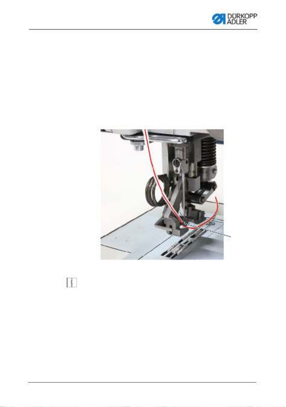
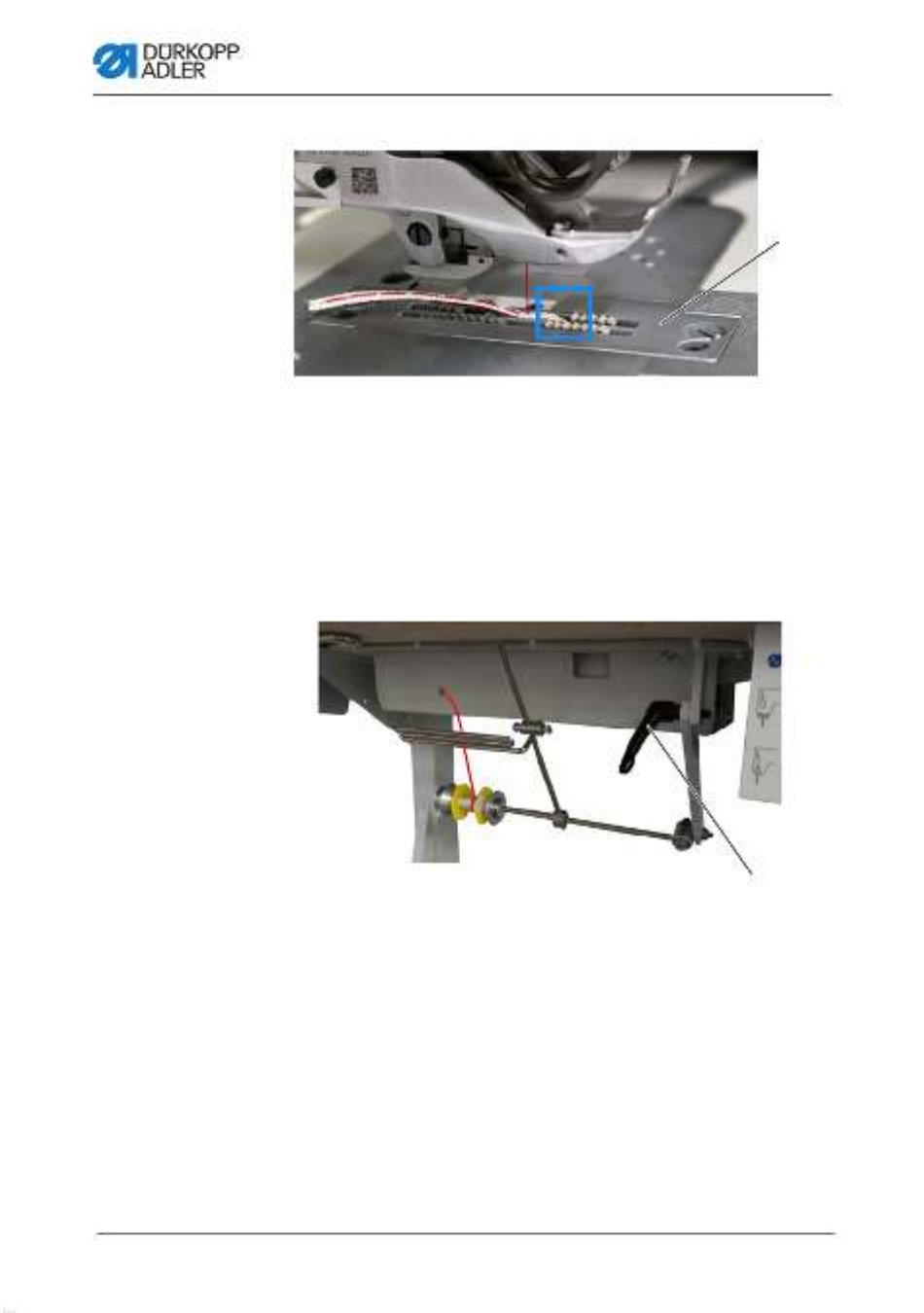
Fig. 37: Sewing (2)
2. Cut the reinforcement tape at the thread-pulling knife (5).
3. Remove the sewing material.
(5) - Thread-pulling knife
⑤

Programming Commander Pro
Operating Instructions 550-12-33/34 - 00.0 - 05/2022 59
5 Programming Commander Pro
5.1 Commander Pro control panel
Fig. 38: Commander Pro control panel
All settings in the software are performed using the Commander
Pro control panel.
Information
If a value is entered that is not within the specified value range,
the software will automatically adopt the limit value which is closest
to your entry from the value range.
5.2 Navigating the Commander Pro control
panel
You navigate the control panel by tapping the screen with your
fingers. There is no need for an input device.
You can open menus by pressing the corresponding button with
your finger. You switch between the different pages of the start
screen by swiping with one finger.

Programming Commander Pro
Operating Instructions 550-12-33/34 - 00.0 - 05/2022 61
Burger menu
A window opens that lets you select Automatic mode,
Manual mode, Programming mode or Settings.
Context-sensitive help
Start by pressing the gray question mark before press-
ing the area for which you need help - this brings up a
pop-up window containing a Help text. Press anywhere
to make the window disappear.
Messages
Bright tiles
Parameters for which you can/must enter a numerical
value. Values can be input by pressing.
Dark tiles (latching)
You can active or deactivate dark tiles encircled by a
white line by tapping. You cannot set any values.
Dark tiles (multifunction)
You can active or deactivate dark tiles encircled by a
white line and showing a blue triangle in the corner by
pressing.
A long press opens a menu that lets you input values.
Dark tiles (hold to run)
You cannot enter any values for dark tiles surrounded
by a square white line. The function assigned to the tile
is only active for as long as you press the tile.
Grayed-out tiles
Grayed-out tiles merely provide information. You can
neither enter values nor active or deactivate these tiles.
Icon Meaning

Programming Commander Pro
72 Operating Instructions 550-12-33/34 - 00.0 - 05/2022
Edit Threading Mode
Edit Light barrier
Edit Reset Bobbin Counter
Edit Seam Center Guide
Automatic mode
Access Program selection
Edit Stitch length correction factor
Edit Needle thread tension correction factor
Sewing
Edit Enable multi functional tiles
Edit Flat Sew
User Management
Edit Current user
Edit Roles up to technician
Edit Users up to technician
Edit Auto Login Editable
Read/Edit/Access Menu item
Termékspecifikációk
| Márka: | Dürkopp Adler |
| Kategória: | varrógép |
| Modell: | 34 |
Szüksége van segítségre?
Ha segítségre van szüksége Dürkopp Adler 34, tegyen fel kérdést alább, és más felhasználók válaszolnak Önnek
Útmutatók varrógép Dürkopp Adler

13 Október 2024
11 Október 2024
6 Október 2024
28 Szeptember 2024
15 Szeptember 2024
14 Szeptember 2024
3 Szeptember 2024
31 Augusztus 2024
31 Augusztus 2024
31 Augusztus 2024
Útmutatók varrógép
- varrógép Husqvarna
- varrógép SilverCrest
- varrógép Singer
- varrógép AEG
- varrógép Emerio
- varrógép Toyota
- varrógép Siemens
- varrógép Medion
- varrógép Carina
- varrógép Prixton
- varrógép Primera
- varrógép Tesco
- varrógép Ambiano
- varrógép Privileg
- varrógép Pfaff
- varrógép Brother
- varrógép Janome
- varrógép Solac
- varrógép Necchi
- varrógép Bernette
- varrógép Juki
- varrógép Guzzanti
- varrógép Baby Lock
- varrógép TriStar
- varrógép Kenmore
- varrógép Husqvarna-Viking
- varrógép Blaupunkt
- varrógép Easy Home
- varrógép Crofton
- varrógép Alfa
- varrógép Veritas
- varrógép Union Special
- varrógép Bernina
- varrógép Bestron
- varrógép Victoria
- varrógép EasyMaxx
- varrógép Anker-Bernette
- varrógép Sinbo
- varrógép Jata
- varrógép Elna
- varrógép Mellerware
- varrógép Termozeta
- varrógép Jocca
- varrógép Yamato
- varrógép Kayser
- varrógép RCE
- varrógép Lifetec
- varrógép Kunft
- varrógép Lervia
- varrógép Vendomatic
- varrógép Home Electric
- varrógép Empisal
- varrógép Lewenstein
- varrógép Durabase
- varrógép Meister Craft
- varrógép Micromaxx
- varrógép Yamata
- varrógép Weasy
- varrógép Łucznik
- varrógép Silver
- varrógép Prince
- varrógép Hofmann
- varrógép Kohler
- varrógép Muller
- varrógép Sinojo
- varrógép Huskystar
- varrógép Gritzner
- varrógép LERAN
- varrógép W6
- varrógép Zippy
- varrógép Feiyue
- varrógép Mediashop
- varrógép ER
- varrógép Novamatic
- varrógép Siemssen
- varrógép Mio Star
- varrógép SteamMax
Legújabb útmutatók varrógép
15 Január 2025
14 Január 2025

14 Január 2025
14 Január 2025
13 Január 2025
12 Január 2025
12 Január 2025
12 Január 2025
12 Január 2025
12 Január 2025