Használati útmutató Draytek Vigor AP 810
Olvassa el alább 📖 a magyar nyelvű használati útmutatót Draytek Vigor AP 810 (177 oldal) a Wifi kategóriában. Ezt az útmutatót 14 ember találta hasznosnak és 2 felhasználó értékelte átlagosan 4.5 csillagra
Oldal 1/177

VigorAP 810 User’s Guide
i

VigorAP 810 User’s Guide ii
V
Vi
ig
go
or
rA
AP
P
8
81
10
0
W
Wi
ir
re
el
le
es
ss
s
A
Ac
cc
ce
es
ss
s
P
Po
oi
in
nt
t
U
Us
se
er
r’
’s
s
G
Gu
ui
id
de
e
Version: 2.2
Firmware Version: V1.2.5
(For future update, please visit DrayTek web site)
Date: September 13, 2018

VigorAP 810 User’s Guide
iii
Copyright Information
Copyright
Declarations
© All rights reserved. This publication contains information that is protected by
copyright. No part may be reproduced, transmitted, transcribed, stored in a retrieval
system, or translated into any language without written permission from the copyright
holders.
Trademarks
The following trademarks are used in this document:
Microsoft is a registered trademark of Microsoft Corp.
Windows, Windows 95, 98, Me, NT, 2000, XP, Vista and Explorer are
trademarks of Microsoft Corp.
Apple and Mac OS are registered trademarks of Apple Inc.
Other products may be trademarks or registered trademarks of their respective
manufacturers.
Safety Instructions and Approval
Safety
Instructions
Read the installation guide thoroughly before you set up the modem.
The modem is a complicated electronic unit that may be repaired only be
authorized and qualified personnel. Do not try to open or repair the modem
yourself.
Do not place the modem in a damp or humid place, e.g. a bathroom.
The modem should be used in a sheltered area, within a temperature range of +5
to +40 Celsius.
Do not expose the modem to direct sunlight or other heat sources. The housing
and electronic components may be damaged by direct sunlight or heat sources.
Do not deploy the cable for LAN connection outdoor to prevent electronic shock
hazards.
Keep the package out of reach of children.
When you want to dispose of the modem, please follow local regulations on
conservation of the environment.
Warranty
We warrant to the original end user (purchaser) that the modem will be free from any
defects in workmanship or materials for a period of two (2) years from the date of
purchase from the dealer. Please keep your purchase receipt in a safe place as it serves
as proof of date of purchase. During the warranty period, and upon proof of purchase,
should the product have indications of failure due to faulty workmanship and/or
materials, we will, at our discretion, repair or replace the defective products or
components, without charge for either parts or labor, to whatever extent we deem
necessary tore-store the product to proper operating condition. Any replacement will
consist of a new or re-manufactured functionally equivalent product of equal value, and
will be offered solely at our discretion. This warranty will not apply if the product is
modified, misused, tampered with, damaged by an act of God, or subjected to abnormal
working conditions. The warranty does not cover the bundled or licensed software of
other vendors. Defects which do not significantly affect the usability of the product will
not be covered by the warranty. We reserve the right to revise the manual and online
documentation and to make changes from time to time in the contents hereof without
obligation to notify any person of such revision or changes.
Be a Registered
Owner Web registration is preferred. You can register your Vigor modem via
http://www.draytek.com.
Firmware & Tools
Updates Due to the continuous evolution of DrayTek technology, all modems will be regularly
upgraded. Please consult the DrayTek web site for more information on newest
firmware, tools and documents.
http://www.draytek.com

VigorAP 810 User’s Guide iv

VigorAP 810 User’s Guide
v
T
Ta
ab
bl
le
e
o
of
f
C
Co
on
nt
te
en
nt
ts
s
Introduction .................................................................................................1
1.1 Introduction ............................................................................................................................. 1
1.2 LED Indicators and Connectors.............................................................................................. 2
1.3 Hardware Installation .............................................................................................................. 4
1.3.1 Wired Connection for PC in LAN...................................................................................... 4
1.3.2 Wired Connection for Notebook in WLAN........................................................................ 5
1.3.3 Wireless Connection......................................................................................................... 6
1.3.4 POE Connection............................................................................................................... 7
Network Configuration................................................................................9
2.1 Windows 7 IP Address Setup..................................................................................................9
2.2 Windows 2000 IP Address Setup...........................................................................................11
2.3 Windows XP IP Address Setup............................................................................................. 12
2.4 Windows Vista IP Address Setup.......................................................................................... 13
2.5 Accessing to Web User Interface.......................................................................................... 14
2.6 Changing Password.............................................................................................................. 15
2.7 Quick Start Wizard ................................................................................................................ 16
2.7.1 Configuring Wireless Settings – General........................................................................ 16
2.7.2 Configuring 2.4GHz Wireless Settings Based on the Operation Mode.......................... 17
2.7.3 Finishing the Wireless Settings Wizard.......................................................................... 24
2.8 Online Status......................................................................................................................... 25
Advanced Configuration.................................................................................27
3.1 Operation Mode .................................................................................................................... 28
3.2 LAN ....................................................................................................................................... 29
3.2.1 General Setup................................................................................................................. 29
3.2.2 Web Portal...................................................................................................................... 32
3.3 Central AP Management.......................................................................................................35
3.3.1 General Setup................................................................................................................. 35
3.3.2 APM Log......................................................................................................................... 36
3.3.3 Function Support List...................................................................................................... 36
3.3.4 Overload Management................................................................................................... 37
3.3.5 Status of Settings............................................................................................................ 38
3.4 General Concepts for Wireless LAN..................................................................................... 39
3.5 Wireless LAN Settings for AP Mode ..................................................................................... 41

VigorAP 810 User’s Guide vi
3.5.1 General Setup................................................................................................................. 42
3.5.2 Security........................................................................................................................... 44
3.5.3 Access Control................................................................................................................ 47
3.5.4 WPS................................................................................................................................ 48
3.5.5 Advanced Setting............................................................................................................ 49
3.5.6 AP Discovery.................................................................................................................. 51
3.5.7 WMM Configuration........................................................................................................ 52
3.5.8 Bandwidth Management................................................................................................. 54
3.5.9 Airtime Fairness.............................................................................................................. 55
3.5.10 Station Control.............................................................................................................. 57
3.5.11 Roaming ....................................................................................................................... 58
3.5.12 Station List.................................................................................................................... 60
3.6 Wireless LAN Settings for Station-Infrastructure Mode.......................................................... 62
3.6.1 General Setup................................................................................................................. 62
3.6.2 Site Survey ..................................................................................................................... 67
3.6.3 Statistics.......................................................................................................................... 68
3.6.4 WPS (Wi-Fi Protected Setup)......................................................................................... 68
3.7 Wireless LAN Settings for AP Bridge-Point to Point/AP Bridge-Point to Multi-Point Mode .. 70
3.7.1 General Setup................................................................................................................. 70
3.7.2 Advanced Setting............................................................................................................ 72
3.7.3 AP Discovery.................................................................................................................. 74
3.7.4 WDS AP Status .............................................................................................................. 76
3.8 Wireless LAN Settings for AP Bridge-WDS Mode ................................................................ 77
3.8.1 General Setup................................................................................................................. 78
3.8.2 Security........................................................................................................................... 81
3.8.3 Access Control................................................................................................................ 84
3.8.4 WPS................................................................................................................................ 85
3.8.5 Advanced Setting............................................................................................................ 86
3.8.6 AP Discovery.................................................................................................................. 88
3.8.7 WDS AP Status .............................................................................................................. 89
3.8.8 WMM Configuration........................................................................................................ 90
3.8.9 Bandwidth Management................................................................................................. 92
3.8.10 Airtime Fairness............................................................................................................ 93
3.8.11 Station Control.............................................................................................................. 95
3.8.12 Roaming ....................................................................................................................... 96
3.8.13 Station List.................................................................................................................... 98
3.9 Wireless LAN Settings for Universal Repeater Mode........................................................... 99
3.9.1 General Setup............................................................................................................... 100
3.9.2 Security......................................................................................................................... 102
3.9.3 Access Control.............................................................................................................. 105
3.9.4 WPS.............................................................................................................................. 106
3.9.5 Advanced Setting.......................................................................................................... 107
3.9.6 AP Discovery................................................................................................................ 110
3.9.7 Universal Repeater....................................................................................................... 111
3.9.8 WMM Configuration...................................................................................................... 114
3.9.9 Bandwidth Management............................................................................................... 116
3.9.10 Airtime Fairness.......................................................................................................... 117
3.9.11 Station Control............................................................................................................ 119
3.9.12 Roaming ..................................................................................................................... 120
3.9.13 Station List.................................................................................................................. 122
3.10 RADIUS Setting ................................................................................................................ 124
3.10.1 RADIUS Server........................................................................................................... 124
3.10.2 Certificate Management ............................................................................................. 125
3.11 Applications ....................................................................................................................... 126

VigorAP 810 User’s Guide
1
I
In
nt
tr
ro
od
du
uc
ct
ti
io
on
n
1
1.
.1
1
I
In
nt
tr
ro
od
du
uc
ct
ti
io
on
n
Thank you for purchasing this VigorAP 810! With this high cost-efficiency VigorAP 810,
computers and wireless devices which are compatible with 802.11n can connect to existing
wired Ethernet network via this VigorAP 810, at the speed of 300Mbps.
Easy install procedures allows any computer users to setup a network environment in very
short time - within minutes, even inexperienced users. Just follow the instructions given in
this user manual, you can complete the setup procedure and release the power of this access
point all by yourself!

VigorAP 810 User’s Guide 2
1
1.
.2
2
L
LE
ED
D
I
In
nd
di
ic
ca
at
to
or
rs
s
a
an
nd
d
C
Co
on
nn
ne
ec
ct
to
or
rs
s
Before you use the Vigor modem, please get acquainted with the LED indicators and
connectors first.
Status Explanation
Off The system is not ready or is failed. ACT
Blinking The system is ready and can work normally.
On A USB device is connected and active. USB
Blinking The data is transmitting.
On A normal connection is through its corresponding
port.
Off LAN is disconnected.
LAN B
Blinking Data is transmitting (sending/receiving).
On A normal connection is through its corresponding
port. LAN A1 - A4
Off LAN is disconnected.
On Press the button and release it within 2 seconds. When the
wireless function is ready, the green LED will be on.
Off Press the button and release it within 2 seconds to turn off
the WLAN function. When the wireless function is not
ready, the LED will be off.
WLAN
(Green LED) on
WLAN button
Blinking
(Green) Data is transmitting (sending/receiving).
WPS
(Orange LED) on
WLAN button
Blinking
(
Orange
)
When WPS function is enabled by web user interface,
press this button for more than 2 seconds to wait for
client’s device making
network connection through WPS.
When the orange LED blinks with 1 second cycle for 2
minutes, it means that the AP is waiting for wireless client
to connect
with it.
USB Connector for a printer.

VigorAP 810 User’s Guide
3
Interface Description
LAN B Connecter for xDSL / Cable modem (Giga level)
or router.
LAN A1 (PoE) -
A4 Connecter for xDSL / Cable modem (Giga level) /
computer or router.
Restore the default settings. Usage: Turn on the
AP. Press the button and keep for more than 6
seconds. Then the AP will restart with the factory
default configuration.
ON/OFF: Power switch.
PWR: Connecter for a power adapter.

VigorAP 810 User’s Guide 4
1
1.
.3
3
H
Ha
ar
rd
dw
wa
ar
re
e
I
In
ns
st
ta
al
ll
la
at
ti
io
on
n
This section will guide you to install the VigorAP 810 through hardware connection and
configure the device’s settings through web browser.
Before starting to configure VigorAP 810, you have to connect your devices correctly.
1
1.
.3
3.
.1
1
W
Wi
ir
re
ed
d
C
Co
on
nn
ne
ec
ct
ti
io
on
n
f
fo
or
r
P
PC
C
i
in
n
L
LA
AN
N
1. Connect VigorAP 810 to ADSL modem, router, or switch/hub in your network through
the LAN A port of the access point by Ethernet cable.
2. Connect a computer to other available LAN A port. Make sure the subnet IP address of
the PC is the same as VigorAP 810 management IP, e.g., 192.168.1.X.
3. Connect the A/C power adapter to the wall socket, and then connect it to the PWR
connector of the access point.
4. Power on VigorAP 810.
5. Check all LEDs on the front panel. ACT LED should blink and LAN LEDs should be
on if the access point is correctly connected to the ADSL modem or router.
(For the detailed information of LED status, please refer to section 1.2.)

VigorAP 810 User’s Guide
5
1
1.
.3
3.
.2
2
W
Wi
ir
re
ed
d
C
Co
on
nn
ne
ec
ct
ti
io
on
n
f
fo
or
r
N
No
ot
te
eb
bo
oo
ok
k
i
in
n
W
WL
LA
AN
N
1. Connect VigorAP 810 to ADSL modem or router in your network through the LAN A
port of the access point by Ethernet cable.
2. Connect the A/C power adapter to the wall socket, and then connect it to the PWR
connector of the access point.
3. Power on VigorAP 810.
4. Check all LEDs on the front panel. ACT LED should be steadily on, LAN LEDs
should be on if the access point is correctly connected to the ADSL modem or router.
(For the detailed information of LED status, please refer to section 1.2.)

VigorAP 810 User’s Guide 6
1
1.
.3
3.
.3
3
W
Wi
ir
re
el
le
es
ss
s
C
Co
on
nn
ne
ec
ct
ti
io
on
n
VigorAP 810 can access Internet via an ADSL modem, router, or switch/hub in your
network through wireless connection.
1. Connect VigorAP 810 to ADSL modem or router via wireless network.
2. Connect the A/C power adapter to the wall socket, and then connect it to the PWR
connector of the access point.
3. Power on VigorAP 810.
4. Check all LEDs on the front panel. ACT LED should be steadily on, LAN LEDs
should be on if VigorAP 810 is correctly connected to the ADSL modem, router or
switch/hub.
(For the detailed information of LED status, please refer to section 1.2.)

VigorAP 810 User’s Guide
7
1
1.
.3
3.
.4
4
P
PO
OE
E
C
Co
on
nn
ne
ec
ct
ti
io
on
n
VigorAP 810 can gain the power from the connected switch, e.g., VigorSwitch P2260. PoE
(Power over Ethernet) can break the install limitation caused by the fixed power supply.
1. Connect VigorAP 810 to a switch in your network through the LAN A1 (PoE) port of
the access point by Ethernet cable.
2. Connect a computer to VigorSwitch P2260. Make sure the subnet IP address of the PC
is the same as VigorAP 810 management IP, e.g., 192.168.1.X.
3. Power on VigorAP 810.
4. Check all LEDs on the front panel. ACT LED should be steadily on, LAN LEDs
should be on if the access point is correctly connected to the ADSL modem, router or
switch/hub.

VigorAP 810 User’s Guide 8
This page is left blank.
VigorAP 810 User’s Guide
9
N
Ne
et
tw
wo
or
rk
k
C
Co
on
nf
fi
ig
gu
ur
ra
at
ti
io
on
n
After the network connection is built, the next step you should do is setup VigorAP 810 with
proper network parameters, so it can work properly in your network environment.
Before you can connect to the access point and start configuration procedures, your
computer must be able to get an IP address automatically (use dynamic IP address). If it’s set
to use static IP address, or you’re unsure, please follow the following instructions to
configure your computer to use dynamic IP address:
For the default IP address of this AP is set “192.168.1.2”, we recommend you to use
“192.168.1.X (except 2)” in the field of IP address on this section for your computer.
If the operating system of your computer is…
Windows 7 - please go to section 2.1
Windows 2000 - please go to section 2.2
Windows XP - please go to section 2.3
Windows Vista - please go to section 2.4
2
2.
.1
1
W
Wi
in
nd
do
ow
ws
s
7
7
I
IP
P
A
Ad
dd
dr
re
es
ss
s
S
Se
et
tu
up
p
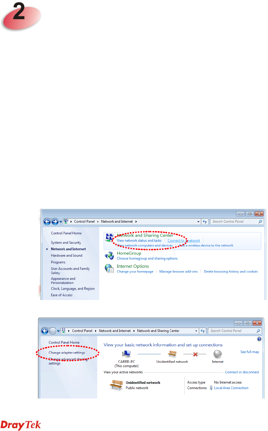
Click Start button (it should be located at lower-left corner of your computer), then click
Control Panel. Double-click Network and Internet, and the following window will appear.
Click Network and Sharing Center.
Next, click Change adapter settings and click Local Area Connection.

VigorAP 810 User’s Guide 10
Then, select Internet Protocol Version 4 (TCP/IPv4) and click Properties.
Under the General tab, click Use the following IP address. Then input the following
settings in respective field and click OK when finish.
IP address: 192.168.1.9
Subnet Mask: 255.255.255.0

VigorAP 810 User’s Guide
11
2
2.
.2
2
W
Wi
in
nd
do
ow
ws
s
2
20
00
00
0
I
IP
P
A
Ad
dd
dr
re
es
ss
s
S
Se
et
tu
up
p
Click Start button (it should be located at lower-left corner of your computer), then click
control panel. Double-click Network and Dial-up Connections icon, double click Local
Area Connection, and Local Area Connection Properties window will appear. Select
Internet Protocol (TCP/IP), then click Properties.
Select Use the following IP address, then input the following settings in respective field and
click OK when finish.
IP address: 192.168.1.9
Subnet Mask: 255.255.255.0

VigorAP 810 User’s Guide 12
2
2.
.3
3
W
Wi
in
nd
do
ow
ws
s
X
XP
P
I
IP
P
A
Ad
dd
dr
re
es
ss
s
S
Se
et
tu
up
p
Click Start button (it should be located at lower-left corner of your computer), then click
control panel. Double-click Network and Internet Connections icon, click Network
Connections, and then double-click Local Area Connection, Local Area Connection
Status window will appear, and then click Properties.
Select Use the following IP address, then input the following settings in respective field and
click OK when finish:
IP address: 192.168.1.9
Subnet Mask: 255.255.255.0.

VigorAP 810 User’s Guide
13
2
2.
.4
4
W
Wi
in
nd
do
ow
ws
s
V
Vi
is
st
ta
a
I
IP
P
A
Ad
dd
dr
re
es
ss
s
S
Se
et
tu
up
p
Click Start button (it should be located at lower-left corner of your computer), then click
control panel. Click View Network Status and Tasks, then click Manage Network
Connections. Right-click Local Area Netwrok, then select ‘Properties’. Local Area
Connection Properties window will appear, select Internet Protocol Version 4 (TCP /
IPv4), and then click Properties.
Select Use the following IP address, then input the following settings in respective field and
click OK when finish:
IP address: 192.168.1.9
Subnet Mask: 255.255.255.0.

VigorAP 810 User’s Guide 14
2
2.
.5
5
A
Ac
cc
ce
es
ss
si
in
ng
g
t
to
o
W
We
eb
b
U
Us
se
er
r
I
In
nt
te
er
rf
fa
ac
ce
e
All functions and settings of this access point must be configured via web user interface.
Please start your web browser (e.g., IE).
1. Make sure your PC connects to the VigorAP 810 correctly.
2. Open a web browser on your PC and type http://192.168.1.2. A pop-up window will
open to ask for username and password. Pease type “admin/admin” on
Username/Password and click OK.
Note 1: You may either simply set up your computer to get IP dynamically from the
router or set up the IP address of the computer to be in the same subnet as the IP
address of VigorAP 810.
If there is no DHCP server on the network, then VigorAP 810 will have an IP
address of 192.168.1.2.
If there is DHCP available on the network, then VigorAP 810 will receive it’s
IP address via the DHCP server.
3. The Main Screen will pop up.

VigorAP 810 User’s Guide
15
Note: If you fail to access to the web configuration, please go to “Trouble
Shooting” for detecting and solving your problem. For using the device properly, it
is necessary for you to change the password of web configuration for security and
adjust primary basic settings.
2
2.
.6
6
C
Ch
ha
an
ng
gi
in
ng
g
P
Pa
as
ss
sw
wo
or
rd
d
1. Please change the password for the original security of the modem.
2. Go to System Maintenance page and choose Administration Password.
3. Enter the new login password on the field of Password. Then click OK to continue.
4. Now, the password has been changed. Next time, use the new password to access the
Web User Interface for this modem.

VigorAP 810 User’s Guide 16
2
2.
.7
7
Q
Qu
ui
ic
ck
k
S
St
ta
ar
rt
t
W
Wi
iz
za
ar
rd
d
Quick Start Wizard will guide you to configure 2.4G wireless setting, 5G wireless setting
and other corresponding settings for Vigor Access Point step by step.
2
2.
.7
7.
.1
1
C
Co
on
nf
fi
ig
gu
ur
ri
in
ng
g
W
Wi
ir
re
el
le
es
ss
s
S
Se
et
tt
ti
in
ng
gs
s
–
–
G
Ge
en
ne
er
ra
al
l
This page displays general settings for the operation mode selected.
Available settings are explained as follows:
Item Description
Operation Mode There are six operation modes for wireless connection. Settings
for each mode are different.
After finishing this web page configuration, please click Next to continue.

VigorAP 810 User’s Guide
17
2
2.
.7
7.
.2
2
C
Co
on
nf
fi
ig
gu
ur
ri
in
ng
g
2
2.
.4
4G
GH
Hz
z
W
Wi
ir
re
el
le
es
ss
s
S
Se
et
tt
ti
in
ng
gs
s
B
Ba
as
se
ed
d
o
on
n
t
th
he
e
O
Op
pe
er
ra
at
ti
io
on
n
M
Mo
od
de
e
In this page, the advanced settings will vary according to the operation mode chosen on
2.7.1.
S
Se
et
tt
ti
in
ng
gs
s
f
fo
or
r
A
AP
P
When you choose AP as the operation mode for wireless LAN (2.4GHz), you will need to
configure the following page.
Available settings are explained as follows:
Item Description
Channel Means the channel frequency of the wireless LAN. The default
channel is 6. You may switch channel if the selected channel is
under serious interference. If you have no idea of choosing the
frequency, please select AutoSelect to let system determine for
you.
Main SSID Set a name for VigorAP to be identified.
Security Key Type 8~63 ASCII characters, such as 012345678..(or 64
Hexadecimal digits leading by 0x, such as "0x321253abcde...").
Enable Guest
Wireless Check the box to enable the guest wireless setting.
Such feature is especially useful for free Wi-Fi service. For
example, a coffee shop offers free Wi-Fi service for its guests
for one hour every day.
SSID – Set a name for VigorAP which can be identified and
connected by wireless guest.

VigorAP 810 User’s Guide 18
Security Key – Set 8~63 ASCII characters or 8~63 ASCII
characters which can be used for logging into VigorAP by
wireless guest.
Enable Bandwidth Limit – Check the box to define the
maximum speed of the data uploading/downloading which will
be used for the guest connecting to Vigor device with the same
SSID.
Upload Limit – Scroll the radio button to choose the
value you want.
Download Limit –Scroll the radio button to choose
the value you want.
Enable Station Control – Check the box to set the duration for
the guest connecting /reconnecting to Vigor device.
Connection Time –Scroll the radio button to choose
the value you want.
Reconnection Time –Scroll the radio button to
choose the value you want.
After finishing this web page configuration, please click Next to continue.
VigorAP 810 User’s Guide
19
S
Se
et
tt
ti
in
ng
gs
s
f
fo
or
r
A
AP
P
B
Br
ri
id
dg
ge
e-
-P
Po
oi
in
nt
t
t
to
o
P
Po
oi
in
nt
t
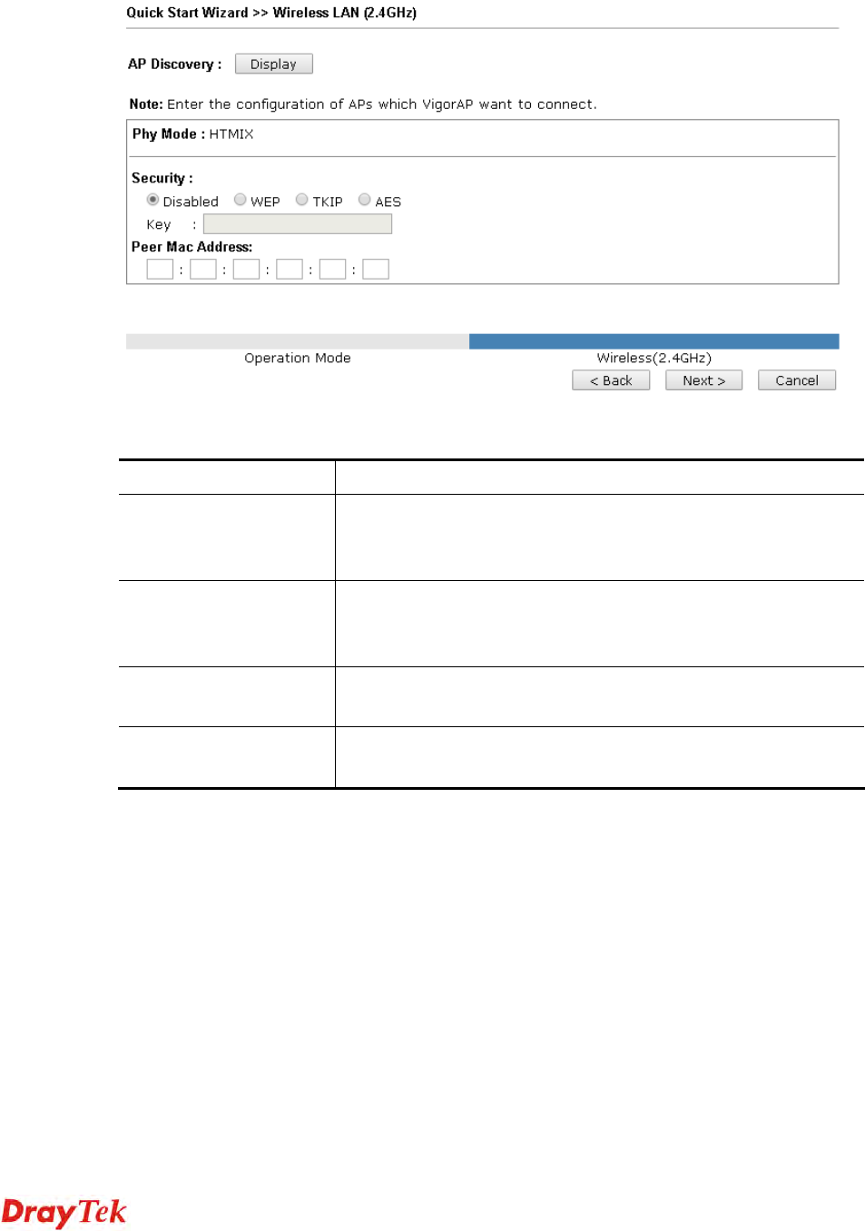
When you choose AP Bridge- Point to Point as Operation Mode and click Next, you will
need to configure the following page:
Available settings are explained as follows:
Item Description
AP Discovery Click this button to open the AP Discovery dialog. VigorAP
can scan all regulatory channels and find working APs in the
neighborhood.
Phy Mode Data will be transmitted via HTMIX communication channel.
Each access point should be setup to the same Phy mode for
connecting with each other.
Security Select WEP, TKIP or AES as the encryption algorithm. Type
the
key number if required.
Peer MAC Address Type the peer MAC address for the access point that VigorAP
810 connects to.

VigorAP 810 User’s Guide 20
S
Se
et
tt
ti
in
ng
gs
s
f
fo
or
r
A
AP
P
B
Br
ri
id
dg
ge
e-
-W
WD
DS
S
When you choose AP Bridge- WDS as Operation Mode and click Next, you will need to
configure the following page:
Available settings are explained as follows:
Item Description
AP Discovery Click this button to open the AP Discovery dialog. VigorAP
can scan all regulatory channels and find working APs in the
neighborhood.
Phy Mode Data will be transmitted via HTMIX communication channel.
Each access point should be setup to the same Phy mode for
connecting with each other.
Security Select WEP, TKIP or AES as the encryption algorithm. Type
the
key number if required. Or, you can click Disable to
disable the
function.
Peer MAC Address Type the peer MAC address for the access point that VigorAP
810 connects to.
Main SSID Set a name for VigorAP to be identified.
Security Key Type 8~63 ASCII characters, such as 012345678..(or 64
Hexadecimal digits leading by 0x, such as
"0x321253abcde...").

VigorAP 810 User’s Guide
21
A
Ad
dv
va
an
nc
ce
ed
d
S
Se
et
tt
ti
in
ng
gs
s
f
fo
or
r
U
Un
ni
iv
ve
er
rs
sa
al
l
R
Re
ep
pe
ea
at
te
er
r
When you choose Bridge-Universal Repeater as Operation Mode and click Next, you
will
need to configure the following page:
Available settings are explained as follows:
Item Description
Universal Repeater Parameters
AP Discovery Click this button to open the AP Discovery dialog. VigorAP
can scan all regulatory channels and find working APs in the
neighborhood.
SSID / MAC Address
(Optional) SSID means the identification of the wireless LAN. After
choosing one of the AP from AP Discovery window and
clicking OK, the settings (SSID and MAC Address) related to
the selected AP will be displayed on these fields automatically.
Later, VigorAP will be allowed to access Internet through the
selected AP, by using SSID displayed here.
Channel Means the channel frequency of the wireless LAN. The default
channel is 6. You may switch channel if the selected channel is
under serious interference.
Security Mode There are several modes provided for you to choose. Each
mode
will bring up different parameters (e.g., WEP keys, Pass
Phrase)
for you to configure.
VigorAP 810 User’s Guide 22
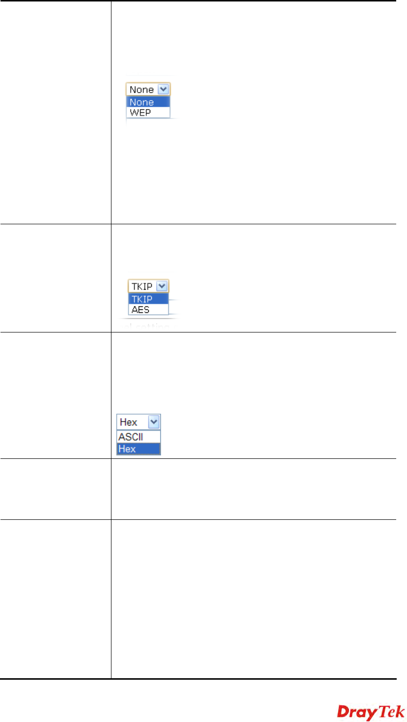
Encryption Type for
Open/Shared This option is available when Open/Shared is selected as
Security Mode.
Choose None to disable the WEP Encryption. Data sent to the
AP will not be encrypted. To enable WEP encryption for data
transmission, please choose WEP.
WEP Keys - Four keys can be entered here, but only one key
can be selected at a time. The format of WEP Key is restricted
to
5 ASCII characters or 10 hexadecimal values in 64-bit
encryption level, or restricted to 13 ASCII characters or 26
hexadecimal values in 128-bit encryption level. The allowed
content is the ASCII characters from 33(!) to 126(~) except '#'
and ','.
Encryption Type for
WPA/PSK and
WPA2/PSK
This option is available when WPA/PSK or WPA2/PSK is
selected as Security Mode.
Select TKIP or AES as the algorithm for WPA.
WEP Keys Four keys can be entered here, but only one key can be selected
at a time. The format of WEP Key is restricted to 5 ASCII
characters or 10 hexadecimal values in 64-bit encryption level,
or restricted to 13 ASCII characters or 26 hexadecimal values
in
128-bit encryption level. The allowed content is the ASCII
characters from 33(!) to 126(~) except '#' and ','.
Security Key Type 8~63 ASCII characters, such as 012345678..(or 64
Hexadecimal digits leading by 0x, such as
"0x321253abcde..."). Such feature is available for
WPA/PSK or WPA2/PSK mode.
Use the same SSID
and Security Key as
above
In general, under the network environment, same SSID and
security key can be used for the host (wireless client) and the
repeater (VigorAP) in Universal Repeater mode. Check it to
use the same SSID and security key configured as above.
SSID - SSID can be any text numbers or various special
characters. For VigorAP is set as “Repeater”, the purpose of
the device is to extend the Wi-Fi service. Therefore, the
characters set here will be regarded as “main SSID”. Other
wireless client can receive the wireless signal from VigorAP
by using the SSID configured here.
Security - Set 8~63 ASCII characters or 64 Hexadecimal digits
which can be used for logging into VigorAP by other wireless

VigorAP 810 User’s Guide
23
client.
Enable Guest
Wireless Check the box to enable the guest wireless setting.
SSID – Set a name for VigorAP. Wireless guest is allowed to
access into Internet via VigorAP with the SSID configured
here.
Security Key – Set 8~63 ASCII characters or 64 Hexadecimal
digits which can be used for logging into VigorAP by wireless
guest.
Enable Bandwidth Limit – Check the box to define the
maximum speed of the data uploading/downloading which will
be used for the guest connecting to Vigor device with the same
SSID.
Upload Limit –Scroll the radio button to choose the
value you want.
Download Limit –Scroll the radio button to choose
the value you want.
Enable Station Control – Check the box to set the duration
for the guest connecting /reconnecting to Vigor device.
Connection Time –Scroll the radio button to
choose the value you want.
Reconnection Time –Scroll the radio button to choose the
value you want.

VigorAP 810 User’s Guide 24
2
2.
.7
7.
.3
3
F
Fi
in
ni
is
sh
hi
in
ng
g
t
th
he
e
W
Wi
ir
re
el
le
es
ss
s
S
Se
et
tt
ti
in
ng
gs
s
W
Wi
iz
za
ar
rd
d
When you see this page, it means the wireless setting wizard is almost finished. Just click
Finish to save the settings and complete the setting procedure.

VigorAP 810 User’s Guide
25
2
2.
.8
8
O
On
nl
li
in
ne
e
S
St
ta
at
tu
us
s
The online status shows the LAN status, Station Link Status for such device.
Detailed explanation is shown below:
Item Description
IP Address Displays the IP address of the LAN interface.
TX Packets Displays the total transmitted packets at the LAN interface.
RX Packets Displays the total number of received packets at the LAN
interface.
TX Bytes Displays the total transmitted size at the LAN interface.
RX Bytes Displays the total number of received size at the LAN interface.

VigorAP 810 User’s Guide 26
This page is left blank.

VigorAP 810 User’s Guide
27
A
Ad
dv
va
an
nc
ce
ed
d
C
Co
on
nf
fi
ig
gu
ur
ra
at
ti
io
on
n
This chapter will guide users to execute advanced (full) configuration.
1. Open a web browser on your PC and type http://192.168.1.2. The window will ask for
typing username and password.
2. Please type “admin/admin” on Username/Password for administration operation.
Now, the Main Screen will appear. Be aware that “Admin mode” will be displayed on the
bottom left side.

VigorAP 810 User’s Guide 28
3
3.
.1
1
O
Op
pe
er
ra
at
ti
io
on
n
M
Mo
od
de
e
This page provides several available modes for you to choose for different conditions. Click
any one of them and click OK. The system will configure the required settings
automatically.
Available settings are explained as follows:
Item Description
AP This mode allows wireless clients to connect to access point and
exchange data with the devices connected to the wired network.
Station-Infrastructure Enable the Ethernet device such as TV and Game player
connected to the VigorAP 810 to an access point.
AP Bridge-Point to
Point This mode can establish wireless connection with another
VigorAP 810 using the same mode, and link the wired network
which these two VigorAP 810s connected together. Only one
access point can be connected in this mode.
AP Bridge-Point to
Multi-Point This mode can establish wireless connection with other VigorAP
810s using the same mode, and link the wired network which
these VigorAP 810s connected together. Up to 4 access points
can be connected in this mode.
AP Bridge-WDS This mode is similar to AP Bridge to Multi-Point, but access
point is not work in bridge-dedicated mode, and will be able to
accept wireless clients while the access point is working as a
wireless bridge.
Universal Repeater This product can act as a wireless range extender that will help
you to extend the networking wirelessly. The access point can
act as Station and AP at the same time. It can use Station
function to connect to a Root AP and use AP function to service

VigorAP 810 User’s Guide
29
all wireless clients within its coverage.
Note: The Wireless LAN settings will be changed according to the Operation Mode
selected here. For the detailed information, please refer to the section of Wireless LAN.
3
3.
.2
2
L
LA
AN
N
Local Area Network (LAN) is a group of subnets regulated and ruled by modem.
3
3.
.2
2.
.1
1
G
Ge
en
ne
er
ra
al
l
S
Se
et
tu
up
p
Click LAN to open the LAN settings page and choose General Setup.
Note: Such page will be changed according to the Operation Mode selected. The
following screen is obtained by choosing AP as the operation mode.
Available settings are explained as follows:
Item Description
LAN-A IP Network
Configuration Enable DHCP Client – When it is enabled, VigorAP will be
treated as a client and can be managed / controlled by AP
Management server offered by Vigor router (e.g., Vigor2860).
IP Address – Type in private IP address for connecting to a local
private network (Default: 192.168.1.2).
Subnet Mask – Type in an address code that determines the size
of the network. (Default: 255.255.255.0/ 24)

VigorAP 810 User’s Guide
31
server IP address here because your ISP often provides you
more than one DNS Server. If your ISP does not provide it,
the modem will automatically apply default secondary
DNS Server IP address: 194.98.0.1 to this field.
Relay Agent - Specify which subnet that DHCP server is located
the relay agent should redirect the DHCP request to.
DHCP Server IP Address for Relay Agent - It is available
when Enable Relay Agent is selected. Set the IP address of
the DHCP server you are going to use so the Relay Agent
can help to forward the DHCP request to the DHCP server.
Primary DNS Server - You must specify a DNS server IP
address here because your ISP should provide you with
usually more than one DNS Server. If your ISP does not
provide it, the modem will automatically apply default
DNS Server IP address: 194.109.6.66 to this field.
Secondary DNS Server - You can specify secondary DNS
server IP address here because your ISP often provides you
more than one DNS Server. If your ISP does not provide it,
the modem will automatically apply default secondary
DNS Server IP address: 194.98.0.1 to this field.
Disable Server - Disable Server lets you manually or use other
DHCP server to assign IP address to every host in the LAN.
Primary DNS Server - You must specify a DNS server IP
address here because your ISP should provide you with
usually more than one DNS Server. If your ISP does not
provide it, the modem will automatically apply default
DNS Server IP address: 194.109.6.66 to this field.
Secondary DNS Server - You can specify secondary DNS
server IP address here because your ISP often provides you
more than one DNS Server. If your ISP does not provide it,
the modem will automatically apply default secondary
DNS Server IP address: 194.98.0.1 to this field.
Trust DHCP Server IP for WLAN –There is no right for
such VigorAP to assign IP address for wireless LAN user.
However, you can specify another valid DHCP server on
other VigorAP to make the wireless LAN client obtaining
the IP address from the designated DHCP server.
Specify a DHCP server in such field. All the IP addresses
of the devices on LAN of VigorAP will be assigned via
such specified server. It is used to avoid IP assignment
interference due to multiple DHCP servers in one LAN.
After finishing this web page configuration, please click OK to save the settings.

VigorAP 810 User’s Guide 32
3
3.
.2
2.
.2
2
W
We
eb
b
P
Po
or
rt
ta
al
l
This page allows you to configure a profile with specified URL for accessing into or display
a message when a wireless/LAN user connects to Internet through this router. No matter
what the purpose of the wireless/LAN client is, he/she will be forced into the URL
configured here while trying to access into the Internet or the desired web page through this
router. That is, a company which wants to have an advertisement for its products to users can
specify the URL in this page to reach its goal.
Each item is explained as follows:
Item Description
Index Display the number link which allows you to configure the
profile.
Enable Check the box to enable such profile.
Comments Display the content (Disable, URL Redirect or Message) of the
profile.
Login Mode Display the login mode that a client uses to access into Internet.
Interface Display the applied interfaces of the profile.
Preview Open a preview window according to the configured settings.
After finishing this web page configuration, please click OK to save the settings.

VigorAP 810 User’s Guide
33
To configure the profile, click any index number link to open the following page.
Available settings are explained as follows:
Item Description
Enable Check the box to enable this function.
Comments Enter a brief comment to explain such web portal profile.
Welcome message Enter words or sentences here. The message will be displayed on
the screen for several seconds when the wireless users access
into the web page through the router.
Default – Click it to restore the default content.
Redirect Page None - User can access into Internet directly.
URL Redirect - Any user who wants to access into Internet
through this router will be redirected to the URL specified here
first. It is a useful method for the purpose of advertisement. For
example, force the wireless user(s) in hotel to access into the
web page that the hotel wants the user(s) to visit.
Authentication None – User can access into Internet directly without
authentication.
Button Click – When a client tries to access into Internet, a
welcome message page with a button named “Accept” will
appear on the screen first. The client must click that button
(Accept) and then he/she is allowed to access Internet.
Applied Interfaces Check the box(es) representing different interfaces to be applied
by such profile.
LAN – If it is selected and Universal Repeater is specified
as connection mode for such AP, both LAN client and
WLAN client can access into Internet via web portal. Yet,
if AP mode is selected, only wireless LAN client shall

VigorAP 810 User’s Guide 34
access into Internet via web portal.
WLAN - The advantage is that each SSID (1/2/3/4) for
wireless network can be applied with different web portal
separately.
After finishing all the settings here, please click OK to save the configuration.

VigorAP 810 User’s Guide
35
3
3.
.3
3
C
Ce
en
nt
tr
ra
al
l
A
AP
P
M
Ma
an
na
ag
ge
em
me
en
nt
t
Central AP Management allows you to configure VigorAP 810 to be managed by Vigor2860
series.
3
3.
.3
3.
.1
1
G
Ge
en
ne
er
ra
al
l
S
Se
et
tu
up
p
Available settings are explained as follows:
Item Description
Enable AP
Management Check the box to enable the function of AP Management.
Enable Auto
Provision VigorAP can be controlled under Central AP Management in
Vigor2860 series. When both Vigor2860 series and VigorAP
have such feature enabled, once VigorAP is registered to
Vigor2860 series, the WLAN profile pre-configured on
Vigor2860 series will be applied to VigorAP immediately. Thus,
it is not necessary to configure VigorAP separately.
VigorAP 810 User’s Guide 36
3
3.
.3
3.
.2
2
A
AP
PM
M
L
Lo
og
g
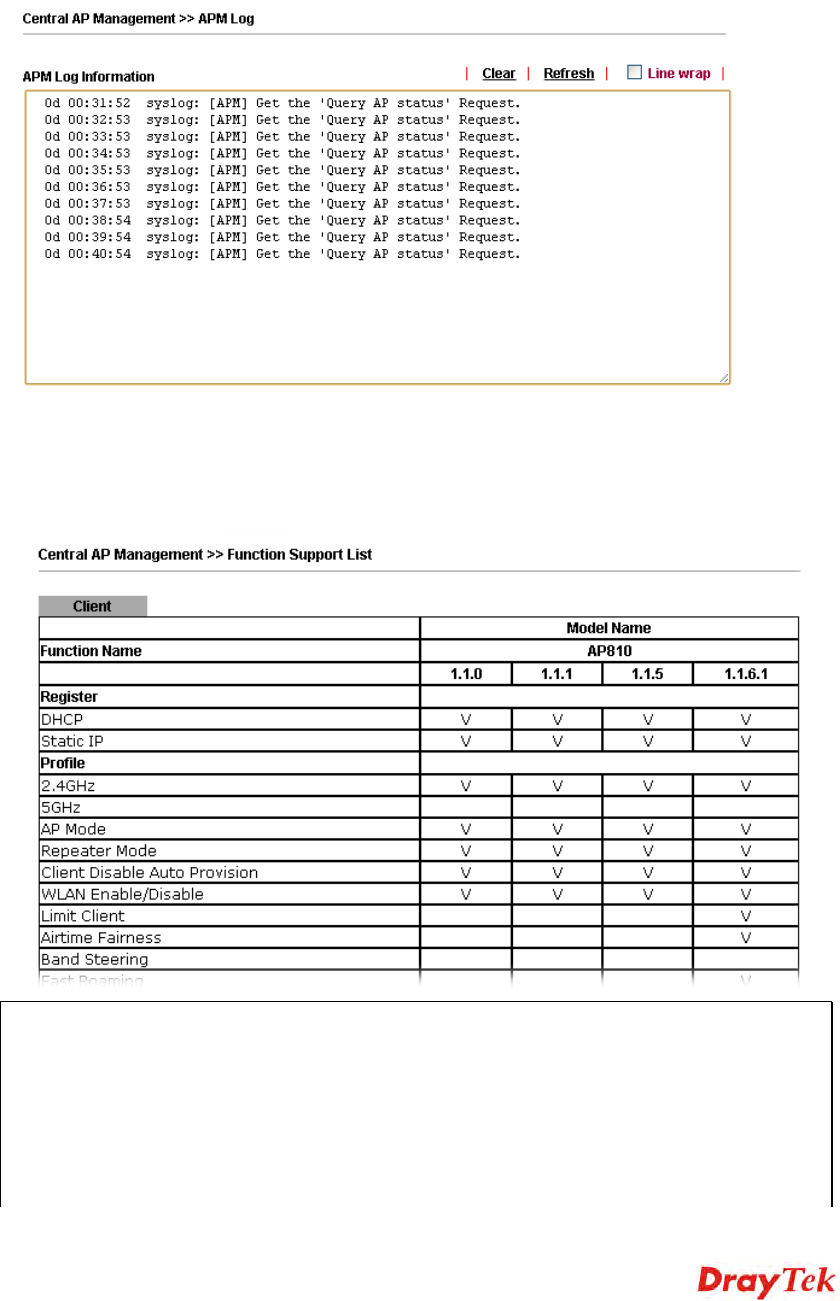
This page will display log information related to wireless stations connected to VigorAP and
central AP management.
Such information also will be delivered to Vigor router (e.g., Vigor2860 or Vigor2925 series)
and be shown on Central AP Management>>APM Log of Vigor router.
3
3.
.3
3.
.3
3
F
Fu
un
nc
ct
ti
io
on
n
S
Su
up
pp
po
or
rt
t
L
Li
is
st
t
Click the Client tab to list the AP management functions that the Access Points support
under different firmware versions.
Note: DrayTek central wireless management (AP Management) lets control, efficiency,
monitoring and security of your company-wide wireless access easier be managed. Inside
the web user interface, we call “central wireless management” as Central AP Management
which supports mobility, client monitoring/reporting and load-balancing to multiple APs.
For central wireless management, you will need a Vigor2860 or Vigor2925 series router;
there is no per-node licensing or subscription required. With the unified user interface of
Vigor2860 Combo WAN series and Vigor2925 Triple WAN series, the multiple
deployment of VigorAP can be clear at the first sight. For multiple wireless clients, to

VigorAP 810 User’s Guide
39
3
3.
.4
4
G
Ge
en
ne
er
ra
al
l
C
Co
on
nc
ce
ep
pt
ts
s
f
fo
or
r
W
Wi
ir
re
el
le
es
ss
s
L
LA
AN
N
The VigorAP 810 is equipped with a wireless LAN interface compliant with the standard
IEEE 802.11n draft 2 protocol. To boost its performance further, the VigorAP 810 is also
loaded with advanced wireless technology to lift up data rate up to 300 Mbps*. Hence, you
can finally smoothly enjoy stream music and video.
Note: * The actual data throughput will vary according to the network conditions and
environmental factors, including volume of network traffic, network overhead and
building materials.
In an Infrastructure Mode of wireless network, VigorAP 810 plays a role as an Access Point
(AP) connecting to lots of wireless clients or Stations (STA). All the STAs will share the
same Internet connection via VigorAP 810. The General Setup will set up the information
of this wireless network, including its SSID as identification, located channel etc.
S
Se
ec
cu
ur
ri
it
ty
y
O
Ov
ve
er
rv
vi
ie
ew
w
WEP (Wired Equivalent Privacy) is a legacy method to encrypt each frame transmitted via
radio using either a 64-bit or 128-bit key. Usually access point will preset a set of four keys
and it will communicate with each station using only one out of the four keys.
WPA (Wi-Fi Protected Access), the most dominating security mechanism in industry, is
separated into two categories: WPA-personal or called WPA Pre-Share Key (WPA/PSK),
and WPA-Enterprise or called WPA/802.1x.
In WPA-Personal, a pre-defined key is used for encryption during data transmission. WPA
applies Temporal Key Integrity Protocol (TKIP) for data encryption while WPA2 applies
AES. The WPA-Enterprise combines not only encryption but also authentication.
Since WEP has been proved vulnerable, you may consider using WPA for the most secure
connection. You should select the appropriate security mechanism according to your needs.
No matter which security suite you select, they all will enhance the over-the-air data
protection and /or privacy on your wireless network. The VigorAP 810 is very flexible and
can support multiple secure connections with both WEP and WPA at the same time.
W
WP
PS
S
I
In
nt
tr
ro
od
du
uc
ct
ti
io
on
n
WPS (Wi-Fi Protected Setup) provides easy procedure to make network connection
between wireless station and wireless access point (VigorAP 810) with the encryption of
WPA and WPA2.
It is the simplest way to build connection between wireless network clients and VigorAP 810.
Users do not need to select any encryption mode and type any long encryption passphrase to
setup a wireless client every time. He/she only needs to press a button on wireless client, and
WPS will connect for client and VigorAP 810 automatically.

VigorAP 810 User’s Guide
41
3
3.
.5
5
W
Wi
ir
re
el
le
es
ss
s
L
LA
AN
N
S
Se
et
tt
ti
in
ng
gs
s
f
fo
or
r
A
AP
P
M
Mo
od
de
e
When you choose AP as the operation mode, the Wireless LAN menu items will include
General Setup, Security, Access Control, WPS, Advanced Setting, AP Discovery, WMM
Configuration, Bandwidth Management, Airtime Fairness, Station Control, Roaming, and
Station List.
Note: The Wireless LAN settings will be changed according to the Operation Mode
selected in section 3.1.

VigorAP 810 User’s Guide
43
Channel Means the channel of frequency of the wireless LAN. You may
switch channel if the selected channel is under serious
interference. If you have no idea of choosing the frequency,
please select AutoSelect to let system determine for you.
Extension Channel With 802.11n, there is one option to double the bandwidth per
channel. The available extension channel options will be varied
according to the Channel selected above. Configure the
extension channel you want.
Enable 2 Subnet
(Simulate 2 APs) Check the box to enable the function for two independent
subnets. Once you enable this function, LAN-A and LAN-B
would be independent. Next, you can connect one router in
LAN-A, and another router in LAN-B. Such mechanism can
make you feeling that you have two independent AP/subnet
functions in one VigorAP 810.
If you disable this function, LAN-A and LAN-B ports are in
the same domain. You could only connect one router (no
matter connecting to LAN-A or LAN-B) in this environment.
Enable SSID #1 is enabled in default. SSID #2 ~ #4 can be enabled
manually.
Hide SSID Check it to prevent from wireless sniffing and make it harder
for unauthorized clients or STAs to join your wireless LAN.
Depending on the wireless utility, the user may only see the
information except SSID or just cannot see any thing about
VigorAP 810 while site surveying. The system allows you to
set three sets of SSID for different usage.
SSID Set a name for VigorAP 810 to be identified. Default settings
are DrayTek-LAN-A and DrayTek-LAN-B. When Enable 2
Subnet is enabled, you can specify subnet interface (LAN-A
or LAN-B) for each SSID by using the drop down menu.
Subnet Choose LAN-A or LAN-B for each SSID. If you choose
LAN-A, the wireless clients connecting to this SSID could
only communicate with LAN-A.
Isolate Member Check this box to make the wireless clients (stations) with the
same SSID not accessing for each other.
VLAN ID Type the value for such SSID. Packets transferred from such
SSID to LAN will be tagged with the number.
If your network uses VLANs, you can assign the SSID to a
VLAN on your network. Client devices that associate using the
SSID are grouped into this VLAN. The VLAN ID range is
from 3 to 4095. The VLAN ID is 0 by default, it means
disabling the VLAN function for the SSID.
After finishing this web page configuration, please click OK to save the settings.

VigorAP 810 User’s Guide 44
3
3.
.5
5.
.2
2
S
Se
ec
cu
ur
ri
it
ty
y
This page allows you to set security with different modes for SSID 1, 2, 3 and 4 respectively.
After configuring the correct settings, please click OK to save and invoke it.
By clicking the Security Settings, a new web page will appear so that you could configure
the settings.
Available settings are explained as follows:
Item Description
Mode There are several modes provided for you to choose.
Disable - The encryption mechanism is turned off.
WEP - Accepts only WEP clients and the encryption key
should be entered in WEP Key.
WPA/PSK or WPA2/PSK or Mixed (WPA+WPA2)/PSK -
Accepts only WPA clients and the encryption key should be
entered in PSK. The WPA encrypts each frame transmitted
from the radio using the key, which either PSK (Pre-Shared
Key) entered manually in this field below or automatically
negotiated via 802.1x authentication.

VigorAP 810 User’s Guide
47
3
3.
.5
5.
.3
3
A
Ac
cc
ce
es
ss
s
C
Co
on
nt
tr
ro
ol
l
For additional security of wireless access, the Access Control facility allows you to restrict
the network access right by controlling the wireless LAN MAC address of client. Only the
valid MAC address that has been configured can access the wireless LAN interface. By
clicking the Access Control, a new web page will appear, as depicted below, so that you
could edit the clients' MAC addresses to control their access rights (deny or allow).
Available settings are explained as follows:
Item Description
Policy Select to enable any one of the following policy or disable the
policy. Choose Activate MAC address filter to type in the
MAC addresses for other clients in the network manually.
Choose Blocked MAC address filter, so that all of the devices
with the MAC addresses listed on the MAC Address Filter
table will be blocked and cannot access into VigorAP 810.
MAC Address Filter Display all MAC addresses that are edited before.
Client’s MAC
Address Manually enter the MAC address of wireless client.
Add Add a new MAC address into the list.
Delete Delete the selected MAC address in the list.
Edit Edit the selected MAC address in the list.
Cancel Give up the access control set up.

VigorAP 810 User’s Guide 48
Backup Click it to store the settings (MAC addresses on MAC Address
Filter table) on this page as a file.
Restore Click it to restore the settings (MAC addresses on MAC
Address Filter table) from an existed file.
After finishing this web page configuration, please click OK to save the settings.
3
3.
.5
5.
.4
4
W
WP
PS
S
Open Wireless LAN>>WPS to configure the corresponding settings.
Available settings are explained as follows:
Item Description
Enable WPS Check this box to enable WPS setting.
WPS Configured Display related system information for WPS. If the wireless
security (encryption) function of VigorAP 810 is properly
configured, you can see ‘Yes’ message here.
WPS SSID Display current selected SSID.
WPS Auth Mode Display current authentication mode of the VigorAP 810. Only
WPA2/PSK and WPA/PSK support WPS.
WPS Encrypt Type Display encryption mode (None, WEP, TKIP, AES, etc.) of
VigorAP 810.
Configure via Push
Button Click Start PBC to invoke Push-Button style WPS setup
procedure. VigorAP 810 will wait for WPS requests from
wireless clients about two minutes. The WPS LED on
VigorAP 810 will blink fast when WPS is in progress. It will
return to normal condition after two minutes. (You need to
setup WPS within two minutes)
Configure via Client
PinCode Type the PIN code specified in wireless client you wish to
connect, and click Start PIN button. The WLAN LED on
VigorAP 810 will blink fast when WPS is in progress. It will
return to normal condition after two minutes. (You need to
VigorAP 810 User’s Guide 50
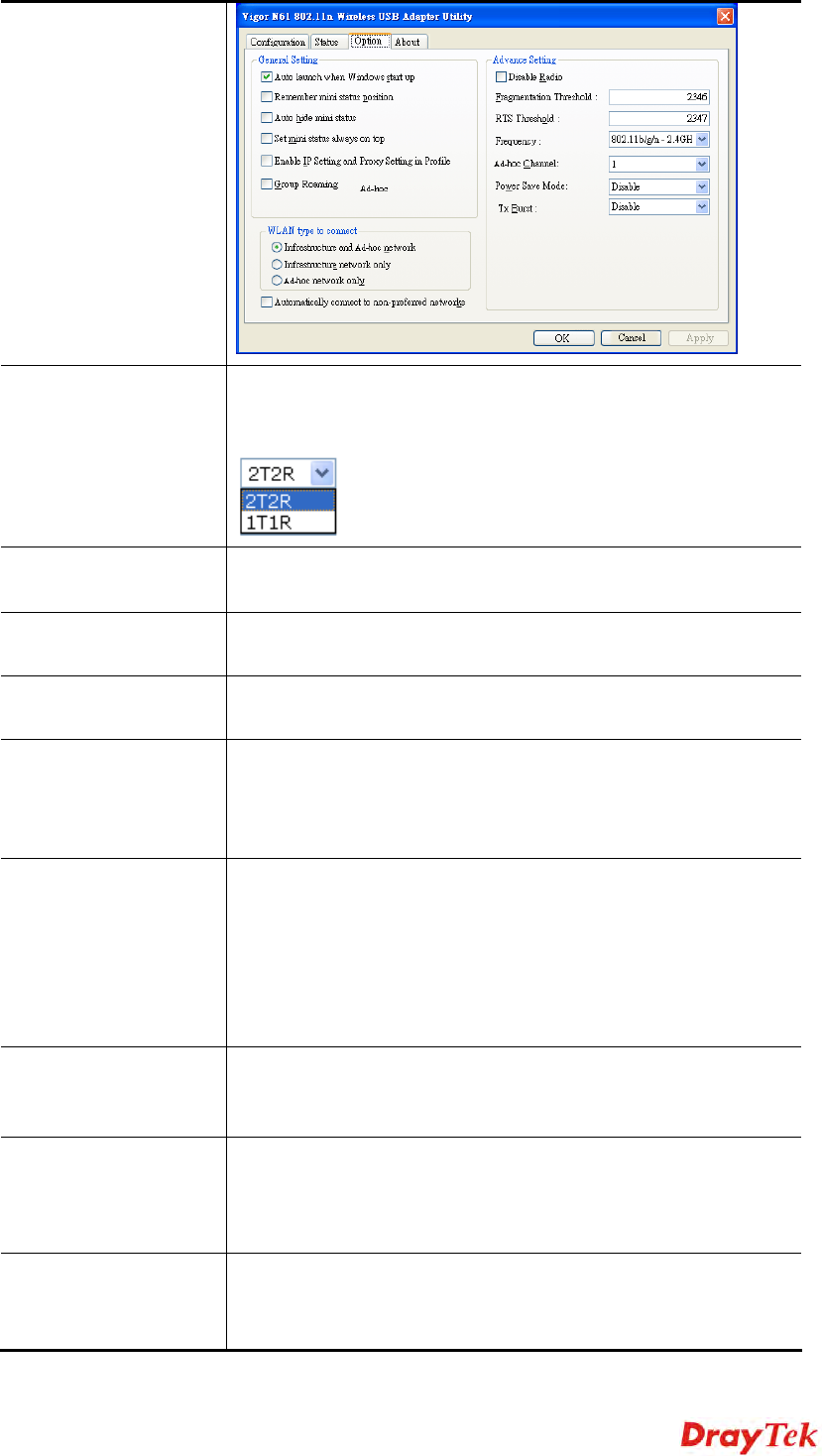
Antenna VigorAP can be attached with two antennas to have good data
transmission via wireless connection. However, if you have
only one antenna attached, please choose 1T1R.
Tx Power The default setting is the maximum (100%). Lowering down
the value may degrade range and throughput of wireless.
Rate Adaptation
Algorithm Wireless transmission rate is adapted dynamically. Usually,
performance of “new” algorithm is better than “old”.
Fragment Length Set the Fragment threshold of wireless radio. Do not modify
default value if you don’t know what it is, default value is
2346.
RTS Threshold Minimize the collision (unit is bytes) between hidden stations
to improve wireless performance.
Set the RTS threshold of wireless radio. Do not modify default
value if you don’t know what it is, default value is 2347.
Country Code VigorAP broadcasts country codes by following the 802.11d
standard. However, some wireless stations will detect / scan
the country code to prevent conflict occurred. If conflict is
detected, wireless station will be warned and is unable to make
network connection. Therefore, changing the country code to
ensure successful network connection will be necessary for
some clients.
Auto Channel
Filtered Out List The selected wireless channels will be discarded if AutoSelect
is selected as Channel selection mode in Wireless
LAN>>General Setup.
IGMP Snooping Check Enable to enable IGMP Snooping. Multicast traffic will
be forwarded to ports that have members of that group.
Disabling IGMP snooping will make multicast traffic treated in
the same manner as broadcast traffic.
Isolate members with
IP The default setting is “Disable”.
If it is enabled, VigorAP will isolate different wireless clients
according to their IP address(es).
VigorAP 810 User’s Guide 52
Encryption Display the encryption mode for the scanned AP.
Authentication Display the authentication type that the scanned AP applied.
Mode Display the wireless connection mode that the scanned AP
used.
Ch. Width Display the channel width that the scanned AP used.
Scan It is used to discover all the connected AP. The results will be
shown on the box above this button
Channel Statistics It displays the statistics for the channels used by APs.
3
3.
.5
5.
.7
7
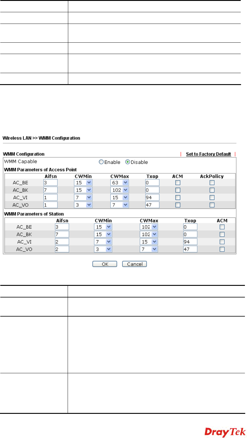
W
WM
MM
M
C
Co
on
nf
fi
ig
gu
ur
ra
at
ti
io
on
n
WMM is an abbreviation of Wi-Fi Multimedia. It defines the priority levels for four access
categories derived from 802.1d (prioritization tabs). The categories are designed with
specific types of traffic, voice, video, best effort and low priority data. There are four
accessing categories - AC_BE , AC_BK, AC_VI and AC_VO for WMM.
Available settings are explained as follows:
Item Description
WMM Capable To apply WMM parameters for wireless data transmission,
please click the Enable radio button.
Aifsn It controls how long the client waits for each data transmission.
Please specify the value ranging from 1 to 15. Such parameter
will influence the time delay for WMM accessing categories.
For the service of voice or video image, please set small value
for AC_VI and AC_VO categories For the service of e-mail or
web browsing, please set large value for AC_BE and AC_BK
categories.
CWMin/CWMax CWMin means contention Window-Min and CWMax means
contention Window-Max. Please specify the value ranging from
1 to 15. Be aware that CWMax value must be greater than
CWMin or equals to CWMin value. Both values will influence
the time delay for WMM accessing categories. The difference
VigorAP 810 User’s Guide
55
3
3.
.5
5.
.9
9
A
Ai
ir
rt
ti
im
me
e
F
Fa
ai
ir
rn
ne
es
ss
s
Airtime fairness is essential in wireless networks that must support critical enterprise
applications.
Most of the applications are either symmetric or require more downlink than uplink capacity;
telephony and email send the same amount of data in each direction, while video streaming
and web surfing involve more traffic sent from access points to clients than the other way
around. This is essential for ensuring predictable performance and quality-of-service, as well
as allowing 802.11n and legacy clients to coexist on the same network. Without airtime
fairness, offices using mixed mode networks risk having legacy clients slow down the entire
network or letting the fastest client(s) crowd out other users.
With airtime fairness, every client at a given quality-of-service level has equal access to the
network's airtime.
The wireless channel can be accessed by only one wireless station at the same time.
The principle behind the IEEE802.11 channel access mechanisms is that each station has
equal probability to access the channel. When wireless stations have similar data rate, this
principle leads to a fair result. In this case, stations get similar channel access time which is
called airtime.
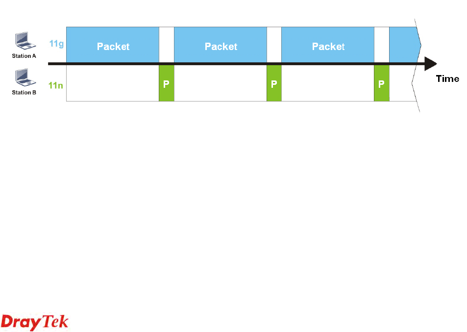
However, when stations have various data rate (e.g., 11g, 11n), the result is not fair. The
slow stations (11g) work in their slow data rate and occupy too much airtime, whereas the
fast stations (11n) become much slower.
Take the following figure as an example, both Station A(11g) and Station B(11n) transmit
data packets through VigorAP 810. Although they have equal probability to access the
wireless channel, Station B(11n) gets only a little airtime and waits too much because Station
A(11g) spends longer time to send one packet. In other words, Station B(fast rate) is
obstructed by Station A(slow rate).
To improve this problem, Airtime Fairness is added for VigorAP 810. Airtime Fairness
function tries to assign similar airtime to each station (A/B) by controlling TX traffic. In the
following figure, Station B(11n) has higher probability to send data packets than Station
A(11g). By this way, Station B(fast rate) gets fair airtime and it's speed is not limited by
Station A(slow rate).

VigorAP 810 User’s Guide 56
It is similar to automatic Bandwidth Limit. The dynamic bandwidth limit of each station
depends on instant active station number and airtime assignment. Please note that Airtime
Fairness of 2.4GHz and 5GHz are independent. But stations of different SSIDs function
together, because they all use the same wireless channel. IN SPECIFIC ENVIRONMENTS,
this function can reduce the bad influence of slow wireless devices and improve the overall
wireless performance.
Suitable environment:
(1) Many wireless stations.
(2) All stations mainly use download traffic.
(3) The performance bottleneck is wireless connection.
Available settings are explained as follows:
Item Description
Enable Airtime
Fairness Try to assign similar airtime to each wireless station by
controlling TX traffic.
Airtime Fairness – Click the link to display the following
screen of airtime fairness note.
Triggering Client Number –Airtime Fairness function is
applied only when active station number achieves this number.
After finishing this web page configuration, please click OK to save the settings.

VigorAP 810 User’s Guide 58
After finishing all the settings here, please click OK to save the configuration.
3
3.
.5
5.
.1
11
1
R
Ro
oa
am
mi
in
ng
g
The network signal for a single wireless access point might be limited by its coverage range.
Therefore, if you want to expand the wireless network in a large exhibition with a quick
method, you can install multiple access points with enabling the Roaming feature for each
AP to reach the purpose of expanding wireless signals seamlessly.
These access points connecting for each other shall be verified by pre-authentication. This
page allows you to enable the roaming feature and the pre-authentication.
Available settings are explained as follows:
Item Description
AP-assisted Client
Roaming Parameters When the link rate of wireless station is too low or the signal
received by the wireless station is too worse, VigorAP 810 will
automatically detect (based on the link rate and RSSI
requirement) and cut off the network connection for that wireless
station to assist it to connect another Wireless AP to get better
signal.
Minimum Basic Rate – Check the box to use the drop down list
to specify a basic rate (Mbps). When the link rate of the wireless
station is below such value, VigorAP 810 will terminate the
network connection for that wireless station.
Disable RSSI Requirement - If it is selected, VigorAP will not
terminate the network connection based on RSSI.
Strictly Minimum RSSI - VigorAP uses RSSI (received signal
strength indicator) to decide to terminate the network connection
of wireless station. When the signal strength is below the value
(dBm) set here, VigorAP 810 will terminate the network
connection for that wireless station.
Minimum RSSI - When the signal strength of the wireless
station is below the value (dBm) set here and adjacent AP (must
be DrayTek AP and support such feature too) with higher signal
strength value (defined in the field of With Adjacent AP RSSI
Termékspecifikációk
| Márka: | Draytek |
| Kategória: | Wifi |
| Modell: | Vigor AP 810 |
Szüksége van segítségre?
Ha segítségre van szüksége Draytek Vigor AP 810, tegyen fel kérdést alább, és más felhasználók válaszolnak Önnek
Útmutatók Wifi Draytek

23 Szeptember 2024
16 Július 2024
15 Július 2024
11 Július 2024
Útmutatók Wifi
- Wifi HP
- Wifi Siemens
- Wifi TRENDnet
- Wifi AVM
- Wifi Strong
- Wifi Netgear
- Wifi Huawei
- Wifi ZyXEL
- Wifi Devolo
- Wifi Tenda
- Wifi Gembird
- Wifi Google
- Wifi Edimax
- Wifi D-Link
- Wifi Iiyama
- Wifi Sitecom
- Wifi Belkin
- Wifi Ziggo
- Wifi Eminent
- Wifi KlikaanKlikuit
- Wifi Easypix
- Wifi Maginon
- Wifi Envivo
- Wifi ICIDU
- Wifi Ubiquiti
- Wifi Telenet
- Wifi Grixx
- Wifi Fantec
- Wifi Verizon
- Wifi T-Mobile
- Wifi Premier
- Wifi Sungevity
- Wifi Mercku
- Wifi Ubee
- Wifi Lab 31
- Wifi SolarNRG
- Wifi Dartwood
- Wifi Ryoko
- Wifi On Networks
- Wifi PENTAGRAM
- Wifi Telfort
- Wifi DKT
Legújabb útmutatók Wifi
16 Január 2025

15 Január 2025
13 Január 2025
12 Január 2025
22 Szeptember 2024
11 Szeptember 2024
11 Szeptember 2024
11 Szeptember 2024
24 Augusztus 2024
24 Augusztus 2024