Használati útmutató Cisco WRP500
Olvassa el alább 📖 a magyar nyelvű használati útmutatót Cisco WRP500 (154 oldal) a router kategóriában. Ezt az útmutatót 10 ember találta hasznosnak és 2 felhasználó értékelte átlagosan 4.5 csillagra
Oldal 1/154

Cisco Systems, Inc.
www.cisco.com
Cisco has more than 200 offices worldwide.
Addresses, phone numbers, and fax numbers
are listed on the Cisco website at
www.cisco.com/go/offices.
Cisco WRP500 Administration Guide
Wireless-AC Broadband Router with 2 Phone Ports and Built-In Analog
Telephone Adapter
Published: January 30, 2015
Revised: April 29, 2015
ADMINISTRATION GUIDE

THE SPECIFICATIONS AND INFORMATION REGARDING THE PRODUCTS IN THIS MANUAL ARE SUBJECT TO CHANGE WITHOUT NOTICE. ALL
STATEMENTS, INFORMATION, AND RECOMMENDATIONS IN THIS MANUAL ARE BELIEVED TO BE ACCURATE BUT ARE PRESENTED WITHOUT
WARRANTY OF ANY KIND, EXPRESS OR IMPLIED. USERS MUST TAKE FULL RESPONSIBILITY FOR THEIR APPLICATION OF ANY PRODUCTS.
THE SOFTWARE LICENSE AND LIMITED WARRANTY FOR THE ACCOMPANYING PRODUCT ARE SET FORTH IN THE INFORMATION PACKET THAT
SHIPPED WITH THE PRODUCT AND ARE INCORPORATED HEREIN BY THIS REFERENCE. IF YOU ARE UNABLE TO LOCATE THE SOFTWARE LICENSE
OR LIMITED WARRANTY, CONTACT YOUR CISCO REPRESENTATIVE FOR A COPY.
The following information is for FCC compliance of Class A devices: This equipment has been tested and found to comply with the limits for a Class A digital device, pursuant
to part 15 of the FCC rules. These limits are designed to provide reasonable protection against harmful interference when the equipment is operated in a commercial
environment. This equipment generates, uses, and can radiate radio-frequency energy and, if not installed and used in accordance with the instruction manual, may cause
harmful interference to radio communications. Operation of this equipment in a residential area is likely to cause harmful interference, in which case users will be required
to correct the interference at their own expense.
The following information is for FCC compliance of Class B devices: This equipment has been tested and found to comply with the limits for a Class B digital device, pursuant
to part 15 of the FCC rules. These limits are designed to provide reasonable protection against harmful interference in a residential installation. This equipment generates,
uses and can radiate radio frequency energy and, if not installed and used in accordance with the instructions, may cause harmful interference to radio communications.
However, there is no guarantee that interference will not occur in a particular installation. If the equipment causes interference to radio or television reception, which can be
determined by turning the equipment off and on, users are encouraged to try to correct the interference by using one or more of the following measures:
• Reorient or relocate the receiving antenna.
• Increase the separation between the equipment and receiver.
• Connect the equipment into an outlet on a circuit different from that to which the receiver is connected.
• Consult the dealer or an experienced radio/TV technician for help.
Modifications to this product not authorized by Cisco could void the FCC approval and negate your authority to operate the product.
The Cisco implementation of TCP header compression is an adaptation of a program developed by the University of California, Berkeley (UCB) as part of UCB’s public
domain version of the UNIX operating system. All rights reserved. Copyright © 1981, Regents of the University of California.
NOTWITHSTANDING ANY OTHER WARRANTY HEREIN, ALL DOCUMENT FILES AND SOFTWARE OF THESE SUPPLIERS ARE PROVIDED “AS IS” WITH
ALL FAULTS. CISCO AND THE ABOVE-NAMED SUPPLIERS DISCLAIM ALL WARRANTIES, EXPRESSED OR IMPLIED, INCLUDING, WITHOUT
LIMITATION, THOSE OF MERCHANTABILITY, FITNESS FOR A PARTICULAR PURPOSE AND NONINFRINGEMENT OR ARISING FROM A COURSE OF
DEALING, USAGE, OR TRADE PRACTICE.
IN NO EVENT SHALL CISCO OR ITS SUPPLIERS BE LIABLE FOR ANY INDIRECT, SPECIAL, CONSEQUENTIAL, OR INCIDENTAL DAMAGES, INCLUDING,
WITHOUT LIMITATION, LOST PROFITS OR LOSS OR DAMAGE TO DATA ARISING OUT OF THE USE OR INABILITY TO USE THIS MANUAL, EVEN IF CISCO
OR ITS SUPPLIERS HAVE BEEN ADVISED OF THE POSSIBILITY OF SUCH DAMAGES.
Cisco and the Cisco logo are trademarks or registered trademarks of Cisco and/or its affiliates in the U.S. and other countries. To view a list of Cisco trademarks, go to this
URL: www.cisco.com/go/trademarks. Third-party trademarks mentioned are the property of their respective owners. The use of the word partner does not imply a partnership
relationship between Cisco and any other company. (1110R)
Any Internet Protocol (IP) addresses and phone numbers used in this document are not intended to be actual addresses and phone numbers. Any examples, command display
output, network topology diagrams, and other figures included in the document are shown for illustrative purposes only. Any use of actual IP addresses or phone numbers in
illustrative content is unintentional and coincidental.
© 2015 Cisco Systems, Inc. All rights reserved.

iii
Cisco WRP500 Administration Guide
C O N T E N T S
C H A P T E R
1Product Overview and Deployment Guidelines 1-1
WRP500 Features and Benefits 1-1
Deployment Models 1-2
WRP500 Deployment in a Basic Network 1-3
WRP500 Deployment with a Wireless Guest Network 1-4
WRP500 Deployment with Mobile Broadband 1-5
Mobile Office That Uses the Mobile Network for Internet Access 1-5
Basic Office Deployment That Uses the Mobile Network as a Backup Connection 1-6
Local Area Network Guidelines 1-6
Power, Cabling, and Telephone Lines 1-6
Basic Services and Equipment 1-7
Special Requirements for Voice Deployments 1-7
Bandwidth for Voice Deployments 1-7
NAT Mapping for Voice over IP Deployments 1-8
Local Area Network Design for Voice Deployments 1-9
WRP500 Maintenance Operations 1-9
Remote Provisioning 1-10
Upgrade URL 1-10
Resync URL 1-11
Reboot URL 1-11
Configuration Profile 1-12
XML Format 1-12
Binary Format 1-12
C H A P T E R
2Configure Your System for ITSP Interoperability 2-1
Configure NAT Mapping 2-1
Configure NAT Mapping with a Static IP Address 2-1
Configure NAT Mapping with STUN 2-2
Determine Whether the Router Uses Symmetric or Asymmetric NAT 2-4
Firewalls and SIP 2-5
Configure SIP Timer Values 2-5

Contents
iv
Cisco WRP500 Administration Guide
C H A P T E R
3Configure Voice Services 3-1
Analog Telephone Adapter Operations 3-1
ATA Software Features 3-2
Supported Codecs 3-2
SIP Proxy Redundancy 3-2
Other ATA Software Features 3-3
Register to the Service Provider 3-5
Manage Caller ID Service 3-7
Optimize Fax Completion Rates 3-8
Fax Troubleshooting 3-9
Silence Suppression and Comfort Noise Generation 3-10
Configure Dial Plans 3-10
About Dial Plans 3-10
Digit Sequences 3-11
Digit Sequence Examples 3-12
Acceptance and Transmission of Dialed Digits 3-13
Dial Plan Timer (Off-Hook Timer) 3-14
Interdigit Long Timer (Incomplete Entry Timer) 3-15
Interdigit Short Timer (Complete Entry Timer) 3-15
Edit Dial Plans 3-16
Enter the Line Interface Dial Plan 3-16
Reset the Control Timers 3-16
Secure Call Implementation 3-17
Enable Secure Calls 3-17
A P P E N D I X
AAdvanced Voice Fields A-1
Info page A-1
Product Information section A-1
System Status section A-2
Line Status section A-2
System page A-4
System Configuration section A-4
Miscellaneous Settings section A-5
SIP page A-5
SIP Parameters section A-5
SIP Timer Values (sec) section A-7
Response Status Code Handling section A-8
RTP Parameters section A-8

Contents
v
Cisco WRP500 Administration Guide
SDP Payload Types section A-9
NAT Support Parameters section A-10
Regional page A-11
Call Progress Tones section A-12
Distinctive Ring Patterns section A-13
Distinctive Call Waiting Tone Patterns section A-14
Distinctive Ring/CWT Pattern Names section A-15
Control Timer Values (sec) section A-16
Vertical Service Activation Codes section A-17
Outbound Call Codec Selection Codes section A-22
Miscellaneous section A-23
Line page A-24
Line Enable section A-25
Streaming Audio Server (SAS) section A-25
NAT Settings section A-26
Network Settings section A-27
SIP Settings section A-28
Call Feature Settings section A-30
Proxy and Registration section A-31
Subscriber Information section A-32
Supplementary Service Subscription section A-32
Audio Configuration section A-34
Dial Plan section A-36
FXS Port Polarity Configuration section A-38
User page A-38
Call Forward Settings section A-38
Selective Call Forward Settings section A-39
Speed Dial Settings section A-39
Supplementary Service Settings section A-40
Distinctive Ring Settings section A-41
Ring Settings section A-41
A P P E N D I X
BData Fields B-1
Interface Setup module B-1
Interface Setup > WAN page B-1
Interface Setup > WAN > Internet Setup B-1
Interface Setup > WAN > Internet Option B-3
Internet Setup > WAN > Mobile Network B-4
Internet Setup > WAN > Multi-WAN Config B-6

Contents
vi
Cisco WRP500 Administration Guide
Interface Setup > LAN page B-7
Interface Setup > LAN > DHCP Server B-7
Interface Setup > LAN > VLAN Settings B-9
Interface Setup > LAN > Port Settings B-11
Interface Setup > LAN > STP B-12
Interface Setup > Wi-Fi Settings B-13
Interface Setup > Wi-Fi Settings > Basic Wireless Settings B-13
Interface Setup > Wi-Fi Settings > Wi-Fi Protected Setup B-14
Interface Setup > Wi-Fi Settings > Advanced Wireless Settings B-15
Interface Setup > Wi-Fi Settings > WMM Setting B-16
Interface Setup > Management Interface B-16
Network Setup module B-16
Network Setup > Routing page B-17
Network Setup > Routing > Static Routes > IPv4 B-17
Network Setup > Routing > RIP > IPv4 B-18
Network Setup > Routing > Intervlan Routing B-19
Network Setup > Routing > Policy Routing B-19
Network Setup > NAT B-20
Network Setup > NAT > NAT Setting B-20
Network Setup > NAT > NAT Bypass B-20
Network Setup > NAT > Port Forwarding B-22
Network Setup > NAT > Port Range Triggering B-24
Network Setup > QoS B-25
Network Setup > QoS > QoS Bandwidth Control B-25
Network Setup > QoS > QoS Policy B-25
Network Setup > QoS > CoS To Queue B-29
Network Setup > QoS > DSCP To Queue B-29
Network Setup > Firewall B-29
Network Setup > Firewall > Firewall Filter B-29
Network Setup > Firewall > Firewall Filter B-30
Network Setup > Firewall > IPV4 > Internet Access Control B-30
Network Setup > Firewall > IPV4 > Inbound Access Control B-32
Network Setup > PPPoE Relay B-34
Network Setup > DDNS B-34
Network Setup > DMZ B-35
Network Setup > DMZ > Software DMZ B-35
Network Setup > DMZ > Hardware DMZ B-36
Network Setup > IGMP B-36
Network Setup > UPnP B-36
Network Setup > CDP B-37

Contents
vii
Cisco WRP500 Administration Guide
Network Setup > DNS Spoofing B-37
VPN module B-38
VPN > Site to Site IPSec VPN B-38
VPN > Site to Site IPSec VPN > NAT Traversal B-38
VPN > Site to Site IPSec VPN > IKE Policy B-38
VPN > Site to Site IPSec VPN > IPSec Policy B-39
VPN > GRE Tunnel B-41
VPN > VPN Passthrough B-42
VPN > Cisco VPN Server B-42
VPN > Cisco VPN Server > Group B-42
VPN > Cisco VPN Server > User B-43
Administration module B-44
Administration > Web Access Management B-44
Administration > Remote Support B-45
Administration > Remote Management B-45
Administration > Remote Management > TR-069 B-45
Administration > Remote Management > SNMP B-46
Administration > Remote Management > Local TFTP B-47
Administration > Time Setup B-48
Administration > Certificate Management B-48
Administration > User Management B-49
Administration > User Management > Password Complexity Settings B-49
Administration > User Management > User List B-50
Administration > User Privilege Control B-50
Administration > Log B-50
Administration > Log > Log Setting B-50
Administration > Log > Log Module B-52
Administration > Log > Log Viewer B-52
Administration > Log > Firewall Log B-52
Administration > Factory Defaults B-53
Administration > Firmware Upgrade B-54
Administration > Backup & Restore B-54
Administration > Backup & Restore > Default Configuration B-54
Administration > Backup & Restore > Backup Configuration B-54
Administration > Backup & Restore > Restore Configuration B-55
Administration > Reboot B-55
Administration > Switch Setting B-55
Administration > Switch Setting > Port Status B-55
Administration > Switch Setting > Bind MAC to Port B-55
Administration > Status B-57

Contents
viii
Cisco WRP500 Administration Guide
A P P E N D I X
CTroubleshooting C-1
A P P E N D I X
DEnvironmental Specifications for the WRP500 D-1
A P P E N D I X
EWhere to Go From Here E-1

C H A P T E R
1-1
Cisco WRP500 Administration Guide
1
Product Overview and Deployment Guidelines
This chapter describes the features and benefits of the WRP500, describes deployment scenarios, and
offers guidelines to help you plan your network.
•WRP500 Features and Benefits, page 1-1
•Deployment Models, page 1-2
•Local Area Network Guidelines, page 1-6
•Special Requirements for Voice Deployments, page 1-7
•WRP500 Maintenance Operations, page 1-9
•Remote Provisioning, page 1-10
WRP500 Features and Benefits

1-2
Cisco WRP500 Administration Guide
Chapter 1 Product Overview and Deployment Guidelines
Deployment Models
With a variety of features, the WRP500 offers the benefits of five devices in one:
•Router: The WRP500 is a broadband router with a robust security firewall to protect your network.
•Switch: The WRP500 includes a built-in, 4-port, full-duplex, 10/100/1000M Ethernet switch to
connect computers, printers, and other equipment directly or to attach additional hubs and switches.
Advanced Quality of Service functionality ensures that you can prioritize traffic for data, voice, and
video applications.
•Analog Telephone Adapter: The WRP500 includes a two-port Analog Telephone Adapter (ATA)
that allows you to connect your analog phones or fax machines to your configured Internet telephone
service. Two traditional phone lines also can be connected for support of legacy phone numbers and
fax numbers.
•Wireless Access Point: The WRP500 has an integrated 802.11ac/b/g/n wireless access point that
secures your communications with WEP, WPA, and WPA2 security protocols. It is preconfigured to
support two wireless networks: one for transferring general data, such as data from a connected PC;
and another for transferring data from voice devices, such as audio or fax data.
•Mobile Broadband Router: When you attach a compatible Mobile Broadband Modem to the USB
port, the WRP500 allows multiple Wi-Fi and Ethernet devices to share a mobile broadband
connection. This feature also can be used to provide continuous Internet service by providing
automatic failover to the mobile network when the primary Internet connection is unavailable. For
the latest copy of the USB Modem Compatibility List, visit the following URL:
http://www.cisco.com/c/en/us/products/unified-communications/wrp500-wireless-g-broadband-ro
uter-2-phone-ports/index.html
Note Because this device has many unique functions, the administrative tasks for the WRP500 may be
different from corresponding tasks on other Cisco Small Business routers, switches, and ATAs.
Administrators should refer to this guide for the proper procedures for installation, configuration, and
management of the WRP500.
Deployment Models
The versatility of the WRP500 makes it useful for a variety of deployments:
•WRP500 Deployment in a Basic Network, page 1-3
•WRP500 Deployment with a Wireless Guest Network, page 1-4
•WRP500 Deployment with Mobile Broadband, page 1-5

1-3
Cisco WRP500 Administration Guide
Chapter 1 Product Overview and Deployment Guidelines
Deployment Models
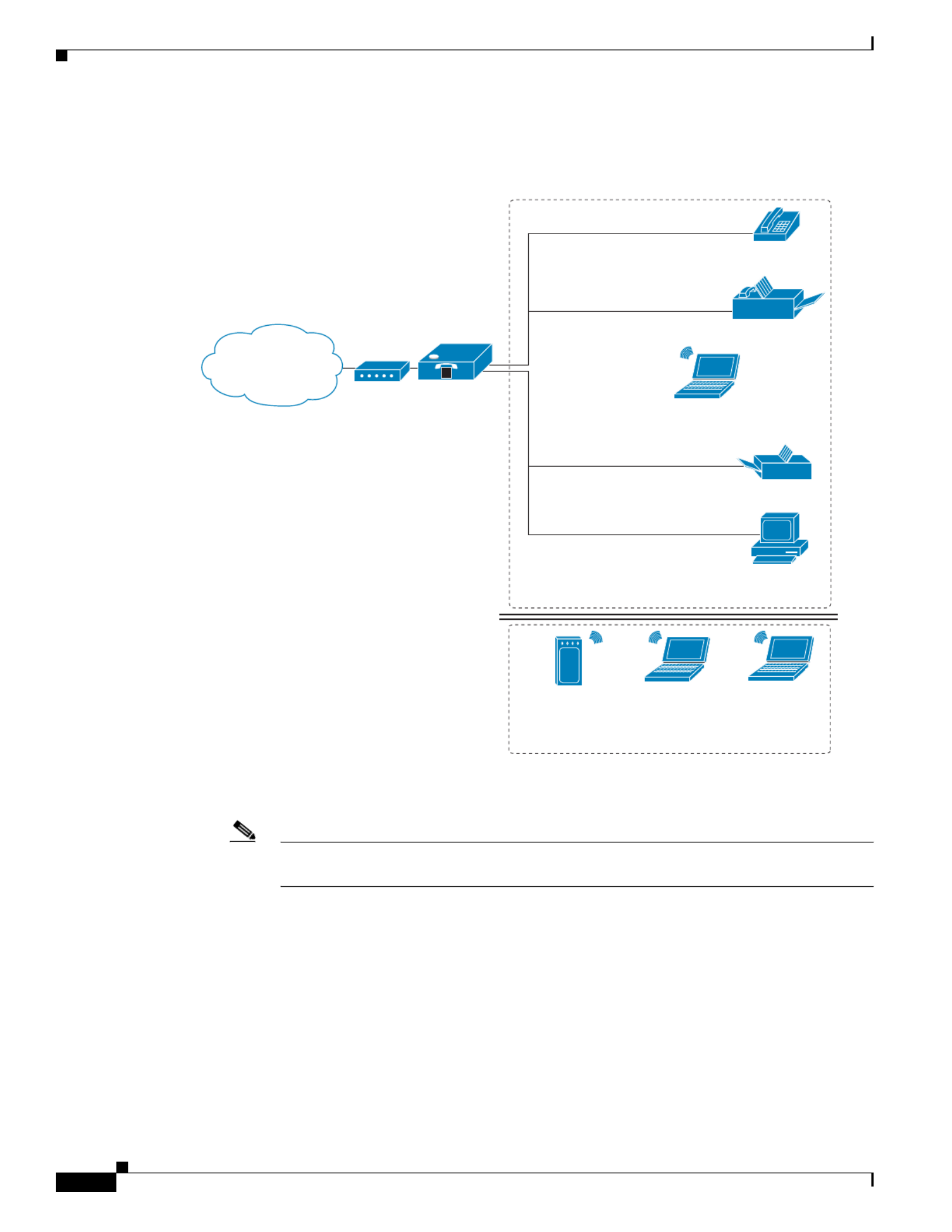
WRP500 Deployment in a Basic Network
In this scenario, the WRP500 is deployed in a small business that has a basic network configuration.
•The WRP500 is preconfigured by the Service Provider to act as the edge device that routes traffic
between the small business network and the Service Provider network.
Note The WRP500 may be configured as an edge device or can be connected to another device
that provides access to the Service Provider network.
•The WRP500 connects computers to the Internet. Computers may be connected by network cables
or may operate wirelessly. All computers have access to the printer on the local network.
•An analog phone and a fax mach phone ports and have access to ine are connected to the WRP500
the configured Voice over IP services.
Personal
Computer
WRP500 Laptop
Computer
Analog Phone
Fax
Printer
Private Network
Internet
384027
V
1-4
Cisco WRP500 Administration Guide
Chapter 1 Product Overview and Deployment Guidelines
Deployment Models
WRP500 Deployment with a Wireless Guest Network
In this example, the WRP500 is deployed in an Internet cafe.
•The WRP500 is connected to a cable modem that provides Internet access.
Note The WRP500 may be configured as an edge device or can be connected to another device
that provides access to the Service Provider network.
•In the private network, a computer is connected to the WRP500 by an Ethernet cable. The manager
also has a laptop computer that can be used wirelessly from anywhere on the premises through the
main wireless network, SSID1. The manager and employees who use SSID1 have access to the
printer. If desired, a wireless phone can also connect to this network for business use.
•An analog phone and a fax machine are in the private network. The WRP500 is configured for
Internet telephone service.
•The WRP500 is configured with a guest network, SSID2, that enables the business to provide its
customers with a free wireless hotspot for their laptop computers and other mobile devices. Because
this network is separate from the main wireless network, customers have no access to the manager’s
computer, printer, or telephone service.
Internet
Access
Device
Wireless Guest Network
Personal
Computer
WRP500
Laptop
Computer
Analog Phone
Fax
Printer
Private Network
Internet
384028
V

1-5
Cisco WRP500 Administration Guide
Chapter 1 Product Overview and Deployment Guidelines
Deployment Models
WRP500 Deployment with Mobile Broadband
When a compatible mobile broadband modem connects to the USB port, the WRP500 can connect to a
mobile broadband network. The mobile network can be the primary network or can serve as a backup
network to ensure continuous Internet connectivity. Consider the scenarios that follow.
Mobile Office That Uses the Mobile Network for Internet Access
In this example, a team has set up a temporary network at a construction site. Team members have laptop
computers and Wi-Fi phones that share a mobile broadband connection for Internet access. All
computers can connect to the printer on the local network. If a Virtual Private Network (VPN) tunnel is
configured on the laptop computer, team members also can securely connect to resources at the main
office (not illustrated).
Laptop
Computer
Printer
Wi-Fi Phone
Mobile Office Network
1
Mobile
Network
384030
*with compatible 3G USB Modem
WRP500*
V

1-6
Cisco WRP500 Administration Guide
Chapter 1 Product Overview and Deployment Guidelines
Local Area Network Guidelines
Basic Office Deployment That Uses the Mobile Network as a Backup Connection
In this example, the business has the same network as illustrated in the “WRP500 Deployment in a Basic
Network” section on page 1-3. However, this business has the added benefit of using the mobile
broadband network as a backup network to ensure continuous Internet connectivity. In the event that the
Internet connection fails, the WRP500 fails over to the configured mobile network. When the Internet
connection becomes available, the WRP500 recovers the connection.
Local Area Network Guidelines
This section offers guidelines for setting up your Local Area Network (LAN).
Note As you design your network, be aware that the WRP500 is intended for deployment in a very small
business. The router is designed to handle the data, voice, and video traffic that is expected by office
personnel who use the Internet to find data, conduct phone conversations, transmit email, and participate
in videoconferences. For large-scale operations with heavy data, voice, and video requirements, consider
other models of Cisco Small Business routers.
Power, Cabling, and Telephone Lines
•AC outlets: Ensure that an AC outlet is available for every network device that requires AC power.
–
The WRP500 requires power, and Ethernet switches (optional) require power.
–
Some analog telephones require AC power.
Personal
Computer
WRP500*
Laptop
Computer
Analog Phone
Fax
Printer
Private Network
Internet
384029
1
Mobile
Network
Failover
V
*with compatible 3G USB Modem

1-7
Cisco WRP500 Administration Guide
Chapter 1 Product Overview and Deployment Guidelines
Special Requirements for Voice Deployments
•Ethernet cabling: If an Internet access device is present, you need to connect it to the WRP500 with
an Ethernet cable. You also need Ethernet cable for any devices that do not have wireless
connectivity. Ethernet cables that are UTP Cat5e or better are recommended.
•UPS: It is strongly recommended that you included an Uninterrupted Power Supply (UPS)
mechanism in your network to ensure continuous operation during a power failure. Connect all
essential devices, including the Internet access device, the WRP500, and the Ethernet switch (if
present).
Basic Services and Equipment
The following basic services and equipment are required:
•An integrated access device or modem for broadband access to the Internet
•Business grade Internet service
•Internet Telephony Service Provider (ITSP) for Voice over IP (VoIP) telephone service that supports
a “bring your own device” model
•A computer with Microsoft Windows for system configuration
Special Requirements for Voice Deployments
Voice deployments have special requirements that you must meet to ensure voice quality.
•Bandwidth for Voice Deployments, page 1-7
•NAT Mapping for Voice over IP Deployments, page 1-8
•Local Area Network Design for Voice Deployments, page 1-9
Bandwidth for Voice Deployments
You can choose from several types of broadband access technologies to provide symmetric or
asymmetric connectivity to a small business. These technologies vary on the available bandwidth and on
the quality of service. For voice deployments, it is generally recommended that you use broadband
access with a Service Level Agreement that provides quality of service. If a Service Level Agreement
with regard to the broadband connection quality of service is not in place, the downstream audio quality
may be affected negatively under heavy load conditions (bandwidth utilization beyond 80%).
To eliminate or minimize this effect, Cisco recommends one of the following actions:
•For broadband connections with a bandwidth lower than 2 Mbps, perform the call capacity
calculations by assuming a bandwidth value of 50% of the existing broadband bandwidth. For
example, in the case of a 2 Mbps uplink broadband connection, assume 1 Mbps. Limit the uplink
bandwidth in the Integrated Access Device to this value. This setting helps to maintain utilization
levels below 60%, and thus reduces jitter and packet loss.
•Use an additional broadband connection for voice services only. A separate connection is required
when the broadband connection services do not offer quality of service and when it is not possible
to apply the above mentioned utilization mechanism.
The available connection bandwidth determines the maximum number of simultaneous calls that the
system can support with the appropriate audio quality. Use this information to determine the maximum
number of simultaneous VoIP connections that the system can support.

1-8
Cisco WRP500 Administration Guide
Chapter 1 Product Overview and Deployment Guidelines
Special Requirements for Voice Deployments
Note Some ITSP SIP trunk services limit the maximum number of simultaneous calls. Please check with your
Service Provider to understand the maximum number of simultaneous calls that each SIP trunk supports.
The following table provides the approximate bandwidth budget for different codecs.
Note The Cisco WRP500 supports only the G.711 and G.729 codecs.
For more information about bandwidth calculation, refer to the following web sites:
www.erlang.com/calculator/lipb/
www.bandcalc.com/
NAT Mapping for Voice over IP Deployments
Network Address Translation (NAT) is the function that allows multiple devices in your small business
network to share one external (public) IP address that you receive from your Internet Service Provider.
Voice over IP can co-exist with NAT only when some form of NAT traversal is provided.
Some Internet Telephone Service Providers (ITSPs) provide NAT traversal, but some do not. For voice
deployments, it is strongly recommended that you choose an ITSP that supports NAT mapping
through a Session Border Controller.
If your ITSP does not provide NAT mapping through a Session Border Controller (the preferred method),
you have these options for providing NAT traversal on your WRP500:
•Deploy an edge device that has a SIP ALG (Application Layer Gateway). The Cisco Small Business
WRV200 is suited for this purpose, but other SIP-ALG routers can be used. If your Internet Service
Provider provides the edge device, check with your provider to determine whether the router has a
SIP ALG.
•Configure NAT mapping with the EXT IP setting. This option requires that you have (1) a static
external (public) IP address from your Internet Service Provider and (2) an edge device with a
symmetric NAT mechanism. If the WRP500 is the edge device, the second requirement is met. For
more information about the EXT IP setting, see the “NAT Support Parameters section” section on
page A-10.
•Configure Simple Traversal of UDP through NAT (STUN). This option requires that you have (1) a
dynamic external (public) IP address from your service provider, (2) a computer that is running
STUN server software, and (3) an edge device with an asymmetric NAT mechanism. If the WRP500
is the edge device, the third requirement is not met. For more information about the STUN Enable
setting and the STUN Test Enable setting, see the “NAT Support Parameters section” section on
page A-10.
Codec
Approximate Bandwidth Budget
for Each Side of Conversation 2 Calls 4 Calls 6 Calls 8 Calls
G.711 128 kbps 256 kbps 512 kbps 768 kbps 1024 kbps
G.729 16 kbps 32 kbps 64 kbps 96 kbps 128 kbps

1-9
Cisco WRP500 Administration Guide
Chapter 1 Product Overview and Deployment Guidelines
WRP500 Maintenance Operations
Local Area Network Design for Voice Deployments
Use these guidelines to manage the LAN setup for voice deployments:
•Ensure that all telephones are located in the same local area network subnet.
•Configure your WRP500 as a DHCP server for the purpose of easily adding network devices to the
system. Ensure that the DHCP server can assign enough IP addresses to serve the devices that you
need to connect to your network.
•Use stable DNS server addresses for URL name resolution. Your Internet Service Provider can
provide the primary and secondary DNS server IP addresses.
•If you need to connect more than four network devices directly (other than wireless devices), you
need to connect an Ethernet switch to the WRP500. For voice deployments, Cisco recommends use
of the SLMxxxP, SRWxxxP and SRWxxxMP switch product families. The SLM224P is a popular
choice. For more information about these switches, visit the following URL:
www.cisco.com/cisco/web/solutions/small_business/products/routers_switches/index.html
•If you use an Ethernet switch, configure it to ensure voice quality. These settings are recommended:
–
Enable Port Fast and Spanning Tree Protocol on the ports to which your voice devices are
connected. Cisco phones are capable of rebooting in a few seconds and will attempt to locate
network services while a switch port is being blocked by STP after it senses a device reboot. If
you enable Port Fast, the network will be available to the phones when it is needed. If the switch
does not provide a way to enable Port Fast, you must disable Spanning Tree Protocol.
–
In the administrative web pages for the switch, enable QoS and choose DSCP as the Trust Mode.
WRP500 Maintenance Operations
Due to its unique functions, the WRP500 has unique maintenance operations as compared to other Cisco
Small Business IP telephony devices.
•Remote Management: For security purposes, remote management is disabled by default.
–
When you first configure the WRP500, connect your administrative computer directly to one of
the LAN ports and enter the default static IP address into your web browser to log on to the
configuration utility.
Note The default LAN IP address of the WRP500 is 192.168.15.1. If another device on the
network has the same IP address, the WRP500 takes the address 192.168.16.1. To
modify the Local IP Address, go to the Interface Setup tab > LAN > DHCP Server
section.
If you are using the IVR, be aware that this address is NOT the address that the 110
option of the IVR reports. The device does not respond to the 110 option address.
–
To enable web access and wireless access to the configuration utility, use the Administration
tab > Web Access Management section.
•DHCP Server: The DCHP server on LAN ports is enabled by default. This setting is on the Interface
Setup tab > LAN > DHCP Server section.
•System Logging: To enable system logging, be aware that two sets of system logs exist: one for the
data (router) functions and another for the voice functions.

1-10
Cisco WRP500 Administration Guide
Chapter 1 Product Overview and Deployment Guidelines
Remote Provisioning
–
Data (router) logging: See the Administration tab > Log page.
–
Voice logging: See the Voice tab > System page, Miscellaneous Settings section.
•Factory Reset: To reset your WRP500 to the factory default settings, reset the data (router) settings
and the voice settings separately.
Factory Reset of Data (Router) Settings
Use one of the following methods:
•Option 1: Log on to the configuration utility, then click Administration > Factory Defaults. Next
to Restore Router Factory Defaults, click Yes. Then click Submit to begin the operation.
•Option 2: Press and hold the reset button located on the rear panel for approximately ten seconds.
Factory Reset of Voice Settings
Use one of the following methods:
•Option 1: Log on to the configuration utility, then click Administration tab > Factory Defaults. Next
to Restore Voice Factory Defaults, click Yes. Then click Submit to begin the operation.
•Option 2: Connect an analog phone to the Phone 1 or Phone 2 port. Press **** to access the
Interactive Voice Response menu. After you hear the greeting, press 73738 for factory reset. Listen
to the prompts, then press 1 to confirm or * to cancel.
Remote Provisioning
Like other Cisco Small Business IP Telephony Devices, the WRP500 provides for secure provisioning
and remote upgrade. Provisioning is achieved through configuration profiles that are transferred to the
device via TFTP, HTTP, or HTTPS. To configure Provisioning, go to the Provisioning tab in the
Configuration Utility.
For complete details, see the Provisioning Guide at the following URL:
http://www.cisco.com/c/dam/en/us/td/docs/voice_ip_comm/csbpvga/ata/provisioning/guide/Provisioni
ng.pdf
Upgrade URL
Remote firmware upgrade is achieved via TFTP or HTTP/HTTPS. Remote upgrades are initiated by
causing the WRP500 to request the upgrade firmware image by providing a URL for the WRP500 to
retrieve the firmware.
Note The Upgrade/Resync/Reboot URL works only after the administrator logs in to the web GUI.
Note If the value of the Upgrade Enable parameter in the Provisioning page is No, you cannot upgrade the
WRP500 even if the web page indicates otherwise.
The syntax of the Upgrade URL is as follows:
http://WRP500_ip_address/admin/upgrade?[protocol://][server-name[:port]][/firmware-pathname]

1-11
Cisco WRP500 Administration Guide
Chapter 1 Product Overview and Deployment Guidelines
Remote Provisioning
HTTP, HTTPS, and TFTP are supported for the upgrade operation.
If no protocol is specified, TFTP is assumed.
If no port specified, the default port of the protocol is used (69 for TFTP, 80 for HTTP, or 443 for
HTTPS).
The firmware-pathname is typically the file name of the binary that is located in a directory on the TFTP,
HTTP, or HTTPS server. If no firmware-pathname is specified, /spa.bin is assumed, as in the following
example:
http://192.168.2.217/amin/upgrade?tftp://192.168.2.251/spa.bin
Resync URL
The WRP500 can be configured to automatically resync its internal configuration state to a remote
profile periodically and on power up. The automatic resyncs are controlled by configuring the desired
profile URL into the device.
Note The Upgrade/Resync/Reboot URL works only after the administrator logs in to the web GUI.
The Resync URL lets you force the WRP500 to do a resync to a profile specified in the URL, which can
identify either a TFTP, HTTP, or HTTPS server. The syntax of the Resync URL is as follows:
http://WRP500_ip_address/admin/resync?[[protocol://][server-name[:port]]/profile-pathname]
Note The WRP500 resyncs only when it is idle.
If no port is specified, the default port is used (69 for TFTP, 80 for HTTP, and 443 for HTTPS).
The profile-path is the path to the new profile with which to resync, for example:
http://192.168.2.217/admin/resync?tftp://192.168.2.251/spaconf.xml
Reboot URL
The Reboot URL lets you reboot the WRP500. The Reboot URL is as follows:
http://WRP500_ip_address/admin/reboot
Note The Upgrade/Resync/Reboot URL works only after the administrator logs in to the web GUI.

1-12
Cisco WRP500 Administration Guide
Chapter 1 Product Overview and Deployment Guidelines
Remote Provisioning
Configuration Profile
Because the WRP500 has two sets of parameters, one set for data and one set for voice, the requirements
vary from the provisioning of other Cisco Small Business IP Telephony Devices. You will have two
profiles: one for the data (router) parameters and one for the voice parameters. One benefit of having
separate profiles for voice parameters and data parameters is that you can deploy the common data
parameters to all of your customer sites and deploy the custom voice parameters to each site individually.
•Data (router) parameters: Use the XML format only, as described in the Provisioning Guide
•Voice parameters: Use the XML format. The binary format is generated by a profile compiler tool
available from Cisco. Find the correct SPA Profiler Compiler (SPC) for the firmware that you have
installed on your WRP500. For more information about the data parameters, see Appendix A,
“Advanced Voice Fields.”
Note You can download the SPC tools at the following URL:
http://www.cisco.com/c/en/us/products/unifiedcommunications/wrp500-wireless-ac-broad
band-router-2-phone-ports/index.html
XML Format
Use the XML format for data (router) parameters. The XML file consists of a series of elements (one per
configuration parameter), encapsulated within the element tags <flat-profile> … </flat-profile>. The
encapsulated elements specify values for individual parameters. Here is an example of a valid XML
profile:
<flat-profile>
<Web_Remote_Management>0</Web_Remote_Management>
<Web_Remote_Upgrade>0</Web_Remote_Upgrade>
</flat-profile>
The names of parameters in XML profiles can generally be inferred from the WRP500 Configuration
Utility, by substituting underscores (_) for spaces and other control characters. To distinguish between
Lines 1, 2, 3, and 4, corresponding parameter names are augmented by the strings _1_, _2_, _3_, and
_4_. For example, Line 1 Proxy is named Proxy_1_ in XML profiles.
Binary Format
The WRP500 does not support binary format files.

C H A P T E R
2-1
Cisco WRP500 Administration Guide
2
Configure Your System for ITSP Interoperability
This chapter provides configuration details to help you to ensure that your infrastructure properly
supports voice services.
•Configure NAT Mapping, page 2-1
•Firewalls and SIP, page 2-5
•Configure SIP Timer Values, page 2-5
Configure NAT Mapping
As discussed in Chapter 1, “Product Overview and Deployment Guidelines,” some form of Network
Address Translation (NAT) mapping is needed to support VoIP. If your ITSP does not support NAT
mapping through a Session Border Controller, and if your edge device is not a SIP-ALG router, you can
address this issue through one of the following methods:
•Configure NAT Mapping with a Static IP Address, page 2-1
•Configure NAT Mapping with STUN, page 2-2
Configure NAT Mapping with a Static IP Address
This option can be used if the following requirements are met:
•You must have a static external (public) IP address from your ISP.
•The edge device—that is, the router between your local area network and your ISP network—must
have a symmetric NAT mechanism. If the WRP500 is the edge device, this requirement is met. If
another device is used as the edge device, see the “Determine Whether the Router Uses Symmetric
or Asymmetric NAT” section on page 2-4.
•If the WRP500 is connected to an Ethernet switch, the switch must be configured to enable Spanning
Tree Protocol and Port Fast on the port to which the WRP500 is connected.
Note Use NAT mapping only if the ITSP network does not provide a Session Border Controller functionality.
Step 1 Log in as administrator.
Step 2 Under the Voice menu, click SIP.

2-2
Cisco WRP500 Administration Guide
Chapter 2 Configure Your System for ITSP Interoperability
Configure NAT Mapping
Step 3 In the NAT Support Parameters section, enter the following settings:
•Substitute VIA Addr: Choose yes.
•EXT IP: Enter the public IP address that was assigned by your ISP.
Figure 2-1 Voice tab > SIP: NAT Support Parameters
Step 4 Under the Voice menu, click Line 1 or Line 2 to choose the line interface that you want to modify.
Step 5 In the NAT Settings section, enter the following settings:
•NAT Mapping Enable: Choose yes.
•NAT Keep Alive Enable: Choose yes.
Figure 2-2 Voice tab > Line N > NAT Settings
Step 6 Click Submit.
Note You also need to configure the firewall settings on your router to allow SIP traffic. See “Firewalls
and SIP,” on page 5.
Configure NAT Mapping with STUN
This option is considered a practice of last resort and should be used only if the other methods are
unavailable. This option can be used if the following requirements are met:
•You have a dynamically assigned external (public) IP address from your ISP.
•You must have a computer running STUN server software.
•The edge device uses an asymmetric NAT mechanism. If the WRP500 is the edge device, this
requirement is not met. For more information, see the “Determine Whether the Router Uses
Symmetric or Asymmetric NAT” section on page 2-4.
•If the WRP500 is connected to an Ethernet switch, the switch must be configured to enable Spanning
Tree Protocol and Port Fast on the port to which the WRP500 is connected.

2-3
Cisco WRP500 Administration Guide
Chapter 2 Configure Your System for ITSP Interoperability
Configure NAT Mapping
Note Use NAT mapping only if the ITSP network does not provide a Session Border Controller functionality.
Step 1 Log in as administrator.
Step 2 Under the Voice menu, click SIP.
Step 3 In the NAT Support Parameters section, enter the following settings:
•Substitute VIA Addr: yes
•STUN Enable: Choose yes.
•STUN Test Enable: Choose yes.
•STUN Server: Enter the IP address for your STUN server.
Figure 2-3 Voice tab > SIP > NAT Support Parameters
Step 4 Under the Voice menu, click Line 1 or Line 2 to choose the line interface that you want to modify.
Step 5 In the NAT Settings section, enter the following settings:
•NAT Mapping Enable: Choose yes.
•NAT Keep Alive Enable: Choose yes (optional).
Figure 2-4 Voice tab > Line N > NAT Settings
Note Your ITSP may require the WRP500 to send NAT keep alive messages to keep the NAT ports
open permanently. Check with your ITSP to determine the requirements.
Step 6 Click Submit.
Note You also need to configure the firewall settings on your router to allow SIP traffic. See the
“Firewalls and SIP” section on page 2-5.

2-4
Cisco WRP500 Administration Guide
Chapter 2 Configure Your System for ITSP Interoperability
Configure NAT Mapping
Determine Whether the Router Uses Symmetric or Asymmetric NAT
To use a STUN server, the edge device—that is, the device that routes traffic between your private
network and your ISP network—must have an asymmetric NAT mechanism. You need to determine
which type of NAT mechanism is available on that device.
STUN does not work on routers with symmetric NAT. With symmetric NAT, IP addresses are mapped
from one internal IP address and port to one external, routable destination IP address and port. If another
packet is sent from the same source IP address and port to a different destination, a different IP address
and port number combination is used. This method is restrictive because an external host can send a
packet to a particular port on the internal host only if the internal host first sent a packet from that port
to the external host.
Note This procedure assumes that a syslog server is configured and is ready to receive syslog messages.
Step 1 Make sure that no firewall is running on your computer that could block the syslog port (port 514 by
default).
Step 2 Log in as administrator.
Step 3 To enable debugging, complete the following tasks:
a. Under the Voice menu, click System.
b. In the Syslog Server and Debug Server fields, enter the IP address of your syslog server. This address
and port number must be reachable from the WRP500.
c. From the Debug level drop-down list, choose 3.
d. From the Debug option drop-down list, choose dbg_all.
Figure 2-5 Voice tab > System
Step 4 To collect information about the type of NAT that your router is using, complete the following tasks:
a. Under the Voice menu, click SIP.
b. Scroll down to the NAT Support Parameters section.
c. From the STUN Test Enable field, choose yes.
Step 5 To enable SIP signaling, complete the following task:
a. Under the Voice menu, click Line 1 or Line 2 to choose the line interface that you want to modify.
b. In the SIP Settings section, choose full from the SIP Debug Option field.
Step 6 Click Submit.
Step 7 View the syslog messages to determine whether your network uses symmetric NAT. Look for a warning
header in the REGISTER messages, such as Warning: 399 spa "Full Cone NAT Detected.”

2-5
Cisco WRP500 Administration Guide
Chapter 2 Configure Your System for ITSP Interoperability
Firewalls and SIP
Firewalls and SIP
To enable SIP requests and responses to be exchanged with the SIP proxy at the ITSP, you must ensure
that your firewall allows both SIP and RTP unimpeded access to the Internet.
•Make sure that the following ports are not blocked:
–
SIP ports—UDP port 5060 through 5061, which are used for the ITSP line interfaces
–
RTP ports—16384 to 16482
•Also disable SPI (Stateful Packet Inspection) if this function exists on your firewall.
Configure SIP Timer Values
The default timer values should be adequate in most circumstances. However, you can adjust the SIP
timer values as needed to ensure interoperability with your ITSP. For example, if SIP requests are
returned with an “invalid certificate” message, you may need to enter a longer SIP T1 retry value.
For more information, see the “SIP Timer Values (sec) section” section on page A-7.

2-6
Cisco WRP500 Administration Guide
Chapter 2 Configure Your System for ITSP Interoperability
Configure SIP Timer Values

C H A P T E R
3-1
Cisco WRP500 Administration Guide
3
Configure Voice Services
This chapter describes how to configure your WRP500 to meet customer requirements for voice services.
•Analog Telephone Adapter Operations, page 3-1
•ATA Software Features, page 3-2
•Register to the Service Provider, page 3-5
•Manage Caller ID Service, page 3-7
•Optimize Fax Completion Rates, page 3-8
•Silence Suppression and Comfort Noise Generation, page 3-10
•Configure Dial Plans, page 3-10
•Secure Call Implementation, page 3-17
Analog Telephone Adapter Operations
The WRP500 is equipped with a built-in Analog Telephone Adapter (ATA). An ATA is an intelligent
low-density Voice over IP (VoIP) gateway that enables carrier-class residential and business IP
Telephony services that are delivered over broadband or high-speed Internet connections. Users can
access Internet phone services through standard analog telephone equipment.
The WRP500 maintains the state of each call it terminates and reacts properly to user input events (such
as on/off hook or hook flash). The WRP500 uses the Session Initiation Protocol (SIP) open standard, so
little or no involvement by a “middle-man” server or media gateway controller occurs. SIP allows
interoperation with all Internet telephony service providers (ITSPs) that support SIP.
WRP500
Telephone/Fax Ethernet
Internet
Access Device
V
V
V
Phone
V
V
PSTN
Internet
Service Provider
VoIP Infrastructure
SIP Proxy
IP
Voice
Gateway
384031

3-2
Cisco WRP500 Administration Guide
Chapter 3 Configure Voice Services
ATA Software Features
ATA Software Features
The WRP500 is equipped with a full featured, fully programmable ATA that can be custom provisioned
within a wide range of configuration parameters. These sections describe the factors that contribute to
voice quality:
•Supported Codecs, page 3-2
•SIP Proxy Redundancy, page 3-2
•Other ATA Software Features, page 3-3
Supported Codecs
The WRP500 supports the following codecs:
•G.711u (configured by default) and G.711a
G.711 (A-law and mu-law) are very low complexity codecs that support uncompressed 64 kbps
digitized voice transmissions at one through ten 5-millisecond voice frames per packet. This codec
provides the highest voice quality and uses the most bandwidth of any of the available codecs.
•G.729a
The ITU G.729 voice coding algorithm is used to compress digitized speech. G.729a is a reduced
complexity version of G.729. It requires about half the processing power as compared to G.729. The
G.729 and G.729a bit streams are compatible and interoperable, but not identical.
The administrator can select the preferred codecs to be used for each line. See the “Audio Configuration
section” section on page A-34.
In addition, negotiation of the optimal voice codec sometimes depends on the ability of an ATA to match
a codec name with the codec that the far-end device uses. You can individually name the various codecs
so that the WRP500 can successfully negotiate the codec with the far-end equipment. For more
information, see the “Audio Configuration section,” on page 34.
SIP Proxy Redundancy
In typical commercial IP Telephony deployments, all calls are established through a SIP proxy server.
An average SIP proxy server may handle thousands of subscribers. It is important that a backup server
be available so that an active server can be temporarily switched out for maintenance. The WRP500
supports the use of backup SIP proxy servers (via DNS SRV) so that service disruption should be nearly
eliminated.
A relatively simple way to support proxy redundancy is to configure your DNS server with a list of SIP
proxy addresses. The WRP500 can be instructed to contact a SIP proxy server in a domain named in the
SIP message. The WRP500 consults the DNS server to get a list of hosts in the given domain that
provides SIP services. If an entry exists, the DNS server returns an SRV record that contains a list of SIP
proxy servers for the domain, with their host names, priority, listening ports, and so on. The WRP500
tries to contact the list of hosts in the order of their stated priority.
If the WRP500 is currently using a lower priority proxy server, it periodically probes the higher priority
proxy to check whether it is back on line, and switches back to the higher priority proxy when possible.
SIP Proxy Redundancy is configured in the Line and PSTN Line pages in the Configuration Utility.

3-4
Cisco WRP500 Administration Guide
Chapter 3 Configure Voice Services
ATA Software Features
Call Progress Tone
Generation
The WRP500 has configurable call progress tones. Call progress tones are
generated locally on the WRP500 so an end user is advised of status (such
as ringback). Parameters for each type of tone (for instance, a dial tone that
is played back to an end user) may include frequency and amplitude of each
component, and cadence information. See the Regional tab in Appendix A,
“Advanced Voice Fields.”
Call Progress Tone Pass
Through
This feature allows the user to hear the call progress tones (such as ringing)
that are generated from the far-end network. See the Regional tab in
Appendix A, “Advanced Voice Fields.”
Echo Cancellation Impedance mismatch between the telephone and the IP Telephony gateway
phone port can lead to near-end echo. The WRP500 has a near-end echo
canceler that compensates for impedance match. The WRP500 also
implements an echo suppressor with comfort noise generator (CNG) so that
any residual echo is not noticeable. Echo Cancellation is configured in the
Regional, Line, and PSTN Line tabs. See Appendix A, “Advanced Voice
Fields.”
Signaling Hook Flash
Event
The WRP500 can signal hook flash events to the remote party on a connected
call. This feature can be used to provide advanced mid-call services with
third-party-call-control. Depending on the features that the service provider
offers using third-party-call-control, the following ATA features may be
disabled to correctly signal a hook-flash event to the softswitch:
•Call Waiting Service (parameter call waiting serv set in the Line tab)
•Three Way Conference Service (parameter three-way conf serv set in the
Line tab)
•Three Way Call Service (parameter three-way call serv set in the Line
tab)
You can configure the length of time allowed for detection of a hook flash
using the Hook Flash Timer parameter on the Regional tab of the
Configuration Utility. See Appendix A, “Advanced Voice Fields.”
Configurable Dial Plan
with Interdigit Timers
The WRP500 has three configurable interdigit timers:
•Initial timeout (T)—Signals that the handset is off the hook and that no
digit has been pressed yet.
•Long timeout (L)—Signals the end of a dial string; that is, no more
digits are expected.
•Short timeout (S)—Used between digits; that is, after a digit is pressed,
a short timeout prevents the digit from being recognized a second time.
See “Configure Dial Plans” section on page 3-10 for more information.
Polarity Control The WRP500 allows the polarity to be set when a call is connected and when
a call is disconnected. This feature is required to support some pay phone
system and answering machines. Polarity Control is configured in the Line
and PSTN Line tabs. See Appendix A, “Advanced Voice Fields.”
Feature Description

3-5
Cisco WRP500 Administration Guide
Chapter 3 Configure Voice Services
Register to the Service Provider
Register to the Service Provider
To use VoIP phone service, you must configure your WRP500 to the Internet Telephony Service Provider
(ITSP).
Note Each line tab must be configured separately. Each line tab can be configured for a different ITSP.
Step 1 Log in as administrator.
Step 2 Under the Voice menu, click Line 1 or Line 2 to choose the line interface that you want to modify.
Step 3 In the Proxy and Registration section, enter the Proxy.
Step 4 In the Subscriber Information section, enter the User ID and Password.
Calling Party Control Calling Party Control (CPC) signals to the called party equipment that the
calling party has hung up during a connected call by removing the voltage
between the tip and ring momentarily. This feature is useful for auto-answer
equipment, which then knows when to disengage. CPC is configured in the
Regional, Line, and PSTN Line tabs. See Appendix A, “Advanced Voice
Fields.”
Syslog and Debug
Server Records
Syslog and Debug Sever Records log more details than Report Generation
and Event Logging. Using the configuration parameters, the WRP500 allows
you to select which type of activity/events should be logged. Syslog and
Debug Server allow the information to be sent to a Syslog Server. Syslog and
Debug Server Records are configured in the System, Line, and PSTN Line
tabs. See Appendix A, “Advanced Voice Fields.”
SIP Over TLS The WRP500 allows the use of SIP over Transport Layer Security (TLS). SIP
over TLS is designed to eliminate the possibility of malicious activity by
encrypting the SIP messages of the service provider and the end user. SIP
over TLS relies on the widely deployed and standardized TLS protocol. SIP
Over TLS encrypts only the signaling messages and not the media. A
separate secure protocol, such as Secure Real-Time Transport Protocol
(SRTP), can be used to encrypt voice packets. SIP over TLS is configured in
the SIP Transport parameter configured in the Line tab(s). See Appendix A,
“Advanced Voice Fields.”
Feature Description

3-6
Cisco WRP500 Administration Guide
Chapter 3 Configure Voice Services
Register to the Service Provider
Note These are the minimum settings for most ITSP connections. Enter the account information as
required by your ITSP.
Step 5 Click Submit. The devices reboot.
Step 6 To verify your progress, perform the following tasks:
•Under the Voice menu, click Info. Scroll down to the Line 1 Status or Line 2 Status section of the
page, depending on which line you configured. Verify that the line is registered. Refer to the
following example.
•Use an external phone to place an inbound call to the telephone number that was assigned by your
ITSP. Assuming that you have left the default settings in place, the phone should ring and you can
pick up the phone to get two-way audio.
•If the line is not registered, you may need to refresh the browser several times because it can take a
few seconds for the registration to succeed. Also verify that your DNS is configured properly.

3-7
Cisco WRP500 Administration Guide
Chapter 3 Configure Voice Services
Manage Caller ID Service
Manage Caller ID Service
The choice of caller ID (CID) method is dependent on your area/region. To configure CID, use the
following parameters:
Three types of Caller ID exist:
•On Hook Caller ID Associated with Ringing — This type of Caller ID is used for incoming calls
when the attached phone is on hook. See the following figure (a) – (c). All CID methods can be
applied for this type of CID.
•On Hook Caller ID Not Associated with Ringing — This feature is used to send VMWI signal to the
phone to turn the message waiting light on and off. See the following figure (d) and (e). This is
available only for FSK-based CID methods: Bellcore, ETSI FSK, and ETSI FSK With PR.
•Off Hook Caller ID — This is used to delivery caller-id on incoming calls when the attached phone
is off hook. (See the following figure.) This can be call waiting caller ID (CIDCW) or to notify the
user that the far-end party identity has changed or updated (such as due to a call transfer). This is
available only for FSK-based CID methods: Bellcore, ETSI FSK, and ETSI FSK With PR.
Parameter Tab Description and Value
Caller ID
Method
Regional The following choices are available:
•Bellcore (N.Amer,China)—CID, CIDCW, and VMWI. FSK
sent after first ring (same as ETSI FSK sent after first ring) (no
polarity reversal or DTAS).
•DTMF (Finland, Sweden)—CID only. DTMF sent after
polarity reversal (and no DTAS) and before first ring.
•DTMF (Denmark)—CID only. DTMF sent before first ring
with no polarity reversal and no DTAS.
•ETSI DTMF—CID only. DTMF sent after DTAS (and no
polarity reversal) and before first ring.
•ETSI DTMF With PR—CID only. DTMF sent after polarity
reversal and DTAS and before first ring.
•ETSI DTMF After Ring—CID only. DTMF sent after first
ring (no polarity reversal or DTAS).
•ETSI FSK—CID, CIDCW, and VMWI. FSK sent after DTAS
(but no polarity reversal) and before first ring. Waits for ACK
from CPE after DTAS for CIDCW.
•ETSI FSK With PR (UK)—CID, CIDCW, and VMWI. FSK is
sent after polarity reversal and DTAS and before first ring.
Waits for ACK from CPE after DTAS for CIDCW. Polarity
reversal is applied only if equipment is on hook.
The default is Bellcore (N.Amer, China).
Caller ID FSK
Standard
Regional The WRP500 supports bell 202 and v.23 standards for caller ID
generation. Select the FSK standard you want to use, bell 202 or
v.23.
The default is bell 202.

3-8
Cisco WRP500 Administration Guide
Chapter 3 Configure Voice Services
Optimize Fax Completion Rates
Optimize Fax Completion Rates
Issues can occur with fax transmissions over IP networks, even with the T.38 standard, which is
supported by the WRP500. You can adjust several settings on your WRP500 to optimize your fax
completion rates.
Note Only T.38 Fax is supported. The WRP500 supports one connection.
Step 1 Ensure that you have enough bandwidth for the uplink and the downlink:
•For G.711 fallback, approximately 100 kbps are recommended.
•For T.38, allocate at least 50 kbps.
Step 2 To optimize G.711 fallback fax completion rates, set the following on the Line tab of your ATA device:
•Call Waiting Serv: no
•Three Way Call Serv: no
Polarity
Reversal
First
Ring
CAS
(DTAS)
DTMF/
FSK
Polarity
Reversal
CAS
(DTAS) FSK
CAS
(DTAS)
Wait For
ACK FSK
First
Ring FSK
OSI FSK
a) Bellcore/ETSI Onhook Post-Ring FSK
d) Bellcore Onhook FSK w/o Ring
f) Bellcore/ETSI Offhook FSK
c) ETSI Onhook Pre-Ring FSK/DTMF
e) ETSI Onhook FSK w/o Ring
DTMF
b) ETSI Onhook Post-Ring DTMF
First
Ring

3-9
Cisco WRP500 Administration Guide
Chapter 3 Configure Voice Services
Optimize Fax Completion Rates
•Preferred Codec: G.711
•Use pref. codec only: yes
Step 3 If you are using a Cisco media gateway for PSTN termination, disable T.38 (fax relay) and enable fax
using modem passthrough.
For example:
modem passthrough nse payload-type 110 codec g711ulaw
fax rate disable
fax protocol pass-through g711ulaw
Step 4 Enable T.38 fax on the WRP500 by configuring the following parameter on the Line tab for the FXS port
to which the FAX machine is connected:
FAX Yes_Enable T38:
Note If a T.38 call cannot be set up, the call automatically reverts to G.711 fallback.
Step 5 If you are using a Cisco media gateway, use the following settings:
Make sure the Cisco gateway is correctly configured for T.38 with the SPA dial peer. For example:
fax protocol T38
fax rate voice
fax-relay ecm disable
fax nsf 000000
no vad
Fax Troubleshooting
If you have problems sending or receiving faxes, complete the following steps:
Step 1 Verify that your fax machine is set to a speed between 7200 and 14400.
Step 2 Send a test fax in a controlled environment between two ATAs.
Step 3 Determine the success rate.
Step 4 Monitor the network and record the following statistics:
•Jitter
•Loss
•Delay
Step 5 If faxes fail consistently, capture a copy of the voice settings by selecting Save As > Web page,
complete from the administration web server page. You can send this configuration file to Technical
Support.
Step 6 Enable and capture the debug log. For instructions, refer to Appendix C, “Troubleshooting.”
Note You may also capture data by using a sniffer trace.
Step 7 Identify the type of fax machine that is connected to the ATA device.

3-10
Cisco WRP500 Administration Guide
Chapter 3 Configure Voice Services
Silence Suppression and Comfort Noise Generation
Step 8 Contact technical support:
–
If you are an end user of VoIP products, contact the reseller or Internet telephony service
provider (ITSP) that supplied the equipment.
–
If you are an authorized Cisco partner, contact Cisco technical support.
Silence Suppression and Comfort Noise Generation
Voice Activity Detection (VAD) with Silence Suppression is a means of increasing the number of calls
that the network supports by reducing the required bandwidth for a single call. VAD uses a sophisticated
algorithm to distinguish between speech and non-speech signals. Based on the current and past statistics,
the VAD algorithm decides whether speech is present. If the VAD algorithm decides speech is not
present, silence suppression and comfort noise generation is activated. This is accomplished by
removing and not transmitting the natural silence that occurs in a normal two-way connection. The IP
bandwidth is used only when someone is speaking. During the silent periods of a telephone call,
additional bandwidth is available for other voice calls or data traffic because the silence packets are not
being transmitted across the network.
Comfort Noise Generation provides artificially-generated background white noise (sounds), designed to
reassure callers that their calls are still connected during silent periods. If Comfort Noise Generation is
not used, the caller may think the call has been disconnected because of the “dead silence” periods that
the VAD and Silence Suppression feature creates.
Silence suppression is configured in the Line tab.
Configure Dial Plans
Dial plans determine how the digits are interpreted and transmitted. They also determine whether the
dialed number is accepted or rejected. You can use a dial plan to facilitate dialing or to block certain
types of calls, such as long distance or international.
This section includes information that you need to understand dial plans, as well as procedures for
configuring your own dial plans. This section includes the following topics:
•About Dial Plans, page 3-10
•Edit Dial Plans, page 3-16
About Dial Plans
This section provides information to help you understand how dial plans are implemented.
Refer to the following topics:
•Digit Sequences, page 3-11
•Digit Sequence Examples, page 3-12
•Acceptance and Transmission of Dialed Digits, page 3-13
•Dial Plan Timer (Off-Hook Timer), page 3-14

3-11
Cisco WRP500 Administration Guide
Chapter 3 Configure Voice Services
Configure Dial Plans
•Interdigit Long Timer (Incomplete Entry Timer), page 3-15
•Interdigit Short Timer (Complete Entry Timer), page 3-15
Digit Sequences
A dial plan contains a series of digit sequences, separated by the | character. The entire collection of
sequences is enclosed within parentheses. Each digit sequence within the dial plan consists of a series
of elements, which are individually matched to the keys that the user presses.
Note White space is ignored, but may be used for readability.
Digit Sequence Function
0 1 2 3 4 5 6 7 8 9 0 * # Enter any of these characters to represent a key that the user must press on
the phone keypad.
x Enter x to represent any character on the phone keypad.
[sequence] Enter characters within square brackets to create a list of accepted key
presses. The user can press any one of the keys in the list.
•Numeric range
For example, enter [2-9] to allow the user to press any one digit from 2
through 9.
•Numeric range with other characters
For example, enter [35-8*] to allow the user to press 3, 5, 6, 7, 8, or *.
.
(period)
Enter a period for element repetition. The dial plan accepts 0 or more entries
of the digit. For example, 01. allows users to enter 0, 01, 011, 0111, and so
on.
<dialed:substituted> Use this format to indicate that certain dialed digits are replaced by other
characters when the sequence is transmitted. The dialed digits can be zero or
more characters.
EXAMPLE 1: <8:1650>xxxxxxx
When the user presses 8 followed by a seven-digit number, the system
automatically replaces the dialed 8 with 1650. If the user dials 85550112, the
system transmits 16505550112.
EXAMPLE 2: <:1>xxxxxxxxxx
In this example, no digits are replaced. When the user enters a 10-digit string
of numbers, the number 1 is added at the beginning of the sequence. If the
user dials 9725550112 19725550112, the system transmits
,
(comma)
Enter a comma between digits to play an “outside line” dial tone after a
user-entered sequence.
EXAMPLE: 9, 1xxxxxxxxxx
An “outside line” dial tone is sounded after the user presses 9, and the tone
continues until the user presses 1.

3-12
Cisco WRP500 Administration Guide
Chapter 3 Configure Voice Services
Configure Dial Plans
Digit Sequence Examples
The following examples show digit sequences that you can enter in a dial plan.
In a complete dial plan entry, sequences are separated by a pipe character (|), and the entire set of
sequences is enclosed within parentheses.
EXAMPLE: ( [1-8]xx | 9, xxxxxxx | 9, <:1>[2-9]xxxxxxxxx | 8, <:1212>xxxxxxx | 9, 1 [2-9] xxxxxxxxx
| 9, 1 900 xxxxxxx ! | 9, 011xxxxxx. | 0 | [49]11 )
•Extensions on your system
EXAMPLE: ( [1-8]xx | 9, xxxxxxx | 9, <:1>[2-9]xxxxxxxxx | 8, <:1212>xxxxxxx | 9, 1 [2-9]
xxxxxxxxx | 9, 1 900 xxxxxxx ! | 9, 011xxxxxx. | 0 | [49]11 )
[1-8]xx Allows a user to dial any three-digit number that starts with the digits 1 through 8. If your
system uses four-digit extensions, you would instead enter the following string: [1-8]xxx
•Local dialing with seven-digit number
EXAMPLE: ( [1-8]xx | 9, xxxxxxx | 9, <:1>[2-9]xxxxxxxxx | 8, <:1212>xxxxxxx | 9, 1 [2-9]
xxxxxxxxx | 9, 1 900 xxxxxxx ! | 9, 011xxxxxx. | 0 | [49]111)
9, xxxxxxx After a user presses 9, an external dial tone sounds. The user can enter any seven-digit
number, as in a local call.
•Local dialing with 3-digit area code and a 7-digit local number
EXAMPLE: ( [1-8]xx | 9, xxxxxxx | 9, <:1>[2-9]xxxxxxxxx | 8, <:1212>xxxxxxx | 9, 1 [2-9]
xxxxxxxxx | 9, 1 900 xxxxxxx ! | 9, 011xxxxxx. | 0 | [49]11 )
9, <:1>[2-9]xxxxxxxxx This example is useful where a local area code is required. After a user
presses 9, an external dial tone sounds. The user must enter a 10-digit number that begins with a
digit 2 through 9. The system automatically inserts the 1 prefix before transmitting the number to
the carrier.
•Local dialing with an automatically inserted 3-digit area code
EXAMPLE: ( [1-8]xx | 9, xxxxxxx | 9, <:1>[2-9]xxxxxxxxx | 8, <:1212>xxxxxxx | 9, 1 [2-9]
xxxxxxxxx | 9, 1 900 xxxxxxx ! | 9, 011xxxxxx. | 0 | [49]11 )
8, <:1212>xxxxxxx This example is useful where a local area code is required by the carrier but the
majority of calls go to one area code. After the user presses 8, an external dial tone sounds. The user
can enter any seven-digit number. The system automatically inserts the 1 prefix and the 212 area
code before transmitting the number to the carrier.
•U.S. long distance dialing
EXAMPLE: ( [1-8]xx | 9, xxxxxxx | 9, <:1>[2-9]xxxxxxxxx | 8, <:1212>xxxxxxx | 9, 1 [2-9]
xxxxxxxxx | 9, 1 900 xxxxxxx ! | 9, 011xxxxxx. | 0 | [49]11 )
!
(exclamation point)
Enter an exclamation point to prohibit a dial sequence pattern.
EXAMPLE: 1900xxxxxxx!
The system rejects any 11-digit sequence that begins with 1900.
*xx Enter an asterisk to allow the user to enter a 2-digit star code.
S0 or L0 Enter S0 to reduce the short inter-digit timer to 0 seconds, or enter L0 to
reduce the long inter-digit timer to 0 seconds.
Digit Sequence Function

3-13
Cisco WRP500 Administration Guide
Chapter 3 Configure Voice Services
Configure Dial Plans
9, 1 [2-9] xxxxxxxxx After the user presses 9, an external dial tone sounds. The user can enter any
11-digit number that starts with 1 and is followed by a digit 2 through 9.
•Blocked number
EXAMPLE: ( [1-8]xx | 9, xxxxxxx | 9, <:1>[2-9]xxxxxxxxx | 8, <:1212>xxxxxxx | 9, 1 [2-9]
xxxxxxxxx | 9, 1 900 xxxxxxx ! | 9, 011xxxxxx. | 0 | [49]11 )
9, 1 900 xxxxxxx ! This digit sequence is useful if you want to prevent users from dialing numbers
that are associated with high tolls or inappropriate content, such as 1-900 numbers in the U.S. After
the user presses 9, an external dial tone sounds. If the user enters an 11-digit number that starts with
the digits 1900, the call is rejected.
•U.S. international dialing
EXAMPLE: ( [1-8]xx | 9, xxxxxxx | 9, <:1>[2-9]xxxxxxxxx | 8, <:1212>xxxxxxx | 9, 1 [2-9]
xxxxxxxxx | 9, 1 900 xxxxxxx ! | 9, 011xxxxxx. | 0 | [49]11 )
9, 011xxxxxx. After the user presses 9, an external dial tone sounds. The user can enter any number
that starts with 011, as in an international call from the U.S.
•Informational numbers
EXAMPLE: ( [1-8]xx | 9, xxxxxxx 9, <:1>[2-9]xxxxxxxxx | 8, <:1212>xxxxxxx | 9, 1 [2-9] |
xxxxxxxxx | 9, 1 900 xxxxxxx ! | 9, 011xxxxxx. | 0 | [49]11 )
0 | [49]11 This example includes two digit sequences, separated by the pipe character. The first
sequence allows a user to dial 0 for an operator. The second sequence allows the user to enter 411
for local information or 911 for emergency services.
Acceptance and Transmission of Dialed Digits
When a user dials a series of digits, each sequence in the dial plan is tested as a possible match. The
matching sequences form a set of candidate digit sequences. As the user enters more digits, the set of
candidates diminishes until only one or none are valid. When a terminating event occurs, the WRP500
either accepts the user-dialed sequence and initiates a call, or rejects the sequence as invalid. The user
hears the reorder (fast busy) tone if the dialed sequence is invalid.
The following table explains how terminating events are processed.
Terminating Event Processing
The dialed digits do not match
any sequence in the dial plan.
The number is rejected.
The dialed digits exactly match
one sequence in the dial plan.
If the sequence is allowed by the dial plan, the number is accepted
and is transmitted according to the dial plan.
If the sequence is blocked by the dial plan, the number is rejected.

3-14
Cisco WRP500 Administration Guide
Chapter 3 Configure Voice Services
Configure Dial Plans
Dial Plan Timer (Off-Hook Timer)
You can think of the Dial Plan Timer as “the off-hook timer.” This timer starts counting when the phone
goes off hook. If no digits are dialed within the specified number of seconds, the timer expires and the
null entry is evaluated. Unless you have a special dial plan string to allow a null entry, the call is rejected.
The default value is 5.
Syntax for the Dial Plan Timer
SYNTAX: (Ps<:n> | dial plan )
•s: The number of seconds; if no number is entered after P, the default timer of 5 seconds applies.
•n: (optional): The number to transmit automatically when the timer expires; you can enter an
extension number or a DID number. No wildcard characters are allowed because the number will be
transmitted as shown. If you omit the number substitution, <:n>, the user hears a reorder (fast busy)
tone after the specified number of seconds.
Examples for the Dial Plan Timer
•Allow more time for users to start dialing after taking a phone off hook.
EXAMPLE: (P9 | (9,8<:1408>[2-9]xxxxxx | 9,8,1[2-9]xxxxxxxxx | 9,8,011xx. | 9,8,xx.|[1-8]xx)
P9 After taking a phone off hook, a user has 9 seconds to begin dialing. If no digits are pressed
within 9 seconds, the user hears a reorder (fast busy) tone. By setting a longer timer, you allow more
time for users to enter the digits.
•Create a hotline for all sequences on the System Dial Plan
EXAMPLE: (P9<:23> | (9,8<:1408>[2-9]xxxxxx | 9,8,1[2-9]xxxxxxxxx | 9,8,011xx. |
9,8,xx.|[1-8]xx)
P9<:23> After taking the phone off hook, a user has 9 seconds to begin dialing. If no digits are
pressed within 9 seconds, the call is transmitted automatically to extension 23.
A timeout occurs. The number is rejected if the dialed digits are not matched to a digit
sequence in the dial plan within the time specified by the applicable
interdigit timer.
•The Interdigit Long Timer applies when the dialed digits do not
match any digit sequence in the dial plan. The default value is
10 seconds.
•The Interdigit Short Timer applies when the dialed digits match
one or more candidate sequences in the dial plan. The default
value is 3 seconds.
The user presses the # key or the
dial softkey on the phone
display.
If the sequence is complete and is allowed by the dial plan, the
number is accepted and is transmitted according to the dial plan.
If the sequence is incomplete or is blocked by the dial plan, the
number is rejected.
Terminating Event Processing

3-15
Cisco WRP500 Administration Guide
Chapter 3 Configure Voice Services
Configure Dial Plans
•Create a hotline on a line button for an extension
EXAMPLE: ( P0 <:1000>)
With the timer set to 0 seconds, the call is transmitted automatically to the specified extension when
the phone goes off hook. Enter this sequence in the Phone Dial Plan for Ext 2 or higher on a client
station.
Interdigit Long Timer (Incomplete Entry Timer)
You can think of this timer as the “incomplete entry” timer. This timer measures the interval between
dialed digits. It applies as long as the dialed digits do not match any digit sequences in the dial plan.
Unless the user enters another digit within the specified number of seconds, the entry is evaluated as
incomplete, and the call is rejected. The default value is 10 seconds.
Note This section explains how to edit a timer as part of a dial plan. Alternatively, you can modify the Control
Timer that controls the default interdigit timers for all calls. See the “Reset the Control Timers” section
on page 3-16.
Syntax for the Interdigit Long Timer
SYNTAX: L:s, ( dial plan )
•s: The number of seconds; if no number is entered after L:, the default timer of 5 seconds applies.
•Note that the timer sequence appears to the left of the initial parenthesis for the dial plan.
Example for the Interdigit Long Timer
EXAMPLE: L:15, (9,8<:1408>[2-9]xxxxxx | 9,8,1[2-9]xxxxxxxxx | 9,8,011xx. | 9,8,xx.|[1-8]xx)
L:15, This dial plan allows the user to pause for up to 15 seconds between digits before the Interdigit
Long Timer expires. This setting is especially helpful to users such as sales people, who are reading the
numbers from business cards and other printed materials while dialing.
Interdigit Short Timer (Complete Entry Timer)
You can think of this timer as the “complete entry” timer. This timer measures the interval between
dialed digits. It applies when the dialed digits match at least one digit sequence in the dial plan. Unless
the user enters another digit within the specified number of seconds, the entry is evaluated. If it is valid,
the call proceeds. If it is invalid, the call is rejected. The default value is 3 seconds.
Syntax for the Interdigit Short Timer
•SYNTAX 1: S:s, ( dial plan )
Use this syntax to apply the new setting to the entire dial plan within the parentheses.
•SYNTAX 2: sequence Ss
Use this syntax to apply the new setting to a particular dialing sequence.
s: The number of seconds; if no number is entered after S, the default timer of 5 seconds applies.

3-16
Cisco WRP500 Administration Guide
Chapter 3 Configure Voice Services
Configure Dial Plans
Examples for the Interdigit Short Timer
•Set the timer for the entire dial plan.
EXAMPLE: S:6, (9,8<:1408>[2-9]xxxxxx | 9,8,1[2-9]xxxxxxxxx | 9,8,011xx. | 9,8,xx.|[1-8]xx)
S:6, While entering a number with the phone off hook, a user can pause for up to 15 seconds between
digits before the Interdigit Short Timer expires. This setting is especially helpful to users such as
sales people, who are reading the numbers from business cards and other printed materials while
dialing.
•Set an instant timer for a particular sequence within the dial plan.
EXAMPLE: (9,8<:1408>[2-9]xxxxxx | 9,8,1[2-9]xxxxxxxxxS0 | 9,8,011xx. | 9,8,xx.|[1-8]xx)
9,8,1[2-9]xxxxxxxxxS0 With the timer set to 0, the call is transmitted automatically when the user
dials the final digit in the sequence.
Edit Dial Plans
You can edit dial plans and can modify the control timers.
Enter the Line Interface Dial Plan
This dial plan is used to strip steering digits from a dialed number before it is transmitted out to the
carrier.
Step 1 Start Internet Explorer, connect to the Configuration Utility, choose Voice. If prompted, enter the
administrative login provided by the Service Provider. (The default username and password are both
admin.)
Step 2 Under the Voice menu, click Line 1 or Line 2, depending on the line interface that you want to configure.
Step 3 Scroll down to the Dial Plan section.
Step 4 Enter the digit sequences in the Dial Plan field. For more information, see the “About Dial Plans” section
on page 3-10.
Step 5 Click Submit.
Reset the Control Timers
You can use the following procedure to reset the default timer settings for all calls.
Note If you need to edit a timer setting only for a particular digit sequence or type of call, you can edit the
dial plan. See the “About Dial Plans” section on page 3-10.
Step 1 Start Internet Explorer, connect to the Configuration Utility, choose Voice. If prompted, enter the
administrative login provided by the Service Provider. (The default username and password are both
admin.)
Step 2 Under the Voice menu, click Regional.
Step 3 Scroll down to the Control Timer Values section.

3-17
Cisco WRP500 Administration Guide
Chapter 3 Configure Voice Services
Secure Call Implementation
Step 4 Enter the desired values in the Interdigit Long Timer field and the Interdigit Short Timer field. Refer to
the definitions at the beginning of this section.
Secure Call Implementation
This section describes secure call implementation with the WRP500. It includes the following topics:
•Enable Secure Calls, page 3-17
Note This is an advanced topic meant for experience installers. Also see the Provisioning Guide at the
following URL:
http://www.cisco.com/c/dam/en/us/td/docs/voice_ip_comm/csbpvga/ata/provisioning/guide/Provisioni
ng.pdf
Enable Secure Calls
WRP500 does not support establishing secure call by “mini certificate” as WRP400 did. The only
method to enable a secure call requires use of SRTP, while the SRTP key parameters are transferred in
SIP messages that are encrypted by TLS.
To enable SRTP on Line 1:
•Voice > Line 1 > Secure Call Serv, set to Yes
•Voice > User 1 > Secure Call Setting, set to Yes
To enable SIP over TLS on Line:
•Voice > Line 1 > SIP Transport, set to TLS

3-18
Cisco WRP500 Administration Guide
Chapter 3 Configure Voice Services
Secure Call Implementation

A-1
Cisco WRP500 Administration Guide
A P P E N D I X
A
Advanced Voice Fields
This appendix describes the Advanced settings that are available after you log in as administrator.
After you click the Voice tab, you can choose the following pages:
•Info page, page A-1
•System page, page A-4
•SIP page, page A-5
•Regional page, page A-11
•Line page, page A-24
•User page, page A-38
Info page
You can use the Voice tab > Info page to view information about the WRP500. This page includes the
following sections:
•Product Information section, page A-1
•System Status section, page A-2
•Line Status section, page A-2
Note The fields on the Info page are read-only and cannot be edited.
Product Information section
This table describes the fields in the Product Information section of the Voice tab > Info page.
Field Description
Product Name Model number/name.
Serial Number Serial number.
Software Version Software version number.
Hardware Version Hardware version number.

A-2
Cisco WRP500 Administration Guide
Appendix A Advanced Voice Fields
Info page
System Status section
This table describes the fields in the System Status section of the Voice tab > Info page.
Line Status section
This table describes the fields in the Line Status section of the Voice tab > Info page.
MAC Address MAC address.
Client Certificate Status of the client certificate, which can indicate whether the WRP500 has
been authorized by your ITSP.
Customization For a Remote Configuration (RC) unit, this field indicates whether the unit
has been customized or not. Pending indicates a new RC unit that is ready
for provisioning. If the unit has already retrieved its customized profile, this
field displays the name of the company that provisioned the unit.
Voice Module Version Voice module number.
Field Description
Field Description
Current Time Current date and time of the system; for example, 10/3/2003 16:43:00.
Elapsed Time Total time elapsed since the last reboot of the system; for example, 25 days
and 18:12:36.
RTP Packets Sent Total number of RTP packets sent (including redundant packets).
RTP Bytes Sent Total number of RTP bytes sent.
RTP Packets Recv Total number of RTP packets received (including redundant packets).
RTP Bytes Recv Total number of RTP bytes received.
SIP Messages Sent Total number of SIP messages sent (including retransmissions).
SIP Bytes Sent Total number of bytes of SIP messages sent (including retransmissions).
SIP Messages Recv Total number of SIP messages received (including retransmissions).
SIP Bytes Recv Total number of bytes of SIP messages received (including retransmissions).
External IP External IP address used for NAT mapping.
Field Description
Hook State Hook state of the FXS port. Options are either On or Off.
Registration State Indicates if the line has registered with the SIP proxy.
Last Registration At Last date and time the line was registered.
Next Registration In Number of seconds before the next registration renewal.

A-3
Cisco WRP500 Administration Guide
Appendix A Advanced Voice Fields
Info page
Message Waiting Indicates whether you have new voice mail waiting. Options are either Yes
or No. The value automatically is set to Yes when a message is received. You
also can clear or set the flag manually. Setting this value to Yes can activate
stutter tone and VMWI signal. This parameter is stored in long term memory
and survives after reboot or power cycle.
Call Back Active Indicates whether a call back request is in progress. Options are either Yes
or No.
Last Called Number The last number called from the FXS line.
Last Caller Number Number of the last caller.
Mapped SIP Port Port number of the SIP port mapped by NAT.
Call 1 and 2 State May take one of the following values:
•Idle
•Dialing
•Stunning
•Calling
•Proceeding
•Ringing
•Invalid
•Connected
•Hold
•Holding
•Resuming
•Transit
Call 1 and 2 Tone Type of tone used by the call.
Call 1 and 2 Encoder Codec used for encoding.
Call 1 and 2 Decoder Codec used for decoding.
Call 1 and 2 FAX Status of the fax mode.
Call 1 and 2 Type Direction of the call. May take one of the following values:
•Inbound
•Outbound
•Transferred
Call 1 and 2 Remote
Hold
Indicates whether the far end has placed the call on hold.
Call 1 and 2 Callback Indicates whether the call was triggered by a call back request.
Call 1 and 2 Peer Name Name of the internal phone.
Call 1 and 2 Peer Phone Phone number of the internal phone.
Call 1 and 2 Call
Duration
Duration of the call.
Field Description

A-4
Cisco WRP500 Administration Guide
Appendix A Advanced Voice Fields
System page
System page
You can use the Voice tab > System page to configure your system and network connections. This page
includes the following sections:
•System Configuration section, page A-4
•Miscellaneous Settings section, page A-5
System Configuration section
This table describes the fields in the System Configuration section of the Voice tab > System page.
Call 1 and 2 Packets
Sent
Number of packets sent.
Call 1 and 2 Packets
Recv
Number of packets received.
Call 1 and 2 Bytes Sent Number of bytes sent.
Call 1 and 2 Bytes Recv Number of bytes received.
Call 1 and 2 Decode
Latency
Number of milliseconds for decoder latency.
Call 1 and 2 Jitter Number of milliseconds for receiver jitter.
Call 1 and 2 Packets
Lost
Number of packets lost.
Call 1 and 2 Packet
Error
Number of invalid packets received.
Call 1 and 2 Mapped
RTP Port
The port mapped for Real Time Protocol traffic for Call 1/2.
Call 1 and 2 Media
Loopback
Media loopback is used to quantitatively and qualitatively measure the voice
quality that the end user experiences.
Field Description
Field Description
Restricted Access
Domains
This feature is used when implementing software customization.
IVR Admin Passwd Password for entering IVR menu.
Termékspecifikációk
| Márka: | Cisco |
| Kategória: | router |
| Modell: | WRP500 |
Szüksége van segítségre?
Ha segítségre van szüksége Cisco WRP500, tegyen fel kérdést alább, és más felhasználók válaszolnak Önnek
Útmutatók router Cisco

2 Október 2024
18 Szeptember 2024
2 Szeptember 2024
24 Augusztus 2024
24 Augusztus 2024
23 Augusztus 2024
23 Augusztus 2024
3 Augusztus 2024
3 Augusztus 2024
2 Augusztus 2024
Útmutatók router
- router Samsung
- router Acer
- router Milwaukee
- router Bosch
- router AEG
- router StarTech.com
- router Einhell
- router Nokia
- router HP
- router Makita
- router BenQ
- router Apple
- router Ubiquiti Networks
- router Siemens
- router TP-Link
- router Medion
- router Motorola
- router Vimar
- router LogiLink
- router Alcatel
- router Roland
- router TCL
- router Digitus
- router Zebra
- router Xiaomi
- router TRENDnet
- router Mercusys
- router AVM
- router EZVIZ
- router Dell
- router Lancom
- router Strong
- router Gigabyte
- router Conceptronic
- router Thomson
- router Juniper
- router Kyocera
- router Hikvision
- router Keewifi
- router Vivanco
- router Netgear
- router Huawei
- router Asus
- router Vtech
- router Hama
- router Zoom
- router Renkforce
- router Synology
- router Draytek
- router Iogear
- router Güde
- router Hitachi
- router Mikrotik
- router Toolcraft
- router ZyXEL
- router SPL
- router Dahua Technology
- router Smart-AVI
- router Black & Decker
- router Devolo
- router Planet
- router Tenda
- router BT
- router Black Box
- router MSI
- router Gembird
- router PowerPlus
- router ATen
- router Google
- router Metabo
- router Bea-fon
- router ZTE
- router Edimax
- router Vodafone
- router ModeCom
- router HiKOKI
- router Foscam
- router Milan
- router Manhattan
- router Kogan
- router Festool
- router EnGenius
- router Sigma
- router Western Digital
- router D-Link
- router Media-Tech
- router Blustream
- router Milesight
- router Moxa
- router Sagem
- router Razer
- router Trust
- router Porter-Cable
- router Konig
- router Alfa
- router MuxLab
- router DeWalt
- router AVMATRIX
- router IFM
- router A-NeuVideo
- router Atlona
- router Schneider
- router AJA
- router Lindy
- router Cudy
- router Barco
- router QNAP
- router NEC
- router Silverline
- router Cotech
- router Siig
- router Gefen
- router Kathrein
- router Avenview
- router Lantronix
- router Technicolor
- router FSR
- router Topcom
- router Holzmann
- router Arris
- router Anker
- router I-TEC
- router Keenetic
- router Linksys
- router Teltonika
- router Sitecom
- router Intelix
- router Comprehensive
- router Ocean Matrix
- router Digitalinx
- router Alfatron
- router Belkin
- router RGBlink
- router Kopul
- router KanexPro
- router Key Digital
- router Kramer
- router BZBGear
- router UPC
- router Allnet
- router Allied Telesis
- router Airlive
- router Proximus
- router Skil
- router Eminent
- router Nilox
- router Sonos
- router Patton
- router Techly
- router Totolink
- router KPN
- router Netis
- router Envivo
- router Buffalo
- router Nest
- router LevelOne
- router ICIDU
- router Clas Ohlson
- router AT&T
- router Sweex
- router Aruba
- router Phicomm
- router Kasda
- router Jung
- router Digi
- router Verizon
- router Billion
- router T-Mobile
- router RAVPower
- router Hawking Technologies
- router Nexxt
- router Beafon
- router Kraun
- router LTS
- router Zolid
- router Sagemcom
- router Telstra
- router Eero
- router Advantech
- router Mercku
- router Hercules
- router Xantech
- router Intellinet
- router Arcadyan
- router Digiconnect
- router Ubee
- router SMC
- router Tele 2
- router Peak
- router CradlePoint
- router Davolink
- router Sixnet
- router 7inova
- router AVPro Edge
- router F-Secure
- router Rosewill
- router Digicom
- router Sabrent
- router On Networks
- router PENTAGRAM
- router Leoxsys
- router Readynet
- router OneAccess
- router Accelerated
- router Nexaira
- router Hamlet
- router Approx
- router T-com
- router Amped Wireless
- router Cambium Networks
- router 3Com
- router WyreStorm
- router Ruckus Wireless
- router Dovado
- router Mach Power
- router EXSYS
- router NetComm
- router Comtrend
- router Premiertek
- router GL.iNet
- router Shinybow
- router Edgewater
- router Atlantis Land
- router Lumantek
- router Starlink
- router PulseAudio
- router Predator
- router Evolution
- router Luxul
- router StarIink
- router Silentwind
- router Keezel
- router United Telecom
- router Wisetiger
Legújabb útmutatók router

9 Április 2025

9 Április 2025
9 Április 2025

31 Március 2025
30 Március 2025
30 Március 2025
30 Március 2025
30 Március 2025
30 Március 2025
23 Március 2025