Használati útmutató Cisco C1101-4PLTEP
Olvassa el alább 📖 a magyar nyelvű használati útmutatót Cisco C1101-4PLTEP (78 oldal) a router kategóriában. Ezt az útmutatót 4 ember találta hasznosnak és 2 felhasználó értékelte átlagosan 4.5 csillagra
Oldal 1/78

Hardware Installation Guide for the Cisco 1000 Series Integrated
Services Router
Last Modified: 2019-06-07
Last Modified: 2020-02-11
Americas Headquarters
Cisco Systems, Inc.
170 West Tasman Drive
San Jose, CA 95134-1706
USA
http://www.cisco.com
Tel: 408 526-4000
800 553-NETS (6387)
Fax: 408 527-0883

THE SPECIFICATIONS AND INFORMATION REGARDING THE PRODUCTS IN THIS MANUAL ARE SUBJECT TO CHANGE WITHOUT NOTICE. ALL STATEMENTS,
INFORMATION, AND RECOMMENDATIONS IN THIS MANUAL ARE BELIEVED TO BE ACCURATE BUT ARE PRESENTED WITHOUT WARRANTY OF ANY KIND,
EXPRESS OR IMPLIED. USERS MUST TAKE FULL RESPONSIBILITY FOR THEIR APPLICATION OF ANY PRODUCTS.
THE SOFTWARE LICENSE AND LIMITED WARRANTY FOR THE ACCOMPANYING PRODUCT ARE SET FORTH IN THE INFORMATION PACKET THAT SHIPPED WITH
THE PRODUCT AND ARE INCORPORATED HEREIN BY THIS REFERENCE. IF YOU ARE UNABLE TO LOCATE THE SOFTWARE LICENSE OR LIMITED WARRANTY,
CONTACT YOUR CISCO REPRESENTATIVE FOR A COPY.
The following information is for FCC compliance of Class A devices: This equipment has been tested and found to comply with the limits for a Class A digital device, pursuant to part 15
of the FCC rules. These limits are designed to provide reasonable protection against harmful interference when the equipment is operated in a commercial environment. This equipment
generates, uses, and can radiate radio-frequency energy and, if not installed and used in accordance with the instruction manual, may cause harmful interference to radio communications.
Operation of this equipment in a residential area is likely to cause harmful interference, in which case users will be required to correct the interference at their own expense.
The following information is for FCC compliance of Class B devices: This equipment has been tested and found to comply with the limits for a Class B digital device, pursuant to part 15 of
the FCC rules. These limits are designed to provide reasonable protection against harmful interference in a residential installation. This equipment generates, uses and can radiate radio
frequency energy and, if not installed and used in accordance with the instructions, may cause harmful interference to radio communications. However, there is no guarantee that interference
will not occur in a particular installation. If the equipment causes interference to radio or television reception, which can be determined by turning the equipment off and on, users are
encouraged to try to correct the interference by using one or more of the following measures:
• Reorient or relocate the receiving antenna.
• Increase the separation between the equipment and receiver.
• Connect the equipment into an outlet on a circuit different from that to which the receiver is connected.
• Consult the dealer or an experienced radio/TV technician for help.
Modifications to this product not authorized by Cisco could void the FCC approval and negate your authority to operate the product.
The Cisco implementation of TCP header compression is an adaptation of a program developed by the University of California, Berkeley (UCB) as part of UCB’s public domain version of
the UNIX operating system. All rights reserved. Copyright ©1981, Regents of the University of California.
NOTWITHSTANDING ANY OTHER WARRANTY HEREIN, ALL DOCUMENT FILES AND SOFTWARE OF THESE SUPPLIERS ARE PROVIDED "AS IS" WITH ALL FAULTS.
CISCO AND THE ABOVE-NAMED SUPPLIERS DISCLAIM ALL WARRANTIES, EXPRESSED OR IMPLIED, INCLUDING, WITHOUT LIMITATION, THOSE OF
MERCHANTABILITY, FITNESS FOR A PARTICULAR PURPOSE AND NONINFRINGEMENT OR ARISING FROM A COURSE OF DEALING, USAGE, OR TRADE PRACTICE.
IN NO EVENT SHALL CISCO OR ITS SUPPLIERS BE LIABLE FOR ANY INDIRECT, SPECIAL, CONSEQUENTIAL, OR INCIDENTAL DAMAGES, INCLUDING, WITHOUT
LIMITATION, LOST PROFITS OR LOSS OR DAMAGE TO DATA ARISING OUT OF THE USE OR INABILITY TO USE THIS MANUAL, EVEN IF CISCO OR ITS SUPPLIERS
HAVE BEEN ADVISED OF THE POSSIBILITY OF SUCH DAMAGES.
Any Internet Protocol (IP) addresses and phone numbers used in this document are not intended to be actual addresses and phone numbers. Any examples, command display output, network
topology diagrams, and other figures included in the document are shown for illustrative purposes only. Any use of actual IP addresses or phone numbers in illustrative content is unintentional
and coincidental.
All printed copies and duplicate soft copies of this document are considered uncontrolled. See the current online version for the latest version.
Cisco has more than 200 offices worldwide. Addresses and phone numbers are listed on the Cisco website at www.cisco.com/go/offices.
Cisco and the Cisco logo are trademarks or registered trademarks of Cisco and/or its affiliates in the U.S. and other countries. To view a list of Cisco trademarks, go to this URL: www.cisco.com
go trademarks. Third-party trademarks mentioned are the property of their respective owners. The use of the word partner does not imply a partnership relationship between Cisco and any
other company. (1721R)
©2017–2019 Cisco Systems, Inc. All rights reserved.

C O N T E N T S
Overview of Cisco 1000 Series Integrated Services Routers 1
C H A P T E R 1
About Cisco 1000 Series Integrated Service Routers 1
Chassis Views 4
LED Indicators 12
Reset Button 19
Power Supply 19
Slots and Interfaces 20
About Slots, Subslots, and Port Numbering 20
Specifications of Cisco 1100 Series Integrated Services Routers 20
Periodic Inspection and Cleaning 20
Prepare for Router Installation 21
C H A P T E R 2
Safety Recommendations 21
Safety With Electricity 22
Prevent Electrostatic Discharge Damage 22
General Site Requirements 22
Site Selection Guidelines 23
Rack Requirements 23
Router Environmental Requirements 24
Power Guidelines and Requirements 25
Network Cabling Specifications 25
Console Port Connections 25
EIA/TIA-232 25
USB Serial Console 26
Console Port Considerations 27
Preparing for Network Connections 27
Hardware Installation Guide for the Cisco 1000 Series Integrated Services Router
iii

Ethernet Connections 27
Required Tools and Equipment for Installation and Maintenance 27
Install and Connect the Router 29
C H A P T E R 3
Unpack the Router 29
Set up Router on Desktop, Rack, or Wall 29
Rack Mount 30
Attach the Brackets for C111x 30
Attach the Rack Mounting Brackets for C112x 31
Mount the Router 32
Mount the Router under a Desk or a Shelf 33
Mount Router using DIN Rail Brackets 34
Attach Din-Rail Brackets on C112x 35
Wall Mount the Router 36
Wall Mount Using Key-hole Slots 36
Wall Mount using DIN Rail Brackets 43
Chassis Grounding 45
Connect Power Cable 47
Connect the Router to a Console 49
Connect to the Serial Port with Microsoft Windows 51
Connect to the Console Port with Mac OS X 52
Connect to the Console Port with Linux 52
Connect WAN and LAN Interfaces 53
Ports and Cabling 53
Connection Procedures and Precautions 54
Configure the Router at Startup 54
Install and Upgrade Internal Modules and Field Replaceable Units 55
C H A P T E R 4
Access Internal Modules 55
Replace the Chassis Cover 56
Remove the Cover 56
Replace the Cover 57
Locate Internal and External Slots for Modules 57
Install an LTE Pluggable Module 57
Hardware Installation Guide for the Cisco 1000 Series Integrated Services Router
iv
Contents

Install a Micro-SIM Card onto a USB LTE Dongle 57
Install an LTE Pluggable Module on a C1101-4P 60
Install and Remove Small Form Pluggable Modules 64
Install Small Form Pluggable Module 64
Remove Small Factor Pluggable Module 64
ROM Monitor Overview 67
C H A P T E R 5
ROM Monitor Overview 67
Supplier Declaration of Conformity 69
C H A P T E R 6
Hardware Installation Guide for the Cisco 1000 Series Integrated Services Router
v
Contents

Hardware Installation Guide for the Cisco 1000 Series Integrated Services Router
vi
Contents

C H A P T E R 1
Overview of Cisco 1000 Series Integrated
Services Routers
Cisco 1000 Series Integrated Services Routers (ISRs) with Cisco IOS XE Software are high-performance
devices that are easy to deploy and manage. The routers combine Internet access, comprehensive security,
and wireless services (LTE Advanced 3.0, Wireless WAN and Wireless LAN).
•About Cisco 1000 Series Integrated Service Routers, on page 1
•Periodic Inspection and Cleaning, on page 20
About Cisco 1000 Series Integrated Service Routers
The Cisco 1000 series Integrated Services Routers are the next generation, IOS XE based, multi core, branch
routers. They are available in both fixed and modular form factors. The Cisco 1000 series is best suited for
small and midsize businesses, enterprise branches and as customer premises equipment in managed services
environments.
Table 1: Base Models of the Cisco 1000 Series ISR
(Optional)
DSL
(Optional)
LTE
(Optional)
WLAN
(Optional)
POE
Console PortWAN PortsFront
Panel
Switch
Ports
Base
Models
G.FAST,
VDSL2 and
ADSL2/2+
4G
LTE-Advanced
(CAT6) with
carrier
aggregation
None4PoE/2PoE+Serial RJ-45,
Micro USB
2 (1 Combo
RJ-45/SFP +
1 RJ-45)
8C111x-8P
NoneNoneNone4PoE/2PoE+Serial RJ-45,
Micro USB
2 (1 Combo
RJ-45/SFP +
1 RJ-45)
8C1111X-8P
Hardware Installation Guide for the Cisco 1000 Series Integrated Services Router
1

(Optional)
DSL
(Optional)
LTE
(Optional)
WLAN
(Optional)
POE
Console PortWAN PortsFront
Panel
Switch
Ports
Base
Models
VDSL2 and
ADSL2/2+
4G
LTE-Advanced
(CAT6) with
carrier
aggregation
802.11ac
WAVE 2
2 POE/1
POE+
Serial RJ-45,
Micro USB
2 (1 Combo
RJ-45/SFP +
1 RJ-45)
4C111x-4P
None4G
pluggable
LTE (CAT
4) and
pluggable
LTE
Advanced
(CAT 6)
with carrier
aggregation
802.11ac
WAVE 2
(C1101-4PLTEPWx)
NoneMicro USB1 RJ-454C1101-4PLTEPWx
NoneNoneNoneNoneMicro USB1 RJ-454C1101-4P
None4G LTE
(CAT 4)
NoneNoneMicro USB1 RJ-452C1109-2PLTE
NoneDual
pluggable
modems
- 4G
pluggable
LTE (CAT
4) and
pluggable
LTE
Advanced
(CAT 6)
with carrier
aggregation
802.11ac
WAVE 2
(C1109-4PLTE2PWx)
NoneMicro USB1 RJ454C1109-4PLTE2P
NoneNoneNone2 POE/1
POE+
Micro USB2(1 Combo
RJ45/SFP+1
RJ45
4C1121-4P
Hardware Installation Guide for the Cisco 1000 Series Integrated Services Router
2
Overview of Cisco 1000 Series Integrated Services Routers
About Cisco 1000 Series Integrated Service Routers

(Optional)
DSL
(Optional)
LTE
(Optional)
WLAN
(Optional)
POE
Console PortWAN PortsFront
Panel
Switch
Ports
Base
Models
None4G
Pluggable
LTE (CAT
4) and
pluggable
LTE
Advanced
(CAT 6)
with carrier
aggregation
None2 POE/1
POE+
Micro USB2(1 Combo
RJ45/SFP+1
RJ45
4C1121-4PLTEP
NoneNoneNone4 POE/2
POE+
Micro USB2(1 Combo
RJ45/SFP+1
RJ45
8C11x1(X)-8P
*
VDSL2,
ADSL2/2+,
G.SHDSL
4G
Pluggable
LTE (CAT
4) and
pluggable
LTE
Advanced
(CAT 6)
with carrier
aggregation
None4 POE/2
POE+
Micro USB2(1 Combo
RJ45/SFP+1
RJ45
8C11x1(X)-
8PLTEP *
None4G
Pluggable
LTE (CAT
4) and
pluggable
LTE
Advanced
(CAT 6)
with carrier
aggregation
802.11 AC
WAVE 2
4 POE/2
POE+
Micro USB2(1 Combo
RJ45/SFP+1
RJ45
8C1121X-8PLTEPWx
Base Models with an 'X' has 8GB of DRAM and Flash memory. Example: C1111X-8P
Base Models without an 'X' have 4GB of DRAM and Flash Memory. Example: C1111-8P
For base model-C11x1X-8PLTEP, 'x' represents the CPU performance level.
Note
Hardware Installation Guide for the Cisco 1000 Series Integrated Services Router
3
Overview of Cisco 1000 Series Integrated Services Routers
About Cisco 1000 Series Integrated Service Routers

For more information on the features and specifications of Cisco 1100 Series Integrated Services Routers
(ISRs), refer to the document andCisco 1000 Series Integrated Services Routers Solution Overview Cisco
1000 Series Integrated Services Routers datasheet.
Chassis Views
This section contains front and back panel views of the C1100 Series ISR-showing locations of the power
and signal interfaces, interface slots, status indicators, and chassis identification labels.
Figure 1: C111x Series - Bezel View
VPN2Status1
GPS4WiFi3
LTE Data/SIM6LTE Signal Intensity5
Illuminated Cisco Logo7
Figure 2: C111x-8P - I/O View
Ethernet Switch2LTE Antennas – Main and Diversity1
CLEI Label4GPS Connection3
Grounding6Serial Number5
Power Switch8Reset Button7
GE 0/0/1104-pin Power Connector9
Hardware Installation Guide for the Cisco 1000 Series Integrated Services Router
4
Overview of Cisco 1000 Series Integrated Services Routers
Chassis Views
GE 0/0/0 - SFP12GE 0/0/0 - RJ4511
Lower slot0
Upper slot1
14USB3.013
RJ45 / Micro USB Console16LTE Provisioning Port15
Kensington Lock Slot18DSL17
Product Identification Number (PID)19
For more information on the Reset Button, refer to the Reset Overview section in the ISR 1000 Series Integrated
Services Routers.
Note
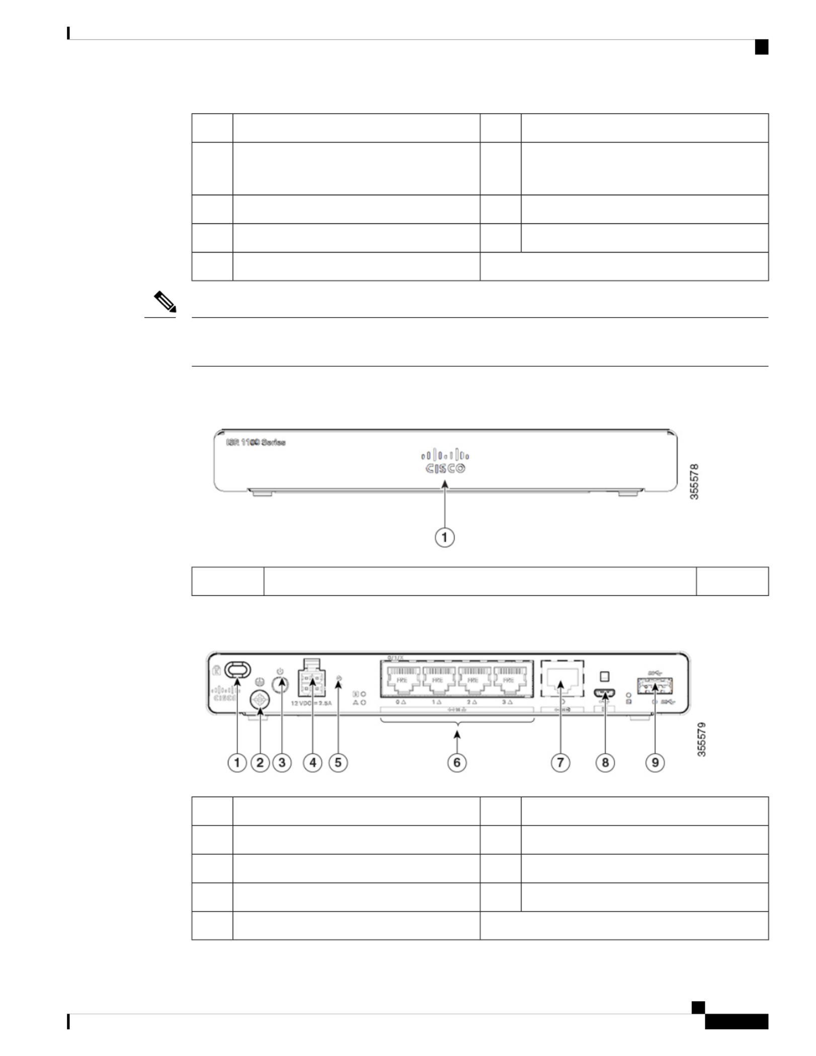
Figure 3: C1101-4P ISR - Front View
Non-illuminated Cisco Logo1
Figure 4: C1101-4P ISR - I/O View
Grounding2Kensington Lock Slot1
4-pin Power Connector4Power Switch3
LAN: 0-46Reset Button5
Micro USB Console8GE WAN7
USB3.09
Hardware Installation Guide for the Cisco 1000 Series Integrated Services Router
5
Overview of Cisco 1000 Series Integrated Services Routers
Chassis Views

Figure 5: C1101-4PLTEP-Bezel View
Non-illuminated Cisco logo1
Figure 6: C1101-4PLTEP - I/O View
4-pin Power Connector2Power Switch1
LAN:0-44Reset Button3
Micro-USB console Port6GE WAN5
Grounding8Pluggable7
Kensington Lock Slot9
Figure 7: C1109-4PLTE2P - Bezel View
Non-illuminated Cisco logo1
Main and Diversity Antenna2
Hardware Installation Guide for the Cisco 1000 Series Integrated Services Router
6
Overview of Cisco 1000 Series Integrated Services Routers
Chassis Views

Figure 8: C1109-2PLTE - I/O View
Grounding2Kensington Lock Slot1
Power Switch4Reset Button3
LAN: 0 & 164-pin Power Connector5
Micro-USB console Port8GE WAN7
Micro-SIM slots 0 and 110USB 3.09
Figure 9: C1109-4PLTE2PWX - I/O View
Power Switch2Grounding1
4-pin Power Connector4Reset Button3
GE WAN6LAN:0-45
Micro-USB console Port8USB 3.07
Kensington Lock Slot10Wifi Antenna9
Figure 10: C1121-4Px - Bezel View
Hardware Installation Guide for the Cisco 1000 Series Integrated Services Router
7
Overview of Cisco 1000 Series Integrated Services Routers
Chassis Views

Non-illuminated Cisco logo1
Figure 11: C1121-4P I/O View
Power Switch2Reset Button1
Ethernet Switch44-pin Power Connector3
GE WAN 0/0/0 -RJ456RJ-45 Stacked Connector5
Micro-USB console8GE WAN 0/0/0 -SFP7
Kensington Lock Slot10USB 3.09
Grounding11
Figure 12: C1121-4PLTEP I/O View
Power Switch2Reset Button1
Ethernet Switch44-pin Power Connector3
GE WAN 0/0/0 -RJ456GE 0/0/15
Micro-USB console8GE WAN 0/0/0 -SFP7
Pluggable10USB 3.09
Grounding12Kensington Lock Slot11
Hardware Installation Guide for the Cisco 1000 Series Integrated Services Router
8
Overview of Cisco 1000 Series Integrated Services Routers
Chassis Views

Figure 13: C1121(X)-8P - Bezel View
Non-illuminated Cisco logo1
Figure 14: C1121(X)-8P I/O View
Power Switch2Reset Button1
Ethernet Switch44-pin Power Connector3
GE WAN 0/0/0 -RJ456RJ-455
Micro-USB console8GE WAN 0/0/0 -SFP7
Kensington Lock Slot10USB 3.09
Grounding11
Figure 15: C1121-8PLTEP I/O View
Power Switch2Reset Button1
Ethernet Switch44-pin Power Connector3
GE WAN 0/0/0 -RJ456GE 0/0/15
Micro-USB console8GE WAN 0/0/0 -SFP7
Pluggable10USB 3.09
Hardware Installation Guide for the Cisco 1000 Series Integrated Services Router
9
Overview of Cisco 1000 Series Integrated Services Routers
Chassis Views

Grounding12Kensington Lock Slot11
Figure 16: C1121-8PLTEPWx Bezel View
Non-illuminated Cisco logo1
Figure 17: C1121(X)-8PLTEPW I/O View
Power Switch2Reset Button1
Ethernet Switch44-pin Power Connector3
GE 0/0/16Wi-Fi Status5
GE WAN 0/0/0 -SFP8GE WAN 0/0/0 -RJ457
USB 3.010Micro-USB console9
Kensington Lock Slot12Pluggable11
Grounding13
Figure 18: C1127X-8PLTEP Bezel View
Non-illuminated Cisco logo1
Hardware Installation Guide for the Cisco 1000 Series Integrated Services Router
10
Overview of Cisco 1000 Series Integrated Services Routers
Chassis Views

Figure 19: C1127X-8PLTEP IO Panel View
Power Switch2Reset Button1
Ethernet Switch44-pin Power Connector3
GE WAN 0/0/0 -RJ456RJ-455
Micro-USB console8GE WAN 0/0/0 -SFP7
DSL10Pluggable9
Grounding12Kensington Lock Slot11
Figure 20: C1128-8PLTEP Bezel View
Non-illuminated Cisco logo1
Figure 21: C1128-8PLTEP I/O Panel View
Power Switch2Reset Button1
Ethernet Switch44-pin Power Connector3
GE WAN 0/0/0 -RJ456USB 3.05
Micro-USB console8GE WAN 0/0/0 -SFP7
SHDSL10Pluggable9
Grounding12Kensington Lock Slot11
Hardware Installation Guide for the Cisco 1000 Series Integrated Services Router
11
Overview of Cisco 1000 Series Integrated Services Routers
Chassis Views

LED Indicators
The following figures and table summarizes the LED indicators that are located in the bezel or chassis of the
C111x series.
Figure 22: LED Indicators - Bezel Side
VPN2Status1
GPS4WLAN3
LTE DATA/SIM6LTE RSSI/Mode5
Cisco Logo7
Figure 23: LED Indicators - I/O Side
PoE LED2GE WAN Ports: 0-7 (0,2,4,6 at the top and
1,3,5,7 at the bottom)
1
GE0 LED4GE1 LED3
RJ-45 Console LED6USB LED5
Micro USB Console LED8USB Console7
DATA LED10CD LED9
Hardware Installation Guide for the Cisco 1000 Series Integrated Services Router
12
Overview of Cisco 1000 Series Integrated Services Routers
LED Indicators
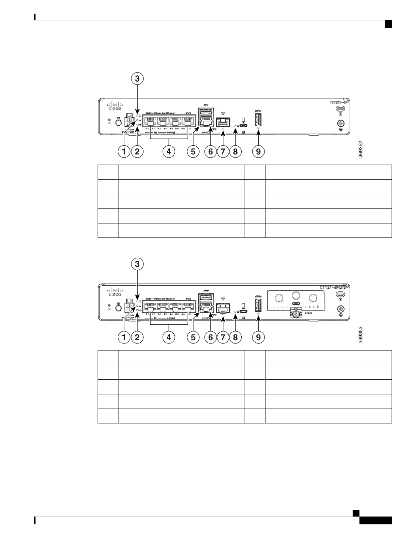
Figure 24: Cisco 1121-4Px LED Indicators
PoE LED2VPN1
Ethernet Switch Ports 0-34Status3
GE 0/0/1 LED6GE 0/0/0 RJ45 LED5
Micro USB Console LED8GE 0/0/0 RJ45 LED7
USB LED9
Figure 25: Cisco 1121-4PLTEP LED Indicators
PoE LED2VPN1
Ethernet Switch Ports 0-34Status3
GE 0/0/1 LED6GE 0/0/0 RJ45 LED5
Micro USB Console LED8GE 0/0/0 RJ45 LED7
USB LED9
Hardware Installation Guide for the Cisco 1000 Series Integrated Services Router
13
Overview of Cisco 1000 Series Integrated Services Routers
LED Indicators

Figure 26: Cisco 11x1(X)-8P/ C11x1(X)-8PLTEP LED Indicators
PoE LED2VPN1
Ethernet Switch Ports 0-7 (0,2,4,6 at the top
and 1,3,5,7 at the bottom)
4Status3
GE 0/0/1 LED6GE 0/0/0 RJ45 LED5
Micro USB Console LED8GE 0/0/0 RJ45 LED7
USB LED9
Figure 27: Cisco 11x1(X)-8PLTEPWx LED Indicators
PoE LED2VPN1
Ethernet Switch Ports 0-7 (0,2,4,6 at the top
and 1,3,5,7 at the bottom)
4Status3
GE 0/0/0 RJ45 LED6Wi-Fi5
GE 0/0/0 SFP LED8GE 0/0/1 LED7
Micro USB Console LED10USB LED9
Hardware Installation Guide for the Cisco 1000 Series Integrated Services Router
14
Overview of Cisco 1000 Series Integrated Services Routers
LED Indicators

Figure 28: Cisco 1126(X)-8PLTEP/ C1127(X)-8PxLTEP LED Indicators
PoE LED2VPN1
Ethernet Switch Ports 0-7 (0,2,4,6 at the top
and 1,3,5,7 at the bottom)
4Status3
USB5 LED6GE 0/0/0 RJ45 LED5
Micro USB Console LED8GE 0/0/0 SFP LED7
CD LED9
The following table summarizes the LED indicators that are located in the bezel or chassis of the C111x series.
Table 2: LED Indicators for C111x
Control SourceDescriptionLED ColorPort
Bezel sideIlluminated Cisco logo.
Indicates router power is
good.
BlueCisco Logo
Bezel side. All models.Steady Green - System
operates normally.
Green and AmberSTATUS
(System Status)
Off—System is not out of
reset or BIOS image is not
loadable.
Blinking Amber —
BIOS/Rommon is
booting.
Steady Amber —
BIOS/Rommon has
completed booting, and
the system is at the
Rommon prompt or
booting the platform
software.
Hardware Installation Guide for the Cisco 1000 Series Integrated Services Router
15
Overview of Cisco 1000 Series Integrated Services Routers
LED Indicators

Control SourceDescriptionLED ColorPort
Bezel sideOff—No tunnel.GreenVPN OK
Steady On— At least one
tunnel is up.
Bezel SideNo LEDs On—No
Service
Green and AmberLTE RSSI/Mode
1 LED On— RSSI is
under -100dBm.
2 LEDs On— Low RSSI,
-99dbm <> -90dBm.
3 LEDs On— Medium
RSSI -89dBm <>
-70dBm.
4 LEDs On— High RSSI,
> -69dBm.
Green— LTE
Amber— 3G
Bezel SideOff: GPS not configuredGreen
GPS
On: GPS configured
Blink: GPS Acquiring
Bezel sideGreen— Normal
operating condition with
at least one wireless client
association.
Green, Red, and Amber
WLAN
Red—Ethernet link is not
operational or Ethernet
failure.
Amber—Software
upgrade is in progress.
I/O sideOff— No linkGreenEthernet Switch GE LAN
Ports, Non-PoE
Steady On— link
Blink— TXD/RXD data
Hardware Installation Guide for the Cisco 1000 Series Integrated Services Router
16
Overview of Cisco 1000 Series Integrated Services Routers
LED Indicators

Control SourceDescriptionLED ColorPort
I/O sideOff— No link, no device
powered, PD denied
power, power delivery
fault PoE administratively
disabled.
Green Steady On— link;
if PoE device, power is
enabled.
Green Blink— TXD/RXD
data
Amber - PoE Fault
Green and AmberEthernet Switch GE LAN
Ports, with PoE
I/O sideGreen Steady On—
-53.5V PoE power supply
connected and all powered
port operating normally.
GreenPoE OK
Off — No -53.5V PoE
power supply connected
to router.
I/O sideOff— No linkGreenGE WAN Ports
Steady On— link
Blink— TXD/RXD data
I/O SideOff— ShutGreen
DSL CD
Green Blink— Training,
or no shut and cable
disconnected.
Green Steady On—
Trained
I/O SideOff— No Data ActivityGreen
DSL Data
Green Blink— TX/RX
Data
I/O sideGreen On— Console
enabled.
GreenConsole
I/O sideOff— No USB device
discovered.
GreenUSB Console
On— USB device
discovered.
Hardware Installation Guide for the Cisco 1000 Series Integrated Services Router
17
Overview of Cisco 1000 Series Integrated Services Routers
LED Indicators

Control SourceDescriptionLED ColorPort
I/O SideOff: No USB device
discovered.
GreenUSB
On: USB device
discovered.
Table 3: LED Indicators for C1101 and C1109
Control SourceDescriptionColorLED
I/OSystem Power Status
Off: No Power
Green Steady On:
Normal operation
Green Blink: Boot up
phase or in ROM Monitor
mode
Amber Steady on Or
Blink: Some issues with
the system.
Green+AmberPower
I/OVPN Status
Off: No tunnel
Steady on:At least one
tunnel is up
GreenVPN OK
I/OLink Activity
Off: No link
Steady on: Link
Blink: TXD/RXD Data
GreenEthernet Switch GE LAN
Ports
I/OLink Activity
Off: No link
Steady on: Link
Blink: TXD/RXD Data
GreenGE WAN Ports
Hardware Installation Guide for the Cisco 1000 Series Integrated Services Router
18
Overview of Cisco 1000 Series Integrated Services Routers
LED Indicators

Control SourceDescriptionColorLED
Bezel SideSingle LTE Modem (one
modem with SIM
switch-over capability)
Off: Modem not up or
modem up and no SIM
Amber Steady On:
Modem up, SIM installed
but not active.
Green Blink: LTE data
activity.
Green and AmberLTE DATA/SIM
(C1101-4PLTEPWz
C1101-4PLTEP/C1101-4PLTEPWx)
I/OWLAN Functions3-color LED: Green, Red
& Amber;
WLAN
(C1101-4PLTEPWx)
I/OUSB Console Status
OFF: USB console not
active
ON: USB console active
GreenUSB Console
I/OUSB 3.0 Status
OFF: No USB device
discovered
ON: USB device
discovered
USB activity
GreenUSB 3.0
Reset Button
The actuation of the Reset button is only recognized during ROMMON boot, that is, as the router comes to
the ROMMON prompt.
The Reset button does not require much force to be actuated. The Reset button should be actuated only with
a small implement such as the tip of a pen or a paper clip. When the Reset button is pressed at startup, the
system LED turns green.
For more information, see the "Reset Overview" section of the Cisco 1100 Software Configuration Guide.
Power Supply
C111x Series ISRs support PoE and PoE+ power to endpoints. The product power specifications are as follows:
• AC input voltage: Universal 100 to 240 VAC
• Frequency: 50 to 60 Hz
• Maximum output power: Up to 66W for non-PoE supply and upto 150W for PoE supply
Hardware Installation Guide for the Cisco 1000 Series Integrated Services Router
19
Overview of Cisco 1000 Series Integrated Services Routers
Reset Button

• Optional PoE and PoE+
• Output voltage: +12VDC for system power and -53.5VDC for PoE power
Slots and Interfaces
About Slots, Subslots, and Port Numbering
The Cisco 1100 series designates its interfaces using a 3-tuple notation that lists the slot, sub slot and port in
the format slot/sub-slot/port. The slot number is reserved for the mother board, which is "0". Each interface
type is allocated a sub slot and the port number is a unique port on the interface.
Table 4: Slot, Bay, and Port Numbering
Interface TypeSubslot
Ethernet LAN0
Ethernet WAN1
LTE2
DSL3
WIFI4
Specifications of Cisco 1100 Series Integrated Services Routers
For specifications on the Cisco 1100 Series ISRs, refer to the Cisco 1100 Series ISR Specifications document.
Periodic Inspection and Cleaning
We recommend that you periodically inspect and clean the external surface of the router is recommended to
minimize the negative impact of environmental dust or debris. The frequency of inspection and cleaning is
dependent upon the severity of the environmental conditions, but we recommend a minimum once every six
months. Cleaning involves vacuuming router air intake and exhaust vents.
Sites with ambient temperatures consistently above 25°C or 77°F and with potentially high levels of dust or
debris might require periodic preventative maintenance cleaning.
Note
Hardware Installation Guide for the Cisco 1000 Series Integrated Services Router
20
Overview of Cisco 1000 Series Integrated Services Routers
Slots and Interfaces

C H A P T E R 2
Prepare for Router Installation
Before you install the Cisco 1100 Series Integrated Services Routers, you must prepare your site for the
installation. This chapter provides pre-installation information, such as recommendations and requirements
that should be considered before installing your router.
See the following sections to prepare for installation:
•Safety Recommendations, on page 21
•General Site Requirements, on page 22
•Rack Requirements, on page 23
•Router Environmental Requirements, on page 24
•Power Guidelines and Requirements, on page 25
•Network Cabling Specifications, on page 25
•Required Tools and Equipment for Installation and Maintenance, on page 27
Safety Recommendations
IMPORTANT SAFETY INSTRUCTIONS
This warning symbol means danger. You are in a situation that could cause bodily injury. Before you work
on any equipment, be aware of the hazards involved with electrical circuitry and be familiar with standard
practices for preventing accidents. Use the statement number provided at the end of each warning to locate
its translation in the translated safety warnings that accompanied this device. Statement 1071
SAVE THESE INSTRUCTIONS
Warning
Ultimate disposal of this product should be handled according to all national laws and regulations. Statement
1040.
Warning
Hardware Installation Guide for the Cisco 1000 Series Integrated Services Router
21

Safety With Electricity
Only trained and qualified personnel should be allowed to install or replace this equipment Statement 1030
Warning
Do not locate the antenna near overhead power lines or other electric light or power circuits, or where it can
come into contact with such circuits. When installing the antenna, take extreme care not to come into contact
with such circuits, as they may cause serious injury or death. For proper installation and grounding of the
antenna, please refer to national and local codes (for example, U.S.:NFPA 70, National Electrical Code, Article
810, Canada:Canadian Electrical Code, Section 54). Statement 1052
Warning
Prevent Electrostatic Discharge Damage
Electrostatic discharge (ESD) can damage equipment and impair electrical circuitry. It can occur if electronic
printed circuit cards are improperly handled and can cause complete or intermittent failures. Always follow
ESD prevention procedures when removing and replacing modules:
• Ensure that the router chassis is electrically connected to ground.
• Wear an ESD-preventive wrist strap, ensuring that it makes good skin contact. Connect the clip to an
unpainted surface of the chassis frame to channel unwanted ESD voltages safely to ground. To guard
against ESD damage and shocks, the wrist strap and cord must operate effectively.
• If no wrist strap is available, ground yourself by touching a metal part of the chassis.
For the safety of your equipment, periodically check the resistance value of the anti-static strap. It should be
between 1 and 10 megohms (Mohm).
Caution
General Site Requirements
This section describes the requirements your site must meet for the safe installation and operation of your
router. Ensure that the site is properly prepared before beginning installation. If you are experiencing shutdowns
or unusually high errors with your existing equipment, the guidelines provided in this section can also help
you isolate the cause of failures and prevent future problems.
Installation of the equipment must comply with local and national electrical codes. Statement 1074
Warning
Connect the Chassis to Earth Ground—To reduce the risk of electric shock, the chassis of this equipment
needs to be connected to permanent earth ground during normal use. Statement 445
Warning
Hardware Installation Guide for the Cisco 1000 Series Integrated Services Router
22
Prepare for Router Installation
Safety With Electricity

This product relies on the building’s installation for short-circuit (overcurrent) protection. Ensure that the
protective device is rated not greater than: 20A. Statement 1005
Warning
To prevent bodily injury when mounting or servicing this unit in a rack, you must take special precautions to
ensure that the system remains stable. The following guidelines are provided to ensure your safety:
• This unit should be mounted at the bottom of the rack if it is the only unit in the rack.
• When mounting this unit in a partially filled rack, load the rack from the bottom to the top with the
heaviest component at the bottom of the rack.
• If the rack is provided with stabilizing devices, install the stabilizers before mounting or servicing the
unit in the rack. Statement 1006.
Warning
To prevent the system from overheating, do not operate the devices in an area that exceeds the maximum
recommended ambient temperature:
Statement 1047
Warning
For connections outside the building where the equipment is installed, the following ports must be connected
through an approved network termination unit with integral circuit protection, LAN, PoE. Statement 1044.
Warning
To prevent airflow restriction, allow clearance around the ventilation openings to be at least: 1.75 in. (4.4
cm). Statement 1076.
Warning
Site Selection Guidelines
The Cisco 1100 Series ISRs require specific environmental operating conditions. Temperature, humidity,
altitude, and vibration can affect the performance and reliability of the router. The following sections provide
specific information to help you plan for the proper operating environment.
The Cisco 1100 Series ISRs are designed to meet the industry EMC, safety, and environmental standards
described in the Regulatory Compliance and Safety Information for the Cisco 1100 Series ISR document.
Rack Requirements
For the Cisco <platform name>, use brackets with a 19-inch rack.
Hardware Installation Guide for the Cisco 1000 Series Integrated Services Router
23
Prepare for Router Installation
Site Selection Guidelines

Rack requirements is applicable only for <platform name> routers.
Note
The following information can help you plan your equipment rack configuration:
• Allow clearance around the rack for maintenance.
• Allow at least one rack unit of vertical space between routers; more clearance is required when stacking
multiple Cisco <platform name>. Provide adequate heat removal mechanism to keep the surrounding
air temperature well within the specified operating temperature condition.
More spacing may be required depending on the installation environment.
Note
• Enclosed racks must have adequate ventilation. Ensure that the rack is not congested, because each router
generates heat. An enclosed rack should have louvered sides and a fan to provide cooling air. Heat
generated by equipment near the bottom of the rack can be drawn upward into the intake ports of the
equipment above it.
• When mounting a chassis in an open rack, ensure that the rack frame does not block the intake or exhaust
ports. If the chassis is installed on slides, check the position of the chassis when it is seated in the rack.
Router Environmental Requirements
Cisco 1100 Series ISRs can be placed on a desktop, installed in a rack, or mounted on a wall. The location of
your router and the layout of your equipment rack or wiring room are extremely important considerations for
proper operation. Equipment placed too close together, inadequate ventilation, and inaccessible panels can
cause malfunctions and shutdowns, and can make maintenance difficult. Plan for access to both front and rear
panels of the router.
Only C111x Series support rack installation and DIN Rail mounting.
Note
When planning your site layout and equipment locations, refer to the General Site Requirements , section. If
you are currently experiencing shutdowns or an unusually high number of errors with your existing equipment,
these precautions and recommendations may help you isolate the cause of failure and prevent future problems.
• Ensure that the room where your router operates has adequate air circulation. Electrical equipment
generates heat. Without adequate air circulation, ambient air temperature may not cool equipment to
acceptable operating temperatures.
• Always follow ESD-prevention procedures described in the Preventing Electrostatic Discharge Damage
to avoid damage to equipment. Damage from static discharge can cause immediate or intermittent
equipment failure.
• Baffles can help to isolate exhaust air from intake air, which also helps to draw cooling air through the
chassis. The best placement of the baffles depends on the airflow patterns in the rack, which can be found
by experimenting with different configurations.
Hardware Installation Guide for the Cisco 1000 Series Integrated Services Router
24
Prepare for Router Installation
Router Environmental Requirements

• When equipment installed in a rack (particularly in an enclosed rack) fails, try operating the equipment
by itself, if possible. Power off other equipment in the rack (and in adjacent racks) to allow the router
under test a maximum of cooling air and clean power.
Power Guidelines and Requirements
Check the power at your site to ensure that you are receiving power that is free of spikes and noise. Install a
power conditioner if necessary.
Power Guidelines and Requirements lists power requirements for the Cisco <platform name>.
Table 5: Power Requirements for <platform name>
Output RatedInput RatedPower Source
12 VDC, 5.5A100-240V, 2A66W AC Power Adapter
(PWR-66W-AC-V2)
12V, 4.6A, -53.5V 1.12A100-240VAC, 2A, 50-60 Hz115W AC Power Adapter
(PWR-115W-AC)
12V , 2.5A100-240 VAC, 1A30W AC Power Adapter
(PWR-30W-AC)
12V 5.5A, -53.5 1.5A100-240 VAC, 2A150W AC Power Adapter
(PWR-150W-AC)
12 VDC, 5.5A24 V DC Nominal (19.7V DC to
30 V DC input range)
66W DC Power Adapter
(PWR-66W-I-DC)
Network Cabling Specifications
The following sections describe the cables and thee specifications required to install Cisco 1100 Series ISRs:
Console Port Connections
The C111x has both EIA/TIA-232 asynchronous (RJ-45) and USB 5-pin micro Type B, 2.0 compliant serial
console ports. The console ports do not have any hardware flow control. Shielded USB cables with properly
terminated shields are recommended.
EIA/TIA-232
Depending on the cable and the adapter used, this port appears as a DTE or DCE device at the end of the
cable. Only one port can be used at the same time.
Hardware Installation Guide for the Cisco 1000 Series Integrated Services Router
25
Prepare for Router Installation
Power Guidelines and Requirements

The default parameters for the console port are 9600 baud, 8 data bits, 1 stop bit, and no parity. The console
port does not support hardware flow control. For detailed information about installing a console terminal, see
the Connecting to a Console Terminal or Modem section.
For cable and port pinouts, see the Cisco Modular Access Router Cable Specifications document located on
Cisco.com.
USB Serial Console
The USB serial console port connects directly to the USB connector of a PC using a USB Type A to 5-pin
micro USB Type-B cable. The USB Console supports full speed (12Mb/s) operation. The console port does
not support hardware flow control.
Always use shielded USB cables with a properly terminated shield.
Note
The default parameters for the console port are 9600 baud, 8 data bits, no parity, and 1 stop bit. For detailed
information about installing a console terminal, see the Connecting to a Console Terminal or Modem section
on page 3-19.
For operation with a Microsoft Windows OS version older than Windows 7, the Cisco Windows USB Console
Driver must be installed on any PC connected to the console port. If the driver is not installed, prompts guide
you through a simple installation process.
The Cisco Windows USB Console Driver allows plugging and unplugging the USB cable from the console
port without affecting Windows HyperTerminal operations. No special drivers are needed for Mac OS X or
Linux.
Only one console port can be active at a time. When a cable is plugged into the USB console port, the RJ-45
port becomes inactive. Conversely, when the USB cable is removed from the USB port, the RJ-45 port becomes
active.
Baud rates for the USB console port are 1200, 2400, 4800, 9600, 19200, 38400, 57600, and 115200 bps.
4- pin micro USB Type-B connectors are easily confused with 5-pin micro USB Type-B connectors. Only
the 5-pin micro USB Type-B is supported.
Note
USB Console OS Compatibility
• Windows 10, Windows 8, Windows 7, Windows 2000, Window XP 32 bit, Windows Vista 32 bit
• Mac OS X version 10.5.4
• Redhat / Fedora Core 10 with kernel 2.6.27.5-117
• Ubuntu 8.10 with kernel 2.6.27-11
• Debian 5.0 with kernel 2.6
• Suse 11.1 with kernel 2.6.27.7-9
Hardware Installation Guide for the Cisco 1000 Series Integrated Services Router
26
Prepare for Router Installation
USB Serial Console

Console Port Considerations
The router includes an asynchronous serial console port. The console ports provide access to the router using
a console terminal connected to the console port. This section discusses important cabling information to
consider before connecting the router to a console terminal or modem.
Console terminals send data at speeds slower than modems do; therefore, the console port is ideally suited
for use with console terminals.
Preparing for Network Connections
When setting up your router, consider distance limitations and potential electromagnetic interference (EMI)
as defined by the applicable local and international regulations.
Network connection considerations are provided for:
See the following online document for more information about network connections and interfaces:
• Cisco Modular Access Router Cable Specifications
Ethernet Connections
The IEEE has established Ethernet as standard IEEE 802.3. The routers support the following Ethernet
implementations:
• 1000BASE-T—1000 Mb/s full-duplex transmission over a Category 5 or better unshielded twisted-pair
(UTP) cable. Supports the Ethernet maximum length of 328 feet (100 meters).
• 100BASE-T—100 Mb/s full-duplex transmission over a Category 5 or better unshielded twisted-pair
(UTP) cable. Supports the Ethernet maximum length of 328 feet (100 meters).
• 10BASE-T—10 Mb/s full-duplex transmission over a Category 5 or better unshielded twisted-pair (UTP)
cable. Supports the Ethernet maximum length of 328 feet (100 meters).
See the Cisco Modular Access Router Cable Specifications document at Cisco.com for information about
Ethernet cables, connectors, and pinouts.
RequiredToolsand EquipmentforInstallation andMaintenance
You need the following tools and equipment to install and upgrade the router and its components:
• ESD-preventive cord and wrist strap
• Number 2 Phillips screwdriver
• Phillips screwdrivers: small, 3/16-in. (4 to 5 mm) and medium, 1/4-in. (6 to 7 mm)
• To install or remove modules
• To remove the cover, if you are upgrading memory or other components
• Screws that fit your rack
• Wire crimper
• Wire for connecting the chassis to an earth ground:
Hardware Installation Guide for the Cisco 1000 Series Integrated Services Router
27
Prepare for Router Installation
Console Port Considerations

• AWG 14 (2 mm²) or larger wire.
• An appropriate user-supplied UL or CSA certified ring terminal with an inner diameter of 1/4 in. (5 to
7 mm)
Hardware Installation Guide for the Cisco 1000 Series Integrated Services Router
28
Prepare for Router Installation
Required Tools and Equipment for Installation and Maintenance

C H A P T E R 3
Install and Connect the Router
This chapter describes how to install and connect Cisco 1000 Series Integrated Services Router (ISR) to LAN
and WAN networks.
Read the installation instructions before using, installing or connecting the system to the power source.
Statement 1004
Warning
Installing the Cisco 1000 Series Integrated Services Routers involve these tasks:
•Unpack the Router, on page 29
•Set up Router on Desktop, Rack, or Wall, on page 29
•Connect Power Cable, on page 47
•Connect the Router to a Console, on page 49
•Connect WAN and LAN Interfaces, on page 53
•Configure the Router at Startup, on page 54
Unpack the Router
Unpack the router only when you are ready to install it. If the installation site is not ready, to prevent accidental
damage, keep the chassis in its shipping container until you are ready to install.
The router, accessory kit, publications, and any optional equipment you order may be shipped in more than
one container. When you unpack the containers, check the packing list to ensure that you have received all
listed items.
Set up Router on Desktop, Rack, or Wall
After unpacking, based on your requirements, you can set up a Cisco 1100 Series Integrated Services Routers
(ISRs) on a desktop, a rack, or the wall.
Hardware Installation Guide for the Cisco 1000 Series Integrated Services Router
29

You can install external modules before or after mounting a router. However, if you choose to install the
external modules after mounting the router on the rack or wall, ensure that you have optimal access to the
back/front panel of the router.
For information on modules and Field Replaceable Units (FRUs), see the Install and Upgrade Modules and
FRUs section.
Note
Depending on the model, the available options for mounting a Cisco 1100 ISR are:
Table 6: Models and Mounting Options
Mounting OptionsModel
Desktop Rack Mount Wall Mount using Key-hole Slots Wall Mount, , ,
using-Din-Rail
C111x and C1111X
Desktop Wall Mount using Key-hole Slots,C1101-4P
Desktop Wall Mount using Key-Hole Slots,C1101-4PLTEPWx
Desktop Wall Mount using Key-Hole Slots, ,C1109-2PLTExx
Desktop Rack Mounting using Din-Rail Brackets, , Under DeskC1121-4Px
Desktop Rack Mounting using Din-Rail Brackets, , Under DeskC1126(X)-8PLTEP
Desktop Rack Mounting using Din-Rail Brackets, , Under DeskC1128(X)-8PLTEP
If you choose to setup the router on a desktop, you can place the router on a desktop, bench top or on a shelf.
Rack Mount
The router is shipped with rack mounting brackets that are to be secured on the sides of the chassis. You must
first secure rack mounting brackets on the chassis before you set up the chassis on the rack.
Do not stack multiple Cisco 1000 ISRs when mounting the routers on a table top.
Caution
When mounting Cisco 1000 ISRs on a rack, ensure that there is ample surrounding space. This ensures more
heat removal, which in turn will enable the surrounding air temperature to stay within the specified operating
conditions.
Note
Attach the Brackets for C111x
This procedure describes how to attach the brackets on the router chassis:
Hardware Installation Guide for the Cisco 1000 Series Integrated Services Router
30
Install and Connect the Router
Rack Mount

Step 1 Secure the brackets to the router chassis (on the left) as shown in figure below:
Example:
Figure 29: Bracket Installation for Left-Side Mounting - C111x
Step 2 Similarly, secure the brackets on the right-side of the chassis for mounting the router.
Attach the Rack Mounting Brackets for C112x
This procedure describes how to attach the brackets on the router chassis:
Step 1 Remove the 6 screws from the bottom of the chassis.
Step 2 Place the platform into the bottom tray.
Step 3 Secure the original screws from the bottom side of the tray.
Example:
Hardware Installation Guide for the Cisco 1000 Series Integrated Services Router
31
Install and Connect the Router
Attach the Rack Mounting Brackets for C112x
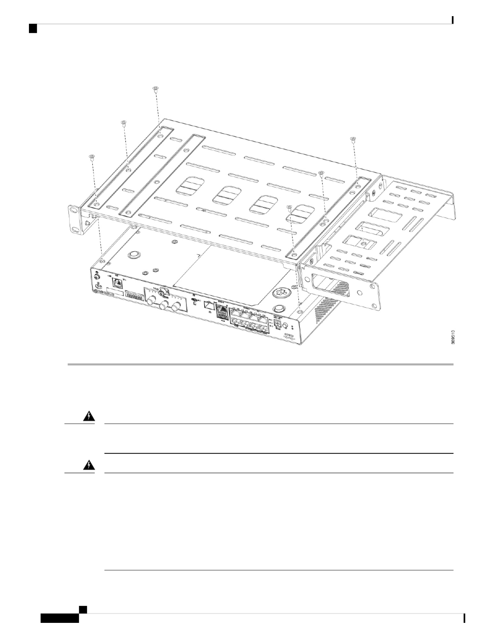
Figure 30: Bracket Installation for C1121-4Px, C1126-8PLTEP and C1128-8PLTEP
Mount the Router
Before mounting the router on to the rack, refer to the following safety warning statements:
To prevent airflow restriction, allow clearance around the ventilation openings to be at least: 1.75 in. (4.4
cm). Statement 1076.
Warning
• To prevent bodily injury when mounting or servicing this unit in a rack, you must take special precautions
to ensure that the system remains stable. The following guidelines are provided to ensure your safety:
• This unit should be mounted at the bottom of the rack if it is the only unit in the rack.
• When mounting this unit in a partially filled rack, load the rack from the bottom to the top with the
heaviest component at the bottom of the rack.
• If the rack is provided with stabilizing devices, install the stabilizers before mounting or servicing the
unit in the rack. Statement 1006.
Warning
Hardware Installation Guide for the Cisco 1000 Series Integrated Services Router
32
Install and Connect the Router
Mount the Router
Termékspecifikációk
| Márka: | Cisco |
| Kategória: | router |
| Modell: | C1101-4PLTEP |
Szüksége van segítségre?
Ha segítségre van szüksége Cisco C1101-4PLTEP, tegyen fel kérdést alább, és más felhasználók válaszolnak Önnek
Útmutatók router Cisco

2 Október 2024
18 Szeptember 2024
2 Szeptember 2024
24 Augusztus 2024
24 Augusztus 2024
23 Augusztus 2024
23 Augusztus 2024
3 Augusztus 2024
3 Augusztus 2024
2 Augusztus 2024
Útmutatók router
- router Samsung
- router Acer
- router Milwaukee
- router Bosch
- router AEG
- router StarTech.com
- router Einhell
- router Nokia
- router HP
- router Makita
- router BenQ
- router Apple
- router Ubiquiti Networks
- router Siemens
- router TP-Link
- router Medion
- router Motorola
- router Vimar
- router LogiLink
- router Alcatel
- router Roland
- router TCL
- router Digitus
- router Zebra
- router Xiaomi
- router TRENDnet
- router Mercusys
- router AVM
- router EZVIZ
- router Dell
- router Lancom
- router Strong
- router Gigabyte
- router Conceptronic
- router Thomson
- router Juniper
- router Kyocera
- router Hikvision
- router Keewifi
- router Vivanco
- router Netgear
- router Huawei
- router Asus
- router Vtech
- router Hama
- router Zoom
- router Renkforce
- router Synology
- router Draytek
- router Iogear
- router Güde
- router Hitachi
- router Mikrotik
- router Toolcraft
- router ZyXEL
- router SPL
- router Dahua Technology
- router Smart-AVI
- router Black & Decker
- router Devolo
- router Planet
- router Tenda
- router BT
- router Black Box
- router MSI
- router Gembird
- router PowerPlus
- router ATen
- router Google
- router Metabo
- router Bea-fon
- router ZTE
- router Edimax
- router Vodafone
- router ModeCom
- router HiKOKI
- router Foscam
- router Milan
- router Manhattan
- router Kogan
- router Festool
- router EnGenius
- router Sigma
- router Western Digital
- router D-Link
- router Media-Tech
- router Blustream
- router Milesight
- router Moxa
- router Sagem
- router Razer
- router Trust
- router Porter-Cable
- router Konig
- router Alfa
- router MuxLab
- router DeWalt
- router AVMATRIX
- router IFM
- router A-NeuVideo
- router Atlona
- router Schneider
- router AJA
- router Lindy
- router Cudy
- router Barco
- router QNAP
- router NEC
- router Silverline
- router Cotech
- router Siig
- router Gefen
- router Kathrein
- router Avenview
- router Lantronix
- router Technicolor
- router FSR
- router Topcom
- router Holzmann
- router Arris
- router Anker
- router I-TEC
- router Keenetic
- router Linksys
- router Teltonika
- router Sitecom
- router Intelix
- router Comprehensive
- router Ocean Matrix
- router Digitalinx
- router Alfatron
- router Belkin
- router RGBlink
- router Kopul
- router KanexPro
- router Key Digital
- router Kramer
- router BZBGear
- router UPC
- router Allnet
- router Allied Telesis
- router Airlive
- router Proximus
- router Skil
- router Eminent
- router Nilox
- router Sonos
- router Patton
- router Techly
- router Totolink
- router KPN
- router Netis
- router Envivo
- router Buffalo
- router Nest
- router LevelOne
- router ICIDU
- router Clas Ohlson
- router AT&T
- router Sweex
- router Aruba
- router Phicomm
- router Kasda
- router Jung
- router Digi
- router Verizon
- router Billion
- router T-Mobile
- router RAVPower
- router Hawking Technologies
- router Nexxt
- router Beafon
- router Kraun
- router LTS
- router Zolid
- router Sagemcom
- router Telstra
- router Eero
- router Advantech
- router Mercku
- router Hercules
- router Xantech
- router Intellinet
- router Arcadyan
- router Digiconnect
- router Ubee
- router SMC
- router Tele 2
- router Peak
- router CradlePoint
- router Davolink
- router Sixnet
- router 7inova
- router AVPro Edge
- router F-Secure
- router Rosewill
- router Digicom
- router Sabrent
- router On Networks
- router PENTAGRAM
- router Leoxsys
- router Readynet
- router OneAccess
- router Accelerated
- router Nexaira
- router Hamlet
- router Approx
- router T-com
- router Amped Wireless
- router Cambium Networks
- router 3Com
- router WyreStorm
- router Ruckus Wireless
- router Dovado
- router Mach Power
- router EXSYS
- router NetComm
- router Comtrend
- router Premiertek
- router GL.iNet
- router Shinybow
- router Edgewater
- router Atlantis Land
- router Lumantek
- router Starlink
- router PulseAudio
- router Predator
- router Evolution
- router Luxul
- router StarIink
- router Silentwind
- router Keezel
- router United Telecom
- router Wisetiger
Legújabb útmutatók router

9 Április 2025

9 Április 2025
9 Április 2025

31 Március 2025
30 Március 2025
30 Március 2025
30 Március 2025
30 Március 2025
30 Március 2025
23 Március 2025