Használati útmutató Ashly PEMA 4125.70C
Olvassa el alább 📖 a magyar nyelvű használati útmutatót Ashly PEMA 4125.70C (28 oldal) a Vevő kategóriában. Ezt az útmutatót 10 ember találta hasznosnak és 2 felhasználó értékelte átlagosan 4.5 csillagra
Oldal 1/28

ASHLY AUDIO INC.
847 Holt Road Webster, NY 14580-9103 Phone: (585) 872-0010
Toll-Free: (800) 828-6308 Fax: (585) 872-0739 ashly.com

Operating Manual - Pema Protea Equipped Media Amplier
2
Important Safety Instructions
Consignes de sécurité à lire attentivement
The lightning flash with arrowhead symbol, within an equilateral triangle,
is intended to alert the user to the presence of uninsulated "dangerous
voltage" within the product's enclosure that may be of sufficient magnitude
to constitute a risk of electric shock to persons. The exclamation point
within an equilateral triangle is intended to alert the user to the presence
of important operating and maintenance instructions in the literature ac-
companying the device.
Le symbole de la flèche dans un triangle équilateral symbolisant la foudre
est prévu pour sensibiliser l’utilisateur à la présence de tension de voltage
non isolée à l’intérieur de l’appareil. Elle pourrait constituer un danger de
risque de décharge électrique pour les utilisateurs. Le point d’exclamation
dans le triangle équilatérale alerte l’utilisateur de la présence de consignes
qu’il doit d’abord consulter avant d’utiliser l’appareil.
1. Read these instructions.
2. Keep these instructions.
3. Heed all warnings.
4. Follow all instructions.
5. To reduce the risk of re or electric shock, do not expose this apparatus to
rain or moisture.
6. Do not use this apparatus near water.
7. Clean only with dry cloth.
8. Do not block any ventilation openings. Install in accordance with the manu-
facturer’s instructions.
9. Do not install near any heat sources such as radiators, heat registers,
stoves, or other apparatus.
10. Do not defeat the safety purpose of the polarized or grounding-type plug. A
polarized plug has two blades with one wider than the other. A grounding type
plug has two blades and a third grounding prong. The wide blade or the third
prong are provided for your safety. If the provided plug does not t into your
outlet, consult an electrician for replacement of the obsolete outlet.
11. Protect the power cord from being walked on or pinched particularly at plugs,
convenience receptacles, and the point where they exit from the apparatus.
12. Only use attachments/accessories specied by the manufacturer.
13. Use only with the cart, stand, tripod, bracket, or table specied by the
manufacturer, or sold with the apparatus. When a cart is used, use caution when
moving the cart/apparatus combination to avoid injury from tip-over.
14. Unplug this apparatus during lightning storms or when unused for long
periods of time.
15. Refer all servicing to qualied service personnel. Servicing is required when
the apparatus has been damaged in any way, such as power-supply cord or plug
is damaged, liquid has been spilled or objects have fallen into the apparatus, the
apparatus has been exposed to rain or moisture, does not operate normally, or
has been dropped.
1. Lisez ces instructions.
2. Conservez ces instructions.
3. Observez les avertissements.
4. Suivez ces instructions.
5. Pour réduire le risque de feu ou la décharge électrique, ne pas exposer cet
appareil pour pleuvoir ou l'humidité.
6. Ne pas utiliser l’appareil près de l’eau.
7. Le nettoyer à l’aide d’un tissus sec.
8. Ne pas bloquer les ouvertures de ventilation, installer selon les consignes du
fabricant.
9. Eloigner des sources de chaleur tel: radiateurs, fourneaux ou autres appareils
qui produisent de la chaleur.
10. Ne pas modier ou amputer le système de la mise à terre. Une prise avec
mise à terre comprend deux lames dont une plus large ainsi qu’une mise à
terre: ne pas la couper ou la modier. Si la prise murale n’accepte pas la che,
consulter un électricien pour qu’il remplace la prise désuète.
11. Protéger le cordon de secteur contre tous bris ou pincement qui pourraient
l’endommager, soit à la che murale ou à l’appareil.
12. N’employer que les accessoires recommandés par le fabricant.
13. N’utiliser qu’avec les systèmes de xation,chariots, trépied ou autres, ap-
prouvés par le fabricant ou vendus avec l’appareil.
14. Débrancher l’appareil lors des orages électriques ou si inutilisé pendant une
longue période de temps.
15. Un entretient effectué par un centre de service accrédité est exigé si
l’appareil a été endommagé de quelque façon: si il a été exposé à la pluie,,
l’humidité ou s’il ne fonctionne pas normalement ou qu’il a été échappé.
FCC Compliance
This device complies with part 15 of the FCC Rules. Operation is subject to the following two conditions:
1. This device may not cause harmful interference
2. This device must accept any interference received, including interference that may cause undesired operation
Note: This equipment has been tested and found to comply with the limits for a Class B digital device, pursuant to part 15 of the FCC Rules. These limits are designed to provide reasonable
protection against harmful interference in both a commercial and residential installation. This equipment generates, uses and can radiate radio frequency energy and, if not installed and used
in accordance with the instructions, may cause harmful interference to radio communications. However, there is no guarantee that interference will not occur in a particular installation. If this
equipment does cause harmful interference to radio or television reception, which can be determined by turning the equipment off and on, the user is encouraged to try to correct the interference
by one or more of the following measures:
- Reorient or relocate the receiving antenna.
- Increase the separation between the equipment and receiver.
- Connect the equipment into an outlet on a circuit different from that to which the receiver is connected.
- Consult the dealer or an experienced radio/TV technician for help..

3
Operating Manual - Pema Protea Equipped Media Amplier
WARNING:
THIS APPARATUS MUST BE EARTHED
Table Of Contents
1 Introduction and Unpacking 4
2 Pema Amplier Models 5
21 Product Overview 5
22 Installation Requirements 5
23 Ethernet Communications Requirements 5
24 Front Panel Features 6
25 Rear Panel Features 7
26 Amplier Protection 8
3 Proteane Control Software 8
31 Installing Software 8
32 Device Options 10
33 Preset Options 10
34 Device Control Tabs 11
34a Control Surface 11
34b Security 13
34c Network Properties 13
34d DSP Controls 14
34e Input Source 16
34f Metering 16
34g Event Scheduler 16
34h Fault Log 16
4 Pema Remote Control 17
41 Remote Control Devices 17
41a WR-1 Level Control 17
41b WR-15 Level Control and Preset Recall Switch 17
41c WR-2 Preset Recall Switches 17
41d WR-5 Programmable Button Control (and RPS-18 Remote Power Supply) 17
41e RD-8C or RW-8C Programmable Fader Controller 18
41f INA-1 Inline RS-232 Adapter 18
41g neWR-5 Networked Programmable Button Controller 18
41h FR-8 or FR-16 Programmable Fader Controller 18
41i Ashly Remote Application for iPad
® 18
42 Remote Control Functions 19
42a Power Switch Disable 19
42b On/Off Remote Standby 19
42c Remote Preset Recall 20
42d Remote Gain Control 20
42e Remote Channel Mute 21
42f Remote Zone Input Source Selection 21
5 Troubleshooting 22
6 Specications 24
7 Warranty 27
8 Block Diagram 28

Operating Manual - Pema Protea Equipped Media Amplier
4
1. INTRODUCTION
Thank you for your purchase of this Pema series Protea Equipped Media Amplifier. This single audio solution com-
bines state of the art, light weight, high efficiency switching amplifier technology, integrated Ethernet control, comprehensive
Protea DSP processing and matrix mixing, optional Dante
® or CobraNet® network audio, and remote control options. Please
read this entire manual to fully understand the features and capabilities of this product.
Standard Pema Features:
• 8x8 DSP Matrix with 4 or 8 channel power amplifiers
• 250W/channel and 125W/channel models
• Low Z output or constant voltage models available
• CobraNet or Dante available as a factory installed option
• Eight analog inputs use +4dBu balanced Euroblock and -10dBV unbalanced summed mono RCA connectors
• Mic preamps with switchable +15V phantom power on all Mic/Line inputs
• Switchable transformer isolated -20dBu TEL-PBX 600 Ohm input on Channel 1
• Proteane software with comprehensive DSP tool set, matrix router/mixer, metering, event scheduler and event log
• DSP tools include auto-mixer, ambient noise compensation, feedback suppressor, autoleveler, and much more
• Balanced, post DSP analog preamp outputs for every amplifier output channel
• Compatible with Ashly network and serial data remote controllers, plus Ashly Remote app for iPad
®
• Passive remote control options include remote standby, contact closure preset recall, and remote DC level control
• Front panel attenuators and metering
• Five year warranty
About Ashly
Ashly Audio was founded in 1974 by a group of recording engineers, concert sound professionals, and electronics design-
ers. The first products were elaborate custom consoles for friends and associates, but business quickly spread to new clients and
the business grew. The philosophy we established from the very beginning holds true today: to offer only the highest quality
audio tools at an affordable cost to the professional user – ensuring reliability and long life. Many years later, Ashly remains
committed to these principles.
Unpacking
As a part of our system of quality control, every Ashly product is carefully inspected before leaving the factory to ensure
flawless appearance. After unpacking, please inspect for any physical damage. Save the shipping carton and all packing ma-
terials, as they were carefully designed to reduce to a minimum the possibility of transportation damage should the unit again
require packing and shipping. In the event that damage has occurred, immediately notify your dealer so that a written claim to
cover the damages can be initiated.
The right to any claim against a public carrier can be forfeited if the carrier is not notified promptly and if the shipping carton
and packing materials are not available for inspection by the carrier. Save all packing materials until the claim has been settled.

5
Operating Manual - Pema Protea Equipped Media Amplier
2. PEMA AMPLIFIER MODELS
2.1 Product Overview
The Pema series of amplifiers are available in the following 120 VAC or 230 VAC mains configurations. Each model can
have an optional factory installed CobraNet or Dante network audio module. Constant voltage amplifiers can include 25V, 70V,
and 100V output models.
- Eight input, four 125W amp channels, low Z (speaker), or constant voltage (High Z) output models.Pema 4125
- Eight input, eight 125W amp channels, low Z (speaker), or constant voltage (High Z) output models.Pema 8125
- Eight input, four 250W amp channels, low Z (speaker), or constant voltage (High Z) output models.Pema 4250
- Eight input, eight 250W amp channels, low Z (speaker), or constant voltage (High Z) output models.Pema 8250
2.2 Installation Requirements
Each Pema model is 2RU, and weighs <22 pounds (10kg). The model number, mains voltage, and power consumption
are indicated on the back panel beneath the AC inlet.
Caution: Before mounting or wiring the unit, always disconnect it from the mains. Use four screws when mounting
the amplifier to the front rack rails. Rear support is also recommended, especially for mobile or touring use. Air flow vents
for cooling the amplifier require the front panel to have access to ambient room temperature air. Cool air is drawn in from the
front and blown out the sides. It is not necessary to leave a space above or below the amplifier in the rack. To reduce the risk
of fire or electric shock, do not expose this apparatus to rain or moisture. Before connecting to mains power, make sure that
the controls, software, and wiring are all set to the configuration needed for your particular application. Failure to do so could
result in damage to the unit or other components in the system.
Wiring: Always use high quality shielded cable for input signals, and use balanced input signal when possible. To avoid
possible system noise or oscillation, avoid running low level signal wires parallel to speaker outputs or AC wiring, especially
over long distance. Before testing the system, double check all connections and settings. Refer to the specifications section of
this manual for input, output, Ethernet, and other amplifier properties to consider during installation.
2.3 Ethernet Communications Requirements
Ethernet communications with this amplifier is made by connecting it directly to a PC running Protea
ne control software,
or connecting it to a networked PC through an Ethernet router, switch, hub, or patch panel. Networks using the Cat-5, Cat-5e,
and Cat-6 standard will all work with Pema amplifiers. Maximum cable distance is 100 meters (328 ft) from the nearest router,
hub, or switch. Ashly network amplifiers and remotes will auto detect their Ethernet connection, and adapt to either a straight
through pin to pin or crossover Ethernet cable.
2.3a IP Address - There is no need to assign IP addresses to Pema products used with a PC or a network router. The router
or Link Local Addressing will assign IP addresses to each product automatically.
When a router is not available, most current Pema and NE products have the capability to assign their own IP address
based on Link Local Addressing. This allows the device to operate without the need to set up static IP address. If the only option
is to use an Ethernet switch instead of a router, and communications problems remain which cannot be solved with the use of
the link local standard, each Pema device must have a static IP address assigned from within Protea
ne software. This is done by
selecting “Manual Configuration” in the Network Properties tab of each device, where the system/network administrator must
assign each product its’ own unique static IP address, each with the appropriate sub net if applicable.
Operating Manual - Pema Protea Equipped Media Amplier
6
2.3b Firewalls - If Proteane software does not detect the amplifier or show real time changes, the firewall in the host PC
may need to have Proteane software added to its firewall exceptions, since firewalls may block the amplifier response to the PC.
The current PC firewall status is found by clicking on the Windows Start button, then Control Panel, then double clicking on
the security shield where firewall exceptions are configured.
2.3c Wi-Fi and LAN – For the initial device auto-configuration process, any secondary Wi-Fi connection should be dis-
abled on the PC, and the LAN (Local Area Network) connection must be enabled on the PC. Secondary network connections
may confuse the auto device discovery process. Go to the Windows Control Panel, then Network Connections, to disable any
secondary network connections. Once communications with the device is established, secondary network connections can be
enabled again.
2.3d Connecting Device(s) - Connect the Ethernet cable from the PC or network to the amplifier. If a successful Ethernet
connection has been made, a solid green LED (Link) lights up on the amplifier's RJ-45 Ethernet port. If there is no green LED
showing, there is either a problem with the cable or the network source which must be addressed before proceeding further. All
RJ-45 Ethernet ports flash green when active, so backtrack through any other cables, routers, or switches to find the problem.
The flashing yellow LED (Data) indicates that data is flowing to or from the amplifier.
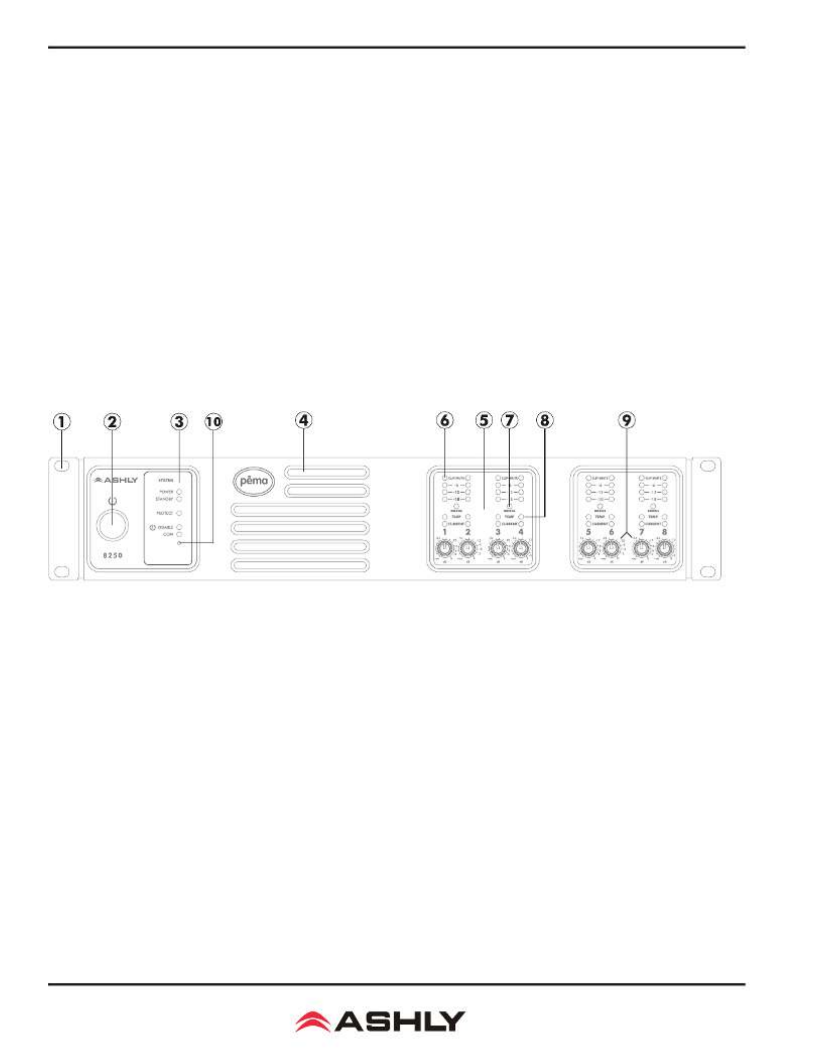
2.4 Front Panel Features
1. Mounting Holes – For rack mounting.
2. Power Switch – Switches the unit on or off. Note: The power switch can be disabled from Protea
ne Software.
3. Status LEDs – Indicate status of: Power, Standby, Protect, Power Switch Disable, and Com activity.
4. Air Inflow Vents – Cool air enters here and is vented out through the sides.
5. Channel Controls – Channel control area.
6. Signal LEDs – The lowest LED will begin to light when the output voltage reaches -18dBu below rated output. The
Clip LEDs will begin to flash when output voltage is 1/2 volt below the output power supply voltage, or the front end is clipped.
7. Bridge – This LED indicates that the channel pair is selected to BRIDGE mode from within Protea
ne software, and that
only the odd input channel level control is active.
8. Temp and Current LEDs – The Temp LED indicates that the amplifier channel has reached an excessively high oper-
ating temperature and will gradually attenuate the signal to compensate. If unable to sufficiently cool the channel, the amplifier
will eventually go into protect mode. The Current LED confirms that the amplifier output is delivered to a speaker load.
9. Channel Attenuators – These control the input signal level to the amp, and can be disabled from software.
10. Factory Reset – To reset all internal configurations (including presets and passwords) back to the original factory set-
tings, press and hold this recessed front panel momentary switch during power up until all channel LEDs sequence from bottom
to top. Upon reset completion, the LEDs will turn off and the amp will be in normal operating mode.

7
Operating Manual - Pema Protea Equipped Media Amplier
2.5 Rear Panel Features
1. Ethernet Port - This RJ-45 connector allows Ethernet control and monitoring of the amplifier using Protea
ne software.
2. Phantom Power Switch - This switch applies +15V phantom power to channel 1-4 balanced inputs. A separate switch
is used for channels 5-8.
3. TEL-PBX Switch - This switches between Mic/Line and PBX analog input for . When switched to channel one only
TEL-PBX, a 600 Ohm isolation transformer is inserted into the channel one input signal path. This transformer is designed for
limited bandwidth audio from a telephone paging system.
4. Balanced Mic/Line Input - This is used for a three wire (G, +, -) balanced analog input, and uses Euroblock connec-
tors. If an unbalanced input signal is to be connected here, wire the signal to (+), the input ground to (G), and connect (-) to (G).
5. Unbalanced Summed Mono Input - This pair of RCA jacks is used for analog line level (-10dBv) input, and sums a
stereo signal together for that input. Note: Unbalanced line level sources may reference their outputs to a different ground than
the Pema amplifier, creating the potential for ground loop hum. Always use short cable lengths for unbalanced signals, routed
away from AC, video, or data cables, and make every effort to use a common grounding point for all devices. In the event there
is still ground loop hum, isolate the unbalanced input signal by using an in-line isolation transformer.
6. Digital I/O Slot – Installation of this option allows this amplifier to be part of a CobraNet or Dante digital audio network.
7. Preamp Outputs - These Euroblock connectors provide access to post-DSP preamp signals for each channel, and are
used to drive other amplifiers or processors with the same signal that is driving the power amplifier. The preamp outputs are
pseudo-balanced, meaning they use single ended signal with balanced impedance, and can be wire balanced or unbalanced.
8. AUX Outputs - , the four AUX outputs offer additional and independent post-DSP On four channel amplifiers only
signals for driving other amplifiers or processors. AUX outputs are pseudo-balanced.
9. Euroblock Speaker Connectors - Used to connect the speakers or distributed line transformers, depending on model.
10. Remote Standby - These two contact closure pins are wired to a switch to remotely place the amp in standby.
11. Preset Recall - These four pins (using remote standby GND) can be wired to remote contact closure switches to recall
one of the first four amplifier stored presets. Preset recall function is defined within Protea
ne software.
12. Data - These four pins offer serial data control and can be wired to Ashly remote control devices such as the WR-5
or RD-8C. Ashly also offers an in-line converter called the INA-1 that allows the Data port to be used with RS-232 controllers.
13. Remote Level Control - These pins can be wired to remote 10k Ohm potentiometers such as the Ashly WR-1 for DC
level control of individual channels.
14. AC Inlet - Used for the detachable AC cord. Use only the Ashly Audio factory supplied AC cord.
15. Model Information - This sticker tells the model name, mains voltage, and mains power/current consumption.
WARNING: Do not remove or lift the mains connector ground.
Operating Manual - Pema Protea Equipped Media Amplier
8
2.6 Amplifier Protection
Ashly Pema amplifiers have the following protection circuits:
Over Current Protection - When the output current exceeds the amplifier's safe operating limits. This occurs in the
amplifier output stage.
Thermal Protection - When the internal temperature is below 40°C the fan runs at its slowest speed. Above 40°C the
speed is increased until it reaches its maximum value. If the temperature exceeds 100°C, the input on that channel is reduced.
If the temperature exceeds 110°C, the power supply is switched off.
Mains Protection – Protection within the power supply includes: In-rush Current Limitation during power up, Mains
Over Voltage Detection, and internal Mains Fuse Protection. To protect the Mains fuse against AC overcurrent due to excessive
audio output current, there is a protection scheme indicated on the amplifier front panel and in Protea
ne software which reduces
audio output level until the overcurrent condition is no longer present.
3. PROTEAne CONTROL SOFTWARE
3.1 Installing Software
Ashly Proteane software is included on a CD with each unit. Software updates may become available on the Ashly web
site. Autorun will launch the application <ProteaSystemSoftwareNE> to install the software.
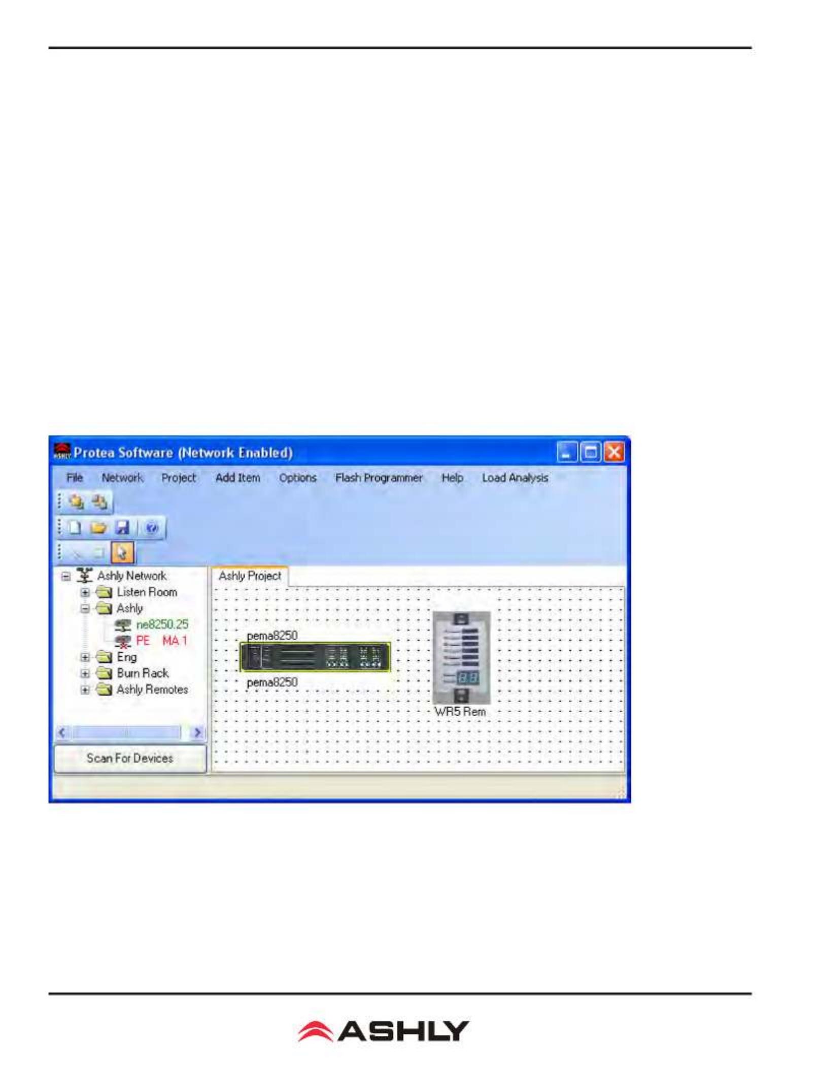
Once the software has been installed on the computer and Ethernet connections with the amplifier have been made, launch
the software. All available Ashly network enabled devices will be automatically detected and displayed in the Ashly Network
device tree on the left side of the main software startup window.
Device icons can be dragged onto the project canvas from the device tree, or placed as virtual devices in “Design Mode”.
In other words, a device icon on the canvas is not necessarily a live product. It may be a virtual device, or a device that is cur-
rently off-line. In the device tree, all currently connected and active devices are highlighted in green. Ashly devices which have
Proteane Software Main Menu, Menu Tree, and Project Canvas

9
Operating Manual - Pema Protea Equipped Media Amplier
been previously installed but are currently off-line or unavailable are highlighted in red. Individual devices can be dragged onto
the project canvas to simulate physical rack installation groups. Editing a device can be done from the device tree or an icon on
the canvas. All changes made in software are executed in real time on the device.
The software scans for active devices on start-up. The user can manually scan at any time as well with <Scan For Devices>
at the bottom of the network device tree. All devices broadcast their availability to the software when they start up.
In addition to detecting which models are currently online, any factory installed options within each amplifier are de-
tected. Dante or CobraNet are the only options available for Pema. The software control surface for each device automatically
displays available controls for installed options. Note: The user can find and verify a single physical device on the network by
right clicking over the unit’s name in the drop down menu or picture on the canvas, and then click <Identify>, which will flash
the Com LED on that unit’s face panel for two seconds.
The project canvas is used to visually represent a sound system installation, and can display any of the networked Ashly
processors, amplifiers, and remotes used in that system. The user can also place an assortment of isolated control objects such
as level faders, single LEDs, meter bars, etc, and map them to specific device functions within that project. Once a control ob-
ject is placed using <Add Items>, right click on the control object to bring up its properties. Lines, rectangles, text, even image
files can be added to create a custom virtual control screen along with individual devices and control objects and be saved in
the project. To see all available canvas tools, right click anywhere over open canvas. Checking <Design Mode> allows placed
objects to be moved around, while unchecking <Design Mode> locks all objects in place.
Once Proteane software is installed and devices identified on the network, a new project can be created and saved. A project
file represents the physical hardware installation via canvas items plus all device settings. Individual properties are edited in the
control surface window (shown below) by double clicking on the specific Pema amplifier.
Pema 8250 Main Control Surface
Operating Manual - Pema Protea Equipped Media Amplier
10
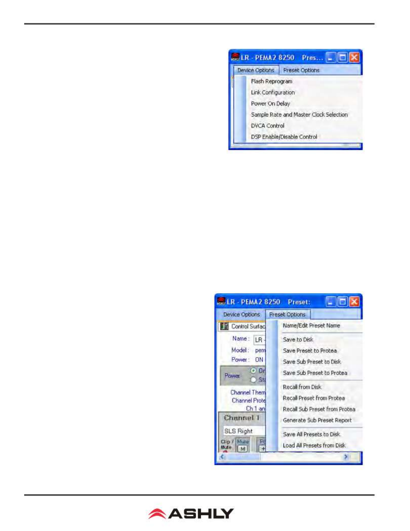
3.2 Device Options
1) Flash Reprogram Mode - The amplifier firmware can be updated
by downloading a new firmware file to the amplifier over the network. Latest
firmware updates, if available, can be found on the Ashly website. When the
amplifier is put into flash reprogram mode, the power and standby LEDs
both turn on and all audio function is suspended until flash reprogram is
completed. Note that Flash Reprogram only appears in the device options
menu when a live Pema device is connected.
2) Link Group Configuration - Link groups allow the controls for
multiple DSP functions to track each other across channels or even across
devices. For example - if two different channels or even different device
graphic equalizer blocks are linked, any change made to a control within
either of the equalizers will result in an identical change to the other. In other
words, DSP blocks may be linked within a single
device, or across multiple
devices (assuming all devices share the network).
Each device will support up to 16 Link Groups. DSP function blocks may be assigned to these groups in software. Once
assigned to a group, all LIKE functions within DSP blocks assigned to a group will track DSP parameter changes. Note that more
than one type of DSP function block can be assigned to the same link group. Each link group may be assigned a name by the
user, and also be assigned a color for easy identification. For further details about linking, see the online help in Protea
ne
software.
3) Power On Delay -
Use this feature to delay the amplifier turning on after power is provided, as well as after the amplifier is
turned back on from software standby mode*. Delay is measured in mS, with the limit at 655,350 mS, or about 11 minutes. The power
amplifier should always be the last device to power up, after other system components have turned on and stabilized. Note that the ampli-
fier must first be on for this change to take effect. *Power On Delay does not work when standby mode is activated by contact closure.
4) Sample Rate and Master Clock Source Selection - Changes to both of these settings can be made by clicking the
<Show Advanced Control> box in this menu item. Sample rate can be set to either 48kHz or 96kHz. Note that at 96kHz, the DSP
usage doubles, resulting in half the available processing power for filters, delay, limiting, etc. Also note that the Feedback Sup-
pressor cannot be used at 96kHz sample rate. Factory default settings are Auto Selection for clock source and 48kHz sample rate.
5) DVCA Control - This feature is used in conjunction with the
DSP tab gain tool called <Gain w/VCA>. Use this feature to create up
to four gain subgroups as you would on a mixing console. Any input
or output channel can be added to one or more VCA subgroups for
group gain control. While no external hardware control is allowed for
this subgroup, a level fader control object can be added to the project
canvas and linked to this named VCA level control.
6) DSP Enable/Disable - This removes from operation the input,
output, or matrix mixer DSP functions on any channel. When removed,
audio is passed directly through the stage that has been disabled.
3.3 Preset Options
1) Preset Options - The Preset Options menu in the main device
window allows setups to be named, saved to, and recalled from the
amplifier device as well as a computer on the network. Presets are a
snapshot of all current settings on a given device.
This device will store up to 31 named internal presets, each
preset storing control data for all channels and audio functions. Preset
names must be 20 characters or less. While working in Protea
ne soft-
ware, changes to an individual preset can be saved to the device using
<Save Preset To Protea>, or saved to the PC using <Save To Disk>.
Individual preset files use the extension (*.pne).
3.2 - Pema Device Options
3.3 - Pema Preset Options

11
Operating Manual - Pema Protea Equipped Media Amplier
2) Sub Presets: Instead of saving or recalling an entire preset affecting all device functions, a sub-preset affecting only
a user defined sub-set of DSP functions can be created. To create a sub-preset, first check the box labeled <Selected for sub-
presets> in any and all DSP control blocks to be associated with this sub preset, then under the preset options menu click <Save
Sub Preset to Disk> or <Save Sub Preset to Protea>.
A preset or sub preset can be loaded to the Pema amplifier by one of the following methods:
1) Use Proteane software on a PC connected to the network to recall files saved on either the PC or on the device.
2) Use contact closures to load presets 1-4 from memory by wiring switches to the rear panel contact closure connector.
3) Use an Ashly WR-5 or neWR-5 remote control.
4) Use the event scheduler
Note: A full preset recall event will overwrite any unsaved changes, so be sure the current configuration is saved before
continuing or it will be lost. The device always loads the last working settings on power-up, so as to preserve any changes if the
power is accidentally turned off prior to saving a preset. Caution: A new preset may have dramatically different settings capable
of damaging sound system components, so be careful not to recall the wrong preset while the system is on.
3.4 Device Control Tabs
The following device control tabs are available for each Pema device. The tabs include Control Surface, Security, Net-
work Properties, DSP, Input Source, Meters, Meter Dynamics, Meters AutoLeveler, Metering, Event Scheduler, and Fault Log.
3.4a Control Surface
This is the main user interface for the amplifier section
of Pema amplifier. DSP and mixing functions are managed
from within the DSP tab. The following amplifier functions
are available for monitoring or changing in the control panel:
Name - The user defined name for this specific ampli-
fier. Up to 20 characters can be used.
Model - The model of amplifier being addressed on
the network
Power - Shows power status as On, Off, or Standby
Power On/Standby - Shows power status, and allows user to set power to standby to use less power. Power standby can
also be automatically controlled by the event scheduler.
Power Switch Enable/Disable - Disables the front panel power switch
Remote Attenuator Enable/Disable - Disables "Remote Level Control" Euroblock connections on back panel
Front Panel Attenuator Enable/Disable - Disables amplifier front panel attenuator controls. Note: The software at-
tenuators will still reflect the physical position of the amplifier's front panel attenuators, even when they are disabled and not
attenuating the signal.
3.4 - Pema Device Control Tabs
3.4a - Pema Control Surface Global Functions

Operating Manual - Pema Protea Equipped Media Amplier
12
Channel Thermal - This software LED indicator becomes lit when the channel is operating at an excessive and unsus-
tainable temperature.
Channel Protect - This becomes lit when any amplifier channel is switched into protect mode, meaning one or more fault
conditions are occurring. Fault conditions include overvoltage, overcurrent, and overtemperature.
Fuse Protect - This means that the amplifier has automatically attenuated the signal in order to prevent an internal non-
user-serviceable fuse from blowing.
Rail Fault - This means that the output power supply has encountered a rail overvoltage fault.
Supply Fault - This means there is a general power supply fault. Fault conditions include fuse protect, overtemperature,
and overcurrent.
Stereo/Bridged selection - The drop-down selection box above each pair of adjacent
channels assigns stereo or bridge mode for that pair. In bridge mode, input signal is auto-
matically taken from the odd channel input and inverted, then sent to the even channel. The
even channel controls become disabled. Note that in bridge mode, the even channel software
attenuators will still reflect the physical position of the amplifier's front panel attenuators,
even though they are removed from control of bridged signal.
Channel Name - This user defined text box names the amplifier output channel. Up
to 20 characters can be used.
Clip/Mute LED - This LED shows when the amplifier output is either muted or clip-
ping. Clipping is indicated when the output level is 1/2 Volt below the output power supply
rails, and accurately tracks AC line voltage sags. All outputs become muted when the unit
is put in standby mode. This LED always shows the same status as the amplifier front panel
clip/mute LED.
Mute Button - This button mutes the output channel. Output mute can be controlled
by the event scheduler.
Polarity Button - This button inverts the polarity of the output channel signal.
Main Output Channel Fader - This controls the output attenuation. Output attenua-
tion below -40dB mutes the output.
Input Meter - This indicates the signal level in dBu as in arrives at the amplifier section.
Output Meter - This indicates the amplifier output level in dB below full rated output.
Protect LED - This individual channel protect LED indicates an overvoltage, overcur-
rent, or overtemperature fault.
Current Meter - This shows that the amplifier is delivering current to a load, and is
useful to determine if a speaker load is open or shorted.
Temperature Meter - This meter and temperature box show the current operating tem-
perature of the output devices. Excess of 100°C will trigger overtemperature protection.
Offset Link Group and Offset Faders - A group of output channels can be linked together
to attenuate the group as a whole without changing the relative levels of each channel. If a channel is assigned to one of the 16
offset link groups, a colored triangular marker appears on the left side of the main fader graticule for secondary level control
of all channels in that group. Left click and drag this marker up or down to adjust the link group level. The main level control
faders can not be linked to a group. Note that more than 40dB of cumulative channel attenuation causes the channel to mute.
In addition to the control surface offset link group attenuator control (not the main fader), most DSP functions have a link
group check box in their work window to assign a specific DSP parameter to one of 16 link groups if desired. Link groups can
be renamed by clicking on any group name and entering the new name then pressing <enter> on the keyboard.
3.4a - Pema Control Surface
Channel Functions

13
Operating Manual - Pema Protea Equipped Media Amplier
Attenuators - These two dials indicate the physi-
cal position of hardware level controls on either the amp
front panel or the remote DC level control (if present).
Note that these will display the position of attenuators
even when disabled in software.
Total Attenuation - This indicates the total amount
of attenuation being applied to the channel in dB. This is
the sum of the following attenuators: main fader, offset
link group attenuation, front panel and remote attenua-
tors (if enabled).
Note: The maximum dynamic range of the ampli-
fier is only achieved when the amplifier’s attenuators
are set to the optimal value. The amplifier’s cumulative
attenuators (as listed in the above paragraph) are located
in the signal path after all DSP processing but before the
power amplifier section. The optimal setting is deter-
mined by the maximum input signal of +20 dBu (with the
attenuators set far down), minus the input sensitivity of
+6.2 dBu (with the attenuators set at 0 dB). This equates
to approximately 14 dB of attenuation. The amplifier’s
specified dynamic range is measured with the attenuators
set to this optimal setting of 14 dB
3.4b Security Tab
Password protected user access is set up in the
security tab. User names and password are stored
within the Pema amplifier. User access is defined
by the primary user (admin or default). Available
security levels are: View only, DSP Output Channels
Access, DSP Input Channels Access, Preset Recall
Access, Audio Parameter Access, Audio Only Ac-
cess, IP only Access, and Full Access.
3.4c Network Properties Tab
In this tab, device information includes device
type, MAC address, and network connect status.
Device network configuration can be set to auto-
matic DHCP (recommended) or Manual Static IP.
Advanced Network Configuration allows the user to
bypass corporate firewalls and assign a specific port
to PEMA for remote setup and monitoring.
The user can visually identify the amplifier on
a network by clicking the "Identify Device" button,
which lights the COM LED on the amplifier's front
panel for two seconds. The amplifier's firmware revi-
sion is shown in the hardware configuration section
as well. From time to time Ashly may post updated
firmware on our website which can be downloaded
and then flash reprogrammed to the amplifier. Flash
reprogram is found in the device options menu when
connected to a live Pema device.
3.4b - Pema Security Tab
3.4c - Pema Network Properties
Termékspecifikációk
| Márka: | Ashly |
| Kategória: | Vevő |
| Modell: | PEMA 4125.70C |
Szüksége van segítségre?
Ha segítségre van szüksége Ashly PEMA 4125.70C, tegyen fel kérdést alább, és más felhasználók válaszolnak Önnek
Útmutatók Vevő Ashly

26 December 2024
26 December 2024
31 Augusztus 2024
31 Augusztus 2024
31 Augusztus 2024
31 Augusztus 2024
31 Augusztus 2024
31 Augusztus 2024
31 Augusztus 2024
31 Augusztus 2024
Útmutatók Vevő
- Vevő Phoenix Gold
- Vevő Grace Design
- Vevő Sony
- Vevő August
- Vevő Yamaha
- Vevő Nedis
- Vevő Marantz
- Vevő Philips
- Vevő Pioneer
- Vevő SilverCrest
- Vevő Garmin
- Vevő RCF
- Vevő Bosch
- Vevő Panasonic
- Vevő JVC
- Vevő StarTech.com
- Vevő Sharp
- Vevő Harman Kardon
- Vevő Nokia
- Vevő HQ
- Vevő Saramonic
- Vevő Emos
- Vevő Hifonics
- Vevő Onkyo
- Vevő Motorola
- Vevő Geemarc
- Vevő Vimar
- Vevő LogiLink
- Vevő Technics
- Vevő Roland
- Vevő JBL
- Vevő DAP-Audio
- Vevő GoGen
- Vevő AVM
- Vevő Futaba
- Vevő Insignia
- Vevő Martin Logan
- Vevő Boss
- Vevő Crestron
- Vevő Strong
- Vevő Cyrus
- Vevő VOX
- Vevő Tripp Lite
- Vevő MEE Audio
- Vevő Thomson
- Vevő Klipsch
- Vevő Hegel
- Vevő Reely
- Vevő Aiwa
- Vevő Speco Technologies
- Vevő Kenwood
- Vevő Rega
- Vevő Vivanco
- Vevő Asus
- Vevő Jabra
- Vevő Hama
- Vevő ELAC
- Vevő Zoom
- Vevő Renkforce
- Vevő Sencor
- Vevő Focusrite
- Vevő Polsen
- Vevő Bose
- Vevő Raymarine
- Vevő Mercury
- Vevő Blackstar
- Vevő Telefunken
- Vevő Sennheiser
- Vevő Tangent
- Vevő Cambridge
- Vevő Kanto
- Vevő Alpine
- Vevő Optoma
- Vevő Ibanez
- Vevő Omnitronic
- Vevő Logitech
- Vevő Amiko
- Vevő SPL
- Vevő Bresser
- Vevő Pro-Ject
- Vevő Smart
- Vevő TOA
- Vevő Dahua Technology
- Vevő SVS
- Vevő Scosche
- Vevő Hilti
- Vevő Crunch
- Vevő Denver
- Vevő Smart-AVI
- Vevő Naim
- Vevő Bush
- Vevő Power Dynamics
- Vevő Dynacord
- Vevő Trevi
- Vevő Devolo
- Vevő Memphis Audio
- Vevő DiO
- Vevő The T.amp
- Vevő DJI
- Vevő Ground Zero
- Vevő Audio-Technica
- Vevő Amazon
- Vevő Konig & Meyer
- Vevő Godox
- Vevő Cisco
- Vevő Denon
- Vevő ATen
- Vevő Electro-Voice
- Vevő JL Audio
- Vevő BOYA
- Vevő Hartke
- Vevő Auna
- Vevő Mac Audio
- Vevő Behringer
- Vevő Nexa
- Vevő Mooer
- Vevő REL Acoustics
- Vevő Chamberlain
- Vevő Chord
- Vevő Lotronic
- Vevő Bogen
- Vevő Terratec
- Vevő Shure
- Vevő Renegade
- Vevő PreSonus
- Vevő Revel
- Vevő Manhattan
- Vevő Plantronics
- Vevő Peavey
- Vevő Kogan
- Vevő Alecto
- Vevő Fontastic
- Vevő Marshall
- Vevő Velleman
- Vevő Universal Audio
- Vevő AEA
- Vevő Morel
- Vevő Russound
- Vevő Teac
- Vevő Clarion
- Vevő Blustream
- Vevő Metra
- Vevő Monacor
- Vevő MXL
- Vevő S.M.S.L
- Vevő Anthem
- Vevő McIntosh
- Vevő LD Systems
- Vevő Proel
- Vevő Jamo
- Vevő Blaupunkt
- Vevő Deaf Bonce
- Vevő NAD
- Vevő Conrad
- Vevő Thomann
- Vevő Datapath
- Vevő Sagem
- Vevő IRiver
- Vevő Samson
- Vevő Cayin
- Vevő Mackie
- Vevő Vonyx
- Vevő Alto
- Vevő Delta Dore
- Vevő Vivotek
- Vevő Infinity
- Vevő Magnat
- Vevő Bang & Olufsen
- Vevő Trust
- Vevő AKAI
- Vevő Konig
- Vevő Marmitek
- Vevő TechniSat
- Vevő Fenton
- Vevő Line 6
- Vevő Jensen
- Vevő Meliconi
- Vevő Pyle
- Vevő MuxLab
- Vevő Audioengine
- Vevő AVMATRIX
- Vevő Kemo
- Vevő Rolls
- Vevő Salora
- Vevő IFM
- Vevő Musical Fidelity
- Vevő DataVideo
- Vevő Telestar
- Vevő A-NeuVideo
- Vevő Stinger
- Vevő Atlona
- Vevő Lindy
- Vevő Audizio
- Vevő Audiotec Fischer
- Vevő Fender
- Vevő Rotel
- Vevő Hertz
- Vevő Bowers & Wilkins
- Vevő FBT
- Vevő Audiolab
- Vevő Atlas Sound
- Vevő AKG
- Vevő Marshall Electronics
- Vevő AudioControl
- Vevő Monitor Audio
- Vevő Audac
- Vevő Technical Pro
- Vevő Siig
- Vevő Yorkville
- Vevő Rockford Fosgate
- Vevő Krüger&Matz
- Vevő Salus
- Vevő Dual
- Vevő ICOM
- Vevő Gefen
- Vevő Inateck
- Vevő Warm Audio
- Vevő Wharfedale
- Vevő Kathrein
- Vevő Homematic IP
- Vevő Canton
- Vevő Yaesu
- Vevő Panduit
- Vevő HQ Power
- Vevő Vocopro
- Vevő Axis
- Vevő Optex
- Vevő Medeli
- Vevő Palmer
- Vevő Imperial
- Vevő Kicker
- Vevő FSR
- Vevő DBX
- Vevő Sangean
- Vevő Camille Bauer
- Vevő Valueline
- Vevő SureCall
- Vevő Definitive Technology
- Vevő Focal
- Vevő MB Quart
- Vevő Genie
- Vevő Legamaster
- Vevő Lectrosonics
- Vevő Hughes & Kettner
- Vevő IFi Audio
- Vevő Audix
- Vevő Vivolink
- Vevő Arcam
- Vevő FiiO
- Vevő Intelix
- Vevő Comprehensive
- Vevő Orava
- Vevő Alfatron
- Vevő Astro
- Vevő Match
- Vevő Thorens
- Vevő Majestic
- Vevő Smartwares
- Vevő Teufel
- Vevő Sogo
- Vevő Classé
- Vevő Vincent
- Vevő NuPrime
- Vevő Reloop
- Vevő CSL
- Vevő Artsound
- Vevő KanexPro
- Vevő Rupert Neve Designs
- Vevő Kramer
- Vevő Ram Audio
- Vevő ART
- Vevő BZBGear
- Vevő Ampeg
- Vevő Amplicom
- Vevő American Audio
- Vevő Hirschmann
- Vevő Audison
- Vevő Palsonic
- Vevő Caliber
- Vevő Exibel
- Vevő Vision
- Vevő Summit Audio
- Vevő Musway
- Vevő Brigmton
- Vevő Sunstech
- Vevő Elektrobock
- Vevő Avalon
- Vevő Sonance
- Vevő Oculus VR
- Vevő Redline
- Vevő Marquant
- Vevő Matrox
- Vevő Steren
- Vevő Polk
- Vevő Sandberg
- Vevő Galaxy Audio
- Vevő Denson
- Vevő Pyle Pro
- Vevő Roksan
- Vevő Valcom
- Vevő Goobay
- Vevő Hager
- Vevő Maxview
- Vevő Rocketfish
- Vevő Naxa
- Vevő Sherwood
- Vevő QTX
- Vevő Zgemma
- Vevő RDL
- Vevő Zehnder
- Vevő Mx Onda
- Vevő Fredenstein
- Vevő Metronic
- Vevő Harper
- Vevő TV STAR
- Vevő QSC
- Vevő Lanzar
- Vevő Simrad
- Vevő Humax
- Vevő Vaddio
- Vevő Gira
- Vevő Jung
- Vevő Golden Age Project
- Vevő Apart
- Vevő Pinnacle
- Vevő Eventide
- Vevő Audio Pro
- Vevő Radial Engineering
- Vevő Homecast
- Vevő Graupner
- Vevő Bluesound
- Vevő Integra
- Vevő Revox
- Vevő Engel Axil
- Vevő Comica
- Vevő Fusion
- Vevő Audient
- Vevő PAC
- Vevő Skytec
- Vevő Luxman
- Vevő JETI
- Vevő Linn
- Vevő Monoprice
- Vevő Ibiza Sound
- Vevő Exposure
- Vevő Axton
- Vevő Fostex
- Vevő MIPRO
- Vevő Solid State Logic
- Vevő Edision
- Vevő Neets
- Vevő NAV-TV
- Vevő HiFi ROSE
- Vevő OSD Audio
- Vevő Mark Levinson
- Vevő RME
- Vevő Black Lion Audio
- Vevő Soundstream
- Vevő Xoro
- Vevő DLS
- Vevő Adastra
- Vevő Block
- Vevő PSB
- Vevő Aeon Labs
- Vevő Citronic
- Vevő Formuler
- Vevő Lindell Audio
- Vevő LTC
- Vevő JB Systems
- Vevő Dreambox
- Vevő Zalman
- Vevő James
- Vevő HUMANTECHNIK
- Vevő PSSO
- Vevő Crest Audio
- Vevő Primare
- Vevő Sonifex
- Vevő Xantech
- Vevő Ferguson
- Vevő Wet Sounds
- Vevő Televés
- Vevő Manley
- Vevő Extron
- Vevő HEOS
- Vevő Madison
- Vevő Ebode
- Vevő Phonocar
- Vevő Xtrend
- Vevő Scansonic
- Vevő Helix
- Vevő Winegard
- Vevő Laney
- Vevő Devialet
- Vevő ETON
- Vevő Xsarius
- Vevő EA
- Vevő DirecTV
- Vevő Octagon
- Vevő GOgroove
- Vevő Crown
- Vevő SRS
- Vevő Avantree
- Vevő LYYT
- Vevő Antelope Audio
- Vevő CE Labs
- Vevő Pharos
- Vevő Accell
- Vevő Jolida
- Vevő Inovonics
- Vevő Ecler
- Vevő Viscount
- Vevő Ashdown Engineering
- Vevő Triax
- Vevő Synq
- Vevő Mtx Audio
- Vevő Aquatic AV
- Vevő Parasound
- Vevő DB Technologies
- Vevő Roswell
- Vevő Velodyne
- Vevő Epcom
- Vevő Sunfire
- Vevő Selfsat
- Vevő Skytronic
- Vevő CYP
- Vevő Topp Pro
- Vevő Whistler
- Vevő Astell&Kern
- Vevő Karma
- Vevő TV One
- Vevő Dimavery
- Vevő AMS Neve
- Vevő Powersoft
- Vevő LinksPoint
- Vevő Esoteric
- Vevő Markbass
- Vevő IMG Stage Line
- Vevő Wireless Solution
- Vevő Leviton
- Vevő Aurel
- Vevő ESX
- Vevő NUVO
- Vevő Phoenix Audio
- Vevő AVPro Edge
- Vevő Comtek
- Vevő Fishman
- Vevő RetroSound
- Vevő Pyramid
- Vevő LEA
- Vevő Sound Ordnance
- Vevő Canyon
- Vevő FiveO
- Vevő Planet Audio
- Vevő Phonic
- Vevő Koda
- Vevő Hotone
- Vevő Trace Elliot
- Vevő Bang Olufsen
- Vevő JTS
- Vevő AER
- Vevő Dynavox
- Vevő Modelcraft
- Vevő Klark Teknik
- Vevő Simaudio
- Vevő TIC
- Vevő Niles
- Vevő Knoll
- Vevő Creek
- Vevő Mobile Crossing
- Vevő DAP
- Vevő Krell
- Vevő GigaBlue
- Vevő ANKARO
- Vevő Bugera
- Vevő CAD Audio
- Vevő Cabasse
- Vevő Triangle
- Vevő Lab Gruppen
- Vevő Wavtech
- Vevő AmpliVox
- Vevő Audiofrog
- Vevő CyberData Systems
- Vevő WyreStorm
- Vevő Williams Sound
- Vevő Lyngdorf
- Vevő SoundTube
- Vevő WesAudio
- Vevő AudioSource
- Vevő Stewart
- Vevő Leema
- Vevő Apantac
- Vevő Axing
- Vevő Seco-Larm
- Vevő Mosconi
- Vevő Crest
- Vevő TechLogix Networx
- Vevő Audibax
- Vevő Meridian
- Vevő Quad
- Vevő BC Acoustique
- Vevő Gold Note
- Vevő IOTAVX
- Vevő Fosi Audio
- Vevő Shinybow
- Vevő Rexing
- Vevő Shanling
- Vevő Inter-M
- Vevő Sinus Live
- Vevő Soundtrack
- Vevő Canor
- Vevő C2G
- Vevő Unison Research
- Vevő Cerwin-Vega
- Vevő Universal Remote Control
- Vevő BMB
- Vevő Advance
- Vevő Cloud
- Vevő Lumantek
- Vevő Taga Harmony
- Vevő PTN-electronics
- Vevő VMV
- Vevő Black Hydra
- Vevő Bellari
- Vevő GlobalSat
- Vevő Aplic
- Vevő PureLink
- Vevő FoneStar
- Vevő Henry Engineering
- Vevő Glemm
- Vevő ButtKicker
- Vevő Atoll
- Vevő Benchmark
- Vevő Streacom
Legújabb útmutatók Vevő

9 Április 2025
9 Április 2025
5 Április 2025
5 Április 2025
2 Április 2025
2 Április 2025
2 Április 2025

31 Március 2025
31 Március 2025
30 Március 2025