Használati útmutató Alienware m16 R1 AMD
Olvassa el alább 📖 a magyar nyelvű használati útmutatót Alienware m16 R1 AMD (87 oldal) a laptop kategóriában. Ezt az útmutatót 7 ember találta hasznosnak és 2 felhasználó értékelte átlagosan 4.5 csillagra
Oldal 1/87

Alienware m16 R1 AMD
Service Manual
Regulatory Model: P124F
Regulatory Type: P124F002
April 2023
Rev. A00

Notes, cautions, and warnings
NOTE: A NOTE indicates important information that helps you make better use of your product.
CAUTION: A CAUTION indicates either potential damage to hardware or loss of data and tells you how to avoid the
problem.
WARNING: A WARNING indicates a potential for property damage, personal injury, or death.
© 2023 Dell Inc. or its subsidiaries. All rights reserved. Dell Technologies, Dell, and other trademarks are trademarks of Dell Inc. or its subsidiaries.
Other trademarks may be trademarks of their respective owners.

Contents
Chapter 1: Working inside your computer..............................................................................................6
Before working inside your computer................................................................................................................................. 6
Safety instructions.................................................................................................................................................................6
Electrostatic discharge—ESD protection............................................................................................................................ 7
ESD field service kit .............................................................................................................................................................7
Transporting sensitive components...................................................................................................................................... 8
After working inside your computer....................................................................................................................................8
Chapter 2: Removing and installing components....................................................................................9
Recommended tools.............................................................................................................................................................9
Screw list............................................................................................................................................................................... 9
Major components of Alienware m16 R1 AMD................................................................................................................. 10
Base cover........................................................................................................................................................................... 12
Removing the base cover.............................................................................................................................................. 12
Installing the base cover................................................................................................................................................14
Battery.................................................................................................................................................................................16
Lithium-ion battery precautions................................................................................................................................... 16
Removing the battery....................................................................................................................................................17
Installing the battery......................................................................................................................................................18
Battery cable.......................................................................................................................................................................19
Removing the battery cable..........................................................................................................................................19
Installing the battery cable............................................................................................................................................19
Solid-state drive.................................................................................................................................................................20
Removing the M.2 2230 solid-state drive in slot three.............................................................................................. 20
Installing the M.2 2230 solid-state drive in slot three.................................................................................................21
Removing the 2280 solid-state drive in slot one and two..........................................................................................22
Installing the 2280 solid-state drive in slot one and two............................................................................................23
Procedure to move the screw mount in SSD slot one and two...................................................................................24
Memory...............................................................................................................................................................................25
Removing the memory..................................................................................................................................................25
Installing the memory....................................................................................................................................................26
Wireless card.......................................................................................................................................................................27
Removing the wireless card.......................................................................................................................................... 27
Installing the wireless card............................................................................................................................................ 28
Fan...................................................................................................................................................................................... 29
Removing the small fan.................................................................................................................................................29
Installing the small fan...................................................................................................................................................30
Rear-I/O cover................................................................................................................................................................... 31
Removing the rear-I/O cover....................................................................................................................................... 31
Installing the rear-I/O cover........................................................................................................................................ 32
I/O board........................................................................................................................................................................... 33
Removing the I/O board.............................................................................................................................................. 33
Installing the I/O board................................................................................................................................................34
Speakers..............................................................................................................................................................................35
Removing the speakers.................................................................................................................................................35
3

Installing the speakers...................................................................................................................................................36
Power-adapter port............................................................................................................................................................37
Removing the power-adapter port.............................................................................................................................. 37
Installing the power-adapter port................................................................................................................................38
Touchpad............................................................................................................................................................................ 39
Removing the touchpad............................................................................................................................................... 39
Installing the touchpad.................................................................................................................................................40
Antennas.............................................................................................................................................................................42
Removing the antennas................................................................................................................................................ 42
Installing the antennas.................................................................................................................................................. 43
Display assembly................................................................................................................................................................ 45
Removing the display assembly....................................................................................................................................45
Installing the display assembly......................................................................................................................................46
Keyboard-controller board............................................................................................................................................... 49
Removing the keyboard-controller board.................................................................................................................. 49
Installing the keyboard-controller board.................................................................................................................... 49
System board......................................................................................................................................................................50
Removing the system board ........................................................................................................................................50
Installing the system board .......................................................................................................................................... 53
Fan and heat-sink assembly............................................................................................................................................... 56
Removing the fan and heat-sink assembly.................................................................................................................. 56
Installing the fan and heat-sink assembly.................................................................................................................... 58
Audio board....................................................................................................................................................................... 60
Removing the audio board...........................................................................................................................................60
Installing the audio board............................................................................................................................................. 61
Power button......................................................................................................................................................................62
Removing the power button........................................................................................................................................ 62
Installing the power button.......................................................................................................................................... 63
Palm-rest and keyboard assembly.....................................................................................................................................64
Removing the palm-rest and keyboard assembly....................................................................................................... 64
Installing the palm-rest and keyboard assembly......................................................................................................... 65
Chapter 3: Drivers and downloads........................................................................................................ 67
Chapter 4: System setup........................................................................................................................68
Entering BIOS setup program........................................................................................................................................... 68
Navigation keys.................................................................................................................................................................. 68
BIOS overview....................................................................................................................................................................68
Boot Sequence...................................................................................................................................................................68
System setup options......................................................................................................................................................... 69
System and setup password............................................................................................................................................... 79
Assigning a system setup password..............................................................................................................................79
Deleting or changing an existing system setup password.......................................................................................... 80
Clearing CMOS settings...............................................................................................................................................80
Clearing BIOS (System Setup) and System passwords............................................................................................... 80
Updating the BIOS............................................................................................................................................................. 81
Updating the BIOS in Windows................................................................................................................................... 81
Updating the BIOS using the USB drive in Windows................................................................................................. 81
Updating the BIOS from the F12 One Time Boot menu..............................................................................................81
4

Chapter 5: Troubleshooting...................................................................................................................83
Handling swollen Lithium-ion batteries............................................................................................................................ 83
Locate the Service Tag or Express Service Code of your Dell computer ................................................................... 83
System-diagnostic lights.................................................................................................................................................... 83
SupportAssist diagnostics.................................................................................................................................................. 84
Recovering the operating system...................................................................................................................................... 85
Backup media and recovery options................................................................................................................................. 85
Wi-Fi power cycle..............................................................................................................................................................85
Drain residual flea power (perform hard reset)................................................................................................................85
Chapter 6: Getting help and contacting Alienware............................................................................. 87
5

CAUTION: Exercise caution when handling Lithium-ion batteries in laptops. Swollen batteries should not be used and
should be replaced and disposed properly.
NOTE: The color of your computer and certain components may appear differently than shown in this document.
Electrostatic discharge—ESD protection
ESD is a major concern when you handle electronic components, especially sensitive components such as expansion cards, processors,
memory DIMMs, and system boards. Very slight charges can damage circuits in ways that may not be obvious, such as intermittent
problems or a shortened product life span. As the industry pushes for lower power requirements and increased density, ESD
protection is an increasing concern.
Due to the increased density of semiconductors used in recent Dell products, the sensitivity to static damage is now higher than in
previous Dell products. For this reason, some previously approved methods of handling parts are no longer applicable.
Two recognized types of ESD damage are catastrophic and intermittent failures.
●Catastrophic – Catastrophic failures represent approximately 20 percent of ESD-related failures. The damage causes an
immediate and complete loss of device functionality. An example of catastrophic failure is a memory DIMM that has received a
static shock and immediately generates a "No POST/No Video" symptom with a beep code emitted for missing or nonfunctional
memory.
●Intermittent – Intermittent failures represent approximately 80 percent of ESD-related failures. The high rate of intermittent
failures means that most of the time when damage occurs, it is not immediately recognizable. The DIMM receives a static shock,
but the tracing is merely weakened and does not immediately produce outward symptoms related to the damage. The weakened
trace may take weeks or months to melt, and in the meantime may cause degradation of memory integrity, intermittent memory
errors, etc.
The more difficult type of damage to recognize and troubleshoot is the intermittent (also called latent or "walking wounded") failure.
Perform the following steps to prevent ESD damage:
●Use a wired ESD wrist strap that is properly grounded. The use of wireless anti-static straps is no longer allowed; they do not
provide adequate protection. Touching the chassis before handling parts does not ensure adequate ESD protection on parts with
increased sensitivity to ESD damage.
●Handle all static-sensitive components in a static-safe area. If possible, use anti-static floor pads and workbench pads.
●When unpacking a static-sensitive component from its shipping carton, do not remove the component from the anti-static
packing material until you are ready to install the component. Before unwrapping the anti-static packaging, ensure that you
discharge static electricity from your body.
●Before transporting a static-sensitive component, place it in an anti-static container or packaging.
ESD field service kit
The unmonitored Field Service kit is the most commonly used service kit. Each Field Service kit includes three main components:
anti-static mat, wrist strap, and bonding wire.
Components of an ESD field service kit
The components of an ESD field service kit are:
●Anti-Static Mat – The anti-static mat is dissipative and parts can be placed on it during service procedures. When using an
anti-static mat, your wrist strap should be snug and the bonding wire should be connected to the mat and to any bare metal on
the system being worked on. Once deployed properly, service parts can be removed from the ESD bag and placed directly on
the mat. ESD-sensitive items are safe in your hand, on the ESD mat, in the system, or inside a bag.
●Wrist Strap and Bonding Wire – The wrist strap and bonding wire can be either directly connected between your wrist and
bare metal on the hardware if the ESD mat is not required, or connected to the anti-static mat to protect hardware that is
temporarily placed on the mat. The physical connection of the wrist strap and bonding wire between your skin, the ESD mat,
and the hardware is known as bonding. Use only Field Service kits with a wrist strap, mat, and bonding wire. Never use wireless
wrist straps. Always be aware that the internal wires of a wrist strap are prone to damage from normal wear and tear, and must be
checked regularly with a wrist strap tester in order to avoid accidental ESD hardware damage. It is recommended to test the wrist
strap and bonding wire at least once per week.
●ESD Wrist Strap Tester – The wires inside of an ESD strap are prone to damage over time. When using an unmonitored kit, it is a
best practice to regularly test the strap prior to each service call, and at a minimum, test once per week. A wrist strap tester is the
7

best method for doing this test. If you do not have your own wrist strap tester, check with your regional office to find out if they
have one. To perform the test, plug the wrist-strap's bonding-wire into the tester while it is strapped to your wrist and push the
button to test. A green LED is lit if the test is successful; a red LED is lit and an alarm sounds if the test fails.
●Insulator Elements – It is critical to keep ESD sensitive devices, such as plastic heat sink casings, away from internal parts that are
insulators and often highly charged.
●Working Environment – Before deploying the ESD Field Service kit, assess the situation at the customer location. For example,
deploying the kit for a server environment is different than for a desktop or portable environment. Servers are typically installed
in a rack within a data center; desktops or portables are typically placed on office desks or cubicles. Always look for a large open
flat work area that is free of clutter and large enough to deploy the ESD kit with additional space to accommodate the type of
system that is being repaired. The workspace should also be free of insulators that can cause an ESD event. On the work area,
insulators such as Styrofoam and other plastics should always be moved at least 12 inches or 30 centimeters away from sensitive
parts before physically handling any hardware components
●ESD Packaging – All ESD-sensitive devices must be shipped and received in static-safe packaging. Metal, static-shielded bags
are preferred. However, you should always return the damaged part using the same ESD bag and packaging that the new part
arrived in. The ESD bag should be folded over and taped shut and all the same foam packing material should be used in the
original box that the new part arrived in. ESD-sensitive devices should be removed from packaging only at an ESD-protected
work surface, and parts should never be placed on top of the ESD bag because only the inside of the bag is shielded. Always
place parts in your hand, on the ESD mat, in the system, or inside an anti-static bag.
●Transporting Sensitive Components – When transporting ESD sensitive components such as replacement parts or parts to be
returned to Dell, it is critical to place these parts in anti-static bags for safe transport.
ESD protection summary
It is recommended to use the traditional wired ESD grounding wrist strap and protective anti-static mat at all times when servicing
Dell products. In addition, it is critical to keep sensitive parts separate from all insulator parts while performing service and that they
use anti-static bags for transporting sensitive components.
Transporting sensitive components
When transporting ESD sensitive components such as replacement parts or parts to be returned to Dell, it is critical to place these
parts in anti-static bags for safe transport.
After working inside your computer
About this task
CAUTION: Leaving stray or loose screws inside your computer may severely damage your computer.
Steps
1. Replace all screws and ensure that no stray screws remain inside your computer.
2. Connect any external devices, peripherals, or cables you removed before working on your computer.
3. Replace any media cards, discs, or any other parts that you removed before working on your computer.
4. Connect your computer and all attached devices to their electrical outlets.
5. Turn on your computer.
8

Removing and installing components
NOTE: The images in this document may differ from your computer depending on the configuration you ordered.
Recommended tools
The procedures in this document may require the following tools:
●Phillips screwdriver #0
●Plastic scribe
Screw list
NOTE: When removing screws from a component, it is recommended to note the screw type, the quantity of screws, and then
place them in a screw storage box. This is to ensure that the correct number of screws and correct screw type is restored when
the component is replaced.
NOTE: Some computers have magnetic surfaces. Ensure that the screws are not left attached to such surfaces when replacing a
component.
NOTE: Screw color may vary with the configuration ordered.
Table 1. Screw list
Component Screw type Quantity Screw image
Base cover M2.5x8 (captive screw) 2
Base cover M2.5x5 6
2280 or 2230 solid-state drive
in SSD Slot one and two
M2x3.5 2
2230 solid-state drive in SSD
Slot three
M2x3.5 2
Wireless-card bracket M2x2.5 2
Small fan M2x4 3
Rear I/O cover M2x4 5
Rear I/O cover M2.5x5 2
I/O board M2x2.5 4
Battery M2x3.5 4
9

Table 1. Screw list (continued)
Component Screw type Quantity Screw image
Battery M2x4 4
Power-adapter port-bracket M2x4 2
Display-assembly hinges M2.5x5 10
Touchpad bracket M2x2.5 6
Touchpad M2x2 2
Antenna M2.5x5 4
Keyboard-controller board M2x2 2
Type-C bracket M2x2.5 2
System board M2x4 18
System board M2x2.5 2
Fan and heat-sink assembly M2x8.05 (captive) 4
Fan and heat-sink assembly M2x7.1 (captive) 4
Audio board M2x4 2
Power button bracket M2x2.5 3
Major components of Alienware m16 R1 AMD
The following image shows the major components of Alienware m16 R1 AMD.
10

1. Base cover
2. Battery
3. Memory modules
4. Wireless card
5. Wireless-card bracket
6. Keyboard-controller board
7. Power-adapter cable
8. Audio board
9. Left speaker
10. Palm-rest and keyboard assembly
11. Display assembly
12. Touchapd
13. Touchpad bracket
11

14. Antenna holder
15. Power-button bracket
16. System board
17. I/O board
18. Heat sink
19. Small fan
20.2280 solid-state drive
21. 2280 solid-state drive thermal shield
22.Rear-I/O cover
NOTE: Computers shipped with NVIDIA GeForce RTX 4080/4090, and AMD RX 7600M XT graphics card have one M.2
2230 and two M.2 2280 solid-state drive slots, whereas computers shipped with NVIDIA GeForce RTX 4050/4060/4070
graphics card have two M.2 2280 solid-state drive slots.
NOTE: Dell provides a list of components and their part numbers for the original system configuration purchased. These parts
are available according to warranty coverages purchased by the customer. Contact your Dell sales representative for purchase
options.
Base cover
Removing the base cover
Prerequisites
1. Follow the procedure in Before working inside your computer.
About this task
The following image(s) indicate the location of the base cover and provides a visual representation of the removal procedure.
12

13
Steps
1. Remove the six screws (M2.5x5) that secure the base cover to the palm-rest and keyboard assembly.
2. Loosen the two captive screws (M2.5x8) that secure the base cover to the palm-rest and keyboard assembly.
3. Using a plastic scribe, pry the base cover from the bottom left and continue to work on the sides to open the base cover.
4. Slide and lift the base cover off the palm-rest and keyboard assembly.
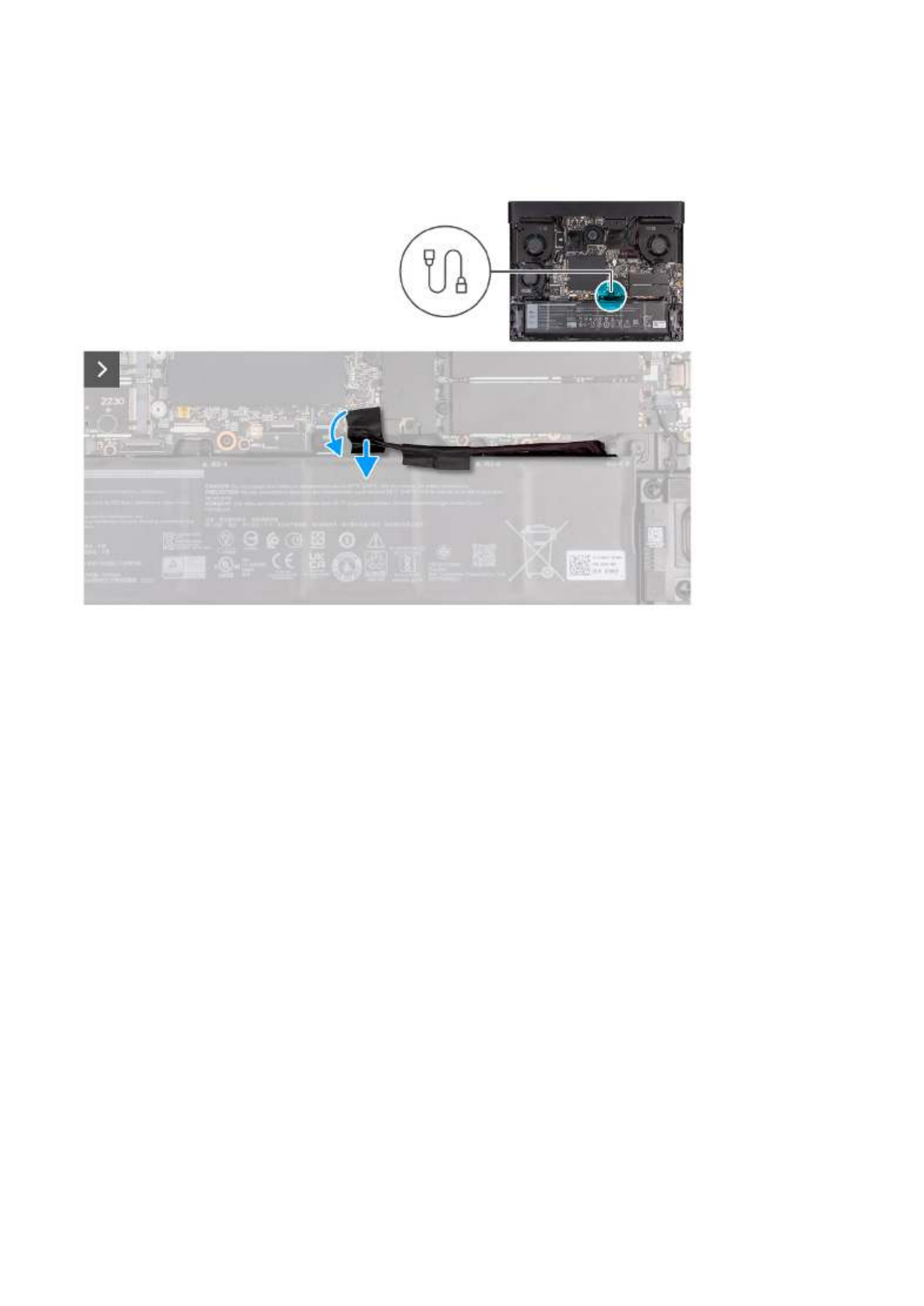
5. Peel the tape that secures the battery cable to the battery.
6. Disconnect the battery cable from the system board.
Installing the base cover
Prerequisites
If you are replacing a component, remove the existing component before performing the installation process.
About this task
The following image(s) indicate the location of the base cover and provides a visual representation of the installation procedure.
14

Steps
1. Connect the battery cable to the system board.
2. Adhere the tape that secures the battery cable to the battery.
3. Slide the tabs on the top of the base cover under the I/O-cover and snap the base cover to the palm-rest and keyboard
assembly.
15

4. Tighten the two captive screws (M2.5x8) on the base cover that secure the base cover to the palm-rest and keyboard assembly.
5. Replace the six screws (M2.5x5) that secure the base cover to the palm-rest and keyboard assembly.
Next steps
1. Follow the procedure in .
After working inside your computer
Battery
Lithium-ion battery precautions
CAUTION:
●Exercise caution when handling Lithium-ion batteries.
●Discharge the battery completely before removing it. Disconnect the AC power adapter from the system and operate
the computer solely on battery power—the battery is fully discharged when the computer no longer turns on when the
power button is pressed.
●Do not crush, drop, mutilate, or penetrate the battery with foreign objects.
●Do not expose the battery to high temperatures, or disassemble battery packs and cells.
16

●Do not apply pressure to the surface of the battery.
●Do not bend the battery.
●Do not use tools of any kind to pry on or against the battery.
●Ensure any screws during the servicing of this product are not lost or misplaced, to prevent accidental puncture or
damage to the battery and other system components.
●If the battery gets stuck inside your computer as a result of swelling, do not try to release it as puncturing, bending, or
crushing a lithium-ion battery can be dangerous. In such an instance, contact Dell technical support for assistance. See
www.dell.com/contactdell.
●Always purchase genuine batteries from or authorized Dell partners and resellers.www.dell.com
●Swollen batteries should not be used and should be replaced and disposed properly. For guidelines on how to handle
and replace swollen Lithium-ion batteries, see .
Handling swollen Lithium-ion batteries
Removing the battery
Prerequisites
1. Follow the procedure in Before working inside your computer.
2. Remove the base cover.
About this task
NOTE: This computer is designed without an RTC coin cell-battery. After a service incident where the computer battery is
disconnected, when the battery is fully discharged, or when the computer is reassembled and turned on, an RTC reset cycle will
occur. When an RTC Reset cycle occurs, the computer turns on and off three times. An "Invalid Configuration" error message
is displayed prompting you to enter the BIOS and configure the date and time. The computer starts functioning normally after
setting the date and time.
NOTE: Removing the battery resets the BIOS setup program's settings to default. It is recommended that you note the BIOS
setup program's settings before removing the battery.
The following image(s) indicate the location of the battery and provides a visual representation of the removal procedure.
17
Termékspecifikációk
| Márka: | Alienware |
| Kategória: | laptop |
| Modell: | m16 R1 AMD |
Szüksége van segítségre?
Ha segítségre van szüksége Alienware m16 R1 AMD, tegyen fel kérdést alább, és más felhasználók válaszolnak Önnek
Útmutatók laptop Alienware

12 Január 2025
7 Január 2025
30 December 2025
30 December 2025
30 December 2025
18 Augusztus 2024
18 Augusztus 2024
18 Augusztus 2024
14 Augusztus 2024
13 Augusztus 2024
Útmutatók laptop
- laptop Samsung
- laptop Sony
- laptop Fujitsu
- laptop Acer
- laptop LG
- laptop Oregon Scientific
- laptop Panasonic
- laptop Lenovo
- laptop Toshiba
- laptop HP
- laptop Hyundai
- laptop Apple
- laptop Fellowes
- laptop Medion
- laptop Zebra
- laptop Xiaomi
- laptop Dell
- laptop Gigabyte
- laptop Tripp Lite
- laptop Prixton
- laptop Thomson
- laptop Huawei
- laptop Microsoft
- laptop Asus
- laptop PEAQ
- laptop Haier
- laptop Viewsonic
- laptop Denver
- laptop MSI
- laptop Honor
- laptop SPC
- laptop ADATA
- laptop Kogan
- laptop Razer
- laptop Jay-Tech
- laptop Pyle
- laptop Schneider
- laptop Micromax
- laptop NEC
- laptop Siig
- laptop GoClever
- laptop Getac
- laptop ECS
- laptop Packard Bell
- laptop TechBite
- laptop Airis
- laptop Lexibook
- laptop Emachines
- laptop Trekstor
- laptop Hähnel
- laptop Sylvania
- laptop Coby
- laptop Evga
- laptop Ricatech
- laptop Mpman
- laptop Vizio
- laptop Targa
- laptop Ematic
- laptop Hannspree
- laptop XPG
- laptop Inovia
- laptop Odys
- laptop Ergotron
- laptop Ibm
- laptop Atdec
- laptop Compaq
- laptop Hercules
- laptop Vulcan
- laptop System76
- laptop General Dynamics Itronix
- laptop CTL
- laptop Everex
- laptop Olidata
- laptop Dynabook
- laptop Hamilton Buhl
- laptop AORUS
- laptop Humanscale
- laptop Aplic
- laptop Schenker
Legújabb útmutatók laptop
3 Április 2025

28 Március 2025

28 Március 2025
27 Március 2025

20 Március 2025

18 Március 2025
16 Január 2025
13 Január 2025

13 Január 2025
13 Január 2025