Használati útmutató Alienware Aurora R4
Olvassa el alább 📖 a magyar nyelvű használati útmutatót Alienware Aurora R4 (162 oldal) a Asztali kategóriában. Ezt az útmutatót 5 ember találta hasznosnak és 2 felhasználó értékelte átlagosan 4.5 csillagra
Oldal 1/162

w w w . d e l l . c o m | s u p p o r t . d e l l . c o m / m a n u a l s
Alienware Aurora-R4
Owner’s Manual
Regulatory model: D01M
Regulatory type: D01M004

Notes, Cautions, and Warnings
NOTE: A NOTE indicates important information that helps you make better
use of your product.
CAUTION: A CAUTION indicates either potential damage to hardware or
loss of data, and tells you how to avoid the problem.
WARNING: A WARNING indicates a potential for property damage,
personal injury, or death.
Information in this document is subject to change without notice.
© 2011 Dell Inc. All rights reserved.
Reproduction of these materials in any manner whatsoever without the written permission of Dell Inc.
is strictly forbidden.
Trademarks used in this text: Dell™ and the DELL logo are trademarks of Dell Inc. Alienware
® is a
registered trademark of Alienware Corporation. Microsoft®, Windows®, and the Windows start button
logo are either trademarks or registered trademarks of Microsoft Corporation in the United States and/
or other countries.
Other trademarks and trade names may be used in this document to refer to either the entities claiming
the marks and names or their products. Dell Inc. disclaims any proprietary interest in trademarks and
trade names other than its own.
2011 - 12 Rev. A00

Contents 3
Contents
1 Before You Begin . . . . . . . . . . . . . . . . . . . 13
Turn Off Your Computer and Connected Devices . . . . 13
Safety Instructions . . . . . . . . . . . . . . . . . . . . 13
Recommended Tools. . . . . . . . . . . . . . . . . . . 14
2 After Working Inside Your Computer. . . . 15
3 Technical Overview . . . . . . . . . . . . . . . . . 17
Front View of Your Computer . . . . . . . . . . . . . . 17
Back View of Your Computer . . . . . . . . . . . . . . 18
Inside View of Your Computer . . . . . . . . . . . . . . 19
System-Board Components . . . . . . . . . . . . . . . 20
Master I/O Board Components . . . . . . . . . . . . . 21
Top Lighting-Board Components . . . . . . . . . . . . 23
4 Left Side-Panel . . . . . . . . . . . . . . . . . . . . 25
Removing the Left Side-Panel . . . . . . . . . . . . . . 25
Replacing the Left Side-Panel. . . . . . . . . . . . . . 27

Contents 5
Postrequisites . . . . . . . . . . . . . . . . . . . . . . 44
9 PCI Shroud . . . . . . . . . . . . . . . . . . . . . . . . 45
Prerequisites. . . . . . . . . . . . . . . . . . . . . . . 45
Opening the PCI Shroud . . . . . . . . . . . . . . . . . 45
Closing the PCI Shroud . . . . . . . . . . . . . . . . . 46
Postrequisites . . . . . . . . . . . . . . . . . . . . . . 46
10 Drive-Bay Shroud . . . . . . . . . . . . . . . . . . 47
Prerequisites. . . . . . . . . . . . . . . . . . . . . . . 47
Removing the Drive-Bay Shroud . . . . . . . . . . . . 47
Replacing the Drive-Bay Shroud . . . . . . . . . . . . 48
Postrequisites . . . . . . . . . . . . . . . . . . . . . . 48
11 PCI-Express p5-x1 Card . . . . . . . . . . . . . . . . 49
Prerequisites. . . . . . . . . . . . . . . . . . . . . . . 49
Removing the PCI-Express p5-x1 Card . . . . . . . . . . . 49
Replacing the PCI-Express p5-x1 Card. . . . . . . . . . . 50
Postrequisites . . . . . . . . . . . . . . . . . . . . . . 51
12 PCI-Fan . . . . . . . . . . . . . . . . . . . . . . . . . . 53
Prerequisites. . . . . . . . . . . . . . . . . . . . . . . 53

6Contents
Removing the PCI-Fan . . . . . . . . . . . . . . . . . . 53
Replacing the PCI-Fan . . . . . . . . . . . . . . . . . . 54
Postrequisites . . . . . . . . . . . . . . . . . . . . . . 55
13 Graphics Card . . . . . . . . . . . . . . . . . . . . 57
Prerequisites . . . . . . . . . . . . . . . . . . . . . . . 57
Removing the Graphics Card. . . . . . . . . . . . . . . 57
Replacing the Graphics Card . . . . . . . . . . . . . . 58
Postrequisites . . . . . . . . . . . . . . . . . . . . . . 59
Installing Dual Graphic Cards . . . . . . . . . . . . . . 59
Connect the Display. . . . . . . . . . . . . . . . . 61
14 Memory Module(s). . . . . . . . . . . . . . . . . 63
Prerequisites . . . . . . . . . . . . . . . . . . . . . . . 63
Removing Memory Module(s) . . . . . . . . . . . . . . 63
Replacing Memory Module(s) . . . . . . . . . . . . . . 64
Postrequisites . . . . . . . . . . . . . . . . . . . . . . 66
15 Memory Fan . . . . . . . . . . . . . . . . . . . . . . 67
Prerequisites . . . . . . . . . . . . . . . . . . . . . . . 67
Removing the Memory Fan. . . . . . . . . . . . . . . . 67
Replacing the Memory Fan . . . . . . . . . . . . . . . 68

8Contents
Removing the Coin-Cell Battery . . . . . . . . . . . . . 89
Replacing the Coin-Cell Battery . . . . . . . . . . . . . 90
Postrequisites . . . . . . . . . . . . . . . . . . . . . . 90
20 Theater-Lighting Batteries
(ALX Chassis Only) . . . . . . . . . . . . . . . . . 93
Prerequisites . . . . . . . . . . . . . . . . . . . . . . . 93
Removing the Theater-Lighting Batteries . . . . . . . . 93
Replacing the Theater-Lighting Batteries . . . . . . . . 94
Postrequisites . . . . . . . . . . . . . . . . . . . . . . 94
21 System-Board Assembly . . . . . . . . . . . . 95
Prerequisites . . . . . . . . . . . . . . . . . . . . . . . 95
Removing the System-Board Assembly . . . . . . . . . 95
Replacing the System-Board Assembly . . . . . . . . . 96
Postrequisites . . . . . . . . . . . . . . . . . . . . . . 97
Entering the Service Tag in BIOS . . . . . . . . . . . . 97
22 Master I/O Board . . . . . . . . . . . . . . . . . . 99
Prerequisites . . . . . . . . . . . . . . . . . . . . . . . 99
Removing the Master I/O Board . . . . . . . . . . . . . 99
Replacing the Master I/O Board . . . . . . . . . . . . 100

Contents 9
Postrequisites . . . . . . . . . . . . . . . . . . . . . . 100
23 Top Lighting-Board . . . . . . . . . . . . . . . . 103
Prerequisites. . . . . . . . . . . . . . . . . . . . . . . 103
Removing the Top Lighting-Board . . . . . . . . . . . . 103
Replacing the Top Lighting-Board. . . . . . . . . . . . 104
Postrequisites . . . . . . . . . . . . . . . . . . . . . . 104
24 Right-Side Top Panel . . . . . . . . . . . . . . . 107
Prerequisites. . . . . . . . . . . . . . . . . . . . . . . 107
Removing the Right-Side Top Panel . . . . . . . . . . . 107
Replacing the Right-Side Top Panel. . . . . . . . . . . 110
Postrequisites . . . . . . . . . . . . . . . . . . . . . . 111
25 Right-Side Middle Panel . . . . . . . . . . . . 113
Prerequisites. . . . . . . . . . . . . . . . . . . . . . . 113
Removing the Right-Side Middle Panel . . . . . . . . . 113
Replacing the Right-Side Middle Panel. . . . . . . . . 114
Postrequisites . . . . . . . . . . . . . . . . . . . . . . 115
26 Right Lighting-Board . . . . . . . . . . . . . . . 117
Prerequisites. . . . . . . . . . . . . . . . . . . . . . . 117

10 Contents
Removing the Right Lighting-Board . . . . . . . . . . 117
Replacing the Right Lighting-Board . . . . . . . . . . 118
Postrequisites . . . . . . . . . . . . . . . . . . . . . 119
27 Right-Side Bottom Panel . . . . . . . . . . . . 121
Prerequisites . . . . . . . . . . . . . . . . . . . . . . 121
Removing the Right-Side Bottom Panel . . . . . . . . 121
Replacing the Right-Side Bottom Panel. . . . . . . . 123
Postrequisites . . . . . . . . . . . . . . . . . . . . . 124
28 Top Vent . . . . . . . . . . . . . . . . . . . . . . . . . 125
Prerequisites . . . . . . . . . . . . . . . . . . . . . . 125
Removing the Top Vent . . . . . . . . . . . . . . . . . 125
Replacing the Top Vent. . . . . . . . . . . . . . . . . 127
Postrequisites . . . . . . . . . . . . . . . . . . . . . 128
29 Front Bezel . . . . . . . . . . . . . . . . . . . . . . . 129
Prerequisites . . . . . . . . . . . . . . . . . . . . . . 129
Removing the Front Bezel . . . . . . . . . . . . . . . 129
Replacing the Front Bezel . . . . . . . . . . . . . . . 131
Postrequisites . . . . . . . . . . . . . . . . . . . . . 132

Contents 11
30 Back Bezel . . . . . . . . . . . . . . . . . . . . . . . 133
Prerequisites. . . . . . . . . . . . . . . . . . . . . . . 133
Removing the Back Bezel . . . . . . . . . . . . . . . . 133
Replacing the Back Bezel . . . . . . . . . . . . . . . . 136
Postrequisites . . . . . . . . . . . . . . . . . . . . . . 136
31 WiFi/Bluetooth Assembly . . . . . . . . . . . 137
Prerequisites. . . . . . . . . . . . . . . . . . . . . . . 137
Removing the WiFi/Bluetooth Card . . . . . . . . . . . 137
Replacing the WiFi/Bluetooth Card . . . . . . . . . . . 138
Postrequisites . . . . . . . . . . . . . . . . . . . . . . 138
32 Top I/O Panel . . . . . . . . . . . . . . . . . . . . . 141
Prerequisites. . . . . . . . . . . . . . . . . . . . . . . 141
Removing the Top I/O Panel . . . . . . . . . . . . . . . 141
Replacing the Top I/O Panel . . . . . . . . . . . . . . . 142
Postrequisites . . . . . . . . . . . . . . . . . . . . . . 143
33 System Setup . . . . . . . . . . . . . . . . . . . . . 145
Overview . . . . . . . . . . . . . . . . . . . . . . . . . 145
Entering System Setup . . . . . . . . . . . . . . . . . . 145
System Setup Screens . . . . . . . . . . . . . . . 145
System Setup Options . . . . . . . . . . . . . . . 146

12 Contents
Boot Sequence . . . . . . . . . . . . . . . . . . 152
Clearing Forgotten Passwords. . . . . . . . . . . . . 154
Password: . . . . . . . . . . . . . . . . . . . . . 155
. . . . . . . . . . . . . . . . . . . . . . . . . . 155
Clearing CMOS Passwords . . . . . . . . . . . . . . 156
CMOS:. . . . . . . . . . . . . . . . . . . . . . . 156
34 Flashing the BIOS . . . . . . . . . . . . . . . . . 159
35 Specifications . . . . . . . . . . . . . . . . . . . . 161

Before you Begin 13
3
Before You Begin
Turn Off Your Computer and Connected Devices
CAUTION: To avoid losing data, save and close all open files and exit all open
programs before you turn off your computer.
1
Save and close all open files and exit all open programs.
2
Click
Start
and click
Shut Down
.
Microsoft Windows shuts down and then the computer turns off.
NOTE: If you are using a different operating system, see the documentation of
your operating system for shut-down instructions.
3
Disconnect your computer and all attached devices from their electrical
outlets.
4
Disconnect all telephone cables, network cables, and attached devices
from your computer.
5
Press and hold the power button, while the computer is unplugged, to
ground the system board.
Safety Instructions
Use the following safety guidelines to protect your computer from potential
damage and ensure your personal safety.
WARNING: Before working inside your computer, read the safety information
that shipped with your computer. For additional safety best practices information,
see the Regulatory Compliance Homepage at dell.com/regulatory_compliance.
CAUTION: To avoid damaging the computer, ensure that the work surface is flat
and clean.
CAUTION: To avoid damaging the components and cards, handle them by their
edges and avoid touching pins and contacts.
WARNING: Disconnect all power sources before opening the computer cover or
panels. After you finish working inside the computer, replace all covers, panels,
and screws before connecting to the power source.

14 Before you Begin
CAUTION: Only a certified service technician is authorized to remove the
computer cover and access any of the components inside the computer. See the
safety instructions for complete information about safety precautions, working
inside your computer, and protecting against electrostatic discharge.
CAUTION: Before touching anything inside your computer, ground yourself by
touching an unpainted metal surface, such as the metal at the back of the
computer. While you work, periodically touch an unpainted metal surface to
dissipate static electricity, which could harm internal components.
CAUTION: When you disconnect a cable, pull on its connector or on its pull-tab,
not on the cable itself. Some cables have connectors with locking tabs or
thumb-screws that you connecting the cable. When must disengage before dis
disconnecting cables, keep them evenly aligned to avoid bending any connector
pins. When connecting cables, ensure that the connectors and ports are correctly
oriented and aligned.
CAUTION: To disconnect a network cable, first unplug the cable from your
computer and then unplug the cable from the network device.
Recommended Tools
The procedures in this document may require the following tools:
• Small Phillips screwdriver
• Hex nut driver
• Flash BIOS executable update program available at
support.dell.com

After Working Inside Your Computer 15
4
After Working Inside Your Computer
After you complete replacement procedures, ensure the following:
• Replace all screws and ensure no stray screws remain inside your computer
• Connect any external devices, cables, cards, and any other part you
removed before working on your computer
• Connect your computer and all attached devices to their electrical outlets
CAUTION: Before turning on your computer, replace all screws and ensure that
no stray screws remain in the computer. Failure to do so may damage your
computer.
• Turn on your computer.

16 Before you Begin

Technical Overview 17
1
Technical Overview
WARNING: Before working inside your computer, read the safety information
that shipped with your computer and follow the steps in "Before You Begin" on
page 13. For additional safety best practices information, see the Regulatory
Compliance Homepage at dell.com/regulatory_compliance.
Front View of Your Computer
7
1
8
11
910
2
3
4
5
6
18 Technical Overview
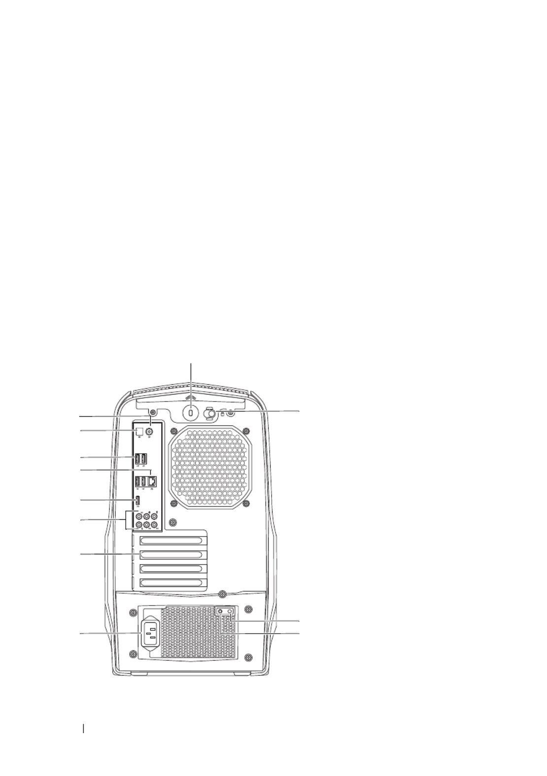
Back View of Your Computer
1 2AlienHead/drive-panel open button optical drive
3 4optical-drive eject button optical-drive bay
5 media-card reader/optical-drive bay 6 drive panel (open)
7 8headphone connector microphone connector
9 USB 3.0 connector 10 power button
11 USB 2.0 connectors (2)
1
2
3
4
5
6
7
8 9
10
11
12
Technical Overview 19
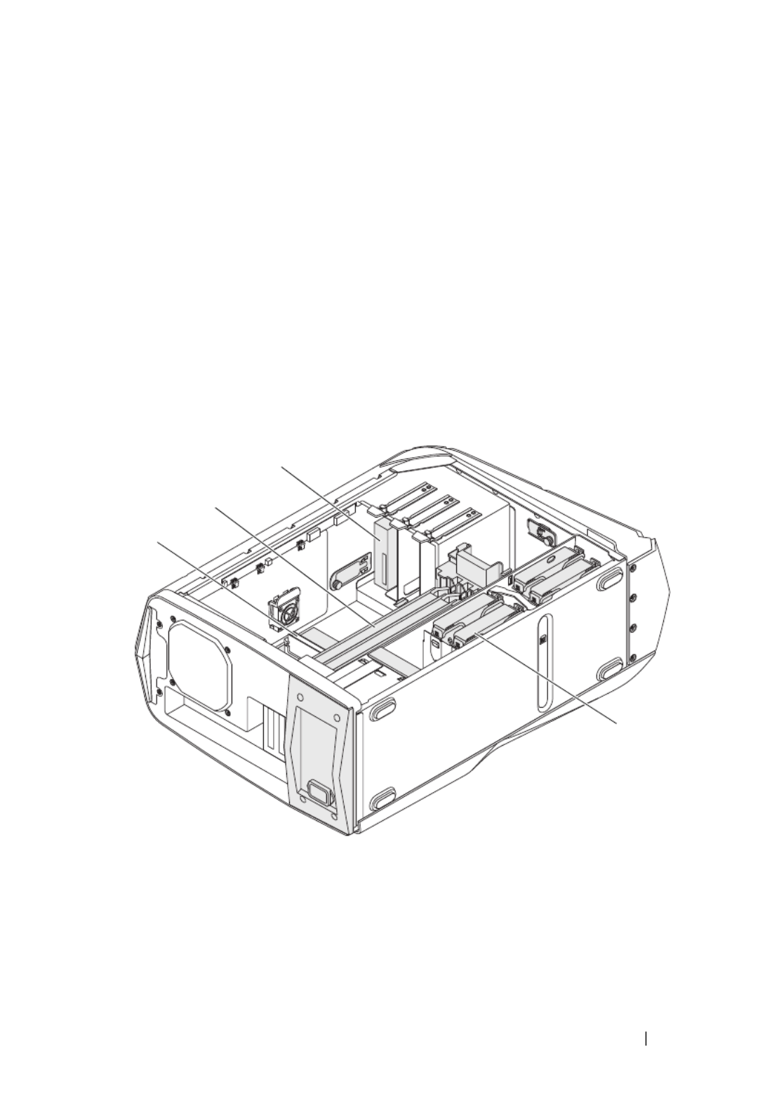
Inside View of Your Computer
1 coaxial S/PDIF connector 2 optical S/PDIF connector
3 4USB 2.0 connectors (4) network connector and network
lights
5 6USB 3.0 connector audio connectors
7 8expansion-card slots power connector
9 power-supply diagnostics button 10 power-supply diagnostics light
11 security-cable slot latch 12 security-cable slot
1 2memory module(s) PCI-Express card(s)
3 4optical drive(s) hard-drive(s)
1
2
3
4
20 Technical Overview
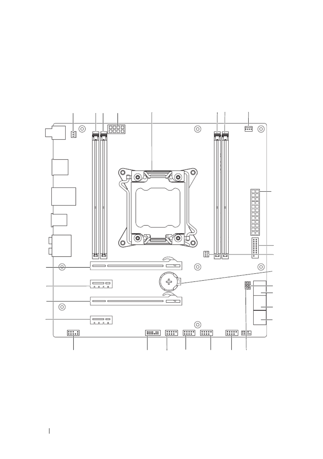
System-Board Components
15
9
14
15
181920212223
24
25
26
27 12
6
2 3 4 7 8
10
13
16
11
17

Technical Overview 21
Master I/O Board Components
NOTE: The location of the connectors may vary based on the selections you made
at the time of purchase.
1 heat-sink fan connector
(SYS_FAN1)
2 memory-module connector
(DIMM1)
3 memory-module connector
(DIMM2)
4 processor power connector (PWR2)
5 processor socket (CPU1) 6 memory-module connector
(DIMM4)
7 memory-module connector
(DIMM3)
8 processor fan connector
(CPU_FAN)
9 main power connector (PWR1) 10 front USB connector (FUSB3_0)
11 heat-sink fan connector
(SYS_FAN2)
12 battery socket (BAT1)
13 CMOS jumper (CLEAR_CMOS) 14 serial ATA drive connectors
(SATA1_2)
15 serial ATA drive connectors
(SATA3_4)
16 serial ATA drive connectors
(SATA5_6)
17 password jumper (PASSWORD) 18 front panel connector
(FRONT_PANEL)
19 USB connector (USB1) 20 USB connector (USB2)
21 USB connector (USB3) 22 Low pin count debug header (LPC)
23 front audio connector
(FRONT_AUDIO)
24 PCI-Express p21-x1 connector (SLOT4)
25 PCI-Express x16 connector
(SLOT3)
26 PCI-Express p21-x1 connector (SLOT2)
27 PCI-Express x16 connector (SLOT1)

22 Technical Overview
1 FlexBay connector (FLEXBAY) 2 drive-bay shroud battery connector
(FRONT_BEZEL)
3 4AlienHead connector (HEAD1) PCI-fan connector (FAN_PCI)
5 left side-panel contact board
connector (SIDE_L)
6 WiFi/Bluetooth connector
(BLUETOOTH)
7 power-LED board connector
(BLINK)
8 wireless connector (WIRELESS)
9
10
12
11
1 2 3 4 5 6 7
8
131415
16
18
21
20
19
17

Technical Overview 23
Top Lighting-Board Components
9 hard-drive LED connector
(HDD_LED1)
10 hard-drive LED connector
(HDD_LED2)
11 USB connector (MB_USB) 12 main-power connector (PWR1)
13 system-board lighting (MB_MIO) 14 hard-drive fan connector
(FAN_HDD)
15 right side-panel connector
(SIDE_R)
16 ODD sensors (ODD_SW)
17 ODD LED connector
(ODD_LED)
18 front-default connector
(FACTORY_DEFAULT)
19 Debug connector (DEBUG) 20 graphics-temperature sensor
connector (GFX_TEMP)
21 graphics-pump connector (GFX_PUMP)
1 System fan connector (SYS FAN) 2 CPU fan connector (CPU FAN)
3 Temperature sensor connector
(TEMP SENSOR)
4 Memory fan connector
(MEM FAN)
5 CPU pump connector (CPU PUMP)
1 2 3 4 5

24 Technical Overview
Left Side-Panel 25
2
Left Side-Panel
WARNING: Before working inside your computer, read the safety information
that shipped with your computer and follow the steps in "Before You Begin" on
page 13. For additional safety best practices information, see the Regulatory
Compliance Homepage at dell.com/regulatory_compliance.
CAUTION: Ensure that sufficient space exists to support the computer with the
computer cover removed—at least 30 cm (1 ft.) of desk top space.
Removing the Left Side-Panel
NOTE: Ensure that you remove the security cable from the security cable slot (if
applicable).
1
Slide the security-cable slot latch to the unlocked position.
2
Lift the release panel to open the left side-panel.
3
Pull and lift the left side-panel away from the chassis.
NOTE: Theater lighting (available only in ALX chassis) turns on automatically when
the left side-panel is removed.

26 Left Side-Panel
1 release panel 2 security-cable slot
3 security-cable slot latch 4 left side-panel
1
2
3
4

30 Hard Drive(s)
Replacing the Hard Drive(s)
1
Slide the hard drive into the hard-drive cage until the release tabs snap
into place.
Postrequisites
1
Replace the left side-panel. See "Replacing the Left Side-Panel" on
page 27.
1 release tabs (2) 2 hard-drive
3 hard-drive cage
1
2
3

32 Hard Drive(s)

Hard-Drive Fan Assembly 33
4
Hard-Drive Fan Assembly
WARNING: Before working inside your computer, read the safety information
that shipped with your computer and follow the steps in "Before You Begin" on
page 13. For additional safety best practices information, see the Regulatory
Compliance Homepage at dell.com/regulatory_compliance.
WARNING: The heat sink may be very hot during normal operation. Provide
sufficient time for the heat-sink to cool before you touch it.
Prerequisites
1
Remove the left side-panel. See "Removing the Left Side-Panel" on
page 25.
Removing the Hard-Drive Fan Assembly
1
Open the PCI shroud. See "Opening the PCI Shroud" on page 45.
2
Remove the drive-bay shroud. See "Removing the Drive-Bay Shroud" on
page 47.
NOTE: Be careful not to damage the hard-drive fan cable while lifting the
hard-drive fan assembly.
3
Carefully slide the hard-drive fan assembly out of the hard-drive fan
assembly bay.
4
Note the routing of the hard-drive fan cable and then disconnect the hard-
drive fan cable from the FAN_HDD connector on the master I/O board.
5
Lift the hard-drive fan assembly out of the chassis.
34 Hard-Drive Fan Assembly
Replacing the Hard-Drive Fan Assembly
1
Slide the hard-drive fan assembly into the hard-drive fan assembly bay.
2
Route the cable through the slot in the hard-drive bay and then connect
the hard-drive fan assembly cable to the FAN_HDD connector on the
master I/O board.
3
Replace the drive-bay shroud. See "Replacing the Drive-Bay Shroud" on
page 48.
4
Close the PCI shroud. See "Closing the PCI Shroud" on page 46.
1 hard-drive fan cable 2 hard-drive fan assembly
1
2

Hard-Drive Fan Assembly 35
Postrequisites
1
Replace the left side-panel. See "Replacing the Left Side-Panel" on
page 27.
2
Follow the steps in "After Working Inside Your Computer" on page 15.

36 Hard-Drive Fan Assembly

Optical Drive(s) 37
5
Optical Drive(s)
WARNING: Before working inside your computer, read the safety information
that shipped with your computer and follow the steps in "Before You Begin" on
page 13. For additional safety best practices information, see the Regulatory
Compliance Homepage at dell.com/regulatory_compliance.
Prerequisites
1
Remove the left side-panel. See "Removing the Left Side-Panel" on
page 25.
Removing the Optical Drive(s)
1
Press the AlienHead on the front of your computer to lower the drive
panel.
2
Disconnect the data cable and power cable from the optical drive.
3
Lift the securing tab, and holding the tab in place, push and slide the
optical drive out through the front of the computer.

38 Optical Drive(s)
Replacing the Optical Drive(s)
1
Lift and hold the securing tab, and then slide the optical drive through the
front of the computer until the securing tab snaps into place.
2
Connect the power cable and the data cable to the optical drive.
3
Lift the drive panel towards the top of your computer until it snaps into
place.
Postrequisites
1
Replace the left side-panel. See "Replacing the Left Side-Panel" on
page 27.
1 power cable 2 data cable
3 securing tab 4 optical drive
1
2
34

Optical Drive(s) 39
2
Follow the steps in "After Working Inside Your Computer" on page 15.

40 Optical Drive(s)

Media-Card Reader 41
6
Media-Card Reader
WARNING: Before working inside your computer, read the safety information
that shipped with your computer and follow the steps in "Before You Begin" on
page 13. For additional safety best practices information, see the Regulatory
Compliance Homepage at dell.com/regulatory_compliance.
Prerequisites
1
Remove the left side-panel. See "Removing the Left Side-Panel" on
page 25.
Removing the Media-Card Reader
1
Press the AlienHead on the front of your computer to lower the drive
panel.
2
Open the PCI shroud. See "Opening the PCI Shroud" on page 45.
3
Disconnect the FlexBay USB cable from the FLEXBAY connector on the
master I/O board. For more information on the location of the connector,
see "Master I/O Board Components" on page 21.
4
Lift and hold the securing tab and then push the FlexBay dock to slide it
out through the front of the computer.

42 Media-Card Reader
5
Remove the screws that secure the media-card reader to the FlexBay dock.
6
Slide the media-card reader out of the FlexBay dock.
1 FlexBay USB cable 2 securing tab
3 FlexBay dock 4 Master I/O board
5 FlexBay USB cable-connector
1
2
3
5
4

Media-Card Reader
Replacing the Media-Card Reader
1
Slide the media-card reader into the FlexBay dock.
2
Replace the screws that secure the media-card reader to the FlexBay dock.
3
Lift the securing tab and slide the FlexBay dock through the front of the
computer until the securing tab snaps into place.
4
Connect the FlexBay USB cable to the FLEXBAY connector on the master
I/O board. For more information on the location of the connector, see
"Master I/O Board Components" on page 21.
5
Close the PCI shroud. See "Closing the PCI Shroud" on page 46.
6
Replace the left side-panel. See "Replacing the Left Side-Panel" on
page 27.
7
Lift the drive panel towards the top of your computer until it snaps into
place.
1 media-card reader 2 screws (4)
3 FlexBay dock
12
3

44 Media-Card Reader
Postrequisites
1
Replace the left side-panel. See "Replacing the Left Side-Panel" on
page 27.
2
Follow the steps in "After Working Inside Your Computer" on page 15.
PCI Shroud 45
7
PCI Shroud
WARNING: Before working inside your computer, read the safety information
that shipped with your computer and follow the steps in "Before You Begin" on
page 13. For additional safety best practices information, see the Regulatory
Compliance Homepage at dell.com/regulatory_compliance.
Prerequisites
1
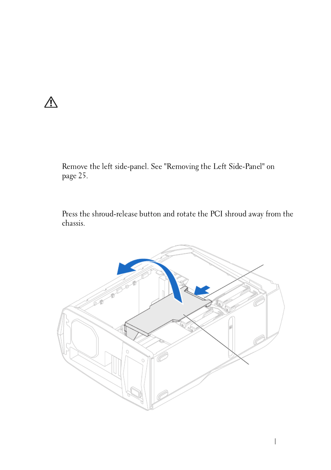
Opening the PCI Shroud
1
2
1

46 PCI Shroud
Closing the PCI Shroud
1
Postrequisites
1
2
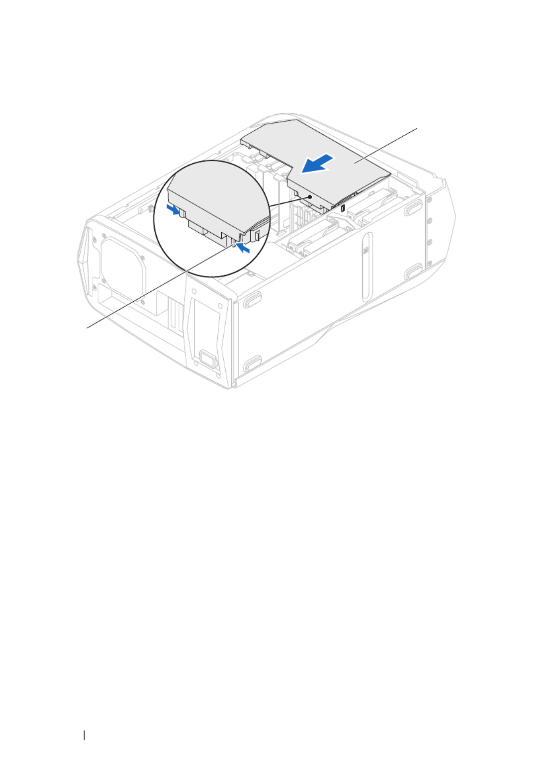
1 PCI shroud 2 shroud-release button

Drive-Bay Shroud 47
8
Drive-Bay Shroud
WARNING: Before working inside your computer, read the safety information
that shipped with your computer and follow the steps in "Before You Begin" on
page 13. For additional safety best practices information, see the Regulatory
Compliance Homepage at dell.com/regulatory_compliance.
Prerequisites
1
2
Removing the Drive-Bay Shroud
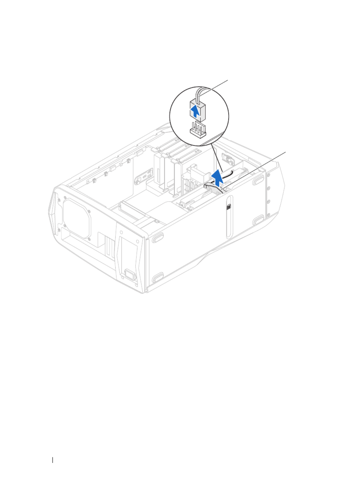
NOTE: Be careful not to damage the cable connected to the drive-bay shroud
while sliding the drive-bay shroud.
1
2
48 Drive-Bay Shroud
Replacing the Drive-Bay Shroud
1
Align the drive-bay shroud with the slots on the chassis.
2
Slide the drive-bay shroud toward the front of the chassis until it clicks
into place.
Postrequisites
1
Replace the left side-panel. See "Replacing the Left Side-Panel" on
page 27.
2
Follow the steps in "After Working Inside Your Computer" on page 15.
3
Close the PCI shroud. See "Closing the PCI Shroud" on page 46.
1 tabs (2) 2 drive-bay shroud
1
2

PCI-Express p49-x1 Card 49
9
PCI-Express p49-x1 Card
WARNING: Before working inside your computer, read the safety information
that shipped with your computer and follow the steps in "Before You Begin" on
page 13. For additional safety best practices information, see the Regulatory
Compliance Homepage at dell.com/regulatory_compliance.
Prerequisites
1
2
Removing the PCI-Express p49-x1 Card
1
9
2
3
4
NOTE: For removing a PCI-Express x16 card, see "Removing the Graphics Card" on
page 57.
NOTE: If you are not replacing a card, install a filler bracket in the empty card-slot
opening.

50 PCI-Express p50-x1 Card
Replacing the PCI-Express p50-x1 Card
1
1 screw 2 PCI-Express p50-x1 card
3 PCI-Express p50-x1 connector
1
3
2

PCI-Express p51-x1 Card 51
2
5 5
3
4
5
Postrequisites
1
1 screw 2 filler bracket
1
2
52 PCI-Express p52-x1 Card
2
3

PCI-Fan Assembly 53
10
PCI-Fan
WARNING: Before working inside your computer, read the safety information
that shipped with your computer and follow the steps in "Before You Begin" on
page 13. For additional safety best practices information, see the Regulatory
Compliance Homepage at dell.com/regulatory_compliance.
WARNING: The heat sink may be very hot during normal operation. Provide
sufficient time for the heat-sink to cool before you touch it.
Prerequisites
1
Removing the PCI-Fan
1
2
3
4

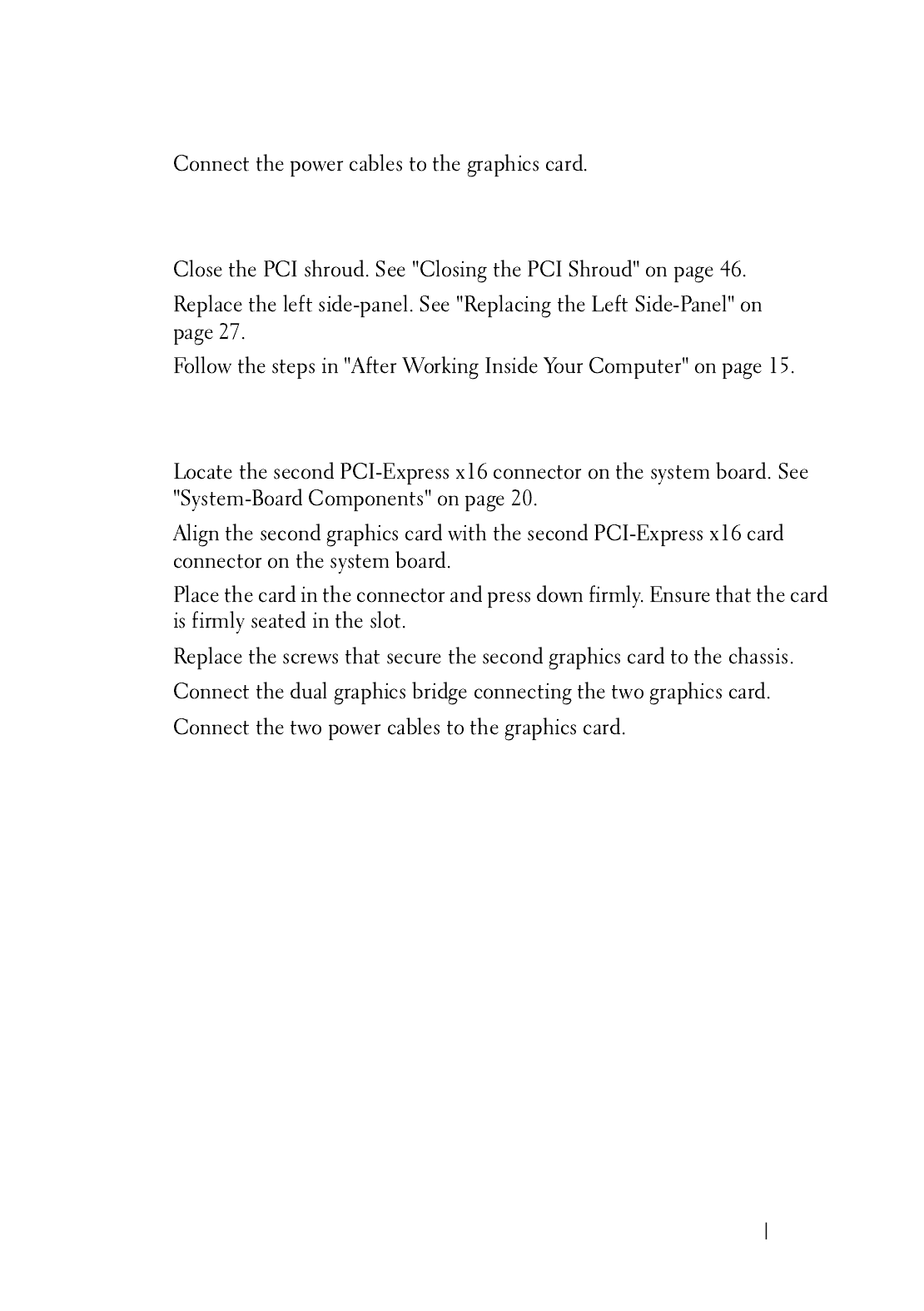
58 Graphics Card
Replacing the Graphics Card
1
2
3
1 screws (2) 2 graphics card
3 PCI-Express x16 connector 4 securing tab
5 power cables (2)
1
3
2
5
4
Graphics Card 59
4
Postrequisites
1
2
3
Installing Dual Graphic Cards
1
2
3
4
5
6
60 Graphics Card
7
Close the PCI shroud. See "Closing the PCI Shroud" on page 46.
8
Replace the left side-panel. See "Replacing the Left Side-Panel" on
page 27.
9
Follow the steps in "After Working Inside Your Computer" on page 15.
1 power cables (2) 2 Dual graphics bridge
3 screws (2) 4 PCI-Express x16 card
5 PCI-Express x16 connector
3
5
4
1
2

62 Graphics Card

Memory Module(s) 63
12
Memory Module(s)
WARNING: Before working inside your computer, read the safety information
that shipped with your computer and follow the steps in "Before You Begin" on
page 13. For additional safety best practices information, see the Regulatory
Compliance Homepage at dell.com/regulatory_compliance.
Prerequisites
1
2
Removing Memory Module(s)
WARNING: The memory module(s) may become very hot during normal operation.
Allow the memory module(s) to cool before touching them.
1
2
1 securing clip 2 memory-module connector
1
2
64 Memory Module(s)
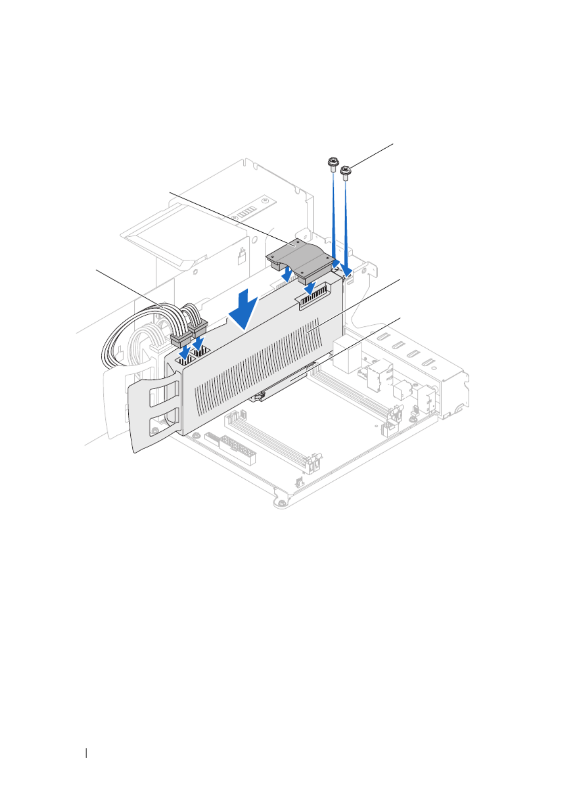
Replacing Memory Module(s)
CAUTION: If the memory module is not installed correctly, your computer may not
boot.
CAUTION: If you remove the original memory module(s) from your computer
during a memory upgrade, keep them separate from any new module(s) that you
may have, even if you purchased the new module(s) from Dell. If possible, do not
pair an original memory module with a new memory module. Otherwise, your
computer may not start properly. The recommended memory configurations are:
matched memory modules installed in DIMM connectors 1 and 2 and another
matched memory modules installed in DIMM connectors 3 and 4.
1
Type Slots
1333 MHz,1600 MHz, and 1866 MHz DDR3 Slots 1 and 2 or slots 1 through 4
76 Processor
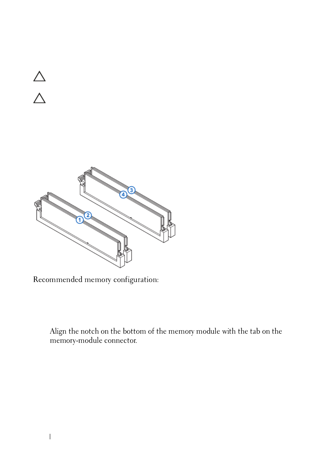
2
Press down and push the release lever away from the processor to release it
from the securing tab.
3
Extend this release lever completely to open the processor cover.
1 securing tab 2 release lever
3 processor cover 4 processor
1
2
3
4

Processor 77
CAUTION: When removing the processor, do not touch any of the pins inside the
socket or allow any objects to fall on the pins in the socket.
4
Open the processor cover and gently lift the processor from the processor
socket.
1 processor cover 2 processor
3 securing tab 4 release lever
1 processor 2 processor socket
13
4
2
2
1

78 Processor
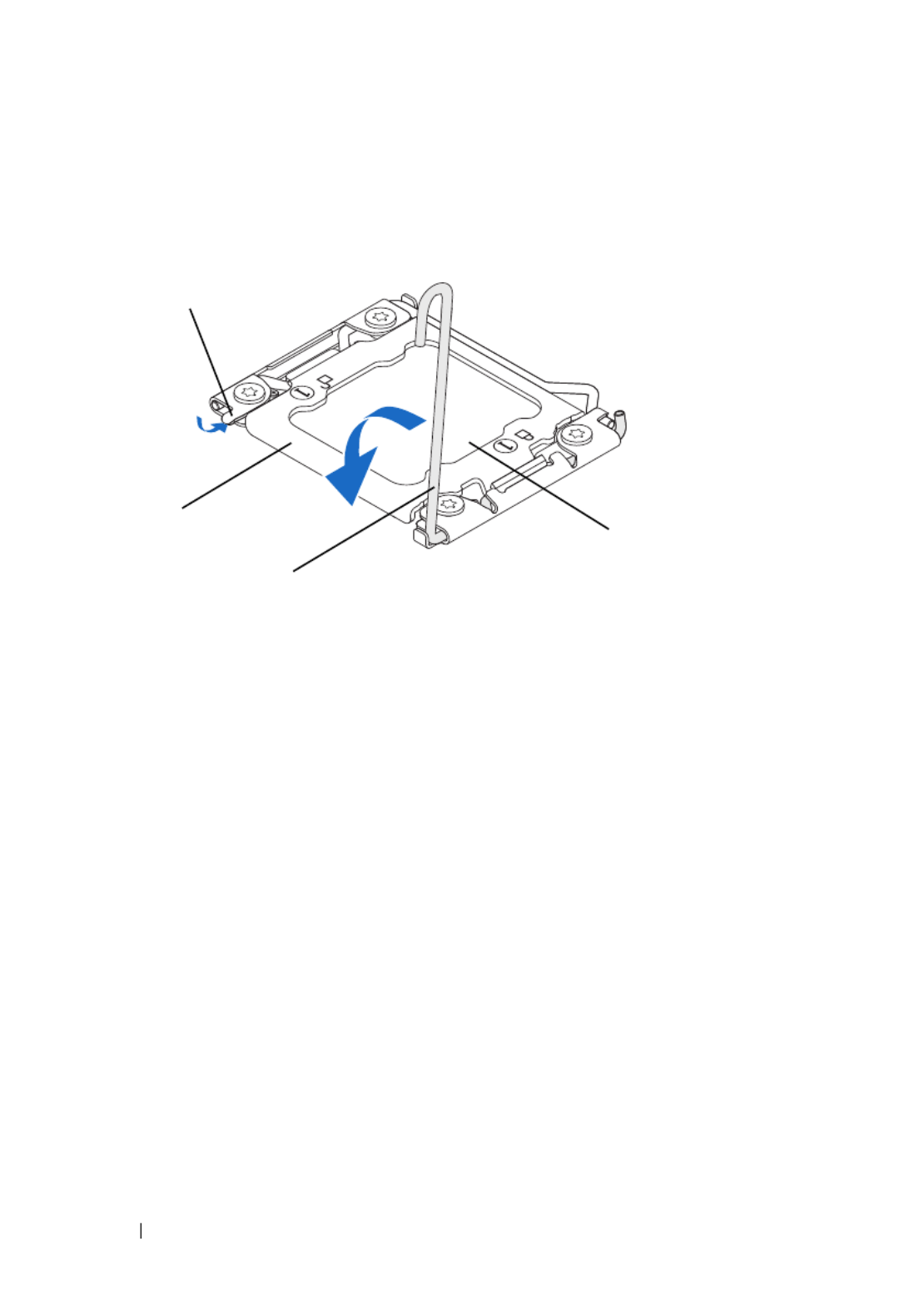
Replacing the Processor
1
Ensure that the second release lever is fully extended in the open position.
CAUTION: You must position the processor correctly in the processor socket to
avoid damage to the processor.
2
Align the pin-1 corner of the processor with the pin-1 corner of the
processor socket, and then place the processor in the processor socket.
3
When the processor is fully seated in the socket, close the processor cover.
4
Pivot the release lever down and place it under the tab on the processor
cover.
1 processor pin-1 indicator 2 processor
3 alignment notches (4) 4 alignment tabs (4)
5 processor socket
5
4
3
12
80 Processor
Postrequisites
1
Replace the processor liquid-cooling assembly. See "Replacing the
Processor Liquid-Cooling Assembly" on page 72.
2
Replace the left side-panel. See "Replacing the Left Side-Panel" on
page 27.
3
Follow the steps in "After Working Inside Your Computer" on page 15.
1 securing tabs 2 processor cover
3 release levers 4 processor
1
2
3
4

Power Supply 83
16
Power-Supply Unit
WARNING: Before working inside your computer, read the safety information
that shipped with your computer and follow the steps in "Before You Begin" on
page 13. For additional safety best practices information, see the Regulatory
Compliance Homepage at dell.com/regulatory_compliance.
Prerequisites
1
Remove the left side-panel. See "Removing the Left Side-Panel" on
page 25.
Removing the Power-Supply Unit
1
Lift and hold the tab on the power-supply cover, slide the power-supply
cover towards the back of the chassis, and remove the power-supply cover.
2
Lift the power-supply cover away from the chassis.

84 Power Supply
3
Press the securing clips on the DC-wire harness and disconnect the DC-
wire harness from the power-supply unit.
4
Loosen the captive screws that secure the power-supply unit to the back of
the chassis.
5
Slide the power-supply unit out through the back of the chassis.
1 power-supply cover 2 tab
2
1
Termékspecifikációk
| Márka: | Alienware |
| Kategória: | Asztali |
| Modell: | Aurora R4 |
Szüksége van segítségre?
Ha segítségre van szüksége Alienware Aurora R4, tegyen fel kérdést alább, és más felhasználók válaszolnak Önnek
Útmutatók Asztali Alienware

12 Január 2025
25 Augusztus 2024
17 Augusztus 2024
15 Augusztus 2024
14 Augusztus 2024
14 Augusztus 2024
14 Augusztus 2024
14 Augusztus 2024
11 Augusztus 2024
11 Augusztus 2024
Útmutatók Asztali
- Asztali Samsung
- Asztali Sony
- Asztali Fujitsu
- Asztali Acer
- Asztali Sharkoon
- Asztali Sharp
- Asztali Lenovo
- Asztali Toshiba
- Asztali HP
- Asztali BenQ
- Asztali Apple
- Asztali Medion
- Asztali LC-Power
- Asztali Dell
- Asztali Gigabyte
- Asztali Tripp Lite
- Asztali BDI
- Asztali Microsoft
- Asztali Asus
- Asztali Vtech
- Asztali PEAQ
- Asztali Haier
- Asztali Supermicro
- Asztali AOC
- Asztali Asrock
- Asztali Kobo
- Asztali Viewsonic
- Asztali MSI
- Asztali ZTE
- Asztali Kogan
- Asztali Mio
- Asztali Moxa
- Asztali Razer
- Asztali JYSK
- Asztali Vorago
- Asztali NEC
- Asztali Elo
- Asztali Axis
- Asztali ECS
- Asztali Planar
- Asztali Zotac
- Asztali Kramer
- Asztali Emachines
- Asztali Parisot
- Asztali Trekstor
- Asztali Maxdata
- Asztali Woood
- Asztali Wehkamp
- Asztali InFocus
- Asztali Intel
- Asztali Targa
- Asztali Seagate
- Asztali Shuttle
- Asztali VXL
- Asztali Promethean
- Asztali Foxconn
- Asztali Ibm
- Asztali Advantech
- Asztali MP
- Asztali Elitegroup
- Asztali Smart Things
- Asztali ONYX
- Asztali System76
- Asztali Zoostorm
- Asztali Bestar
- Asztali Pelco
- Asztali Cybernet
- Asztali Altra
- Asztali Dell Wyse
- Asztali AOpen
- Asztali NComputing
- Asztali MvixUSA
- Asztali Faytech
- Asztali AIS
- Asztali Wyse
- Asztali Kendall Howard
Legújabb útmutatók Asztali

9 Április 2025
2 Április 2025
1 Április 2025

30 Március 2025
28 Március 2025
18 Március 2025
13 Január 2025

12 Január 2025
12 Január 2025

12 Január 2025