Használati útmutató 3Com Router 3016
Olvassa el alább 📖 a magyar nyelvű használati útmutatót 3Com Router 3016 (72 oldal) a router kategóriában. Ezt az útmutatót 11 ember találta hasznosnak és 2 felhasználó értékelte átlagosan 4.5 csillagra
Oldal 1/72

http://www.3com.com/
Router 3000
Installation Guide
Router 3012
Router 3013
Router 3015
Router 3016
Part No. 10014206
Published September 2003

3Com Corporation
350 Campus Drive
Marlborough, MA
01752-3064
Copyright © 2003, 3Com Corporation. All rights reserved. No part of this documentation may be reproduced
in any form or by any means or used to make any derivative work (such as translation, transformation, or
adaptation) without written permission from 3Com Corporation.
3Com Corporation reserves the right to revise this documentation and to make changes in content from time
to time without obligation on the part of 3Com Corporation to provide notification of such revision or change.
3Com Corporation provides this documentation without warranty, term, or condition of any kind, either
implied or expressed, including, but not limited to, the implied warranties, terms or conditions of
merchantability, satisfactory quality, and fitness for a particular purpose. 3Com may make improvements or
changes in the product(s) and/or the program(s) described in this documentation at any time.
If there is any software on removable media described in this documentation, it is furnished under a license
agreement included with the product as rd copy documentation, or on the a separate document, in the ha
removable media in a directory file named LICENSE.TXT or !LICENSE.TXT. If you are unable to locate a copy,
please contact 3Com and a copy will be provided to you.
UNITED STATES GOVERNMENT LEGEND
If you are a United States government agency, then this documentation and the software described herein
are provided to you subject to the following:
All technical data and computer software are commercial in nature and developed solely at private expense.
Software is delivered as “Commercial Computer Software” as defined in DFARS 252.227-7014 (June 1995)
or as a “commercial item” as defined in FAR 2.101(a) and as such is provided with only such rights as are
provided in 3Com’s standard commercial license for the Software. Technical data is provided with limited
rights only as provided in DFAR 252.227-7015 (Nov 1995) or FAR 52.227-14 (June 1987), whichever is
applicable. You agree not to remove or deface any portion of any legend provided on any licensed program
or documentation contained in, or delivered to you in conjunction with, this User Guide.
Unless otherwise indicated, 3Com registered trademarks are registered in the United States and may or may
not be registered in other countries.
3Com and the 3Com logo are registered trademarks of 3Com Corporation.
Intel and Pentium are registered trademarks of Intel Corporation. Microsoft, MS-DOS, Windows, and
Windows NT are registered trademarks of Microsoft Corporation.
All other company and product names may be trademarks of the respective companies with which they are
associated.

CONTENTS
ABOUT THIS GUIDE
Conventions 5
OVERVIEW
Router 3012 7
Router 3013 and Router 3015 11
Router 3016 14
P REPARING TO INSTALL THE ROUTER
Safety Warnings 19
General Site Requirements 19
Preventing Lightning Damage 21
Workbench Requirements 22
I NSTALLING THE ROUTER
Mounting the Router on a Vertical Surface 23
Installing the Router on a Workbench 24
Connecting the Protection Ground Wire 24
Connecting the Power Cable 24
Connecting the Router to the Console Terminal 25
Connecting the Router to the Ethernet 26
Connecting the Router to the WAN 27
Verifying the Installation 33
B OOTING AND CONFIGURING THE ROUTER
Connecting the Router to a Local Console Terminal 35
Setting the Parameters of the Console Terminal 35
Powering on the Router 39
Startup Process 39
Configuration Fundamentals of the Router 40
M AINTAINING THE ROUTER
Software Maintenance 43
Maintaining Router Hardware 52

TROUBLESHOOTING
The Power LED is Off. 55
Nothing is Displayed on the Terminal after Power-On 55
Illegible Characters Display on the Terminal after Power-On 56
OPTIONAL C SABLE PECIFICATIONS
Console Cable 57
AUX Cable 57
Ethernet Cable 58
Serial Interface Cable 59
T1 Cable 64
ISDN Cable 64
TECHNICAL SUPPORT
Online Technical Services 67
Support from Your Network Supplier 68
Support from 3Com 68
Returning Products for Repair 70

6CHAPTER : ABOUT T GHIS UIDE
1
OVERVIEW
The 3Com® Router 3000 series routers provide the following types of interfaces:
■Ethernet interface
■Synchronous/asynchronous serial interface
■Auxiliary (AUX) port
■ISDN BRI S/T and U port
■CT1/PRI port
These features allow you to combine the various technologies, such as PSTN/ISDN,
FR (Frame Relay), X.25, leased line, and T1 line, for networking. These multiple
interfaces also allow Router 3000 series routers to interoperate with the products
of other manufacturers on all levels.
Router 3000 routers use three types of memory:
■Synchronous Dynamic Random Access Memory (SDRAM) — Saves router
operation system software
■Flash memory — Saves router program files, configuration files and so on
■Boot ROM — Saves boot and initialization programs of the router
Router 3012 Figure 1 illustrates the Router 3012.
Figure 1 Router 3012
Power LED
100M Ethernet LED
SERIAL0 LED
SERIAL1 LED
AUX LED
System LED

8CHAPTER 1: OVERVIEW
Figure 2 illustrates the back panel of the Router 3012.
Figure 2 Back Panel of the Router 3012
System Specifications Table 1 lists system specifications for the Router 3012.
LEDs Table 2 lists and describes the LEDs on the front panel of the Router 3012.
Power
switch
Power
input
socket
Console
port
AUX
port
100M
Ethernet
port
Grounding
screw
SERIAL0 SERIAL1
Table 1 System Specifications for the Router 3012
Item Description
Port 1 10/100M Ethernet port
2 synchronous/asynchronous serial interfaces
1 AUX port
1 console port
Processor MPC860T 50MHz
SDRAM 64MB
Flash memory 8MB
Maximum power 20 W
Power supply (external) Input voltage and frequency: 100 to 240V AC (the actual range can
be 80 to 264 V) 50/60Hz
Input current: 0.5A to 1A
Output voltage: 12V
Output current: 4A
Dimensions (W X H X
D, highest arc points of
the plastic panel)
251mm X 42.5 mm X 187mm (9.9in X 1.7in X 7.4in)
Weight 0.75kg (1.65lb)
Operating temperature 0 to 40
0C (32 to 1040F)
Relative humidity 5 to 85% (noncondensing)
Table 2 Router 3012 LEDs
LED Description
POWER Off means that power is not being supplied.
Green means that power is being supplied.
100M ETH Off means that the link is not connected.
Flashing green means that data is being sent or received over the
Ethernet interface.

Router 3012 9
Interface Attributes The Router 3012 provides a console port, an AUX port, a 10/100M Ethernet
interface and a synchronous/asynchronous serial interface. The attributes of these
interfaces are described in the following sections.
Console Port
Table 3 lists attributes of the console port.
AUX Port
Table 4 . lists attributes of the AUX port
SERIAL0 Off means that the link is not connected.
Green means that the link is connected.
Flashing green means that data is being sent or received over the
synchronous/asynchronous port 0.
SERIAL1 Off means that the link is not connected.
Green means that the link is connected.
Flashing green means that data is being sent or received over the
synchronous/asynchronous port 1.
AUX Off means that the link is not connected.
Green means that the link is connected.
Flashing green means that data is being sent or received over the
AUX port.
SYSTEM Flashing green means that the system is properly working.
Always green or off means that the system is not working properly.
Table 2 Router 3012 LEDs (continued)
LED Description
Table 3 Attributes of the Console Port
Attribute Description
Connector RJ45
Interface standard Asynchronous EIA/TIA-232
Baud rate 9600 to 115200bps
Defaults to 9600bps
Services Connects with ASCII terminal
Connects with serial interfaces of the local PCs and runs the terminal
emulation program on the PCs
Command line interface
Table 4 Attributes of the AUX Port
Attribute Description
Connector RJ45
Interface standard Asynchronous EIA/TIA-232
Baud rate 300 to 115200bps
Services Modem dial-up
Backup

10 CHAPTER 1: OVERVIEW
Ethernet Interface
Table 5 lists attributes of the Ethernet interface.
Synchronous/Asynchronous Serial Interface
Table 6 lists attributes of the synchronous/asynchronous serial interface.
Protocols PPP (Point to Point Protocol)
SLIP (Serial Line Internet Protocol)
MP (Multilink PPP)
Table 5 Attributes of the Fast Ethernet Interface
Attribute Description
Connector RJ45
Frame format Ethernet_II
Ethernet_SNAP
IEEE 802.2
IEEE 802.3
Operating mode 10/100Mbps autosensing
Full duplex/half duplex
Network protocol IP (Internet Protocol)
Novell IPX (Internet Packet Exchange)
Table 6 Attributes of the Synchronous/Asynchronous Serial Interface
Attribute
Description
Synchronous Asynchronous
Connector DB50
Interface standard
and operating
mode
V.24
(EIA/TIA-23
2)
V.35 EIA/TIA-449, X.21 and
EIA-530
V.24 (EIA/TIA-232)
DTE, DCE DTE, DCE DTE DCE
Minimum baud
rate (bps)
1200 1200 1200 1200 300
Maximum baud
rate (bps)
64 k 2.048 M 2.048 M 2.048 M 115.2 k
Services DDN leased line
Terminal access
Backup
Modem dial-up
Backup
Protocols PPP
MP
LAPB (Link Access Protocol-Balanced)
HDLC (High-level Data Link Control)
SDLC (Synchronous Data Link Control)
X.25
Frame Relay
PPP
SLIP
MP
Table 4 Attributes of the AUX Port
Attribute Description

Router 3013 and Router 3015 11
Router 3013 and
Router 3015
Figure 3 illustrates the Router 3013 and Router 3015 routers.
Figure 3 Router 3013 and Router 3015
Figure 4 illustrates the back panel of the Router 3013 and 3015.
Figure 4 Back Panel of the Router 3013 and Router 3015
System Specifications Table 7 lists system specifications for the Router 3013 and Router 3015.
Power LED
100M Ethernet LED
Serial LED
BRI LED
AUX LED
System LED
OFF ON DC12V
CON AUX 100M ETH SERIAL BRI
Power
switch
Power
input
socket
CON
port
AUX
port
100M
Ethernet
port SERIAL0
Grounding
screw
BRI port
Table 7 System Specifications for the Router 3013 and Router 3015
Item Router 3013 Description Router 3015 Description
Port 1 console port
1 10/100M Ethernet interface
1 AUX port
1 synchronous/asynchronous
serial interface
1 ISDN BRI S/T port
1 console port
1 10/100M Ethernet interface
1 AUX port
1 synchronous/asynchronous serial
interface
1 ISDN BRI U port
Processor MPC860T 50MHz
SDRAM 64 MB
Flash memory 8 MB
Maximum
power
20 W
Power supply
(external)
Input voltage and frequency: 100 to 240V AC (the actual range can be 80 to
264 V) 50/60 Hz
Input current: 0.5 A to 1A
Output voltage: 12V
Output current: 4A
Dimensions (W
X H X D, the
highest arc
points of the
plastic panel)
251mm X 42.5 mm X 187mm (9.9in X 1.7in X 7.4in)

12 CHAPTER 1: OVERVIEW
LEDs Table 8 lists and describes the LEDs on the front panel of the Router 3013 and
Router 3015.
Interface Attributes The Router 3013 and Router 3015 provide a console port, an AUX port, a
10/100M Ethernet interface, a synchronous/asynchronous serial interface, and an
ISDN S/T or U port.
Console Port
Table 9 lists attributes of the console port.
Weight 0.75kg (1.65lb)
Operating
temperature
0 to 40C (32 to 1040F)
Operating
humidity
5 to 85% (noncondensing)
Table 7 System Specifications for the Router 3013 and Router 3015 (continued)
Item Router 3013 Description Router 3015 Description
Table 8 Router 3013 and Router 3015 LEDs
LED Description
POWER Off means that power is not being supplied.
Green means that power is being supplied.
100M ETH Off means that the link is not connected.
Flashing green means that data is being sent or received over the
Ethernet interface.
SERIAL Off means that the link is not connected.
Green means that the link is connected.
Flashing green means that data is being sent or received over the
synchronous/asynchronous port.
BRI Off means that no data is being sent or received over the ISDN BRI
port and two B channels are free.
Flashing green means that data is being sent and received over the
ISDN BRI port.
AUX Off means that the link is not connected.
Green means that the link is connected.
Flashing green means that data is being sent or received over the
AUX port.
SYSTEM Flashing green means that the system is properly working.
Always green or off means that the system is incorrectly working.
Table 9 Attributes of the Console Port
Attribute Description
Connector RJ45
Interface standard Asynchronous EIA/TIA-232
Baud rate 9600 to 115200bps (9600bps is the default)

Router 3013 and Router 3015 13
AUX Port
Table .10 lists attributes of the AUX port
Ethernet Interface
Table 11 lists attributes of the Ethernet interface.
Synchronous/Asynchronous Serial Interface
Table 12 lists attributes of the synchronous/asynchronous serial interface.
Services Connects with ASCII terminal
Connects with serial interfaces of the local PCs and runs the terminal
emulation program on the PCs
Command line interface
Table 10 Attributes of the AUX Port
Attribute Description
Connector RJ45
Interface standard Asynchronous EIA/TIA-232
Baud rate 300 to 115200bps
Services Modem dial-up
Backup
Protocols PPP (Point to Point Protocol)
SLIP (Serial Line Internet Protocol)
MP (Multilink PPP)
Table 11 Attributes of the Fast Ethernet Interface
Attribute Description
Connector RJ45
Frame format Ethernet_II
Ethernet_SNAP
IEEE 802.2
IEEE 802.3
Operating mode 10/100Mbps autosensing
Full duplex/half duplex
Network protocol IP (Internet Protocol)
Novell IPX (Internet Packet Exchange)
Table 12 Attributes of the Synchronous/Asynchronous Serial Interface
Attribute
Description
Synchronous Asynchronous
Connector DB50
Interface standard
and operating
mode
V.24
(EIA/TIA-23
2)
V.35 EIA/TIA-449, X.21 and
EIA-530
V.24 (EIA/TIA-232)
DTE, DCE DTE, DCE DTE DCE
Table 9 Attributes of the Console Port (continued)
Attribute Description

14 CHAPTER 1: OVERVIEW
ISDN S/T and U ports
Table 13 lists attributes of the ISDN S/T and U ports.
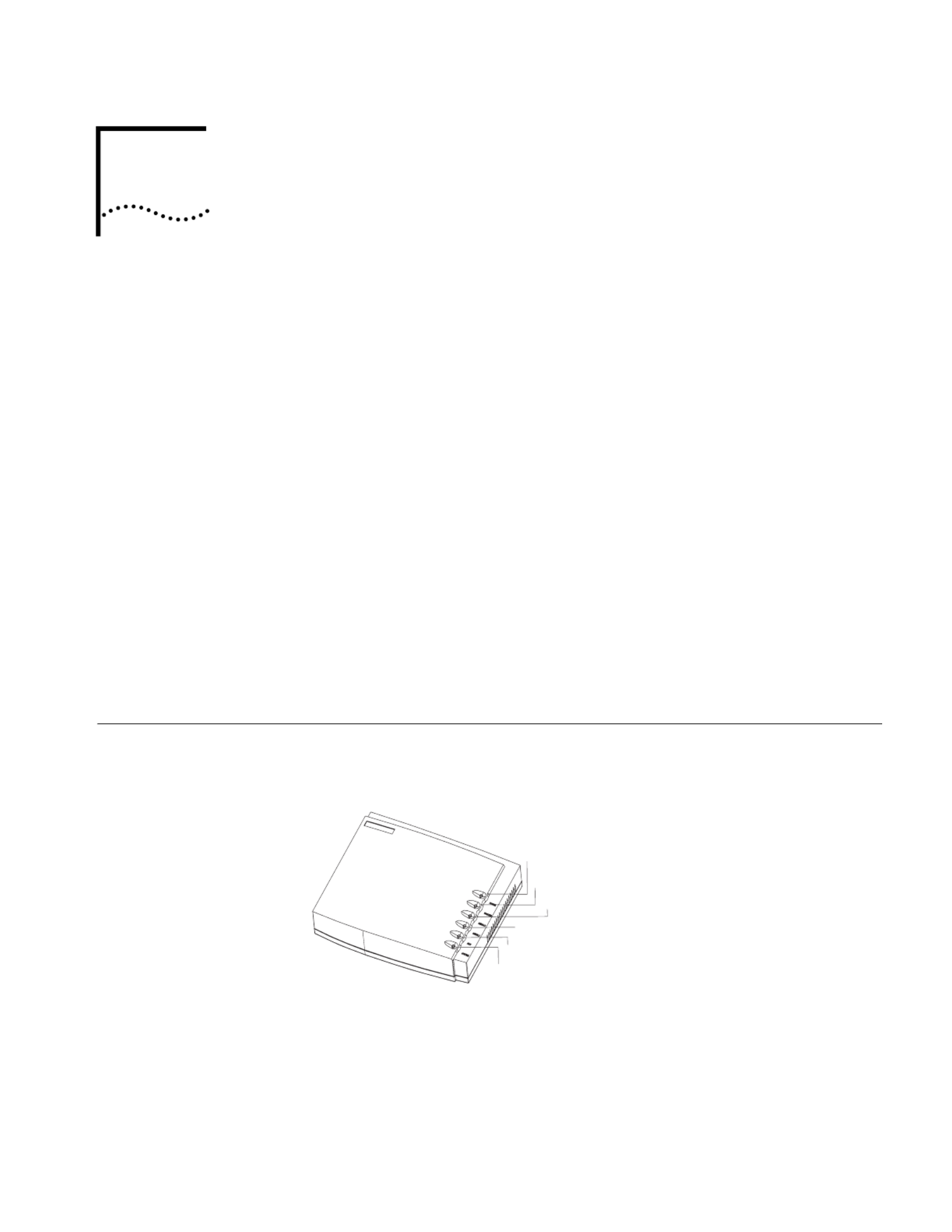
Router 3016 Figure 5 illustrates the Router 3016.
Figure 5 Router 3016
Minimum baud
rate (bps)
1200 1200 1200 1200 300
Maximum baud
rate (bps)
64 k 2.048 M 2.048 M 2.048 M 115.2 k
Services DDN leased line
Terminal access
Backup
Modem dial-up
Backup
Protocols PPP
MP
LAPB (Link Access Protocol-Balanced)
HDLC (High-level Data Link Control)
SDLC (Synchronous Data Link Control)
X.25
Frame Relay
PPP
SLIP
MP
Table 13 Attributes of ISDN S/T and U Ports
Attribute Description
Connector RJ45
Protocol standards Complies with ITU-T I.430, Q.921 and Q.931 recommendations
Operating mode ISDN dial-up
ISDN leased line
Services ISDN
ISDN additional services
Multi-subscriber number
Subaddress
Backup
Table 12 Attributes of the Synchronous/Asynchronous Serial Interface (continued)
Attribute
Description
Synchronous Asynchronous
Power LED
Ethernet LED
T1-LNK LED
T1-ACT LED
AUX LED
System LED

Router 3016 15
Figure 6 illustrates the back panel of the Router 3016.
Figure 6 Back Panel of the Router 3016
System Specifications Table 14 lists system specifications for the Router 3016.
LEDs Table 15 lists and describes the LEDs on the Router 3016.
OFF ON DC12V
CON AUX 100METH CT1/PRI
Power
switch
Power
input
socket
CON
port
AUX
port
100M
Ethernet
port
Grounding
screw CT1/PRI
port
Table 14 System Specifications for the Router 3016
Item Description
Port 1 console port
1 10/100Mbps Ethernet interface
1 AUX port
1 CT1/PRI port
Processor MPC860T 50MHz
SDRAM 64 MB
Flash memory 8 MB
Maximum power 20 W
Power supply (external) Input voltage and frequency: 100 to 240V AC (the actual range can
be 80 to 264 V) 50/60 Hz
Input current: 0.5A to 1A
Output voltage: 12V
Output current: 4A
Dimensions (W X H X
D, the highest arc
points of the plastic
panel)
251mm X 42.5 mm X 187mm (9.9in X 1.7in X 7.4in)
Weight 0.75kg (1.65lb)
Operating temperature 0 to 40 0C (32 to 104 0F)
Operating humidity 5 to 85% (noncondensing)
Table 15 Router 3016 LEDs
LED Description
POWER Off means that power is not being supplied.
Green means that power is being supplied.
100M ETH Off means that the link is not connected.
Flashing green means that data is being sent from or to the Ethernet
interface.
T1-LNK Off means that the link is not set up.
Green means that the link has been set up.

Router 3016 17
Ethernet Interface
Table 18 lists attributes of the Ethernet interface.
CT1/PRI Port
Table 19 lists attributes of the CT1/PRI port.
Table 18 Attributes of the Fast Ethernet Interface
Attribute Description
Connector RJ45
Frame format Ethernet_II
Ethernet_SNAP
IEEE 802.2
IEEE 802.3
Operating mode 10/100Mbps autosensing
Full duplex/half duplex
Network protocol IP (Internet Protocol)
Novell IPX (Internet Packet Exchange)
Table 19 Attributes of the CT1/PRI Port
Attribute Description
Connector RJ45
Interface standard G.703/T1 102 and G.704
Interface rate 1.544Mbps
Operating mode Channelized T1
ISDN PRI
Services Backup
Terminal access
ISDN
Protocols PPP
MP
HDLC
LAPB
X.25 (ITU-T X series Recommendations)
Frame Relay
Q.921
Q.931
Q.SIG

18 CHAPTER 1: OVERVIEW

2
PREPARING TO INSTALL THE OUTER R
Safety Warnings As you prepare to install your router, consider the following safety guidelines:
■Switch off the power supply before connecting the cables.
■Keep the router far away from any heat source.
■To ensure normal heat dissipation, do not stack routers during the installation.
■Do not keep a router in a damp place, and prevent liquid from getting into the
router.
■Make sure that the neutral point of the power is grounded properly, to avoid
personal injury.
■Make sure that the power is off before plugging or unplugging the interface
cards, modules and cables of the router.
■Before removing the chassis, disconnect all the power cords and external
cables.
■To avoid damage to the router, connect all the cables correctly, and never
connect telephone cables (including the ISDN lines) to the console or AUX port.
■During the installation, wear the ESD (Electro-Static Discharge) preventive wrist
strap and ESD-preventive gloves. See the Static Electricity section in this chapter
for additional information on ESD prevention.
■3Com recommends that you use an uninterrupted power supply (UPS) with
your router.
■To enhance the anti-lightning-strike capability of the router, install a power
arrester at the front end of the power input, and a special arrester at the input
end of the outdoor cable, such as telephone cable, ISDN line or T1/E1 line.
General Site
Requirements
The environment of the installation site influences the performance and lifetime of
the router. In addition, if the router operates in inappropriate working
environment, its performance will become unreliable. The installation site for your
router should meet the following requirements for temperature and humidity,
dust, gases, static electricity, and electromagnetic discharge.
Temperature and
Humidity
To ensure normal operation and to prolong the operational lifetime of the router,
the equipment room must maintain adequate temperature and humidity. If the
equipment room is damp, it is likely to affect the performance of the insulating
material, which may result in electric leakage and lead to metal erosion.
If the equipment room is very dry, the insulating shim will contract, leading to
loosening of the fastening screws. In addition, static electricity will be produced,
which damages the complementary metal-oxide-semiconductor (CMOS) circuit on

20 C HAPTER 2: PREPARING TO INSTALL THE ROUTER
the router. If the equipment is always very hot, the aging process of insulating
materials accelerates, which affects the reliability of the router and even its
operational lifetime. The requirements for the temperature and humidity of the
router installation site are listed in Table 1.
Table 1 Temperature and Humidity Requirements
Dust Dust is harmful to the safe operation of the router. Dust on the chassis can result
in static absorption and cause faulty contact between metal connection
components or points. Especially when indoor humidity is low, dust is absorbed
more easily which not only shortens the operational lifetime of the equipment, but
also can result in communication failure. The specifications for the dust content
and diameter of the granule within the equipment room are listed in Table 2.
Table 2 Specification for Dust Content
Gases Besides the dust specification, the equipment room should also meet strict
requirements for the content of salt, acid and sulfide. These harmful gases can
accelerate the metal erosion and the aging process of some parts. The presence of
harmful gases, such as SO 2, H2S, NO2, NH3, and Cl 2, should be prevented. The
specific limitation values of these harmful gases are given in Table 3.
Table 3 Harmful Gas Limitation Values in Equipment Room
Static Electricity Although careful considerations in preventing electrostatic discharge (ESD) have
been taken in the design of the router, if the level of static electricity exceeds a
certain threshold, it will cause great damage to the circuit and even to the entire
router.
On the communication network connected to the router, the electrostatic
induction comes mainly from two aspects: one is from the outside electrical fields,
such as the outdoor high-voltage power cable and lightning, and the other is from
the inside system, such as indoor environment, floor material and the system
structure.
Temperature Relative humidity
00 to 40 0C (320 to 104 0F) 5% to 85%
Maximum diameter (µ m) 0.5 1 3 5
Maximum density (the number
of granules per cubic meter)
1.4 x 10 77 x 10 52.4 x 10 51.3 x 10 5
Gas Average (mg/m 3) Maximum (mg/m 3)
SO20.2 1.5
H
2S 0.0 0.03
NO20.04 0.15
NH
30.05 0.15
Cl20.01 0.3

22 C HAPTER 2: PREPARING TO INSTALL THE ROUTER
Workbench
Requirements
Whether you install the router in a cabinet or directly place it on the workbench, it
is necessary to ensure that:
■There is spacing reserved at the air inlet and outlet in the router so as to
facilitate the ventilation of the router cabinet.
■The cabinet and workbench are firm enough to support the weight of the
router and other installation accessories.
■The cabinet and workbench are well grounded.
Inspecting the Router
and Accessories
After you verify that the installation conditions comply with these requirements,
open the packing case of the router and check the contents against the your order
contract. Contact your Service representative if you find any discrepancies.
Installation Equipment To install your router, you will need:
■Tools
Phillips screwdriver
Flat-head screwdriver
ESD-preventive wrist strap and ESD-preventive gloves
Flat-blade screws (used in wall mounting)
■Cables
Ethernet cable
Console cable
AUX cable
Power supply, power cord, and chassis ground wire
Interface cables for the selected interface modules
■Equipment
A router
Ethernet 10/100Base-T Hub or LAN switch
Channel service unit/data service unit (CSU/DSU) or other data communications
equipment (DCE) equipment (such as a modem)
Configuration terminal, such as a PC
Additional equipment for the selected interface modules

24 C HAPTER 3: INSTALLING THE ROUTER
Figure 2 Hanging the Router on a Vertical Surface
Installing the Router
on a Workbench
To install the router on a workbench, take the following precautions:
■Make sure that the workbench is smooth and stable.
■Leave a heat-dissipation clearance of 10cm (4in) around the router.
■Do not put heavy things on the router.
Connecting the
Protection Ground
Wire
Properly connect the protection ground (PGND) wire before connecting other
cables. Shorten the ground wire as much as possible to avoid the router and the
peer device being damaged during lightning.
The AC input of the router is connected to an AC noise filter whose neutral point
is connected to the chassis directly, that is PGND (protection ground). The chassis
must be grounded properly, to improve the router’s ability to resist electromagnetic
interference. The PGND also provides protection for the external network, to
ensure that the PGND wire lets out the lightning current.
The grounding point of the chassis is located on the rear panel and is labeled with
a grounding label. The grounding resistance should not be greater than 5 ohm.
Connect this point to the ground using a grounding wire.
Connecting the Power
Cable
External AC power supplies are provided for Router 3000 series routers. The
power supplies have the following specifications:
■Input: 100 to 240VAC, 50/60Hz, 0.5 to 1 A
■Output: 12VDC, 4A
Connect the power supply to a 3-core outlet with a neutral point. The neutral
point of the outlet should be grounded reliably.
To connect the power supply:
1Turn off the power to the router.
2Connect the output end of the power supply to the power socket on the rear
panel of the router.
3Connect the input end of the power supply to the AC power outlet.
4Turn on the power switch on the router.
5Confirm that the router has power by checking whether the POWER LED is on.
Pan-head screw

Connecting the Router to the Console Terminal 25
Figure 3 illustrates the power supply.
Figure 3 Router 3000 Power Supply
To connect the AC power cord:
1Turn off the power to the router.
2Connect the output of the power supply to the power input on the rear panel of
the router.
3Insert the input connector of the power supply into an AC power outlet.
4Turn on the power the power to the router.
5Confirm that the router has power by checking whether the POWER LED is on.
6If you repeat this procedure several times and the POWER LED remains off, see
Chapter 6, Troubleshooting.
Connecting the Router
to the Console
Terminal
The Router 3000 series routers provide an EIA/TIA-232 asynchronous serial console
port, through which you can configure the router.
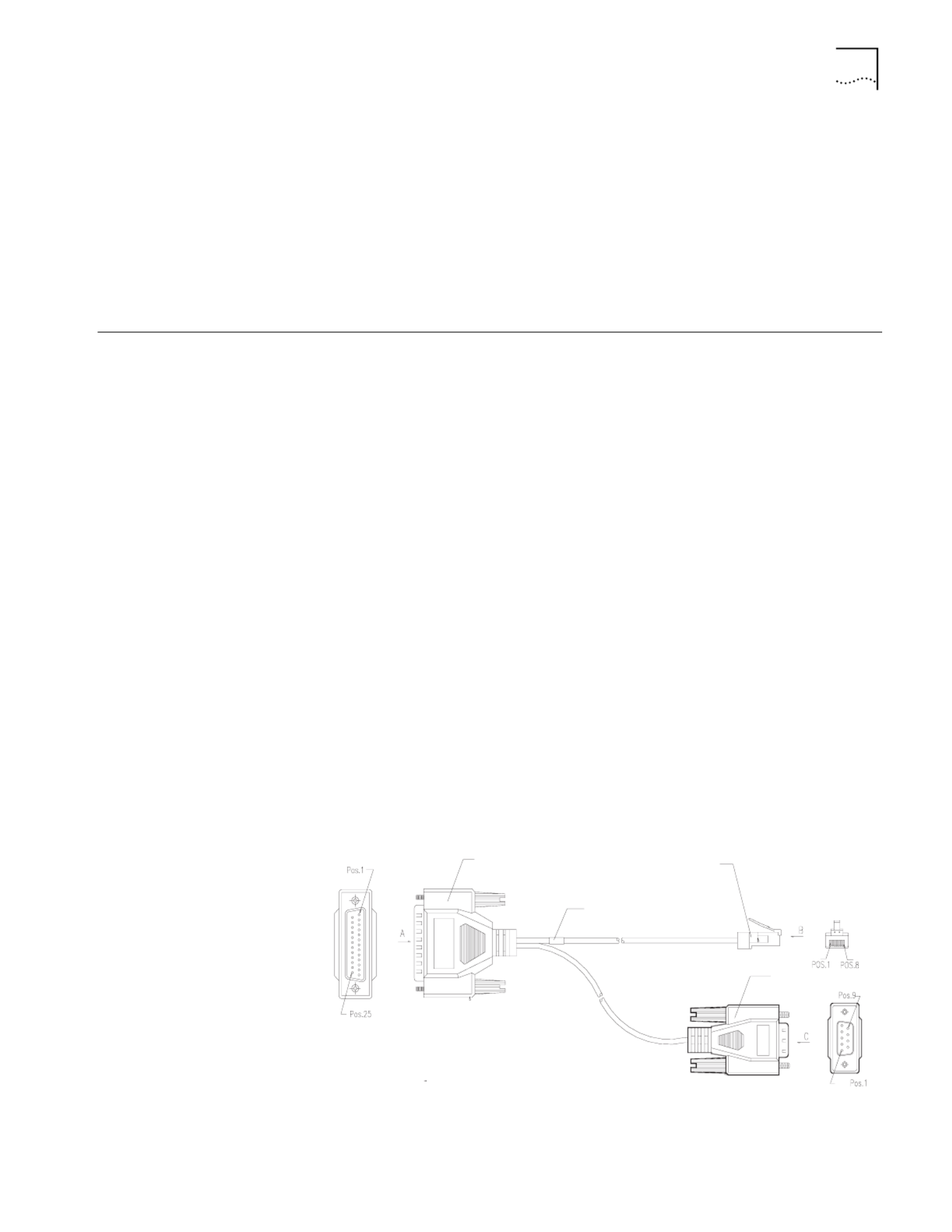
The console cable is an 8-core shielded cable. The end that is used to connect to
the console port of the router has an RJ-45 connector. The other end of the
console cable has both a DB-9 (female) adapter and a DB-25 (female) adapter. Use
the appropriate connector for the port on the console terminal.
Figure 4 illustrates the console cable.
Figure 4 Console Cable Assembly
See Appendix A for the pinout details of the console cable.
Enlarged A side DB25 Female
8P8C Plug
Enlarged B side
DB9 Female
Enlarged C side

26 C HAPTER 3: INSTALLING THE ROUTER
To configure the router through the console terminal:
1Turn off power to the router.
2Select a console terminal — The console port can be either a standard ASCII
terminal with an RS-232 serial interface, or a PC.
3Connect the cable — Turn the power switch off, and then connect the RS-232
serial interface of the console cable to the console port of the router.
After the connection and verification, power on the router. The startup
information of the router is displayed on the console terminal.
Connecting the Router
to the Ethernet
The Router 3000 series routers provide a fixed 10/100BASE-TX fast Ethernet
interface that uses category-5 twisted pair cable, as shown in Figure 5
Figure 5 Ethernet Cable Assembly
The Ethernet cables are classified as straight-through network cable and crossover
network cable. They have the following features:
■Straight-through network cable — The sequences of the wires crimped at the
RJ-45 connectors of the two ends are the same. The cable is used in the
connection between a terminal device, such as a PC or a router, and the Hub or
LAN Switch. Straight-through network cables are delivered along with the
router.
■Crossover network cable — The sequences of the wires crimped at the RJ-45
connectors of the two ends are different. The cable is used in the connection
between the terminal device, such as a PC or a router, and another terminal
device. You can create this cable yourself, if necessary.
For the pinouts, identification and making of the two network cables, see
Appendix A. Take the following considerations into account before you connect:
■The fixed Ethernet cables are included in the standard configuration of the
router.
■Use shielded cables to ensure electromagnetic compatibility.
■Identify the mark on the module port so you can plug the cable in correctly.
■When connecting the Ethernet cable to a LAN Switch, plug the cable into the
10/100BASE-T interface marked with MDIX.
To connect the Ethernet cable:
1Turn off power to the router.
2Select the Ethernet cable.
When connecting the router with a PC or a router, use the crossover network
cable.
Connecting the Router to the WAN 27
When connecting the router to a hub or a LAN switch, use the straight-through
network cable.
3Connect one end of the Ethernet cable to the appropriate Ethernet module on the
router.
4Connect the other end of the Ethernet cable to the Ethernet interface of the Hub
or the LAN switch.
5Verify the connection by checking that the 100M ETH LED on the top of the router
is on.
Connecting the Router
to the WAN
The Router 3000 series routers provide the following WAN interfaces:
■AUX port (all models)
■Mutiprotocol synchronous/asynchronous serial port (Router 3012, Router
3013, Router 3015)
■ISDN S/T (Router 3013)
■ISDN U (Router 3015)
■CT1/PRI ( Router 3016)
Connecting the AUX
Port to the Modem
The auxiliary (AUX) port is an EIA/TIA-232-compliant sync/async serial interface
that is used for remote configuration or dial-up backup. To be connected to a
remote device, a local modem must be connected to a remote modem through
PSTN. For the connection method, see Chapter 4, Booting and Configuring the
Router. If the console port fails, the AUX port can also serve as a console port. For
AUX port specifications, see Chapter 1, Overview.
The AUX cable is an 8-core shielded cable. One end of the cable has an RJ-45
connector and connects to the AUX port of the router. The other end has both a
DB-25 (male) adapter and a DB-9 (male) adapter. Use the appropriate connector
for the port on the modem.
Figure 6 illustrates the AUX cable.
Figure 6 AUX Cable Assembly
Enlarged B side
Enlarged A side
Enlarged C sid
e
DB25 Male
Label
DB9Male
8P8C Plug

28 C HAPTER 3: INSTALLING THE ROUTER
To connect the AUX cable:
1Turn off power to the router.
2Plug the RJ-45 connector of the AUX cable into the AUX port of the router.
3Connect the DB-25 or DB-9 adapter of the AUX cable to the serial interface of the
analog modem.
For pinout details of the AUX cable, see Appendix A.
Connecting the
Synchronous/
Asynchronous Serial
Interface to a CSU/DSU
The synchronous/asynchronous serial interface is usually used to connect a WAN
device, such as a modem, and a CSU/DSU. It can operate in
synchronous/asynchronous mode and DTE/DCE mode. For the attributes of the
interface, see Chapter 1 ., Overview
Synchronous and Asynchronous mode
V.35 and V.24 (EIA/TIA-232) standards support synchronous operating mode,
while only V.24 (EIA/TIA-232) standard supports the asynchronous operating
mode. The maximum transmission distance and baud rate of the signal vary with
the operating mode. See Table 1 for the details.
Table 1 Transmission Rate and Transmission Distance of V.24 (EIA/TIA-232)/V.35 Cable
Caution: The baud rate should not exceed 64 Kbps when the V.24 cable operates
in synchronous mode.
DTE and DCE mode
The synchronous serial interface can operate in both DTE mode and DCE mode.
For two devices connected directly, one device should operate in DTE mode, and
the other device should operate in DCE mode. The DCE mode device provides a
synchronous clock and specifies the transmission rate, the DTE mode device
accepts the synchronous clock and communicates at the specified transmission
rate. Usually, the router serves as the DTE device. To determine whether the device
is a DTE or a DCE, refer to the user manual for the device. Table 2 helps identify
DTE and DCE devices.
Table 2 Typical DTE and DCE
V.24 (EIA/TIA-232) V.35
Baud Rate (bps)
Maximum
Transmission
Distance (m) Baud Rate (bps)
Maximum
Transmission
Distance (m)
2400 60 2400 1250
4800 60 4800 625
9600 30 9600 312
19200 30 19200 156
38400 20 38400 78
64000 20 56000 60
115200 10 64000 50
- - 2048000 30
Type of
Equipment Type of Interface Typical Equipment

Connecting the Router to the WAN 29
In general, the asynchronous serial interface is connected to a modem or a
terminal adapter (TA) to act as the dial-up interface. In this case, it is unnecessary
to determine whether the device is DTE or DCE, you must only select the
appropriate baud rate.
The synchronous/asynchronous serial interface cable is connected to a DB-50
receptacle. Proper connection cable needs to be selected for the protocol applied.
Nine types of synchronous/asynchronous serial interface cables are available.
However, these cables are optional and you must select the proper one based on
your requirements when you purchase the router All these types of cables have a
DB-50 adapter at the router end.
At the network end, the connector is different for each type of cable, as described
in the following list:
■V.24 (EIA/TIA-232) DTE cable — DB-25 (male) adapter
■V.24 (EIA/TIA-232) DCE cable — DB-25 (female) adapter
■V.35 DTE cable — 34-pin (male) adapter
■V.35 DCE cable — 34-pin (female) adapter
■X.21 DTE cable — DB15 (male) adapter
■X.21 DCE cable — DB15 (female) adapter
■EIA/TIA-449 DTE cable — DB37 (male) adapter
■EIA/TIA-449 DCE cable — DB37 (female) adapter
■EIA-530 DTE cable — DB25 (male) adapter
For the pinouts of these cables, see Appendix A.
The following figures show the assembly of all 9 cable types:
■V.24 DTE Cable Assembly
■V.24 DCE Cable Assembly
■V.35 DTE Cable Assembly
■V.35 DCE Cable Assembly
■X.21 DTE Cable Assembly
■X.21 DCE Cable Assembly
■EIA/TIA-449 DTE Cable Assembly
■EIA/TIA-449 DCE Cable Assembly
■EIA-530 DTE Cable Assembly
DTE male PC or router
DCE female Modem, multiplexer or CSU/DSU

30 C HAPTER 3: INSTALLING THE ROUTER
Figure 7 V.24 DTE Cable Assembly
Figure 8 V.24 DCE Cable Assembly
Figure 9 V.35 DTE Cable Assembly
Figure 10 V.35 DCE Cable Assembly
Figure 11 X.21 DTE Cable Assembly
E
nlarged A side Enlarged B side
DB50 Male Label
DB25 Male
Enlarged B side
Enlarged A side DB50 Male
DB25 Female
Label
Enlarged A side Enlarged B side
DB50 Male
V.35 Male
Label
Enlarged A side DB50 Male
V.35 Female
Label Enlarged B side

Connecting the Router to the WAN 31
Figure 12 X.21 DCE Cable Assembly
Figure 13 EIA/TIA-449 DTE Cable Assembly
Figure 14 EIA/TIA-449 DCE Cable Assembly
Figure 15 EIA-530 DTE Cable Assembly
Use the following procedure to connect the synchronous/asynchronous cable to
the SERIAL0 interface and the DSU/CSU device:
1Turn off power to the router.
Caution: Plugging/unplugging the connectors of the synchronous/asynchronous
serial interface online can damage the router or the remote device.
2Choose the appropriate synchronous/asynchronous cable.
3Plug the DB-50 adapter of the cable into the SERIAL0 interface of the router.
4Connect the other end of the cable to the CSU/DSU device. (If the WAN uses a
dial-up line, connect the cable to the serial interface of the analog modem. See
Connecting the AUX Port to the Modem.)

32 C HAPTER 3: INSTALLING THE ROUTER
Connecting to the
CT1/PRI Port
The Router 3016 provides a CT1/PRI port that provides CT1 (channelized T1)
access and Implements the ISDN PRI function. See CT1/PRI interface attributes.
CT1/PRI cable is a 100 ohm shielded straight-through cable and both ends of
which are RJ45 connectors, as shown in Figure .16
Figure 16 T1 Cable
For pinout details of the T1 cable, see Appendix A.
To connect the T1 cable:
1Turn off power to the router.
Caution: Identify the mark on the CT1/PRI port. Plugging the connector in
incorrectly can cause damage to the router.
2Insert the connector at one end of the T1 cable into the CT1/PRI port of the router.
3Insert the connector at the other end of the T1 cable into the corresponding
device.
4Power on the router and verify that T1-LNK LED on the top of the router chassis is
lit. If it is off, check the connection cable.
Connecting to the
ISDN Port
The Router 3013 router provides an ISDN S/T port, and the Router 3015 router
provides an ISDN U port. These routers perform data transfer in 2B+D mode and
support both ISDN dial-up and leased line. See for the ISDN interface attributes.
ISDN S/T Cable
The ISDN S/T cable for the Router 3013, shown in Figure 17, is a 4-core twisted
pair cable. Both ends of the cable have RJ-45 connectors, of which, 3-pin and
6-pin are sending end, and 4-pin and 5-pin are receiving end.
Figure 17 ISDN S/T Cable
ISDN U Cable
The ISDN U cable for the Router 3015 router, shown in Figure 18, is a 2-core
twisted pair. One end has an RJ11 connector and the other end has an output
terminal (OT) connector.

Verifying the Installation 33
Figure 18 ISDN U Cable
For pinout details of the ISDN cables, see Appendix A.
To connect the ISDN BRI port:
1Turn off power to the router.
Caution: Identify the router model and the ISDN BRI mark on the port when
making the connection. Plugging the connector in incorrectly can cause damage
to the router
2Confirm the type of ISDN line provided by the telecommunications service
provider.
3Connect the cable.
For the Router 3013:
aIf the line is ISDN U, use an NT1 adapter . Insert one end of the S/T cable into
the S/T port of the NT1, and the other end into the ISDN BRI port of the router.
bIf the line is ISDN S/T, insert the cable directly into the ISDN BRI port of the
router
For the Router 3015:
aIf the line is ISDN S/T, replace your router with a Router 3013.
bIf the line is ISDN U interface cable, connect the RJ-45 connector to the ISDN
BRI interface of the router, and connect the output terminal (OT) end to the
ISDN line through a telephone adapter.
Verifying the
Installation
During the installation of the router, you must verify whether the router has been
correctly installed by checking the following items:
■There is enough heat-dissipation clearance around the router, and whether the
workbench is stable enough
■Power is connected correctly
■The ground wire of the router is correctly connected
■The router is connected to other devices, such as the console terminal

34 C HAPTER 3: INSTALLING THE ROUTER

4
B OOTING AND CONFIGURING THE
ROUTER
During the initial configuration of the router, you can use only the console or AUX
port. This chapter describes how to connect the router to a local or remote
console terminal and how to set parameters at the console terminal.
Connecting the Router
to a Local Console
Terminal
To set up the local configuration environment, connect the RJ-45 connector of the
console cable to the console port on the router, and the DB-25 connector or DB-9
connector to the serial interface of a PC, as shown in Figure 1.
Figure 1 Local Configuration Through the Console Port
Setting the
Parameters of the
Console Terminal
To set terminal parameters:
1Start the PC and select Start > Programs > Accessories > Communications >
HyperTerminal.
The HyperTerminal window displays the Connection Description dialog box, as
shown in Figure 2.
2Enter the name of the new connection in the Name field and click OK. The
Connect To dialog box, shown in Figure 3 displays.
3Select the serial port for the connection from the Connect using dropdown menu
and click OK. The Connection Properties dialog box, shown in Figure 4 displays.
RS232 Serial interface
PC
Console cable
Console port
Router 3012

36 C HAPTER 4: BOOTING AND CONFIGURING THE ROUTER
Figure 2 Connection Description Dialog Box
Figure 3 Connect To Dialog Box

Setting the Parameters of the Console Terminal 37
Figure 4 Connection Properties Dialog Box
4Set the following parameters:
Bits per second — 9600
Data bits — 8
Parity — None
Stop bits — 1
Flow control — None.
5Click OK. The HyperTerminal dialog box displays, as shown in Figure 5.
6Select Properties. The Properties dialog box for your connection displays.

38 C HAPTER 4: BOOTING AND CONFIGURING THE ROUTER
Figure 5 HyperTerminal Window
7Click the Settings tab, shown in Figure 6.
8In the Emulation dropdown menu, select VT100 or Auto detect. Click OK.
Figure 6 Settings Tab

Powering on the Router 39
Powering on the
Router
Before you power on the router, verify that:
■The connection between the power cord and ground wire is secure
■The voltage of the power supply complies with the requirement of the router
■The console cable is correctly connected to either the PC or the terminal, and
that the settings are correct
Warning: Before switching on the power, locate the power-off switch in the
workroom so that, in case of an electrical accident, power can be turned off
quickly.
Turn on the power switch of the router.
Checking and operating
after power-on
After the router is powered on, verify that:
■The LEDs on the front panel are normal.
For the status of the LEDs during normal operation after power-on, see the LED
tables in Chapter 1.
■The console terminal display is normal
For the local configuration, the startup interface on the console terminal
displays after the router is powered on. See Startup Process.
For the remote configuration, you must dial up, using HyperTerminal, after the
router is powered on, as shown in Figure 7. After the dial up, the startup
interface is displayed on the terminal. See Startup Process.
Figure 7 Connect Dialog Box
After the POST, press Enter. When the [3Com] prompt displays, you can configure
the router.
Startup Process After the router starts up, the Boot ROM program runs and the following
information displays on the terminal screen:
Booting
********************************************

40 C HAPTER 4: BOOTING AND CONFIGURING THE ROUTER
* 3Com Router Boot Rom, V4.60
********************************************
Copyright(C) 2002-2005 by 3Com Corporation, Inc.
Compiled at 20:46:59 , Jul 25 2003.
Now testing memory...OK!
64M bytes SDRAM
8192k bytes flash memory
Hardware Version is MTR 0.1
CPLD Version is CPLD 1.0
Bootrom Version is V1.00
Press Ctrl-B to Enter Boot Menu
Note: The contents displayed on the terminal can vary with different versions of
Boot ROM.
Note: After “3Com Router Boot Rom, V4.60” appears, “Booting” disappears.
When the system begins the decompression and initialization process, the screen
displays:
Now system is self-decompressing...
System now is starting...
Press ENTER to get started
Press Enter. The system displays the [3Com] prompt, which indicates that the
router has entered the system view and you can configure the router.
Configuration
Fundamentals of the
Router
The configuration process includes the following steps:
1Clarify your networking requirements. These requirements include:
■The connectivity requirements of the remote sites
■The types of LAN and WAN interfaces required for the network
■The configuration of IP and IP subnet settings and any other protocols
■The network reliability, management, and security policies
2Based on your network requirements, draw a clear and integrated networking
diagram.

Configuration Fundamentals of the Router 41
3Configure the WAN interface of the router:
■Configure the physical operating parameters (the operating mode of the serial
interface, baud rate, and synchronous clock) of the interface according to the
transmission medium of the WAN. For the dial-up interface, you need to
configure DDR parameters.
■Configure the link layer protocol encapsulated on the interface and the related
operating parameters according to the type of the WAN.
4Configure the IP addresses or IPX network number for all the ports of the router
according to the division of the subnets.
5Configure the routes. If you have to start up the dynamic routing protocol,
configure the related operating parameters of the protocol.
6Create the security configuration for the router, as necessary.
7Create the reliability configuration for the router, as necessary.
SNMP Management For help managing routers on your network, you can use 3Com Network
Supervisor software to discover, map, and display network links and IP devices.
To allow Network Supervisor to monitor your routers, you must first configure
SNMP V1 and SNMP Trap support with the following commands:
[3Com] snmp-agent sys-info version v1
[3Com] snmp-agent community read <read-community-string>
[3Com] snmp-agent community write <write-community-string>
[3Com] snmp-agent trap enable
[3Com] snmp-agent target-host trap address <addr> parameter
v1 securityname <security-name-string>
In this example, <addr> is the address of the PC on which you have installed Network
Supervisor.
To learn more about Network Supervisor, on the 3Com Corporation World Wide
Web site, enter this URL into your Internet browser:
http://www.3com.com/3ns
Command Line Interface The command line interface of the Router 3000 series routers provides commands
to configure and manage the router. The command line interface has the
following characteristics:
■Performs the local configuration through the console port.
■Performs local or remote configuration through the telnet command, which
can be used to log on directly and manage other routers.
■Implements the configuration on the router through the terminals (the
asynchronous interface, including those connected to the AUX port and AS
port) in the dumb terminal mode.
■Configures the hierarchical user protection (guest, operator, administrator).
Only administrator users are authorized to configure and manage the routers.
■Online help, available by typing ? at any time.

42 C HAPTER 4: BOOTING AND CONFIGURING THE ROUTER
■Provides network diagnostic tools, such as Tracert and Ping, to quickly diagnose
the availability of the network.
■Provides detailed debugging information to diagnose network faults.
■The command line interpreter adopts fuzzy search for the keywords of the
command. A conflict-free keyword if entered, will be interpreted accordingly.
For example, for a display command, you can enter dis.
To facilitate the management of the router in the system view, all the commands
are grouped. Each group corresponds to a view. Users can use these commands to
switch between different views. Many commands are limited to use in a single
view. Other commands (such as ping, display current-configuration, interface)
can be executed in all views.

5
M AINTAINING THE ROUTER
Software
Maintenance
There are three types of files that the Router 3000 routers manage:
■BootROM program files
■Application files
■Configuration files
Software maintenance for the router consists of upgrade, upload, and download
of configuration files and application files. This chapter introduces some of the
configuration methods.
Boot Menu The Boot menu is used during software maintenance of the router. Create a
configuration environment (see Configuration Fundamentals of the Router in
Chapter 4) and boot the router. The terminal screen displays the following
information:
Booting
******************************************
* R3000 Boot Rom, V4.60
******************************************
Copyright(C) 2002-2005 by 3Com Corporation, Inc.
Compiled at 20:46:59 , Jul 25 2003.
Now testing memory...OK!
64M bytes SDRAM
8192k bytes flash memory
Press Ctrl-B to Enter Boot Menu
If you do not press Ctrl+B within 5 seconds, the system begins the decompression
process. To access the Boot menu after the router begins the program
decompression process, you must restart the router.
If you press Ctrl+B within 5 seconds, the system prompts you for the BootROM
password:
Please input bootrom password :

44 C HAPTER 5: MAINTAINING THE ROUTER
Enter the Boot ROM password, if there is one, and press Enter. The system will
enter the Boot menu. The following information displays:
Boot Menu:
1: Download application program with XMODEM
2: Download application program with TFTP
3: Clear application password
4: Clear configuration
5: Start up and ignore console configuration
6: Download Boot ROM ALL with XMODEM
7: Restore Boot ROM from FLASH
8: Backup Boot ROM from FLASH
9: Exit and reboot
Enter your choice(1-9):
The Boot menu provides two methods for upgrading the applications. See
Downloading Applications with the Xmodem Protocol and Downloading
Applications with the TFTP Protocol.
Caution: When you upgrade application programs, verify and match the version
of the Boot ROM software to the version of the main software.
Downloading
Applications with the
Xmodem Protocol
If you upgrade software applications by downloading them with the Xmodem
protocol, you can use the console port rather than building up another
configuration environment.
Use the following process to download applications with the Xmodem protocol:
1Enter the Boot menu.
2Press 1 to select the Download application program with Xmodem. The router
provides the following download speed options:
Downloading application program from serial ...
Please choose your download speed:
1: 9600 bps
2: 19200 bps
3: 38400 bps
4: 57600 bps
5: 115200 bps
6: Exit and reboot
Enter your choice(1-6):
3Select the appropriate download speed. The router displays information based on
your selection, for example:
Download speed is 115200 bps. Change the terminal's speed to 115200
bps, and select Xmodem protocol. Press ENTER key when ready.
4Change the baud rate at the console terminal (refer to Figure 4-6) to make it
consistent with your selection in Step 3.
To allow the new baud rate to take effect, you must disconnect the terminal and
reconnect it.
5Press Enter to begin the download. The system displays the following prompt:
Downloading ... CCCCC
6Select Transmit/Send file in the terminal window.

Software Maintenance 45
7Select Browse in the Send File dialog box, shown in Figure 1, and select the
application you want to download.
Figure 1 Send File Dialog Box
8In the Protocol dropdown menu, select Xmodem.
9Click Send. The system displays the Xmodem file send dialog box, shown in
Figure 2.
Figure 2 Xmodem File Send Dialog Box
After the download is complete, the system begins the operation of writing to
Flash memory, after which, the following information will be displayed in the
terminal interface, indicating that the download is completed:
Download completed.
Writing to flash memory...
Please wait,it needs a long time (about 5 min).
#############################
Write Flash Success.
Please return to 9600 bps. Press ENTER key to reboot the system.

Software Maintenance 47
Figure 4 TFTP Server Dialog Box
7Depending on your TFTP server interface, click on the icon or button, such as
Options in Figure 4 to set the path for the application on your system.
To configure the router:
1Enter the TFTP configuration status.
2Boot the router and press N quickly when Booting displays on the screen. The
following information displays on the terminal interface:
(M)odify any of router configuration or (C)ontinue? [M]
3Press Enter. The following information displays:
For each of the following questions, you can press <Return> to select
the value shown in braces, or you can Enter a new value.
NETWORK INTERFACE PARAMETERS:
4Configure the network interface parameters for the router, including the interface
to be used, its IP address, and subnet mask.
Do you want a LAN interface? [N] y
This board's LAN IP address? [169.254.10.10]10.110.10.10
Subnet mask for LAN (0 for none)? [255.255.0.0]
TFTP SERVER PARAMETERS:
Configure the TFTP Server parameters, including IP address of the
Ethernet interface on the PC, file name of the application program,
CPU delay time and so on.
IP address of the TFTP server? [169.254.75.166]10.110.10.13
What is the name of the file to be loaded and started? [m8241ram.arj]
How long (in seconds) should CPU delay before starting up? [5]

48 C HAPTER 5: MAINTAINING THE ROUTER
As you configure these parameters, set the values so that:
■The IP address of the TFTP server is the IP address of the PC connected to the
Ethernet port on the router.
■The IP address and subnet mask are the same as the IP address and subnet
mask of the LAN0 port.
■The IP addresses of the PC network interface and the LAN0 port of the
router reside on the same segment.
After you enter the last parameter, the following information displays and you can
verify that the parameters are set correctly.
----------------------------------------------------------------
NETWORK INTERFACE PARAMETERS:
IP address on LAN is 10.110.10.10
LAN interface's subnet mask is 0xffff0000
HARDWARE PARAMETERS:
Processor type is MPC8241
Internal Clock Rate 200 Mhz
External Clock Rate 100 Mhz
Serial channels will use a baud rate of 9600
TFTP SERVER PARAMETERS:
IP address of the TFTP host is 10.110.10.13
The file to download and start is m8241ram.arj
After board is reset, start-up code will wait 5 seconds
---------------------------------------------------------------
(M)odify any of this or (C)ontinue? [M]C
5Enter C to confirm this configuration or M to modify any of the parameter
settings.
To enter the Boot menu:
1Boot the system normally.
2Press Ctrl+B within 5 seconds of the prompt that tells you to do so.
3Enter the BootROM password, if necessary.
4Enter 2 at the Boot menu, and select to download the application program
through TFTP. The following information displayS:
Please start TFTP server then press ENTER key to get started
5If the PC running TFTP Server is ready, press Enter to begin loading the program.
Starting the TFTP download...
..................................................................
TFTP download completed...
read len=[03713478]
Writing program code to FLASH...
Please waiting,it needs a long time (about 5 min)
##############################
Write Flash Success.
Press ENTER key to reboot the system.
6After the loading, press <Enter> to reboot the router.

Software Maintenance 49
Uploading and
Downloading
Applications and
Configuration Files
Using FTP
Uploading files involves transferring them from a PC running the FTP client to a
router running the FTP server, through the router’s Ethernet interface. This is called
a put operation.
Downloading files involves transferring them from the FTP server on the router,
through its Ethernet port, to the PC running the FTP client. This is called a get
operation. All FTP clients, including local and remote users, who are connected to
a router can upload and download if they pass user authentication.
To transfer files using FTP, you must create the appropriate configuration, as shown
in Figure Figure 5 and 6, and described in the following procedures.
Figure 5 Creating a Local FTP Upload/Download Configuration
To create a local FTP upload/download configuration:
1Connect the PC to any of the Ethernet ports on the router.
2Configure the IP address for the Ethernet port on the router. The default IP address
is 10.110.10.10.
3Configure the IP address of the Ethernet port on the PC. The default IP address is
10.110.10.13.
The IP addresses of the PC network port and of the router’s Ethernet port must be
on the same segment.
4Copy the application program files to a path, the default is C:\version.
Figure 6 Creating a Remote FTP Upload/Download Configuration
To create a remote FTP upload/download configuration:
1Connect the PC to any port on the router through a WAN. This procedure does
not require that the IP address of the PC and that of the router be on the same
segment and is used for remote upgrading routers.
2Copy the application program files or configuration files to a path, the default is
C:\version.
To start the FTP server on the router and to set the user name and password, you
should work with the maintenance personnel at the router site. All FTP client
programs can use the username and password to log on to the FTP server.
LAN
DC12V 100M ETHCON AUX
Router 3012 (FTP Server)
PC (FTP Client)
10.110.10.13 10.110.10.10
Ethernet port
LAN
DC12V 100M ETHCON AUX
Router 3012 (FTP Server)
DC12V
100METHCON AUX
Router 3012
WAN
DC12V
100METHCON AUX
Router 3012 (FTP Server)
PC (FTP Client)

50 C HAPTER 5: MAINTAINING THE ROUTER
To start the FTP server and set the user name and password:
1Set the authentication mode:
2[3Com] aaa-enable
3[3Com] aaa authentication-scheme login default local
4[3Com] aaa accounting-scheme optional
5Add the user name and password:
[3Com] local-user user password simple 123 service-type ftp
where user is the user name and 123 is the password.
6Start the FTP server:
[3Com] ftp-server enable
To upload or download an application program file or configuration file:
1In DOS mode, enter the path where the application or configuration files are
located.
2Execute the FTP command and set up the FTP connection with the router. For
example:
C:\version\ftp 10.110.10.10
If the connection is set up, the following information displays:
Connected to 10.110.10.10
220 FTP server ready on R3000 at
User(10.110.10.10:(none)):
3Use the username and password that have already been set on the router to log
on to the FTP server.
User(10.110.10.10:(none)): user
331 Password required for ftp
Password:
230 User ftp logged in
ftp>
The appearance of the ftp> prompt indicates that you can begin the upload or
download operation.
During the upload and download operation, the default name of the router’s
application program is SYSTEM. Configurations file are named CONFIG by default.

52 C HAPTER 5: MAINTAINING THE ROUTER
Maintaining Router
Hardware
In preparation for the maintenance of your router hardware, collect and have
ready the following tools:
■Phillips screwdriver
■ESD-preventive wrist strap and ESD-preventive glove
■Static shielding bag
■Chip extractor
Caution: Observe the following precautions when maintaining your router
hardware:
■There is a seal on one of the screws on the chassis of the Router 3000 routers.
When the Service representative performs maintenance on the router, the seal
is must be intact. Contact your Service representative before you open the
chassis.
■Replace the hardware of router sensibly and in a proper way under the
guidance of the technical support personnel.
■Confirm that all power supplies have been disconnected from the router while
performing the hardware maintenance. Otherwise, the operator may get
injured through an electric shock.
■Wear an ESD-preventive wrist strap and ESD-preventive gloves during the
hardware maintenance for the router and ensure that the strap makes a good
skin contact.
■For the device to operate normally, use only the SDRAM provided by 3Com
Corporation.
Opening the Cover of
Router Chassis
Use the following procedure to open the router chassis cover:
1Turn off the power to router and remove the power cord.
2Remove all port cables on the back panel of the router. Do not remove the PGND
cable.
3Place the router upside down on your work surface. Remove the screws on the
bottom of the chassis with the Phillips screwdriver and set them aside.
4Turn the router right side up, with the rear panel toward you.
5Remove the captive screws on the rear panel with the Phillips screwdriver and set
them aside.
6Raise the chassis cover until it is free of the bottom of the router, and put it to one
side.

Maintaining Router Hardware 53
Figure 7 Removing the Screws from the Bottom of the Router Chassis
Replacing the Boot ROM When a Boot ROM is damaged or when data that becomes corrupted because of
a software failure and cannot be corrected, it should be replaced.
Router 3000 Boot ROMs are located at the same position on the mainboard, as
shown in .
Figure 8 Boot ROM Location
Caution: Use a chip extractor to replace the Boot ROM.
To replace the Boot ROM:
1Insert the top end of the chip extractor into the Boot ROM socket, turn inward
slightly, withdraw the extractor upward and lift the Boot ROM out.
2Put the Boot ROM into the static shielding bag.
3Insert the end of the chip extractor into the socket of the new Boot ROM.
4Position the Boot ROM so that the beveled edge of the socket matches the
beveled edge on the Boot ROM and plug it into the Boot ROM socket.
Caution: Be careful not to damage or bend the pins at the bottom of the Boot
ROM. If the pins are bent, straighten them with needle-nose pliers.
Boot ROM location

54 C HAPTER 5: MAINTAINING THE ROUTER
Closing the Router
Chassis Cover
To prevent cables from being pressed or cut off when you close the cover of the
router chassis, roll up all the cables and put them into the chassis before closing
the cover.

6
TROUBLESHOOTING
The Power LED is Off. If the power LED is off, verify that:
■The power switch of the router is turned on.
■The power supply switch is turned on.
■The power cord of the router is connected properly.
■The power supply suits the requirement of the router.
Caution: Do not plug in or unplug the power cord when the power is on. After
having checked the conditions in the previous list, if the power LED is still off,
contact your Service representative.
Nothing is Displayed
on the Terminal after
Power-On
After the system runs the power-on self-test (POST), if the system operates
normally, the start-up information is displayed on the console terminal. If the
configuration system has a fault, the terminal may display nothing.
If the terminal does not display any information after the power-on self-test, verify
that:
■The power system is normal.
■The console cable is connected correctly.
If the power system is normal and the console cable is connected properly, there
may be something wrong with the console cable or the HyperTerminal
parameters. Check the cable or the parameters.
HyperTerminal parameters should have the following values:
■Baud — 9600
■Data bits — 8
■Stop bit — 1
■Parity — None
■Flow control — None
■Terminal emulation — VT100
If the parameter settings do not match these values, reconfigure them.
If the previous checks do not solve the problem, contact your Service
representative and follow the representative’s instructions.

56 CHAPTER 6: TROUBLESHOOTING
Illegible Characters
Display on the
Terminal after
Power-On
If the system operates normally after the system runs the power-on self-test
(POST), the start-up information is displayed on the console terminal. If the
configuration system has a fault, the terminal may display only illegible characters.
If the console terminal displays illegible characters after the POST, verify that the
HyperTerminal parameters are set properly, as follows:
■Baud: 9600
■Data bits: 8
■Stop bit: 1
■Parity: None
■Flow control: None
■Terminal emulation: VT100
If the parameter settings do not match these values, reconfigure them.

A
OPTIONAL C SABLE PECIFICATIONS
The tables in this appendix describe the pinouts for the cables that you can use
with Router 3000 series routers. Pins that are not described in the following tables
are not connected.
Console Cable Table 1 describes the Console cable pinouts.
AUX Cable Table 2 describes the AUX cable pinouts.
Table 1 Console Cable Pinouts
RJ-45 Signal Direction DB-25 DB-9 Signal
1 5 8—> CTS
2 6 6—> DSR
3 3 2—> RXD
4 <— 8 1 DCD
5 - 7 5 GND
6 <— 2 3 TXD
7 <— 420 DTR
8 <— 4 7 RTS
Table 2 AUX Cable Pinouts
RJ-45 Signal Direction DB-25 DB-9 Signal
1 4 7—> RTS
2 4—> 20 DTR
3 2 3—> TXD
4 <— 8 1 DCD
5 - 7 5 GND
6 <— 3 2 RXD
7 <— 6 6 DSR
8 <— 5 8 CTS

58 CHAPTER A: OPTIONAL CABLE SPECIFICATIONS
Ethernet Cable The Ethernet cable uses an RJ-45 connector and category 5 twisted pair cable.
Table 3 describes straight-through network cable pinouts.
Table 4 describes crossover network cable pinouts.
You can use Table 4 as a reference while distinguishing or preparing the two kinds
of Ethernet cables. While preparing the Ethernet cables, follow the chromatogram
given in this table to arrange the wires. Otherwise, communication quality will be
affected even though the equipment at two ends is connected.
Table 3 Straight-through Network Cable Pinouts
RJ-45 Signal
Category 5
twisted pair Signal Direction RJ-45
1 —> 1TX+ White (Orange)
2 —> 2TX- Orange
3 <— 3RX+ White (Green)
4 - - 4Blue
5 - - 5White (Blue)
6 <— 6RX- Green
7 - - 7White (Brown)
8 - - 8Brown
Table 4 Crossover Network Cable Pinouts
RJ-45 Signal
Category 5
Twisted Pair Signal Direction RJ-45
1 —> 3TX+ White (Orange)
2 —> 6TX- Orange
3 <— 1RX+ White (Green)
4 - - 4Blue
5 - - 5White (Blue)
6 <— 2RX- Green
7 - - 7White (Brown)
8 - - 8Brown

Serial Interface Cable 59
Serial Interface Cable
V.24 (EIA/TIA-232) DTE
Cable Pinouts
Table 5 describes V.24 (EIA/TIA-232) DTE cable pinouts.
V.24 (EIA/TIA-232) DCE
Cable Pinouts
Table 6 describes V.24 (EIA/TIA-232) DCE cable pinouts.
Table 5 V.24 (EIA/TIA-232) DTE Cable Pinout
DB-50 Signal Signal Direction DB-25 Signal
5 —> 2TxD/RxD TxD
27 RxDRxD/TxD <— 3
2 —> 4RTS/CTS RTS
31 CTS/RTS <— 5 CTS
6 <— 6DSR/DTR DSR
30 DCD/LL <— 8 DCD
3 <—TxC/NIL 15 TxC
28 17 RxCRxC/TxCE <—
1 —>LL/DCD 18 LTST
26 20DTR/DSR —> DTR
4 —>TxCE/TxC 24 TxCE
50 GND - 1 Shield_GND
7 - 7GND Circuit_GND
Table 6 V.24 (EIA/TIA-232) DCE Cable Pinouts
DB-50 Signal Signal Direction DB-25 Signal
5 —> 3TxD/RxD RxD
27 RxD/TxD <— 2 TxD
2 —> 5RTS/CTS CTS
31 CTS/RTS <— 4 RTS
26 DTR/DSR —> 6 DSR
1 —> 8LL/DCD DCD
4 —>TxCE/TxC 15 TxC
29 17 RxCNIL/RxC —>
30 18DCD/LL <— LTST
6 <—DSR/DTR 20 DTR
28 24RxC/TxCE <— TxCE
50 GND - 1 Shield_GND
7 - 7GND Circuit_GND

60 CHAPTER A: OPTIONAL CABLE SPECIFICATIONS
V.35 DTE Cable Pinouts Table 7 describes V.35 DTE cable pinouts.
V.35 DCE Cable Pinouts Table 8 describes V.35 DCE cable pinouts.
Table 7 V.35 DTE Cable Pinouts
DB-50 Signal SignalSignal Direction 34PIN
2 —> CRTS/CTS RTS
31 CTS/RTS CTS<— D
6 <— EDSR/DTR DSR
30 DCD/LL <— F RLSD
26 DTR/DSR —> H DTR
1 —> KLL/DCD LT
15 TxD/RxD+ —> P SD+
39 TxD/RxD- —> S SD-
20 RxD/TxD+ <— R RD+
44 RxD/TxD- <— T RD-
16 TxCE/TxC+ —> U SCTE+
40 TxCE/TxC- —> W SCTE-
19 RxC/TxCE+ <— V SCR+
43 RxC/TxCE- <— X SCR-
18 TxC/RxC+ <— Y SCT+
42 TxC/RxC- <— AA SCT-
50 GND - A Shield_GND
7 - BGND Circuit_GND
24 RxD-REST GND - -
49 RxC-REST GND - -
25 TxC-REST GND - -
Table 8 V.35 DCE cable Pinouts
DB-50 Signal
Signal
Direction 34PIN Signal
31 CTS/RTS <— C RTS
2 —> DRTS/CTS CTS
26 DTR/DSR —> E DSR
1 —> FLL/DCD RLSD
6 <— HDSR/DTR DTR
30 DCD/LL <— K LT
20 RxD/TxD+ <— P SD+
44 RxD/TxD- <— S SD-
15 TxD/RxD+ —> R RD+
39 TxD/RxD- —> T RD-
19 RxC/TxCE+ <— U SCTE+
43 RxC/TxCE- <— W SCTE-

Serial Interface Cable 61
X.21 DTE Cable Pinouts Table 9 describes X.21 DTE cable pinouts.
X.21 DCE Cable Pinouts Table 10 describes X.21 DCE cable pinouts.
17 NIL/RxC+ —> V SCR+
41 NIL/RxC- —> X SCR-
16 TxCE/TxC+ —> Y SCT+
40 TxCE/TxC- —> AA SCT-
50 GND - A Shield_GND
7 - BGND Circuit_GND
24 RxD-REST GND - -
49 RxC-REST GND - -
25 TxC-REST GND - -
Table 8 V.35 DCE cable Pinouts (continued)
DB-50 Signal
Signal
Direction 34PIN Signal
Table 9 X.21 DTE Cable Pinouts
DB50 Signal Signal Direction Signal DB15
7 8GND <--> Circuit GND
23 DTE/DCE - 8Circuit GND
50 GND <--> Shield GND 1
10 RTS/CTS+ -> Control+ 3
34 10RTS/CTS- -> Control-
38 CTS/RTS+ <- 5Indication+
14 12CTS/RTS- <- Indication-
20 RXD/TXD+ <- 4Receiver+
44 11RXD/TXD- <- Receiver-
15 TXD/RXD+ -> Transmit+ 2
39 TXD/RXD- -> Transmit- 9
19 RXC/TXCE+ <- 6Timing+
43 13RXC/TXCE- <- Timing-
- -Shielding sheath <--> Shielding sheath
Table 10 X.21 DCE Cable Pinouts
DB50 Signal Signal Direction Signal DB15
7 8GND <--> Circuit GND
50 GND <--> Shield GND 1
10 RTS/CTS+ -> Indication+ 5
34 RTS/CTS- -> Indication- 12
38 CTS/RTS+ <- 3Control+
14 CTS/RTS- <- Control- 10
20 RXD/TXD+ <- Transmit+ 2

62 CHAPTER A: OPTIONAL CABLE SPECIFICATIONS
EIA/TIA-449 DTE Cable
Pinouts
Table 11 describes EIA/TIA-449 DTE cable pinouts.
44 RXD/TXD- <- 9Transmit-
15 TXD/RXD+ -> Receiver+ 4
39 11TXD/RXD- -> Receiver-
16 RXC/TXCE+ -> Timing+ 6
40 13RXC/TXCE- -> Timing-
- -Shielding sheath <--> Shielding sheath
Table 10 X.21 DCE Cable Pinouts (continued)
DB50 Signal Signal DB15Signal Direction
Table 11 EIA/TIA-449 DTE Cable Pinouts
DB50 Signal Signal DB37Signal Direction
7 GND <--> Circuit GND 19
23 19DTE/DCE - Circuit GND
50 GND <--> Sield GND 1
8 DTR/DSR+ -> TR+ 12
32 30DTR/DSR- -> TR-
13 11DSR/DTR+ <- DM+
37 29DSR/DTR- <- DM-
10 RTS/CTS+ -> RS+ 7
34 25RTS/CTS- -> RS-
38 CTS/RTS+ CS+<- 9
14 27CTS/RTS- CS-<-
36 RR+ 13DCD/DCD+ <-
12 RR- 31DCD/DCD- <-
1 LL/LL -> LL 10
20 RXD/TXD+ <- 6RD+
44 24RXD/TXD- <- RD-
15 TXD/RXD+ -> SD+ 4
39 22TXD/RXD- -> SD-
16 17TXCE/RXC+ -> TT+
40 35TXCE/RXC- -> TT-
19 RXC/TXCE+ <- 8RT+
43 26RXC/TXCE- <- RT-
18 TXC/NIL+ <- ST+ 5
42 23TXC/NIL- <- ST-
- -Shielding sheath <--> Shielding sheath

Serial Interface Cable 63
EIA/TIA-449 DCE Cable
Pinouts
Table 12 describes EIA/TIA-449 DCE cable pinouts.
EIA-530 DTE Cable
Pinouts
Table 13 describes EIA-530 DTE cable pinouts.
Table 12 EIA/TIA-449 DCE Cable Pinouts
DB50 Signal Signal Direction Signal DB37
7 GND <--> Circuit GND 19
50 GND <--> Shield GND 1
8 DTR/DSR+ -> DM+ 11
32 29DTR/DSR- -> DM-
13 12DSR/DTR+ <- TR+
37 30DSR/DTR- <- TR-
10 RTS/CTS+ -> CS+ 9
34 27RTS/CTS- -> CS-
38 CTS/RTS+ <- 7RS+
14 25CTS/RTS- <- RS-
36 13DCD/DCD+ <- RR+
12 31DCD/DCD- <- RR-
20 RXD/TXD+ <- 4SD+
44 22RXD/TXD- <- SD-
15 TXD/RXD+ -> RD+ 6
39 24TXD/RXD- -> RD-
16 TXCE/RXC+ <- 8RT+
40 26TXCE/RXC- <- RT-
19 17RXC/TXCE+ <- TT+
43 35RXC/TXCE- <- TT-
17 NIL/TXC+ <- ST+ 5
41 23NIL/TXC- <- ST-
- -Shielding sheath <--> Shielding sheath
Table 13 EIA-530 DTE Cable Pinouts
DB50 Signal Signal Direction Signal DB25
7 7GND <--> Circuit GND
23 DCE/DTE - 7Circuit GND
50 GND <--> Shield GND 1
8 DTR/DSR+ -> DTR+ 20
32 23DTR/DSR- -> DTR-
13 DSR/DTR+ <- 6DSR+
37 22DSR/DTR- <- DSR-
10 RTS/CTS+ -> RTS+ 4
34 19RTS/CTS- -> RTS-
38 CTS/RTS+ CTS+<- 5
14 13CTS/RTS- CTS-<-
36 DCD/DCD+ <- 8DCD+
12 10DCD/DCD- <- DCD-

64 CHAPTER A: OPTIONAL CABLE SPECIFICATIONS
T1 Cable Table 14 describes T1 cable pinouts.
ISDN Cable
ISDN S/TInterface Cable
Pinouts
Table 15 describes ISDN S/T interface cable pinouts.
1 LL/LL -> LL 18
20 RXD/TXD+ <- 3RXD+
44 16RXD/TXD- <- RXD-
15 TXD/RXD+ -> TXD+ 2
39 14TXD/RXD- -> TXD-
16 24TXCE/RXC+ -> TXCE+
40 11TXCE/RXC- -> TXCE-
19 17RXC/TXCE+ <- RXC+
43 RXC/TXCE- <- 9RXC-
18 15TXC/NIL+ <- ST+
42 12TXC/NIL- <- ST-
- -Shielding sheath <--> Shielding sheath
Table 13 EIA-530 DTE Cable Pinouts (continued)
DB50 DB25Signal Signal Direction Signal
Table 14 T1 Cable Pinouts
RJ-45
Straight-through
Shielded
Network Cable Signal Description RJ-45
1 1White (Orange) Rx Ring
2 2Orange Rx Tip
3 - - 3White (Green)
4 Tx 4Blue Ring
5 Tx 5White (Blue) Tip
6 - - 6Green
7 - - 7White (Brown)
8 - - 8Brown
Table 15 ISDN S/TInterface Cable Pinouts
RJ45 RJ45Signal
1 - 1
2 - 2
3 3Tx+
4 4Rx+
5 5Rx-
6 6Tx-
7 - 7
8 - 8

ISDN Cable 65
ISDN U Interface Cable
Pinouts
Table 16 describes ISDN U interface cable pinouts.
Table 16 ISDN U Interface Cable Pinouts
RJ45 Signal
1 -
2 -
3 -
4 Ring
5 Tip
6 -
7 -
8 -

66 CHAPTER A: OPTIONAL CABLE SPECIFICATIONS

B
TECHNICAL UPPORT S
3Com provides easy access to technical support information through a variety of
services. This chapter describes these services.
Information contained in this chapter is correct at time of publication. For the
most recent information, 3Com recommends that you access the 3Com
Corporation World Wide Web site.
Online Technical
Services
3Com offers worldwide product support 24 hours a day, 7days a week, through
the following online systems:
■World Wide Web site
■3Com Knowledgebase Web Services
■3Com FTP site
World Wide Web Site To access the latest networking information on the 3Com Corporation World
Wide Web site, enter this URL into your Internet browser:
http://www.3com.com/
This service provides access to online support information such as technical
documentation and software library, as well as support options that range from
technical education to maintenance and professional services.
3Com Knowledgebase
Web Services
The 3Com Knowledgebase is a database of technical information to help you
install, upgrade, configure, or support 3Com products. The Knowledgebase is
updated daily with technical information discovered by 3Com technical support
engineers. This complimentary service, which is available 24 hours a day, 7 days a
week to 3Com customers and partners, is located on the 3Com Corporation
World Wide Web site at:
http://www.knowledgebase_3com.com/
3Com FTP Site Download drivers, patches, software, and MIBs across the Internet from the 3Com
public FTP site. This service is available 24 hours a day, 7 days a week.
To connect to the 3Com FTP site, enter the following information into your FTP
client:
Hostname: ftp.3com.com
Username: anonymous
Password: <your Internet e-mail address>

Support from 3Com 69
Telephone Support When you contact 3Com for assistance, have the following information ready:
■Product model name, part number, and serial number
■A list of system hardware and software, including revision levels
■Diagnostic error messages
■Details about recent configuration changes, if applicable
Table 1 provides a list of worldwide technical telephone support numbers. These
numbers are correct at the time of publication. Refer to the 3Com Web site for
updated information.
Table 1 Telephone Support Numbers
Country Telephone Number Country Telephone Number
Asia, Pacific Rim
Australia
India
Indonesia
Malaysia
New Zealand
Pakistan
Philippines
Singapore
S. Korea
Taiwan
Thailand
1 800 678 515
+61 2 9424 5179 or
000800 6501111
001 803 61 009
1800 801 777
0800 446 398
+61 2 9937 5083
1235 61 266 2602 or
+61 2 9937 5076
800 6161 463
00798 611 2230 or
02 3455 6455
0080 611 261
001 800 611 2000
Europe, Middle East
and Africa
From anywhere in
these regions, call:
Austria
Belgium (Flemish)
Belgium (French)
Denmark
Finland
France
Germany
Hungary
Ireland
Israel
Italy
Luxembourg
Netherlands
Norway
Poland
Portugal
South Africa
Spain
Sweden
Switzerland
U.K.
+44 (0)1442 435529
phone
01 7956 7124
070 700 000
070 700 770
7010 7289
01080 2783
0825 809 622
01805 404 747
06800 14466
1800 509359
1800 943 2632
199 161346
800 29880
0900 777 7737
815 33 047
00800 441 1357
707 200 123
0800 991196
9 021 60455
07711 14453
08488 50112
0870 241 3901
Termékspecifikációk
| Márka: | 3Com |
| Kategória: | router |
| Modell: | Router 3016 |
Szüksége van segítségre?
Ha segítségre van szüksége 3Com Router 3016, tegyen fel kérdést alább, és más felhasználók válaszolnak Önnek
Útmutatók router 3Com

24 Augusztus 2024
24 Augusztus 2024
24 Augusztus 2024
24 Augusztus 2024
24 Augusztus 2024
24 Augusztus 2024
24 Augusztus 2024
24 Augusztus 2024
24 Augusztus 2024
24 Augusztus 2024
Útmutatók router
- router Samsung
- router Acer
- router Milwaukee
- router Bosch
- router AEG
- router StarTech.com
- router Einhell
- router Nokia
- router HP
- router Makita
- router BenQ
- router Apple
- router Ubiquiti Networks
- router Siemens
- router TP-Link
- router Medion
- router Motorola
- router Vimar
- router LogiLink
- router Alcatel
- router Roland
- router TCL
- router Digitus
- router Zebra
- router Xiaomi
- router TRENDnet
- router Mercusys
- router AVM
- router EZVIZ
- router Dell
- router Lancom
- router Strong
- router Gigabyte
- router Conceptronic
- router Thomson
- router Juniper
- router Kyocera
- router Hikvision
- router Keewifi
- router Vivanco
- router Netgear
- router Huawei
- router Asus
- router Vtech
- router Hama
- router Zoom
- router Renkforce
- router Synology
- router Draytek
- router Iogear
- router Güde
- router Hitachi
- router Mikrotik
- router Toolcraft
- router ZyXEL
- router SPL
- router Dahua Technology
- router Smart-AVI
- router Black & Decker
- router Devolo
- router Planet
- router Tenda
- router BT
- router Black Box
- router MSI
- router Gembird
- router Cisco
- router PowerPlus
- router ATen
- router Google
- router Metabo
- router Bea-fon
- router ZTE
- router Edimax
- router Vodafone
- router ModeCom
- router HiKOKI
- router Foscam
- router Milan
- router Manhattan
- router Kogan
- router Festool
- router EnGenius
- router Sigma
- router Western Digital
- router D-Link
- router Media-Tech
- router Blustream
- router Milesight
- router Moxa
- router Sagem
- router Razer
- router Trust
- router Porter-Cable
- router Konig
- router Alfa
- router MuxLab
- router DeWalt
- router AVMATRIX
- router IFM
- router A-NeuVideo
- router Atlona
- router Schneider
- router AJA
- router Lindy
- router Cudy
- router Barco
- router QNAP
- router NEC
- router Silverline
- router Cotech
- router Siig
- router Gefen
- router Kathrein
- router Avenview
- router Lantronix
- router Technicolor
- router FSR
- router Topcom
- router Holzmann
- router Arris
- router Anker
- router I-TEC
- router Keenetic
- router Linksys
- router Teltonika
- router Sitecom
- router Intelix
- router Comprehensive
- router Ocean Matrix
- router Digitalinx
- router Alfatron
- router Belkin
- router RGBlink
- router Kopul
- router KanexPro
- router Key Digital
- router Kramer
- router BZBGear
- router UPC
- router Allnet
- router Allied Telesis
- router Airlive
- router Proximus
- router Skil
- router Eminent
- router Nilox
- router Sonos
- router Patton
- router Techly
- router Totolink
- router KPN
- router Netis
- router Envivo
- router Buffalo
- router Nest
- router LevelOne
- router ICIDU
- router Clas Ohlson
- router AT&T
- router Sweex
- router Aruba
- router Phicomm
- router Kasda
- router Jung
- router Digi
- router Verizon
- router Billion
- router T-Mobile
- router RAVPower
- router Hawking Technologies
- router Nexxt
- router Beafon
- router Kraun
- router LTS
- router Zolid
- router Sagemcom
- router Telstra
- router Eero
- router Advantech
- router Mercku
- router Hercules
- router Xantech
- router Intellinet
- router Arcadyan
- router Digiconnect
- router Ubee
- router SMC
- router Tele 2
- router Peak
- router CradlePoint
- router Davolink
- router Sixnet
- router 7inova
- router AVPro Edge
- router F-Secure
- router Rosewill
- router Digicom
- router Sabrent
- router On Networks
- router PENTAGRAM
- router Leoxsys
- router Readynet
- router OneAccess
- router Accelerated
- router Nexaira
- router Hamlet
- router Approx
- router T-com
- router Amped Wireless
- router Cambium Networks
- router WyreStorm
- router Ruckus Wireless
- router Dovado
- router Mach Power
- router EXSYS
- router NetComm
- router Comtrend
- router Premiertek
- router GL.iNet
- router Shinybow
- router Edgewater
- router Atlantis Land
- router Lumantek
- router Starlink
- router PulseAudio
- router Predator
- router Evolution
- router Luxul
- router StarIink
- router Silentwind
- router Keezel
- router United Telecom
- router Wisetiger
Legújabb útmutatók router

9 Április 2025
9 Április 2025
9 Április 2025

31 Március 2025
30 Március 2025
30 Március 2025
30 Március 2025
30 Március 2025
30 Március 2025
23 Március 2025