Használati útmutató Supermicro X11SDW-14CN-TP13F+
Supermicro
alaplap
X11SDW-14CN-TP13F+
Olvassa el alább 📖 a magyar nyelvű használati útmutatót Supermicro X11SDW-14CN-TP13F+ (122 oldal) a alaplap kategóriában. Ezt az útmutatót 3 ember találta hasznosnak és 2 felhasználó értékelte átlagosan 4.5 csillagra
Oldal 1/122

USER MANUAL
Revision 1.0c
X11SDW-4C-TP13F+
X11SDW-14CN-TP13F+
X11SDW-16C-TP13F+

The information in this user’s manual has been carefully reviewed and is believed to be accurate. The vendor assumes
no responsibility for any inaccuracies that may be contained in this document, and makes no commitment to update
or to keep current the information in this manual, or to notify any person or organization of the updates. Please Note:
For the most up-to-date version of this manual, please see our website at www.supermicro.com.
Super Micro Computer, Inc. ("Supermicro") reserves the right to make changes to the product described in this manual
at any time and without notice. This product, including software and documentation, is the property of Supermicro and/
or its licensors, and is supplied only under a license. Any use or reproduction of this product is not allowed, except
as expressly permitted by the terms of said license.
IN NO EVENT WILL Super Micro Computer, Inc. BE LIABLE FOR DIRECT, INDIRECT, SPECIAL, INCIDENTAL,
SPECULATIVE OR CONSEQUENTIAL DAMAGES ARISING FROM THE USE OR INABILITY TO USE THIS PRODUCT
OR DOCUMENTATION, EVEN IF ADVISED OF THE POSSIBILITY OF SUCH DAMAGES. IN PARTICULAR, SUPER
MICRO COMPUTER, INC. SHALL NOT HAVE LIABILITY FOR ANY HARDWARE, SOFTWARE, OR DATA STORED
OR USED WITH THE PRODUCT, INCLUDING THE COSTS OF REPAIRING, REPLACING, INTEGRATING,
INSTALLING OR RECOVERING SUCH HARDWARE, SOFTWARE, OR DATA.
Any disputes arising between manufacturer and customer shall be governed by the laws of Santa Clara County in the
State of California, USA. The State of California, County of Santa Clara shall be the exclusive venue for the resolution
of any such disputes. Supermicro's total liability for all claims will not exceed the price paid for the hardware product.
FCC Statement: This equipment has been tested and found to comply with the limits for a Class B digital device
pursuant to Part 15 of the FCC Rules. These limits are designed to provide reasonable protection against harmful
interference when the equipment is operated in a commercial environment. This equipment generates, uses, and can
radiate radio frequency energy and, if not installed and used in accordance with the manufacturer’s instruction manual,
may cause harmful interference with radio communications. Operation of this equipment in a residential area is likely
to cause harmful interference, in which case you will be required to correct the interference at your own expense.
California Best Management Practices Regulations for Perchlorate Materials: This Perchlorate warning applies only
to products containing CR (Manganese Dioxide) Lithium coin cells. “Perchlorate Material-special handling may apply.
See www.dtsc.ca.gov/hazardouswaste/perchlorate.
The products sold by Supermicro are not intended for and will not be used in life support systems, medical equipment,
nuclear facilities or systems, aircraft, aircraft devices, aircraft/emergency communication devices or other critical
systems whose failure to perform be reasonably expected to result in signicant injury or loss of life or catastrophic
property damage. Accordingly, Supermicro disclaims any and all liability, and should buyer use or sell such products
for use in such ultra-hazardous applications, it does so entirely at its own risk. Furthermore, buyer agrees to fully
indemnify, defend and hold Supermicro harmless for and against any and all claims, demands, actions, litigation, and
proceedings of any kind arising out of or related to such ultra-hazardous use or sale.
Manual Revision 1.0c
Release Date: September 06, 2022
Unless you request and receive written permission from Super Micro Computer, Inc., you may not copy any part of this
document. Information in this document is subject to change without notice. Other products and companies referred
to herein are trademarks or registered trademarks of their respective companies or mark holders.
Copyright © 2022 by Super Micro Computer, Inc.
All rights reserved.
Printed in the United States of America
WARNING: This product can expose you to chemicals including
lead, known to the State of California to cause cancer and birth
defects or other reproductive harm. For more information, go
to www.P65Warnings.ca.gov.
!

3
Preface
Preface
About This Manual
This manual is written for system integrators, IT technicians and knowledgeable end users.
It provides information for the installation and use of the X11SDW-4C/14CN/16C-TP13F+
motherboard.
About This Motherboard
The Supermicro X11SDW-4C/14CN/16C-TP13F+ mot herboard support s an
Intel® Xeon D-2100 SoC processor. This a high performance, proprietary form factor
motherboard that is ideal for embedded networking and storage systems. The latest features
for this motherboard inlcude support for 13 LAN ports with quad 10GbE SFP+, M.2 M-Key/B-
Key/E-Key connections, and an NVMe connection. Please note that this motherboard is
intended to be installed and serviced by professional technicians only. For processor/memory
updates, please refer to our website at http://www.supermicro.com/products/.
Manual Organization
Chapter 1 describes the features, specications and performance of the motherboard, and
provides detailed information on the processor.
Chapter 2 provides hardware installation instructions. Read this chapter when installing the
processor, memory modules, and other hardware components into the system.
If you encounter any problems, see , which describes troubleshooting procedures Chapter 3
for video, memory, and system setup stored in the CMOS.
Chapter 4 includes an introduction to the BIOS, and provides detailed information on running
the CMOS Setup utility.
Appendix A provides BIOS Error Beep Codes.
Appendix B lists software program installation instructions.
Appendix C lists standardized warning statements in various languages.
Appendix D provides UEFI BIOS Recovery instructions.

4
Super X11SDW-4C/14CN/16C-TP13F+ User's Manual
Contacting Supermicro
Headquarters
Address: Super Micro Computer, Inc.
980 Rock Ave.
San Jose, CA 95131 U.S.A.
Tel: +1 (408) 503-8000
Fax: +1 (408) 503-8008
Email: Marketing@supermicro.com (General Information)
Sales-USA@supermicro.com (Sales Inquiries)
Government_Sales-USA@supermicro.com (Gov. Sales Inquiries)
Support@supermicro.com (Technical Support)
RMA@supermicro.com (RMA Support)
Webmaster@supermicro.com (Webmaster)
Website: www.supermicro.com
Europe
Address: Super Micro Computer B.V.
Het Sterrenbeeld 28, 5215 ML
's-Hertogenbosch, The Netherlands
Tel: +31 (0) 73-6400390
Fax: +31 (0) 73-6416525
Email: Sales_Europe@supermicro.com (General Information)
Support_Europe@supermicro.com (Technical Support)
RMA_Europe@supermicro.com (RMA Support)
Website: www.supermicro.nl
Asia-Pacic
Address: Super Micro Computer, Inc.
3F, No. 150, Jian 1st Rd.
Zhonghe Dist., New Taipei City 235
Taiwan (R.O.C)
Tel: +886-(2) 8226-3990
Fax: +886-(2) 8226-3992
Email: Sales-Asia@supermicro.com.tw (Sales Inquiry)
Support@supermicro.com.tw (Technical Support)
RMA@supermicro.com.tw (RMA Support)
Website: www.supermicro.com.tw

6
2.6 Connectors and Headers ...................................................................................................37
2.7 Jumper Settings .................................................................................................................50
How Jumpers Work ...........................................................................................................50
2.8 LED Indicators ....................................................................................................................57
Chapter 3 Troubleshooting
3.1 Troubleshooting Procedures ..............................................................................................60
Before Power On ..............................................................................................................60
No Power ..........................................................................................................................60
No Video ...........................................................................................................................60
System Boot Failure ..........................................................................................................61
Memory Errors ..................................................................................................................61
Losing the System's Setup Conguration .........................................................................62
When the System Becomes Unstable ..............................................................................62
3.2 Technical Support Procedures ...........................................................................................64
3.3 Frequently Asked Questions ..............................................................................................65
3.4 Battery Removal and Installation .......................................................................................66
Battery Removal ................................................................................................................66
Proper Battery Disposal ....................................................................................................66
Battery Installation .............................................................................................................66
3.5 Returning Merchandise for Service ....................................................................................67
Chapter 4 UEFI BIOS
4.1 Introduction .........................................................................................................................68
Starting the Setup Utility ...................................................................................................68
4.2 Main Setup .........................................................................................................................69
4.3 Advanced ............................................................................................................................71
4.4 Event Logs .........................................................................................................................98
4.5 IPMI ..................................................................................................................................100
4.6 Security .............................................................................................................................104
4.7 Boot ..................................................................................................................................107
4.8 Save & Exit .......................................................................................................................109
Appendix A BIOS Codes
A.1 BIOS Error POST (Beep) Codes ...................................................................................... 111
A.2 Additional BIOS POST Codes ..........................................................................................112
Super X11SDW-4C/14CN/16C-TP13F+ User's Manual

7
Preface
Appendix B Software Installation
B.1 Installing Software Programs ...........................................................................................113
B.2 SuperDoctor® 5 .................................................................................................................114
Appendix C Standardized Warning Statements
Battery Handling ..............................................................................................................115
Product Disposal .............................................................................................................117
Appendix D UEFI BIOS Recovery
D.1 Overview ...........................................................................................................................118
D.2 Recovering the UEFI BIOS Image ...................................................................................118
D.3 Recovering the Main BIOS Block with a USB Device .....................................................119

8
Super X11SDW-4C/14CN/16C-TP13F+ User's Manual
Main Parts List (included in the retail box)
Description QuantityPart Number
Supermicro Motherboard X11SDW-4C/14CN/16C-TP13F+ 1
SATA Cables CBL-0044L 4
Quick Reference Guide MNL-2276-QRG 1
I/O Shield MCP-260-00152-0N 1
VGA Cable CBL-CDAT-0850 1
Chapter 1
Introduction
Congratulations on purchasing your computer motherboard from an acknowledged leader in
the industry. Supermicro boards are designed with the utmost attention to detail to provide
you with the highest standards in quality and performance.
Please check that the following items have all been included with your motherboard. If
anything listed here is damaged or missing, contact your retailer. The following items are
included in the retail box:
1.1 Checklist
Important Links
For your system to work properly, please follow the links below to download all necessary
drivers/utilities and the user’s manual for your server.
• Supermicro product manuals: http://www.supermicro.com/support/manuals/
• Product drivers and utilities: https://www.supermicro.com/wdl/driver
• Product safety info: http://www.supermicro.com/about/policies/safety_information.cfm
• A secure data deletion tool designed to fully erase all data from storage devices can be
found at our website: https://www.supermicro.com/about/policies/disclaimer.cfm?url=/wftp/
utility/Lot9_Secure_Data_Deletion_Utility/
• If you have any questions, please contact our support team at: support@supermicro.com
This manual may be periodically updated without notice. Please check the Supermicro website
for possible updates to the manual revision level.

9
Chapter 1: Introduction
Figure 1-1. X11SDW-4C-TP13F+ Motherboard Image
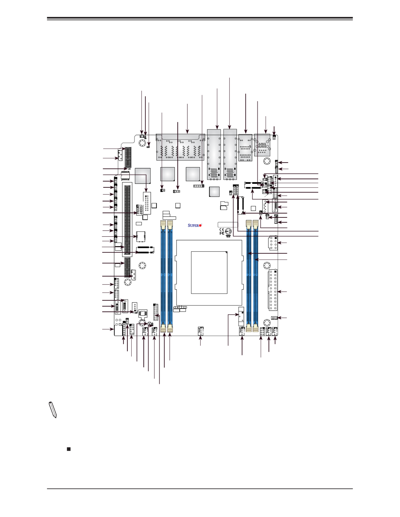
11
Chapter 1: Introduction
7
1
AC
A
PCB EDGE
1
2
3
4
DESIGNED IN USA
BAR CODE
X11SDW-4C-TP13F+
REV:1.00
FAN4 FAN3
FAN1
FAN2
FANB
FANA
JD1
JF1
JSD1
JUSB1
JUSB2
JIPMB1
JNVI2C1
JTGLED1
JTGLED2
JBT1
JTPM1
JPI2C1
JPWR1
J2
JBM1
JBM2
JL1
JLANLED1
S-SGPIO1
JLANLED3
JLANLED2
JSTBY1
LEDT8
LEDT6
LEDM1
LEDT4
LEDT2
JUIDB1
JPG1
J1
JSMB1 JI2C1 JI2C2 JWD1 JPME2
JVRM1
JPL2
JPL3
JPT1
JPUSB1
JPL1
MH1
MH3
MH7
MH2
MH4
MH6
MH5
BT1
JPH1
DIMMB1
DIMMA1
JMD1_SRW2
JMD2_SRW1
JMD1_SRW1
JMD3_SRW1
LED3
LED1
LED2
LEDT7
LEDT5 LEDT1
LEDT3
S-SATA2
S-SATA3
S-SATA1
JSIM1
JGP1
S-SATA0
JPCIE1
JPCIE3
JVGA1
JUSBCOM1
COM2
JRK1
JPW1
JSDP3
JSDP2
JSDP1
JPV1
LAN 1
COM1
USB 4/5(3.0)
USB 2/3
USB 0/1
2-3:DISABLE
1-2:ENABLE
JPT1:TPM
: PCI-E X16+X16
Power LED
JSXB1C
JSXB1B
JSXB1A
CPU
JPL3:
LAN 6/7/8/9
1-2:ENABLE
2-3:DISABLE
JPL2:
2-3:DISABLE
1-2:ENABLE
LAN 2/3/4/5
PCI-E 3.0 X1
JMD3:M.2-P
PCI-E 3.0 X2 / S-SATA4
JMD2:M.2-H
2-3:DISABLE
1-2:ENABLE
JPG1:VGA
JMD1:M.2-H
PCI-E 3.0 X4 / I-SATA4
UID
LAN1
JPL1:
1-2:ENABLE
2-3:DISABLE
LAN 2/3/4/5/6/7/8/9
LAN 12/13 LAN 10/11
IPMI_LAN
2-3:DISABLE
JWD1:W ATCH DOG
1-2:ENABLE
JI2C1/J I2C2:
1-2:RST
2-3:NMI
CHASSIS
JL1:
INTR USION
USB4/5 WAKE UP
JPUSB1:
1-2:ENABLE
2-3:DISABLE
2-3:ME MANUF ACTURING M ODE
JPME2:
1-2:NORMAL
ON
PWR RST X N IC2
FF
OH LED
NIC1 HDD LED
PWR
JF1:
4-7:SPEAKER
1-3:PWR LED
JD1:
DIMME1
DIMMD1
Notes:
• See Chapter 2 for detailed information on jumpers, I/O ports, and JF1 front panel connec-
tions. Jumpers/LED indicators not indicated are used for testing only.
• " " indicates the location of Pin 1.
• When LED1 (Onboard Power LED indicator) is on, system power is on. Unplug the power
cable before installing or removing any components.
Quick Reference
BT1
DIMMB1
DIMMA1
FAN1
JTPM1
JL1
LAN1
IPMI LAN
JPI2C1
DIMME1
DIMMD1
JSIM1
JPME2
JWD1
JGP1
LAN12/13
JBT1
LED3
LED2
JPH1
S-SATA0
LED1
JBM2
FAN2
FAN4
FAN3
UID
S-SATA1
JPG1
JLANLED1
LAN2-9
JBM1
JPV1
JSTBY1
JPWR1
JRK1
JSD1
JMD1
JLANLED2
JLANLED3
JTGLED1
JPL1
JPUSB1
JMD3
JTGLED2
COM1
USB4/5
LAN10/11
JSDP1
JSDP2
JSDP3
JF1
JPL2
JPL3
FANA
FANB
JPT1
JD1
JPW1
USB0/1
USB2/3
JNVI2C1
S-SATA3
S-SATA2
S-SGPIO1
JSXB1C
JMD2
JSXB1B
COM2
JI2C2
JI2C1
JSMB1
JIPMB1
LEDM1
JVGA1
JSXB1A
J1

12
Super X11SDW-4C/14CN/16C-TP13F+ User's Manual
Figure 1-3. X11SDW-TP13F+ Series Motherboard Model Variation Table
X11SDW-TP13F+ Series Motherboard Model Variation Table
Motherboard Model Name X11SDW-4C-
TP13F+
X11SDW-14CN-
TP13F+
X11SDW-16C-
TP13F+
Processor Name D-2123IT D-2177NT D-2183IT
Number of Cores 4 14 16
Number of Threads 8 28 32
Processor Base Frequency 2.20 GHz 1.90 GHz 2.20 GHz
Max Turbo Frequency 3.00 GHz 3.00 GHz 3.00 GHz
SoC Max TDP 60W 105W 100W
Number of Memory Channels 4 4 4
Maximum Memory Speed 2400 MHz 2667 MHz 2400 MHz
Intel® Turbo Boost Technology 2.0 2.0 2.0
Embedded Options Available Yes Yes Yes
Integrated Intel® QuickAssist Technology No Yes No
Intel® Virtualization Technology (VT-x) Yes Yes Yes
Intel® Virtualization Technology for Directed I/O (VT-d) Yes Yes Yes
Intel® TSX-NI Yes Yes Yes
Instruction Set 64-bit 64-bit 64-bit
Instruction Set Extensions Intel® AVX2 AVX2 AVX2Intel® Intel®
Number of AVX-512 FMA Units 1 1 1

13
Chapter 1: Introduction
Quick Reference Table
Jumper Description Default Setting
J1 M.2 SMBus Enable/Disable Pins 1-2 (Enabled)
JBM1 IPMI Share LAN Enable/Disable Open: Enabled (Default)
Closed: Disabled
JBM2 IPMI Dedicated/Share LAN Enable/Disable Open: Enabled (Default)
Closed: Disabled
JBT1 CMOS Clear Open: Normal
Closed: Clear CMOS
JI2C1/JI2C2 SMB to PCIe Slots Enable/Disable Pins 2-3 (Disabled)
JPG1 VGA Enable/Disable Pins 1-2 (Enabled)
JPL1 LAN1 Enable/Disable Pins 1-2 (Enabled)
JPL2 LAN2/3/4/5 Enable/Disable Pins 1-2 (Enabled)
JPL3 LAN6/7/8/9 Enable/Disable Pins 1-2 (Enabled)
JPME2 Manufacturing Mode Select Pins 1-2 (Normal)
JPT1 TPM Enable/Disable Pins 1-2 (Enabled)
JPUSB1 USB0/1 Wake up Pins 1-2 (Enabled)
JWD1 Watch Dog Timer Pins 1-2 (Reset)
LED Description Status
LED1 Power LED Solid Green: Power On
LED2 UID LED Solid Blue: Unit Identied
LED3 Overheat/Power Fail/Fan Fail LED Solid Red: Overheat
Blinking Red: Power Failure/Fan Failure
LEDM1 BMC Heartbeat Blinking Green: BMC Normal
Connector Description
BT1 Onboard Battery
COM1/COM2 COM1: Port, COM2: Header
FAN1 – FAN4, FANA, FANB CPU/System Fan Headers
IPMI LAN Dedicated IPMI LAN Port
JD1 Power LED/Speaker Header (Pins 1–3: Power LED, Pins 4–7: Speaker)
JF1 Front Control Panel Header
JGP1 General Purpose I/O Header
JIPMB1 System Management Bus Header (for IPMI only)
JL1 Chassis Intrusion Header
JLANLED1 LAN1 Activity LED Header
JLANLED2 LAN2-5 Activity LED Header
JLANLED3 LAN6-9 Activity LED Header
JMD1 M.2 Slot M-Key 2280/22110 (SATA3.0 / PCIe x4)
JMD2 M.2 Slot B-Key 2242/3042 (USB2.0 / USB3.0 / SATA3.0 / PCIe x2)

15
Chapter 1: Introduction
Note: The table above is continued on the next page.
Motherboard Features
CPU
• Intel® Xeon D-2100 SoC Series SoC with a TDP of up to 105W
Memory
• Supports up to 256GB of ECC RDIMM or 512GB of ECC LRDIMM DDR4 memory with speeds of up to 2667MHz.
DIMM Size
• Up to 128GB at 1.2V
Expansion Slots
• One M.2 M-Key 2280/22110 (SATA3.0 / PCIe x4)
• One M.2 B-Key 2242/3042 (USB2.0 / USB3.0 / SATA3.0 / PCIe x2)
• One M.2 E-Key Slot 2230 (USB2.0 / PCIe x1)
• One SMC Proprietary WIO-L Slot (JSXB1A, JSXB1B, JSXB1C)
Network
• Intel SoC Integrated 1G and 10G Controller
Baseboard Management Controller (BMC)
• ASpeed AST2500
Graphics
• Graphics controller via ASpeed AST2500
I/O Devices
• SATA 3.0
• Video
• COM Port/Header
• Four S-SATA 3.0 Ports
• One VGA Header
• One COM Port (COM1), one COM Header (COM2)
Peripheral Devices
• Two USB 2.0 Headers (USB0/1, USB2/3)
• Two USB 3.0 Gen 1 Ports (USB4/5)
BIOS
• 256Mb AMI BIOS® SPI Flash BIOS
• Plug and Play (PnP), ACPI 6.1, BIOS rescue hot-key, SMBIOS 2.8/3.1, PCI F/W 3.2, RTC Wakeup, UEFI 2.7
Motherboard Features

16
Super X11SDW-4C/14CN/16C-TP13F+ User's Manual
Motherboard Features
Power Management
• ACPI power management
• CPU fan auto-off in sleep mode
• Power button override mechanism
• Power-on mode for AC power recovery
System Health Monitoring
• Onboard voltage monitors for CPU cores, +1.8V, +3.3V, +5V, +/-12V, +3.3V Stby, +5V Stby, VBAT, HT, Memory, PCH
temperature, system temperature, and memory temperature
• CPU phase switching voltage regulator
• CPU/System overheat control
• CPU Thermal Trip support
Fan Control
• Fan status monitoring with rmware
• Multi-speed fan control via onboard BMC
System Management
• Platform Environment Control Interface (PECI) 3.1 support
• Intel® Node Manager
• IPMI 2.0 with KVM support
• SuperDoctor® 5, Watch Dog, NMI
• Chassis Intrusion header and detection
• Power supply monitoring
LED Indicators
• CPU/System Overheat LED
• Power/Suspend State Indicator LED
• UID/Remote UID
• LAN Activity LED
• Fan Fail LED
• Hdd Activity LED
Other
• RoHS
Dimensions
• Proprietary form factor (8.0" x 9.6") (203.2 mm x 243.84 mm)

17
Chapter 1: Introduction
Note 1: The CPU maximum thermal design power (TDP) is subject to chassis and
heatsink cooling restrictions. For proper thermal management, please check the chas-
sis and heatsink specications for proper CPU TDP sizing.
Note 2: For IPMI conguration instructions, please refer to the Embedded IPMI Con-
guration User's Guide available at http://www.supermicro.com/support/manuals/.
Note 3: If you purchase a Supermicro Out of Band (OOB) software license key
(Supermicro P/N: SFT-OOB--LIC), please do not change the IPMI MAC address. Once
you change the IPMI MAC address, the license will be invalid.
Note 4: Supermicro ships standard products with a unique password for the BMC
ADMIN user. This password can be found on a label on the motherboard. For general
documentation and information on IPMI, please visit our website at https://www.super-
micro.com/en/support/BMC_Unique_Password.

18
Super X11SDW-4C/14CN/16C-TP13F+ User's Manual
Note: This is a general block diagram and may not exactly represent the features on
your motherboard. See the previous pages for the actual specications of your moth-
erboard.
Figure 1-4.
Chipset Block Diagram
eSPI
CPU
U1
SoC
PE1[15:0]
DDR4 DIMM
A1
PE2[15:0]
DDR4 DIMM
B1
DDR4 1866/2133/2400/2666
B
A
DDR4 DIMM
DDR4 DIMM
E
D
KR
PCH
DDR4 1866/2133/2400/2666
SFI
JLAN3
10G PHY
Flexible I/O
6,7
Flexible I/O
16
JPCIE1 SLOT7 PCIE 3.0 x32
PCIE 3.0 x32
Flexible I/O
20~21
Flexible I/O
12~15
Flexible I/O
10
Flexible I/O
11
Flexible I/O
8,9
PCIE 3.0 x2
SATA3.0#0
SATA3.0#1
SATA3.0#2
SATA3.0#3
SATA3.0#4
SATA3.0
USB
M.2 (E-key) CONN(JMD3)
M.2(B-key) CONN(JMD2)
USB 2.0 Header
USB 2.0
USB 2.0 Header
USB2.0 HUB
PCIE 3.0 x2
I350 AM4
I350 AM4
JLAN2
USB 3.0/2.0
USB 3.0 Rear I/O
JTPM1 Header
M.2 (B-key) CONN(JMD2)
USB 3.0
or PCIE 3.0 x2
PCIE 3.0 x1
Flexible I/O
17
PCIE 3.0 x1
I210
JLAN1
Flexible I/O
18~19
Flexible I/O
22~25
PCIE 3.0 x4
M.2 (M-key) CONN(JMD1)
SPI
BMC
AST2500
PCIE 3.0 x1
DDR4
COM1/2
FLASH
M.2 (E-key) CONN(JMD3)
JLAN4
VGA HEADER
PHY
IPMI LAN
JLAN4
D1
E1
TPM
CS4227
CS4227
SFP+
SATA 3.0 (by config)
SFP+

19
Chapter 1: Introduction
1.2 Processor Overview
The Intel Xeon D-2100 series SoC processor family, with up to 16 cores and up to 105W of
power, offers performance, reliability, and high intelligence. As a low-power system-on-a-chip
motherboard, the X11SDW-4C/14CN/16C-TP13F+ is optimized for a variety of workloads that
requires high compute power in a compact form factor.
• ACPI Power Management Logic Support Rev. 4.0a
• Intel Quick Assist Technology
• Intel Turbo Boost Technology
• Adaptive Thermal Management/Monitoring
• PCIe 3.0, SATA 3.0, NVMe
• System Management Bus (SMBus) Specication Version 2.0
• Intel Trusted Execution Technology (Intel TXT)
• Intel Rapid Storage Technology
• Intel Virtualization Technology for Directed I/O (Intel VT-d)
1.3 Special Features
This section describes the health monitoring features of the
X11SDW-4C/14CN/16C-TP13F+ motherboard. The motherboard has an onboard System
Hardware Monitor chip that supports system health monitoring.
Recovery from AC Power Loss
The Basic I/O System (BIOS) provides a setting that determines how the system will respond
when AC power is lost and then restored to the system. You can choose for the system to
remain powered off (in which case you must press the power switch to turn it back on), or
for it to automatically return to the power-on state. See the Advanced BIOS Setup section
for this setting. The default setting is Last State.
20
Super X11SDW-4C/14CN/16C-TP13F+ User's Manual
1.4 System Health Monitoring
The motherboard has an onboard Baseboard Management Controller (BMC) chip that
supports system health monitoring.
Onboard Voltage Monitors
The onboard voltage monitor will continuously scan crucial voltage levels. Once a voltage
becomes unstable, it will give a warning or send an error message to the screen. Users can
adjust the voltage thresholds to dene the sensitivity of the voltage monitor. Real time readings
of these voltage levels are all displayed in IPMI.
Fan Status Monitor with Firmware Control
The system health monitor chip can check the RPM status of a cooling fan. The CPU and
chassis fans are controlled by BIOS Thermal Management through the back panel. Refer
to the below table for available fan modes to choose the most appropriate one for nominal
operation.
Fan Mode Description
Full Speed Use this mode to set fan speed at full speed for maximum system cooling
Standard Use this mode to set fan speed for normal system cooling
Heavy I/O Use this mode to set fan speed for higher PCI-E add-on card area cooling
Optimal Use this mode to set fan speed for normal PCI-E add-on card area cooling
PUE2 Use this mode to set fan speed for best power effi ciency and maximum noise reduction
Figure 1-5. Fan Speed Modes
Environmental Temperature Control
System Health sensors monitor temperatures and voltage settings of onboard processors
and the system in real time via the IPMI interface. Whenever the temperature of the CPU or
the system exceeds a user-dened threshold, system/CPU cooling fans will be turned on to
prevent the CPU or the system from overheating
Note: To avoid possible system overheating, please provide adequate airow to your
system.
System Resource Alert
This feature is available when used with SuperDoctor 5® in the Windows OS or in the Linux
environment. SuperDoctor is used to notify the user of certain system events. For example,
you can congure SuperDoctor to provide you with warnings when the system temperature,
CPU temperatures, voltages and fan speeds go beyond a predened range.

22
Super X11SDW-4C/14CN/16C-TP13F+ User's Manual
Chapter 2
Installation
2.1 Static-Sensitive Devices
Electrostatic Discharge (ESD) can damage electronic com ponents. To prevent damage to your
motherboard, it is important to handle it very carefully. The following measures are generally
sufcient to protect your equipment from ESD.
Precautions
• Use a grounded wrist strap designed to prevent static discharge.
• Touch a grounded metal object before removing the board from the antistatic bag.
• Handle the board by its edges only; do not touch its components, peripheral chips, memory
modules or gold contacts.
• When handling chips or modules, avoid touching their pins.
• Put the motherboard and peripherals back into their antistatic bags when not in use.
• For grounding purposes, make sure your computer chassis provides excellent conductivity
between the power supply, the case, the mounting fasteners and the motherboard.
• Use only the correct type of onboard CMOS battery. Do not install the onboard battery
upside down to avoid possible explosion.
Unpacking
The motherboard is shipped in antistatic packaging to avoid static damage. When unpacking
the motherboard, make sure that the person handling it is static protected.

23
Chapter 2: Installation
7
1
AC
A
PCB EDGE
1
2
3
4
DESIGNED IN USA
BAR CODE
X11SDW-4C-TP13F+
REV:1.00
FAN4 FAN3
N1
FAN2
F
FANA
JD1
JF1
JSD1
JUSB1
JUSB2
JIPMB1
JNVI2C1
JTGLED1
JTGLED2
JBT1
JTPM1
JPI2C1
JPWR1
J2
JBM1
JBM2
JL1
JLANLED1
S-SGPIO1
JLANLED3
JLANLED2
JSTBY1
LEDT8
LEDT6
LEDM1
LEDT4
LEDT2
JUIDB1
JPG1
J1
JSMB1 JI2C1 JI2C2 JWD1 JPME2
JVRM1
JPL2
JPL3
JPT1
SB1
JPL1
MH1
MH3
MH7
MH2
MH4
MH6
MH5
BT1
JPH1
DIMMB1
DIMMA1
JMD1_SRW2
JMD2_SRW1
JMD1_SRW1
JMD3_SRW1
LED3
LED1
LED2
LEDT7
LEDT5 LEDT1
LEDT3
S-SATA2
S-SATA3
S-SATA1
JSIM1
JGP1
S-SATA0
JPCIE1
JPCIE3
JVGA1
JUSBCOM1
COM2
JRK1
JPW1
JSDP3
JSDP2
JSDP1
JPV1
LAN 1
COM1
USB 4/5(3.0)
USB 2/3
USB 0/1
2-3:DISABLE
1-2:ENABLE
JPT1:TPM
: PCI-E X16+X16
Power LED
JSXB1C
JSXB1B
JSXB1A
CPU
JPL3:
LAN 6/7/8/9
1-2:ENABLE
2-3:DISABLE
JPL2:
2-3:DISABLE
1-2:ENABLE
LAN 2/3/4/5
PCI-E 3.0 X1
JMD3:M.2-P
PCI-E 3.0 X2 / S-SATA4
JMD2:M.2-H
2-3:DISABLE
1-2:ENABLE
JPG1:VGA
JMD1:M.2-H
PCI-E 3.0 X4 / I-SATA4
UID
LAN1
JPL1:
1-2:ENABLE
2-3:DISABLE
LAN 2/3/4/5/6/7/8/9
LAN 12/13 LAN 10/11
IPMI_LAN
2-3:DISABLE
JWD1:WATCH DOG
1-2:ENABLE
JI2C1/JI2C2:
1-2:RST
2-3:NMI
CHASSIS
JL1:
INTRUSION
USB4/5 WAKE UP
JPUSB1:
1-2:ENABLE
2-3:DISABLE
2-3:ME MANUFACTURING MODE
JPME2:
1-2:NORMAL
ON
PWR RST X NIC2
FF
OH LED
NIC1 HDD
LED
PWR
JF1:
4-7:SPEAKER
1-3:PWR LED
JD1:
DIMME1
DIMMD1
2.2 Motherboard Installation
All motherboards have standard mounting holes to t different types of chassis. Make sure
that the locations of all the mounting holes for both the motherboard and the chassis match.
Although a chassis may have both plastic and metal mounting fasteners, metal ones are
highly recommended because they ground the motherboard to the chassis. Make sure that
the metal standoffs click in or are screwed in tightly.
Location of Mounting Holes
Note: 1) To avoid damaging the motherboard and its components, please do not use
a force greater than 8 lb/inch on each mounting screw during motherboard installation.
2) Some components are very close to the mounting holes. Please take precautionary
measures to avoid damaging these components when installing the motherboard to
the chassis.
Phillips Screwdriver (1) Standoffs (7)
Only if Needed
Phillips Screws (7)
Tools Needed

24
Super X11SDW-4C/14CN/16C-TP13F+ User's Manual
Installing the Motherboard
1. Locate the mounting holes on the motherboard. See the previous page for the location.
2. Locate the matching mounting holes on the chassis. Align the mounting holes on the
motherboard against the mounting holes on the chassis.
3. Install standoffs in the chassis as needed.
4. Install the motherboard into the chassis carefully to avoid damaging other motherboard
components.
5. Using the Phillips screwdriver, insert a Phillips head #6 screw into a mounting hole on
the motherboard and its matching mounting hole on the chassis.
6. Repeat Step 5 to insert #6 screws into all mounting holes.
7. Make sure that the motherboard is securely placed in the chassis.
Note: Images displayed are for illustration only. Your chassis or components might
look different from those shown in this manual.
Termékspecifikációk
| Márka: | Supermicro |
| Kategória: | alaplap |
| Modell: | X11SDW-14CN-TP13F+ |
Szüksége van segítségre?
Ha segítségre van szüksége Supermicro X11SDW-14CN-TP13F+, tegyen fel kérdést alább, és más felhasználók válaszolnak Önnek
Útmutatók alaplap Supermicro

19 December 2024
5 December 2024
3 Szeptember 2024
2 Szeptember 2024
2 Szeptember 2024
2 Szeptember 2024
2 Szeptember 2024
2 Szeptember 2024
2 Szeptember 2024
2 Szeptember 2024
Útmutatók alaplap
- alaplap Sharkoon
- alaplap Gigabyte
- alaplap Asus
- alaplap Biostar
- alaplap Asrock
- alaplap MSI
- alaplap NZXT
- alaplap ECS
- alaplap Evga
- alaplap Intel
- alaplap Foxconn
- alaplap Advantech
- alaplap Elitegroup
- alaplap EPoX
Legújabb útmutatók alaplap

9 Április 2025
9 Április 2025
3 Április 2025
3 Április 2025
3 Április 2025
3 Április 2025
2 Április 2025
2 Április 2025
31 Március 2025
27 Március 2025