Használati útmutató Supermicro CSE-847E16-RJBOD1
Supermicro
Számítógép behuzás
CSE-847E16-RJBOD1
Olvassa el alább 📖 a magyar nyelvű használati útmutatót Supermicro CSE-847E16-RJBOD1 (128 oldal) a Számítógép behuzás kategóriában. Ezt az útmutatót 4 ember találta hasznosnak és 2 felhasználó értékelte átlagosan 4.5 csillagra
Oldal 1/128

SC847 CHASSIS SERIES
USER’S MANUAL
1.0b
SUPER ®
SC847A-R1400LPB SC847A-R1400UB
SC847E1-R1400LPB SC847E1-R1400UB
SC847E2-R1400LPB SC847E2-R1400UB
SC847E16-R1400LPB SC847E16-R1400UB
SC847E26-R1400LPB SC847E26-R1400UB

SC847 Chassis Manual
ii
Manual Revision 1.0b
Release Date: April 23, 2010
The information in this User’s Manual has been carefully reviewed and is believed to be accurate.
The vendor assumes no responsibility for any inaccuracies that may be contained in this document,
makes no commitment to update or to keep current the information in this manual, or to notify any
person or organization of the updates. Please Note: For the most up-to-date version of this
manual, please see our web site at www.supermicro.com.
Super Micro Computer, Inc. ("Supermicro") reserves the right to make changes to the product
described in this manual at any time and without notice. This product, including software and
documentation, is the property of Supermicro and/or its licensors, and is supplied only under a
license. Any use or reproduction of this product is not allowed, except as expressly permitted by
the terms of said license.
IN NO EVENT WILL SUPERMICRO BE LIABLE FOR DIRECT, INDIRECT, SPECIAL, INCIDENTAL,
SPECULATIVE OR CONSEQUENTIAL DAMAGES ARISING FROM THE USE OR INABILITY TO
USE THIS PRODUCT OR DOCUMENTATION, EVEN IF ADVISED OF THE POSSIBILITY OF
SUCH DAMAGES. IN PARTICULAR, SUPERMICRO SHALL NOT HAVE LIABILITY FOR ANY
HARDWARE, SOFTWARE, OR DATA STORED OR USED WITH THE PRODUCT, INCLUDING THE
COSTS OF REPAIRING, REPLACING, INTEGRATING, INSTALLING OR RECOVERING SUCH
HARDWARE, SOFTWARE, OR DATA.
Any disputes arising between manufacturer and customer shall be governed by the laws of Santa
Clara County in the State of California, USA. The State of California, County of Santa Clara shall
be the exclusive venue for the resolution of any such disputes. Super Micro's total liability for all
claims will not exceed the price paid for the hardware product.
California Best Management Practices Regulations for Perchlorate Materials: This Perchlorate
warning applies only to products containing CR (Manganese Dioxide) Lithium coin cells. “Perchlorate
Material-special handling may apply. See www.dtsc.ca.gov/hazardouswaste/perchlorate”
WARNING: Handling of lead solder materials used in this
product may expose you to lead, a chemical known to
the State of California to cause birth defects and other
reproductive harm.
Unless you request and receive written permission from Super Micro Computer, Inc., you may not
copy any part of this document.
Information in this document is subject to change without notice. Other products and companies
referred to herein are trademarks or registered trademarks of their respective companies or mark
holders.
Copyright © 2010 by Super Micro Computer, Inc.
All rights reserved.
Printed in the United States of America

iii
Preface
Preface
About This Manual
This manual is written for professional system integrators and PC technicians. It
provides information for the installation and use of the SC847 chassis. Installation
and maintenance should be performed by experienced technicians only.
This manual lists compatible parts available when this document was published. Al-
ways refer to the our Web site for updates on supported parts and congurations.

SC847 Chassis Manual
iv
Manual Organization
Chapter 1: Introduction
The rst chapter provides a checklist of the main components included with this
chassis and describes the main features of the SC847 chassis. This chapter also
includes contact information.
Chapter 2: System Safety
This chapter lists warnings, precautions, and system safety. It is recommended that
you thoroughly familiarize yourself with installing and servicing the chassis and all
safety precautions.
Chapter 3: Chassis Components
Refer here for details on this chassis components including the fans, hard drives,
air shrouds, and other components.
Chapter 4: System Interface
Refer to this chapter for details on the system interface, which includes the func-
tions and information provided by the chassis control panel, as well as other LEDs
located throughout the system.
Chapter 5: Chassis Setup and Maintenance
Follow the procedures given in this chapter when installing, removing, or
reconguring components in your chassis.
Chapter 6: Rack Installation
Refer to this chapter for detailed information on chassis rack installation. You should
follow the procedures given in this chapter when installing, removing or reconguring
your chassis into a rack environment.

v
Preface
This section lists compatible cables, power supply specications, and compatible
backplanes. Not all compatible backplanes are listed. Refer to our Web site for the
latest compatible backplane information.
Appendix A: Hardware
This section provides information on cabling, and other hardware which is compat-
ible with your chassis. For complete information on supported cables and hardware,
refer to the Supermico Web site at www.supermicro.com.
Appendix B: Power Supply Specications
This chapter lists the specications of the power supply provided with your chas-
sis. For additional information, refer to the Supermicro website at www.supermicro.
com.
Appendix C: SAS-826A Backplane Specications
This section contains detailed specications on the SC826A backplane. Additional
information can be found on the Supermicro Web site at www.supermicro.com.
Appendix D: SAS-846A Backplane Specications
This chapter contains information on the SC846A backplane. Additional information
can be found on the Supermicro Web site at www.supermicro.com.
Appendix E: SAS-826EL Backplane Specications
This section contains detailed specications for the SC826EL backplane. Additional
information can be found on the Supermicro Web site at www.supermicro.com.
Appendix F: SAS-846EL Backplane Specications
This chapter contains specications on the SC846EL backplane. Additional informa-
tion can be found on the Supermicro Web site at www.supermicro.com.

SC847 Chassis Manual
vi
Table of Contents
Chapter 1 Introduction
1-1 Overview ......................................................................................................... 1-1
1-2 Shipping List .................................................................................................... 1-1
1-3 Where to get Replacement Components ........................................................ 1-2
1-4 Contacting Supermicro .................................................................................... 1-3
1-5 Returning Merchandise for Service................................................................. 1-4
Chapter 2 System Safety
2-1 Overview ......................................................................................................... 2-1
2-2 Warnings and Precautions .............................................................................. 2-1
2-3 Preparing for Setup ......................................................................................... 2-1
2-4 Electrical Safety Precautions .......................................................................... 2-2
2-5 General Safety Precautions ............................................................................ 2-3
2-6 System Safety ................................................................................................. 2-3
Chapter 3 System Interface
3-1 Overview ......................................................................................................... 3-1
3-2 Control Panel Buttons ..................................................................................... 3-2
3-3 Control Panel LEDs ........................................................................................ 3-2
3-4 Drive Carrier LEDs .......................................................................................... 3-4
SAS/SATA Drives ............................................................................................ 3-4
SCSI Drives ..................................................................................................... 3-4
Chapter 4 Chassis Setup and Maintenance
4-1 Overview ......................................................................................................... 4-1
4-2 Removing the Chassis Cover ......................................................................... 4-2
4-3 Installing Removable Hard Drives................................................................... 4-3
4-4 Installing Optional Fixed Hard Drives ............................................................. 4-6
4-5 Installing the Motherboard .............................................................................. 4-9
Permanent and Optional Standoffs ................................................................. 4-9
Add-on Card/Expansion Slot Setup .............................................................. 4-10
Expansion Slot Setup in LP (Low Prole) Chassis ....................................... 4-10
Expansion Slot Setup in U (Universal Output) Chassis ................................4-11
4-6 Installing the Air Shroud ................................................................................ 4-12
4-7 Checking the Server's Air Flow ..................................................................... 4-13
4-8 System Fans ................................................................................................. 4-14

vii
Preface
4-9 Power Supply ............................................................................................... 4-1 6
Chapter 5 Cascading Congurations
5-1 Cascading Conguration Overview ................................................................. 5-1
5-2 Parallel Connectivity for Performance............................................................. 5-1
5-3 Parallel Connectivity for Performance with Mutiple PCI Buses ...................... 5-2
5-4 Serial Connectivity for Increased Capacity ..................................................... 5-3
5-5 Serial Connectivity for Increased Capacity ..................................................... 5-4
5-6 Serial Connectivity for Redundancy ................................................................ 5-5
5-6 Serial Connectivity for Redundancy and Performance w/Multiple PCI Buses 5-6
5-6 Supported Cascading Conguration Cabling .................................................. 5-7
Chapter 6 Rack Installation
6-1 Overview ......................................................................................................... 6-1
6-2 Unpacking the System .................................................................................... 6-1
6-3 Preparing for Setup ......................................................................................... 6-1
Choosing a Setup Location ............................................................................. 6-1
6-4 Warnings and Precautions .............................................................................. 6-2
Rack Precautions ............................................................................................ 6-2
General Server Precautions ............................................................................ 6-2
6-5 Rack Mounting Considerations ....................................................................... 6-3
Ambient Operating Temperature ..................................................................... 6-3
Reduced Airow .............................................................................................. 6-3
Mechanical Loading ........................................................................................ 6-3
Circuit Overloading .......................................................................................... 6-3
Reliable Ground .............................................................................................. 6-3
6-6 Rack Mounting Instructions ............................................................................. 6-4
Identifying the Sections of the Rack Rails ...................................................... 6-4
Locking Tabs ................................................................................................... 6-5
Releasing the Inner Rail ................................................................................. 6-5
Installing The Inner Rails on the Chassis ....................................................... 6-6
Installing the Outer Rails on the Rack ............................................................ 6-7
Standard Chassis Installation ......................................................................... 6-8
Optional Quick Installation Method ................................................................. 6-9
Adapters for Round and Threaded Hole Racks ........................................... 6-10

SC847 Chassis Manual
viii
Appendix A SC847 Cables and Hardware
Appendix B SC847 Power Supply Specications
Appendix C SAS-826A Backplane Specications
Appendix D SAS-846A Backplane Specications
Appendix E SAS-826EL Backplane Specications
Appendix F SAS-846EL Backplane Specications

Chapter 1
Introduction
1-1 Overview
Optimized for enterprise-level heavy-capacity storage applications, Supermicro's
SC847 chassis features 36x (24 front + 12 rear) 3.5" hot-swap HDD bays used as a
server chassis. The SC847 design provides high-density storage in a 4U form factor,
with high power efciency, optimized HDD signal trace routing and improved HDD
carrier design to dampen vibration and maximize performance. Equipped with a
1400W (Gold Level) high-efciency redundant power supply and ve hot-plug redun-
dant cooling fans, the SC847 is a reliable, high-quality storage workhorse system.
1-2 Shipping List
Please visit the following link for the latest shiping lists and part numbers for your
particular chassis model http://www.supermicro.com/
Chapter 1: Introduction
1-1
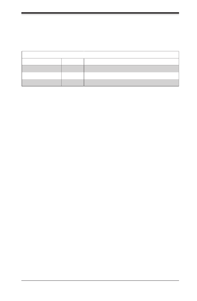
SC847 Chassis
Model CPU HDD I/O
Slots
Power
Supply
SC847A-R1400LPB DP/UP 36x (Server) SAS/
SATA 7x LP 1400W redundant
(Gold Level)
SC847A-R1400UB DP/UP 36x (Server) SAS/
SATA
4x FF + 3
LP (UIO)
1400W redundant
(Gold Level)
SC847E1-R1400LPB DP/UP 36x (Server) SAS/
SATA 7x LP 1400W redundant
(Gold Level)
SC847E1-R1400UB DP/UP 36x (Server) SAS/
SATA
4x FF + 3
LP (UIO)
1400W redundant
(Gold Level)
SC847E2-R1400LPB DP/UP 36x (Server) SAS/
SATA support 7x LP 1400W redundant
(Gold Level)
SC847E2-R1400UB DP/UP 36x (Server) SAS/
SATA support
4x FF + 3
LP (UIO)
1400W redundant
(Gold Level)
SC847E26-R1400LPB DP/UP 36x (Server) SAS/
SATA SAS2 support 7x LP 1400W redundant
(Gold Level)
SC847E26-R1400UB DP/UP 36x (Server) SAS/
SATA SAS2 support
4x FF + 3
LP (UIO)
1400W redundant
(Gold Level)

SC847 Chassis Manual
1-2
1-3 Where to get Replacement Components
Though not frequently, you may need replacement parts for your system. To en-
sure the highest level of professional service and technical support, we strongly
recommend purchasing exclusively from our Supermicro Authorized Distributors/
System Integrators/Resellers. A list of Supermicro Authorized Distributors/System
Integrators/Resellers can be found at: http://www.supermicro.com. Click the Where
to Buy link.

1-3
Chapter 1: Introduction
1-4 Contacting Supermicro
Headquarters
Address: Super Micro Computer, Inc.
980 Rock Ave.
San Jose, CA 95131 U.S.A.
Tel: +1 (408) 503-8000
Fax: +1 (408) 503-8008
Email: marketing@supermicro.com (General Information)
support@supermicro.com (Technical Support)
Web Site: www.supermicro.com
Europe
Address: Super Micro Computer B.V.
Het Sterrenbeeld 28, 5215 ML
's-Hertogenbosch, The Netherlands
Tel: +31 (0) 73-6400390
Fax: +31 (0) 73-6416525
Email: sales@supermicro.nl (General Information)
support@supermicro.nl (Technical Support)
rma@supermicro.nl (Customer Support)
Asia-Pacic
Address: Super Micro Computer, Inc.
4F, No. 232-1, Liancheng Rd.
Chung-Ho 235, Taipei County
Taiwan, R.O.C.
Tel: +886-(2) 8226-3990
Fax: +886-(2) 8226-3991
Web Site: www.supermicro.com.tw
Technical Support:
Email: support@supermicro.com.tw
Tel: 886-2-8226-1900

SC847 Chassis Manual
1-4
1-5 Returning Merchandise for Service
A receipt or copy of your invoice marked with the date of purchase is required be-
fore any warranty service will be rendered. You can obtain service by calling your
vendor for a Returned Merchandise Authorization (RMA) number. When returning
to the manufacturer, the RMA number should be prominently displayed on the
outside of the shipping carton, and mailed prepaid or hand-carried. Shipping and
handling charges will be applied for all orders that must be mailed when service
is complete.
For faster service, RMA authorizations may be requested online (http://www.
supermicro.com/support/rma/).
Whenever possible, repack the chassis in the original Supermicro carton, using the
original packaging material. If these are no longer available, be sure to pack the
chassis securely, using packaging material to surround the chassis so that it does
not shift within the carton and become damaged during shipping.
This warranty only covers normal consumer use and does not cover damages in-
curred in shipping or from failure due to the alteration, misuse, abuse or improper
maintenance of products.
During the warranty period, contact your distributor rst for any product problems.

2-1
Chapter 2: System Safety
Chapter 2
System Safety
2-1 Overview
This chapter provides a quick setup checklist to get your chassis up and running.
Following the steps in order given should enable you to have your chassis set up
and operational within a minimal amount of time. This quick setup assumes that you
are an experienced technician, famailiar with common concepts and terminology.
2-2 Warnings and Precautions
You should inspect the box the chassis was shipped in and note if it was damaged
in any way. If the chassis itself shows damage, le a damage claim with carrier
who delivered your system.
Decide on a suitable location for the rack unit that will hold that chassis. It should
be situated in a clean, dust-free area that is well venilated. Avoid areas where heat,
electrical noise and eletromagnetic elds are generated.
You will also need the system placed near at least one grounded power outlet. When
congured, the SC847 chassis includes one power supply. "R" models include a
redundant power supply and require two grounded outlets.
2-3 Preparing for Setup
The SC847 chassis includes a set of rail assemblies which includes mounting brack-
ets and mounting screws you will need to install the systems into the rack. Please
read this manual in its entirety before you begin the installation procedure.

SC847 Chassis Manual
2-2
2-4 Electrical Safety Precautions
Basic electrical safety precautions should be followed to protect yourself from harm
and the SC847 from damage:
Be aware of the locations of the power on/off switch on the chassis as well •
as the room’s emergency power-off switch, disconnection switch or electrical
outlet. If an electrical accident occurs, you can then quickly remove power from
the system.
Do not work alone when working with high voltage components.•
Power should always be disconnected from the system when removing or install-•
ing main system components, such as the serverboard, memory modules (not
necessary for hot swappable drives). When disconnecting power, you should rst
power down the system with the operating system and then unplug the power
cords from all the power supply modules in the system.
When working around exposed electrical circuits, another person who is fa-•
miliar with the power-off controls should be nearby to switch off the power, if
necessary.
Use only one hand when working with powered-on electrical equipment. This •
is to avoid making a complete circuit, which will cause electrical shock. Use
extreme caution when using metal tools, which can easily damage any electrical
components or circuit boards they come into contact with.
Do not use mats designed to decrease electrostatic discharge as protection from •
electrical shock. Instead, use rubber mats that have been specically designed
as electrical insulators.
The power supply power cord must include a grounding plug and must be •
plugged into grounded electrical outlets.
Serverboard battery: CAUTION - There is a danger of explosion if the onboard •
battery is installed upside down, which will reverse its polarities This battery
must be replaced only with the same or an equivalent type recommended by
the manufacturer. Dispose of used batteries according to the manufacturer’s
instructions.

2-3
Chapter 2: System Safety
Please handle used batteries carefully. Do not damage the battery in any way; •
a damaged battery may release hazardous materials into the environment. Do
not discard a used battery in the garbage or a public landll. Please comply
with the regulations set up by your local hazardous waste management agency
to dispose of your used battery properly.
2-5 General Safety Precautions
Keep the area around the chassis clean and free of clutter.•
Place the chassis top cover and any system components that have been re-•
moved away from the system or on a table so that they won’t accidentally be
stepped on.
While working on the system, do not wear loose clothing such as neckties and •
unbuttoned shirt sleeves, which can come into contact with electrical circuits or
be pulled into a cooling fan.
Remove any jewelry or metal objects from your body, which are excellent metal •
conductors that can create short circuits and harm you if they come into contact
with printed circuit boards or areas where power is present.
After accessing the inside of the system, close the system back up and secure •
it to the rack unit with the retention screws after ensuring that all connections
have been made.
2-6 System Safety
Electrostatic discharge (ESD) is generated by two objects with different electrical
charges coming into contact with each other. An electrical discharge is created to
neutralize this difference, which can damage electronic components and printed
circuit boards. The following measures are generally sufcient to neutralize this
difference before contact is made to protect your equipment from ESD:
Do not use mats designed to decrease electrostatic discharge as protection from •
electrical shock. Instead, use rubber mats that have been specically designed
as electrical insulators.
Use a grounded wrist strap designed to prevent static discharge.•
Keep all components and printed circuit boards (PCBs) in their antistatic bags •
until ready for use.

SC847 Chassis Manual
2-4
Touch a grounded metal object before removing any board from its antistatic •
bag.
Do not let components or PCBs come into contact with your clothing, which may •
retain a charge even if you are wearing a wrist strap.
Handle a board by its edges only; do not touch its components, peripheral chips, •
memory modules or contacts.
When handling chips or modules, avoid touching their pins.•
Put the serverboard and peripherals back into their antistatic bags when not •
in use.
For grounding purposes, make sure your computer chassis provides excellent •
conductivity between the power supply, the case, the mounting fasteners and
the serverboard.

3-1
Chapter 3: System Interface
Chapter 3
System Interface
3-1 Overview
There are several LEDs on the control panel as well as others on the drive carriers
to keep you constantly informed of the overall status of the system as well as the
activity and health of specic components. Most SC847 models have two buttons
on the chassis control panel: A reset button and a power on/off switch. This chapter
explains the meanings of all LED indicators and the appropriate responses you
may need to take.
Figure 3-1: Control Panel

SC847 Chassis Manual
3-2
3-3 Control Panel LEDs
The control panel located on the left handle of the SC847 chassis has ve LEDs.
These LEDs provide you with critical information related to different parts of the
system. This section explains what each LED indicates when illuminated and any
corrective action you may need to take.
Power: The main power button is used to apply or remove power from the power
supply to the server system. Turning off system power with this button removes
the main power but keeps standby power supplied to the system. Therefore, you
must unplug system before servicing.
3-2 Control Panel Buttons
There are two push-buttons located on the left handle of the chassis. These are
(in order from top to bottom) a power on/off button and a reset button.
Power: Indicates power is being supplied to the system's power supply units. This
LED should normally be illuminated when the system is operating.
HDD: Indicates IDE channel activity. SAS/SATA drive, and/or DVD-ROM drive
activity when ashing.
Reset: The reset button is used to reboot the system.
3-3
Chapter 3: System Interface
NIC1: Indicates network activity on GLAN1 when ashing.
NIC2: Indicates network activity on GLAN2 when ashing.
1
2
!
Power Failure: When this LED ashes, it indicates a failure in the redundant power
supply.
Overheat /Fan Fail: -When this LED ashes, it indicates a fan failure. When con
tinuously on (not ashing) it indicates an overheat condition, which may be caused
by cables obstructing the airow in the system or the ambient room temperature
being too warm. Check the routing of the cables and make sure all fans are pres-
ent and operating normally. You should also check to make sure that the chassis
covers are installed. Finally, verify that the heatsinks are installed properly. This
LED will remain ashing or on as long as the overheat condition exists.

SC847 Chassis Manual
3-4
3-4 Drive Carrier LEDs
The SC847 chassis uses SAS or SATA drives.
SAS/SATA Drives
Each SAS/SATA drive carrier has two LEDs.
Blue:•
Solid on = Drive is present and available.
Blinking = Drive is actively being accessed.
Each Serial ATA drive carrier has a blue LED. When illuminated in a solid
on state, this blue LED (on the front of the SAS/SATA drive carrier) indicates
drive activity. A connection to the SAS/SATA backplane enables this LED to
blink on and off when that particular drive is being accessed.
Red:•
Solid on = Drive failure
Blinking = RAID activity
When the red LED is blinking, it indicates that the system is either building,
initializing or rebuilding RAID.
SCSI Drives
This chassis does not support SCSI drives at this time.

4-1
Chapter 4: Chassis Setup and Maintenance
Chapter 4
Chassis Setup and Maintenance
4-1 Overview
This chapter covers the steps required to install components and perform mainte-
nance on the chassis. The only tool you will need to install components and perform
maintenance is a Phillips screwdriver. Print this chapter to use as a reference while
setting up your chassis.
Review the warnings and precautions listed in the manual before
setting up or servicing this chassis. These include information in
Chapter 2: System Safety and the warnings/precautions listed in the
setup instructions.
Safety Warning: Before performing any chassis setup or mainte-
nance, it is recommended that the chassis be removed from the rack
and placed on a stable bench or table. For instructions on how to
uninstall the chassis from the rack, refer to Chapter 5 Rack Instal-
lation in this manual.
!
!

SC847 Chassis Manual
4-2
4-2 Removing the Chassis Cover
Figure 4-1: Removing the Chassis Cover
2
1
2
1
2
2
3
Removing the Chassis Cover
Unplug the chassis from any power source1.
Remove the screws securing the cover to the chassis.2.
Lift the cover up and off the chassis.3.
Warning: Except for short periods of time, do NOT operate the
server without the cover in place. The chassis cover must be in
place to allow proper airow and prevent overheating.
!
4-3
Chapter 4: Chassis Setup and Maintenance
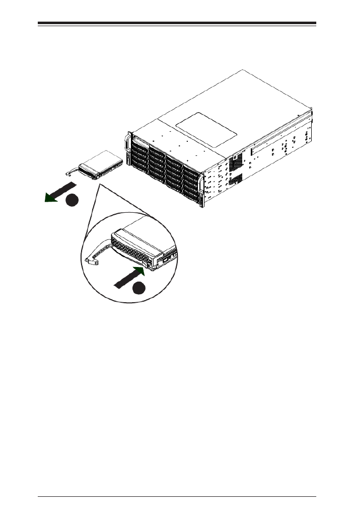
4-3 Installing Removable Hard Drives
Removing Hard Drive Carriers from the Chassis
Press the release button on the drive carrier. This extends the drive carrier 1.
handle.
Use the handle to pull the drive carrier out of the chassis.2.
Figure 4-2: Removing Hard Drive
2
1

SC847 Chassis Manual
4-4
The drives are mounted in drive carriers to simplify their installation and removal
from the chassis. These carriers also help to promote proper airow for the drive
bays.
Figure 4-3: Chassis Drive Carrier
Installing a Hard Drive to the Hard Drive Carrier
Remove the two screws securing the dummy drive to the drive carrier and 1.
remove the dummy drive. Place the hard drive carrier on a at surface such
as a desk, table or work bench.
Warning: Except for short periods of time (while swapping hard
drives), do not operate the server with the drives removed from
the chassis drive bays.
Figure 4-4: Removing the Dummy Drive from the Carrier
Drive Carrier Dummy Drive
!
1
1
Warning! Enterprise level hard disk drives are recommended
for use in Supermicro chassis and servers. For information on
recommended HDDs, visit the Supermicro Web site at http://
www.supermicro.com/products/nfo/les/storage/SAS-1-Com-
pList-110909.pdf
!

4-5
Chapter 4: Chassis Setup and Maintenance
Slide the hard drive into the carrier with the printed circuit board side facing 2.
down.
Carefully align the mounting holes in both the drive carrier and the hard drive.3.
Secure the hard drive to the carrier using six screws.4.
Replace the drive tray into the chassis. Make sure to close the drive carrier 5.
handle to lock the drive carrier into place.
Drive Carrier
SAS/SATA
Hard Drive
Figure 4-5: Installing the Hard Drive into the Carrier
Figure 4-6: Installing the Hard Drive
4
4
5
SC847 Chassis Manual
4-6
4-4 Installing Optional Fixed Hard Drives
The SC847 chassis includes brackets for installing either one 3.5" xed hard drive,
or two 2.5" xed hard drives within the chassis. Each chassis can accomodate up
to two internal drive trays supporting up to two 3.5" hard drives or up to four 2.5"
hard drives. The tray part number is MCP-220-84701-0N.
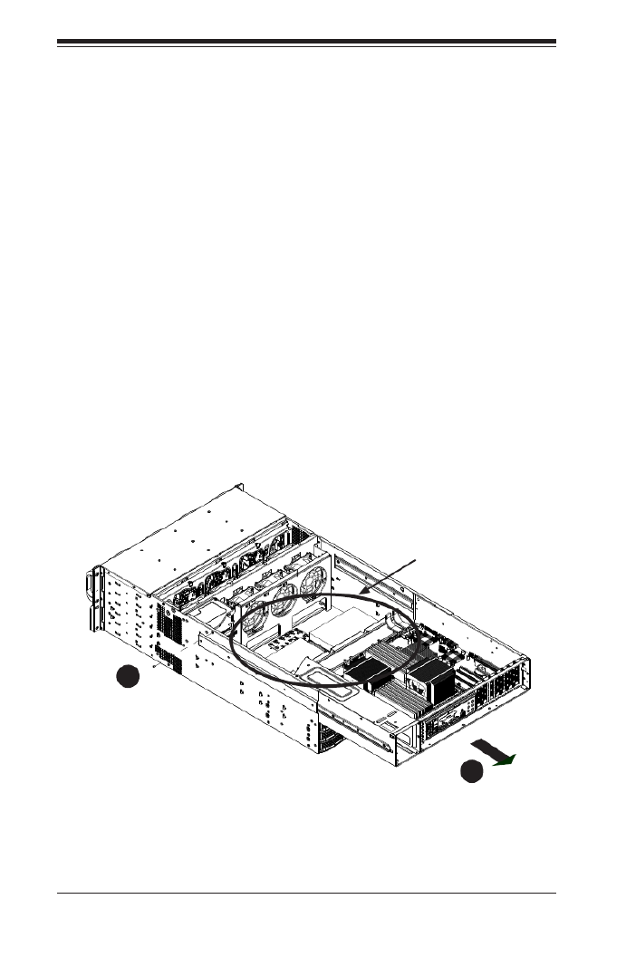
Installing Fixed HDDs into the SC847 Chassis
Disconnect the chassis from any power source. 1.
Remove the chassis cover as described in Section 4-2. 2.
Remove the screw securing the motherboard node tray to the chassis.3.
Slide back the motherboard node tray to reveal the HDD mounting location on 4.
the oor of the chassis.
1
4
1
3
Fixed HDD
Mounting
Location
Figure 4-7: Sliding Back the Motherboard Node Tray
4-7
Chapter 4: Chassis Setup and Maintenance
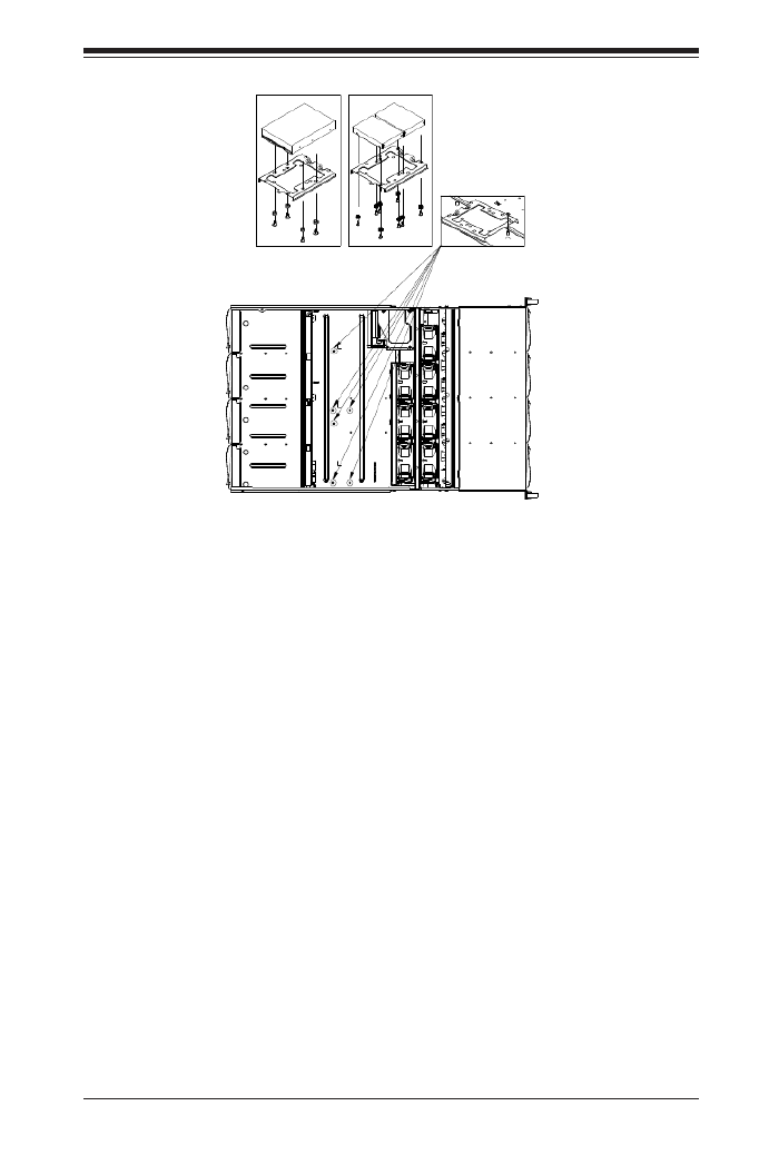
Installing a 3.5" Single Hard Drive into the Bracket
Align the four round washers and four screws with the holes in the hard drive 1.
and the holes in the bracket.
Secure the hard drive to the bracket using the screws and washers provided.2.
See the instructions below for installing the bracket onto the chassis.3.
Installing Dual 2.5" Hard Drives into the Bracket
Align the eight external tooth washers and eight screws with the holes in the 1.
hard drive and the holes in the bracket.
Secure the hard drive to the bracket using the screws and washers provided.2.
See the instructions below for installing the bracket onto the chassis.3.
Installing the Bracket onto the Chassis
Align the holes in the bracket with the chassis standoffs. 1.
Secure the bracket using the screw provided as shown in Figure 4-10.2.
Figure 4-8: Installing Single and Dual Hard Drives and the Bracket

SC847 Chassis Manual
4-8
Lay the motherboard on the chassis aligning the permanent and optional 4.
standoffs
Secure the motherboard to the chassis using the rounded, Phillips head 5.
screws. Do not exceed eight pounds of torque per square inch when tighten-
ing down the motherboard.
Secure the CPU(s), heatsinks, and other components to the motherboard as 6.
described in the motherboard documentation.
Slide back the motherboard tray and connect the cables between the moth-7.
erboard, backplane, chassis, front panel, and power supply, as needed. The
fans may be temporarily removed to allow access to the backplane ports.
Figure 4-9: Motherboard Installation
Figure 4-10: Slide Back the Motherboard Tray
1
7
1
5

4-9
Chapter 4: Chassis Setup and Maintenance
4-5 Installing the Motherboard
Installing the Motherboard
Review the documentation that came with your motherboard. Become familiar 1.
with component placement, requirements, precautions, and cable connec-
tions.
Open the chassis cover and remove the chassis from any power source.2.
As required by your motherboard, install standoffs in any areas that do not 3.
have a permanent standoff. To do this:
A. Place a hexagonal standoff screw through the bottom the chassis.
B. Secure the screw with the hexagon nut (rounded side up).
Figure 4-11: Chassis Standoffs
Permanent and Optional Standoffs
Standoffs prevent short circuits by securing space between the motherboard and
the chassis surface. The SC847 chassis includes permanent standoffs in locations
used by most motherboards. These standoffs accept the rounded Phillips head
screws included in the SC847 accessories packaging.
Some motherboards require additional screws for heatsinks, general components
and/or non-standard security. Optional standoffs are included to these mother-
boards. To use an optional standoff, you must place the hexagonal screw through
the bottom the chassis and secure the screw with the hexagon nut (rounded side
up).
Pan head
6-32 x 5 mm
Flat head
6-32 x 5 mm
M/B standoff
6-32 to 6-32

SC847 Chassis Manual
4-10
Add-on Card/Expansion Slot Setup
SC847: The chassis includes I/O slots for expansion cards. The number of cards
used depends on your chassis model.
SC847 LP Models: Provides seven low-prole expansion card slots.
SC847 UIO Models: Provides three full-height/full-length slots, three low-prole
slots and includes a universal expansion card.
Figure 4-12: SC825 LP model
Expansion Slot Setup in LP (Low Prole) Chassis
SC847 chassis include slots for expansion cards. The number of cards you can use
depends on your chassis model and motherboard model.
Installing Expansion cards in SC847 LP (Low Prole) Chassis
Disconnect the power supply, lay the chassis on a at surface, and open the 1.
chassis cover.
Remove the screw holding the cover in place for each low prole expansion 2.
card slot you want to use. Keep this screw for later use.
Connect the expansion cards to the motherboard.3.
Secure each card to the chassis using the card's L-bracket and the screw 4.
previously removed.
Expansion
Card Slots

4-11
Chapter 4: Chassis Setup and Maintenance
Expansion Slot Setup in U (Universal Output) Chassis
SC847 U model chassis accepts a slightly smaller "L" shaped motherboard to allow
for a universal expansion card. This universal output card allows the systems to
accept SAS, SCSI, IB, Ethernet, and other types of connections.
SC847 U chassis accepts three full-length, full-height add-on cards and the fourth
slot is used for the UI/O card. It includes a bracket that extends from the fan row to
the back of the chassis. This bracket provides support for the riser card.
Installing a Universal Input/Output Card in the SC847 U Model Chassis
Disconnect the power supply, lay the chassis on a at surface, and open the 1.
chassis cover.
Connect the universal input/output to the motherboard using the slots pro-2.
vided on the motherboard and the back panel.
Secure the card to the chassis using the four screws provided in the chassis 3.
packaging.
The SC847 U model chassis includes three full-height/full-length slots and three
low-prole slots.
Installing Expansion Cards in the SC847 U Chassis
Disconnect the power supply, lay the chassis on a at surface, and open the 1.
chassis cover.
If you are using a universal input/output card, make sure it is installed before 2.
continuing.
If you installing low prole add-on cards, remove the chassis air shroud.3.
Secure the card to the chassis using the four screws provided with the chas-4.
sis packaging.

SC847 Chassis Manual
4-12
4-6 Installing the Air Shroud
Air shrouds concentrate airow to maximize fan efciency. The SC847 chassis air
shroud does not require screws for its installation. The SC847 air shroud is designed
with removeable break-away tabs that allow the air shroud to be adjusted to t a
variety of motherboards.
Installing the Air Shroud
Disconnect the chassis from any power source and remove the chassis cover.1.
Place the air shroud in the chassis. The air shroud ts behind the fans and 2.
beside to the power supply.
After checking the t of the air shroud, remove any break-away tabs neces-3.
sary to ensure a proper t with the motherboard.
Figure 4-13: Air Shroud for SC847LP Chassis

4-13
Chapter 4: Chassis Setup and Maintenance
4-7 Checking the Server's Air Flow
Checking the Air Flow
1. Make sure there are no objects to obstruct airow in and out of the server. In
addition, if you are using a front bezel, make sure the bezel's lter is replaced
periodically.
2. Do not operate the server without drives or drive trays in the drive bays. Use
only recommended server parts.
3. Make sure no wires or foreign objects obstruct air ow through the chassis. Pull
all excess cabling out of the airow path or use shorter cables.
The control panel LEDs inform you of system status. See “Chapter 3: System
Interface” for details on the LEDs and the control panel buttons.
In most cases, the chassis power supply and fans are pre-installed. If you need to
install fans continue to the Systems Fan section of this chapter. If the chassis will be
installed into a rack, continue to the next chapter for rack installation instructions

SC847 Chassis Manual
4-14
Seven hot-swappable, heavy-duty fans provide cooling for the chassis. These fans
circulate air through the chassis thereby lowering the chassis internal tempera-
ture.
4-8 System Fans
Replacing a System Fan
Open the chassis while the power is running to determine which fan has 1.
failed. (Never run the server for an extended period of time with the chassis
cover open.)
Remove the failed fan's power cord from the serverboard.2.
Press the fan release tab to lift the failed fan from the chassis and pull it 3.
completely out of the chassis.
Place the new fan into the vacant space in the housing while making sure the 4.
arrows on the top of the fan (indicating airow direction) point in the same
direction as the arrows on the other fans.
Check that the fan is working properly before replacing the chassis cover.5.
Figure 4-14: System Fan
Release Tab
Airow
Direction
Indicator

4-15
Chapter 4: Chassis Setup and Maintenance
Figure 4-15: Placing the System Fan

SC847 Chassis Manual
4-16
4-9 Power Supply
The SC847 chassis has a 1400 Watt high-efciency redundant power supply. This
power supply is auto-switching capable. This enables it to automatically sense and
operate at a 100v to 240v input voltage. An amber light will be illuminated on the
power supply when the power is off. An illuminated green light indicates that the
power supply is operating.
Redundant power supplies are hot-swappable, and can be changed without pow-
ering down the system. New units can be ordered directly from Supermicro (see
contact information in the Preface).
Changing the Power Supply:
If your chassis includes a redundant power supply (at least two power mod-1.
ules), you can leave the server running and remove only one power supply. If
your server has only one power supply, you must power down the server and
unplug the power cord.
2. Push the release tab (on the back of the power supply) as illustrated.
3. Pull the power supply out using the handle provided.
4. Replace the failed power module with the same model.
5. Push the new power supply module into the power bay until you hear a click.
6. Plug the AC power cord back into the module and power up the server.
Figure 4-16: Power Supply Release Tab
Release Tab

5-1
Safety Information and Technical Specications
Chapter 5
Cascading Congurations
5-1 Cascading Conguration Overview
The SC847 chassis backplanes can be congured in a variety of combinations for
different applications. The following sections will provide connectivity conguration
options specic to your system.
5-2 Parallel Connectivity for Performance
The following conguration increases the SC847's performance capabilities by
utilizing parallel connectivity with SAS or SATA hard drives and a single expander
backplane.
Figure 5-1: Parallel Connectivity for Increased Performance
2
1
1 2
+
+
+
+
3
1
1 3
+
+
+
+
+
+
+
+
+
AC
A C A C
1
GND GND+12V +5V GND GND+12V +5V
GNDGND +12V+5V
BAR CODE
WWN
SAS826EL
REV 1.02
DESIGNED IN USA
WWN
OVERHEATFAIL1
A
C
BUZZER_ENB1
PRI_MODE4
SEC_MODE4
FANFAIL1
12V_LED5V_LED
REMOTE_FAN_FAIL_SCOKET
SEC_J2 SEC_J1 SEC_J0 PRI_J2 PRI_J1 PRI_J0
EC8
EC22
EC20
S_J1
P_J1
L1
SEC_MODE1
PRI_MODE1
SEC_IPMI1
PRI_IPMI1
PRI_I2C1
SEC_I2C1
J25
SEC_FLASH1
PRI_FLASH1
PRI_EXP1
SEC_EXP1
FAN2 FAN1
R227
BUZZER1
5V_LED1
OVERHEATFAIL1
FANFAIL1
BUZZER_ENB1
REMOTE_FAN_FAIL_SOCKET1
PWR6 PWR4
PWR5 PWR3
PWR2
PWR1
BAR CODE
+
+
2
A CA C
A C A C
+5V
+12V
GNDGND
+5V+12V GNDGND+5V+12V GNDGND +5V+12V GND GND +5V+12V GND GND +5V+12V GND GND
WWN
WWN
DESIGNED IN USA
REV 1.01
SAS846EL2
1J24
2
RAID Cards CBL-0281L CBL-0352L-LP
SAS-846EL
SAS-826EL J0
J1
J0
J2
Chassis SC847-EL1

5-2
SC847 Chassis Manual
5-3 Parallel Connectivity for Performance with Mutiple
PCI Buses
The following conguration increases the SC847's performance capabilities using
multiple PCI buses. This conguration utilizes parallel connectivity with SAS or SATA
hard drives and a single expander backplane.
Figure 5-2: Parallel Connectivity Using Multiple PCI Buses
2
1
1 2
+
+
+
+
3
1
1 3
+
+
+
+
+
+
+
+
+
AC
A C A C
1
GND GND+12V +5V GND GND+12V +5V
GNDGND +12V+5V
BAR CODE
WWN
SAS826EL
REV 1.02
DESIGNED IN USA
WWN
OVERHEATFAIL1
A
C
BUZZER_ENB1
PRI_MODE4SEC_MODE4 FANFAIL1
12V_LED
5V_LED
REMOTE_FAN_FAIL_SCOKET
SEC_J2 SEC_J1 SEC_J0 PRI_J2 PRI_J1 PRI_J0
EC8
EC22
EC20
S_J1
P_J1
L1
SEC_MODE1
PRI_MODE1
SEC_IPMI1
PRI_IPMI1
PRI_I2C1
SEC_I2C1
J25
SEC_FLASH1
PRI_FLASH1
PRI_EXP1
SEC_EXP1
FAN2 FAN1
R227
BUZZER1
5V_LED1
OVERHEATFAIL1
FANFAIL1
BUZZER_ENB1
REMOTE_FAN_FAIL_SOCKET1
PWR6
PWR4
PWR5 PWR3
PWR2
PWR1
BAR CODE
+
+
2
A CA C
A C A C
+5V+12V GNDGND
+5V+12V GNDGND+5V
+12V GNDGND +5V+12V GND GND +5V+12V GND GND +5V+12V
GND
GND
WWN
WWN
DESIGNED IN USA
REV 1.01
SAS846EL2
1J24
2
RAID Cards RAID Cards
Chassis SC847-EL1
CBL-0281L CBL-0352L-LP
SAS-846EL
SAS-826EL J0
J1
J0
J2

5-3
Safety Information and Technical Specications
5-4 Serial Connectivity for Increased Capacity
The following conguration increases the SC847's capacity. This conguration
utilizes SAS or SATA hard drives and a single expander backplane.
Figure 5-3: Serial Connectivity for Increased Capacity
2
1
1 2
+
+
+
+
3
1
1 3
+
+
+
+
+
+
+
+
+
AC
A C A C
1
GND GND+12V +5V GND GND+12V +5V
GNDGND +12V+5V
BAR CODE
WWN
SAS826EL
REV 1.02
DESIGNED IN USA
WWN
OVERHEATFAIL1
A
C
BUZZER_ENB1
PRI_MODE4SEC_MODE4 FANFAIL1
12V_LED
5V_LED
REMOTE_FAN_FAIL_SCOKET
SEC_J2 SEC_J1 SEC_J0 PRI_J2 PRI_J1 PRI_J0
EC8
EC22
EC20
S_J1
P_J1
L1
SEC_MODE1
PRI_MODE1
SEC_IPMI1
PRI_IPMI1
PRI_I2C1
SEC_I2C1
J25
SEC_FLASH1
PRI_FLASH1
PRI_EXP1
SEC_EXP1
FAN2 FAN1
R227
BUZZER1
5V_LED1
OVERHEATFAIL1
FANFAIL1
BUZZER_ENB1
REMOTE_FAN_FAIL_SOCKET1
PWR6
PWR4
PWR5 PWR3
PWR2
PWR1
BAR CODE
+
+
2
A CA C
A C A C
+5V+12V GNDGND
+5V+12V GNDGND+5V
+12V GNDGND +5V+12V GND GND +5V+12V GND GND +5V+12V
GND
GND
WWN
WWN
DESIGNED IN USA
REV 1.01
SAS846EL2
1J24
2
RAID Cards CBL-0281L CBL-0351L-LP
SAS-846EL
SAS-826EL J0
J1
J0
J2
Chassis SC847-EL1

5-4
SC847 Chassis Manual
5-5 Serial Connectivity for Increased Capacity
The following conguration increases the SC847's capacity. This conguration
utilizes SAS or SATA hard drives and a single expander backplane.
Figure 5-4: Serial Connectivity for Increased Capacity
2
1
1 2
+
+
+
+
3
1
1 3
+
+
+
+
+
+
+
+
+
AC
A C A C
1
GND GND+12V +5V GND GND+12V +5V
GNDGND +12V+5V
BAR CODE
WWN
SAS826EL
REV 1.02
DESIGNED IN USA
WWN
OVERHEATFAIL1
A
C
BUZZER_ENB1
PRI_MODE4SEC_MODE4 FANFAIL1
12V_LED
5V_LED
REMOTE_FAN_FAIL_SCOKET
SEC_J2 SEC_J1 SEC_J0 PRI_J2 PRI_J1 PRI_J0
EC8
EC22
EC20
S_J1
P_J1
L1
SEC_MODE1
PRI_MODE1
SEC_IPMI1
PRI_IPMI1
PRI_I2C1
SEC_I2C1
J25
SEC_FLASH1
PRI_FLASH1
PRI_EXP1
SEC_EXP1
FAN2 FAN1
R227
BUZZER1
5V_LED1
OVERHEATFAIL1
FANFAIL1
BUZZER_ENB1
REMOTE_FAN_FAIL_SOCKET1
PWR6
PWR4
PWR5 PWR3
PWR2
PWR1
BAR CODE
+
+
2
A CA C
A C A C
+5V+12V GNDGND
+5V+12V GNDGND+5V
+12V GNDGND +5V+12V GND GND +5V+12V GND GND +5V+12V
GND
GND
WWN
WWN
DESIGNED IN USA
REV 1.01
SAS846EL2
1J24
2
RAID Cards CBL-0281L
CBL-0351L-LP
SAS-846EL
SAS-826EL J0
J1
J0
J2
Chassis SC847-EL1

5-5
Safety Information and Technical Specications
5-6 Serial Connectivity for Redundancy
The following conguration provides redundancy for the SC847 system. This con-
guration utilizes SAS hard drives only, and a dual expander backplane.
Figure 5-5: Serial Connectivity for Redundancy
SEC_J2 SEC_J1 SEC_J0 PRI_J2 PRI_J1 PRI_J0
EC8
EC22
EC20
S_J1
P_J1
L1
SEC_MODE1
PRI_MODE1
SEC_IPMI1
PRI_IPMI1
PRI_I2C1
SEC_I2C1
J25
SEC_FLASH1
PRI_FLASH1
PRI_EXP1
SEC_EXP1
FAN2 FAN1
R227
BUZZER1
5V_LED1
OVERHEATFAIL1
FANFAIL1
BUZZER_ENB1
REMOTE_FAN_FAIL_SOCKET1
PWR6 PWR4
PWR5 PWR3
PWR2
PWR1
BAR CODE
+
+
2
A CA C
A C A C
+5V+12V GND
GND
+5V+12V GNDGND
+5V
+12V GNDGND +5V
+12V
GND GND +5V+12V GNDGND
+5V+12V GND GND
WWN
WWN
DESIGNED IN USA
REV 1.01
SAS846EL2
1J24
2
2
1
1 2
+
+
+
+
3
1
1 3
+
+
+
+
+
+
+
+
+
AC
A C A C
1
GND GND+12V +5V GND GND+12V +5V
GNDGND +12V+5V
BAR CODE
WWN
SAS826EL
REV 1.02
DESIGNED IN USA
WWN
OVERHEATFAIL1
A
C
BUZZER_ENB1
PRI_MODE4SEC_MODE4 FANFAIL1
12V_LED
5V_LED
REMOTE_FAN_FAIL_SCOKET
RAID Cards
CBL-0281L
CBL-0281L
CBL-0352L-LP
SAS-846EL2
SAS-826EL2
PRI
J1
PRI
J0
PRI
J0
PRI
J2
SEC
J0
SEC
J0
SEC
J2
SEC
J1
Chassis SC847-EL2

5-6
SC847 Chassis Manual
Figure 5-6: Serial Connectivity for Redundancy/Performance w/Multi-PCI Buses
SEC_J2 SEC_J1 SEC_J0 PRI_J2 PRI_J1 PRI_J0
EC8
EC22
EC20
S_J1
P_J1
L1
SEC_MODE1
PRI_MODE1
SEC_IPMI1
PRI_IPMI1
PRI_I2C1
SEC_I2C1
J25
SEC_FLASH1
PRI_FLASH1
PRI_EXP1
SEC_EXP1
FAN2 FAN1
R227
BUZZER1
5V_LED1
OVERHEATFAIL1
FANFAIL1
BUZZER_ENB1 REMOTE_FAN_FAIL_SOCKET1
PWR6 PWR4
PWR5 PWR3
PWR2
PWR1
BAR CODE
+
+
2
A CA C
A C A C
+5V
+12V
GNDGND
+5V+12V GNDGND+5V+12V GNDGND +5V+12V GND GND +5V+12V GND GND +5V+12V GND GND
WWN
WWN
DESIGNED IN USA
REV 1.01
SAS846EL2
1J24
2
2
1
1 2
+
+
+
+
3
1
1 3
+
+
+
+
+
+
+
+
+
AC
A C A C
1
GND GND+12V +5V GND GND+12V +5V
GNDGND +12V+5V
BAR CODE
WWN
SAS826EL
REV 1.02
DESIGNED IN USA
WWN
OVERHEATFAIL1
A
C
BUZZER_ENB1
PRI_MODE4
SEC_MODE4
FANFAIL1
12V_LED5V_LED
REMOTE_FAN_FAIL_SCOKET
RAID
Card
RAID
Card
CBL-0281L
CBL-0281L
CBL-0352L-LP
SAS-846EL2
SAS-826EL2 PRI
J1
PRI
J0
PRI
J2
PRI
J0
SEC
J0
SEC
J0
SEC
J2
SEC
J1
Chassis SC847-EL2
5-6 Serial Connectivity for Redundancy and
Performance with Multiple PCI Buses
The following conguration provides both redundancy and improved performance
for the SC847 system. This conguration utilizes SAS hard drives only, and a dual
expander backplane.
5-7
Safety Information and Technical Specications
5-6 Supported Cascading Conguration Cabling
Refer to the chart below for information on the cables utilized in the preceding
cascading congurations.
Backplane Connectivity Cables
Part Number Length Description
CBL-0281L 75cm SFF 8087 to SFF 8087 internal backplane cable.
CBL-0351L-LP 85cm SAS 826EL1 BP 1-Port Internal Cascading Cable
CBL-0352L-LP 85cm SAS 826EL2 BP 2-Port Internal Cascading Cable

5-8
SC847 Chassis Manual
Notes

6-1
Chapter 5: Rack Installation
Chapter 6
Rack Installation
6-1 Overview
This chapter provides a quick setup checklist to get your chassis up and running.
Following these steps in the order given should enable you to have the system
operational within a minimal amount of time.
6-2 Unpacking the System
You should inspect the box which the chassis was shipped in and note if it was
damaged in any way. If the chassis itself shows damage, you should le a damage
claim with the carrier who delivered it.
Decide on a suitable location for the rack unit that will hold your chassis. It should
be situated in a clean, dust-free area that is well ventilated. Avoid areas where
heat, electrical noise and electromagnetic elds are generated. The system needs
to be placed near a grounded power outlet. Be sure to read the Rack and Server
Precautions in the next section.
6-3 Preparing for Setup
The box your chassis was shipped in should include two sets of rail assemblies and
the mounting screws needed for installing the system into the rack. Also included
is an optional square hole to round hole converter bracket, for use in racks with
round mounting holes. Please read this section in its entirety before you begin the
installation procedure outlined in the sections that follow.
Choosing a Setup Location
Leave enough clearance in front of the rack to enable you to open the front •
door completely (~25 inches).
Leave approximately 30 inches of clearance in the back of the rack to allow for •
sufcient airow and ease in servicing.
This product is for installation only in a Restricted Access Location (dedicated •
equipment rooms, service closets and similar environments).
SC847 Chassis Manual
6-2
6-4 Warnings and Precautions
Rack Precautions
Ensure that the leveling jacks on the bottom of the rack are fully extended to •
the oor with the full weight of the rack resting on them.
In single rack installations, stabilizers should be attached to the rack.•
In multiple rack installations, the racks should be coupled together.•
Always make sure that the rack is stable before extending a component from •
the rack.
You should extend only one component at a time - extending two or more si-•
multaneously may cause the rack to become unstable.
General Server Precautions
Review the electrical and general safety precautions that came with the com-•
ponents you are adding to your chassis.
Determine the placement of each component in the rack • before you install the
rails.
Install the heaviest server components on the bottom of the rack rst, and then •
work upwards.
Use a regulating uninterruptible power supply (UPS) to protect the server from •
power surges, voltage spikes and to keep your system operating in case of a
power failure.
Allow the hot plug hard drives and power supply modules to cool before touch-•
ing them.
Warning!
!
!

6-3
Chapter 5: Rack Installation
Always keep the rack's front door and all panels and components on the servers •
closed when not servicing to maintain proper cooling.
6-5 Rack Mounting Considerations
Ambient Operating Temperature
If installed in a closed or multi-unit rack assembly, the ambient operating tempera-
ture of the rack environment may be greater than the ambient temperature of the
room. Therefore, consideration should be given to installing the equipment in an
environment compatible with the manufacturer’s maximum rated ambient tempera-
ture (TMRA).
Reduced Airow
Equipment should be mounted into a rack so that the amount of airow required
for safe operation is not compromised.
Mechanical Loading
Equipment should be mounted into a rack so that a hazardous condition does not
arise due to uneven mechanical loading.
Circuit Overloading
Consideration should be given to the connection of the equipment to the power
supply circuitry and the effect that any possible overloading of circuits might have
on overcurrent protection and power supply wiring. Appropriate consideration of
equipment nameplate ratings should be used when addressing this concern.
Reliable Ground
A reliable ground must be maintained at all times. To ensure this, the rack itself
should be grounded. Particular attention should be given to power supply connec-
tions other than the direct connections to the branch circuit (i.e. the use of power
strips, etc.).

SC847 Chassis Manual
6-4
6-6 Rack Mounting Instructions
This section provides information on installing the chassis into a rack unit with the
rails provided. There are a variety of rack units on the market, which may mean
that the assembly procedure will differ slightly from the instructions provided. You
should also refer to the installation instructions that came with the rack unit you are
using. NOTE: This rail will t a rack between 26.5" and 36.4" deep.
Identifying the Sections of the Rack Rails
The chassis package includes two rail assemblies in the rack mounting kit. Each
assembly consists of three sections: An inner chassis rail which secures directly to
the chassis, an outer rail that secures to the rack, and a middle rail which extends
from the outer rail. These assemblies are specically designed for the left and right
side of the chassis.
Figure 6-1: Identifying the Outer Rail, Middle Rail and Inner Rails
(Left Rail Assembly Shown)
Inner Rail
Rail Assembly
(Shown with Rails
Retracted)
This Side Faces
Outward
Locking Tab
Middle Rail
Outer Rail
6-5
Chapter 5: Rack Installation
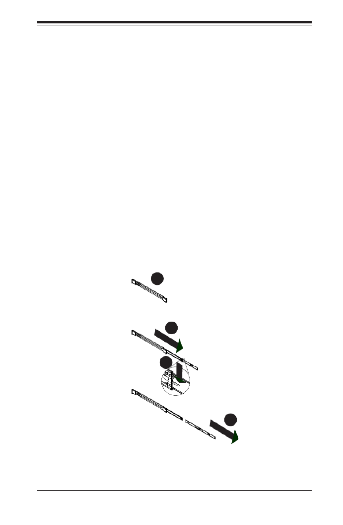
Figure 6-2: Extending and Releasing the Inner Rail
1
2
1
1
1
3
1
4
Locking Tabs
Each inner rail has a locking tab. This tab locks the chassis into place when installed
and pushed fully into the rack. These tabs also lock the chassis in place when fully
extended from the rack. This prevents the server from coming completely out of
the rack when when the chassis is pulled out for servicing.
Releasing the Inner Rail
Releasing Inner Rail from the Outer Rails
Identify the left and right outer rail assemblies as described on page 5-4.1.
Pull the inner rail out of the outer rail until it is fully extended as illustrated 2.
below.
Press the locking tab down to release the inner rail.3.
Pull the inner rail all the way out.4.
Repeat steps 1-3 for the second outer rail.5.

SC847 Chassis Manual
6-6
Figure 6-4: Inner Rails Installed on the Chassis
Figure 5-3: Installing the Inner Rails
Installing The Inner Rails on the Chassis
Installing the Inner Rails
Conrm that the left and right inner rails have been correctly identied.1.
Place the inner rail rmly against the side of the chassis, aligning the hooks 2.
on the side of the chassis with the holes in the inner rail.
Slide the inner rail forward toward the front of the chassis until the rail clicks 3.
into the locked position, which secures the inner rail to the chassis.
Secure the inner rail to the chassis with the screws provided. 4.
Repeat steps 1 through 4 above for the other inner rail.5.
3
1
4
1
4
2
Inner Rails

6-7
Chapter 5: Rack Installation
Installing the Outer Rails on the Rack
Installing the Outer Rails
Press upward on the locking tab at the rear end of the middle rail. 1.
Push the middle rail back into the outer rail.2.
Hang the hooks of the front of the outer rail onto the slots on the front of 3.
the rack. If necessary, use screws to secure the outer rails to the rack, as
illustrated above.
Pull out the rear of the outer rail, adjusting the length until it ts within the 4.
posts of the rack.
Hang the hooks of the rear portion of the outer rail onto the slots on the rear 5.
of the rack. If necessary, use screws to secure the rear of the outer rail to the
rear of the rack.
Repeat steps 1-5 for the remaining outer rail.6.
Figure 6-5: Extending and Releasing the Outer Rails
1
1
1
2
1
3
1
4

SC847 Chassis Manual
6-8
Figure 6-6: Installing into a Rack
Standard Chassis Installation
Installing the Chassis into a Rack
Conrm that the inner rails are properly installed on the chassis. 1.
Conrm that the outer rails are correctly installed on the rack. 2.
Pull the middle rail out from the front of the outer rail and make sure that the 3.
ball-bearing shuttle is at the front locking position of the middle rail.
Align the chassis inner rails with the front of the middle rails.4.
Slide the inner rails on the chassis into the middle rails, keeping the pressure 5.
even on both sides, until the locking tab of the inner rail clicks into the front of
the middle rail, locking the chassis into the fully extended position.
Depress the locking tabs of both sides at the same time and push the chassis 6.
all the way into the rear of the rack.
If necessary for security purposes, use screws to secure the chassis handles 7.
to the front of the rack.
Ball-Bearing
Shuttle

6-9
Chapter 5: Rack Installation
Optional Quick Installation Method
The following quick installation method may be used to install the chassis onto a
rack.
Installing the Chassis into a Rack
Install the whole rail assembly onto the rack as described on page 5-7. 1.
Release the inner rail without retracting the middle rail.2.
Install the inner rails on the chassis as previously described on page 5-6.3.
Install the chassis onto the middle rail as described in the previous section.4.

SC847 Chassis Manual
6-10
Adapters for Round and Threaded Hole Racks
The SC847 chassis includes adapter brackets for those customers using round hole
racks or racks with threaded holes size M5 or larger.
Installing the Adapter Bracket
Place the hooks of the front of the outer rail into the square holes of one of 1.
the adapter brackets.
Place the hooks of the rear of the outer rail into the square holes of a second 2.
adapter bracket.
Adjust the length of the outer rail to t within the rack uprights.3.
Secure the front adapter bracket to the front of the rack using the screws 4.
recommended by the rack manufacturer.
Secure the rear adapter bracket to the rear of the rack in the same manner. 5.

A-1
Appendix A: Chassis Cables
Appendix A
SC847 Cables and Hardware
A-1 Overview
This appendix lists supported cables for your chassis system. It only includes the
most commonly used components and congurations. For more compatible cables,
refer to the manufacturer of the motherboard you are using and our Web site at:
www.supermicro.com.
A-2 Cables Included with SC847 Chassis (SAS/SATA)
SC847
Part # Type Length Description
CBL-0088L Cable 9" Seven each, 10.5", 4-pin middle fan
power extension (PWM)
CBL-0087 Ribbon,
Round 20" 16-pin to 16-pin ribbon cable for
control panel
CBL-0160L- Cable 6' Two each, regional power cords
CBL-0217L Cable 22cm 16-pin control panel converter cable

SC847 Chassis Manual
A-2
A-3 Compatible Cables
These cables are compatible with the SC847 Chassis.
Description: This cable has one SFF-8484 (32-pin) connector on one end and
four SAS connectors (7 pins each) at the other. This cable connects from the host
(motherboard or other controller) to the backplane SAS hard drive port.
Cable Name: Quantity: SAS Cable 1
Part #: CBL-0175L
Alt. Name: "Big Four"
Alternate SAS/SATA Cables
Some compatible motherboards have different connectors. If your motherboard
has only one SAS connector that the SAS/SATA cables must share, use one of the
following cables. These cables must be purchased separately.
Description: This cable has one iPass (SFF-8087/Mini-SAS) connector (36-pin) at
one end and four SAS connectors on one end. This cable connects from the host
(motherboard or other controller) to the backplane SAS hard drive port.
Cable Name: Quantity: SAS Cable 1
Part #: CBL-0116
Alt. Name: iPass or "Small Four"

A-3
Appendix A: Chassis Cables
Extending Power Cables
Although Supermicro chassis are designed with to be efcient and cost-effective,
some compatible motherboards have power connectors located in different areas.
To use these motherboards you may have to extend the power cables to the mother
boards. To do this, use the following chart as a guide.
Power Cable Extenders
Number of Pins Cable Part # Length
24-pin CBL-0042 7.9” (20cm)
20-pin CBL-0059 7.9” (20cm)
8-pin CBL-0062 7.9” (20cm)
4-pin CBL-0060 7.9” (20cm)
Front Panel to the Motherboard
The SC847 chassis includes a cable to connect the chassis front panel to the
motherboard. If your motherboard uses a different connector, use the following list
to nd a compatible cable.
Front Panel to Motherboard Cable (Ribbon Cable)
Number of Pins
(Front Panel)
Number of Pins
(Motherboard Cable Part #
16-pin 16-pin CBL-0049
16-pin 20-pin CBL-0048
20-pin 20-pin CBL-0047
16-pin various* CBL-0068
20-pin various* CBL-0067
* Split cables: Use these cable if your motherboard requires several different con-
nections from the front panel.
Termékspecifikációk
| Márka: | Supermicro |
| Kategória: | Számítógép behuzás |
| Modell: | CSE-847E16-RJBOD1 |
Szüksége van segítségre?
Ha segítségre van szüksége Supermicro CSE-847E16-RJBOD1, tegyen fel kérdést alább, és más felhasználók válaszolnak Önnek
Útmutatók Számítógép behuzás Supermicro

29 December 2024
29 December 2024
29 December 2024
29 December 2024
29 December 2024
29 December 2024
29 December 2024
29 December 2024
29 December 2024
29 December 2024
Útmutatók Számítógép behuzás
- Számítógép behuzás Sharkoon
- Számítógép behuzás DeepCool
- Számítógép behuzás StarTech.com
- Számítógép behuzás Dell
- Számítógép behuzás Gigabyte
- Számítógép behuzás Phanteks
- Számítógép behuzás Asus
- Számítógép behuzás Genesis
- Számítógép behuzás Joy-It
- Számítógép behuzás MSI
- Számítógép behuzás Antec
- Számítógép behuzás Akasa
- Számítógép behuzás ModeCom
- Számítógép behuzás ADATA
- Számítógép behuzás Cooler Master
- Számítógép behuzás NZXT
- Számítógép behuzás Razer
- Számítógép behuzás Be Quiet!
- Számítógép behuzás 3M
- Számítógép behuzás Corsair
- Számítógép behuzás IStarUSA
- Számítógép behuzás Thermaltake
- Számítógép behuzás Cougar
- Számítógép behuzás HYTE
- Számítógép behuzás Zotac
- Számítógép behuzás Savio
- Számítógép behuzás Enermax
- Számítógép behuzás Logic
- Számítógép behuzás Lian Li
- Számítógép behuzás Icy Box
- Számítógép behuzás SilverStone
- Számítógép behuzás Techly
- Számítógép behuzás Intel
- Számítógép behuzás XPG
- Számítógép behuzás Monoprice
- Számítógép behuzás Zalman
- Számítógép behuzás Advantech
- Számítógép behuzás Evnbetter
- Számítógép behuzás Xigmatek
- Számítógép behuzás Akyga
- Számítógép behuzás Rosewill
- Számítógép behuzás AeroCool
- Számítógép behuzás Krux
- Számítógép behuzás 3R System
- Számítógép behuzás SilentiumPC
- Számítógép behuzás Fractal Design
- Számítógép behuzás Chenbro Micom
- Számítógép behuzás AZZA
- Számítógép behuzás Middle Atlantic
- Számítógép behuzás FSP
- Számítógép behuzás CoolerMaster
- Számítógép behuzás Montech
- Számítógép behuzás Jonsbo
- Számítógép behuzás Kolink
- Számítógép behuzás Leba
- Számítógép behuzás Hoffman
Legújabb útmutatók Számítógép behuzás
9 Április 2025
7 Április 2025
5 Április 2025

3 Április 2025
2 Április 2025
1 Április 2025
1 Április 2025
30 Március 2025
30 Március 2025

29 Március 2025