Használati útmutató NEC MultiSync LCD2490WUXI
Olvassa el alább 📖 a magyar nyelvű használati útmutatót NEC MultiSync LCD2490WUXI (136 oldal) a Monitor kategóriában. Ezt az útmutatót 7 ember találta hasznosnak és 2 felhasználó értékelte átlagosan 4.5 csillagra
Oldal 1/136


Index
Warning ..................................................................................................................................................1
Contents ................................................................................................................................................2
Quick Start ...........................................................................................................................................3
Controls .................................................................................................................................................9
Advanced OSM Controls ................................................................................................................... 16
Using the Auto Brightness Function ............................................................................................. 27
Using the CableComp™ Function ...................................................................................................29
Recommended use ............................................................................................................................30
Specifications ................................................................................................................................... 33
Features ..............................................................................................................................................35
Troubleshooting ................................................................................................................................ 37
References ..........................................................................................................................................38
Limited Warranty ..............................................................................................................................39
TCO’03 ................................................................................................................................................. 40
Manufacturer’s Recycling and Energy Information .................................................................. 41
Avertissement ...................................................................................................................................43
Contenu .............................................................................................................................................. 44
Mise en train ......................................................................................................................................45
Commandes ........................................................................................................................................ 51
Commandes OSM-Option avancée .................................................................................................58
Utilisation de la fonction de luminosité automatique ..............................................................69
Utilisation de la fonction de CableCompMD ...................................................................................71
Utilisation recommandée ................................................................................................................ 72
Fiche technique .................................................................................................................................75
Fonctions ............................................................................................................................................ 77
Dépannage ..........................................................................................................................................79
Références ......................................................................................................................................... 80
Garantie limitée ................................................................................................................................81
TCO’03 ..................................................................................................................................................82
Informations du fabricant relatives au recylage et aux économies d’énergie ..................83
Advertencia ........................................................................................................................................85
Contenidos ..........................................................................................................................................86
Inicio rápido .......................................................................................................................................87
Controles .............................................................................................................................................93
Controles OSM avanzados ..............................................................................................................100
Uso de la función Brillo automático ............................................................................................. 111
Uso de la función CableComp™ .....................................................................................................113
Uso recomendado ............................................................................................................................ 114
Specifications ................................................................................................................................. 117
Características .................................................................................................................................119
Solución de problemas ....................................................................................................................121
Referencias ....................................................................................................................................... 122
Garantía limitada ............................................................................................................................ 123
TCO’03 ................................................................................................................................................124
Información del fabricante sobre reciclado y energía ...........................................................125

1
CAUTION: TO REDUCE THE RISK OF ELECTRIC SHOCK, MAKE SURE POWER CORD IS UNPLUGGED FROM
WALL SOCKET. TO FULLY DISENGAGE THE POWER TO THE UNIT, PLEASE DISCONNECT THE POWER
CORD FROM THE AC OUTLET. DO NOT REMOVE COVER (OR BACK). NO USER SERVICEABLE PARTS
INSIDE. REFER SERVICING TO QUALIFIED SERVICE PERSONNEL.
This
symbol warns user that uninsulated voltage within the unit may have sufficient magnitude to
cause electric shock. Therefore, it is dangerous to make any kind of contact with any part inside this
unit.
This symbol alerts the user that important literature concerning the operation and maintenance of this
unit has been included. Therefore, it should be read carefully in order to avoid any problems.
WARNING
CAUTION
Canadian Department of Communications Compliance Statement
DOC: This Class B digital apparatus meets all requirements of the Canadian
Interference-Causing Equipment Regulations.
C-UL: Bears the C-UL Mark and is in compliance with Canadian Safety Regulations
according to CAN/CSA C22.2 No. 60950-1.
FCC Information
1.
Use the attached specified cables with the
MultiSync LCD2690WUXiTM
(L266RZ)/
Mul-
tiSync
LCD2490WUXiTM
(L246T0) color monitor so as not to interfere with radio and
television reception.
(1)
Please use the supplied power cord or equivalent to ensure FCC compliance.
(2) Please use the supplied shielded video signal cable, 15-pin mini D-SUB to
DVI-A cable, DVI-D to DVI-D cable, or D-SUB to D-SUB cable.
Use of other cables and adapters may cause interference with radio and
television reception.
2.
This equipment has been tested and found to comply with the limits for a Class B digital
device, pursuant to part 15 of the FCC Rules. These limits are designed to provide
reasonable protection against harmful interference in a residential installation. This
equipment generates, uses, and can radiate radio frequency energy, and, if not in-
stalled and used in accordance with the instructions, may cause harmful interference
to radio communications. However, there is no guarantee that interference will not
occur in a particular installation. If this equipment does cause harmful interference to
radio or television reception, which can be determined by turning the equipment off
and on, the user is encouraged to try to correct the interference by one or more of the
following measures:
• Reorient or relocate the receiving antenna.
• Increase the separation between the equipment and receiver.
• Connect the equipment into an outlet on a circuit different from that to which the receiver
is connected.
• Consult your dealer or an experienced radio/TV technician for help.
If necessary, the user should contact the dealer or an experienced radio/television techni-
cian for additional suggestions. The user may find the following booklet, prepared by
the Federal Communications Commission, helpful: ”How to Identify and Resolve Radio-
TV Interference Problems.“ This booklet is available from the U.S. Government Printing
Office, Washington, D.C., 20402, Stock No. 004-000-00345-4.
TO PREVENT FIRE OR SHOCK HAZARDS, DO NOT EXPOSE THIS UNIT TO RAIN OR MOISTURE. ALSO, DO NOT
USE THIS UNIT’S POLARIZED PLUG WITH AN EXTENSION CORD RECEPTACLE OR OTHER OUTLETS UNLESS THE
PRONGS CAN BE FULLY INSERTED.
REFRAIN FROM OPENING THE CABINET AS THERE ARE HIGH VOLTAGE COMPONENTS INSIDE. REFER SERVIC-
ING TO QUALIFIED SERVICE PERSONNEL.

2
Contents
Your new NEC MultiSync® LCD monitor box* should
contain the following:
• MultiSync LCD2690WUXi™ or LCD2490WUXi™ LCD monitor
with tilt/swivel/pivot/adjustable stand
• Power Cord
• Video Signal Cable (15-pin mini D-SUB male to DVI-A)
• Video Signal Cable (DVI-D to DVI-D cable)
• Video Signal Cable (mini D-SUB 15 pin to mini D-SUB 15 pin)
• User’s Manual
• Cable cover
• Screws (4) (for mounting the monitor to a flexible arm - see page 8)
* Remember to save your original box and packing material to transport or ship the monitor.
Power Cord
15-pin mini D-SUB
male to DVI-A
User’s Manual
Cable Cover
DVI-D to DVI-D cable
Screws (4)
Mini D-SUB cable

3
Quick Start
To attach the MultiSync® LCD monitor to your system,
follow these instructions:
1. Turn off the power to your computer.
2. For use with the PC or MAC with DVI digital output: Connect the DVI
signal cable to the connector of the display card in your system
(Figure A.1). Tighten all screws.
For a PC with Analog output: Connect the 15-pin mini D-SUB to DVI-A
signal cable to the connector of the display card in your system (Figure A.2).
For the MAC: Connect the MultiSync Macintosh cable adapter to the
computer, then attach the 15-pin mini D-SUB signal cable to the MultiSync
Macintosh cable adapter (Figure B.1).
NOTE: Some Macintosh systems do not require a
Macintosh cable adapter.
NOTE: To obtain the MultiSync Macintosh cable adapter call
NEC Display Solutions of America, Inc. (800) 632-4662.
3. Place hands on each side of the monitor. Tilt the LCD panel backwards to a
30-degree angle and lift up to the highest position. Connect all cables to
appropriate connectors (Figure 4).
4. To keep the cables neatly organized, place them into the cable
management system that is built into the stand.
Place the D-Sub cable and the power cable into the
specific hooks as indicated (Figure 5).
Place the DVI cable and the 15-pin mini D-Sub to DVI-A cable into the
hooks as indicated (Figure 6).
When using the monitor in Portrait mode, place the DVI cable and the 15-
pin mini D-Sub to DVI-A cable into the hooks as indicated (Figure 7).
5. Cables should rest flat against the stand.
Figure A.1 Figure A.2 Figure B.1Macintosh Adapter
(not included)

4
Make sure to leave enough slack in the cables so that the Tilt and the
Raise and Lower functions of the monitor are not impeded.
6. Hold all of the cables firmly and place the cable cover onto the
stand (Figure 8).
7. Slide the Cable Cover back into its correct position (Figure 9).
Connect the power cord to power outlet.
NOTE: Please refer to the Recommended Use section of this manual for
proper selection of power cord.
8. The vacation switch on the left side of the monitor must be in the
ON position for the monitor to function (Figure 10).
Turn on the monitor using the front power button, then turn on the computer.
NOTE: The Vacation Switch is a true on/off switch. If this
switch is in the OFF position, the monitor cannot be
turned on using the front button.
DO NOT turn the vacation switch ON/OFF repeatedly.
9. For Analog input only: Upon initial setup, the No-Touch Auto Adjust feature
automatically adjusts the monitor to the optimal settings that are needed for
most signal timings.
For further adjustments, refer to the Controls section of this User’s Manual
for a full description of the OSM controls.
For download information on the Windows® INF file for your monitor, visit www.
necdisplay.com/support.
NOTE: If you have any problems, please refer to the Troubleshooting
section of this User’s Manual.
Highest
Stand
Position
Power cord
DC-OUT
DVI-D DVI-I
D-SUB
30 Tilt
Figure 4 Figure 5
Figure 6
Quick Start – continued
(DC out for optional NEC products such as
the Soundbar attachment. Do not use this
connector unless specified.)

5
Quick Start – continued
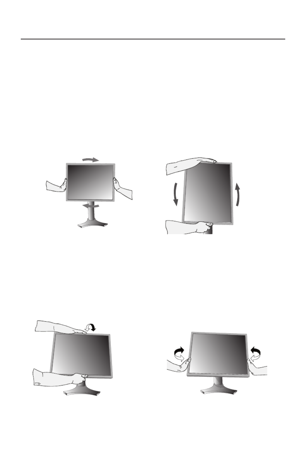
Raising and Lowering Monitor Screen
The monitor screen may be raised or lowered while in either Portrait or Land-
scape mode. To raise or lower the screen, place hands on each side of the
monitor and lift or lower to the desired height (Figure RL.1).
NOTE: Handle with care when raising or lowering the monitor screen.
Figure RL.1
Figure 7
Figure 8
Vacation
Switch
Power
Button
Figure 9 Figure 10
NOTE: The Vacation Switch is a true on/off switch. If
this switch is in the OFF position, the monitor
cannot be turned on using the front button.
6
Quick Start – continued
Screen Rotation
Before rotating, the screen must be raised to the highest level to avoid accidentally
damaging the screen and to avoid pinching fi ngers. To raise the screen, place
hands on each side of the monitor and lift up to the highest position (Figure RL.1).
To rotate screen, place hands on each side of the monitor screen and turn clock-
wise from Landscape to Portrait or counter-clockwise from Portrait to Landscape
(Figure R.1).
Note: To toggle the orientation of the OSM menu between Landscape and
Portrait modes, refer to the “Controls” section of this user’s manual.
Swivel
Grasp both sides of the monitor screen
with your hands and adjust the swivel
as desired (Figure TS.2).
Tilt
Grasp top and bottom sides of the moni-
tor screen with your hands and adjust the
tilt as desired (Figure TS.1).
NOTE: Handle with care when tilting and swiveling the monitor screen.
Figure R.1
Figure TS.1 Figure TS.2

7
Remove Stand for Mounting
The stand can be removed in order to mount the monitor using an alternate, VESA
approved, mounting method.
1. Disconnect all cables.
2. Place hands on each side and raise the monitor up to the highest position
(see Raising and Lowering Monitor Screen page 5).
3.
Place monitor face down on a nonabrasive surface (Figure S.1).
4. Place one hand around the base and one hand on the Quick Release Lever.
Move the Quick Release Lever in the direction indicated by the arrows
(Figure S.2) .
5. Lift up the bottom of the stand to unhook it from the monitor (Figure S.3).
The monitor can now be mounted using and alternate method.
Reverse the process to reattach stand.
NOTE: Handle with care when removing monitor stand.
(Figure S.2)
Quick Start – continued
(Figure S.1)
(Figure S.3)
1. Pull lever towards stand.
2. Slide lever to the right.
1
2

8
Flexible Arm Installation
This LCD monitor is designed for use with a fl exible arm.
To mount the monitor to a fl exible arm:
1. Remove the stand (see page 7). Remove Monitor Stand for Mounting
2. Use the 4 screws that are included to attach the arm to the monitor
(Figure F.1).
Quick Start – continued
CAUTION: Use ONLY the 4 screws that are included when mounting to avoid damaging
the monitor and the stand or arm. For safety requirements, the monitor must be
mounted to an arm which guaranties the necessary stability under consideration
of the weight of the monitor. The LCD monitor should only be used with an
approved arm (e.g. GS mark).
When using mounting accessories (e.g. VESA (200 X 100)) other than VESA
(100 X 100), use the screws M4 size (Length: bracket thickness + 10mm).
(Figure F.1)
100mm
100mm
200mm
9
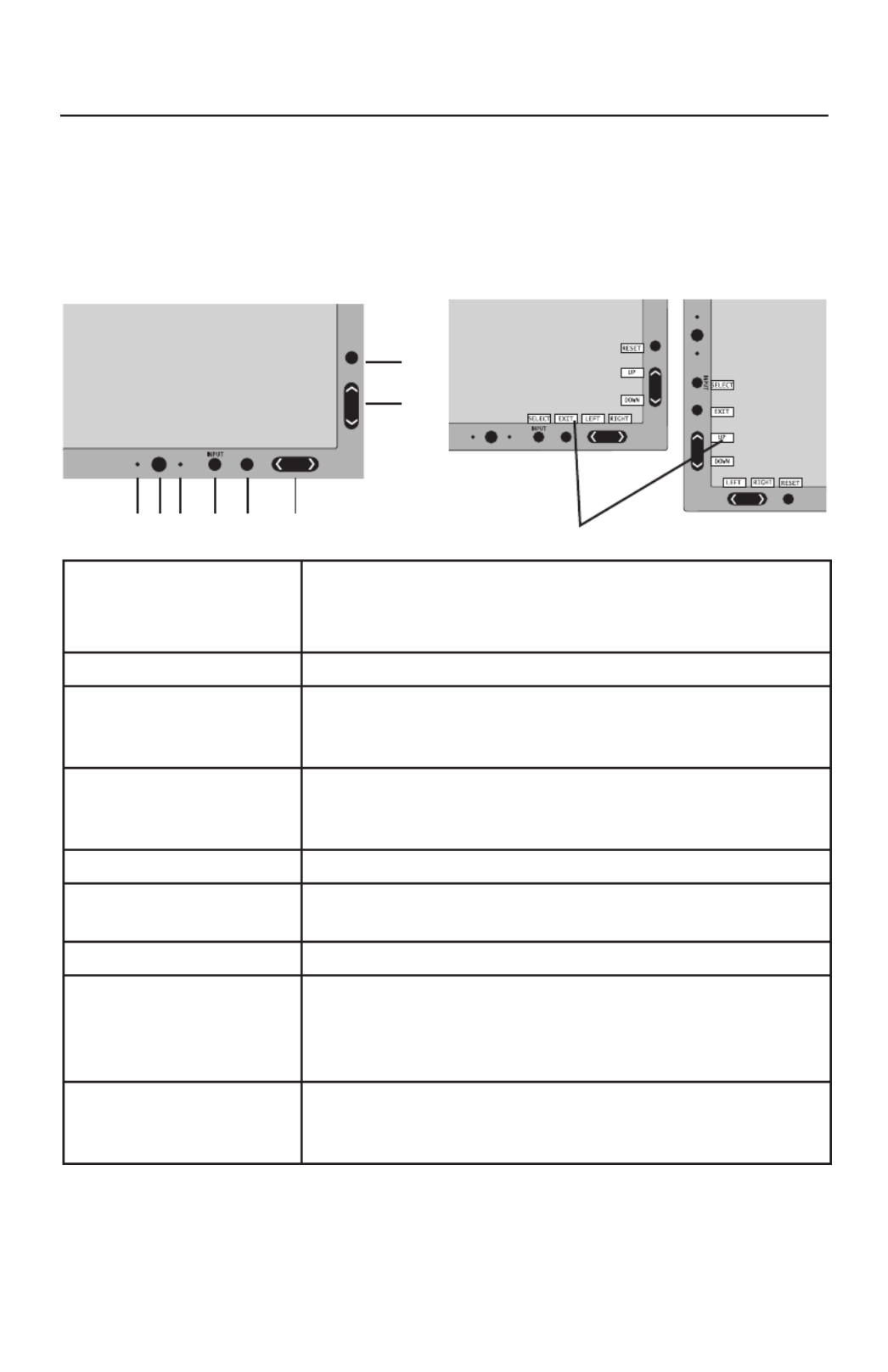
*The “LEFT/RIGHT” and “UP/DOWN” buttons functionality is interchangeable
depending on the orientation (landscape/portrait) of the OSM.
Controls
1 AMBIBRIGHT SENSOR Detects the level of ambient lighting allowing the monitor
to make adjustments to various settings resulting in a more
comfortable viewing experience. Do not cover this sensor.
2 POWER Turns the monitor on and off.
3 LED Indicates that the power is on.
Can be changed between blue and green in the Advanced
OSM Control menu.
4 INPUT/SELECT Enters the OSM Control menu. Enters OSM sub menus.
Changes the input source when not in the OSM Control
menu.
5 EXIT Exits the OSM sub menu. Exits OSM Control menu.
6 LEFT/RIGHT Navigates to the left or right through the OSM Control
menu.
7 UP/DOWN Navigates up or down through the OSM Control menu.
8 RESET/ROTATE OSM Resets the OSM back to factory settings.
Pressing when the OSM is not showing rotates the OSM
Control menu between portrait and landscape mode.*
See page 24 Tag9 OSM ROTATION.
9 KEY GUIDE The Key Guide appears on screen when the OSM control
menu is accessed. The Key Guide will rotate when the
OSM control menu is rotated.
OSM® (On-Screen Manager) control buttons, located on the front
of the monitor, function as follows:
To access OSM menu, press any of the following control buttons: EXIT, LEFT, RIGHT, UP, or
DOWN.
To change the input source signal when the OSM is closed, press the INPUT/SELECT button.
1 2 3 4 5 6
7
8
9Portrait
Landscape

10
Brightness/Contrast Controls
BRIGHTNESS: Adjusts the overall image and background screen brightness.
CONTRAST: Adjusts the image brightness in relation to the background.
AUTO CONTRAST (Analog input only): Adjusts the image displayed for
non-standard video inputs.
ECO MODE: Decreases the amount of power consumed by reducing the
brightness level.
1: Decreases the brightness by 25%.
2: Decreases the brightness by 50%.
CUSTOM: Decreases the brightness level as determined by
the user. Refer to the Advanced OSM menu for custom setting instructions.
AUTO BRIGHTNESS: There are three settings for Auto Brightness.
OFF: Auto Brightness does not function.
1: Adjusts the brightness automatically by detecting the brightness level of your
environment and adjusting the monitor accordingly with the best BRIGHTNESS
setting (see page 36 for AmbiBright™ explanation), making the viewing
experience more comfortable.
2: Adjusts the BRIGHTNESS level of the monitor to the best setting based on the
amount of white being displayed on the monitor. This function does not utilize
the AmbiBright sensor.
NOTE: Do not cover the AmbiBright sensor.
When “AUTO LUMINANCE”(See page 16) is ON, this function is disabled.
BLACK LEVEL: Adjusts the black level.
Auto Adjust (Analog input only)
AUTO ADJUST:
Automatically adjusts the Image Position, H. Size, and Fine settings.
Controls – continued

11
Image Controls
LEFT / RIGHT:
Controls Horizontal Image Position within the LCD’s display area.
DOWN / UP: Controls Vertical Image Position within the
LCD’s display area
.
H.SIZE (V.SIZE) (Analog input only): Increases or decreases the horizontal
(or vertical) size.
If the “Auto Adjust function” does not provide a satisfactory picture,
further tuning can be performed manually using the “H. Size (or V. Size)”
function (dot clock).
To manually adjust the monitor, a Moiré test pattern should be used.
This function may alter the width of the picture. Use Left/Right Menu to center
the image on the screen.
If the H. Size (or V. Size) is set incorrectly, the screen would show vertical
banding, like the drawing on the left. The image should be clear.
FINE
(Analog input only):
If the “Auto Adjust” and the “H.Size” functions do not
provide a
satisfactory picture, further
tuning can be performed using the
“Fine” function. Adjusting
this setting improves focus, clarity and image stability.
For Fine adjustment, a
Moiré test pattern should be used. If the Fine setting is
incorrect, the screen would show horizontal banding like the drawing on the left.
The image should be clear.
AUTO FINE (Analog input only): Automatically adjusts the FINE settings.
When the AUTO FINE control is ON adjustment occurs approximately every 33
minutes.
EXPANSION: Selects the zoom mode.
FULL: The image is expanded to 1920 x 1200, regardless of the resolution.
ASPECT: The image is expanded without changing the aspect ratio.
OFF: The image is not expanded.
CUSTOM: Refer to the ADVANCED OSM Controls section of this user’s
manual for detailed instructions.
Controls – continued
Incorrect
Adjustment
Incorrect
Adjustment
Correct
Adjustment
Correct
Adjustment

12
AccuColor® Control Systems
ACCUCOLOR® CONTROL SYSTEM: Seven preset color settings.
For preset settings: 1, 2, 3 and 5, the following levels can be adjusted:
TEMPERATURE: Adjust the white temperature by increasing or decreasing this setting.
A lower color temperature will make the screen reddish and a higher color tempera-
ture will make the screen bluish.
WHITE (White Balance): If TEMPERATURE needs further adjustment, the individual R/
G/ B/ levels of the white point can be adjusted. To adjust the R/G/B levels, CUS-
TOM must be showing as the TEMPERATURE selection.
HUE: Adjusts the hue of each color*1 . The change in color will appear on screen and
the menu color bars will show the amount of adjustment.
SATURATION: Adjusts the color depth of each color*1. Press the “RIGHT” button and
the color vividness increases.
OFFSET: Adjusts the color brightness of each color*1. Press “RIGHT” button and the
color Brightness increases.
*1: RED, YELLOW, GREEN, CYAN, BLUE, MAGENTA
The sRGB and NATIVE, color presets are standard and cannot be changed.
The PROGRAMMABLE setting can only be adjusted using color calibration software
such as NEC’s GammaComp or Spectraview II.
Tools
SHARPNESS:
This function is digitally capable of keeping a crisp image within any
resolution at any time. This setting can be set independently for different signal
timings (resolution settings).
DVI SELECTION: This function selects the DVI input mode. If the DVI selection changes,
you must restart the computer.
AUTO: When using the DVI-D to DVI-D cable, the DVI SELECTION is DIGITAL.
When using the D-SUB to DVI-A cable, the DVI SELECTION is ANALOG.
DIGITAL: DVI digital input is available.
ANALOG: DVI analog input is available.
NOTE: When using a MAC with digital output: before turning on the MAC, the
DVI Input mode on the monitor must be set to DIGITAL in the DVI SELEC
TION menu. To set the DVI SELECTION to “DIGITAL” press the SELECT
button then CONTROL button when the DVI signal cable is connected to
the DVI-I connector of the monitor. Otherwise the MAC may not turn on.
NOTE:
Depending on the type of PC/Video card or the type of video signal
cable used, the DVI SELECTION function may not operate.
Controls – continued

13
HDCP CONTENT (Digital Input Only): Selects the type of input to be used with
HDCP CONTENT.
OFF: When a PC or other computer equipment is connected, select “OFF”.
ON: When a DVD player or other type of high definition device is connected, select “ON”.
NOTE: Interlaced signals (480i, 576i, 1080i) are not supported. If you have any
problems, please refer to the Troubleshooting section of this User’s Manual.
VIDEO DETECT: Selects the method of video detection when more than one video
input source is connected to the monitor.
FIRST: If “FIRST” is selected as the VIDEO DETECT option, the
monitor displays the signal from the first input port. If there is no signal present
at the first input port, then the monitor will search for a signal from the next
input port.
If a new input signal is connected to another of the monitor’s input ports while
the monitor is in FIRST mode, the monitor DOES NOT automatically
SWITCH to the new source.
LAST: If “LAST” is selected as the VIDEO DETECT option, then
each time a new input source is detected, the monitor will automatically display
the new signal.
NONE: The monitor will only search other input ports while the power is on.
OFF TIMER:
Monitor will automatically power down after a user-determined length
of time passes. Before powering off, a message will appear on the screen asking
the user if they want to delay the turn off time by 60 minutes. Press any OSM
button to delay the turn off time.
IPM: The Intelligent Power Manager allows the monitor to enter into a power saving
mode after a period of inactivity. The IPM has three settings.
OFF: Monitor does not go into power save mode when the input signal is lost.
STANDARD: Monitor enters power save mode automatically when the input
signal is lost.
OPTION: Monitor enters power save mode automatically when the amount of
surrounding light goes below the level that is determined by the user. The level
can be determined in Tag 7 of the Advanced OSM Control menu.
When in power save mode, the LED on the front of the monitor blinks amber.
While in power save mode, push any of the front buttons, except for POWER and
SELECT to return to normal operation.
When the amount of surrounding light returns to normal levels, the monitor will
automatically return to normal mode.
COLORCOMP:
This function electronically compensates for the slight variations in
the white uniformity level, as well as for deviations in color that may occur throughout
the display area of the screen. These variations are characteristic of LCD panel
technology. This function improves the color and evens out the luminance uniformity
of the display.
NOTE: Using the COLORCOMP feature reduces the overall peak luminance of
the display. If greater luminance is desired over the uniform performance of
the display, then COLORCOMP should be turned off.
Controls – continued

14
MENU Tools
LANGUAGE: OSM control menus are available in eight languages.
OSM LEFT/RIGHT: You can choose the location where the OSM appears on your screen.
The LEFT/RIGHT submenu moves the OSM horizontally.
OSM DOWN/UP: You can choose the location where the OSM appears on your
screen. This DOWN/UP submenu moves the OSM vertically.
OSM TURN OFF: The OSM control menu will stay on as long as it is use.
You can select how long the monitor waits after the last touch of a button to shut off the
OSM control menu. Time can be set between10-120 seconds, in 5 second increments.
OSM LOCK OUT: This control completely locks out access to some of or to all of the
OSM control functions. When attempting to activate OSM controls while in the Lock
Out mode, a screen will appear indicating the OSM controls are locked out.
There are four ways to use OSM LOCK OUT function:
1. OSM LOCK OUT with BRIGHTNESS and CONTRAST control: This mode
locks all OSM functions except for BRIGHTNESS and CONTRAST.
To activate, press the SELECT and “Up” buttons simultaneously, while in the
OSM menu.
To deactivate, press the SELECT and “Up” buttons simultaneously, while in
the OSM menu.
2. OSM LOCK OUT with no control: This mode prevents access to all
OSM functions.
To activate, press the SELECT and “Right” buttons simultaneously.
To deactivate, press the SELECT and “Right” buttons simultaneously,
while in the OSM menu.
3. OSM LOCK OUT with BRIGHTNESS (only) control: This mode locks all OSM
functions except for BRIGHTNESS.
To activate, press the SELECT, “Left” and "Down" buttons simultaneously,
while in the OSM menu.
To deactivate, press SELECT, then “Left” and "Down" buttons simultaneously
while in the OSM menu.
4. CUSTOM: refer to the Advanced OSM Menu.
OSM TRANSPARENCY: Adjusts the transparency of the OSM Menu.
OSM COLOR: “Tag window frame color”, “Item select color” and “Adjust window
frame color” can be changed to Red, Green, Blue, or Gray.
Controls – continued

15
Controls – continued
RESOLUTION NOTIFIER: The Resolution Notifier warns the user if the input signal
to the monitor is set at something other than the optimized resolution of
1920 x 1200. If the monitor detects a signal that is not at the optimized
resolution then, after 30 seconds, a warning message will appear on the screen.
When the Resolution Notifier is ON, the warning will appear every 30 seconds.
The Resolution Notifier can be turned OFF in the OSM.
HOT KEY: When this function is activated, the brightness and contrast of the
monitor can be adjusted without entering the OSM menu.
The “Left” or “Right” buttons adjust the brightness level.
The “Down” or “Up” buttons adjust the contrast level.
FACTORY PRESET: Selecting the factory preset allows the user to reset most of the
OSM control settings back to the factory settings.
Individual settings can be reset by highlighting the control that needs to be reset,
and pressing the RESET button.
Information
Provides information about the current resolution being displayed by the monitor.
Also provides technical information including which preset timing is being used as
well as the horizontal and vertical frequencies.
OSM WARNINGS: OSM Warning menus alert the user when there are
problems with the input signal. These warnings will disappear when the Exit
button is pressed.
NO SIGNAL: This warning appears when there is no Horizontal or
Vertical Sync. After power is turned on or when there is a change of input
signal, the No Signal window will appear.
RESOLUTION NOTIFIER: This warning appears when the monitor detects
a resolution other than the optimized resolution. For example, if the
optimized resolution for the monitor is 1920 x 1200 and a signal using a
resolution of 1280 x 1024 is detected, the “Resolution Notifier” warning
will appear.
OUT OF RANGE: This warns if the input signal is out of the optimized
resolution and refresh rate range that is used by monitor.
PORTRAIT WARNING: When the monitor is used in the portrait position, the
brightness value will be reduced to 300 cd/m2. If the Portrait Warning is ON,
a message will appear on the screen for 10 seconds.
LUMINANCE WARNING: When the backlight cannot display the desired
luminance, a message will appear on the display. To avoid this, reduce the BRIGHT-
NESS level or set the AUTO LUMINANCE function to OFF (page 16, TAG1).
Note: It is possible to change the DVI SELECTION, to change the IPM or to
change the HDCP CONTENT settings while the “NO SIGNAL” or “OUT
OF RANGE” messages are displayed.
For advanced user menu items see “Advanced OSM Controls”.

16
Advanced OSM Controls
In addition to the standard On Screen Menu (OSM), the Advanced OSM Control menu
allows the user to have much more control over regular OSM functions as well as ac-
cess to functions not available in the standard OSM.
To use the advanced menu
• Turn off your monitor using the front "POWER" button.
• Turn on your monitor by pushing the “POWER” and “INPUT/SELECT” button
simultaneously for at least one second. Then press one of the following front OSM
buttons: EXIT, LEFT, RIGHT, UP, or DOWN.
• You will see the Advanced OSM Control menu. This menu is larger than the standard
OSM and has numbered tags instead of icons.
• To exit the Advanced OSM, turn off and restart your monitor in the normal way.
To adjust the setting, use the buttons on the front panel to highlight the desired tag and
press "SELECT". Use the buttons to make the adjustment. Once the setting is at the
desired level press "SELECT" and then "EXIT" to go back to the previous menu.
Tag 1 Brightness
Adjusts the overall image and screen background brightness.
Press “Left” or “Right” to adjust.
When AUTO LUMINANCE is OFF or 2, the brightness level is adjusted/measured using
percentage (%).
When AUTO LUMINANCE is 1 or 3, brightness level is adjusted/measured using
cd/m2. This is the “Estimated Brightness” level.
Contrast
Adjusts the image brightness and contrast in relation to the background.
Auto Contrast
(Analog input only)
Adjusts the image displayed for non-standard video inputs.
Auto Black Level
(Analog input only)
Adjusts the black level for non-standard video inputs.
ECO Mode
Decreases the amount of power consumed by reducing the
brightness level.
1: Decreases the brightness by 25%.
2: Decreases the brightness by 50%.
CUSTOM: Decreases the brightness level as determined by the user.
ECO Mode Custom
Allows the user to set a preferred brightness level when ECO Mode is in use.
Auto Brightness
AUTO BRIGHTNESS has three settings.
OFF: Auto Brightness does not function.
1: Adjusts the brightness automatically by detecting the brightness level of your environment
and adjusting the monitor accordingly with the best BRIGHTNESS setting (see page 36 for
AmbiBright™ explanation), making the viewing experience more comfortable.
2: Adjusts the BRIGHTNESS level of the monitor to the best setting based on the amount of
white being displayed on the monitor. This function does not utilize the Ambibright sensor.
NOTE: Do not cover AmbiBright sensor. When “AUTO LUMINANCE” is ON, this function
is disabled.
Black Level
Adjusts the black level.
AUTO
LUMINANCE
Stabilizes the luminosity and color of the image. While the BRIGHTNESS level is adjusting, the
numerical value blinks.
OFF: No function
1: Stabilize Luminance
2: Stabilize Color
3: Stabilize Luminance and color
Note: The AUTO LUMINANCE function is only available when “AUTO BRIGHTNESS” is OFF.
When “AUTO LUMINANCE” is 1 or 3, maximum value of the Brightness level is limited.
When “AUTO LUMINANCE” is OFF or 2, the brightness level is adjusted/ measured
using percentage(%).
When “AUTO LUMINANCE” is 1 or 3, brightness level is adjusted/measured using cd/m2
.
This is the “Estimated Brightness” level.
17
Tag 1
LOW BRIGHT
MODE
The BRIGHTNESS setting can lower the brightness level.
LOW BRIGHT MODE can be used to lower the brightness even
further, if desired.
ON: Brightness is reduced by an additional 50%.
ADVANCED: Brightness is reduced by an additional 25%.
NOTE: When PROGRAMABLE is set for the Gamma Selection (tag5),
LOW BRIGHT MODE is disabled.
Tag 2 R-H. POSITION
(Analog input only) Adjusts the position of the RED component of the image.
Press “Left” or “Right” to adjust.
G-H. POSITION
(Analog input only) Adjusts the position of the GREEN component of the image. Press
“Left” or “Right” to adjust.
B-H. POSITION
(Analog input only) Adjusts the position of the BLUE component of the image.
Press “Left” or “Right” to adjust.
R-FINE
(Analog input only) Adjusts the “FINE” setting of the RED component of the image. Press
”Left” or “Right” to adjust.
G-FINE
(Analog input only) Adjusts the “FINE” setting of the GREEN component of the image.
Press ”Left” or “Right” to adjust.
B-FINE
(Analog input only) Adjusts the “FINE” setting of the BLUE component of the image. Press
”Left” or “Right” to adjust.
R-SHARPNESS
(Analog input only) Adjusts the “SHARPNESS” setting of the RED component of the im-
age. Press ”Left” or “Right” to adjust.
G-SHARPNESS
(Analog input only) Adjusts the “SHARPNESS” setting of the GREEN component of the
image. Press ”Left” or “Right” to adjust.
B-SHARPNESS
(Analog input only) Adjusts the “SHARPNESS” setting of the BLUE component of the im-
age. Press ”Left” or “Right” to adjust.
DVI LONG CABLE
(Digital input only) Compensates for image degradation caused by using a long DVI
cable. There are 4 possible settings, with “0” being the lowest level
of compensation and “3” being the highest level.
The default setting is “1”.
Tag 3 AUTO ADJUST
(Analog input only) Automatically adjusts the Image Position, H. Size, and
Fine settings.
SIGNAL AD-
JUST
(Analog input only)
Determines what settings are adjusted when Auto Adjust is per-
formed. The choices are “SIMPLE” and “FULL”.
Press ”Left” or “Right” to select.
H-size, Fine, H/V Position Contrast
SIMPLE O X
FULL O O
O: Automatic Adjustment X: No Automatic Adjustment
NOTE: Automatic Adjustment does not work at
resolutions less than 800 x 600 resolution.
Advanced OSM Controls – continued
18
Tag 3 AUTO ADJUST
LEVEL
(Analog input only)
Determines which items are to be adjusted when the AUTO
ADJUST function is activated.
The choices are “SIMPLE” “FULL”, and “DETAIL”.
Press ”Left” or “Right” to select.
Size, Fine,
Position
Contrast Black Level, Long
Cable capability**
Time
SIMPLE O X X 1 Sec.
FULL O O X 1.5 Sec.
DETAIL* O O O 5 Sec.
O: Automatic Adjustment X: No Automatic Adjustment
*
“DETAIL” activates automatic long cable (skew, peaking) adjustment.
** Black level, RGB sharpness, RGB delay and RGB position can be adjusted using the
* Long Cable Software. To download the software, please visit www.necdisplay.com.
A-NTAA SW
(Analog input only)
The Advanced No Touch Auto Adjust function is able to
recognize new signals even when neither the resolution nor the
refresh rate has changed. If several PCs are connected to the
monitor, and each transmit very similar (or even the same) sig-
nals in terms of resolution and refresh rates, the monitor recog-
nizes that there is a new signal and automatically optimizes the
picture without the need for any action on the part of the user.
OFF: A-NTAA is disabled.
ON: If a change in signal is detected A-NTAA will adjust the
monitor to the optimal settings for the new signal. If no change
in the signal is detected then A-NTAA does not activate. The
screen will be blank while the monitor optimizes the signal.
OPTION: Functions the same as ON, except that the screen
does not go blank when the monitor makes adjustments for
changes in signal, allowing the monitor to display the new sig-
nal faster. When using an external switching device to connect
2 or more PCs to the monitor,using either the ON or OPTION
setting is suitable.
Advanced OSM Controls – continued
19
Tag 4 H. POSITION Sets Horizontal Image Position within the display area of the
LCD. Press “Left” or “Right” to adjust.
V. POSITION Sets Vertical Image Position within the display area of the LCD.
Press “Left” or “Right” to adjust.
H. SIZE
(Analog input only)
Increases or decreases the horizontal (or vertical) size.
If the “Auto Adjust function” does not give a satisfactory picture,
further tuning can be performed manually using the “H. Size (or
V. Size)” function (dot clock).
To manually adjust the monitor, a Moiré test pattern should be
used.
This function may alter the width of the picture. Use Left/Right
Menu to center the image on the screen. (see page 11).
FINE
(Analog input only)
If the “Auto Adjust” and the “H.Size” functions do not give a
satisfactory picture, further tuning can be performed using the
“Fine” function. Increasing or decreasing this setting improves
focus, clarity and image stability.
(see page 11)
AUTO FINE
(Analog input only)
This function automatically and periodically adjusts the “FINE”
setting for when there is a change in the input signal.
Adjustment occurs approximately every 33 minutes.
H. RESOLUTION Adjusts the Horizontal resolution.
Press “Left” or “Right” to adjust.
V. RESOLUTION Adjusts the Vertical resolution.
Press “Left” or “Right” to adjust.
EXPANSION Selects the zoom mode.
FULL: The image expands to 1920 x 1200, regardless of the
resolution.
ASPECT: The image expands without changing the aspect ratio.
OFF: The image is not expanded.
CUSTOM: When CUSTOM is selected as the Expansion mode,
it becomes possible to adjust the H. ZOOM., V. ZOOM, and
ZOOM POS.
H.ZOOM
Available in Custom
Expansion mode only
The image is expanded from 1 to 3 times in the horizontal
(H. EXPANSION) direction by 0.01 increments.
V.ZOOM
Available in Custom
Expansion mode only
The image is expanded from 1 to 3 times in the vertical
(V. EXPANSION) direction by 0.01 increments.
ZOOM POS.
Available in Custom
Expansion mode only
Sets the point from which the screen will be expanded when ei-
ther H.ZOOM or V.ZOOM is selected as the expansion method.
Options are CENTER and LEFT TOP.
CENTER: H.ZOOM expands the image from the center out-
ward to the sides of the screen. V.ZOOM expands the image
from the center towards the top and bottom of the screen.
LEFTTOP: LEFTTOP indicates the set point for image expansion
(LEFT in H.ZOOM, TOP in V. ZOOM). If the resolution does not
fill out the screen, when expanding, the image will not expand
past the TOP or the LEFT of the screen. The image can be
expanded past the right and bottom edges of the screen.
Advanced OSM Controls – continued

20
Tag 5 GAMMA
SELECTION
Allows you to manually select the grayscale tone curve.
There are five possible selections:
NO CORRECTION: No Correction possible.
2.2: The exponential gamma curve value is fixed at 2.2.
OPTION: There are two optional selections.
1: This setting is recommended for Video input sources.
Dark areas will look brighter and high bright areas will
look darker.
2: Curve based on the DICOM GSDF, for use with grayscale
images.
PROGRAMMABLE: A programmable gamma curve can be
loaded using NEC software such as GammaComp, Gamma-
CompMD and SpectraView II.
CUSTOM: The following settings can be adjusted when
CUSTOM is selected as the GAMMA SELECTION setting.
Custom Value: Selectable Gamma ranging from 0.5 to 4.0
in 0.1 increments. Not adjustable in sRGB color preset.
OFFSET: Digitally adjusts the black level after the signal is
converted from analog to digital.
Tag 6 COLOR CONTROL
ACCUCOLOR® CONTROL SYSTEM: Seven preset color settings.
For preset settings: 1, 2, 3 and 5, the following levels can be
adjusted:
TEMPERATURE: Adjust the white temperature by increasing or
decreasing this setting. A lower color temperature will make the
screen reddish and a higher color temperature will make the
screen bluish.
WHITE (White Balance): If TEMPERATURE needs further adjust-
ment, the individual R/G/B levels of the white point can be
adjusted. To adjust the R/G/B levels, CUSTOM must be show-
ing as the TEMPERATURE selection.
HUE: Adjusts the hue of each color*1. The change in color will
appear on screen and the menu color bars will show the amount
of adjustment.
SATURATION: Adjusts the color depth of each color*1. Press the
“RIGHT” button and the color vividness increases.
OFFSET: Adjusts the color brightness of each color*1.
Press “RIGHT” button and the color Brightness increases.
*1: RED, YELLOW, GREEN, CYAN, BLUE, MAGENTA
The sRGB and NATIVE color presets are standard and cannot
be changed.
The PROGRAMMABLE setting can only be adjusted using color
calibration software
such as NEC’s GammaComp or
Spectraview II.
Advanced OSM Controls – continued

21
Tag 7 SHARPNESS This function is digitally capable of keeping an image crisp at any
resolution at any time. This setting can be set independently for
different signal timings (resolution settings).
DVI SELECTION This function selects the DVI input mode. If the DVI selection
changes, you must restart your computer.
AUTO: When using the DVI-D to DVI-D cable, the DVI SELECTION
is DIGITAL.
When using the D-SUB to DVI-A cable, the DVI SELECTION
is ANALOG.
DIGITAL: DVI digital input is available.
ANALOG: DVI analog input is available.
HDCP CONTENT
(Digital Input Only) Selects the type of input to be used with HDCP CONTENT.
OFF: When a PC or other computer is connected, select “OFF”.
ON: When a DVD player or other type of high definition device is
connnected, select “ON”.
Note: Interlaced signals (480i, 576i, 1080i) are not supported. If
you have any problems, please refer to the Troubleshooting section
of this User’s Manual.
VIDEO DETECT Selects the method of video detection when more than one video
input is connected.
FIRST: If “FIRST” is selected as the VIDEO DETECT option, the moni-
tor displays the signal from the first input port. If there is no signal
present at the first input port, then the monitor will search for a
signal from the next input port.
If a new input signal is connected to another of the monitor’s input
ports while the monitor is in FIRST mode, the monitor will not switch
automatically to the new source.
LAST: If “LAST” is selected as the VIDEO DETECT option, then each
time a new input source is detected, the monitor automatically
displays the new signal.
NONE: The monitor will only search other input ports while the
power is on.
OFF TIMER Monitor will automatically power off after a user-determined length
of time passes. Before powering off, a message will appear on the
screen asking the user if they want to delay the turn off time by 60
minutes. Press any OSM button to delay the turn off time.
IPM
(Intelligent Power
Manager)
The Intelligent Power Manager allows the monitor to enter into a
power saving mode after a period of inactivity. The IPM has three
settings.
OFF: Monitor does not go into power save mode when the input
signal is lost.
STANDARD: Monitor enters power save mode automatically when
the input signal is lost.
OPTION: Monitor enters power save mode automatically when the
amount of surrounding light goes below the level that is determined
by the user.
IPM SETTING Adjusts the luminance value for IPM.
OVER DRIVE Turns the OVER DRIVE function ON or OFF. Over Drive may reduce
blurring that occurs in some moving images. When Over Drive is
on, response time is improved.
Advanced OSM Controls – continued
22
Tag 7
continued SIDE BORDER
COLOR
Adjusts the side black bars color between black and white.
For wide aspect monitors.
LED BRIGHTNESS
Controls the brightness of the LED on the front of the
monitor.
LED COLOR
The LED on the front can be blue or green.
COLORCOMP This function electronically compensates for the slight variations
in the white uniformity level as well as for slight differences in
color that may occur throughout the display area of the screen.
These variations are characteristics of LCD panel technology.
This function improves the color and evens out the luminance
uniformity of the display.
NOTE: Using the COLORCOMP feature does reduce the overall
peak luminance of the display. If greater luminance is desired
over the uniform performance of the display, then COLOR-
COMP should be turned off.
COLORCOMP
LEVEL
Select the level for ColorComp adjustments.
Tag 8 LANGUAGE OSM control menus are available in eight languages. Press
“Left” or “Right” to select.
OSM H.POSITION You can choose where you would like the OSM control image
to appear on your screen. Selecting OSM Position allows you
to manually adjust the location of the OSM control menu left, or
right.
OSM V.POSITION You can choose where you would like the OSM control image
to appear on your screen. Selecting OSM Position allows you
to manually adjust the location of the OSM control menu up, or
down.
OSM TURN OFF The OSM control menu will stay on as long as it is in use.
You can select how long the monitor waits after the last touch of
a button to shut off the OSM control menu. The preset choices
are 10-120 seconds by 5 seconds increments. Press “Left” or
“Right” to select.
OSM LOCK OUT This control completely locks out access to all OSM control
functions. When attempting to activate OSM controls while in
the Lock Out mode, a screen will appear indicating the OSM
controls are locked out.
There are four ways to use OSM LOCK OUT function:
1: OSM LOCK OUT with BRIGHTNESS and CONTRAST
control: This mode locks all OSM functions except for
BRIGHTNESS and CONTRAST.
To activate, press the SELECT and “Up” buttons
simultaneously, while in the OSM menu.
To deactivate, press the SELECT and “Up” buttons
simultaneously, while in the OSM menu.
Advanced OSM Controls – continued

23
Tag 8
continued
OSM LOCKOUT
continued
2: OSM LOCK OUT with no control: This mode prevents access
to all OSM functions. To activate, press the SELECT and
“Right” buttons simultaneously. To deactivate, press the SELECT
and “Right” buttons simultaneously, while in the OSM menu.
3: OSM LOCK OUT with BRIGHTNESS (only) control: This
mode locks all OSM functions except for BRIGHTNESS.
To activate, press the SELECT, “Left” and “Down” buttons
simultaneously, while in the OSM menu.
To deactivate, press SELECT, “Left” and “Down” buttons
simultaneously, while in the OSM menu.
4: CUSTOM: Press RESET and EXIT to enter the CUSTOM
Menu. Select ENABLE or DISABLE for: POWER KEY, INPUT
SEL, HOT KEY (BRIGHTNESS/CONTRAST) ECO MODE,
WARNING (RESOLUTION NOTIFIER/OSM LOCK OUT).
To Deactivate the OSM Lock Out function, press RESET and
EXIT to bring up the LOCK OUT warning. Press SELECT,
SELECT, <, >, <, >, EXIT.
OSM
TRANSPARENCY
Adjusts the transparency of the OSM MENU.
OSM COLOR “Tag window frame color”, “Item select color”& ”Adjust Win-
dow frame color” can be changed.
SIGNAL
INFORMATION
Signal information can be displayed in the corner of the screen.
Signal information is either “ON/OFF”.
RESOLUTION
NOTIFIER
The Resolution Notifier warns the user if the input to the monitor
is set to something other than the optimized resolution of
1920 x 1200. If the monitor detects a signal that is not at the
optimized resolution, after 30 seconds a warning message will
appear on the screen.
HOT KEY When this function is activated, the brightness and contrast of
the monitor can be adjusted by using the front buttons without
entering the OSM menu.
The “Left” or “Right” buttons adjust the brightness level.
The “Down” or “Up” buttons adjust the contrast level.
FACTORY PRESET Selecting the factory preset allows the user to reset most of the
OSM control settings back to the factory settings.
Individual settings can be reset by highlighting the control need-
ing to be reset, and pressing the RESET button.
Tag 9 GRAYSCALE
MODE
This mode changes the display’s screen image from color to
grayscale.
There are 3 settings for monochrome mode.
OFF: The display’s screen image is normal.
MODE1: The monitor uses only the Green component of the
RGB color input signal to display grayscale.
MODE2: The monitor converts the RGB color input signal to
YUV to display the image as grayscale.
Advanced OSM Controls – continued

24
Tag 9
continued
OSM ROTATION
AUTO: The OSM rotates automatically when the monitor is rotated. OSM ROTA-
TION is set to AUTO by default.
MANUAL: To rotate the OSM, press the ROTATE OSM button when the OSM
is not showing.
IMAGE ROTATION
AUTO: The display image automatically rotates according to the orientation of
the OSM. If “AUTO” is selected in the “OSM ROTATION” menu, the display
image rotates according to the orientation of the monitor.
OFF: The display image is not rotated. IMAGE ROTATION is set to OFF by
default.
ON: The display image always rotated.
PORTRAIT
WARNING
When the monitor is used in the portrait position, the brightness value will be
reduced to 300 cd/m2. If the Portrait Warning is ON, a message will appear
on the screen for10 seconds.
DDC/CI
DDC/CI ENABLE/DISABLE: Turns on or off the two way communication and
control of the monitor.
SCREEN SAVER
Use the SCREEN SAVER to reduce the risk of image persistence.
MOTION (Default OFF): Screen image moves periodically in 4 directions in
order to reduce the risk of image retention.
Timing for MOTION can be set so the screen image moves in intervals from
every 10 to 900 seconds. Timing is set in 10-second increments.
OPTION (Default REDUCED): There are two optional selections.
REDUCED: Screen image is reduced to 95% size and is moved periodically in
4 directions.
Screen may appear slightly less sharp than normal. The full image appears on
the display.
FULL: Screen image is set to FULL and is moved periodically in 4 directions.
Screen image goes outside of the display area in the direction that it shifts so
that a portion of the image may appear to be cut off.
GAMMA (Default OFF): When OFF, the GAMMA selection that the display uses
is the same as the GAMMA selection in Tag5 (page 20).
When ON is selected, the GAMMA curve (except PROGRAMMABLE) becomes
narrow, reducing the contrast and cutting down the risk of image retention.
NOTE: SCREEN SAVER does not function when the TILE MATRIX function is
enabled.
INPUT SETTING
VIDEO BAND WIDTH (Analog input only): Adjusts the bandwidth of the video
signal. Can be used to eliminate undesired video noise from a poor signal.
Press “Left” or “Right” to select.
SYNC THRESHOLD (Analog input only): Adjusts the slice level of a synchroniza -
tion signal. Press “SELECT” to move the adjustment menu. Adjusts the sensitivity
of the separate or composite input signals. Try this option if the FINE adjustment
does not successfully eliminate the noise.
SOG THRESHOLD (Analog input only): Adjusts the sensitivity of the Sync On
Green input signals. Adjusts the slice level when separating a synchronization
from Sync On Green signal input. Press “Left” or “Right” to select.
EDGE LOCK: Operating your monitor at a non-standard timing may cause im-
ages to appear darker than normal or to have color distortion. Use of the Edge
Lock control will adjust images to their normal state.
Tag A
TILE MATRIX
The “TILE MATRIX” feature allows one image to be displayed over multiple
screens.This feature can be used with up to 25 monitors. (5 horizontal x 5
vertical) Using the Tile Matrix function requires the PC output signal to be sent
through a distribution amplifier to each of the individual monitors.
ENABLE: Select “ON”, to expand the signal to the selected TILE MATRIX settings.
H MONITOR: Selects the number of horizontal displays.
V MONITOR: Selects the number of vertical displays.
MONITOR NO.: Selects a position to expand the screen.
Advanced OSM Controls – continued

25
Tag A
continued
TILE MATRIX
continued
TILECOMP: Works in tandem with “TILE MATRIX” to com-
pensate for the bezel width of the tiled monitors in order to
accurately display the image.
TileComp using 4 monitors (black area shows monitor frames).
The EXPANSION mode will be set to “FULL” when the “TILE
MATRIX” is activated.
Tag B DATE & TIME Sets the current date and time for the internal clock.
Date and Time has to be set in order for the “SCHEDULE”
feature to work properly.
DAYLIGHT SAVING: For those timezones where Daylight
Saving Time (Summertime) is observed.
Tag C SCHEDULE Programs the monitor’s working schedule. Sets the hour and
day of the week when the monitor powers on or off. Also sets
the input port. Select “EXIT” to set schedule.
Using the “SCHEDULE” function allows you to set up to seven
different scheduled time intervals when the LCD Monitor will
be activated. You can select the time the monitor turns on and
turns off, the day of week the monitor is activated, and which
input source the monitor will use for each scheduled activation
period. A check mark in the box next to the number of the
schedule indicates that the selected schedule is in effect. To
select which schedule to set, use the up/down arrows to move
the cursor vertically to select a schedule (1 to 7) to be set. Use
the “down” or “up” buttons to move the red bar horizontally
within the particular schedule. The “SELECT” button is used to
make a selection . If you create a schedule but do not want to
use a power on time, select “--” in the “ON” time slot. If you do
not want to use a power off time select “--” in the OFF time slot.
If there is no input selected (“-----” showing in the input spot) the
input from the previous schedule will be used. Selecting
EVERY DAY within a schedule takes priority over other sched-
ules that are set up to operate weekly.
Schedules are numbered 1-7. If two schedules are programmed
for the same time, then the highest numbered schedule has pri-
ority. For example schedule #7 will take priority over schedule
#5. When schedules are overlapping, a scheduled Power ON
time has priority over a scheduled Power OFF time.
When the “OFF TIMER” (see page 21) is set, the “SCHEDULE”
function is disabled.
Advanced OSM Controls – continued
monitor1 monitor2
monitor3 monitor4
monitor1 monitor2
monitor3 monitor4
TileComp OFF TileComp ON

26
Advanced OSM Controls – continued
Tag C
continued SCHEDULE
continued Before powering off, a message will appear on the screen ask-
ing the user if they want to delay the turn off time by 60 minutes.
Press any OSM button to delay the turn off time.
Tag D ECO MODE
INFORMATION
Displays the estimated power saving information in watt-hours.
Tag E INFORMATION Provides information about the current display resolution as well
as technical data, including the preset timing currently being
used. Horizontal and vertical frequencies is also displayed.

27
SETUP
Use the following procedure to determine the Brightness Range that the monitor will use
when the Auto Brightness function is activated.
1. Set the BRIGHT level. This is the brightness
level that the monitor will go up to when the
ambient light level is highest. Make sure the
room is at its brightest when setting this level.
Select “1” in the AUTO BRIGHTNESS menu
(Figure 1).
Then use the front buttons to move the cursor
up to the BRIGHTNESS setting. Choose the
desired brightness level (Figure 2).
2. Set the DARK level. This is the level of
brightness that the monitor will go down to
when the ambient light level is low. Make
sure the room is at its darkest when setting
this level.
Then use the front buttons to move the cursor
up to the BRIGHTNESS setting. Choose the
desired brightness level (Figure 3).
Figure 1
Figure 2
Figure 3
Using the Auto Brightness function
The brightness of the LCD screen can be set to increase or decrease depending on the
amount of ambient light within the room. If the room is bright, the monitor becomes
correspondingly bright. If the room is dim, then the monitor will dim accordingly. The
purpose of this function is to make the viewing experience more comfortable to the eye
in a variety of lighting conditions.
NOTE: The Auto Brightness function is set to OFF by default.
When “AUTO LUMINANCE” is ON, this function is disabled.

28
lighting level of room
Bright Ambient
Lighting Conditions
Dim Ambient
Lighting Conditions
Screen Brightness value using the Auto Brightness function
BRIGHTNESS level set
for the monitor to use
when ambient lighting
level is low.
BRIGHTNESS level set
for the monitor to use
when ambient lighting
level is high.
BRIGHTNESS range
Lb : Border between bright and dim lighting conditions; set at factory
L1 : BRIGHTNESS level set for the monitor to use when ambient lighting level is high (L1>Lb)
L2 : BRIGHTNESS level set for the monitor to use when ambient lighting level is low (L2<Lb)
L1 and L2 are the brightness levels set by the user to compensate for changes in ambient
lighting.
Figure 4
When the “Auto Brightness” function is enabled, the Brightness level of the screen changes
automatically according to the lighting conditions of the room (Figure 4).
Using the Auto Brightness function - cont.
30
Safety Precautions and Maintenance
FOR OPTIMUM PERFORMANCE, PLEASE NOTE THE
FOLLOWING WHEN SETTING UP AND USING
THE MULTISYNC® LCD COLOR MONITOR:
Recommended Use
• DO NOT OPEN THE MONITOR. There are no user serviceable parts inside and opening or remov-
ing covers may expose you to dangerous shock hazards or other risks. Refer all servicing to qualified
service personnel.
• Do not spill any liquids into the cabinet or use your monitor near water.
• Do not insert objects of any kind into the cabinet slots, as they may touch dangerous voltage points,
which can be harmful or fatal or may cause electric shock, fire or equipment failure.
• Do not place any heavy objects on the power cord. Damage to the cord may cause shock or fire.
• Do not place this product on a sloping or unstable cart, stand or table, as the monitor may fall, causing
serious damage to the monitor.
• When operating the MultiSync LCD monitor with its AC 125-240V power supply, use a power supply
cord that matches the power supply voltage of the AC power outlet being used. The power supply
cord you use must have been approved by and comply with the safety standards of your country. (Type
H05VV-F should be used in Europe)
• In UK, use a BS-approved power cord with molded plug having a black (5A) fuse installed for use with
this monitor. If a power cord is not supplied with this monitor, please contact your supplier.
• Do not place any objects onto the monitor and do not use the monitor outdoors.
• The lamps in this product contain mercury. Please dispose according to state, local
or federal law.
• Do not bend power cord.
• Do not use monitor in very hot, humid, dusty, or oily areas.
• Do not cover vents on monitor.
• Vibration can damage the backlight. Do not install where the monitor will be exposed to continual
vibration.
• If monitor or glass is broken, handle with care. Do not come in contact with the liquid crystal.
Immediately unplug your monitor from the wall outlet and refer servicing to
qualified service personnel under the following conditions:
• When the power supply cord or plug is damaged.
• If liquid has been spilled, or objects have fallen into the monitor.
• If the monitor has been exposed to rain or water.
• If the monitor has been dropped or the cabinet damaged.
• If the monitor does not operate normally by following operating instructions.
• Allow adequate ventilation around the monitor so that heat can properly dissipate.
• Do not block ventilated openings or place the monitor near a radiator or other heat sources.
• Do not put anything on top of monitor.
• The power cable connector is the primary means of detaching the system from the
power
supply. The monitor should be installed close to a power outlet which is easily accessible.
• Handle with care when transporting. Save packaging for transporting.
Image Persistence
Image persistence is when a residual or “ghost” image of a previous image remains visible on the
screen. Unlike CRT monitors, LCD monitors’ image persistence is not permanent, but constant images
being displayed for a long period of time should be avoided.
To alleviate image persistence, turn off the monitor for as long as the previous image was displayed.
For example, if an image was on the monitor for one hour and a residual image remains, the monitor
should be turned off for one hour to erase the image.
NOTE: As with all personal display devices, NEC DISPLAY SOLUTIONS recommends using a moving
screen saver at regular intervals whenever the screen is idle or turning off the monitor when not in
use.
CAUTION

31
• For optimum performance, allow 20 minutes for
warm-up.
• Adjust the monitor height so that the top of the
screen is at or slightly below eye level. Your
eyes should look slightly downward when view-
ing the middle of the screen.
•
Position your monitor no closer than 16 inches
and no further away than 28 inches from your
eyes. The optimal distance is 20 inches.
• Rest your eyes periodically by focusing on an
object at least 20 feet away. Blink often.
• Position the monitor at a 90° angle to windows and other light sources to
minimize glare and reflections. Adjust the monitor tilt so that ceiling lights
do not reflect on your screen.
• If reflected light makes it hard for you to see your screen, use an antiglare filter.
• Clean the LCD monitor surface with a lint-free, non-abrasive cloth. Avoid using
any cleaning solution or glass cleaner!
• Adjust the monitor’s brightness and contrast controls to enhance readability.
• Use a document holder placed close to the screen.
• Position whatever you are looking at most of the time (the screen or refer-
ence material) directly in front of you to minimize turning your head while
you are typing.
• Avoid displaying fixed patterns on the monitor for long periods of time to avoid
image persistence (after-image effects).
• Get regular eye checkups.
CORRECT PLACEMENT AND ADJUSTMENT OF THE MONITOR
CAN REDUCE EYE, SHOULDER AND NECK FATIGUE. CHECK THE
FOLLOWING WHEN YOU POSITION THE MONITOR:
Recommended Use – continued

32
Ergonomics
To realize the maximum ergonomics benefits, we recommend the following:
• Adjust the Brightness until the background raster disappears.
• Do not position the Contrast control to its maximum setting.
• Use the preset Size and Position controls with standard signals.
• Use the preset Color Setting.
• Use non-interlaced signals with a vertical refresh rate more than 60Hz.
• Do not use primary color blue on a dark background, as it is difficult to see
and may produce eye fatigue to insufficient contrast.
For more detailed information on setting up a healthy work environment, write
the American National Standard for Human Factors Engineering of Visual Dis-
play Terminal Workstations – ANSI-HFS Standard No. 100-1988 – The Human
Factors Society, Inc. P.O. Box 1369, Santa Monica, California 90406.
Cleaning the LCD Panel
• When the liquid crystal panel becomes dusty or dirty, wipe gently with a
soft cloth.
• Do not rub the LCD panel with hard or coarse material.
• Do not apply pressure to the LCD surface.
• Do not use OA cleaner as it will cause deterioration or discolor the LCD
surface.
Cleaning the Cabinet
• Unplug the power supply.
• Gently wipe the cabinet with a soft cloth.
• Dampen a cloth with a neutral detergent and water, wipe the cabinet and
then dry with a soft cloth.
NOTE: Many plastics are used on the surface of the cabinet. DO NOT clean
with benzene, thinner, alkaline detergent, alcoholic system detergent,
glass cleaner, wax, polish cleaner, soap powder, or insecticide. Do
not place rubber or vinyl against the cabinet for long periods. These
types of fluids and fabrics can cause the paint to deteriorate, crack,
or peel.
Recommended Use – continued

33
Specifications
LCD Module Diagonal: 25.5 inch Active matrix; thin film transistor (TFT)
Viewable Image Size: 25.5 inch liquid crystal display (LCD); 0.287 mm dot
Native Resolution (Pixel Count): 1920x1200 pitch; 400cd/m 2 white luminance; XtraView+™
technology;800:1contrast ratio, typical
Input Signal Video: ANALOG 0.7 Vp-p/75 Ohms Digital Input: DVI(with HDCP)
Sync: Separate sync. TTL Level Positive/Negative
Composite sync. Positive/Negative
Sync on Green (Video 0.7Vp-p and Sync Negative 0.3V p-p)
Display Colors 16,777,216 Dependant on display card used.
Synchronization Horizontal: 31.5 kHz to 93.8 kHz; 119.2 kHz*2
(Analog)
Automatically
Range 31.5 kHz to 91.1 kHz; 119.2 kHz*2
(Digital)
Automatically
Vertical: 50.0 Hz to 85.0 Hz Automatically
Viewing Angle Left/Right: ± 89˚ (CR>10)
Up/Down: ± 89˚ (CR>10)
Image Formation Time 16ms (Typ.) 8ms (Gray to Gray Typ)
Resolutions Supported 640 x 480*1 at 60 Hz to 85 Hz
Some systems may not support all modes listed 720 x 350*1 at 70 Hz to 85 Hz
720 x 400*1 at 70 Hz to 85 Hz
800 x 600*1 at 56 Hz to 85 Hz
832 x 624*1 at 75 Hz
1024 x 768*1 at 60 Hz to 85 Hz
1152 x 864*1 at 70 Hz to 85 Hz
1152 x 870 *1 at 75 Hz
1152 x 900 *1 at 66 Hz
1280 x 960*1 at 60 Hz to 85 Hz
1280 x 1024 *1 at 60 Hz to 85 Hz
1400 x 1050*1 at 60 Hz to 75 Hz
1440 x 900*1 at 60 Hz to 85 Hz
1600 x 1200 *1 at 60 Hz to 75 Hz(Analog) 1600 x 1200*1 at 60 Hz (Digital)
1680 x 1050 *1 at 60 Hz to 75 Hz(Analog) 1680 x 1050*1 at 60 Hz (Digital)
1920x 1200*1 at 60 Hz...............................
NEC DISPLAY SOLUTIONS cites
recommended
1024x 1280 at 60 Hz resolution for optimal
display performance.
1200 x 1920 *1 at 60 Hz(Analog)
480P (720 x 480*1 at 60 Hz)
576P (720 x 576*1 at 50 Hz)
720P (1280 x 720*1 at 50 Hz, 60Hz)
1080P (1920 x 1080*1 at 50 Hz, 60Hz)
Active Display Area Landscape : Horiz. : 550 mm/21.7 inches
Vert. : 344 mm/13.5 inches
Portrait : Horiz. : 344 mm/13.5 inches
Vert. : 550 mm/21.7 inches
Power Supply 100 - 240 V ~ 50/60 Hz
Current Rating 1.5 – 0.75A (with option) for reference 1.2A (without option)
For Mexico 2.1A
Dimensions Landscape: 589.8 mm (W) x 444.2 - 594.2 mm (H) x 306.0 mm (D)
23.2 inches (W) x 17.5 - 23.4 inches (H) x 12.0 inches (D)
Portrait: 383.4 mm (W) x 601.3 - 697.4 mm (H) x 306.0 mm (D)
15.1 inches (W) x 23.7 - 27.5 inches (H) x 12.0 inches (D)
Height Adjustment: 150 mm / 5.9 inches
Weight 13.1 kg
28.8 lbs
Environmental Considerations
Operating Temperature: 5°C to 35°C/41°F to 95°F
Humidity: 30% to 80%
Altitude: 0 to 10,000 Feet
Storage Temperature: -10°C to 60°C/14°F to 140°F
Humidity: 10% to 85%
Altitude: 0 to 40,000 Feet
*1 Interpolated Resolutions: When resolutions are shown that are lower than the pixel count of the LCD module, text may appear different. This is
normal and necessary for all current flat panel technologies when displaying non-native resolutions full screen. In flat panel technologies, each dot
on the screen is actually one pixel, so to expand resolutions to full screen, an interpolation of the resolution must be done.
*2 1200 x 1920 resolution only.
NOTE: Technical specifications are subject to change without notice.
Monitor MultiSync®
Specifications LCD2690WUXi Notes

34
Specifications – continued
LCD Module Diagonal: 24.1 inch Active matrix; thin film transistor (TFT)
Viewable Image Size: 24.1 inch liquid crystal display (LCD); 0.270 mm dot
Native Resolution (Pixel Count): 1920x1200 pitch; 400cd/m 2 white luminance; XtraView+™
technology; 800:1 contrast ratio, typical
Input Signal Video: ANALOG 0.7 Vp-p/75 Ohms Digital Input: DVI(with HDCP)
Sync: Separate sync. TTL Level Positive/Negative
Composite sync. Positive/Negative
Sync on Green (Video 0.7Vp-p and Sync Negative 0.3V p-p)
Display Colors 16,777,216 Dependant on display card used.
Synchronization Horizontal: 31.5 kHz to 93.8 kHz; 119.2 kHz*2
(Analog)
Automatically
Range 31.5 kHz to 91.1 kHz; 119.2 kHz*2
(Digital)
Automatically
Vertical: 50.0 Hz to 85.0 Hz Automatically
Viewing Angle Left/Right: ± 89˚ (CR>10)
Up/Down: ± 89˚ (CR>10)
Image Formation Time 16ms (Typ.) 8ms (Gray to Gray Typ)
Resolutions Supported 640 x 480*1 at 60 Hz to 85 Hz
Some systems may not support all modes listed 720 x 350*1 at 70 Hz to 85 Hz
720 x 400*1 at 70 Hz to 85 Hz
800 x 600*1 at 56 Hz to 85 Hz
832 x 624*1 at 75 Hz
1024 x 768*1 at 60 Hz to 85 Hz
1152 x 864*1 at 70 Hz to 85 Hz
1152 x 870 *1 at 75 Hz
1152 x 900 *1 at 66 Hz
1280 x 960*1 at 60 Hz to 85 Hz
1280 x 1024 *1 at 60 Hz to 85 Hz
1400 x 1050*1 at 60 Hz to 75 Hz
1440 x 900*1 at 60 Hz to 85 Hz
1600 x 1200 *1 at 60 Hz to 75 Hz(Analog) 1600 x 1200*1 at 60 Hz (Digital)
1680 x 1050 *1 at 60 Hz to 75 Hz(Analog) 1680 x 1050*1 at 60 Hz (Digital)
1920x 1200*1 at 60 Hz...............................
NEC DISPLAY SOLUTIONS cites
recommended
1024x 1280 at 60 Hz resolution for optimal
display performance.
1200 x 1920 *1 at 60 Hz(Analog)
480P (720 x 480*1 at 60 Hz)
576P (720 x 576*1 at 50 Hz)
720P (1280 x 720*1 at 50 Hz, 60Hz)
1080P (1920 x 1080*1 at 50 Hz, 60Hz)
Active Display Area Landscape : Horiz. : 518 mm/20.4 inches
Vert. : 324 mm/12.8 inches
Portrait : Horiz. : 324 mm/12.8 inches
Vert. : 518 mm/20.4 inches
Power Supply 100 - 240 V ~ 50/60 Hz
Current Rating 1.1 – 0.55A (with option) for reference 0.92A(without option)
For Mexico 2.1A
Dimensions Landscape: 554.2 mm (W) x 432.4 - 582.4 mm (H) x 306.0 mm (D)
21.8 inches (W) x 17.0 - 22.9 inches (H) x 12.0 inches (D)
Portrait: 359.8 mm (W) x 565.7 - 679.6 mm (H) x 306.0 mm (D)
14.2 inches (W) x 22.3 - 26.8 inches (H) x 12.0 inches (D)
Height Adjustment: 150 mm / 5.9 inches
Weight 12.3 kg
27.1 lbs
Environmental Considerations
Operating Temperature: 5°C to 35°C/41°F to 95°F
Humidity: 30% to 80%
Altitude: 0 to 10,000 Feet
Storage Temperature: -10°C to 60°C/14°F to 140°F
Humidity: 10% to 85%
Altitude: 0 to 40,000 Feet
*1 Interpolated Resolutions: When resolutions are shown that are lower than the pixel count of the LCD module, text may appear different. This is
normal and necessary for all current flat panel technologies when displaying non-native resolutions full screen. In flat panel technologies, each dot
on the screen is actually one pixel, so to expand resolutions to full screen, an interpolation of the resolution must be done.
*2 1200 x 1920 resolution only.
NOTE: Technical specifications are subject to change without notice.
Monitor MultiSync®
Specifications LCD2490WUXi Notes

35
Features
Ambix3™ Technology: Triple input technology allowing up to 3 input sources to be
connected to a single monitor. The DVI-I connector supports both analog and digital
input signals. Legacy analog input is supported using a traditional 15-pin VGA connec-
tor. Ambix3 provides traditional MultiSync® technology compatibility for analog as well
as DVI-based digital compatibility for digital inputs. DVI-based digital interfaces include
DVI-D, DFP and P&D.
DVI-I: The integrated interface ratified by the Digital Display Working Group (DDWG)
that allows both digital and analog connectors off of one port. The “I” stands for integra-
tion for both digital and analog, The digital portion is DVI-based.
DVI-D: The digital-only subset of DVI ratified by the Digital Display Working Group
(DDWG) for digital connections between computers and displays. As a digital-only
connector, analog support is not provided off a DVI-D connector. As a DVI-based digital
only connection, only a simple adapter is necessary for compatibility between DVI-D and
other DVI-based digital connectors such as DFP and P&D.
DFP (Digital Flat Panel): An all-digital interface for flat panel monitors which is signal
compatible with DVI. As a DVI-based digital only connection, only a simple adapter is
necessary for compatibility between DFP and other DVI-based digital connectors such
as DVI and P&D.
P&D (Plug and Display): The VESA standard for digital flat panel monitor interfaces.
It is more robust than DFP since it allows for other options off a signal connector (options
like USB, analog video and IEEE-1394-995). The VESA committee has recognized that
DFP is a subset of P&D. As a DVI-based connector (for the digital input pins), only a
simple adapter is necessary for compatibility between P&D and other DVI-based digital
connector such as DVI and DFP.
Pivoting Stand: Allows users to adjust the monitor to the orientation that best fits their
application, either Landscape orientation for wide documents, or Portrait orientation for
the ability to preview a full page on one screen at one time. The Portrait orientation is
also perfect for full screen video conferencing.
Reduced Footprint: Provides the ideal solution for environments requiring superior
image quality but with size and weight limitations. The monitor’s small footprint and low
weight allow it to be moved or transported easily from one location to another.
AccuColor® Control System:
Allows the user to adjust the colors on the screen and
customize the color accuracy of the monitor to a variety of color standards.
OSM® (On-Screen Manager) Controls: Allow you to quickly and easily adjust all
elements of your screen image via simple to use on-screen menus.
ErgoDesign® Features: Enhanced human ergonomics to improve the working environ-
ment, protect the health of the user and save money. Examples include
OSM controls for
quick and easy image adjustments, tilt base for preferred angle of vision, small footprint
and compliance with MPRII and TCO guidelines for lower emissions
.
Plug and Play: The Microsoft® solution with the Windows® operating system facilitates
setup and installation by allowing
the monitor to send its capabilities (such as screen size
and resolutions supported)
directly to your computer, automatically optimizing display
performance.

36
IPM® (Intelligent Power Manager) System: Provides innovative power-saving methods that
allow the monitor to lower the power consumption level when on but not in use, saving two-thirds
of your monitor energy costs, reducing emissions and lowering the air conditioning costs of the
workplace.
Multiple Frequency Technology: Automatically adjusts monitor to the display card’s scanning
frequency, thus displaying the resolution required.
FullScan® Capability: Allows you to use the entire screen area in most resolutions, significantly
expanding image size.
XtraView+™ Wide Viewing Angle Technology: Allows the display image to be seen at
wide viewing angles. Close to 180 degrees off center axis, for both up-down and left-right viewing
angles. XtraView+ is active in either portrait or landscape orientations. Please see the Specifications
page for exact viewing angle of each monitor.
VESA Standard Mounting Interface: Allows users to connect their MultiSync monitor to any
VESA standard third party mounting arm or bracket. Allows for the monitor to be mounted on a wall
or an arm using any third party compliant device.
Ultra-thin-frame design: Allows you to view more of your ideas and less of the monitor bezel,
while freeing up more horizontal and vertical desktop space for multiple-monitor applications.
NaViSet™ software: Offers an expanded and intuitive graphical interface, allowing you to
more easily adjust OSM display settings via mouse and keyboard.
CableComp™: Automatic long cable compensation prevents image quality degradation caused
by long cable lengths.
Advanced No Touch Auto Adjust: When a new input source is detected. The monitor then
optimizes picture settings without the need for extra adjustment on the part of the user.
Rapid Response™: Delivers virtually uninterrupted, undistorted viewing of full-motion video ap-
plications.
sRGB Color Control: A new optimized color management standard which allows for color
matching on computer displays and other peripherals. The sRGB, which is based on the calibrated
color space, allows for optimal color representation and backward compatibility with other com-
mon color standards.
ColorComp: This feature compensates for slight variations in the white uniformity level that may
occur on the screen and improves the color and evens out the luminance uniformity of the display.
Over Drive: Improves gray to gray response time.
Adjustable stand with pivot capability: Adds flexibility to your viewing preferences.
Quick Release stand: Allows fast removal of the stand.
AmbiBright™ technology: Automatically adjusts the backlight level depending on the level of
ambient lighting.
91% of the NTSC RGB Color Gamut: Means more vibrant and accurate colors.
12-bit gamma/12-bit LUT: Allows precise control over the display’s Tone Response Curve
without reducing the number of displayable colors.
Auto Image Rotation: allows the screen image to switch between portrait and landscape mode
automatically, depending on the orientation of the monitor. No additional software is required.
Features – continued

37
Troubleshooting
No picture
• The signal cable should be completely connected to the display card/computer.
• The display card should be completely seated in its slot.
• Check the Vacation Switch should be in the ON position.
• Front Power Switch and computer power switch should be in the ON position.
• Check to make sure that a supported mode has been selected on the display card or system being used. (Consult
display card or system manual to change graphics mode.)
• Check the monitor and your display card with respect to compatibility and recommended settings.
• Check the signal cable connector for bent or pushed-in pins.
• Check the signal input, “DVI-D”, “DVI-I”, or “D-Sub”.
• Ensure the DVI input mode is set to DIGITAL when the MAC digital output is connected to the
DVI-I connector.
• If the front LED is blinking amber, check the status of the IPM mode (see page 13).
• When using a DVD player or any other type of high-definition device, please do not use interlaced signals. If
the monitor detects an interlaced signal, an OSM warning will appear. If this OSM warning appears, please do
the following: press the RESET and EXIT buttons simultaneously, to temporarily show the image coming from the
high-definition device. While the image is visible, change the signal of the device from interlaced to progressive
(non-interlaced). Consult the User's Manual included with the device for detailed information on changing the
signal from interlaced to progressive.
Power Button does not respond
• Unplug the power cord of the monitor from the AC outlet to turn off and reset the monitor.
• Check the Vacation Switch on the left side of the monitor.
Image Persistence
• Image persistence is when a residual or “ghost” image of a previous image remains visible on the screen. Unlike
CRT monitors, LCD monitors’ image persistence is not permanent, but constant images being displayed for a long
period of time should be avoided. To alleviate image persistence, turn off the monitor for as long as the previous
image was displayed. For example, if an image was on the monitor for one hour and a residual image remains,
the monitor should be turned off for one hour to erase the image.
NOTE: As with all personal display devices, NEC DISPLAY SOLUTIONS recommends using a moving screen saver
at regular intervals whenever the screen is idle or turning off the monitor when not in use.
Message “OUT OF RANGE” is displayed (screen is either blank or shows rough images only)
• Image is displayed only roughly (pixels are missing) and OSM warning “OUT OF RANGE” is displayed: Either
signal clock or resolution is too high. Choose one of the supported modes.
• OSM warning “OUT OF RANGE” is displayed on a blank screen: Signal frequency is out of range. Choose one
of the supported modes.
Image is unstable, unfocused or swimming is apparent
• Signal cable should be completely attached to the computer.
• Use the OSM Image Adjust controls to focus and adjust display by increasing or decreasing the fine total. When
the display mode is changed, the OSM Image Adjust settings may need to be readjusted.
• Check the monitor and your display card with respect to compatibility and recommended signal timings.
• If your text is garbled, change the video mode to non-interlace and use 60Hz refresh rate.
LED on monitor is not lit (no green, blue, or amber color can be seen)
• Power Switch should be in the ON position and power cord should be connected.
Picture is not as bright
• Make sure the ECO MODE, AUTO BRIGHTNESS, and COLORCOMP functions are turned off.
• If the brightness fluctuates, make sure that the AUTO BRIGHTNESS function is turned off.
Display image is not sized properly
• Use the OSM Image Adjust controls to increase or decrease the Coarse total.
• Check to make sure that a supported mode has been selected on the display card or system being used. (Consult
display card or system manual to change graphics mode.)
No Video
• If no video is present on the screen, turn the Power button off and on again.
• Make certain the computer is not in a power-saving mode (touch the keyboard or mouse).
Self Diagnosis
• The LCD display is equipped with the ability to self diagnose abnormalities. When the LCD detects a problem, the
LED on the front flashes in a pattern of long and short blinks, depending on the type of problem detected.
If the LED detects a problem, please refer service to qualified personnel.

38
References
NEC Monitor Customer Service & Support
Customer Service and Technical Support:
(800) 632-4662
Fax: (800) 695-3044
Parts and Accessories/Macintosh
Cable Adapter: (800) 632-4662
Warranty Information: www.necdisplay.com
Online Technical Support www.necdisplay.com
Sales and Product Information
Sales Information Line: (888) 632-6487
Canadian Customers: (866) 771-0266, Ext#: 4037
Government Sales: (800) 284-6320
Government Sales email: gov@necdisplay.com
Electronic Channels
World Wide Web: www.necdisplay.com
Product Registration: www.necdisplay.com
European Operations: www.nec-display-solutions.com
Drivers and Downloads www.necdisplay.com

39
Limited Warranty
NEC Display Solutions of America, Inc. (hereinafter “NEC DISPLAY SOLUTIONS”) warrants this
Product to be free from defects in material and workmanship and, subject to the conditions set forth
below, agrees to repair or replace (at NEC DISPLAY SOLUTIONS’ sole option) any part of the
enclosed unit which proves defective for a period of four (4) years from the date of first consumer
purchase. Spare parts are warranted for ninety (90) days. Replacement parts or unit may be new
or refurbished and will meet specifications of the original parts or unit.
This warranty gives you specific legal rights and you may also have other rights, which vary
from state to state. This warranty is limited to the original purchaser of the Product and is not
transferable. This warranty covers only NEC DISPLAY SOLUTIONS-supplied components. Service
required as a result of third party components is not covered under this warranty. In order to be
covered under this warranty, the Product must have been purchased in the U.S.A. or Canada by
the original purchaser. This warranty only covers Product distribution in the U.S.A. or Canada by
NEC DISPLAY SOLUTIONS No warranty service is provided outside of the U.S.A. or Canada.
Proof of Purchase will be required by NEC DISPLAY SOLUTIONS to substantiate date of purchase.
Such proof of purchase must be an original bill of sale or receipt containing name and address
of seller, purchaser, and the serial number of the product.
It shall be your obligation and expense to have the Product shipped, freight prepaid, or delivered
to the authorized reseller from whom it was purchased or other facility authorized by NEC DIS-
PLAY SOLUTIONS to render the services provided hereunder in either the original package or a
similar package affording an equal degree of protection. All Products returned to NEC DISPLAY
SOLUTIONS for service MUST have prior approval, which may be obtained by calling 1-800-
632-4662. The Product shall not have been previously altered, repaired, or serviced by anyone
other than a service facility authorized by NEC DISPLAY SOLUTIONS to render such service, the
serial number of the product shall not have been altered or removed. In order to be covered by
this warranty the Product shall not have been subjected to displaying of fixed images for long
periods of time resulting in image persistence (afterimage effects), accident, misuse or abuse or
operated contrary to the instructions contained in the User’s Manual. Any such conditions will
void this warranty.
NEC DISPLAY SOLUTIONS SHALL NOT BE LIABLE FOR DIRECT, INDIRECT, INCIDENTAL, CONSE -
QUENTIAL, OR OTHER TYPES OF DAMAGES RESULTING FROM THE USE OF ANY NEC DISPLAY
SOLUTIONS PRODUCT OTHER THAN THE LIABILITY STATED ABOVE. THESE WARRANTIES ARE
IN LIEU OF ALL OTHER WARRANTIES EXPRESS OR IMPLIED, INCLUDING, BUT NOT LIMITED TO,
THE IMPLIED WARRANTIES OF MERCHANTABILITY OR FITNESS FOR A PARTICULAR PURPOSE.
SOME STATES DO NOT ALLOW THE EXCLUSION OF IMPLIED WARRANTIES OR THE LIMITA-
TION OR EXCLUSION OF LIABILITY FOR INCIDENTAL OR CONSEQUENTIAL DAMAGES SO
THE ABOVE EXCLUSIONS OR LIMITATIONS MAY NOT APPLY TO YOU.
This Product is warranted in accordance with the terms of this limited warranty. Consumers are
cautioned that Product performance is affected by system configuration, software, the application,
customer data, and operator control of the system, among other factors. While NEC DISPLAY
SOLUTIONS Products are considered to be compatible with many systems, specific functional
implementation by the customers of the Product may vary. Therefore, suitability of a Product for a
specific purpose or application must be determined by consumer and is not warranted by NEC
DISPLAY SOLUTIONS.
For the name of your nearest authorized NEC Display Solutions of America, Inc. service facility,
contact NEC Display Solutions of America, Inc. at 1-800-632-4662.

40
TCO’03

41
Manufacturer’s Recycling and
Energy Information
NEC DISPLAY SOLUTIONS is strongly committed to environmental protection and sees
recycling as one of the company’s top priorities in trying to minimize the burden placed
on the environment. We are engaged in developing environmentally-friendly products,
and always strive to help define and comply with the latest independent standards from
agencies such as ISO (International Organization for Standardization) and TCO (Swed-
ish Trades Union).
Disposing of your old NEC product
The aim of recycling is to gain an environmental benefit by means of re-use, upgrading,
reconditioning or reclamation of material. Dedicated recycling sites ensure that environ-
mentally harmful components are properly handled and securely disposed. To ensure
the best recycling of our products, NEC DISPLAY SOLUTIONS offers a variety of
recycling procedures and gives advice on how to handle the product in an environ-
mentally sensitive way, once it has reached the end of its life.
All required information concerning the disposal of the product and country-specific
information on recycling facilities can be found on our following websites:
http://www.nec-display-solutions.com/greencompany/ (in Europe),
http://www.nec-display.com (in Japan) or
http://www.necdisplay.com (in USA).
Energy saving:
This monitor features an advanced energy saving capability. When a VESA Display Power
Management Signaling (DPMS) Standard signal is sent to the monitor, the Energy Saving
mode is activated. The monitor enters a single Energy Saving mode.
Mode Power consumption LED color
Normal Operation Approx. 65W(LCD2690WUXi) Green or Blue
Approx. 65W(LCD2490WUXi)
Energy Saving Mode Less than 1W Amber
Off Mode Less than 1W Unlit

42
Declaration of the Manufacturer
We hereby certify that the color monitors
MultiSync® LCD2690WUXi (L266RZ)
MultiSync® LCD2490WUXi (L246T0)
are in compliance with
Council Directive 73/23/EEC:
– EN 60950-1
Council Directive 89/336/EEC:
– EN 55022
– EN 61000-3-2
– EN 61000-3-3
– EN 55024
and marked with
NEC Display Solutions, Ltd.
4-13-23, Shibaura,
Minato-Ku
Tokyo 108-0023, Japan
Weee Mark(European Directive 2002/96/EC)
Within the European Union
EU-wide legislation, as implemented in each Member State, requires that
waste electrical and electronic products carrying the mark (left) must be
disposed of separately from normal household waste. This includes monitors
and electrical accessories, such as signal cables or power cords. When you
need to dispose of your NEC display products, please follow the guidance
of your local authority, or ask the shop where you purchased the product, or
if applicable, follow any agreements made between yourself and NEC. The
mark on electrical and electronic products only applies to the current European
Union Member States.
Outside the European Union
If you wish to dispose of used electrical and electronic products outside the European Union, please
contact your local authority so as to comply with the correct disposal method.

44
Contenu
Votre nouvelle boîte* de moniteur NEC MultiSync ACL doit
contenir les éléments suivants :
Un moniteur MultiSync LCD2690WUXiTM ou LCD2490WUXiTM avec une base inclinable et
pivotante à hauteur réglable
• Cordon d’alimentation
• Câble de signal vidéo (mini-D-SUB 15 broches à DVI-A)
• Câble de signal vidéo (DVI-D au câble DVI-D)
• Câble de signal vidéo (Mini D-SUB mâle 15 broches vers D-SUB)
• Manuel de l’utilisateur
• Protecteur de câble
• Vis (4) (pour monter le moniteur à un bras flexible – voir page 50)
* Conserver le carton et les matériaux d’emballage d’origine pour faciliter le transport et l’expédition du moniteur.
Câble d’alimentation
Mini-D-SUB 15 broches
mâle à DVI-A
Manuel de l’utilisateur
Protecteur de câble
Câble DVI-D à DVI-D
Vis (4)
Mini D-SUB mâle 15
broches vers D-SUB

45
Mise en train
Suivez ces instructions pour fixer le moniteur ACL MultiSync
à votre système :
1. Mettre l’ordinateur hors tension.
2. Pour utilisation avec un PC ou un MAC à sortie numérique DVI Connectez le
câble de signal DVI au connecteur de la carte d’affichage de votre système
(Figure A.1). Serrer toutes les vis.
Pour un PC à sortie analogique : Connectez le mini D-SUB à 15 broches au
câble du signal DVI-A au connecteur de la carte d’affichage de votre système
(Figure A.2).
Pour un MAC : Connectez l’adaptateur de câble Macintosh MultiSync à
l’ordinateur, puis connecter le câble mini D-SUB à 15 broches à l’adaptateur
du câble Macintosh MultiSync (Figure B.1).
REMARQUE : Certains systèmes Macintosh ne nécessitent pas d’adaptateur de
câble Macintosh :
REMARQUE : Pour obtenir un adaptateur de câble MultiSync Macintosh, veuillez
joindre NEC Display Solutions of America, Inc., au (800) 6324662.
3. Placez vos mains de chaque côté du moniteur. Inclinez le panneau ACL vers
l’arrière de 30° en le soulevant dans sa position la plus haute. Connectez tous
les câbles aux connecteurs appropriés (Figure 4).
4. Pour garder les câbles correctement organisés, placez les dans le système de
rangement de câbles qui est intégré dans la base.
Placez le câble D-Sub et le cordon d’alimentation dans les crochets
spécifiques indiqués (Figure 5).
Placez le câble DVI et le câble mini D-Sub à 15 broches à DVI-A dans les
crochets spécifiques indiqués (Figure 6).
Si vous utilisez le moniteur en mode Portrait, placez le câble DVI et le câble
Mini D-Sub à 15 broches à DVI dans les crochets spécifiques indiqués
(Figure 7).
5. Les câbles doivent rester bien à plat contre le support.
Figure A.1 Figure A.2 Figure B.1Adaptateur Macintosh
(non inclus)

46
Assurez vous de laisser assez de distance dans les câbles pour que
l’inclinaison et les fonctions de relèvement et de descente du moniteur ne
soient pas entravées.
6. Maintenez tous les câbles fortement et placez la gaine de câble dans le
support (Figure 8).
7. Remettez la gaine dans sa position initiale (Figure 9).
Branchez le cordon d’alimentation dans la prise murale.
REMARQUE : Veuillez consulter la section Utilisation recommandée de ce
manuel pour sélectionner le cordon d’alimentation approprié.
8. Le commutateur de veille sur le côté gauche du moniteur doit être mis sous
tension pour que le moniteur fonctionne (Figure 10).
Mettez le moniteur et l’ordinateur sous tension en utilisant la touche de mise en
marche frontale.
REMARQUE :
Le commutateur de veille est un réel commutateur de
mise sous/hors tension. Si ce Bouton est en position
arrêt, le moniteur ne peut pas se mettre sous tension
en utilisant la touche frontale.
NE PAS MODIFIER la position de ce commutateur de veille de
façon répétée.
9. Entrée analogique seulement : Lors du réglage initial, le dispositif d’ajustement
sans intervention automatique ajuste le moniteur sur les réglages optimaux
nécessaires pour la plupart des synchronisations de signaux.
Pour des ajustements plus approfondis, consulter la section Commandes de ce
manuel d’utilisation.
Pour une description complète des commandes OSM.
Pour télécharger un fichier d’information sur Windows® INF pour votre monit
eur, visitez www.necdisplay.com/support.
REMARQUE : Si vous rencontrez des problèmes, veuillez consulter la section
Dépannage de ce manuel de l’utilisateur.
Position
du support
la plus élevée
Cordon d’alimentation
DC-OUT
DVI-D
DVI-I
D-SUB
30 Tilt
Figure 4 Figure 5
Figure 6
Mise en train – Suite
(C.C-out pour produits NEC en option tel que
la fixation de barre de son. Ne pas utiliser ce
connecteur sauf indication contraire.)

47
Mise en train – Suite
Élévation et descente de l’écran du moniteur
L’écran du moniteur peut être élevé ou descendu en mode portrait ou paysage.
Pour élever ou descendre l’écran, placez vos mains de chaque coté du moniteur
et inclinez ou descendez à la hauteur désirée (Figure RL.1).
REMARQUE : élevez ou descendez l’écran du moniteur avec précaution.
Figure RL.1
Figure 7
Figure 8
Veille
Interrupteur
Alimentation
BoutonFigure 9 Figure 10
REMARQUE : Le commutateur de veille est un réel commutateur
de mise sous/hors tension. Si ce Bouton est en
position arrêt, le moniteur ne peut pas se mettre
sous tension en utilisant le bouton frontal.

48
Mise en train – Suite
Rotation d’écran
Avant la rotation, l’écran doit être relevé au niveau le plus haut pour éviter les
dommages accidentels de l’écran et pour éviter le pincement des doigts. Pour
relever l’écran, placez les mains de chaque côté du moniteur en le soulevant
dans sa position la plus haute. (Figure RL.1)
Pour pivoter l’écran, placez vos mains de chaque coté du moniteur et tournez
dans le sens des aiguilles d’une montre du mode paysage au mode portrait ou
dans le sens inverse du mode portrait au mode paysage (Figure R.1).
Remarque : Pour alterner l’orientation du menu OSM du mode paysage au
mode portrait, consultez la section « Commandes » de ce manuel d’utilisation.
Inclinaison
Attrapez l’écran du moniteur des
deux côtés avec vos mains et réglez
l’inclinaison comme vous la souhaitez
(fi gure TS.2).
Pivotement
Attrapez l’écran du moniteur des deux cô-
tés avec vos mains et réglez le pivotement
comme vous le souhaitez (fi gure TS.1).
REMARQUE : Inclinez et pivotez l’écran du moniteur avec précaution.
Figure R.1
Figure TS.1 Figure TS.2
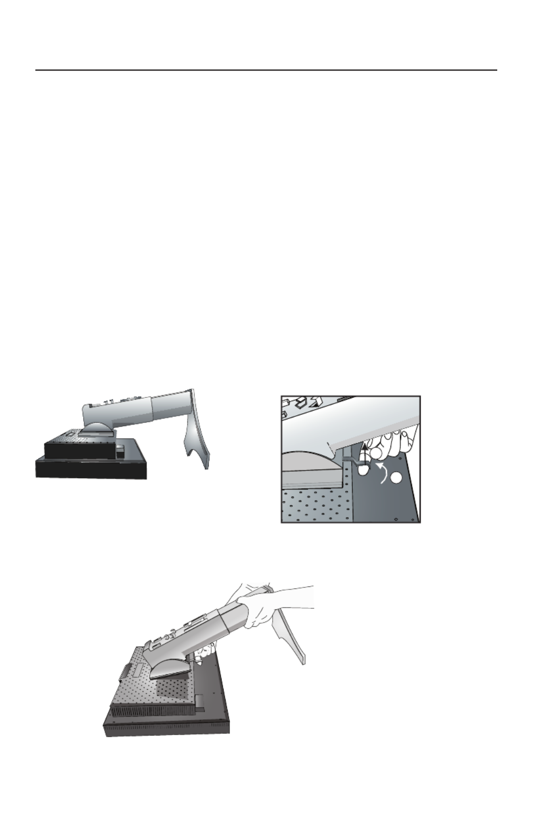
49
1
2
Retrait du support pour le montage
Le support peut être enlever pour monter le moniteur avec une autre méthode de
montage VESA, approuvée.
1. Déconnectez tous les câbles.
2. Placez les mains de chaque côté du moniteur en le relevant dans sa position la plus
haute. (voir Élévation et descente de l’écran du moniteur page 47).
3. Placez le moniteur avec l’écran vers le bas sur une surface non abrasive (Figure S.1).
4. Placez une main autour du support et l’autre sur le levier de dégagement rapide.
Déplacez le levier de dégagement rapide dans le sens indiqué par les fl èches.
(Figure S.2).
5. Relevez le socle du support pour le décrocher du moniteur (Figure S. 3).
Le moniteur peut maintenant être remonté en inversant le la méthode.
Inversez le processus pour remettre le socle en place.
REMARQUE : Prenez des précautions pour ôter le support du moniteur.
(Figure S.2)
Mise en train – Suite
(Figure S.1)
(Figure S.3)
1. Tirez le levier vers le stand.
2. Glissez le levier vers la droite.

50
Installation du bras fl exible
Ce moniteur ACL a été conçu pour être utilisé avec un bras fl exible. Montage
du moniteur sur bras fl exible :
1. Enlevez le support (voir Retrait du support pour le moniteur page 49).
2. Utilisez les 4 vis qui sont incluses pour fi xer le bras du moniteur (Figure F.1).
Mise en train – Suite
MISE EN GARDE : Utilisez uniquement les 4 vis qui sont incluses pour le montage
afi n d’éviter d’endommager le moniteur, le support ou le bras. Les
exigences sur la sécurité requièrent que le moniteur soit monté sur
un bras garantissant la stabilité de l’appareil et capable de
soutenir son poids. Le moniteur ACL ne doit être utilisé qu’avec
un bras approuvé (portant la marque GS).
L’utilisation d’accessoires de montage (ex. : VESA(200 x 100))
autres que VESA (100 x 100) requiertl’utilisation de vis M4 (lon
gueur : largeur du support+ 10 mm).
(Figure F.1)
100mm
100mm
200mm
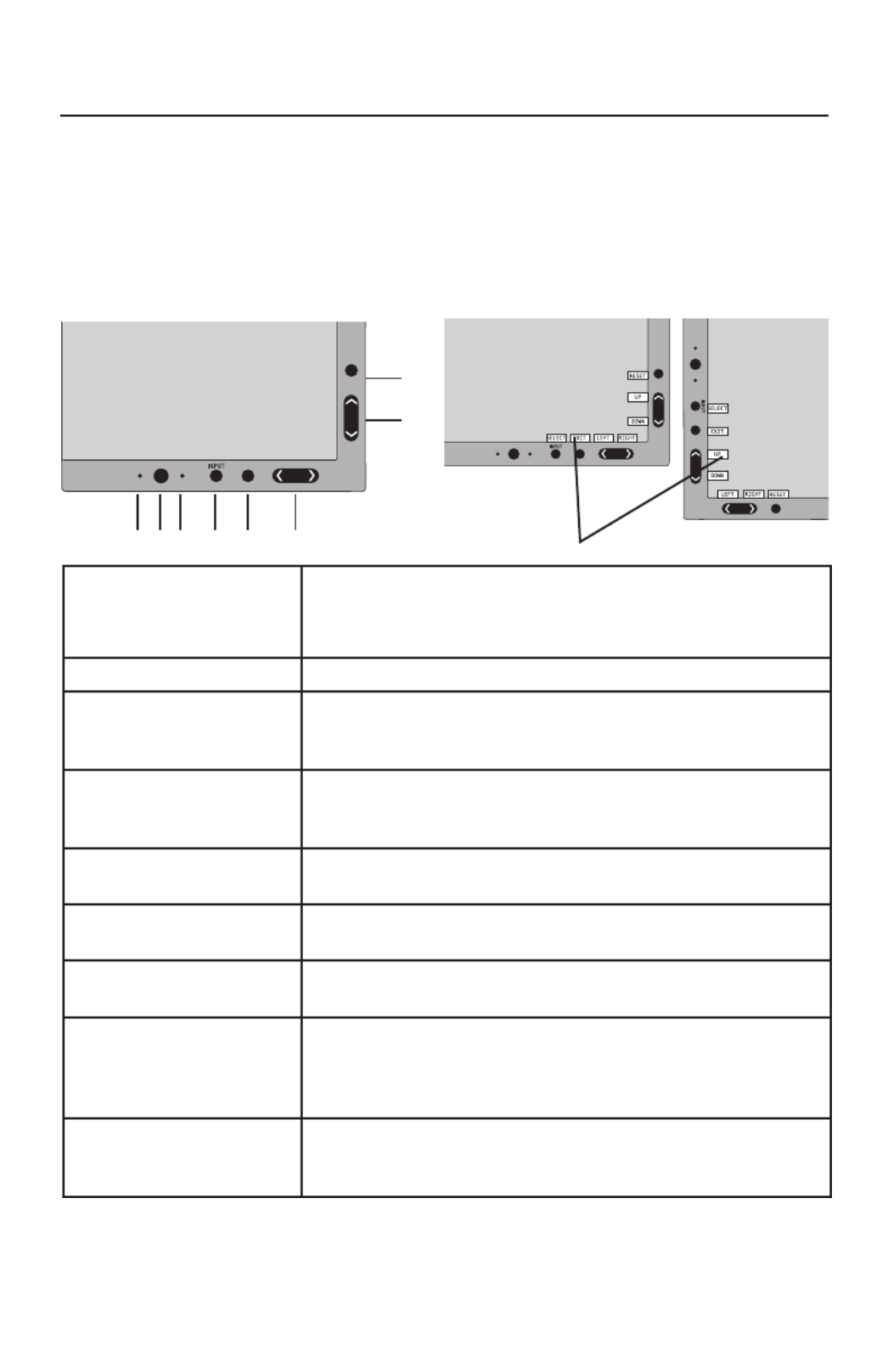
51
* les fonctionnalités des touches « GAUCHE/DROITE » et « HAUT/BAS » sont
interchangeables selon l’orientation (paysage/portrait) de l’OSM.
Commandes
1CAPTEUR AMBIBRIGHT Détecte le niveau de lumière ambiante permettant au
moniteur de faire des ajustements dans divers réglages pour
produire une vision plus agréable. Ne pas couvrir ce capteur.
2 ALIMENTATION Met le moniteur sous ou hors tension.
3 DEL Indique si l’appareil est sous tension.
Peut être changé entre bleu ou vert dans le menu des comman-
des OSM option-avancée
4 INPUT/SELECT
(ENTRÉE/SÉLECTION) Accède au menu de commande OSM. Entre dans les sous-
menus OSM Change la source d’entrée en dehors du menu
de commande OSM.
5 EXIT (QUITTER) Quitte le sous-menu OSM. Quitte le menu de commande
OSM
6 LEFT/RIGHT
(GAUCHE/DROITE) Navigue de gauche à droite dans le menu de commande
OSM.
7 UP/DOWN
(HAUT/BAS) Navigue de haut en bas dans le menu de commande OSM.
8 RESET/ROTATE OSM
(RÉINITIALISER/
ROTATION du OSM)
Réinitialise les réglages OSM aux paramètres effectués à
l’usine. à appuyer lorsque l’OSM ne semble pas changer le
menu de commande OSM entre le mode portrait et le mode
paysage.* voir la page 66 Tag9 « ROTATION du OSM ».
9 GUIDE DES ACCÈS Le guide des accès apparaît sur l’écran quand le menu des
commandes OSM est accessible. Le guide des accès tour-
nera quand le menu des commandes OSM est pivoté.
Commandes OSM (gestionnaire à l’écran)
Situés à l’avant du moniteur, fonctionnent de la manière suivante :
Pour accéder au menu OSM, appuyez sur une des touches de commande : EXIT,
GAUCHE, DROITE, HAUT, BAS
.
Pour changer le signal de source d’entrée quand l’OSM est fermé, appuyez sur la
touche de ENTRÉE/SÉLECTION.
1 2 3 4 5 6
7
8
9Portrait
Paysage

52
Commandes de luminosité/contraste
LUMINOSITÉ : Ajuste la luminosité globale de l’image et du fond.
CONTRASTE : Ajuste la luminosité de l’image par rapport au fond.
CONTRASTE AUTO. (Entrée analogique seulement) : Ajuste l’image affichée pour
les entrées vidéo non standard.
MODE ÉCO : Diminue le niveau d’énergie consommée en réduisant le
niveau de luminosité.
1: Diminue la luminosité de 25 %.
2: Diminue la luminosité de 50 %.
PERSO. : Diminue le niveau de
luminosité selon le choix de l’utilisateur. Consultez le menu OSM option-
avancée pour les instructions de réglage personnalisé.
LUMINOSITÉ AUTO. : Il existe trois réglages de luminosité automatique.
ARRÉT : La luminosité automatique ne fonctionne pas.
1: Ajuste la luminosité automatique en détectant le niveau de luminosité
de votre environnement et ajuste le moniteur selon le meilleur réglage
de LUMINOSITÉ (voir page 78 pour les explications du Ambibright),
donnant une vision plus confortable.
2: Ajuste le niveau de luminosité du moniteur pour de meilleurs réglages selon la
quantité de blanc affichée sur le moniteur. Cette fonction n’utilise pas le capteur de
luminosité de AmbiBright.
REMARQUE : Ne pas couvrir le capteur de luminosité de AmbiBright.
Lorsque « LUMINANCE AUTO » (Page 59, Tag1) est définie sur
MAR, cette fonction estdésactivée.
NIVEAU DE NOIR : Ajuste le niveau du noir.
Réglage auto (Entrée analogique seulement)
RÉGLAGE AUTO : Ajuste automatiquement la position de l’image et
les paramètres de la taille H et les paramètres de précision.
Commandes – suite
Termékspecifikációk
| Márka: | NEC |
| Kategória: | Monitor |
| Modell: | MultiSync LCD2490WUXI |
Szüksége van segítségre?
Ha segítségre van szüksége NEC MultiSync LCD2490WUXI, tegyen fel kérdést alább, és más felhasználók válaszolnak Önnek
Útmutatók Monitor NEC

9 Április 2025
11 Január 2025
1 Január 2025
1 Január 2025
1 Január 2025
14 Október 2024
11 Október 2024
9 Október 2024
5 Október 2024
3 Október 2024
Útmutatók Monitor
- Monitor Samsung
- Monitor PeakTech
- Monitor Sony
- Monitor Yamaha
- Monitor Fujitsu
- Monitor Acer
- Monitor LG
- Monitor Philips
- Monitor Pioneer
- Monitor Olympus
- Monitor SilverCrest
- Monitor Garmin
- Monitor RCF
- Monitor Bosch
- Monitor Panasonic
- Monitor Canon
- Monitor JVC
- Monitor Sharp
- Monitor Lenovo
- Monitor HyperX
- Monitor Toshiba
- Monitor Neumann
- Monitor Omron
- Monitor HP
- Monitor Hyundai
- Monitor Hisense
- Monitor BenQ
- Monitor Apple
- Monitor Emos
- Monitor Medion
- Monitor Vimar
- Monitor JBL
- Monitor TCL
- Monitor OSEE
- Monitor Viessmann
- Monitor Insignia
- Monitor LC-Power
- Monitor Dell
- Monitor Boss
- Monitor Crestron
- Monitor Gigabyte
- Monitor Tripp Lite
- Monitor Xerox
- Monitor Thomson
- Monitor Speco Technologies
- Monitor Hikvision
- Monitor Eurolite
- Monitor Epson
- Monitor V7
- Monitor Huawei
- Monitor Asus
- Monitor PEAQ
- Monitor Renkforce
- Monitor Haier
- Monitor Mitsubishi
- Monitor M-Audio
- Monitor AOC
- Monitor Citizen
- Monitor Westinghouse
- Monitor Hitachi
- Monitor Continental Edison
- Monitor Asrock
- Monitor Ring
- Monitor Alpine
- Monitor Optoma
- Monitor SPL
- Monitor Smart
- Monitor Dahua Technology
- Monitor Viewsonic
- Monitor Denver
- Monitor Dynaudio
- Monitor Ernitec
- Monitor Qian
- Monitor Joy-It
- Monitor MSI
- Monitor Daewoo
- Monitor Tesla
- Monitor Kali Audio
- Monitor Godox
- Monitor Cisco
- Monitor Newline
- Monitor Behringer
- Monitor APC
- Monitor KRK
- Monitor Cooler Master
- Monitor Chauvet
- Monitor Shure
- Monitor PreSonus
- Monitor Archos
- Monitor Deltaco
- Monitor Tannoy
- Monitor Plantronics
- Monitor Kogan
- Monitor Honeywell
- Monitor SMART Technologies
- Monitor Marshall
- Monitor Kindermann
- Monitor Alesis
- Monitor Velleman
- Monitor Prestigio
- Monitor Monacor
- Monitor IK Multimedia
- Monitor Blaupunkt
- Monitor NZXT
- Monitor Yealink
- Monitor Razer
- Monitor Samson
- Monitor Jay-Tech
- Monitor Mackie
- Monitor Posiflex
- Monitor Peerless-AV
- Monitor Abus
- Monitor AG Neovo
- Monitor Iiyama
- Monitor Konig
- Monitor Seiki
- Monitor 3M
- Monitor ARRI
- Monitor GlobalTronics
- Monitor Jensen
- Monitor Pyle
- Monitor AVer
- Monitor Sanyo
- Monitor Salora
- Monitor IFM
- Monitor DataVideo
- Monitor Maxell
- Monitor Atlona
- Monitor Schneider
- Monitor AJA
- Monitor Brandson
- Monitor Danfoss
- Monitor Vorago
- Monitor Barco
- Monitor Element
- Monitor Marshall Electronics
- Monitor Yorkville
- Monitor Elo
- Monitor IStarUSA
- Monitor Provision-ISR
- Monitor Postium
- Monitor Orion
- Monitor Palmer
- Monitor EverFocus
- Monitor Elvid
- Monitor Gamber-Johnson
- Monitor Focal
- Monitor Adj
- Monitor Legamaster
- Monitor Wohler
- Monitor Packard Bell
- Monitor Vitek
- Monitor Planar
- Monitor Mobile Pixels
- Monitor CSL
- Monitor Newstar
- Monitor SWIT
- Monitor RGBlink
- Monitor Kramer
- Monitor ART
- Monitor AMX
- Monitor Alienware
- Monitor Emachines
- Monitor Caliber
- Monitor Maxdata
- Monitor Sunstech
- Monitor Sunny
- Monitor BlueBuilt
- Monitor Marquant
- Monitor Da-Lite
- Monitor ProXtend
- Monitor Kubo
- Monitor GeoVision
- Monitor LaCie
- Monitor InFocus
- Monitor Midas
- Monitor Festo
- Monitor Swissonic
- Monitor Waeco
- Monitor Ikan
- Monitor IHealth
- Monitor QSC
- Monitor Hannspree
- Monitor ESI
- Monitor Avocor
- Monitor Simrad
- Monitor Jung
- Monitor Genelec
- Monitor Interlogix
- Monitor Eizo
- Monitor POSline
- Monitor Peerless
- Monitor Atomos
- Monitor Mad Catz
- Monitor Krom
- Monitor Monoprice
- Monitor Promethean
- Monitor Odys
- Monitor Fostex
- Monitor Prowise
- Monitor Terra
- Monitor Neets
- Monitor Stairville
- Monitor Soundstream
- Monitor Xoro
- Monitor HKC
- Monitor I3-Technologies
- Monitor CTOUCH
- Monitor Ozone
- Monitor HoverCam
- Monitor Ibm
- Monitor BOOX
- Monitor Aputure
- Monitor Drawmer
- Monitor Blue Sky
- Monitor Zalman
- Monitor Iadea
- Monitor Advantech
- Monitor Hercules
- Monitor Sonifex
- Monitor Avantone Pro
- Monitor Ganz
- Monitor Extron
- Monitor Belinea
- Monitor Adam
- Monitor Triton
- Monitor ITek
- Monitor Akuvox
- Monitor Antelope Audio
- Monitor MicroTouch
- Monitor X-Rite
- Monitor EKO
- Monitor ONYX
- Monitor IBoardTouch
- Monitor Mirai
- Monitor Elite Screens
- Monitor Mitsai
- Monitor Skytronic
- Monitor TV One
- Monitor Christie
- Monitor Hanwha
- Monitor COMMBOX
- Monitor Yiynova
- Monitor Pelco
- Monitor Lilliput
- Monitor LightZone
- Monitor AOpen
- Monitor Planet Audio
- Monitor EC Line
- Monitor Datacolor
- Monitor Fluid
- Monitor HELGI
- Monitor Desview
- Monitor Syscom
- Monitor Allsee
- Monitor Alogic
- Monitor Night Owl
- Monitor ProDVX
- Monitor Varad
- Monitor PureTools
- Monitor DoubleSight
- Monitor CTL
- Monitor Game Factor
- Monitor Nixeus
- Monitor Chimei
- Monitor Blue Sea
- Monitor AMCV
- Monitor Faytech
- Monitor Hamlet
- Monitor Wyse - Dell
- Monitor Approx
- Monitor Bauhn
- Monitor TVLogic
- Monitor Feelworld
- Monitor GeChic
- Monitor Oecolux
- Monitor ADS-TEC
- Monitor Satco
- Monitor Casalux
- Monitor Positivo
- Monitor Jupiter
- Monitor Transvideo
- Monitor Innocn
- Monitor KeepOut
- Monitor Shimbol
- Monitor Raysgem
- Monitor Motrona
- Monitor Ikegami
- Monitor AORUS
- Monitor Portkeys
- Monitor Mimo Monitors
- Monitor Enttec
- Monitor American Dynamics
- Monitor AIS
- Monitor Eve Audio
- Monitor Wortmann AG
- Monitor Viotek
- Monitor Vidi-Touch
- Monitor KTC
- Monitor CoolerMaster
- Monitor Atlantis Land
- Monitor HEDD
- Monitor Colormetrics
- Monitor Monkey Banana
- Monitor SmallHD
- Monitor UPERFECT
- Monitor GVision
- Monitor Voxicon
- Monitor Mybeo
- Monitor Bearware
- Monitor IOIO
- Monitor DTEN
- Monitor Cocopar
- Monitor Titan Army
- Monitor Xenarc
- Monitor Delvcam
- Monitor Wimaxit
- Monitor BookIT
Legújabb útmutatók Monitor

9 Április 2025

9 Április 2025

8 Április 2025
8 Április 2025

5 Április 2025

5 Április 2025

4 Április 2025

2 Április 2025
2 Április 2025

30 Március 2025