Használati útmutató JVC DT-V21G2Z
Olvassa el alább 📖 a magyar nyelvű használati útmutatót JVC DT-V21G2Z (37 oldal) a hangszóró kategóriában. Ezt az útmutatót 3 ember találta hasznosnak és 2 felhasználó értékelte átlagosan 4.5 csillagra
Oldal 1/37

MULTI FORMAT LCD MONITOR
INSTRUCTIONS
DT-V24G2
DT-V21G2
DT-V17G2
DT-V17G25
®
B5A-1245-00
The illustration of the monitor is of DT-V21G2.
This is the English instruction manual. Instruction manuals in other languages (German, French, Italian,
Spanish, Russian) are included on the supplied CD-ROM as PDF files (for Europe only).
For Customer Use:
Enter below the Model No. and Serial No.
which is located on the body. Retain this
information for future reference.
Model No.
Serial No.
:
:
Please read the following before getting
started:
Thank you for purchasing this product.
Before operating this unit, please read the
instructions carefully to ensure the best
possible performance.

22
Safety Precautions (English)
Before use, read “Safety Precautions” carefully, and then operate the product correctly.
FCC NOTICE
CAUTION: Changes or modifications not approved by JVC could void the user’s authority to operate the equipment.
NOTE: This equipment has been tested and found to comply with the limits for a Class A digital device, pursuant to Part 15 of the
FCC Rules. These limits are designed to provide reasonable protection against harmful interference when the equipment is operated
in a commercial environment. This equipment generates, uses, and can radiate radio frequency energy and, if not installed and used
in accordance with the instruction manual, may cause harmful interference to radio communications. Operation of this equipment in a
residential area is likely to cause harmful interference in which case the user will be required to correct the interference at his own expense.
CAN ICES-3A / NMB-3 A
Warning: This is a class A product. In a domestic environment this product may cause radio interference in which case the user may be required
to take adequate measures.
Use only the power source specified on the unit.
• AC power: 120 V/220 V – 240 V, 50 Hz/60 Hz
• DC power: 12 V – 17 V (DT-V21G2/DT-V17G2 only)
WARNING
To prevent injury by accidental fall
Fix the monitor to a wall by using strings.
Fixing the monitor
Attach the hook (not provided) to the VESA mounting holes on the
rear panel (use the two holes on the upper side) using M4 x 10
mm screws (not provided). Bind the hooks on the rear panel of the
monitor to a wall or a pillar using durable string.
Hook (not provided)
VESA mounting holes
The illustration of the monitor is of DT-V21G2.
Hook and screw (M4 x 10 mm)
(not provided)
EMC Supplement
This equipment is in conformity with the provisions and protection requirements of the corresponding European Directives. This equipment is
designed for professional video appliances and can be used in the following environments:
• Controlled EMC environment (for example purpose built broadcasting or recording studio), and rural outdoors environment (far away from
railways, transmitters, overhead power lines, etc.)
In order to keep the best performance and ensure electromagnetic compatibility, we recommend to use cables not exceeding the following length:
Cable Length
Power cord (attached cable (H05VV-F 3 x 0.75 mm
2)) 2.0 m
Video signal cable (coaxial cable) 2.0 m
Audio signal cable (shielded cable) 1.5 m
HDMI cable (shielded cable) 2.0 m
RS-232C cable (shielded cable) (A straight cable with a D-sub 9-pin connector) 2.0 m
RS-485 cable (twist pair cable) (A straight LAN cable) 2.0 m
REMOTE cable (twist pair cable) (A straight LAN cable) 2.0 m
CAUTION
In case where the strong electromagnetic waves or magnetism are near the audio cable or the signal cable, the sound or the picture will contain
noise. In such cases, please keep the cable away from the sources of the disturbance.
Product Fiche
Supplier
Model Name DT-V24G2 DT-V21G2 DT-V17G2 DT-V17G25
Energy Efficiency Class C C D D
Visible screen size 24 inch/61 cm 21.5 inch/55 cm 16.5 inch/42 cm 16.5 inch/42 cm
On-mode Power Consumption 38.9 W 38.8 W 29.0 W 29.7 W
Annual Energy Consumption*157 kWh 57 kWh 43 kWh 44 kWh
Stand-by mode Power Consumption 0.29 W 0.29 W 0.30 W 0.30 W
Resolution 1920 x 1200 pixels 1920 x 1080 pixels 1920 x 1080 pixels 1920 x 1080 pixels
*1 Energy consumption XYZ kWh per year, based on the power consumption of the television operating 4 hours per day for 365 days. The actual energy
consumption will depend on how the television is used.

33
Caution for use of the product for many hours
In the case that you use the monitor for many hours, we recommend that you set “No Sync Action” in “Sync Function” to “Power Save” in
Main Menu ( page 15). This will reduce power consumption and relieve strain on the monitor. To reduce damage to the LCD panel, +
using the LCD Saver function is recommended. ( page 16)+
Caution for use of the product in the high temperature
Do not use the product in places of high temperature; otherwise, parts of this product or the LCD panel may be damaged. This product is
equipped with a temperature sensor to give warning if the temperature becomes too high. If the temperature exceeds the range of normal
use, “Temp. Over” is displayed, and the power is turned off automatically if the temperature becomes any higher. In this case, move the
product to a place of low temperature to let it cool down.
Maintenance
Unplug this product from the wall outlet before cleaning.
LCD panel
To avoid irreparable change in appearance of the screen such
as uneven color, discoloration, scratches, be careful about the
following:
l Do not paste or stick anything using any glues or adhesive
tapes.
l Do not write anything on the screen.
l Do not strike the screen with a hard object.
l Avoid condensation on the screen.
l Do not wipe the screen with any liquid such as water. In
addition, wiping the screen with water-diluted neutral
detergent or solvent such as alcohol, thinner, or benzine may
affect the anti-reflection treatment of the screen.
l Do not wipe the screen forcefully.
Wipe stains off the LCD panel with a soft cloth. If the screen gets
heavily stained, wipe it with a soft cloth soaked in water-diluted
neutral detergent and wrung well, then wipe with a soft dry cloth.
Cabinet
To avoid the deterioration or damages of the cabinet such as its
paint’s peeling away, be careful about the following:
l Do not wipe the cabinet using solvent such as alcohol, thinner,
or benzine.
l Do not expose the cabinet to any volatile substance such as
insecticides.
l Do not allow any rubber or plastic in contact for a long time.
l Do not wipe the cabinet forcefully.
Wipe stains off the cabinet with a soft cloth. If the cabinet gets
heavily stained, wipe it with a soft cloth soaked in water-diluted
neutral detergent and wrung well, then wipe with a soft dry cloth.
Ventilation openings
Use a vacuum cleaner to get rid of the dust around the intakes (all
the openings). If a vacuum cleaner is not available, use a cloth and
wipe it off. Leaving the dust around the intakes may prevent proper
temperature control and cause damage to the product.
The LCD panel and backlight have life expectancy. Due to the basic characteristics of the LCD panel, an afterimage or uneven display
may occur. It is recommended that you change images occasionally, activate the power saving function, or often turn off the power to
reduce the load on the LCD panel. Continuous operations of the LCD panel may accelerate the deterioration.
Operating Precautions
Table of Contents
Safety Precautions (English) . . . . . . . . . . 2
Operating Precautions . . . . . . . . . . . . . . . 3
Caution for use of the product for many hours 3
Caution for use of the product in the high temperature 3
Maintenance 3
Installation ...........................4
Index of Parts and Functions . . . . . . . . . 5
Rear panel 5
Front panel 6
Showing Input Signals . . . . . . . . . . . . . . . 8
Audio Channel Selection 8
On the Information Display 8
On the Status Display 8
Menu Configuration . . . . . . . . . . . . . . . . . . 9
First Time Installation 9
The operation procedure 9
Menu Transition Diagram 10
Main Menu 11
Set-Up Menu 15
External Control . . . . . . . . . . . . . . . . . . . . .20
About the external control 20
Using the MAKE/TRIGGER system 20
Using the serial communication 21
Troubleshooting . . . . . . . . . . . . . . . . . . . .23
Self-check program 24
Specifications .......................25
General 25
LCD panel 25
Input/output terminals 25
Dimensions 26
Available signals 27
Sicherheitsmaßregeln (Deutsch) . . . . .28
Précautions de sécurité (Français). . . .29
Precauzioni di sicurezza (Italiano) . . . .30
Precauciones de seguridad (Español)
. . .31
Меры предосторожности (Русский)
. . .32
Указатель частей и функций . . . . . . .33

44
Installation
l How to set up 1
You can tilt the monitor as follows.
When the monitor is not tilted (0°),
the guidelines align as illustrated
below.
Guidelines
Stand
Monitor
Approx. 6°
0°
Approx. 6° The illustration of the
monitor is of DT-V21G2.
l Be careful not to pinch your fingers in the gap between the
monitor and the stand.
l How to set up 2
You can place the monitor as illustrated below.
1 Remove the screws on the sides of the stand (see the following
illustration), and lift up the stand.
Screw (silver) Approx.
141°
*1
*1
Approx. 148° for DT-V24G2.
2 Attach the removed screws and place the monitor as illustrated
below.
The illustration of the
monitor is of DT-V21G2.
l
To place the monitor as shown in “How to set up 1” again, remove
the screws on the sides of the stand, align the guidelines, and then
reattach the screws.
CAUTION
l When lifting up the stand...
- Lay the monitor on a cloth with the LCD panel facing down to
prevent the LCD panel from being damaged.
-
Be careful not to pinch your fingers in the moving parts.
l Make sure to lift the stand up so that the monitor will be
vertical; otherwise the monitor may fall over.
l Place the monitor on a mat to avoid scratching the table
surface.
l Do not rest your arm on the monitor or lean against the monitor.
l Do not touch the LCD panel when installing the monitor.
l Be sure to install the monitor securely to prevent the monitor from falling over, which may cause damage to the monitor or injury.
l To detach the stand
Lay the monitor on a cloth with the LCD panel facing down to
prevent the LCD panel from being damaged.
Attachment screws
Screw holes for stand
attachment Stand body
Monitor
The illustration of the
monitor is of DT-V21G2.
l To install the stand
When attaching the stand to the monitor, insert the guides of
the stand plate into the guide holes on the monitor to place the
stand in the correct position. Then fix the stand firmly with the
attachment screws.
Monitor
Screw holes for
stand attachment
Guides
Guide holes
Stand plate
Stand body The illustration of the
monitor is of DT-V21G2.

55
Index of Parts and Functions
1 REMOTE terminal
Terminal for controlling the monitor by an external control
( “External Control” on page 20).+
2 VIDEO terminals (BNC)
Input and output terminals for the composite signals.
3 COMPO. (Y, PB/B-Y, PR/R-Y) terminals (BNC)
Input terminals for the analog component (color difference) signal.
4 AUDIO ASSIGN (IN 1, IN 2) terminals (IN 1: pin jack, IN 2: Φ3.5mm)
Input terminals for the analog audio signals.
l Use this terminal for the analog audio connection of the SDI.
When a superimposed signal (EMBEDDED AUDIO signal on an
SDI signal) is input, analog audio signals cannot be input.
5 AUDIO ASSIGN (MONITOR OUT) terminals (pin jack)
Output terminals for the analog audio signal.
l The signal is output from this terminal only when the monitor is
on or in “Power Save” mode ( “No Sync Action” on page 15).+
l The EMBEDDED AUDIO signal...
–is decoded into an analog signal, then emitted.
–is emitted only when “SDI 1” or “SDI 2” is selected, and when
EMBEDDED AUDIO signals come in to the 3G/HD/SD SDI (IN 1
or IN 2) terminal.
l Audio signals are only output from the HDMI terminal when the
signals are not protected by HDCP.
–Even when the signals are protected by HDCP, sound is emitted
from the speakers.
6 3G/HD/SD SDI (IN 1, IN 2) terminals (BNC)
Input terminals for the 3G/HD/SD SDI signals.
l The terminals accept also EMBEDDED AUDIO signals including
up to 16 audio channels with a sampling frequency of 48 kHz.
l Use SDI IN 1 and SDI IN 2 terminal when selecting DUAL LINK
SDI for the input.
–Insert Link A into IN 1, and Link B into IN 2.
7 3G/HD/SD SDI (OUT 1, OUT 2: SWITCHED OUT) terminal (BNC)
Output terminal for the 3G/HD/SD SDI signals.
l For SDI OUT 1 output, the SDI IN1 signal is emitted.
l For SDI OUT 2 output, set the output signal in SDI2 OUT SEL of
the Main Menu ( “Signal Setting” on page 12).+
l
When an input other than SDI 1 and SDI 2 is selected, the SDI
signal of the input selected last time is emitted from this terminal.
l The signals are emitted from this terminal only when the
monitor is on or in “Power Save” ( page 15) mode.+
8 HDMI terminals
Input terminal for the HDMI signal compatible with HDCP.
Rear panel
9 Screw holes for external battery attachment (DT-V21G2/DT-
V17G2 only)
Attach external battery for DC power supply by using 2 screw
holes. Choose the appropriate screw holes from 1, 2 or 3 according
to the type of external battery. (Depending on the battery type.)
Use the Anton Bauer Dionic 90 (mount: QR DXC-M3A) external battery.
Caution:
Do not use the external battery for DC 24 V power supply.
Use only the battery specified above. If a heavy battery is used,
it may fall off depending on the way the monitor is used.
p DC switch (DT-V21G2/DT-V17G2 only)
Turns the DC power on or off.
l You need to press button ( on page 7) on the front +;
panel to turn on the monitor after turning on the DC switch.
l The monitor consumes the battery even while the monitor is on
standby. To save battery life, turn off the DC switch.
q DC IN terminal (DT-V21G2/DT-V17G2 only)
DC 12 V (maximum DC 17 V) power input
connector.
When using DC 12 V power (maximum DC 17 V), check the
DC IN terminal pin signal, and use the correct polarity. If the
polarity is reversed, this could cause a fire or personal injury.
l While using both the AC and DC power supply, AC power
supply is preferentially used. If the AC power supply is cut off
(for example, when turning off the POWER switch), the power
supply automatically switches to the DC power supply.
l
Use a DC power supply with the LPS (Limited Power Sources) function.
w AC IN terminal
AC power input connector. Connect the provided AC power cord
to an AC outlet.
l Attach the provided power cord holder to prevent accidental
disconnection of the AC power cord. ( page 24)+
l Attach the provided core filter. (North America only) ( page 24)+
Caution: Do not connect the power cord until all other
connections are completed.
e POWER switch
Turns AC power on or off.
l You need to press button ( on page 7) to use the +;
monitor after turning on the POWER switch.
Note for connections
• Beforemakinganyconnections,turnoffalltheequipment.
• Useacordwhoseplugscorrectlymatchtheterminalsonthismonitor
and the equipment.
• Plugsshouldbefirmlyinserted;poorconnectionscouldcausenoise.
• Whenunpluggingacord,besuretograspitsplugandpullitout.
• DONOTconnectthepowercorduntilallconnectionsarecomplete.
• Referalsototheusermanualofeachpieceofequipment.
Carry handle (DT-V21G2/DT-V17G2/
DT-V17G25 only)
Use this handle when carrying the monitor.
DT-V21G2/
DT-V17G2 only
Security slot
Attach a security wire to this slot.
The illustration of
the monitor is of
DT-V21G2.
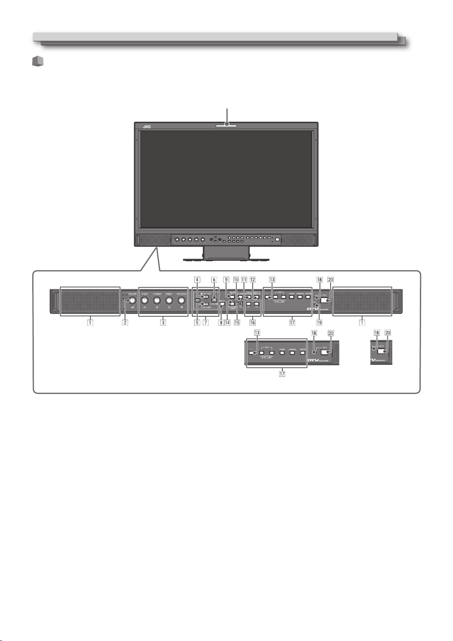
66
Index of Parts and Functions (cont.)
The illustration of the
monitor is of DT-V21G2.
Front panel
Tally lamp
This lamp is controlled by the tally function of the MAKE/TRIGGER terminal.
• Youcanselectthecolorofthetallylampfrom“Green”or“Red.”
You can also select whether the whole lamp is turned on at once, or whether it is turned on one half at a
time. ( “Tally Setting” in “Function Setting” on page 15 and “External Control” on page 20)+
• “NoEffect”isdisplayedwhenyoupressabuttonwhichisnotavailableforthecurrentinputorsignalformat(thelamplightsevenwhen
the function does not actually work).
• YoucannotusethebuttonsfortheitemscontrolledbytheMAKEsystem(“RemoteOn”appears,andthelampdoesnotlightup).
1 Speakers (stereo)
The speakers emit the same audio signal emitted from the AUDIO
ASSIGN (MONITOR OUT) terminals.
( “AUDIO ASSIGN (MONITOR OUT) terminals (pin jack)” on +5
page 5)
2 VOLUME adjustment knob
Adjusts the volume.
3 Picture adjustment knob
PHASE: Adjusts the picture hue
CHROMA: Adjusts the picture color density
BRIGHT: Adjusts the picture brightness
CONTRAST: Adjusts the picture contrast
l PHASE and CHROMA cannot be adjusted for certain signal
formats.
l When “Component Phase” is set to “Disable” and an NTSC
signal is input, PHASE can be adjusted ( page 15).+
4 MUTING button
Turns off the sound (Muting).
l To cancel the function, press the button again or turn the
VOLUME adjustment knob.
l Muting function is also canceled when “Balance” of “Audio
Setting” in the Main Menu is changed ( page 13).+
l Muting function cannot be activated when a menu screen is
displayed.
5 FUNCTION button
Assign functions to the F1 and F2 buttons when the menu is not
displayed. ( page 16)+
6 EMBEDDED AUDIO setting button
Selects an audio channel when EMBEDDED AUDIO signals are
contained in SDI input. ( “Audio Channel Selection” on page +
8)
DT-V24G2 DT-V17G25
1 e i ; - , and are common to
DT-V24G2, DT-V21G2, DT-V17G2 and
DT-V17G25.
The illustration of the monitor is of
DT-V21G2.

77
7 / / / buttons
When a menu screen is displayed selects or adjusts menu items.
( “The operation procedure” on page 9)+
l Pressing button while holding button displays the Set-Up
Menu ( “Menu Configuration” on page 9).+
8 MENU button
Activates/deactivates the display of the Main Menu
( “Menu Configuration” on page 9).+
9 COLOR OFF button/lamp
Displays only the luminance signal.
l This function does not work for RGB input signals.
p SCOPE button/lamp
Displays/hides the indication of the wave form monitor and vector
scope ( “Scope Setting” on page 14).+
l Each time you press this button, the window changes in the
following order.
Histogram
Wave form monitor
Vectorscope
No display
q AREA MARKER button/lamp
Displays/hides the area marker.
l
Select the style of the area marker in “Marker” of the Main Menu
( page 12).+
l This function works only when displaying the picture in 16:9
aspect ratio.
l
This function does not work when “Area Marker” or “R-Area
Marker” is set to “Off” in “Marker.”
w SAFETY MARKER button/lamp
Displays/hides the safety marker.
l Adjust the area of the safety marker in “Marker” of Main Menu
( page 12).+
l
This function will not work when the picture is displayed in 1:1
aspect ratio and “SD4:3 Size” on the menu is set to “H Full”.
l This function does not work when “Safety Marker” or “R-Safety
Marker” is set to “Off” in “Marker.
e 1:1 button/lamp
Displays the picture in the original resolution of the input signal.
l The aspect ratio of the picture may change depending on the
input signal.
r SCREENS CHECK button/lamp
Displays only the selected element (R, G, or B) of the video signal.
l This function does not work for RGB input signals.
l Each time you press this button, the picture changes in the
following order.
RGB (Normal screen) Red screen
Blue screen Green screen
t T.C. (time code) button/lamp
Activates/deactivates the display of the time data (time code)
contained in the SDI signal ( “On the Information Display” on +
page 8).
l Select the time code type in “Information” of Set-Up Menu
( page 17).+
y F1/F2 buttons/lamps
You can use the functions assigned to this button.
u INPUT SELECT buttons/lamps
Selects an input.
SDI 1: Input from the 3G/HD/SD SDI (IN 1)
terminal
SDI 2: Input from the 3G/HD/SD SDI (IN 2)
terminal
DUAL LINK: Input from the 3G/HD/SD SDI (IN 1, IN 2)
terminals
HDMI: Input from the HDMI terminal
COMPO.: Input from the COMPO. terminals
VIDEO: Input from the VIDEO terminal
l The lamp for the selected input lights.
i Power lamp
Unlit: The monitor is completely off (the POWER
switch on the rear panel is turned off) or in
Low Power Mode ( page 19)+
Lights in Green: The monitor is on
Lights in orange: The monitor is off (on standby)
Flashes in orange
: The monitor is in the Power Save (power
save) mode ( “No Sync Action” on page +
15)
o DC lamp (DT-V21G2/DT-V17G2 only)
When the DC power voltage is being lowered due to the battery
consumption, the lamp changes to orange from green. When the
voltage becomes lower than a certain level, the monitor
automatically turns off and the lamp turns to red.
l Make sure to turn off the POWER ( on page 5) switch +e
and DC ( on page 5) switch on the rear panel before +p
replacing the battery.
l The length of time that the lamp lights in orange differs
depending on the type of battery or the battery condition. It is
recommended to replace the battery when the lamp turns to
orange.
; button
Turns on and off (on standby) the monitor.
l To turn off the monitor completely, turn off the POWER switch
( on page 5) and DC switch ( on page 5).+e+p

88
Audio Channel Selection
Select the audio channel output from the Speaker and AUDIO ASSIGN (MONITOR OUT) (OUT1(L)/OUT2(R))
terminals when an EMBEDDED AUDIO signal is input during SDI input.
l Store the setting for each input of SDI 1 and SDI 2.
1 When the menu is not displayed, use the button
The “Embedded Audio” screen appears.
l The “Embedded Audio” screen disappears automatically is no operations are made for about 30 seconds.
2 Use the buttons to select the audio channel
3 Use the buttons to select the left and right channels (L ch/R ch/L ch+R ch)
l Each time you press a button the audio channel changes together with “Embedded Audio ch Setting”.
( page 13)+
4 Press the MENU button
l The “Embedded Audio” screen disappears.
On the Information Display
The monitor displays the information below.
l Make the setting to display/hide each information using the MENU with the exception of , controlled with T.C. button ( on page 7).5+t
1 Level meter
l You can check the conditions of the EMBEDDED AUDIO signals when “Level Meter Display”
is set to “Horizontal1” or “Horizontal2” or “Vertical.” (+ “Audio Setting” on page 13)
l Not displayed when “Audio Meter Display” is set to “Off” or “Lissajous”.
2 Signal format
l Displayed when “Status Display” is set to “On.” ( “Information” on page 17)+
l For the contents displayed, see “Available signals” on page 27 and “On the signal format” below.
3 Source name assigned in “Character Setting”( “Information” on page 17)+
l Displayed when “Source ID” is set to “On” or “Auto.” ( “Information” on page 17)+
l Displayed in large letters when “Status Display” is set to “Off” or “Auto.”
4 CRC error indication
l Displayed when “CRC Error” is set to “On.” ( “Information” on page 17)+
l A red square is displayed when an error occurs.
5 Time code
l Press T.C. button ( on page 7).+t
l When the input signal includes no time code, “TC – –:– –:– –:– –” is displayed ( “Information” on page 17).+
On the Status Display
If you press the INPUT SELECT button ( on page 7) currently lit, the status of the input signal and setting of MUTING are displayed for +u
about 3 seconds.
l Make the setting to display/hide the status in “Status Display” of the “Information”. ( page 17)+
l When “Status Display” is set to “Auto” or “On,” the status below is also displayed in the following cases:
– When you change the input
– When the signal condition of the current input changes
– When you turn on the monitor
l When “Status Display” is set to “On,” the signal format and “Picture Memory Mode” will remain
displayed 3 seconds after the status is displayed. If “Picture Memory Mode” is set to “Off”, it will not be displayed.
1 Signal format
l For the contents displayed, see “Available signals” on page 27 and “On the signal format” below.
On the signal format
The following messages appear depending on the type of input signals and their conditions.
When a HDMI signal protected with HDCP is input
When no video signal comes in
When a noncompliant video signal comes in
Ô
Ô
Ô
“*” (at the end of the indication)
“No Sync”
“Out of range”
2 Signal format of HDMI and VIDEO/COMPONENT input
Status indication of DUAL LINK/3G SDI signal information
l “DUAL LINK” appears when the Main Menu “Dual Link” ( page 12) is set to “On” in SDI input, and the 3G SDI signal information appears +
when the Main Menu “Dual Link” is set to “Off.”
Status indication of 3G SDI signal information
Following signal information can be displayed when a 3G SDI signal comes in.
3G A-1: Level A mapping structure 1
3G A-2: Level A mapping structure 2
3G A-3: Level A mapping structure 3
3G A-4: Level A mapping structure 4
3G B-DS1: Level B data stream 1
3G B-DS2: Level B data stream 2
3G B-DUAL: Level B DUAL LINK
3 Detailed information of 3G SDI/HD-SDI DUAL LINK signal input
l Displays the sampling structure/pixel resolution of the signal format.
l Displayed when the 3G SDI/HD-SDI DUAL LINK signal is input.
4 Setting of “MUTING”
l Only appears when in mute mode ( on page 6).+4
5 Displaying the Picture Memory Mode
l Mode-1, Mode-2 or Mode-3 appears ( on page 11).+
<EmbeddedAudio1/2>
Output1ch : L
Output2ch : L
Output3ch : L
Output4ch : L
Output5ch : L
Output6ch : L
Output7ch : L
Output8ch : L
Embedded Audio screen
Showing Input Signals
1080/59.94p
3GA-2
4:4:4RGB10bit
MutingOn
Mode-1

99
First Time Installation
When you turn on the power and the monitor, “First Time Installation” appears.
Start setting referring to the menu configuration.
For the setting items, see the pages below.
• “Language” + “Language” on page 17
• “No Sync Action” “Sync Function” on page 15+
• “No Operation Action” “No Operation Action” on page 15+
Setting procedure
1 Press to move the cursor to the setting item
2 Press to select the setting values
l Each time you press one of these buttons, the setting value changes.
3 Move the cursor to “Set”
4 Press to finish setting
l When you change the settings, a confirmation message appears.
Operate according to directions.
The operation procedure
1 Press the MENU button to display the Main Menu
To display the Main Menu
Ô Press the MENU button.
To display the Set-Up Menu
Ô Press the button while holding the button.
2 Use the buttons to select an item and press the button to
proceed to the next screen
l For some items, pressing the buttons adjusts the setting.
3 Use the buttons to select an item and use the buttons
to adjust the setting
4 Press the MENU button to finish operations
l Press the MENU button repeatedly until the menu screen disappears.
Main Menu
Selected item
Operation guide
Set-Up Menu
Ex.: When “Picture Function” in
the Main Menu is selected
Menu Configuration
l The menu screen disappears automatically if no operations are
made for about 30 seconds.
l Inoperable menus will be grayed out.
l Some items will not be displayed on the menu depending on the
selected input and signal format.
l “Closed Caption” is available for North America only.
< >FirstTimeInstallation
:English
:Off
:Off
Language
NoSyncAction
NoOperationAction
Set
<MainMenu>
PictureFunction ▶
Size/PositionAdjust▶
Aspect▶
Zebra▶
SignalSetting▶
Marker▶
AudioSetting▶
ScopeSetting▶
SyncFunction▶
NoOperationAction : Off
ClosedCaption▶
<Set-UpMenu>
FunctionSetting ▶
PictureSubAdjust▶
WhiteBalanceSetting▶
RemoteSetting▶
Information▶
ControlLock : Off
Language : English
SDIFormat : Auto
IMD▶
allreset
<PictureFunction>
Backlight : -02
Aperture : Off
ApertureLevel :
0
7
CTI : Normal
LTI : Hard
Gamma : 2.2
ColorTemperature : 6500K
PictureMemory▶
submenu
reset
<MainMenu>
PictureFunction ▶
Size/PositionAdjust▶
Aspect▶
Zebra▶
SignalSetting▶
Marker▶
AudioSetting▶
ScopeSetting▶
SyncFunction▶
NoOperationAction : Off
ClosedCaption▶
l Once the settings have been adjusted, this screen will not appear
again.
l The settings can be changed afterwards in Main Menu and Set-Up
Menu.
1010
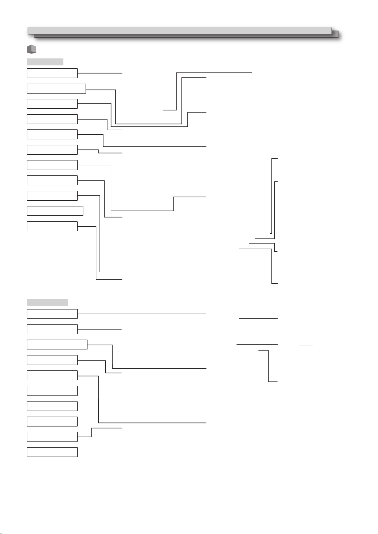
Menu Transition Diagram
Main Menu
Backlight
Aperture
Aperture Level
CTI
LTI
Gamma
Color mperatureTe
Picture Memory
sub menu
reset
Level Meter Display
Embedded Audio Group
Channel Arrange
Vertical Position
Horizontal Position
Meter peTy
Color
Reference Level
Over Level
Bar Brightness
Transparent
Peak Hold
H Axis Channel(X)
V Axis Channel(Y)
Position
Transparent
Gain
Delay
Input ch
Lissajous
Output 1ch - 16ch
H Size
H Position
V Size
V Postion
sub menu
reset
Picture Memory Mode
Save
Setting
HDMI Mode
3G SDI Level B
Dual Link
I/P Mode
Color System
SDI2 OUT SEL
sub menu
reset
Area Marker
Marker Aspect
Safety Marker
Safety Area
Frame
Center Marker
Line Brightness
R-Area Marker
R-Marker Aspect
R-Safety Marker
R-Safety Area
Auto Aspect
Manual Aspect
SD4:3 Size
1:1
16:9 Size *1
Zebra Mode
H-Level Threshold
L-Level Threshold
Balance
SDI-1 Select
SDI-2 Select
HDMI Select
Component Select
VIDEO Select
Audio Meter Display
Embedded Audio ch Setting
Level Meter Setting
Lissajous Setting
Audio Delay
No Sync Action
Delay meTi
Low Latency
Closed Caption
Data Format
Decode channel
Service Block
Gain
Size
Position
Transparent
Auto Off
Histogram Display
Wave Display
Wave Filter
Wave Over Level Marking
Wave Over Level
Picture Function
Audio Setting
Sync Function
No Operation Action
Closed Caption *2
Signal Setting
Marker
Aspect
Size/Position Adjust
Scope Setting
Zebra
Set-Up Menu
Contrast
Bright
Chroma
Phase
NTSC Setup
Component Level
sub menu
reset Color mperature *3Te
R Drive
G Drive
B Drive
R Cut Off
G Cut Off
B Cut Off
sub menu
reset
Function Setting
Picture Sub Adjust
White Balance Setting
Remote Setting
Information
Control Lock
Language
IMD
SDI Format
all reset
sub menu Position
Tally Setting
Dimmer
Component Phase
Color Gamut
Standby Mode
LCD Saver
Function Key Setting Setting
Execute
Cancel
Status
Start After
Tally peTy
Tally Color
1st Start
Work meTi
Contrast
Backlight
OSD Contrast
Side Mask
reset
Serial peTy
Parallel peTy
Pin1
Pin2
Pin3
Pin4
Pin5
Pin6
Pin7
Pin8 Source ID
Character Setting
Status Display
Time Code
CRC Error
Sub Hour Meter
Model
Version
Hour Meter
IMD Display
IMD Protocol
Address
IMD Size
IMD Position
Text Color
Tally 1 Color
Tally 2 Color
Background Color
reset
Function1
Function2
Function Display
*1 : DT-V24G2 only.
*2 : North America only.
*3 : “Color Temperature” is only displayed, and cannot be set/changed.
Menu Configuration (cont.)

1111
Main Menu
Picture Function
Setting for the picture quality.
Item To do Setting value
Backlight Adjusts the brightness of the display. –20 to +20
Aperture*1Activates/deactivates the function at the level set in “Aperture Level”. Off, On
Aperture Level*1Compensate the frequency response of the luminance signal of the video signal. 01 to 10
CTI Adjust the clearness of the outlines of the chrominance signal. Off, Normal, Hard
LTI Adjust the clearness of the outlines of the luminance signal. Off, Normal, Hard
Gamma Select the Gamma correction value. 2.2 is equivalent to Υ 2.2, 2.35 is equivalent to Υ 2.35,
2.45 is equivalent to Υ 2.45, 2.6 is equivalent to Υ 2.6.
2.2, 2.35, 2.45, 2.6
Color Temperature Select the color temperature. 9300K, 6500K, 5600K, User
Picture Memory Storage and retrieval of values set in “Picture Memory Mode,” “Save,” and “Setting”.
Picture Memory Mode*2Retrieves a stored setting value. Off, Mode-1, Mode-2, Mode-3
Save Save destination for a set value.
• Values set using the picture adjustment knob and values set in the “Picture Function”
menu are stored in “Picture Memory Mode”.
• Only selectable when “Picture Memory Mode” is set to “Off".
Mode-1, Mode-2, Mode-3
Setting Adjusts/stores the brightness, contrast, etc. of the picture.
• Selectable when “Picture Memory Mode“ is set to “Mode-1”, “Mode-2” or “Mode-3”.
Contrast Adjusts the level of the screen brightness. -128 to +127
Bright Adjusts black level. -128 to +127
Chroma Adjusts the color density. -128 to +127
Phase Adjusts the color phase. -128 to +127
Backlight Adjusts the back light brightness. -20 to +20
Aperture Activates/deactivates the function at the level set in “Aperture Level”. Off, On
Aperture Level
Compensate the frequency response of the luminance signal of the video signal. 01 to 10
Gamma*3Select the Gamma correction value. 2.2 is equivalent to Υ 2.2, 2.35 is equivalent to Υ 2.35,
2.45 is equivalent to Υ 2.45, 2.6 is equivalent to Υ 2.6.
2.2, 2.35, 2.45, 2.6
Color Temperature
*3Select the color temperature. 9300K, 6500K, 5600K, User
R Drive*4Adjust the drive level of each color (red, green, and blue).
• The maximum (Max) and minimum (Min) values vary depending on the input signal or
other settings
Min to 000 to Max.
G Drive*4Min to 000 to Max.
B Drive*4Min to 000 to Max.
Color Gamut
*
3Select the color reproduction range. ITU-709, User, Adobe RGB
sub menu Display the sub menu which enables you to adjust the items in “Picture Memory Setting” while viewing the actual picture.
Save Save destination for a set value.
• Stored in the currently selected “Mode-*”.
Restore Restore the stored values.
sub menu Display the sub menu which enables you to adjust the items in “Picture Function” while viewing the actual picture.
reset Restore the default settings for all the items in “Picture Function”.
l If the picture adjustment knob is operated while “Picture Memory Mode” is set to “Mode-1”, “Mode-2” or “Mode-3”, “sub menu” of “Setting” is
displayed and adjustment can only be performed using the buttons.
*1 Memorized for each input.
*2 When retrieving a setting value, “Mode-1”, “Mode-2” or “Mode-3” will be displayed on the status display.
When a value has been stored using “Save” after adjustment in “Setting”, or has not been restored to the stored value using “Restore”, “Mode-1*”,
“Mode-2*” or “Mode-3*” will be displayed.
*3 “Gamma”, “Color Temperature” and “Color Gamut” can only be set when “Picture Memory Mode” is set to “Mode-3”.
*4 “R Drive”, “G Drive” and “B Drive” can only be set when “Color Temperature” is set to “User”.
Size/Position Adjust
Adjusts the size and position of the picture.
Item To do Setting value
H Size* 1Adjust the horizontal picture size.
Setting value varies
depending on the signals.
H Position* 1Adjust the horizontal picture position.
V Size* 1Adjust the vertical picture size.
V Position* 1Adjust the vertical picture position.
sub menu Display the sub menu which enables you to adjust the items in “Size/Position Adjust” while viewing the actual picture.
reset Restore the default settings for all the items in “Size/Position Adjust”.
*1 Memorized for each signal format.
Aspect
Sets the aspect ratio of the screen for displaying videos.
Item To do Setting value
Auto Aspect Select whether to adjust the aspect ratio (horizontal to vertical ratio of the screen) of the SD
signal automatically or manually (Manual Aspect).
Off, On
Manual Aspect*1Sets the aspect ratio of the SD signal. 16:9, 4:3
SD4:3 Size* 1,*2Selects the picture size when the input signal format is 4:3. Normal, H Full, V Full*4
Normal : Matches the vertical picture size to the number of pixels.
H Full : Matches the horizontal picture size to the horizontal size of the screen. At
this time, the top and bottom of the picture are overscanned.
V Full*4: Enlarges the picture vertically.

1212
1:1*3Displays the picture in the original resolution of the input signal.
• The aspect ratio of the picture may change depending on the input signal.
Off, On
16:9 Size*1,*2,*4Selects the picture size when the input signal format is 16:9. Normal, V Full
Normal : Matches the vertical picture size to the number of pixels.
V Full : Enlarges the picture vertically. At this time, the right and left of the
picture are overscanned and markers are displayed.
*1 Not activate when picture is displayed in the 1:1 mode.
*2 When the histogram, wave form monitor or vector scope is displayed, only “Normal” is available.
*3 When the histogram, wave form monitor or vector scope is displayed, only “Off” is available.
*4 DT-V24G2 only.
Zebra
Settings for displaying the range of brightness.
Item To do Setting value
Zebra Mode Activate / deactivate the function. Off, On
H-Level Threshold
Setting the maximum brightness of an image for Zebra. “Over” means the range which exceeds 100%.
5% to 100% (by 5%), Over
L-Level Threshold Setting the minimum brightness of an image for Zebra. 0% to 100% (by 5%)
Signal Setting
Settings for input signals.
Item To do Setting value
HDMI Mode Settings for formats of signals input into the HDMI terminal.
• Automatically distinguishes signals when set to “Auto”. (Normally, select “Auto”)
• Select “Compo.”, “RGB” or “PC” when the picture is not displayed correctly with “Auto”.
• HDMI input of the monitor is compatible with HDCP.
Auto, Compo., RGB, PC
3G SDI Level B Selects the data stream from two HD SDI signals multiplexed when a 3G SDI LEVEL B signal
comes in.
• The setting value will be invalid if a 3G SDI LEVEL B DUAL LINK signal is input.
DS1, DS2
Dual Link Activates/deactivates the DUAL LINK function of SDI signals.
• “Dual Link” is displayed when the setting is set to “On”.
Off, On
I/P Mode Selects a proper mode corresponding to the input picture. Normal, Cinema
Color System Select the color system. Auto, NTSC, PAL, SECAM,
NTSC 4.43, PAL-M, PAL-N,
PAL60
• If the picture is unstable with “Auto”, select the color system according to the input signal.
SDI2 OUT SEL Specify output signal from the SDI OUT 2 terminal.
Switched Out : Signal of the currently selected SDI input (SDI 1 or SDI 2) is reclocked and
then output.
SDI-2 : Signal input from SDI IN 2 terminal is output.
Switched Out, SDI-2
sub menu Display the sub menu which enables you to adjust the items in “Signal Setting” while viewing the actual picture.
reset Restore the default settings for all the items in “Signal Setting”.
Marker*1
Settings for marker functions.
Item To do Setting value
1/2 Area Marker Activate/deactivate the area marker and select the style of it. Off, Line, Half, Half+Line
Off
Line
Half
Half+Line
:
:
:
:
Deactivate the marker.
Displays the area with an outline.
The area outside the specified aspect ratio of the screen is displayed at 50%
transparency.
The area of the specified aspect ratio of the screen is indicated by an outline,
and the area outside of that is displayed at 50% transparency.
Marker Aspect Select the aspect ratio of the area marker. 4:3, 16:9, 14:9, 13:9, 2.35:1,
1.85:1, 1.75:1, 1.66:1
Safety Marker Activate/deactivate the safety marker and select the style of it.* 2Off, Line, Half, Half+Line
Safety Area Adjust the area of the safety marker. 80% to 100%
Frame*3Displays/hides the video area. Off, On
Center Marker*3Displays/hides the marker indicating the center position of the picture. Off, On
Line Brightness Adjust the brightness of the marker. Low, High
2/2 R-Area Marker Activate/deactivate the area marker and select the style of it.* 2
Off, Line, Half, Half+Line
R-Marker Aspect Select the aspect ratio of the area marker. 4:3, 16:9, 14:9, 13:9, 2.35:1,
1.85:1, 1.75:1, 1.66:1
R-Safety Marker Activate/deactivate the safety marker and select the style of it.* 2
Off, Line, Half, Half+Line
R-Safety Area Adjust the area of the safety marker. 80% to 100%
l The area marker or the safety marker is displayed by using MARKER button or external control.
l “R” means “REMOTE (External control)”. Select either non-“R-” items or “R-” items to activate by using external control. ( “External Control” +
on page 20)
l When a picture is displayed in 4:3 aspect ratio, the safety marker for the 4:3 area is displayed.
l To display the safety marker for the area of a picture displayed in 16:9 aspect ratio, set Area Marker to "Off".
*1 Memorized for each input.
*2 The setting values are the same as that of “Area Marker”.
*3 In 1:1 mode, this display is grayed out and cannot be operated.
Menu Configuration (cont.)

1313
Audio Setting
Settings for AUDIO signals, EMBEDDED AUDIO signals and audio level meter signal.
Item To do Setting value
Balance Adjust the balance between the right and left speakers. L5 to L1, 0, R1 to R5
SDI-1 Select*1
SDI-2 Select*1
Select the input through which audio is output. Off, Auto, Digital, Analog1,
Analog2
Off
Auto
Digital
Analog1
Analog2
:
:
:
:
:
Does not output audio.
Output digital audio prior to analog audio.
Output audio from the SDI terminal.
Output audio from the AUDIO ASSIGN (IN 1) terminal.
Output audio from the AUDIO ASSIGN (IN 2) terminal.
HDMI Select Select the input through which audio is output. Off, Digital, Analog1,
Analog2
Off
Digital
Analog1
Analog2
:
:
:
:
Does not output audio.
Output audio from the HDMI terminal.
Output audio from the AUDIO ASSIGN (IN 1) terminal.
Output audio from the AUDIO ASSIGN (IN 2) terminal.
Component Select
VIDEO Select
Select the input through which audio is output. Off, Analog1, Analog2
Off
Analog1
Analog2
:
:
:
Does not output audio.
Output audio from the AUDIO ASSIGN (IN 1) terminal.
Output audio from the AUDIO ASSIGN (IN 2) terminal.
Audio Meter Display Specify whether to turn off Audio Meter Display, or display the Level Meter or Lissajous. Off, Level Meter, Lissajous
Embedded Audio ch Setting
*1Specify an EMBEDDED AUDIO CH.
Input ch Displays the currently selected SDI INPUT CH.
Lissajous Displays the EMBEDDED AUDIO CH selected from the Lissajous screen.
Output 1ch to 16ch Select a channel to output. L, R, LR, ---
Level Meter Setting*
2Specify the level meter display for EMBEDDED AUDIO signal.
Example of level meter display - Connection between the level meter position and channel
Ex: When “Horizontal1” is selected for “Level Meter Display”: Ex: When “Vertical” is selected for “Level Meter Display”:
-10dB -20dB-20dB -10dB
Reference
LevelOver Level
Green
Red Yellow
Over Level
Reference Level
-20dB
-10dB
• The number of audio channels displayed on the level meter varies depending on the setting value of “Embedded Audio
Group”.
• The level meter with no audio signal input is displayed in white for “3Colors”, and in gray for “White”.
• Display position
When “Horizontal 1” or “Horizontal 2” is selected for “Level Meter Display”, the display position will be the top or bottom
of the screen.
When “Vertical” is selected for “Level Meter Display”, the display position will be the lower right, lower left, upper left, or
upper right of the screen.
• When “On” is selected for “Peak Hold”, the maximum value is retained a certain period when the signal level becomes
maximum.
Level Meter Display Select the status of the level meter (display vertically or horizontally). Vertical, Horizontal1,
Horizontal2
Embedded Audio
Group*2
Select the audio channel group of the EMBEDDED AUDIO signals displayed on the level meter. 1G, 2G, 1-2G ,3G, 4G, 3-4G,
1-4G
1G
2G
1-2G
3G
4G
3-4G
1-4G
:
:
:
:
:
:
:
channel(s) 1/2/3/4
channel(s) 5/6/7/8
channel(s) 1/2/3/4/5/6/7/8
channel(s) 9/10/11/12
channel(s) 13/14/15/16
channel(s) 9/10/11/12/13/14/15/16
channel(s) 1/2/3/4/5/6/7/8/9/10/11/12/13/14/15/16
Channel Arrange
Select how the audio channels are displayed on the level meter.
Line, Divide
Vertical Position Adjust the vertical level meter position. Lower Right, Lower Left,
Upper Left, Upper Right
Horizontal Position Adjust the horizontal level meter position. Upper, Lower
Meter Type Specify the design of the level meter. Bar, Block
Color Select the color of the level meter display. 3Colors (colored depending on
the level), White (white only)
Reference Level Select the standard input level indicated on the level meter. –20dB, –18dB
Over Level Select the input level’s lower limit indicated in red for the “3Colors” display. –10dB, –8dB, –6dB, –4dB,
–2dB
Bar Brightness Select the brightness of the level meter. Low, High
1414
Transparent Adjust the transparency of the level meter display against the image. Off, Background, All
Peak Hold Activates/deactivates the peak hold function of the level meter. Off, On
Lissajous Setting Lissajous setting
<Lissajous display example>
H Axis Channel(X) Select an EMBEDDED AUDIO CH to display on the horizontal axis of the Lissajous screen. 1, 2, 3, 4, 5, 6, 7, 8, 9, 10, 11,
12, 13, 14, 15, 16
V Axis Channel(Y) Select the EMBEDDED AUDIO CH to display on the vertical axis of the Lissajous screen. 1, 2, 3, 4, 5, 6, 7, 8, 9, 10, 11,
12, 13, 14, 15, 16
Position Select a position to display the screen. Lower Right, Lower Left,
Upper Left, Upper Right
Transparent Set the background of the screen to translucent. Off, On
Gain Specify the Lissajous gain. 0dB, +6dB, +12dB
Audio Delay Audio delay setting
Delay Delay EMBEDDED AUDIO of SDI input. 0, 1, 2, 3, 4, 5, 6, 7, 8, 9, 10
*1 Operates as SDI-1 during Dual Link input.
*2 Memorized for each input.
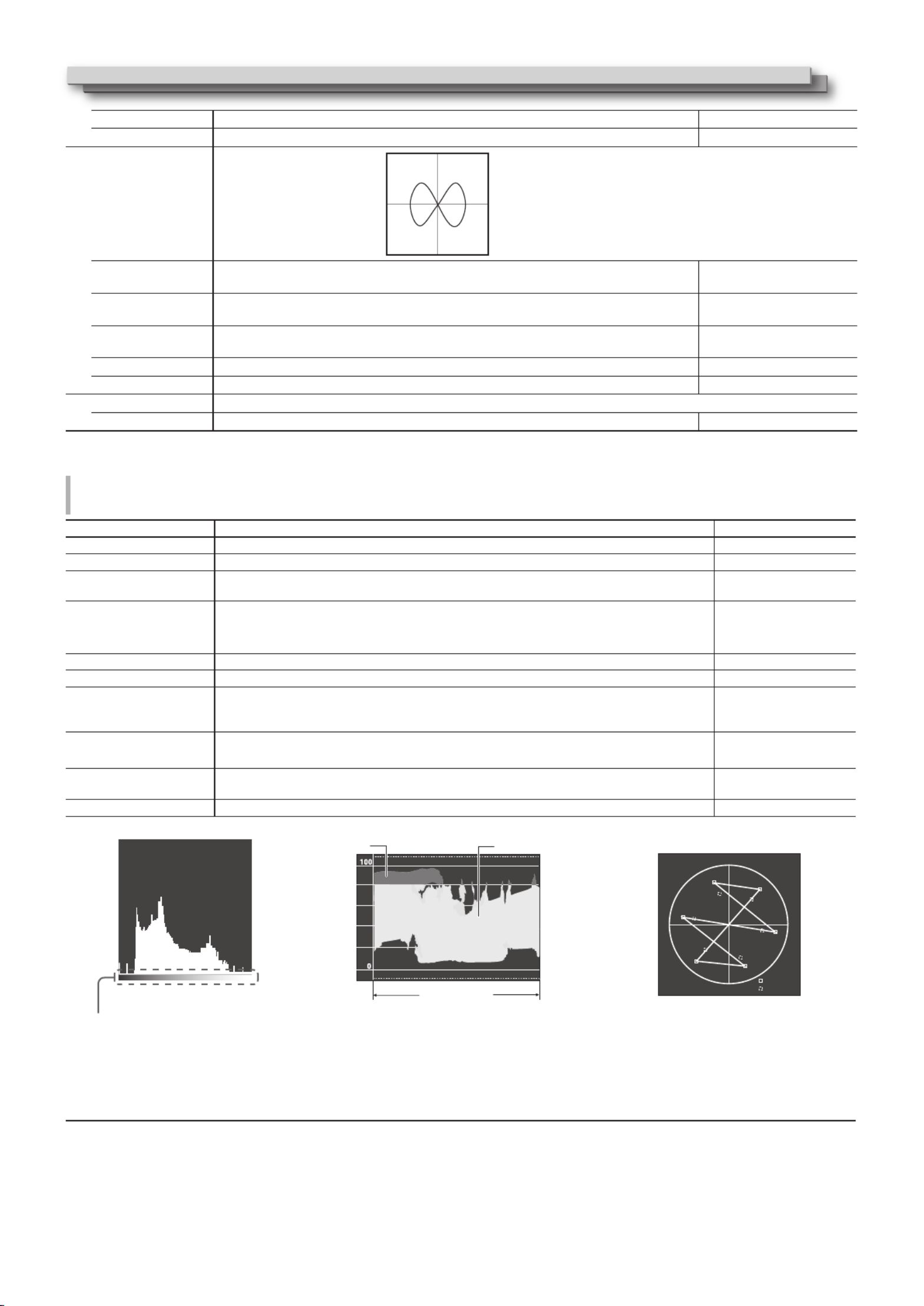
Scope Setting*1
Configure the settings for the wave form monitor, vector scope and histogram.
Item To do Setting value
Gain*2Adjust the input gain level. –10 to +10
Size*3Set the window size. Normal, Large
Position Select the window position. Lower Right, Lower Left
Upper Left, Upper Right
Transparent Activates/deactivates the function to make the window translucent. Off, On
Off
On
:
:
Normal
Translucent
Auto Off Set the function to turn off the window automatically 15 minutes after displayed. Off, On
Histogram Display Select the signal component for the histogram display. Y, R, G, B, RGB
Wave Display Select a wave form to be displayed for the wave form monitor. Y, Pb, Pr (HD signal)
Y, Cb, Cr (SD signal)
R, G, B (RGB signal)
Wave Filter Turn on/off the lowpass filter to put over the input wave form data. Flat (No filter)
Low pass
Wave Over Level Marking Turn on/off the function to change the wave form color of signals over the value specified in
“Wave Over Level”. ( below)+
Off, On
Wave Over Level Adjust the lower limit for the over level. 70 – 109
<Example of the histogram display> <Example of the wave form monitor> <Example of the vector scope>
<dark brightness light >
Pixels
Image signals
Start End
Red White
Y
Mg
R
B
100% level
75% level
Cy
G
Yl
The start and the end of the gradient
correspond to 0% and 100% of the signal.
Ex.: When the luminance signal is Y, “Wave Over
Level Marking” is set to “On” and “Wave Over
Level” is set to “80”
• Thewaveformcolorofsignalsoverthevalue
specified in “Wave Over Level” turns red.
• Thedisplaydiffersdependingontheinput
signal or the “Wave Display” setting.
Ex.: When the color bar is displayed
*1 The vector scope is not displayed when the input signals are RGB.
*2 Unavailable for the histogram.
*3 The size of the histogram can only be “Normal.”
Y
X
Menu Configuration (cont.)

1515
Sync Function
Settings for the synchronization with signals.
Item To do Setting value
No Sync Action Select the screen status when no signal is coming in. Off, Standby, Power Save
(power save mode),
Gray Back (gray screen)
Delay Time Select the period until the screen status changes as selected in “No Sync Action” after signals
stop coming in.
30s, 5min, 15min
Low Latency Activates/deactivates the function to shorten the time taken to display the picture (low
latency function).
Off, On
• If the picture is not displayed steadily while “On” is selected, select “Off.”
• While “On” is selected, the displayed picture may become unstable when an operation
using buttons on the front panel or the menu is performed, or when the signal format
changes.
l When setting “No Sync Action” to “Gray Back,” the screen color changes to gray and the power consumption of the backlight is saved by half.
Selecting “Power Save” (power save mode) saves more power consumption by turning off the backlight.
No Operation Action Setting values: Off, On
Setting of the function for turning the unit off (standby) automatically when no operations are made for more than 4 hours.
Off: Does not turn off automatically
On: Turns off automatically
l When the function is turned On, a warning message will be displayed about 3 minutes before turning off automatically.
When you turn on the unit with the function turned On, a message notifying that the setting is turned on will be displayed for about 30
seconds.
Closed Caption*1, *2
Settings for Closed Caption functions
Item To do Setting value
Closed Caption Activate/deactivate the closed caption. Off, On
Data Format Select the data format of closed caption. 708, 608ANC, 608(708),
608VBI*3
Decode channel Selects the type of closed caption. CC1, CC2, CC3, CC4, Text1,
Text2, Text3, Text4
Service Block Selects the type of service block. Service1, Service2, Service3,
Service4, Service5
• Closed Caption does not work for all video formats.
• Closed Caption does not work for the COMPO./HDMI input.
• Closed Caption does not work for the SDI input formats 1035/60i, 1035/59.94i, 1080/60p, 1080/59.94p, 1080/50p and 3G SDI Level A.
• Depending on signal format, there maybe a case that the closed captions are not displayed properly.
• When using the 1:1 mode, closed captions may not be displayed properly.
*1 North America only.
*2 Memorized for each input.
*3 Displayed only when SD SDI signal is input.
Set-Up Menu
Function Setting
Settings for the sub menu display, tally lamp, button lamp intensity, LCD Saver and FUNCTION button.
Item To do Setting value
sub menu Position Select the contents and displaying position of “sub menu.” Lower1, Upper1, Lower2,
Upper2
Lower1
:Displays the current setting and adjustment bar at the lower part of the screen.
Upper1
:Displays the current setting and adjustment bar at the upper part of the screen.
Lower2
:Displays the current setting at the lower part of the screen.
Upper2
:Displays the current setting at the upper part of the screen.
• The adjustment bar is not displayed for some items.
Tally Setting
Set the color and mode of the tally lamp using external control.
Tally Type Normal
Half
:
:
Light up the entire tally.
Light up the left and right halves of the tally individually.
Normal, Half
Tally Color Set the tally color when “Tally Type” is set to “Normal”. Green, Red
Dimmer Select the intensity of the button lamps. Normal, Dark
Component Phase Deactivates the function of PHASE adjustment (Picture adjustment knob and “Picture Sub
Adjust” in Set-Up Menu) except when an NTSC signal comes in ( on page 16).+
Enable, Disable
Color Gamut Select the color reproduction range. ITU-709, User, Adobe RGB

1616
Standby Mode Select the operation status when the monitor is powered OFF (standby). Normal, Serial, SDI Out
Normal
Serial
SDI Out
:
:
:
Changes to Low Power Mode 30 seconds after powered OFF to reduce power consumption.
In this case, it cannot power on by external control.
Can power on by external control after powered OFF.
Can power on by external control after powered OFF. Furthermore, video will
be output from the SDI OUT terminal.
LCD Saver Configure the setting for reducing damage to the LCD panel for long-time use. ( on page 19)+
Setting 1st Start Set the standby time. (unit: hours) 00h-24h
Work
Time
Set the time for performing the function. (unit: hours) 01h-06h
Contrast Set the contrast reduction. Normal, Save
Backlight Reduce the backlight brightness. Normal, Save
OSD
Contrast
Set the contrast reduction of the OSD display. Normal, Save
Side Mask Select whether to use the side mask.
* The Side Mask function works no matter whether the LCD Saver is active or stopped.
Off, On
reset Restore the default settings for all the items in “LCD Saver”.
Execute Execute the LCD Saver function.
Cancel Stop the LCD Saver function. (“Cancel” will be grayed out during the function stop.)
Status Display the LCD Saver status. Off, Ready
Start After Display required time until the LCD SAVER operation starts. (unit: hours and minutes) **h **min
Function Key Setting Specify the function assigned to the F1/F2 button.
Function1
Function2
Specify the function assigned to the F1/F2 button.
* For details on the functions set up, see the menu description (pages 11 to 18).
- - -, Aperture, I/P Mode,
Frame, Center Marker, Level
Meter Display, Gamma, Color
Temperature, CRC Error,
Manual Aspect, Picture
Memory Mode
Function Display Select whether to display the status of the assigned function when you press the F1 button. Off, Mode-1, Mode-2
Off
Mode-1
Mode-2
:
:
:
No status display. Perform the registration function.
Display the status. Perform the registration function.
Display the status. Do not perform the registration function.
Perform the registration function when the status is displayed and the button is
pressed again.
l To display the “Function Key Setting” menu, press the button when the menu is not displayed.
l About the operations of F1/F2 button
Each time you press the button, the setting value for the assigned function changes in order.
Ex: When “Color Temperature” is assigned
9300K 6500K 5600K User
Each time you press the button, four setting values alternate.
Picture Sub Adjust
Configure the standard level of image adjustment.
Item To do Setting value
Contrast*1Adjust the standard level for the contrast adjusted with the CONTRAST knob on the front
panel.
–20 to +20
Bright*1Adjust the standard level for the brightness adjusted with the BRIGHT knob on the front
panel.
–20 to +20
Chroma*1Adjust the standard level for the chroma adjusted with the CHROMA knob on the front panel. –20 to +20
Phase*1,
*2Adjust the standard level for the phase adjusted with the PHASE knob on the front panel. –20 to +20
NTSC Setup Select the set-up level of the input NTSC signal. 00 (compliant with 0 %
set-up signal), 7.5 (compliant
with 7.5 % set-up signal)
Component Level Select the level of the analog component signal (480i only). B75 (compliant with
BetacamVTR 7.5 % set-up
signal), B00 (compliant with
BetacamVTR 0 % set-up
signal), SMPTE (compliant
with M2VTR signals)
sub menu Display the sub menu which enables you to adjust the items in “Picture Sub Adjust” while viewing the actual picture.
reset Restore the default settings for all the items in “Picture Sub Adjust”.
*1 Memorized for each input.
*2 When “Component Phase” ( page 15) is set to “Disable,” “Phase” cannot be adjusted if no NTSC signal is input.+
Menu Configuration (cont.)

1717
White Balance Setting
Display the color temperature, and adjusts the drive level and cutoff point of each color (R/G/B).
Item To do Setting value
Color Temperature Select the color temperature. (Cannot be set/changed) 9300K, 6500K, 5600K, User
R Drive *
1
G Drive
B Drive
Adjust the drive level of each color (red, green, and blue).
• The maximum (Max) and minimum (Min) values vary depending on the input signal or
other settings.
Min – 000 – Max
(in 1024 grades)
R Cut Off *
1
G Cut Off
B Cut Off
Adjust the cutoff point of each color (red, green, and blue).
• The maximum (Max) and minimum (Min) values vary depending on the input signal or
other settings.
Min – 000 – Max
(in 1024 grades)
sub menu Display the sub menu which enables you to adjust the items in “White Balance Setting” while viewing the actual picture.
reset Restore the default settings for all the items in “White Balance Setting”.
*1 Memorized for each “Color Temperature”.
Remote Setting
Settings for the external control.
Item To do Setting value
Serial Type Select a terminal for external control in serial mode. RS232C, RS485
Parallel Type Select a control method of the MAKE/TRIGGER terminal. Make, Trigger, Set
Pin1
Assign the control functions to the pins of the MAKE/TRIGGER terminal.
• Assign a function to each pin terminal by selecting “Set” in “Parallel Type” mentioned
above.
+ “Display” in “Functions
controlled by the MAKE/
TRIGGER system” on page
21
Pin2
Pin3
Pin4
Pin5
Pin6 The functions are assigned for “Pin6” – “Pin8” and you cannot change the assignment of
these functions.
Tally
Pin7 Enable
Pin8 GND
Information
Settings for the information display of the monitor.
Item To do Setting value
Source ID Select whether the name assigned in “Character Setting” ( below) is displayed on the +
screen ( “On the Information Display” on page 8).+
• When “Auto” is selected, the display color synchronizes with the color of the tally lamp
while the tally lamp is lit.
Off, On, Auto
Character Setting Assign a name to each video source as you like (10 characters at maximum). You can also enter a name using the RS-232C
system. ( Page 19)+
Status Display Display/Hide the status of the current input and the setting of MUTING. ( “On the Status +
Display” on page 8)
Auto, Off, On
Time Code Select the type of the TIME CODE display.
VITC*1, LTC*1, D-VITC
CRC Error Display/Hide the CRC error when the HD SDI signal is input. ( “On the Information Display” +
on page 8)
Off, On
Sub Hour Meter Display the hours of use (unit: hour). The usage time can be reset to 0.
Model Display the model name of the monitor.
Version Display the version of the monitor.
Hour Meter Display the total hours of use (unit: hour). This item is used for maintenance of the monitor. You cannot reset this item.
*1 Ancillary time code
Control Lock Setting values: Off, Volume Lock, All Lock
Settings for disabling the buttons on the front panel.
• The following operations are not available when “Volume Lock” is selected.
- Picture adjustment knob
- VOLUME adjustment knob
• The “All Lock” function disables to control the buttons on the front panel. But following operations are available.
- Turning on/off (on standby) the monitor
- Displaying the Set-Up Menu by pressing button while holding button and turning “Control Lock” to “Off”
- Operating the monitor by an external control
If you try other operations, “Control Lock On!” appears on the screen.
Language Setting values: English, Deutsch, Français, Español, Italiano, Pуccкий
Select the displayed language for the menu, etc.
1818
SDI Format Setting value: Auto, MS1YCbCr, MS2YCbCr, MS3YCbCr, MS4YCbCr, MS2 RGB, MS3 RGB, 3G-B-DS
When “Auto” is selected, 3G SDI/HD-SDI DUAL LINK signals are automatically recognized. (Normally select “Auto.”)
l If the picture is unstable with “Auto”, select the setting value according to the input signal format.
l “M” (meaning “Manual”) is displayed on the status display when a setting other than “Auto” is selected.
IMD
Settings for IMD (In-monitor Display). ( Page 19)+
Item To do Setting value
IMD Display Display setting
Off : Not displayed
On : Displayed
Off, On
IMD Protocol
Serial communication protocol setting
Off : Supports JVC protocol
TSL V4.0 : Supports TSL UMD Protocol V4.0
Off, TSL V4.0
Address Address setting
000 to 126 : Set a particular address
000 to 126
IMD Size Text size setting
Small : Small size
Middle : Middle size
Large : Large size
Small, Middle, Large
IMD Position Specify the display position. Upper, Lower
Text Color Text color setting
Command : Same color as that set for communication (Command)
Red, Green, Amber, Blue, Cyan, Magenta, White : Color settings
Command, Red, Green, Amber,
Blue, Cyan, Magenta, White
Tally 1 Color Tally 1 color setting
Command : Same color as that set for communication (Command)
Red, Green, Amber, Blue, Cyan, Magenta, White : Color settings
Command, Red, Green, Amber,
Blue, Cyan, Magenta, White
Tally 2 Color Tally 2 color setting
Command : Same color as that set for communication (Command)
Red, Green, Amber, Blue, Cyan, Magenta, White : Color settings
Command, Red, Green, Amber,
Blue, Cyan, Magenta, White
Background Color Display background color setting
Black : Set the background of the IMD display to black.
Translucent : The picture on the monitor shows through the IMD display.
Transparent : Set the background of the IMD display transparent.
Black, Translucent, Transparent
reset Return the “IMD” settings to their default values.
all reset
Restores all the settings and adjustments of the monitor to the default.
l “Hour Meter” and settings specified using the Picture adjustment knob ( on page 6) are not reset.+3
Menu Configuration (cont.)

1919
l Setting of “Character Setting”
1 Change the input to one that you want to assign a video source name for.
2 Select “Character Setting”.
3 Press buttons to select the first character.
l Each time you press button, the character changes as follows.
Press button to reverse the order.
Space
Cha racterSetting
4 Press button to move the arrow to the next space.
l The characters entered before moving the arrow are memorized.
5 3 4 Repeat steps and (10 characters at maximum).
6 Press MENU button to store the name.
Cha racterSetting
l How to use the LCD Saver
1. Set reduced function to perform.
2. Set both time for starting the function and time for letting it work.
3. Activate the STANDBY MODE by Execute.
n Aborting the ongoing LCD Saver
Operating this apparatus may lead to aborting the OPERATION MODE.
n Stopping the operation
Executing “Cancel”. Turn off the power.
l Once operating the function, unless turned off the power or executed “Cancel”, reduced function is automatically performed every 24 hours.
n Example of setting up “1st Start” and “Work Time”
l IMD (In-monitor Display)
This unit supports “TSL UMD Protocol – V4.0” from Television Systems Ltd.
16 character text display and one tally on each side can be controlled.
The color of both the text and the tally can be set.
Using the address setting, up to 127 units can be controlled individually.
To use, set the external control terminals of this unit to serial format.
For details of control commands, refer to the homepage of Television Systems Ltd.
l Low Power Mode
Puts the unit into Low Power Mode 30 seconds after the monitor is switched off (standby) to further reduce power consumption.
• Low Power Mode will not activate when “Standby Mode” on the Set-up Menu is set to “Serial” or “SDI Out”.
• The power lamp will be turned off during Low Power Mode.
Time to set in
the 1st Start
0h 2h 4h 6h 8h 10h 12h 14h 16h 18h 20h 22h 24h
Timing to run "Execute"
LCD Saver in
standby
LCD Saver in
operation
Time to set in
Work Time
CAM-01
Text display area
* Example of lower screen IMD display
Tally 2Tally 1
LCD Saver in
standby

2020
External Control
About the external control
This monitor has two external control terminals.
l (RJ-45): The following external control MAKE/TRIGGER terminal
systems are available.
(1) MAKE (make contact) system:
Controls the monitor by short-circuiting the corresponding pin
terminal to the GND pin terminal, or disconnecting (opening) it.
(2) TRIGGER (trigger) system:
Controls the monitor by sending the pulse signal instantaneously
to the corresponding pin terminal.
“Using the MAKE/TRIGGER system”on the right+
l (RJ-45): Controls the monitor with the RS-485 RS-485 terminal
system. ( “Using the serial communication” on page 21)+
l (D-sub 9-pin): Controls the monitor with the RS-RS-232C terminal
232C system. ( “Using the serial communication” on page 21)+
Set the following items of “Remote Setting” in Set-Up Menu
according to the external control terminal and control system.
( “Serial Type,” “Parallel Type” on page 17)+
Control
terminal Control system
The settings of this unit
“Serial
Type”
setting
“Parallel
Type”
setting
MAKE/
TRIGGER
terminal
Parallel Type
MAKE — Make
TRIGGER — Trigger
RS-485
terminal
Serial
communication
RS-485 RS485*1—
RS-232C
terminal RS-232C RS232C*1—
*1 For a monitor connected to a personal computer etc, select the
terminal the equipment is actually connected to. For other monitors,
select “RS485.”
“MAKE” takes precedence over other controls.
l You can use external control even when “Control Lock” is set to
“Volume Lock” or “All Lock”. ( page 17)+
l When the monitor is off (on standby), external control is not
available. But certain external controls (starting/terminating
communication, turning on the monitor) are available through the
serial communication. ( page 22)+
<MAKE/TRIGGER system>
You can control the monitor by a personal computer or dedicated
controller*2.
l For the details, see “Using the MAKE/TRIGGER system” on the right.
*2 The controller is not commercially available. Consult your dealer if
you need it.
<Serial communication>
PC, etc.
RS-485
IN
RS-485 IN
or
RS-232C
RS-485
OUT
RS-485
IN
RS-485
OUT
RS-485
OUT
l For the details, see page 21.
Using the MAKE/TRIGGER system
The MAKE/TRIGGER terminal is configured as follows.
You can assign a function to each pin terminal in “Remote Setting”.
( “Pin1, Pin2, Pin3, Pin4, Pin5” in “Parallel Type” on page 17)+
l You cannot change the functions assigned to the pin terminals
from 6th to 8th.
Pin No. Pin name
1 Pin1
2 Pin2
3 Pin3
4 Pin4
5 Pin5
This is a female terminal. 6 Tally*1
7 Enable*2
8 GND
*1 The 6th pin terminal controls turning on or off the tally lamp
(available to control even when the 7th pin terminal is invalid).
*2 The 7th pin terminal makes the external control valid/invalid. Keep
the 7th pin short-circuited to 8th pin to make the external control
valid.
To assign the functions to the pin terminals
For the operation procedure, see page 9.
1 Select “Remote Setting” on the Set-Up Menu.
2 Set “Parallel Type” to “Set.”
3 Select a pin name (“Pin1” – “Pin5”) for which you want to assign a
function, then select the function you want to assign.
For the selectable functions, see the table on page 21.
Operation of the external control
1 Set “Parallel Type” of “Remote Setting” to “Make” or “Trigger” in the
Set-Up Menu.
2 Keep the 7th pin terminal (Enable) short-circuited to the 8th pin
terminal (GND) so that the monitor can be controlled by the external
control.
3 When the “MAKE” system is selected: Operate each function by short-
circuiting the corresponding pin terminal to the 8th pin terminal
(GND) or opening it.
When the “TRIGGER” system is selected: Operate each function by
pulse control, that is short-circuiting the corresponding pin terminal
to the 8th pin terminal (GND) for about 1 second and opening it.
l When changing the input with MAKE system, activate the pin you
want after deactivating the currently used pin.
l When selecting the “TRIGGER” system, you can operate only one
function at a time. Operate the functions one by one.

2121
<Functions controlled by the MAKE/TRIGGER system>
Display Functions to be controlled Opening Short-circuiting
– – – No function — —
Tally Color Tally lamp color selection*1Green Red
Tally Type Tally lamp lighting method selection Whole One half at a time
Tally-L(R) Light the left half of the tally lamp in red* 2Off On
Tally-R(G) Light the right half of the tally lamp in green* 2Off On
SDI-1 Changes the input to “SDI 1” Invalid Valid
SDI-2 Changes the input to “SDI 2” Invalid Valid
HDMI Changes the input to “HDMI” Invalid Valid
Compo. Changes the input to “Compo.” Invalid Valid
Video Changes the input to “Video” Invalid Valid
Area Marker The area marker indication Off On
Safety Marker The safety marker indication Off On
Center Marker The center marker indication Off On
Frame Indication of the area of the specified aspect ratio Off On
Marker Select Selects the items of “Marker”* 3Non-“R-” items “R-” items
Manual Aspect Changes the aspect ratio 4:3 16:9
1:1 Displays in 1:1 mode Off On
Status Status display*4+ “On the Status Display” on page 8
Level Meter Level meter display * 5
Time Code Time code display Off On
Source ID + “Source ID” in “Information” on page 17 *6
Color Off Color off Color Monochrome
Screens Check Screens check * 7
I/P Mode Change a mode according to a input picture * 8
Muting Muting on/off Off On
Dimmer Change the intensity of the button lamps Normal Dark
Wave Form Wave form monitor display Off On
Vector Scope Vector scope display Off On
Histogram Histogram display Off On
Zebra Mode Zebra mode Invalid Valid
*1 Can be controlled when “Tally Type” (“Set-Up Menu” “Function Setting” “Tally Setting”) is set to “Normal”.Ô Ô
*2 Can be controlled when “Tally Type” (“Set-Up Menu” “Function Setting” “Tally Setting”) is set to “Half”.Ô Ô
*3 Selects which functions in “Marker” are activated, non-“R-” items or “R-” items. ( “Marker” on page 12)+
*4 Displays the information shown when INPUT SELECT button of the current input is pressed. ( “On the Status Display” on page 8) While +
controlling with the MAKE system, the information is displayed only at the moment of short-circuiting.
*5 While controlling with the MAKE system, the level meter is switched between displayed (short-circuiting) and hidden (opening). When “Audio Meter
Display” is set to “Off” or “Lissajous” the level meter is not displayed (“No Effect” appears).
While controlling with the TRIGGER system, the pattern of the audio channel display is switched.
*6 While controlling with the MAKE system, the available set-up options will be the setting value currently selected in “Source ID” (“On” or “Auto” [short-
circuiting]) and “Off” (opening). While controlling with the TRIGGER system, uses the same set-up option as those in the Set-Up Menu. ( “Source ID” +
in “Information” on page 17)
*7 While controlling with the MAKE system, the screen is switched between normal screen (opening) and blue screen (short-circuiting). While
controlling with the TRIGGER system, the screen changes in the same way as when pressing SCREENS CHECK button ( on page 7).+r
*8 Must be controlled with the TRIGGER system. The mode is switched between “Normal” and “Cinema”. (This function cannot be controlled with the
MAKE system.)
l You cannot assign the same function to different pin terminals.
l The TRIGGER system switches each function by short-circuiting the pin terminal for about 1 second and opening it.
Using the serial communication
You can control the monitor from a personal computer etc. via the RS-485 or RS-232C terminal.
* Consult your dealer for the details of the external control specification.
<Communication specifications>
Input terminal Cable Terminal specification Communication specifications
RS-485 A straight LAN cable
+ page 22
Baud Rate: 4800 bps Stop Bits: 1 bit
Data Bits: 8 bits Flow Control: No control
Parity: No parity Communication Code: ASCII Code
RS-232C A straight cable with a D-sub 9-pin
connector (male for the monitor,
female for the personal computer etc.)

2222
<Specifications of the RS-485 terminal>
Pin No. IN terminal signal OUT terminal
signal
1 TXD + TXD +
2 TXD – TXD –
3 RXD + RXD +
4 NC NC
This is a female
terminal.
5 NC NC
6 RXD – RXD –
7 NC NC
8 GND GND
<Specifications of the RS-232C terminal>
Pin No. Signal
1 NC
2 RXD
3 TXD
4 NC
5 GND
This is a female
terminal.
6 NC
7 RTS
8 CTS
9 NC
l The 7th terminal and the 8th terminal are connected.
<Command outline>
All commands consist of the following segments.
Header Monitor ID Function Data Cr (0Dh)
On Header
“!” : Operation commands from the personal computer, etc. ( <Basic command list> below table).+
“?” : Reference commands from the personal computer, etc.
“@” : Status returns from the monitor
To start communication, send the connection command from the personal computer etc.
To terminate the communication, send the termination command from the personal computer etc.
Example of communication procedures
1 Starting the communication:
connection command (!00BCN1Cr)
3 Selecting “SDI 1” input (!00BINACr)
5 Terminating the communication:
termination command (!00BCN0Cr)
6 Monitor’s status (@00BOKCr)
4 Monitor’s status (@00BOKCr)
2 Monitor’s status (@00BOKCr)
PC, etc.
Monitor
<Basic command list>
No. Commands Functions Data
1! * **1B C N O Cr Terminates communication (termination) No data
2! * **1B C N 1 Cr Starts communication (connection) No data
3! * **1B I D S E T x x*2Cr Assigns the control ID 00-99
4! * **1B I D R E T Cr Initializes the control ID No data
5! * **1B I D D S P x x*2Cr Displays/hides the control ID 00: Hide, 01: Display
6! * **1B M E N U Cr Displays the Main Menu/Quits the menu operation No data
7! * **1B U P Cr Moves the cursor upward ( ) No data
8! * **1B D O W N Cr Moves the cursor downward ( ) No data
9! * **1B A D J R Cr Makes setting/adjustment ( ) No data
10 ! * **1B A D J L Cr Makes setting/adjustment ( ) No data
11 ! * **1B S E T U P Cr Displays the Set-Up Menu No data
12 ! * **1B P W O Cr Turns off monitor power control No data
13 ! * **1B P W 1 Cr Turns on monitor power control No data
14 ! * **1B I N A Cr Selects “A SDI1” input No data
15 ! * **1B I N B Cr Selects “A SDI2” input No data
16 ! * **1B I N C Cr Selects “C HDMI” input No data
17 ! * **1B I N D Cr Selects “D COMPO.” input No data
18 !* **1B I N E Cr Selects “E VIDEO” input No data
19 !* **1B D I S P Cr Displays signal status*3No data
20 !* **1B A M U T E x x*2Cr Turns muting on/off 00: Off, 01: On
21 ! * **1B A S P x x*2Cr Switches ASPECT (direct) 00: 4:3, 01: 16:9
l “Cr” is 0Dh.
l The commands for starting communication (connection) (No. 1), terminating communication (termination) (No. 2), and turning on the
monitor (No. 9) can be used while the monitor is off (on standby) when “Standby Mode” is set to “Serial” or “SDI Out”.
*1 Enter the monitor’s ID for “ **.” The initial setting of the monitor’s ID is “00.” When connecting several monitors, “00” is a command for controlling all
monitors at once.
*2 Enter the appropriate data to “xx.”
*3 Displays the information shown when the INPUT SELECT button currently lit is pressed. ( “On the Status Display” on page 8)+
External Control (cont.)

2323
Troubleshooting
Solutions to common problems related to the monitor are described here. If none of the solutions presented here solve the problem, unplug the
monitor and consult an authorized dealer or service center.
Symptom Probable cause and corrective action Page
No power supply.
l Press the button.
l (DT-V17G2/DT-V21G2 only) Firmly insert the AC power plug or DC power plug.
l (DT-V17G2/DT-V21G2 only) Turn on the POWER switch or DC switch on the rear
panel.
l (DT-V17G25/DT-V24G2 only) Firmly insert the AC power plug.
l (DT-V17G25/DT-V24G2 only) Turn on the POWER switch on the rear panel.
l When using a DC power supply, charge the battery or replace it with a charged one.
7
5
5
5
5
5
No picture with the power on.
l Select the correct input using the INPUT SELECT buttons.
l Connect the connecting cable firmly.
l Turn on the power of the connected component and set the output correctly.
l Check whether the input signal format is acceptable on the monitor.
7
5
—
27
No sound.
l Adjust the volume level.
l Deactivate the muting function.
l Connect the connecting cable firmly.
l Turn on the power of the connected component and set the output correctly.
l Set the correct inputs for “SDI-1 Select”, “SDI-2 Select”, “HDMI Select”, “Component
Select” and “Video Select” in “Audio Setting”.
6
6
5
—
13
“Out of range” appears. l Check whether the input signal format is acceptable on the monitor. 8, 27
“No Sync” appears.
l Select the correct input using the INPUT SELECT buttons.
l Connect the connecting cable firmly.
l Turn on the power of the connected component and output video signals. Or,
check whether the video output of the component (video output setting of the VCR
or graphic board of the computer) is set correctly.
7
5
—
Wrong color, no color.
l Adjust each picture adjustment knob on the front panel or adjust the items of
“Picture Sub Adjust” in the Set-Up Menu. Or, perform “reset” in “Picture Sub Adjust.”
l Check whether the setting of COLOR OFF or SCREENS CHECK buttons are
appropriate.
l Select the proper color system (“Color System”) in “Signal Setting”.
l Adjust the items of “White Balance Setting” in the Set-Up Menu. Or, perform “reset”
in “White Balance Setting”.
6, 16
7
12
17
The picture becomes blurred.
l Adjust the picture contrast or brightness by using the adjustment knobs on the
front panel. Or, adjust “Contrast” or “Bright” of “Picture Sub Adjust” in the Set-Up
Menu.
6, 16
Wrong picture position, wrong picture size.
The picture may sometimes not be able to fill
the whole screen depending on the signal. In
this case, nothing can be done to solve the
problem. Please be aware of this beforehand.
l Check whether the setting of 1:1 is appropriate.
l Check the “Aspect” settings in the Main menu.
l Check whether the input signal format is acceptable on the monitor.
l Adjust the picture size (H Size/V Size) or position (H Position/V Position) of “Size/
Position Adjust” menu.
7
11
27
11
Buttons on the monitor do not work.
l Set “Control Lock” in the Set-Up Menu to “Off.”
l You cannot use the buttons for the items controlled by the MAKE system. Disable
the external control.
17
20
The following are not malfunctions.
l When a still image is displayed for a long time, it may remain indistinctly on the screen after the picture has changed. Though the remaining
picture will disappear after a while, there may be a case that it remains for a long period depending on the length of time the still image was
displayed for. This is due to the characteristics of the LCD display and is not a malfunction.
l Red spots, blue spots and green spots on the panel surface are a normal characteristic of LCD panel, and not a problem. The LCD panel is built
with very high precision technology; however, be aware that a few pixels may be missing or constantly lit.
l The following symptoms are problems only when pictures or sounds are not played back normally.
l A slight electric shock occurs when you touch the LCD panel.
l The top and/or rear panel of the monitor becomes hot.
l The monitor emits a cracking noise.
l The monitor emits a mechanical noise.

2424
Self-check program
This monitor has a self-check function, which allows it to detect malfunctions and alert you. This makes troubleshooting easier. Whenever a
problem occurs, one or some of the INPUT SELECT lamps will flash.
If this happens, follow the steps below and contact your dealer to resolve the problem.
The illustration of the
monitor is of DT-V21G2.
When the screen goes blank, and one or some of the INPUT SELECT lamps (COMPO., VIDEO) on the front control panel start flashing...
1 Check which lamps are flashing.
2 Press button to turn off (on standby) the monitor.
3 For DT-V21G2, DT-V17G2: Turn off the POWER switch and DC switch on the rear panel.
For DT-V24G2, DT-V17G25: Turn off the POWER switch on the rear panel.
4 For DT-V21G2, DT-V17G2: When an AC power supply is used, disconnect the AC power cord from the AC outlet.
When a DC power supply is used, detach the battery or disconnect the plug from the DC IN terminal.
For DT-V24G2, DT-V17G25: Disconnect the power cord.
5 Contact your dealer with the information about which lamps were flashing.
l If you turn on the monitor soon after turning it off (or after a short-term power failure), the INPUT SELECT lamps may flash and no image may
be displayed.
When this happens, turn off power and wait at least 10 seconds before turning on the monitor again.
If the INPUT SELECT lamps do not flash, you can use the monitor as normal.
l The self-check function does not work when the setup menu “Standby Mode” is set to “Normal” and you turn off the monitor (put the monitor
in standby).
Cover
2
AC IN terminal
Case
1
CAUTION
l Use only the provided screws.
l Make sure the plug will not be pulled out after the cover is attached to the case.
Attaching the power cord holder
The provided power cord holder prevents accidental disconnection of the AC power cord from the AC IN terminal.
l The power cord holder consists of two parts, a case and a cover.
To detach the cover
3
Troubleshooting (cont.)
21
Attaching the Core filter (North America Only)
Using the power cord without Core filter may lead to noise.
Attach the Core filter to the AC plug end of the power cord.
3 4
Core filter
Power cord
2525
Specifications
General
Model name DT-V24G2 DT-V21G2 DT-V17G2 DT-V17G25
Type Multi format LCD monitor
Screen size Type 24 wide format Type 21.5 wide format Type 16.5 wide format
Aspect ratio 16:10 16:9
Horizontal/vertical frequency
(computer signal)
H: 31.467 kHz – 75.000 kHz
V: 49.990 Hz – 75.062 Hz
* Some signals within this frequency range may not be displayed (“Out of range” is displayed).
Compliant video signal format + “Available signals” on page 27
Format 3G SDI: SMPTE424M/SMPTE425M
DUAL LINK HD SDI: SMPTE372M
HD SDI: BTA S-004C, SMPTE292M
SD SDI: ITU-R BT.656: 525/625
SMPTE259M: 525
EMBEDDED AUDIO: SMPTE299M, SMPTE272M
Audio output Internal speaker: 1.0 W + 1.0 W
Operating conditions Operating temperature: 5°C – 35°C
Operating humidity: 20% – 80% (non-condensing)
(Slightly variable depending on ambient conditions for installation.)
Power requirements AC 120 V / AC 220 V – 240 V,
50 Hz/60 Hz
AC 120 V / AC 220 V – 240 V, 50 Hz/60 Hz or DC 12 V – 17 V AC 120 V / AC 220 V – 240 V,
50 Hz/60 Hz
Rated current North
America
0.72 A (AC 120 V) 0.61 A (AC 120 V)
5.0 A (DC 12 V – 17 V)
0.47 A (AC 120 V)
3.7 A (DC 12 V – 17 V)
0.55 A (AC 120 V)
Europe 0.42 A (AC 220 V – 240 V) 0.39 A (AC 220 V – 240 V)
5.0 A (DC 12 V – 17 V)
0.30 A (AC 220 V – 240 V)
3.7 A (DC 12 V – 17 V)
0.33 A (AC 220 V – 240 V)
External dimensions
(excluding
protruding parts)
with the
stand
Width: 564 mm (22 1/4˝) Width: 515 mm (20 5/16˝) Width: 430 mm (16 15/16˝)
Height: 448.6 mm
(17 11/16˝)
Height: 349.6 mm (13 13/16˝)387.6 mm (15 5/16˝) Height:
Depth: 243 mm (9 5/8˝) Depth: 212.9 mm (8 7/16˝) Depth: 212.9 mm (8 7/16˝)
without
the stand
Width: 564 mm (22 1/4˝) Width: 515 mm (20 5/16˝) Width: 430 mm (16 15/16˝)
Height: 408 mm (16 1/8˝) Height: 347 mm (13 11/16˝) 309 mm (12 3/16˝)Height:
Depth: 98.7 mm (3 15/16˝) Depth: 99.8 mm (3 15/16˝) Depth: 102 mm (4 1/16˝)
Weight 10.6 k (23.4 lbs) g
(with the stand)
7.7 k (17 lbs) g
(without the stand)
8.6 k (19 lbs) g
(with the stand)
6.2 k (13.7 lbs) g
(without the stand)
8.2 k (18.1 lbs) g
(with the stand)
5.8 k (12.8 lbs) g
(without the stand)
8.3 k (18.3 lbs) g
(with the stand)
5.9 k (13 lbs) g
(without the stand)
Accessories North
America
AC power cord x 1, Power cord holder x 1, Screw x 2, Instruction manual x 1, Core filter x 1
Europe AC power cord x 2, Power cord holder x 1, Screw x 2, Instruction manual x 1, CD-ROM (INSTRUCTIONS PDF) x 1
LCD panel
Type 24˝ wide, active matrix TFT 21˝ wide, active matrix TFT 17˝ wide, active matrix TFT
Effective screen size Width: 518.4 mm (20 7/16˝)
Height: 324 mm (12 13/16˝)
Diagonal: 611.3 mm (24 1/8˝)
Width: 476.1 mm (18 3/4˝)
Height: 267.8 mm (10 9/16˝)
Diagonal: 546.2 mm (21 9/16˝)
Width: 365.8 mm (14 7/16˝)
Height: 205.7 mm (8 1/8˝)
Diagonal: 419.7 mm (16 9/16˝)
Number of pixels displayed 1920 x 1200 1920 x 1080
Number of colors displayed 107.3 billion 16.77 million 107.3 billion
Viewing angle (TYP.) 178° (Horizontally), 178° (Vertically)
Brightness (TYP.) 400 cd/m2300 cd/m2450 cd/m2
Contrast ratio (TYP.) 1500:1
Input/output terminals
Video VIDEO Input/output of composite signal: 1 line, BNC connector x 2, 1 V (p-p), 75 Ω
* The input (IN) and output (OUT) terminals are bridge-connected
(auto termination).
HDMI
HDMI signal input (compatible with HDCP)
: HDMI connector x 1
COMPO.
(Y,PB/B-Y,PR/R-Y)
Analog Component signal input: 1 Line
Y: 1 V(p-p), 75 Ω(with sync)
PB/B-Y, PR/R-Y: 0.7 V (p-p), 75 Ω
3G/HD/SD SDI (IN 1) Digital signal input (compatible with EMBEDDED AUDIO/DUAL LINK signals):
auto detection, 2 line, BNC connector x 2
3G/HD/SD SDI (IN 2)
3G/HD/SD SDI (OUT1) Digital signal output (compatible with EMBEDDED AUDIO signals): 1 line, BNC connector x 1
3G/HD/SD SDI
(OUT2: SWITCHED OUT)
Digital signal output (compatible with EMBEDDED AUDIO signals): 1 line switched out, BNC connector x 1
Audio AUDIO ASSIGN (IN1) Analog audio signal input: 2 line, RCA connector x 2, Stereo mini Jack x1, 500 mV (rms), high impedance
AUDIO ASSIGN (IN 2)
AUDIO ASSIGN (MONITOR OUT) Analog audio signal output: 1 line, RCA connector x 2, 500 mV (rms)
External
control
REMOTE (MAKE/TRIGGER) + “Using the Make/Trigger system” on page 20
REMOTE (RS-485) + “Using the serial communication” on page 21
REMOTE (RS-232C)

2626
Notice on transportation
This monitor is precision equipment and needs dedicated packing material for transportation.
Never use any packing material supplied from sources other than JVC or JVC-authorized dealers.
l For easy understanding, pictures and illustrations are shown by being emphasized, omitted or composed, and may be slightly different
from actual products.
l Design and specifications are subject to change without notice.
l All company names and product names mentioned herein are used for identification purposes only, and may be the trademarks or
registered trademarks of their respective companies.
Dimensions Unit: mm
DT-V24G2
<Front view> <Side view> <Rear view>
564
300
408
448.6
243
51.9
98.7
1.3
51.3
VESA mounting holes
(4-M4, depth:10mm)
100
100115
DT-V21G2
<Front view> <Side view> <Rear view>
515
240
347
387.6
212.9
53
99.8
1.3
20.2
VESA mounting holes
(4-M4, depth:10mm)
100
100115
DT-V17G2, DT-V17G25 (The illustration of the monitor is of DT-V17G2)
<Front view> <Side view> <Rear view>
430
240
309
349.6
212.9
56
102
1.3
18
VESA mounting holes
(4-M4, depth:10mm)
100
100115
Specifications (cont.)
Termékspecifikációk
| Márka: | JVC |
| Kategória: | hangszóró |
| Modell: | DT-V21G2Z |
Szüksége van segítségre?
Ha segítségre van szüksége JVC DT-V21G2Z, tegyen fel kérdést alább, és más felhasználók válaszolnak Önnek
Útmutatók hangszóró JVC

10 Január 2025
8 Október 2024
23 Szeptember 2024
23 Szeptember 2024
22 Szeptember 2024
19 Szeptember 2024
16 Szeptember 2024
14 Szeptember 2024
9 Szeptember 2024
4 Szeptember 2024
Útmutatók hangszóró
- hangszóró Ikea
- hangszóró Phoenix Gold
- hangszóró Samsung
- hangszóró Sony
- hangszóró August
- hangszóró Braun
- hangszóró Yamaha
- hangszóró Nedis
- hangszóró LG
- hangszóró Grundig
- hangszóró Marantz
- hangszóró Worx
- hangszóró Philips
- hangszóró Pioneer
- hangszóró Kärcher
- hangszóró Oregon Scientific
- hangszóró SilverCrest
- hangszóró RCF
- hangszóró Bosch
- hangszóró TC Electronic
- hangszóró Panasonic
- hangszóró Canon
- hangszóró AEG
- hangszóró Sharp
- hangszóró Einhell
- hangszóró Harman Kardon
- hangszóró Nokia
- hangszóró Lenovo
- hangszóró Neff
- hangszóró Toshiba
- hangszóró Sven
- hangszóró Neumann
- hangszóró Oppo
- hangszóró HP
- hangszóró Hyundai
- hangszóró BenQ
- hangszóró Apple
- hangszóró SunBriteTV
- hangszóró Hifonics
- hangszóró Medion
- hangszóró Onkyo
- hangszóró Motorola
- hangszóró Vimar
- hangszóró LogiLink
- hangszóró SBS
- hangszóró Technics
- hangszóró Roland
- hangszóró JBL
- hangszóró Camry
- hangszóró TCL
- hangszóró DAP-Audio
- hangszóró Digitus
- hangszóró Xiaomi
- hangszóró TRENDnet
- hangszóró GoGen
- hangszóró Insignia
- hangszóró Martin Logan
- hangszóró Crivit
- hangszóró LC-Power
- hangszóró Infiniton
- hangszóró Dell
- hangszóró Boss
- hangszóró Crestron
- hangszóró Strong
- hangszóró Gigaset
- hangszóró VOX
- hangszóró Be Cool
- hangszóró MEE Audio
- hangszóró Prixton
- hangszóró Conceptronic
- hangszóró Thomson
- hangszóró Klipsch
- hangszóró Technaxx
- hangszóró Aiwa
- hangszóró Speco Technologies
- hangszóró Blackmagic Design
- hangszóró Eden
- hangszóró Hikvision
- hangszóró Kenwood
- hangszóró Epson
- hangszóró Rega
- hangszóró Vivanco
- hangszóró Duronic
- hangszóró V7
- hangszóró Huawei
- hangszóró EGO
- hangszóró Asus
- hangszóró Jabra
- hangszóró Clatronic
- hangszóró Hama
- hangszóró PEAQ
- hangszóró ELAC
- hangszóró Renkforce
- hangszóró Korg
- hangszóró Midland
- hangszóró Lamax
- hangszóró Sencor
- hangszóró GPX
- hangszóró Polsen
- hangszóró Genesis
- hangszóró Bose
- hangszóró M-Audio
- hangszóró Raymarine
- hangszóró AOC
- hangszóró Westinghouse
- hangszóró Hitachi
- hangszóró Xblitz
- hangszóró Continental Edison
- hangszóró Blackstar
- hangszóró Telefunken
- hangszóró Nevir
- hangszóró Sennheiser
- hangszóró Tangent
- hangszóró V-TAC
- hangszóró Cambridge
- hangszóró Kanto
- hangszóró Monster
- hangszóró Alpine
- hangszóró Roadstar
- hangszóró Omnitronic
- hangszóró ZyXEL
- hangszóró Logitech
- hangszóró Pro-Ject
- hangszóró TOA
- hangszóró Klein Tools
- hangszóró Parrot
- hangszóró SVS
- hangszóró Cobra
- hangszóró Scosche
- hangszóró Crunch
- hangszóró Sonoro
- hangszóró Denver
- hangszóró Dynaudio
- hangszóró Naim
- hangszóró Bush
- hangszóró Power Dynamics
- hangszóró Black & Decker
- hangszóró Dynacord
- hangszóró Trevi
- hangszóró Memphis Audio
- hangszóró Ewent
- hangszóró The T.amp
- hangszóró Qian
- hangszóró Albrecht
- hangszóró X4 Tech
- hangszóró Lionelo
- hangszóró Ground Zero
- hangszóró Aluratek
- hangszóró Audio-Technica
- hangszóró Amazon
- hangszóró NGS
- hangszóró Lenoxx
- hangszóró Dali
- hangszóró Mount-It!
- hangszóró Livoo
- hangszóró Viking
- hangszóró Kali Audio
- hangszóró Antec
- hangszóró Gembird
- hangszóró Denon
- hangszóró ATen
- hangszóró Muse
- hangszóró Energy Sistem
- hangszóró OK
- hangszóró Google
- hangszóró Electro-Voice
- hangszóró Soundcore
- hangszóró Niceboy
- hangszóró JL Audio
- hangszóró SPC
- hangszóró Sanus
- hangszóró Cavalier
- hangszóró Speed-Link
- hangszóró Hartke
- hangszóró Auna
- hangszóró Klip Xtreme
- hangszóró Mac Audio
- hangszóró Edifier
- hangszóró Behringer
- hangszóró TriStar
- hangszóró Biltema
- hangszóró Nebula
- hangszóró Loewe
- hangszóró REL Acoustics
- hangszóró Chord
- hangszóró Eufy
- hangszóró Lotronic
- hangszóró Bogen
- hangszóró BlueAnt
- hangszóró Showtec
- hangszóró Atlantic
- hangszóró KRK
- hangszóró ModeCom
- hangszóró Terratec
- hangszóró DreamGEAR
- hangszóró Shure
- hangszóró Renegade
- hangszóró PreSonus
- hangszóró Overmax
- hangszóró SuperTooth
- hangszóró Revel
- hangszóró Archos
- hangszóró HiKOKI
- hangszóró Deltaco
- hangszóró Foscam
- hangszóró Steelseries
- hangszóró Manhattan
- hangszóró Tannoy
- hangszóró Plantronics
- hangszóró Peavey
- hangszóró Kogan
- hangszóró Alecto
- hangszóró Soen
- hangszóró Marshall
- hangszóró Acme
- hangszóró Kindermann
- hangszóró Furrion
- hangszóró Alesis
- hangszóró Velleman
- hangszóró Morel
- hangszóró Russound
- hangszóró Grandstream
- hangszóró Teac
- hangszóró Clarion
- hangszóró Media-Tech
- hangszóró Metra
- hangszóró TFA
- hangszóró Monacor
- hangszóró IK Multimedia
- hangszóró McIntosh
- hangszóró ION
- hangszóró LD Systems
- hangszóró Manta
- hangszóró Proel
- hangszóró Jamo
- hangszóró Blaupunkt
- hangszóró Deaf Bonce
- hangszóró NAD
- hangszóró Thomann
- hangszóró Hammond
- hangszóró IRiver
- hangszóró Razer
- hangszóró Samson
- hangszóró Leitz
- hangszóró Jay-Tech
- hangszóró Busch-Jaeger
- hangszóró Logik
- hangszóró Mackie
- hangszóró Vonyx
- hangszóró Music Hero
- hangszóró Alto
- hangszóró Finlux
- hangszóró SureFire
- hangszóró Infinity
- hangszóró Magnat
- hangszóró Bang & Olufsen
- hangszóró Trust
- hangszóró AKAI
- hangszóró Porter-Cable
- hangszóró Konig
- hangszóró Marmitek
- hangszóró Stabo
- hangszóró TechniSat
- hangszóró Fenton
- hangszóró Transparent
- hangszóró Jensen
- hangszóró Pyle
- hangszóró MuxLab
- hangszóró Audioengine
- hangszóró Rolls
- hangszóró Salora
- hangszóró DataVideo
- hangszóró Telestar
- hangszóró Lenco
- hangszóró Maxell
- hangszóró Stinger
- hangszóró Watson
- hangszóró Schneider
- hangszóró Audizio
- hangszóró ECG
- hangszóró Audiotec Fischer
- hangszóró JLab
- hangszóró Victrola
- hangszóró Fender
- hangszóró Vorago
- hangszóró Technika
- hangszóró Miller & Kreisel
- hangszóró Arctic Cooling
- hangszóró Majority
- hangszóró Hertz
- hangszóró Bowers & Wilkins
- hangszóró Kurzweil
- hangszóró FBT
- hangszóró KEF
- hangszóró Kaiser
- hangszóró NEC
- hangszóró Element
- hangszóró Atlas Sound
- hangszóró AKG
- hangszóró Marshall Electronics
- hangszóró Ashly
- hangszóró AudioControl
- hangszóró Fanvil
- hangszóró Soundmaster
- hangszóró Potter
- hangszóró Monitor Audio
- hangszóró Audac
- hangszóró Fresh 'n Rebel
- hangszóró Martin
- hangszóró Alphatronics
- hangszóró Yorkville
- hangszóró Rockford Fosgate
- hangszóró Krüger&Matz
- hangszóró Dual
- hangszóró Brandt
- hangszóró Gefen
- hangszóró Wharfedale
- hangszóró Canton
- hangszóró Allview
- hangszóró HQ Power
- hangszóró RCA
- hangszóró Provision-ISR
- hangszóró Axis
- hangszóró Ultimate Ears
- hangszóró HTC
- hangszóró Medeli
- hangszóró Imperial
- hangszóró Kicker
- hangszóró Creative
- hangszóró SereneLife
- hangszóró Sonus Faber
- hangszóró Sangean
- hangszóró Schaub Lorenz
- hangszóró JAYS
- hangszóró Luxor
- hangszóró Genius
- hangszóró Sudio
- hangszóró Elvid
- hangszóró PowerBass
- hangszóró Sirius
- hangszóró Definitive Technology
- hangszóró Focal
- hangszóró Adj
- hangszóró Anker
- hangszóró Numark
- hangszóró MB Quart
- hangszóró IFi Audio
- hangszóró OneConcept
- hangszóró Wohler
- hangszóró ILive
- hangszóró BASSBOSS
- hangszóró VIETA PRO
- hangszóró Rapoo
- hangszóró Edwards Signaling
- hangszóró Clarity
- hangszóró Tascam
- hangszóró Homedics
- hangszóró Beats
- hangszóró Sitecom
- hangszóró Soundsation
- hangszóró EasyMaxx
- hangszóró Orava
- hangszóró Lexon
- hangszóró House Of Marley
- hangszóró Alfatron
- hangszóró Xvive
- hangszóró WHD
- hangszóró Match
- hangszóró Geneva
- hangszóró Indiana Line
- hangszóró Craftsman
- hangszóró PMC
- hangszóró Majestic
- hangszóró Savio
- hangszóró Reflexion
- hangszóró Enermax
- hangszóró Teufel
- hangszóró Crosley
- hangszóró InLine
- hangszóró Advance Acoustic
- hangszóró MoFi
- hangszóró Reloop
- hangszóró CSL
- hangszóró Speaka
- hangszóró Artsound
- hangszóró Vogel's
- hangszóró BSS Audio
- hangszóró HK Audio
- hangszóró SWIT
- hangszóró Belkin
- hangszóró Xcellon
- hangszóró Kramer
- hangszóró OWI
- hangszóró Xiron
- hangszóró Aiptek
- hangszóró Acoustic Energy
- hangszóró Altec Lansing
- hangszóró Argon
- hangszóró American Audio
- hangszóró Aiaiai
- hangszóró AquaSound
- hangszóró Audison
- hangszóró Lexibook
- hangszóró Tevion
- hangszóró GPO
- hangszóró Caliber
- hangszóró Kidsmill
- hangszóró Trekstor
- hangszóró Targus
- hangszóró Exibel
- hangszóró Boynq
- hangszóró Gemini
- hangszóró Easypix
- hangszóró Vision
- hangszóró Sonos
- hangszóró Musway
- hangszóró Brigmton
- hangszóró Sunstech
- hangszóró Maginon
- hangszóró Sylvania
- hangszóró Techly
- hangszóró Sonance
- hangszóró Marquant
- hangszóró AVerMedia
- hangszóró Steren
- hangszóró Polk
- hangszóró Audiosonic
- hangszóró Exagerate
- hangszóró Proline
- hangszóró Coby
- hangszóró Speedlink
- hangszóró Envivo
- hangszóró Galaxy Audio
- hangszóró Bigben Interactive
- hangszóró Jam
- hangszóró AV:link
- hangszóró Champion
- hangszóró Pure
- hangszóró Audiovox
- hangszóró Nest
- hangszóró Pyle Pro
- hangszóró Osprey
- hangszóró Terris
- hangszóró LaCie
- hangszóró Heco
- hangszóró Autotek
- hangszóró Hive
- hangszóró Rel
- hangszóró Valcom
- hangszóró Goobay
- hangszóró Bopita
- hangszóró Bigben
- hangszóró Massive
- hangszóró IDance
- hangszóró Nova
- hangszóró Rocketfish
- hangszóró Laser
- hangszóró Naxa
- hangszóró JAZ Audio
- hangszóró Sherwood
- hangszóró QTX
- hangszóró Boston Acoustics
- hangszóró Mpman
- hangszóró Sweex
- hangszóró Ices
- hangszóró Vizio
- hangszóró Metronic
- hangszóró Swissonic
- hangszóró Natec
- hangszóró Ikan
- hangszóró Nikkei
- hangszóró Pure Acoustics
- hangszóró Posh
- hangszóró Ematic
- hangszóró QSC
- hangszóró Tracer
- hangszóró TWF
- hangszóró Prime3
- hangszóró Defunc
- hangszóró Zagg
- hangszóró Lanzar
- hangszóró Veho
- hangszóró Gira
- hangszóró Genelec
- hangszóró Maxxter
- hangszóró Apart
- hangszóró Anchor Audio
- hangszóró Eizo
- hangszóró Etekcity
- hangszóró Mr Handsfree
- hangszóró DAS Audio
- hangszóró Audio Pro
- hangszóró Difrnce
- hangszóró Furuno
- hangszóró Max
- hangszóró Bluesound
- hangszóró Gear4
- hangszóró Karcher Audio
- hangszóró Revox
- hangszóró Celly
- hangszóró Fusion
- hangszóró Penton
- hangszóró Paradigm
- hangszóró Damson
- hangszóró Cleer
- hangszóró Bazooka
- hangszóró Brookstone
- hangszóró Urban Revolt
- hangszóró JobSite
- hangszóró IHome
- hangszóró Atomos
- hangszóró Skytec
- hangszóró Stereoboomm
- hangszóró Tivoli Audio
- hangszóró Jawbone
- hangszóró Skullcandy
- hangszóró Linn
- hangszóró Numan
- hangszóró Iluv
- hangszóró Monoprice
- hangszóró Ibiza Sound
- hangszóró Odys
- hangszóró Axton
- hangszóró Nxg
- hangszóró Fostex
- hangszóró AQL
- hangszóró Lemus
- hangszóró TV Ears
- hangszóró Amina
- hangszóró OSD Audio
- hangszóró Andover
- hangszóró Kraun
- hangszóró Podspeakers
- hangszóró Cowon
- hangszóró Xoro
- hangszóró Seeburg
- hangszóró DLS
- hangszóró Adastra
- hangszóró Zolid
- hangszóró Edenwood
- hangszóró PSB
- hangszóró Native Union
- hangszóró Avante
- hangszóró Empire
- hangszóró SoundBot
- hangszóró Berker
- hangszóró Woxter
- hangszóró Citronic
- hangszóró Atlas
- hangszóró Boompods
- hangszóró Macrom
- hangszóró Swisstone
- hangszóró N-Gear
- hangszóró MB
- hangszóró Noxon
- hangszóró Bowers Wilkins
- hangszóró JB Systems
- hangszóró Verbatim
- hangszóró Sinji
- hangszóró HMDX
- hangszóró Emphasys
- hangszóró Soundfreaq
- hangszóró Nyne
- hangszóró Bazoo
- hangszóró James
- hangszóró PSSO
- hangszóró Harley Benton
- hangszóró Quadral
- hangszóró Crest Audio
- hangszóró Hercules
- hangszóró Audio Design
- hangszóró Sonifex
- hangszóró Xantech
- hangszóró Ferguson
- hangszóró Wet Sounds
- hangszóró Avantone Pro
- hangszóró Micro Innovations
- hangszóró Kreafunk
- hangszóró Dcybel
- hangszóró Extron
- hangszóró HEOS
- hangszóró Audica
- hangszóró Sound2Go
- hangszóró BML
- hangszóró Silvergear
- hangszóró JGC
- hangszóró Nubert
- hangszóró US Blaster
- hangszóró Scansonic
- hangszóró Helix
- hangszóró Libratone
- hangszóró Eltax
- hangszóró Laney
- hangszóró Singing Machine
- hangszóró Devialet
- hangszóró ETON
- hangszóró Q Acoustics
- hangszóró Dyon
- hangszóró Adam
- hangszóró Mission
- hangszóró Paulmann
- hangszóró Logic3
- hangszóró IRC
- hangszóró Martin Audio
- hangszóró GOgroove
- hangszóró Forever
- hangszóró Zvox
- hangszóró Avantree
- hangszóró Legrand
- hangszóró System Sensor
- hangszóró Urbanista
- hangszóró Cygnett
- hangszóró Avid
- hangszóró Handy Century
- hangszóró Roku
- hangszóró Ecler
- hangszóró Turbosound
- hangszóró Beale
- hangszóró Aurum
- hangszóró GMB Audio
- hangszóró Boston
- hangszóró Premier Mounts
- hangszóró Mtx Audio
- hangszóró Aquatic AV
- hangszóró Cabstone
- hangszóró DB Technologies
- hangszóró SoundCast
- hangszóró GoldenEar Technology
- hangszóró Ultron
- hangszóró Roswell
- hangszóró Ministry Of Sound
- hangszóró Platinet
- hangszóró Lab 31
- hangszóró MusicMan
- hangszóró SpeakerCraft
- hangszóró Epcom
- hangszóró Sunfire
- hangszóró Standard Horizon
- hangszóró Goal Zero
- hangszóró ISY
- hangszóró Tema
- hangszóró Astell&Kern
- hangszóró Fun Generation
- hangszóró Karma
- hangszóró Visaton
- hangszóró Hanwha
- hangszóró Pulver
- hangszóró Ruark Audio
- hangszóró Magnavox
- hangszóró Audio Solutions
- hangszóró MONDO
- hangszóró Wonky Monkey
- hangszóró Aperion
- hangszóró Schardt
- hangszóró ANT
- hangszóró Markbass
- hangszóró IMG Stage Line
- hangszóró Eikon
- hangszóró Denon DJ
- hangszóró EarFun
- hangszóró Lenmar
- hangszóró Sirus
- hangszóró Digitech
- hangszóró Leviton
- hangszóró Perfect Choice
- hangszóró ESX
- hangszóró Lilliput
- hangszóró NUVO
- hangszóró Wavemaster
- hangszóró XXODD
- hangszóró NHT Audio
- hangszóró B&W
- hangszóró Fluance
- hangszóró X-MINI
- hangszóró RetroSound
- hangszóró Pyramid
- hangszóró On-Q
- hangszóró Sound Ordnance
- hangszóró Vifa
- hangszóró Thonet & Vander
- hangszóró R-MUSIC
- hangszóró FiveO
- hangszóró MadBoy
- hangszóró Lithe Audio
- hangszóró Vyrve Audio
- hangszóró SOUNDBOKS
- hangszóró Elipson
- hangszóró Totem
- hangszóró Fluid
- hangszóró Auvisio
- hangszóró Phonic
- hangszóró Piega
- hangszóró Grimm Audio
- hangszóró Energy
- hangszóró Meinl
- hangszóró Bang Olufsen
- hangszóró New One
- hangszóró Tronsmart
- hangszóró Koolatron
- hangszóró Montarbo
- hangszóró Rebeltec
- hangszóró UGo
- hangszóró EARISE
- hangszóró Sharper Image
- hangszóró Koolsound
- hangszóró Gingko
- hangszóró Soundlogic
- hangszóró Klark Teknik
- hangszóró AwoX Striim
- hangszóró TIC
- hangszóró SiriusXM
- hangszóró Niles
- hangszóró Amphion
- hangszóró DCM
- hangszóró Micca
- hangszóró Punos
- hangszóró Aktimate
- hangszóró Mirage
- hangszóró KRK Systems
- hangszóró Margaritaville
- hangszóró GGMM
- hangszóró Kinyo
- hangszóró Blackmore
- hangszóró AquaJam
- hangszóró Poly-Planar
- hangszóró SSV Works
- hangszóró Thiel
- hangszóró Speakal
- hangszóró Microlab
- hangszóró DAP
- hangszóró Malone
- hangszóró Theater Solutions
- hangszóró 2N
- hangszóró MiTone
- hangszóró Bem
- hangszóró Raidsonic
- hangszóró Approx
- hangszóró One Acoustics
- hangszóró S-Digital
- hangszóró Bauhn
- hangszóró Voxx
- hangszóró Mordaunt Short
- hangszóró TVLogic
- hangszóró Select Increments
- hangszóró The Box
- hangszóró Feelworld
- hangszóró Cabasse
- hangszóró Triangle
- hangszóró Roth
- hangszóró Ices Electronics
- hangszóró Lowell
- hangszóró AmpliVox
- hangszóró Audiofrog
- hangszóró CyberData Systems
- hangszóró WyreStorm
- hangszóró Adam Hall
- hangszóró SoundTube
- hangszóró Mad Dog
- hangszóró Minirig
- hangszóró Bolse
- hangszóró AudioSource
- hangszóró Audyssey
- hangszóró Micromega
- hangszóró KLH Audio
- hangszóró Ikegami
- hangszóró VisionTek
- hangszóró TM Electron
- hangszóró Algo
- hangszóró Aton
- hangszóró LOG Professional
- hangszóró Audibax
- hangszóró Meridian
- hangszóró Barefoot Sound
- hangszóró Eve Audio
- hangszóró Proficient
- hangszóró Quad
- hangszóró Moonki
- hangszóró Airpulse
- hangszóró Moki
- hangszóró Auratone
- hangszóró Iharmonix
- hangszóró X JUMP
- hangszóró Trettitre
- hangszóró Inter-M
- hangszóró Escape
- hangszóró F&D
- hangszóró Eos
- hangszóró Audiovector
- hangszóró OTTO
- hangszóró C2G
- hangszóró Party Light & Sound
- hangszóró Cerwin-Vega
- hangszóró Soundsphere
- hangszóró Real-El
- hangszóró HEDD
- hangszóró BMB
- hangszóró Advance
- hangszóró ATC
- hangszóró Monkey Banana
- hangszóró Taga Harmony
- hangszóró Antelope
- hangszóró Origin Acoustics
- hangszóró PulseAudio
- hangszóró HuddleCamHD
- hangszóró Black Hydra
- hangszóró Weather X
- hangszóró Defender
- hangszóró Blue Tees
- hangszóró Titanwolf
- hangszóró Bearware
- hangszóró Aconatic
- hangszóró Aplic
- hangszóró GoldenEar
- hangszóró FoneStar
- hangszóró AXESS
- hangszóró Glemm
- hangszóró MyDJ
- hangszóró Streetz
- hangszóró Yamazen
- hangszóró Delvcam
- hangszóró Califone
- hangszóró Ikarao
- hangszóró Induction Dynamics
- hangszóró Rockustics
Legújabb útmutatók hangszóró

10 Április 2025

10 Április 2025

9 Április 2025
8 Április 2025
8 Április 2025
8 Április 2025
7 Április 2025
7 Április 2025
5 Április 2025
3 Április 2025