Használati útmutató HP ProDesk P1G57EA
Olvassa el alább 📖 a magyar nyelvű használati útmutatót HP ProDesk P1G57EA (146 oldal) a Asztali kategóriában. Ezt az útmutatót 4 ember találta hasznosnak és 2 felhasználó értékelte átlagosan 4.5 csillagra
Oldal 1/146

Maintenance and Service Guide
HP ProDesk 600 G2 Small Form Factor

© Copyright 2015 HP Development Company,
L.P.
AMD is a trademark of Advanced Micro Devices,
Inc. Bluetooth is a trademark owned by its
proprietor and used by HP Inc. under license.
Intel, Celeron, and Pentium are trademarks of
Intel Corporation in the U.S. and other
countries. Microsoft and Windows are
trademarks of the Microsoft group of
companies.
The information contained herein is subject to
change without notice. The only warranties for
HP products and services are set forth in the
express warranty statements accompanying
such products and services. Nothing herein
should be construed as constituting an
additional warranty. HP shall not be liable for
technical or editorial errors or omissions
contained herein.
First Edition (October 2015)
Document Part Number: 822847-001
Product notice
This guide describes features that are common
to most models. Some features may not be
available on your computer.
Not all features are available in all editions of
Windows 8. This computer may require
upgraded and/or separately purchased
hardware, drivers and/or software to take full
advantage of Windows 8 functionality. See
http://www.microsoft.com for details.
This computer may require upgraded and/or
separately purchased hardware and/or a DVD
drive to install the Windows 7 software and
take full advantage of Windows 7 functionality.
See http://windows.microsoft.com/en-us/
windows7/get-know-windows-7 for details.
Software terms
By installing, copying, downloading, or
otherwise using any software product
preinstalled on this computer, you agree to be
bound by the terms of the HP End User License
Agreement (EULA). If you do not accept these
license terms, your sole remedy is to return the
entire unused product (hardware and software)
within 14 days for a refund subject to the
refund policy of your place of purchase.
For any further information or to request a full
refund of the computer, please contact your
local point of sale (the seller).

About This Book
WARNING! Text set in this manner indicates that failure to follow directions could result in bodily harm or o
loss of life.
CAUTION: Text set in this manner indicates that failure to follow directions could result in damage to o
equipment or loss of information.
NOTE: Text set in this manner provides important supplemental information.o
iii

iv About This Book

Table of contents
1 Product features ........................................................................................................................................... 1
Standard features ........................................................................................................................... 1conguration
Front panel components ........................................................................................................................................ 2
Rear panel components ......................................................................................................................................... 3
Serial number location .......................................................................................................................................... 4
2 Illustrated parts catalog ................................................................................................................................ 5
Computer major components ................................................................................................................................ 5
Misc parts ............................................................................................................................................................... 7
Drives ..................................................................................................................................................................... 9
Misc boards .......................................................................................................................................................... 10
3 Routine care, SATA drive guidelines, and disassembly preparation .................................................................. 11
Electrostatic discharge information .................................................................................................................... 11
Generating static ............................................................................................................................... 12
Preventing electrostatic damage to equipment ............................................................................... 12
Personal grounding methods and equipment .................................................................................. 12
Grounding the work area ................................................................................................................... 13
Recommended materials and equipment ........................................................................................ 13
Operating guidelines ........................................................................................................................................... 14
Routine care ......................................................................................................................................................... 14
General cleaning safety precautions ................................................................................................ 14
Cleaning the Computer Case ............................................................................................................. 14
Cleaning the keyboard ....................................................................................................................... 15
Cleaning the monitor ......................................................................................................................... 15
Cleaning the mouse ........................................................................................................................... 15
Service considerations ......................................................................................................................................... 16
Power supply fan ............................................................................................................................... 16
Tools and software Requirements .................................................................................................... 16
Screws ............................................................................................................................................... 16
Cables and connectors ...................................................................................................................... 16
Hard Drives ........................................................................................................................................ 16
Lithium coin cell battery .................................................................................................................... 17
SATA hard drives .................................................................................................................................................. 17
SATA hard drive cables ......................................................................................................................................... 18
SATA data cable ................................................................................................................................. 18
v

SMART ATA drives ................................................................................................................................................ 18
Cable management .............................................................................................................................................. 18
4 Removal and replacement procedures: Small Form Factor .............................................................................. 19
Preparation for disassembly ............................................................................................................................... 19
Access panel ......................................................................................................................................................... 20
Front bezel ........................................................................................................................................................... 21
Front bezel security ............................................................................................................................................. 22
Bezel blanks ......................................................................................................................................................... 23
Memory ................................................................................................................................................................ 24
DIMMs ................................................................................................................................................ 24
DDR4-SDRAM DIMMs ......................................................................................................................... 24
Populating DIMM sockets .................................................................................................................. 25
Installing DIMMs ................................................................................................................................ 25
Expansion card ..................................................................................................................................................... 27
System board connections .................................................................................................................................. 31
Rotating the drive cage ....................................................................................................................................... 32
Drives ................................................................................................................................................................... 33
Drive positions ................................................................................................................................... 35
Removing a 9.5mm slim optical drive ............................................................................................... 36
Installing a 9.5mm slim optical drive ................................................................................................ 37
Removing and replacing a primary 3.5-inch hard drive ................................................................... 38
Removing a secondary 3.5-inch hard drive ...................................................................................... 40
Installing a secondary 3.5-inch hard drive ....................................................................................... 41
Removing a 2.5-inch hard drive ........................................................................................................ 43
Installing a 2.5-inch hard drive ......................................................................................................... 44
Power supply ....................................................................................................................................................... 46
Rotating fan duct ................................................................................................................................................. 49
Fan sink duct ........................................................................................................................................................ 50
Front I/O assembly ............................................................................................................................................... 51
Power switch assembly ....................................................................................................................................... 53
Speaker ................................................................................................................................................................ 55
Fan sink ................................................................................................................................................................ 56
Processor ............................................................................................................................................................. 57
System board ....................................................................................................................................................... 58
System board callouts ....................................................................................................................... 60
Changing from desktop to tower .................................................................................................. 62conguration
5 Computer Setup (F10) Utility ........................................................................................................................ 63
Computer Setup (F10) Utilities ............................................................................................................................ 63
Using Computer Setup (F10) Utilities ................................................................................................ 63
vi

Computer Setup–Main ....................................................................................................................... 65
Computer Setup—Security ............................................................................................................... 67
Computer Setup—Advanced ............................................................................................................. 69
Recovering the Settings ............................................................................................................... 74Conguration
6 Troubleshooting without diagnostics ............................................................................................................ 75
Safety and comfort .............................................................................................................................................. 75
Before you call for technical support .................................................................................................................. 75
Helpful hints ........................................................................................................................................................ 76
Solving general problems .................................................................................................................................... 77
Solving power problems ...................................................................................................................................... 81
Solving hard drive problems ................................................................................................................................ 82
Solving media card reader problems ................................................................................................................... 84
Solving display problems .................................................................................................................................... 85
Solving audio problems ....................................................................................................................................... 90
Solving printer problems ..................................................................................................................................... 92
Solving keyboard and mouse problems .............................................................................................................. 93
Solving Hardware Installation Problems ............................................................................................................. 95
Solving Network Problems .................................................................................................................................. 96
Solving memory problems .................................................................................................................................. 99
Solving CD-ROM and DVD problems .................................................................................................................. 100
Solving USB drive problems ..................................................................................................................... 103ash
Solving front panel component problems ........................................................................................................ 104
Solving Internet access problems ..................................................................................................................... 104
Solving software problems ............................................................................................................................... 106
7 POST error messages and diagnostic front panel LEDs and audible codes ....................................................... 107
POST numeric codes and text messages .......................................................................................................... 107
Interpreting system validation diagnostic front panel LEDs and audible codes .............................................. 112
8 Password security and resetting CMOS ........................................................................................................ 114
Resetting the password jumper ........................................................................................................................ 114
Clearing and resetting the BIOS ........................................................................................................................ 116
9 Using HP PC Hardware Diagnostics (UEFI) ..................................................................................................... 117
Downloading HP PC Hardware Diagnostics (UEFI) to a USB device .................................................................. 117
10 System backup and recovery ..................................................................................................................... 119
Backing up, restoring, and recovering in Windows 8.1 or Windows 8 .............................................................. 119
Creating recovery media and backups ............................................................................................ 119
vii

Restoring and recovering using Windows tools ............................................................................. 119
Using Reset when the system is not responding ......................................................... 120
Recovery using the Windows recovery USB drive ............................................... 120ash
Recovery using Windows operating system media (purchased separately) ............... 121
Backing up, restoring, and recovering in Windows 7 ........................................................................................ 121
Creating recovery media ................................................................................................................. 122
Creating recovery media using HP Recovery Manager (select models only) ............... 122
Creating recovery discs with HP Recovery Disc Creator (select models only) ............. 123
Creating recovery discs .............................................................................. 123
Backing up your information ........................................................................................ 124
System Restore ............................................................................................................................... 124
System Recovery ............................................................................................................................. 125
System Recovery when Windows is responding .......................................................... 125
System Recovery when Windows is not responding .................................................... 126
System Recovery using recovery media (select models only) ..................................... 126
Using HP Recovery Disc operating system discs (select models only) ........................ 127
Appendix A Battery replacement ................................................................................................................... 129
Appendix B Statement of Volatility ................................................................................................................ 132
Appendix C Power cord set requirements ........................................................................................................ 133
General requirements ........................................................................................................................................ 133
Japanese power cord requirements .................................................................................................................. 133
Country-specic requirements .......................................................................................................................... 134
Appendix D ............................................................................................................................. 135Specications
Index ........................................................................................................................................................... 136
viii
1 Product features
Standard featuresconguration
Features may vary depending on the model. For support assistance and to learn more about the hardware
and software installed on your computer model, run the HP Support Assistant utility.
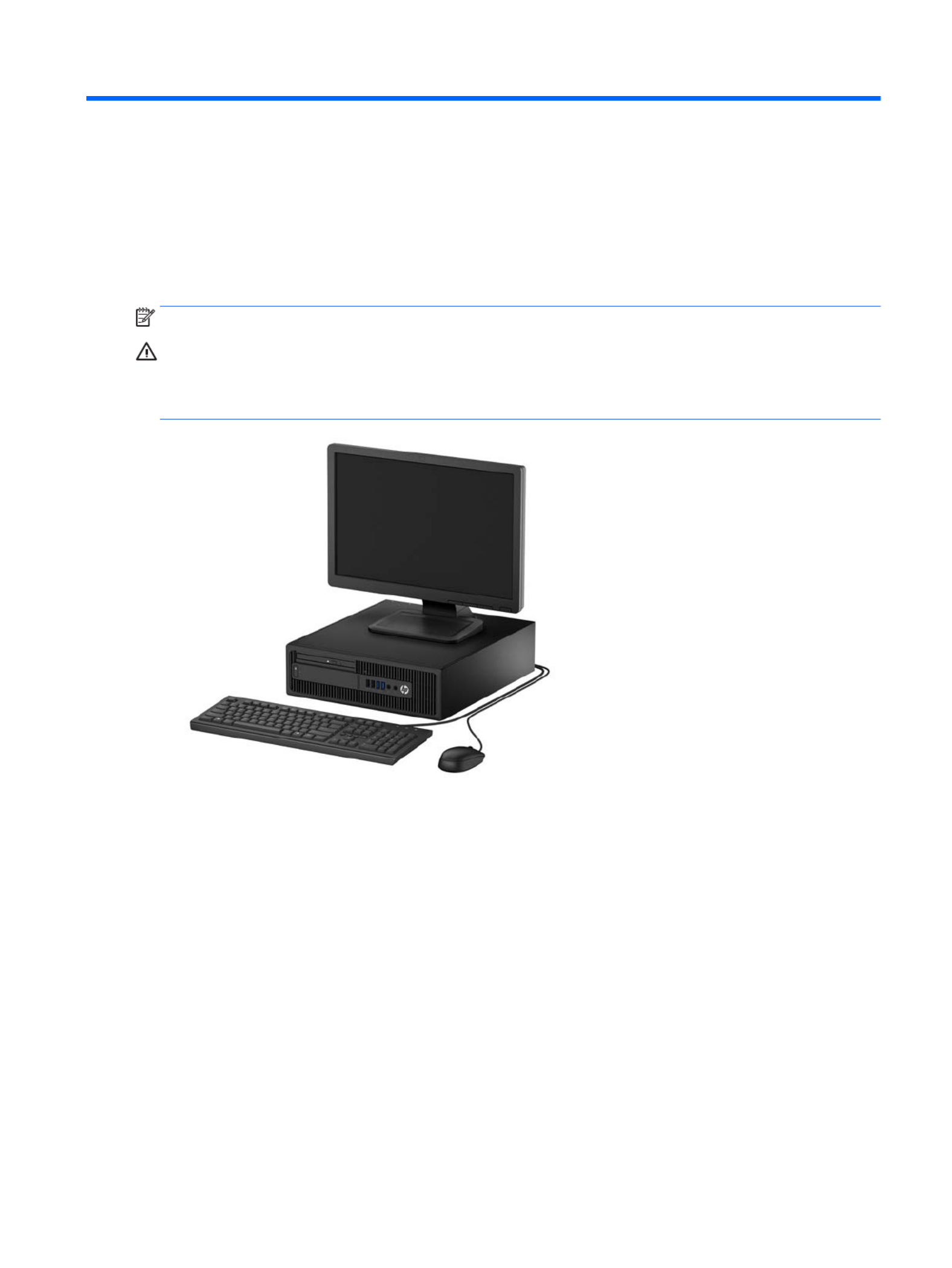
NOTE: This computer model can be used in a tower orientation or a desktop orientation.
CAUTION: Several well-known vulnerabilities exist when a computer is in the Sleep state. To prevent an
unauthorized user from accessing data on your computer, even encrypted data, HP recommends that you
always initiate Hibernation instead of Sleep anytime the computer will be out of your physical
possession. This practice is particularly important when you travel with your computer.
Standard features 1conguration

Front panel components
Drive may vary by model. Some models have a bezel blank covering the slim optical drive bay.conguration
1 Slim Optical Drive (optional) 6 Headphone Connector
2 USB 2.0 Charging (powered) Port (black) 7 Dual-State Power Button
3 USB 2.0 Port (black) 8 Hard Drive Activity Light
4 USB 3.0 Ports (blue) 9 SD Card Reader (optional)
5 Microphone/Headphone Connector
NOTE: When a device is plugged into the Microphone/Headphone Connector, a dialog box will pop up asking if you want to
use the connector for a microphone line-In device or a headphone. You can the connector at any time by recongure
double-clicking the Audio Manager icon in the Windows taskbar.
NOTE: The USB 2.0 Charging Port also provides current to charge a device such as a Smart Phone. The charging current is
available whenever the power cord is plugged into the system, even when the system is o.
NOTE: The Power On Light is normally white when the power is on. If it is red, there is a problem with the ashing
computer and it is displaying a diagnostic code. Refer to Interpreting system validation diagnostic front panel LEDs and
audible codes on page 112 to interpret the code.
2 Chapter 1 Product features

Rear panel components
1 PS/2 Mouse Connector (green) 7 PS/2 Keyboard Connector (purple)
2 Serial Connector 8 DisplayPort Monitor Connectors
3 RJ-45 Network Connector 9 VGA Monitor Connector
4 USB 2.0 Ports with Wake from S4/S5 feature
(black)
10 USB 3.0 Ports (blue)
5 Line-In Audio Connector (blue) 11 Line-Out Connector for powered audio
devices (green)
6 Power Cord Connector
NOTE: An optional second serial port and an optional parallel port are available from HP.
If using a USB keyboard, HP recommends connecting the keyboard to one of the USB 2.0 ports with the wake from S4/S5
feature. The wake from S4/S5 feature is also supported on the PS/2 connectors if enabled in BIOS F10 Setup.
When a device is plugged into the blue Line-In Audio Connector, a dialog box will pop up asking if you want to use the
connector for a line-in device or a microphone. You can the connector at any time by double-clicking the Audio recongure
Manager icon in the Windows taskbar.
When a graphics card is installed in one of the system board slots, the video connectors on the graphics card and the
integrated graphics on the system board may be used at the same time. However, for such a only the display conguration,
connected to the discrete graphics card will display POST messages.
The system board graphics can be disabled by changing settings in Computer Setup.
Rear panel components 3

Serial number location
Each computer has a unique serial number and a product ID number that are located on the exterior of the
computer. Keep these numbers available for use when contacting customer service for assistance.
4 Chapter 1 Product features
2 Illustrated parts catalog
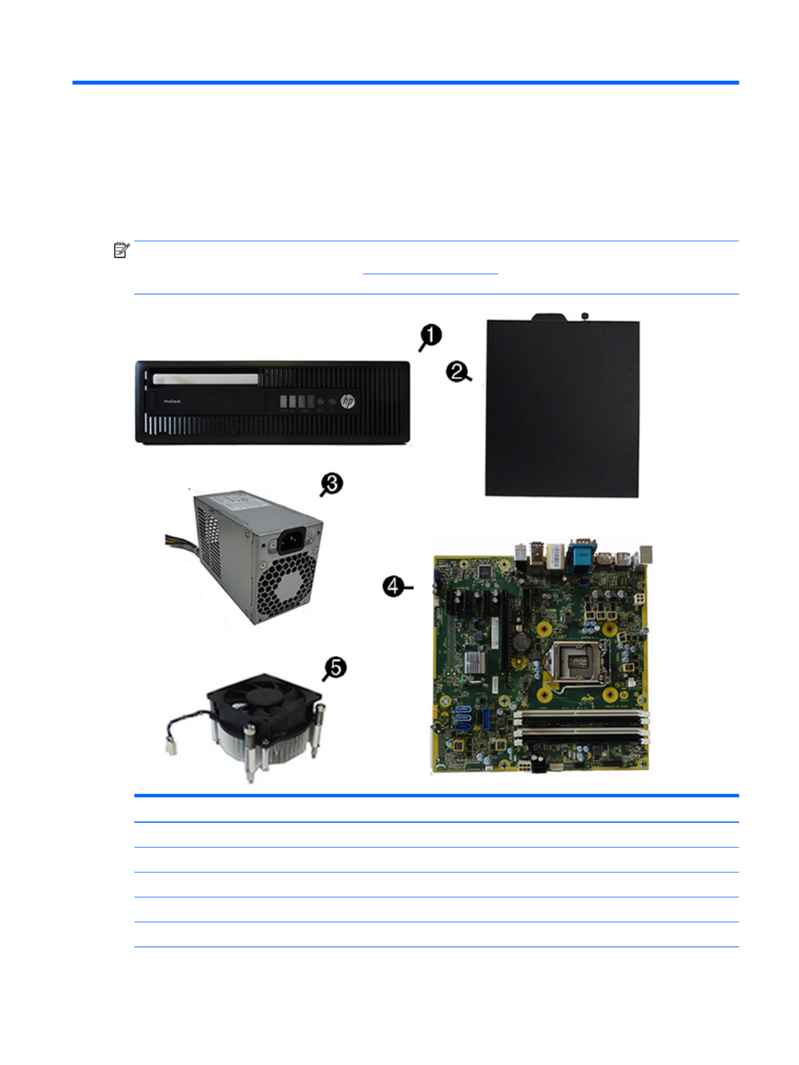
Computer major components
This chapter provides part information for all chassis.
NOTE: HP continually improves and changes product parts. For complete and current information on
supported parts for your computer, go to http://partsurfer.hp.com, select your country or region, and then
follow the on-screen instructions.
Item Description
(1) Front bezel
(2) Access panel
(3) Power supply
200W, 92% ecient
200W, 85% ecient
Computer major components 5

Item Description
200W, standard
(4) System board (includes replacement thermal material)
(5) Fan sink (includes replacement thermal material)
* (PC4-17000)Memory modules
16-GB
8-GB
4-GB
* (include replacement thermal material)Processors
Intel Core i7-6700 processor
Intel Core i5-6600 processor
Intel Core i5-6500 processor
Intel Core i3-6320 processor
Intel Core i3-6300 processor
Intel Core i3-6100 processor
Intel Pentium G4520 processor
Intel Pentium G4500 processor
Intel Pentium G4400 processor
Intel Celeron G3920 processor
Intel Celeron G3900 processor
6 Chapter 2 Illustrated parts catalog

Misc parts
Item Description
(1) Rotating fan duct
(2) Serial port, PCI card
(3) Printer port, PCI card
(4) Speaker
(5) Front I/O assembly
(6) Power switch assembly
*Fan sink duct
*SATA drive power cable
*SATA data cable, 19.5 inch, 2 straight ends
*SATA data cable, 14 inch, 1 straight end, 1 right-angle end
*M.2 USB Cable
*DisplayPort cable
Misc parts 7

Item Description
*Hard drive conversion bracket, 2.5-inch to 3.5-inch
*SATA SS power extension, 20 inch cable
*Slim optical drive bezel blank
*Hood sensor
*HP Business PC Security Lock
*Rubber foot
*Grommet, hard drive isolation, blue
*Wireless antenna for use with WLAN modules
*HP UC Speaker Phone
*HP Speaker Phone Security Sleeve
*Center strip
*Adapters
PCIe to M.2 adapter with full-sized bracket
DisplayPort to HDMI 1.4
DisplayPort to VGA
DisplayPort to DVI
DVI to VGA
DVI-I to VGA
USB-C to USB 3.0
PCIe to M.2 adapter
*Mouse
PS2, optical
USB, laser
USB, optical
Antimicrobial (People’s Republic of China only)
Washable
Wireless (Brazil only)
HP USB Hardened
*Keyboards
PS/2
PS/2 slim
USB
HP USB slim
HP USB Conferencing
8 Chapter 2 Illustrated parts catalog

Item Description
Wireless keyboard, mouse, and dongle
USB/PS2 Washable
Smart card
Drives
Description
Hard drives
2-TB, 7200-rpm
1-TB, 7200-rpm, 3.5-inch
1-TB, 7200-rpm, 2.5-inch
1-TB, hybrid SSD, 3.5-inch or 2.5-inch
500-GB, 7200-rpm, 2.5-inch, SED
500 GB, 7200 rpm, 3.5-inch or 2.5-inch
500-GB, 7200-rpm, 2.5-inch, OPAL2, self-encrypting drive (SED)
500-GB, 5400-rpm, 2.5-inch, FIPS
500-GB, hybrid SSD, 2.5-inch or 2.5-inch
500-GB, 5400-rpm, 2.5-inch, 5 mm
Solid-state drives
512 GB Solid-state Drive (SSD)
512-GB Solid-state Drive (SSD), M.2, 2280SS, PCIe
256-GB Solid-state Drive (SSD), self-encrypting (SED)
256-GB Solid-state Drive (SSD)
256-GB Solid-state Drive (SSD), TLC
256-GB Solid-state Drive (SSD), M.2, 2280SS, PCIe
256-GB Solid-state Drive (SSD), M.2, 2280SS, NVMe, PCIe
180 GB Solid-state Drive (SSD)
180 GB Solid-state Drive (SSD), OPAL2, MLC
128-GB Solid-state Drive (SSD), self-encrypting drive (SED)
128-GB Solid-state Drive (SSD)
128-GB Solid-state Drive (SSD), TLC
128-GB Solid-state Drive (SSD), M.2, 2280SS, PCIe
128-GB Solid-state Drive (SSD), M.2, 2280SS, NVMe, PCIe
120-GB Solid-state Drive (SSD)
Drives 9

Description
120-GB Solid-state Drive (SSD), OPAL2, MLC
Optical drives
Blu-ray BD-Writer XL Drive
DVD±RW drive
DVD-ROM drive
Grommet, hard drive isolation, blue
Misc boards
Description
NVIDIA GT730 2 GB DDR3 PCIex8
Intel PRO/1000 NIC
Printer port
Serial port
USB 3.1 Type Cx1 PCIe p18-x1 card
PCIe to M.2 adapter
WLAN module caddy card + Bluetooth
WLAN modules
Intel Dual Band Wireless-AC 7265 NV
Intel Dual Band Wireless-AC 8260 + Bluetooth 4.0
Intel Dual Band Wireless-AC 3165 + Bluetooth 4.0
10 Chapter 2 Illustrated parts catalog

Generating static
The following table shows that:
●Dierent activities generate amounts of static electricity.dierent
●Static electricity increases as humidity decreases.
Relative Humidity
Event 55% 40% 10%
Walking across carpet
Walking across vinyl oor
Motions of bench worker
Removing DIPs from plastic tube
7,500 V
3,000 V
400 V
400 V
15,000 V
5,000 V
800 V
700 V
35,000 V
12,000 V
6,000 V
2,000 V
Removing DIPs from vinyl tray
Removing DIPs from Styrofoam
Removing bubble pack from PCB
Packing PCBs in foam-lined box
2,000 V
3,500 V
7,000 V
5,000 V
4,000 V
5,000 V
20,000 V
11,000 V
11,500 V
14,500 V
26,500 V
21,000 V
These are then multi-packaged inside plastic tubes, trays, or Styrofoam.
NOTE: 700 volts can degrade a product.
Preventing electrostatic damage to equipment
Many electronic components are sensitive to ESD. Circuitry design and structure determine the degree of
sensitivity. The following packaging and grounding precautions are necessary to prevent damage to electric
components and accessories.
●To avoid hand contact, transport products in static-safe containers such as tubes, bags, or boxes.
●Protect all electrostatic parts and assemblies with conductive or approved containers or packaging.
●Keep electrostatic sensitive parts in their containers until they arrive at static-free stations.
●Place items on a grounded surface before removing them from their container.
●Always be properly grounded when touching a sensitive component or assembly.
●Avoid contact with pins, leads, or circuitry.
●Place reusable electrostatic-sensitive parts from assemblies in protective packaging or conductive
foam.
Personal grounding methods and equipment
Use the following equipment to prevent static electricity damage to equipment:
●Wrist straps are straps with a maximum of one-megohm ± 10% resistance in the ground cords. exible
To provide proper ground, a strap must be worn snug against bare skin. The ground cord must be
connected and snugly into the banana plug connector on the grounding mat or workstation.t
12 Chapter 3 Routine care, SATA drive guidelines, and disassembly preparation

●Heel straps/Toe straps/Boot straps can be used at standing workstations and are compatible with
most types of shoes or boots. On conductive or dissipative mats, use them on both feet with oors oor
a maximum of one-megohm ± 10% resistance between the operator and ground.
Static Shielding Protection Levels
Method Voltage
Antistatic plastic
Carbon-loaded plastic
Metallized laminate
1,500
7,500
15,000
Grounding the work area
To prevent static damage at the work area, use the following precautions:
●Cover the work surface with approved static-dissipative material. Provide a wrist strap connected to the
work surface and properly grounded tools and equipment.
●Use static-dissipative mats, foot straps, or air ionizers to give added protection.
●Handle electrostatic sensitive components, parts, and assemblies by the case or PCB laminate. Handle
them only at static-free work areas.
●Turn power and input signals before inserting and removing connectors or test equipment.o
●Use made of static-safe materials when must directly contact dissipative surfaces.xtures xtures
●Keep work area free of nonconductive materials such as ordinary plastic assembly aids and Styrofoam.
●Use service tools, such as cutters, screwdrivers, and vacuums, that are conductive.eld
Recommended materials and equipment
Materials and equipment that are recommended for use in preventing static electricity include:
●Antistatic tape
●Antistatic smocks, aprons, or sleeve protectors
●Conductive bins and other assembly or soldering aids
●Conductive foam
●Conductive tabletop workstations with ground cord of one-megohm +/- 10% resistance
●Static-dissipative table or mats with hard tie to groundoor
●Field service kits
●Static awareness labels
●Wrist straps and footwear straps providing one-megohm +/- 10% resistance
●Material handling packages
●Conductive plastic bags
●Conductive plastic tubes
●Conductive tote boxes
●Opaque shielding bags
Electrostatic discharge information 13

●Transparent metallized shielding bags
●Transparent shielding tubes
Operating guidelines
To prevent overheating and to help prolong the life of the computer:
●Keep the computer away from excessive moisture, direct sunlight, and extremes of heat and cold.
●Operate the computer on a sturdy, level surface. Leave a 10.2-cm (4-inch) clearance on all vented sides
of the computer and above the monitor to permit the required airow.
●Never restrict the into the computer by blocking any vents or air intakes. Do not place the airow
keyboard, with the keyboard feet down, directly against the front of the desktop unit as this also
restricts airow.
●Occasionally clean the air vents on all vented sides of the computer. Lint, dust, and other foreign matter
can block the vents and limit the Be sure to unplug the computer before cleaning the air vents.airow.
●Never operate the computer with the cover or side panel removed.
●Do not stack computers on top of each other or place computers so near each other that they are subject
to each other’s re-circulated or preheated air.
●If the computer is to be operated within a separate enclosure, intake and exhaust ventilation must be
provided on the enclosure, and the same operating guidelines listed above will still apply.
●Keep liquids away from the computer and keyboard.
●Never cover the ventilation slots on the monitor with any type of material.
●Install or enable power management functions of the operating system or other software, including
sleep states.
Routine care
General cleaning safety precautions
1. Never use solvents or solutions to clean the computer.ammable
2. Never immerse any parts in water or cleaning solutions; apply any liquids to a clean cloth and then use
the cloth on the component.
3. Always unplug the computer when cleaning with liquids or damp cloths.
4. Always unplug the computer before cleaning the keyboard, mouse, or air vents.
5. Disconnect the keyboard before cleaning it.
6. Wear safety glasses equipped with side shields when cleaning the keyboard.
Cleaning the Computer Case
Follow all safety precautions in General cleaning safety precautions on page 14 before cleaning the computer.
14 Chapter 3 Routine care, SATA drive guidelines, and disassembly preparation

To clean the computer case, follow the procedures described below:
●To remove light stains or dirt, use plain water with a clean, lint-free cloth or swab.
●For stronger stains, use a mild dishwashing liquid diluted with water. Rinse well by wiping it with a cloth
or swab dampened with clear water.
●For stubborn stains, use isopropyl (rubbing) alcohol. No rinsing is needed as the alcohol will evaporate
quickly and not leave a residue.
●After cleaning, always wipe the unit with a clean, lint-free cloth.
●Occasionally clean the air vents on the computer. Lint and other foreign matter can block the vents and
limit the airow.
Cleaning the keyboard
Follow all safety precautions in General cleaning safety precautions on page 14 before cleaning the keyboard.
To clean the tops of the keys or the keyboard body, follow the procedures described in Cleaning the Computer
Case on page 14.
When cleaning debris from under the keys, review all rules in General cleaning safety precautions on page 14
before following these procedures:
CAUTION: Use safety glasses equipped with side shields before attempting to clean debris from under the
keys.
●Visible debris underneath or between the keys may be removed by vacuuming or shaking.
●Canned, pressurized air may be used to clean debris from under the keys. Caution should be used as too
much air pressure can dislodge lubricants applied under the wide keys.
●If you remove a key, use a specially designed key puller to prevent damage to the keys. This tool is
available through many electronic supply outlets.
CAUTION: Never remove a wide leveled key (like the space bar) from the keyboard. If these keys are
improperly removed or installed, the keyboard may not function properly.
●Cleaning under a key may be done with a swab moistened with isopropyl alcohol and squeezed out. Be
careful not to wipe away lubricants necessary for proper key functions. Use tweezers to remove any
bers conned or dirt in areas. Allow the parts to air dry before reassembly.
Cleaning the monitor
●Wipe the monitor screen with a clean cloth moistened with water or with a towelette designed for
cleaning monitors. Do not use sprays or aerosols directly on the screen; the liquid may seep into the
housing and damage a component. Never use solvents or liquids on the monitor.ammable
●To clean the monitor body follow the procedures in Cleaning the Computer Case on page 14.
Cleaning the mouse
Before cleaning the mouse, ensure that the power to the computer is turned o.
●Clean the mouse ball by removing the retaining plate and the ball from the housing. Pull out any rst
debris from the ball socket and wipe the ball with a clean, dry cloth before reassembly.
●To clean the mouse body, follow the procedures in Cleaning the Computer Case on page 14.
Routine care 15

Service considerations
Listed below are some of the considerations that you should keep in mind during the disassembly and
assembly of the computer.
Power supply fan
The power supply fan is a variable-speed fan based on the temperature in the power supply.
CAUTION: The cooling fan is always on when the computer is in the “On” mode. The cooling fan is when o
the computer is in “Standby,” “Suspend,” or modes. “O”
You must disconnect the power cord from the power source before opening the computer to prevent system
board or component damage.
Tools and software Requirements
To service the computer, you need the following:
●Torx T-15 screwdriver
●Torx T-15 screwdriver with small diameter shank (for certain front bezel removal)
●Flat-bladed screwdriver (may sometimes be used in place of the Torx screwdriver)
●Phillips #2 screwdriver
●Diagnostics software
●Tamper-resistant T-15 wrench
Screws
The screws used in the computer are not interchangeable. They may have standard or metric threads and may
be of lengths. If an incorrect screw is used during the reassembly process, it can damage the unit. HP dierent
strongly recommends that all screws removed during disassembly be kept with the part that was removed,
then returned to their proper locations.
CAUTION: Metric screws have a black U.S. screws have a silver and are used on hard drives only.nish. nish
CAUTION: As each subassembly is removed from the computer, it should be placed away from the work area
to prevent damage.
Cables and connectors
Most cables used throughout the unit are cables. These cables must be handled with care to at, exible
avoid damage. Apply only the tension required to seat or unseat the cables during insertion or removal from
the connector. Handle cables by the connector whenever possible. In all cases, avoid bending or twisting the
cables, and ensure that the cables are routed in such a way that they cannot be caught or snagged by parts
being removed or replaced.
CAUTION: When servicing this computer, ensure that cables are placed in their proper location during the
reassembly process. Improper cable placement can damage the computer.
Hard Drives
Handle hard drives as delicate, precision components, avoiding all physical shock and vibration. This applies
to failed drives as well as replacement spares.
16 Chapter 3 Routine care, SATA drive guidelines, and disassembly preparation

●If a drive must be mailed, place the drive in a bubble-pack mailer or other suitable protective packaging
and label the package “Fragile: Handle With Care.”
●Do not remove hard drives from the shipping package for storage. Keep hard drives in their protective
packaging until they are actually mounted in the CPU.
●Avoid dropping drives from any height onto any surface.
●If you are inserting or removing a hard drive, turn the computer. Do not remove a hard drive while the o
computer is on or in standby mode.
●Before handling a drive, ensure that you are discharged of static electricity. While handling a drive, avoid
touching the connector.
●Do not use excessive force when inserting a drive.
●Avoid exposing a hard drive to liquids, temperature extremes, or products that have magnetic elds
such as monitors or speakers.
Lithium coin cell battery
The battery that comes with the computer provides power to the real-time clock and has a minimum lifetime
of about three years.
See the appropriate removal and replacement chapter for the chassis you are working on in this guide for
instructions on the replacement procedures.
WARNING! This computer contains a lithium battery. There is a risk of and chemical burn if the battery is re
handled improperly. Do not disassemble, crush, puncture, short external contacts, dispose in water or or re,
expose it to temperatures higher than 140ºF (60ºC). Do not attempt to recharge the battery.
NOTE: Batteries, battery packs, and accumulators should not be disposed of together with the general
household waste. In order to forward them to recycling or proper disposal, please use the public collection
system or return them to HP, their authorized partners, or their agents.
SATA hard drives
Serial ATA Hard Drive Characteristics
Number of pins/conductors in data cable 7/7
Number of pins in power cable 15
Maximum data cable length 39.37 in (100 cm)
Data interface voltage 400-700 mVdierential
Drive voltages 3.3 V, 5 V, 12 V
Jumpers for drive N/Aconguring
Data transfer rate 6.0 Gb/s
SATA hard drives 17

SATA hard drive cables
SATA data cable
Always use an HP approved SATA 6.0 Gb/s cable as it is fully backwards compatible with the SATA 1.5 Gb/s
drives.
Current HP desktop products ship with SATA 6.0 Gb/s hard drives.
SATA data cables are susceptible to damage if Never crease a SATA data cable and never bend it overexed.
tighter than a 30 mm (1.18 in) radius.
The SATA data cable is a thin, 7-pin cable designed to transmit data for only a single drive.
SMART ATA drives
The Self Monitoring Analysis and Recording Technology (SMART) ATA drives for the HP Personal Computers
have built-in drive failure prediction that warns the user or network administrator of an impending failure or
crash of the hard drive. The SMART drive tracks fault prediction and failure indication parameters such as
reallocated sector count, spin retry count, and calibration retry count. If the drive determines that a failure is
imminent, it generates a fault alert.
Cable management
Always follow good cable management practices when working inside the computer.
●Keep cables away from major heat sources like the heat sink.
●Do not jam cables on top of expansion cards or memory modules. Printed circuit cards like these are not
designed to take excessive pressure on them.
●Keep cables clear of sliding or moveable parts to prevent them from being cut or crimped when the parts
are moved.
●When folding a ribbon cable, never fold to a sharp crease. Sharp creases may damage the wires.at
●Some ribbon cables come prefolded. Never change the folds on these cables.at
●Do not bend any cable sharply. A sharp bend can break the internal wires.
●Never bend a SATA data cable tighter than a 30 mm (1.18 in) radius.
●Never crease a SATA data cable.
●Do not rely on components like the drive cage, power supply, or computer cover to push cables down
into the chassis. Always position the cables to lay properly by themselves.
18 Chapter 3 Routine care, SATA drive guidelines, and disassembly preparation

4 Removal and replacement procedures:
Small Form Factor
Adherence to the procedures and precautions described in this chapter is essential for proper service. After
completing all necessary removal and replacement procedures, run the Diagnostics utility to verify that all
components operate properly.
NOTE: Not all features listed in this guide are available on all computers.
Preparation for disassembly
See Routine care, SATA drive guidelines, and disassembly preparation on page 11 for initial safety procedures.
1. Remove/disengage any security devices that prohibit opening the computer.
2. Remove all removable media, such as compact discs or USB drives, from the computer.ash
3. Turn the computer properly through the operating system, then turn any external devices.o o
4. Disconnect the power cord from the power outlet and disconnect any external devices.
CAUTION: Turn the computer before disconnecting any cables.o
Regardless of the power-on state, voltage is always present on the system board as long as the system
is plugged into an active AC outlet. In some systems the cooling fan is on even when the computer is in
the “Standby,” or “Suspend” modes. The power cord should always be disconnected before servicing a
unit.
5. If the computer is on a stand, remove the computer from the stand and lay the computer down.
NOTE: During disassembly, label each cable as you remove it, noting its position and routing. Keep all
screws with the units removed.
Preparation for disassembly 19
Access panel
1. Prepare the computer for disassembly (Preparation for disassembly on page 19).
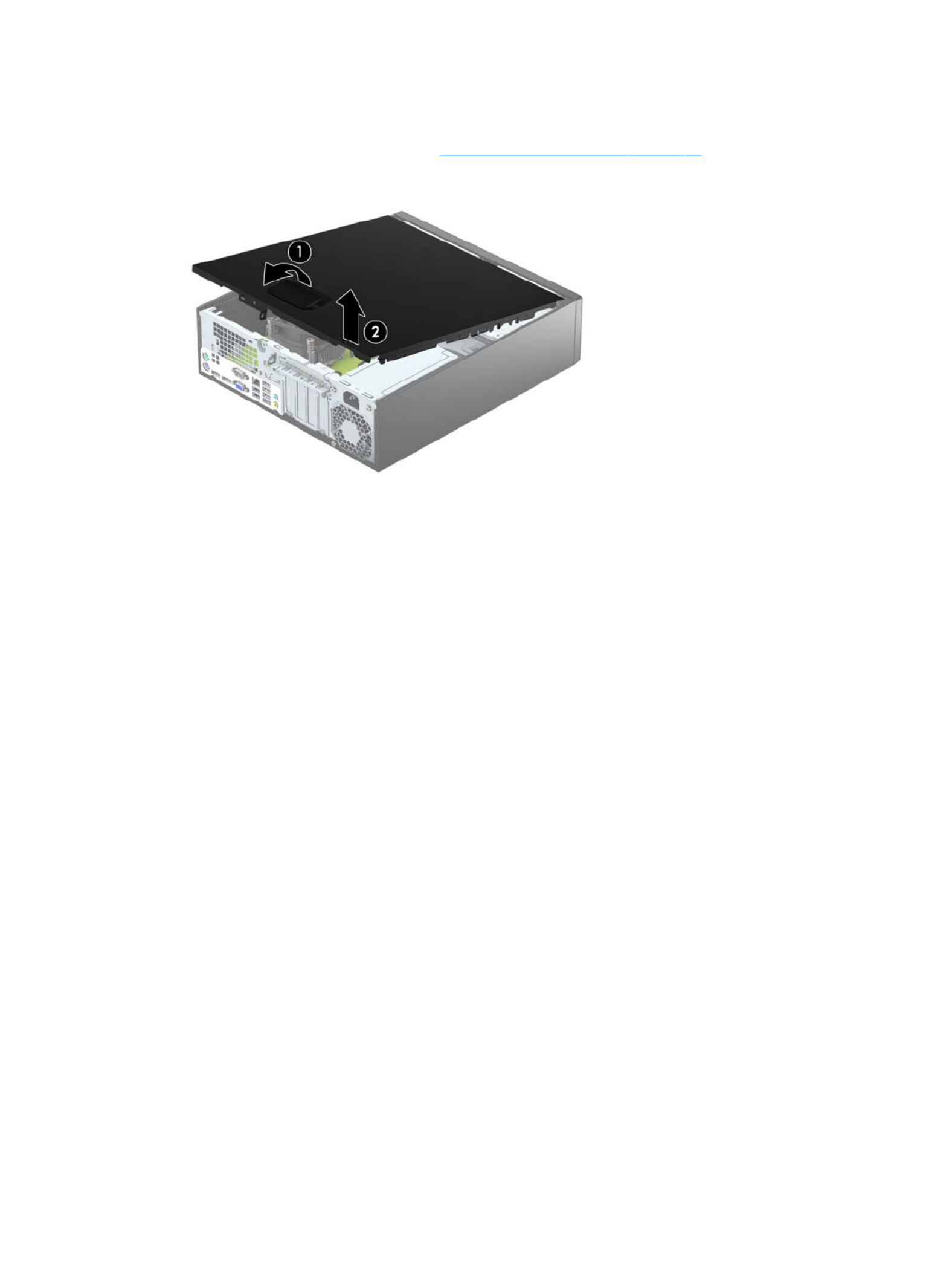
2. Pull up the access panel handle , and then lift the panel the computer .(1) o (2)
To install the access panel, reverse the removal procedure.
20 Chapter 4 Removal and replacement procedures: Small Form Factor

Front bezel
1. Prepare the computer for disassembly (Preparation for disassembly on page 19).
2. Remove the access panel (Access panel on page 20).
3. Lift up the three tabs on the side of the bezel , and then rotate the bezel the chassis .(1) o (2)
To install the front bezel, reverse the removal procedure.
Front bezel 21

Front bezel security
The front bezel can be locked in place by installing a security screw provided by HP. To install the security
screw:
1. Prepare the computer for disassembly (Preparation for disassembly on page 19).
2. Remove the access panel (Access panel on page 20).
3. If you do not have a 6-32 standard screw, remove one of the four silver 6-32 standard screws located on
top of the drive cage. Refer to Drives on page 33 for an illustration of the 6-32 standard screw
locations.
4. Install the 6-32 security screw through the middle front bezel release tab to secure the front bezel in
place.
22 Chapter 4 Removal and replacement procedures: Small Form Factor

Bezel blanks
On some models, there are bezel blanks covering the 3.5-inch and 5.25-inch external drive bays that need to
be removed before installing a drive. To remove a bezel blank:
1. Remove the access panel (Access panel on page 20).
2. Remove the front bezel (Front bezel on page 21).
3. To remove the slim optical drive bezel blank, press inward on the three retaining tabs that hold the bezel
blank in place (1), and then rotate the bezel blank the front bezel .o (2)
NOTE: After removing the slim optical drive bezel blank and installing a slim optical drive, you can install an
optional bezel trim piece (available from HP) that surrounds the front of the slim optical drive.
Bezel blanks 23

Memory
Description
16-GB, PC4-17000
8-GB, PC4-17000
4-GB, PC4-17000
The computer comes with double data rate 4 synchronous dynamic random access memory (DDR4-SDRAM)
dual inline memory modules (DIMMs).
DIMMs
The memory sockets on the system board can be populated with up to four industry-standard DIMMs. These
memory sockets are populated with at least one preinstalled DIMM. To achieve the maximum memory
support, you can populate the system board with up to 64-GB of memory in a high-performing congured
dual channel mode.
DDR4-SDRAM DIMMs
For proper system operation, the DIMMs must be:
●industry-standard 288-pin
●unbuered non-ECC PC4-17000 DDR4-2133 MHz-compliant
●1.2 volt DDR4-SDRAM DIMMs
The DIMMs must also:
●support CAS latency 15 DDR4 2133 MHz (15-15-15 timing)
●contain the mandatory JEDEC SPD information
In addition, the computer supports:
●512-Mbit, 1-Gbit, and 2-Gbit non-ECC memory technologies
●single-sided and double-sided DIMMs
●DIMMs constructed with x8 and x16 DDR devices; DIMMs constructed with p32-x4 SDRAM are not supported
NOTE: The system will not operate properly if you install unsupported DIMMs.
24 Chapter 4 Removal and replacement procedures: Small Form Factor

Populating DIMM sockets
There are four DIMM sockets on the system board, with two sockets per channel. The sockets are labeled
DIMM1, DIMM2, DIMM3, and DIMM4. Sockets DIMM1 and DIMM2 operate in memory channel B. Sockets DIMM3
and DIMM4 operate in memory channel A.
The system will automatically operate in single channel mode, dual channel mode, or mode, depending ex
on how the DIMMs are installed.
NOTE: Single channel and unbalanced dual channel memory will result in inferior graphics congurations
performance.
●The system will operate in single channel mode if the DIMM sockets are populated in one channel only.
●The system will operate in a higher-performing dual channel mode if the total memory capacity of the
DIMMs in Channel A is equal to the total memory capacity of the DIMMs in Channel B. The technology and
device width can vary between the channels. For example, if Channel A is populated with two 1-GB
DIMMs and Channel B is populated with one 2-GB DIMM, the system will operate in dual channel mode.
●The system will operate in mode if the total memory capacity of the DIMMs in Channel A is not equal ex
to the total memory capacity of the DIMMs in Channel B. In mode, the channel populated with the ex
least amount of memory describes the total amount of memory assigned to dual channel and the
remainder is assigned to single channel. For optimal speed, the channels should be balanced so that the
largest amount of memory is spread between the two channels. If one channel will have more memory
than the other, the larger amount should be assigned to Channel A. For example, if you are populating
the sockets with one 2-GB DIMM, and three 1-GB DIMMs, Channel A should be populated with the 2-GB
DIMM and one 1-GB DIMM, and Channel B should be populated with the other two 1-GB DIMMs. With this
conguration, 4-GB will run as dual channel and 1-GB will run as single channel.
●In any mode, the maximum operational speed is determined by the slowest DIMM in the system.
Installing DIMMs
CAUTION: You must disconnect the power cord and wait approximately 30 seconds for the power to drain
before adding or removing memory modules. Regardless of the power-on state, voltage is always supplied to
the memory modules as long as the computer is plugged into an active AC outlet. Adding or removing
memory modules while voltage is present may cause irreparable damage to the memory modules or system
board.
The memory module sockets have gold-plated metal contacts. When upgrading the memory, it is important
to use memory modules with gold-plated metal contacts to prevent corrosion and/or oxidation resulting from
having incompatible metals in contact with each other.
Static electricity can damage the electronic components of the computer or optional cards. Before beginning
these procedures, ensure that you are discharged of static electricity by briey touching a grounded metal
object.
When handling a memory module, be careful not to touch any of the contacts. Doing so may damage the
module.
1. Prepare the computer for disassembly (Preparation for disassembly on page 19).
2. Remove the access panel (Access panel on page 20).
3. Rotate up the internal drive bay housing to access the memory module sockets on the system board.
Memory 25
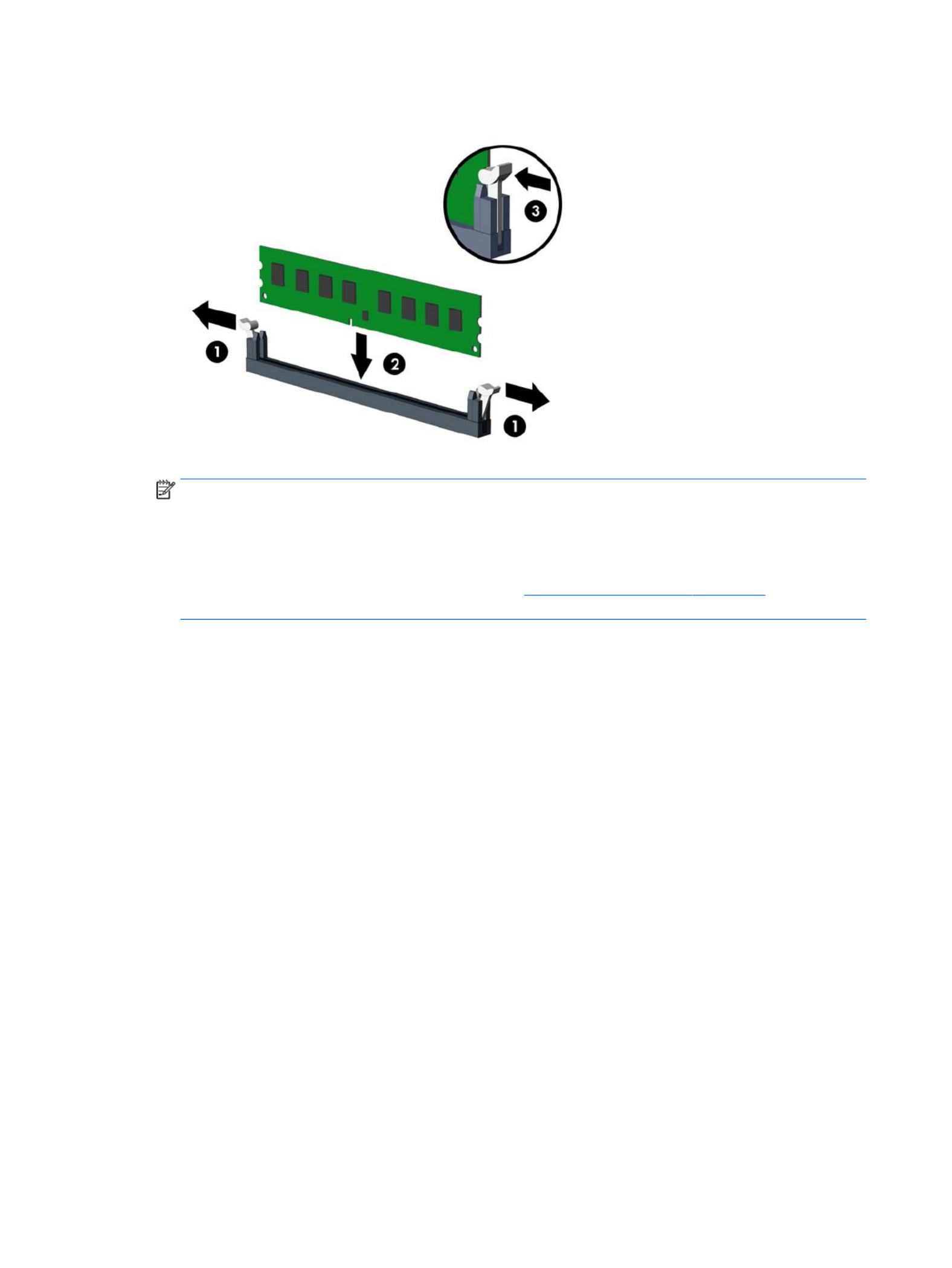
4. Open both latches of the memory module socket , and insert the memory module into the socket .(1) (2)
NOTE: A memory module can be installed in only one way. Match the notch on the module with the tab
on the memory socket.
Populate the black DIMM sockets before the white DIMM sockets.
For maximum performance, populate the sockets so that the memory capacity is spread as equally as
possible between Channel A and Channel B. Refer to Populating DIMM sockets on page 25 for more
information.
5. Push the module down into the socket, ensuring that the module is fully inserted and properly seated.
Make sure the latches are in the closed position .(3)
6. Repeat steps 4 and 5 to install any additional modules.
The computer should automatically recognize the additional memory the next time you turn on the computer.
26 Chapter 4 Removal and replacement procedures: Small Form Factor

Expansion card
Description
NVIDIA GT730 2 GB DDR3 PCIex8
Intel PRO/1000 NIC
Printer port
Serial port
USB 3.1 Type Cx1 PCIe p35-x1 card
PCIe to M.2 adapter
WLAN module caddy card + Bluetooth
Intel Dual Band Wireless-AC 7265 NV
Intel Dual Band Wireless-AC 8260 + Bluetooth 4.0
Intel Dual Band Wireless-AC 3165 + Bluetooth 4.0
The computer has three PCI Express p35-x1 expansion sockets and one PCI Express x16 expansion socket.
NOTE: The PCI Express sockets support only low cards.prole
You can install a PCI Express x1, x4, x8, or x16 expansion card in the PCI Express x16 socket.
For dual graphics card the (primary) card must be installed in the PCI Express x16 socket.congurations, rst
To remove, replace, or add an expansion card:
1. Prepare the computer for disassembly (Preparation for disassembly on page 19).
2. Remove the access panel (Access panel on page 20).
3. Locate the correct vacant expansion socket on the system board and the corresponding expansion slot
on the back of the computer chassis.
4. Release the slot cover retention latch that secures the slot covers by lifting the tab on the latch and
rotating the latch to the open position.
Expansion card 27
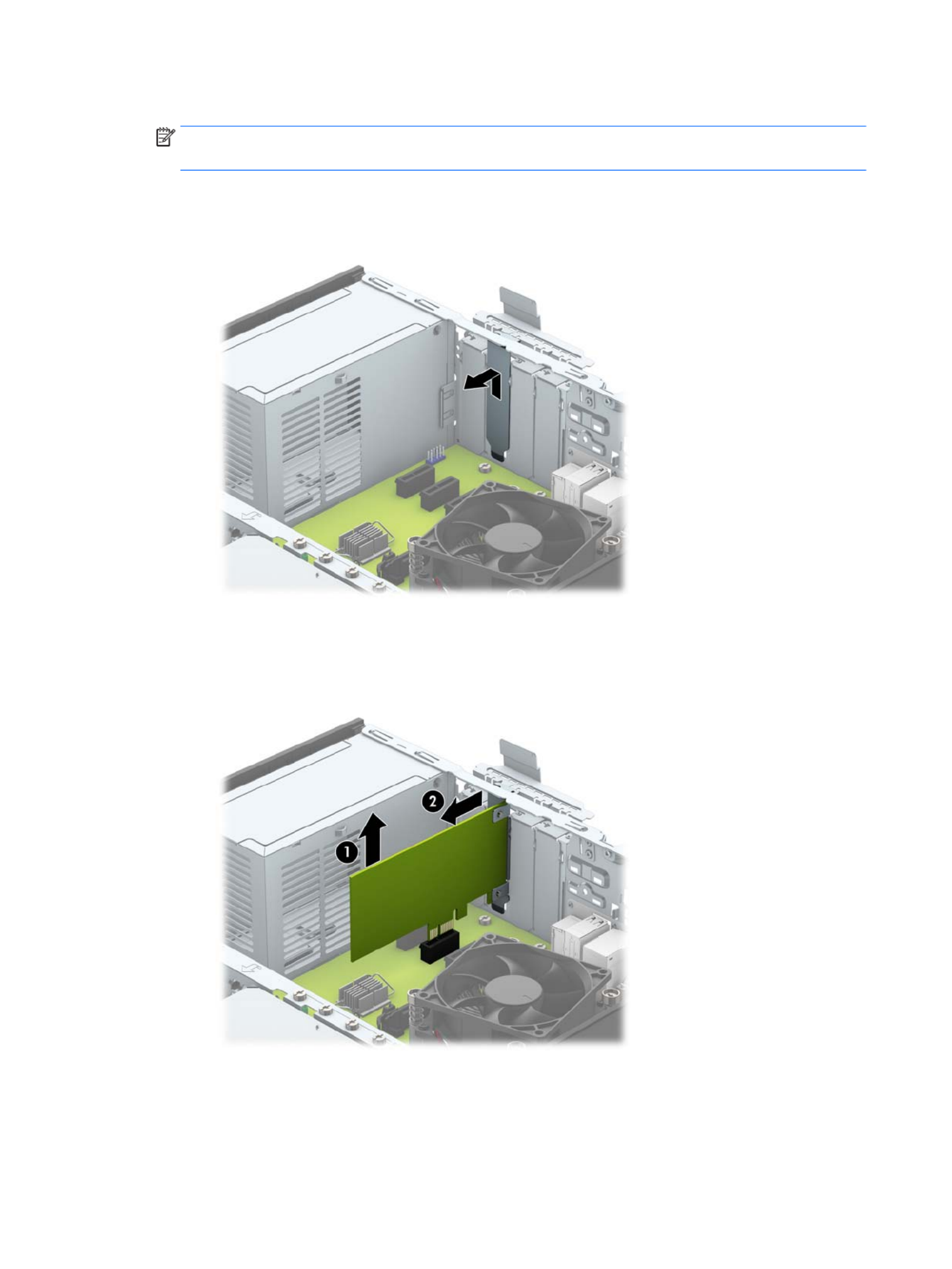
5. Before installing an expansion card, remove the expansion slot cover or the existing expansion card.
NOTE: Before removing an installed expansion card, disconnect any cables that may be attached to
the expansion card.
a. If you are installing an expansion card in a vacant socket, remove the appropriate expansion slot
cover on the back of the chassis. Pull the slot cover straight up then away from the inside of the
chassis.
b. If you are removing a PCI Express p36-x1 card, hold the card at each end, and carefully rock it back and
forth until the connectors pull free from the socket. Pull the expansion card straight up from the
socket (1) then away from the inside of the chassis to release it from the chassis frame (2). Be sure
not to scrape the card against the other components.
28 Chapter 4 Removal and replacement procedures: Small Form Factor

c. If you are removing a PCI Express x16 card, pull the retention arm on the back of the expansion
socket away from the card and carefully rock the card back and forth until the connectors pull free
from the socket. Pull the expansion card straight up from the socket then away from the inside of
the chassis to release it from the chassis frame. Be sure not to scrape the card against the other
components.
6. Store the removed card in anti-static packaging.
7. If you are not installing a new expansion card, install an expansion slot cover to close the open slot.
CAUTION: After removing an expansion card, you must replace it with a new card or expansion slot
cover for proper cooling of internal components during operation.
Expansion card 29

8. To install a new expansion card, hold the card just above the expansion socket on the system board then
move the card toward the rear of the chassis (1) so that the bracket on the card is aligned with the open
slot on the rear of the chassis. Press the card straight down into the expansion socket on the system
board (2).
NOTE: When installing an expansion card, press on the card so that the whole connector seats rmly
properly in the expansion card socket.
9. Rotate the slot cover retention latch back in place to secure the expansion card.
10. Connect external cables to the installed card, if needed. Connect internal cables to the system board, if
needed.
11. Recongure the computer, if necessary.
30 Chapter 4 Removal and replacement procedures: Small Form Factor

System board connections
Refer to the following illustration and table to identify the system board connectors for your model.
No. System Board Connector System Board Label Color Component
1 PCI Express x1 X1PCIEXP3 black Expansion Card
2 PCI Express x1 X1PCIEXP2 black Expansion Card
3 PCI Express x1 X1PCIEXP1 black Expansion Card
4 PCI Express x16 X16PCIEXP black Expansion Card
5 Battery BAT black Battery
6 Serial Port COMB black Optional Second Serial Port
7 DIMM4 (Channel A) DIMM4 white Memory Module
8 DIMM3 (Channel A) DIMM3 black Memory Module
9 DIMM2 (Channel B) DIMM2 white Memory Module
10 DIMM1 (Channel B) DIMM1 black Memory Module
11 SATA 3.0 SATA2 light blue Any SATA Device other than the Primary
Hard Drive
12 SATA 3.0 SATA1 light blue Any SATA Device other than the Primary
Hard Drive
13 SATA 3.0 SATA0 dark blue Primary Hard Drive
System board connections 31

Rotating the drive cage
You must rotate the drive cage to the upright position to access most computer components.
1. Prepare the computer for disassembly (Preparation for disassembly on page 19).
2. To access internal components: Rotate the drive cage upward until it is fully open.
3. To reassemble the computer: Rotate the drive cage back down to its normal position.
CAUTION: Be careful not to pinch any cables or wires when rotating the drive cage down.
32 Chapter 4 Removal and replacement procedures: Small Form Factor

Drives
Description
Hard drives
2-TB, 7200-rpm
1-TB, 7200-rpm, 3.5-inch
1-TB, 7200-rpm, 2.5-inch
1-TB, hybrid SSD, 3.5-inch or 2.5-inch
500-GB, 7200-rpm, 2.5-inch, SED
500 GB, 7200 rpm, 3.5-inch or 2.5-inch
500-GB, 7200-rpm, 2.5-inch, OPAL2, self-encrypting drive (SED)
500-GB, 5400-rpm, 2.5-inch, FIPS
500-GB, hybrid SSD, 2.5-inch or 2.5-inch
500-GB, 5400-rpm, 2.5-inch, 5 mm
Solid-state drives
512 GB Solid-state Drive (SSD)
512-GB Solid-state Drive (SSD), M.2, 2280SS, PCIe
256-GB Solid-state Drive (SSD), self-encrypting (SED)
256-GB Solid-state Drive (SSD)
256-GB Solid-state Drive (SSD), TLC
256-GB Solid-state Drive (SSD), M.2, 2280SS, PCIe
256-GB Solid-state Drive (SSD), M.2, 2280SS, NVMe, PCIe
180 GB Solid-state Drive (SSD)
180 GB Solid-state Drive (SSD), OPAL2, MLC
128-GB Solid-state Drive (SSD), self-encrypting drive (SED)
128-GB Solid-state Drive (SSD)
128-GB Solid-state Drive (SSD), TLC
128-GB Solid-state Drive (SSD), M.2, 2280SS, PCIe
128-GB Solid-state Drive (SSD), M.2, 2280SS, NVMe, PCIe
120-GB Solid-state Drive (SSD)
120-GB Solid-state Drive (SSD), OPAL2, MLC
Optical drives
Blu-ray BD-Writer XL Drive
DVD±RW drive
Drives 33

Description
DVD-ROM drive
Grommet, hard drive isolation, blue
When installing drives, follow these guidelines:
●The primary Serial ATA (SATA) hard drive must be connected to the dark blue primary SATA connector on
the system board labeled SATA0.
●Connect secondary hard drives and optical drives to one of the light blue SATA connectors on the system
board (labeled SATA1 and SATA2).
●HP has provided extra 6-32 hard drive mounting screws installed on the top of the hard drive cage (1)
for installing a hard drive into the 3.5-inch secondary hard drive bay. If you are replacing a hard drive,
remove the mounting screws from the old drive and install them in the new drive.
NOTE: You can also use one of the extra mounting screws to secure the front bezel (see Front bezel
security on page 22 for more information).
CAUTION: To prevent loss of work and damage to the computer or drive:
If you are inserting or removing a drive, shut down the operating system properly, turn the computer, and o
unplug the power cord. Do not remove a drive while the computer is on or in standby mode.
Before handling a drive, ensure that you are discharged of static electricity. While handling a drive, avoid
touching the connector. For more information about preventing electrostatic damage, refer to Electrostatic
discharge information on page 11.
Handle a drive carefully; do not drop it.
Do not use excessive force when inserting a drive.
Avoid exposing a hard drive to liquids, temperature extremes, or products that have magnetic such as elds
monitors or speakers.
If a drive must be mailed, place the drive in a bubble-pack mailer or other protective packaging and label the
package “Fragile: Handle With Care.”
34 Chapter 4 Removal and replacement procedures: Small Form Factor

Drive positions
1 9.5mm slim optical drive bay
2 3.5-inch primary hard drive bay
3 3.5-inch secondary hard drive bay
4 2.5-inch hard drive bay
NOTE: The drive on your computer may be than the drive conguration dierent
conguration shown above.
To verify the type and size of the storage devices installed in the computer, run Computer Setup.
Drives 35

Removing a 9.5mm slim optical drive
CAUTION: All removable media should be taken out of a drive before removing the drive from the computer.
1. Prepare the computer for disassembly (Preparation for disassembly on page 19).
2. Remove the access panel (Access panel on page 20).
3. Disconnect the power cable and data cable from the rear of the optical drive, push the green (1) (2)
release latch on the right rear side of the drive toward the center of the drive , and then slide the drive (3)
forward and out of the bay through the front bezel .(4)
CAUTION: When removing the cables, pull the tab or connector instead of the cable itself to avoid
damaging the cable.
36 Chapter 4 Removal and replacement procedures: Small Form Factor
Installing a 9.5mm slim optical drive
1. Prepare the computer for disassembly (Preparation for disassembly on page 19).
2. Remove the access panel (Access panel on page 20).
3. Remove the front bezel if you are installing a drive in a bay covered by a bezel blank, then remove the
bezel blank. See Bezel blanks on page 23 for more information.
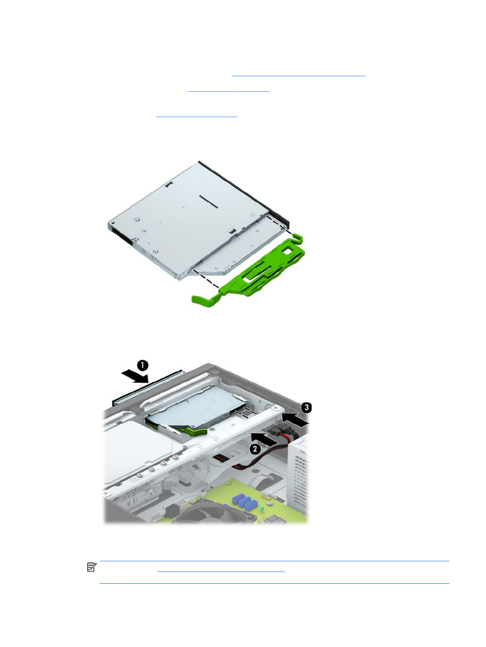
4. Align the small pin on the release latch with the small hole on the side of the drive and press the latch
rmly onto the drive.
5. Slide the optical drive through the front of the chassis all the way into the bay so that it locks in place
(1), and then connect the power cable and data cable to the rear of the drive.(2) (3)
6. Connect the opposite end of the data cable to one of the light blue SATA connectors on the system
board.
NOTE: Refer to System board connections on page 31 for an illustration of the system board drive
connectors.
Drives 37

Removing and replacing a primary 3.5-inch hard drive
CAUTION: All removable media should be taken out of a drive before removing the drive from the computer.
1. Prepare the computer for disassembly (Preparation for disassembly on page 19).
2. Remove the access panel (Access panel on page 20).
3. Rotate the drive cage to its upright position (Rotating the drive cage on page 32).
4. Disconnect the power cable and data cable from the back of the hard drive.(1) (2)
5. Pull the release lever next to the rear of the hard drive outward . While pulling the release lever out, (1)
slide the drive back until it stops, and then lift the drive up and out of the bay .(2)
38 Chapter 4 Removal and replacement procedures: Small Form Factor

6. To install a hard drive, you must transfer the mounting screws from the old hard drive to the new hard
drive.
7. Align the mounting screws with the slots on the chassis drive cage, press the hard drive down into the
bay, and then slide it forward until it stops and locks in place.
Drives 39

8. Connect the power cable and data cable to the back of the hard drive.(1) (2)
NOTE: The data cable for the primary hard drive must be connected to the dark blue connector on the
system board labeled SATA0 to avoid any hard drive performance problems.
Removing a secondary 3.5-inch hard drive
1. Prepare the computer for disassembly (Preparation for disassembly on page 19).
2. Remove the access panel (Access panel on page 20).
3. Rotate the drive cage to its upright position (Rotating the drive cage on page 32).
4. Disconnect the power cable and data cable from the rear of the hard drive. Press the release latch (1) (2)
on the side of the drive cage , and then slide the drive out of the drive bay .(3) (4)
5. If you are installing a new drive, refer to Installing a secondary 3.5-inch hard drive on page 41. If you
are not installing a new drive, rotate the drive cage down and replace the access panel.
40 Chapter 4 Removal and replacement procedures: Small Form Factor

Installing a secondary 3.5-inch hard drive
CAUTION: All removable media should be taken out of a drive before removing the drive from the computer.
1. Prepare the computer for disassembly (Preparation for disassembly on page 19).
2. Remove the access panel (Access panel on page 20).
3. Install four silver 6-32 mounting screws on the sides of the drive (two on each side).
NOTE: HP has supplied four extra silver 6-32 mounting screws installed on the chassis next to the
primary 3.5-inch hard drive bay. Refer to Drives on page 33 for an illustration of the location of the extra
mounting screws.
When replacing a drive, transfer the four mounting screws from the old drive to the new drive.
4. Rotate the drive cage to its upright position (Rotating the drive cage on page 32).
Drives 41

5. Slide the drive into the drive bay , and then connect the power cable and data cable to the rear (1) (2) (3)
of the hard drive
NOTE: If the drive is a secondary hard drive, connect the other end of data cable to one of the light
blue SATA connectors on the system board. If the drive is the primary hard drive, connect the other end
of the data cable to the dark blue SATA connector on the system board.
6. Rotate the drive cage back down to its normal position.
CAUTION: Be careful not to pinch any cables or wires when rotating the drive cage down.
42 Chapter 4 Removal and replacement procedures: Small Form Factor

Removing a 2.5-inch hard drive
1. Prepare the computer for disassembly (Preparation for disassembly on page 19).
2. Remove the access panel (Access panel on page 20).
3. Rotate the drive cage to its upright position (Rotating the drive cage on page 32).
4. Disconnect the power cable and data cable from the back of the hard drive.(1) (2)
5. Pull outward on the release lever at the rear of the drive then slide the drive back until it stops and (1)
pull it down and out of the drive bay .(2)
6. If you are installing a new drive, refer to Installing a 2.5-inch hard drive on page 44. If you are not
installing a new drive, rotate the drive cage down and replace the access panel.
Drives 43
Installing a 2.5-inch hard drive
1. Prepare the computer for disassembly (Preparation for disassembly on page 19).
2. If the computer is on a stand, remove the computer from the stand.
3. Remove the access panel (Access panel on page 20).
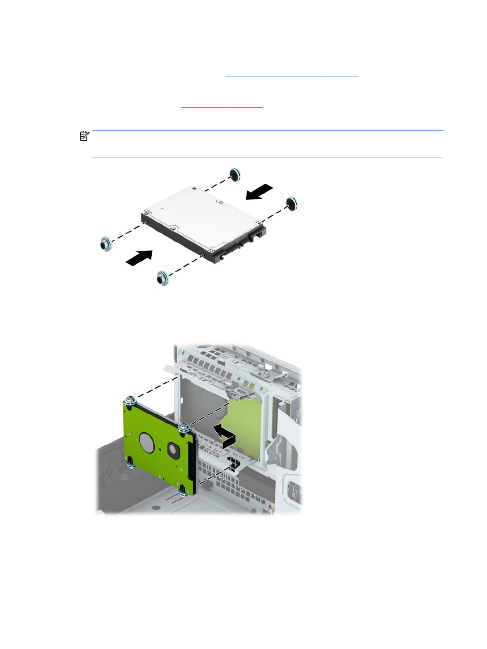
4. Install four black and blue M3 isolation mounting guide screws (two on each side of the drive).
NOTE: M3 metric isolation mounting guide screws can be purchased from HP.
When replacing a drive, transfer the four mounting screws from the old drive to the new drive.
5. Rotate the drive cage to its upright position.
6. Align the mounting screws on the drive with the J-slots on the sides of the drive bay. Press the drive up
into the drive bay then slide it forward until it locks in place.
44 Chapter 4 Removal and replacement procedures: Small Form Factor

7. Connect the power cable (1) and data cable (2) to the back of the hard drive.
NOTE: If the 2.5-inch hard drive is the primary drive, connect the other end of the data cable to the
dark blue SATA connector on the system board labeled SATA0 . If it is a secondary hard drive, connect the
other end of the data cable to one of the light blue SATA connectors on the system board.
8. Rotate the drive cage back down to its normal position.
CAUTION: Be careful not to pinch any cables or wires when rotating the drive cage down.
Drives 45

Power supply
Description
Power supply, 200W, 92% ecient
Power supply, 200W, 85% ecient
Power supply, 200W, standard
WARNING! To reduce potential safety issues, only the power supply provided with the computer, a
replacement power supply provided by HP, or a power supply purchased as an accessory from HP should be
used with the computer.
The power supply is located at the rear of the chassis. It is held in place by three Torx screws outside of the
chassis and a release lever inside of the chassis.
WARNING! Voltage is always present on the system board when the computer is plugged into an active AC
outlet. To avoid possible personal injury and damage to the equipment the power cord should be
disconnected from the computer and/or the AC outlet before opening the computer.
1. Prepare the computer for disassembly (Preparation for disassembly on page 19).
2. Remove the access panel (Access panel on page 20).
3. Rotate the drive cage to the upright position (Rotating the drive cage on page 32).
4. Disconnect all power cables from the following system board connectors:
(1): PWRCPU
(2): PWRCMD
(3): PWR
46 Chapter 4 Removal and replacement procedures: Small Form Factor
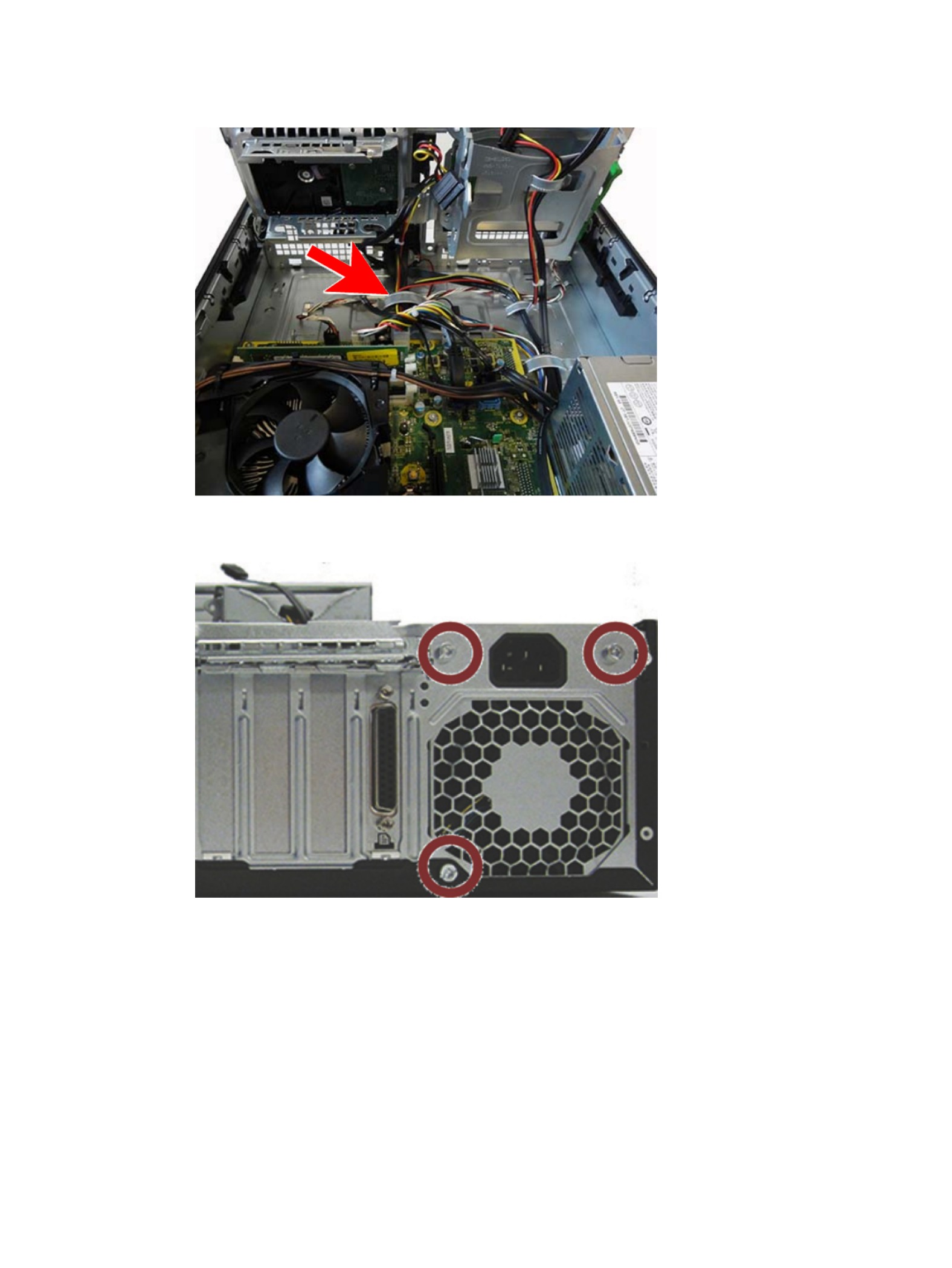
5. Release the power supply cables from the cable retaining clip under the drive cage.
6. From the outside, rear of the computer, remove the three Torx screws that secure the power supply to
the rear of the chassis.
7. From the inside of the chassis, press the release button at the front of the power supply .(1)
Power supply 47
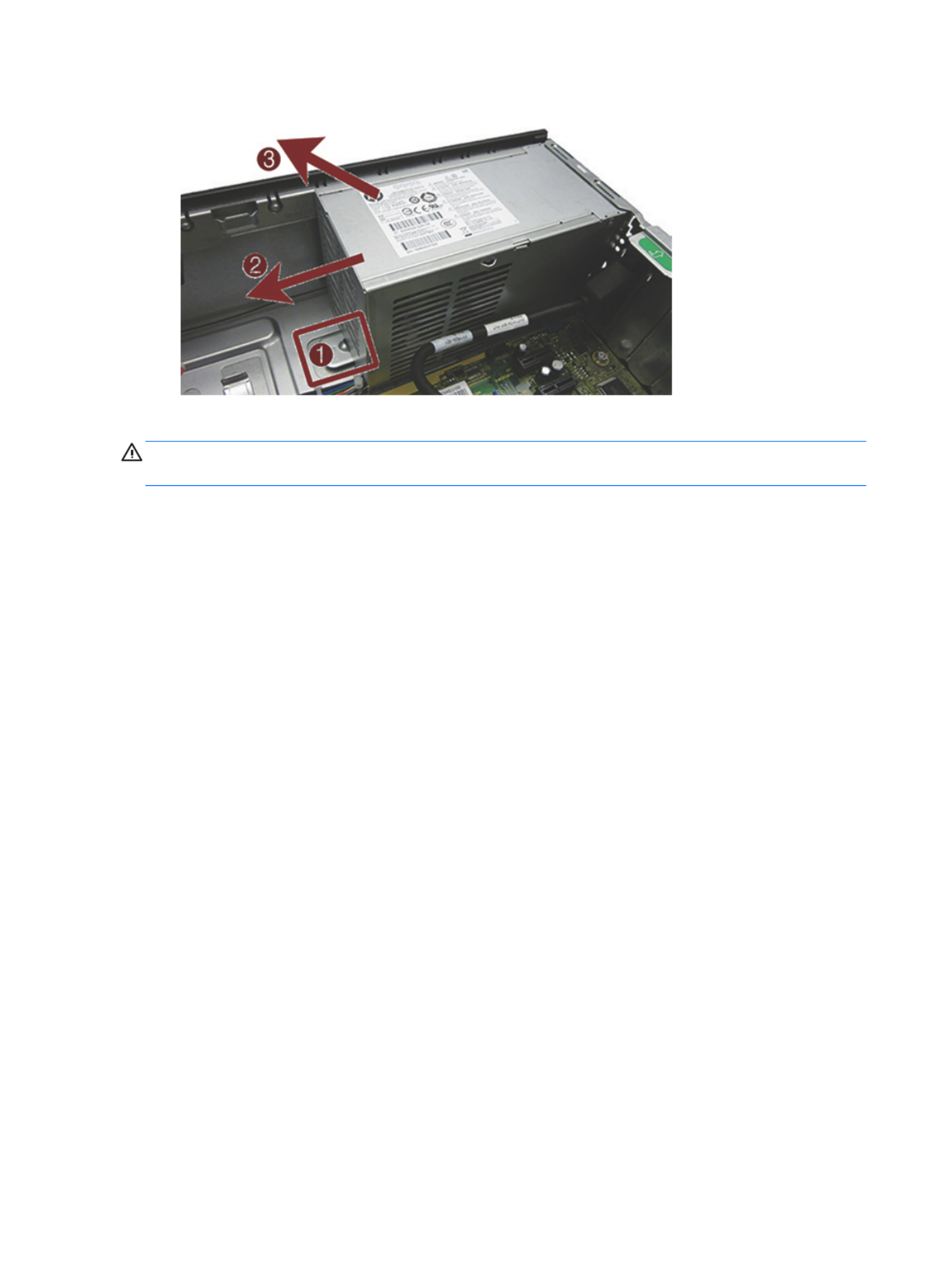
8. Slide the power supply forward , and then lift it out of the chassis .(2) (3)
To install the power supply, reverse the removal procedure.
CAUTION: When installing the power supply cables, make sure they are properly positioned in the clip under
the drive cage.
48 Chapter 4 Removal and replacement procedures: Small Form Factor

Rotating fan duct
The rotating fan duct sits between the fan sink and rear of the computer.
1. Prepare the computer for disassembly (Preparation for disassembly on page 19).
2. Remove the access panel (Access panel on page 20).
3. Rotate the fan duct upward.
4. Pull the duct away from the chassis to disengage the clips on the duct from the chassis.
To install the fan duct, insert the clips on the edge of the fan onto the metal posts on the chassis.
Rotating fan duct 49

Fan sink duct
The fan sink duct sits around the fan sink.
1. Prepare the computer for disassembly (Preparation for disassembly on page 19).
2. Remove the access panel (Access panel on page 20).
3. Rotate the fan duct upward.
4. Remove the power cable from the clips on the top of the duct.
5. Pull the tabs away from each other , and then lift the duct from around the fan sink .(1) (2)
Reverse these procedures to install the fan sink duct.
50 Chapter 4 Removal and replacement procedures: Small Form Factor

Front I/O assembly
1. Prepare the computer for disassembly (Preparation for disassembly on page 19).
2. Remove the access panel (Access panel on page 20).
3. Remove the front bezel (Front bezel on page 21).
4. Rotate the drive cage to its upright position (Rotating the drive cage on page 32).
5. Disconnect the cables from the system board as follows:
(1): Blue connector labeled FRONT USB 3.0
(2): Yellow connector labeled FRONT USB
(3): Blue connector labeled FRONT AUD
6. Remove the cables from the cable clips under the drive cage.
7. Remove the Torx T15 screw that secures the assembly to the front of the chassis.(1)
Front I/O assembly 51

8. Press the tab on the right side of the assembly to disengage it from the chassis.(2)
9. Push the assembly into the chassis, and then remove it from the chassis.
To install the assembly, insert the assembly from the inside of the chassis, and then pull the tab on the right
side of the assembly out the front of the chassis. Push the left side until it clicks into place.
NOTE: Be sure to correctly route the cables beneath the drive cage when reinstalling the assembly. Proper
cable routing prevents damage to the cables and allows the drive cage to close properly.
52 Chapter 4 Removal and replacement procedures: Small Form Factor

Power switch assembly
1. Prepare the computer for disassembly (Preparation for disassembly on page 19).
2. Remove the access panel (Access panel on page 20).
3. Remove the front bezel (Front bezel on page 21).
4. Rotate the drive cage to its upright position (Rotating the drive cage on page 32).
5. Disconnect the cable from the system board connector labeled PB/LED.
6. Remove the cable from the cable clips under the drive cage.
Power switch assembly 53
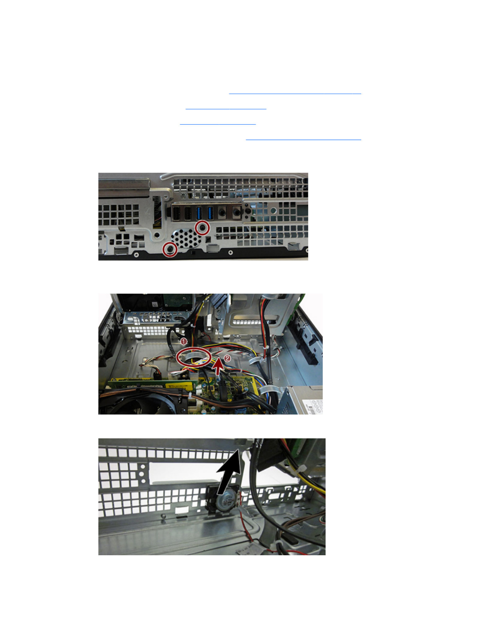
Speaker
The speaker is attached to the front of the chassis under the rotating drive cage.
1. Prepare the computer for disassembly (Preparation for disassembly on page 19).
2. Remove the access panel (Access panel on page 20).
3. Remove the front bezel (Front bezel on page 21).
4. Rotate the drive cage to its upright position (Rotating the drive cage on page 32).
5. From the outside, front of the chassis, remove the two Torx screws that secure the speaker to the
chassis.
6. On the inside of the chassis, lift the metal clip that secures the speaker cable, and then disconnect (1)
the speaker wire from the white system board connector labeled SPKR .(2)
7. Lift the speaker from the inside of the chassis to remove it.
To install the speaker, reverse the removal procedures.
Speaker 55
Termékspecifikációk
| Márka: | HP |
| Kategória: | Asztali |
| Modell: | ProDesk P1G57EA |
Szüksége van segítségre?
Ha segítségre van szüksége HP ProDesk P1G57EA, tegyen fel kérdést alább, és más felhasználók válaszolnak Önnek
Útmutatók Asztali HP

22 December 2024
22 December 2024
22 December 2024
22 December 2024
22 December 2024
22 December 2024
22 December 2024
6 December 2024
4 Október 2024
2 Október 2024
Útmutatók Asztali
- Asztali Samsung
- Asztali Sony
- Asztali Fujitsu
- Asztali Acer
- Asztali Sharkoon
- Asztali Sharp
- Asztali Lenovo
- Asztali Toshiba
- Asztali BenQ
- Asztali Apple
- Asztali Medion
- Asztali LC-Power
- Asztali Dell
- Asztali Gigabyte
- Asztali Tripp Lite
- Asztali BDI
- Asztali Microsoft
- Asztali Asus
- Asztali Vtech
- Asztali PEAQ
- Asztali Haier
- Asztali Supermicro
- Asztali AOC
- Asztali Asrock
- Asztali Kobo
- Asztali Viewsonic
- Asztali MSI
- Asztali ZTE
- Asztali Kogan
- Asztali Mio
- Asztali Moxa
- Asztali Razer
- Asztali JYSK
- Asztali Vorago
- Asztali NEC
- Asztali Elo
- Asztali Axis
- Asztali ECS
- Asztali Planar
- Asztali Zotac
- Asztali Kramer
- Asztali Alienware
- Asztali Emachines
- Asztali Parisot
- Asztali Trekstor
- Asztali Maxdata
- Asztali Woood
- Asztali Wehkamp
- Asztali InFocus
- Asztali Intel
- Asztali Targa
- Asztali Seagate
- Asztali Shuttle
- Asztali VXL
- Asztali Promethean
- Asztali Foxconn
- Asztali Ibm
- Asztali Advantech
- Asztali MP
- Asztali Elitegroup
- Asztali Smart Things
- Asztali ONYX
- Asztali System76
- Asztali Zoostorm
- Asztali Bestar
- Asztali Pelco
- Asztali Cybernet
- Asztali Altra
- Asztali Dell Wyse
- Asztali AOpen
- Asztali NComputing
- Asztali MvixUSA
- Asztali Faytech
- Asztali AIS
- Asztali Wyse
- Asztali Kendall Howard
Legújabb útmutatók Asztali

9 Április 2025
2 Április 2025

1 Április 2025

30 Március 2025
28 Március 2025
18 Március 2025
13 Január 2025

12 Január 2025
12 Január 2025

12 Január 2025