Használati útmutató HP g7-2235ew
Olvassa el alább 📖 a magyar nyelvű használati útmutatót HP g7-2235ew (130 oldal) a laptop kategóriában. Ezt az útmutatót 7 ember találta hasznosnak és 2 felhasználó értékelte átlagosan 4.5 csillagra
Oldal 1/130

HP Pavilion g7 Notebook PC
Maintenance and Service Guide

© Copyright 2011 Hewlett-Packard
Development Company, L.P.
AMD, the AMD Arrow logo, Athlon,
Phenom, Sempron, Turion, and
combinations thereof, are trademarks of
Advanced Micro Devices, Inc. Bluetooth is a
trademark owned by its proprietor and used
by Hewlett-Packard Company under license.
Intel, Celeron, Core, and Pentium are
trademarks of Intel Corporation in the U.S.
and other countries. Microsoft and Windows
are U.S. registered trademarks of Microsoft
Corporation. SD Logo is a trademark of
its proprietor.
The information contained herein is subject
to change without notice. The only
warranties for HP products and services are
set forth in the express warranty statements
accompanying such products and services.
Nothing herein should be construed as
constituting an additional warranty. HP shall
not be liable for technical or editorial errors
or omissions contained herein.
First Edition: February 2011
Document Part Number: 635956-001

Safety warning notice
WARNING! To reduce the possibility of heat-related injuries or of overheating the device, do not
place the device directly on your lap or obstruct the device air vents. Use the device only on a hard, flat
surface. Do not allow another hard surface, such as an adjoining optional printer, or a soft surface,
such as pillows or rugs or clothing, to block airflow. Also, do not allow the AC adapter to contact the
skin or a soft surface, such as pillows or rugs or clothing, during operation. The device and the AC
adapter comply with the user-accessible surface temperature limits defined by the International
Standard for Safety of Information Technology Equipment (IEC 60950).
iii

iv Safety warning notice

Table of contents
1 Product description ........................................................................................................... 1
2 External component identification ..................................................................................... 8
Top ........................................................................................................................................ 9
Button ...................................................................................................................... 9
Keys ...................................................................................................................... 10
Lights ..................................................................................................................... 11
TouchPad ............................................................................................................... 12
Display ................................................................................................................................. 13
Front ..................................................................................................................................... 14
Left side ................................................................................................................................ 14
Right side .............................................................................................................................. 15
Bottom .................................................................................................................................. 16
3 Illustrated parts catalog .................................................................................................. 17
Service tag ............................................................................................................................ 17
Computer major components ................................................................................................... 18
Cable Kit .............................................................................................................................. 25
Display assembly subcomponents ............................................................................................. 26
Mass storage devices ............................................................................................................. 28
Miscellaneous parts ................................................................................................................ 29
Sequential part number listing .................................................................................................. 30
4 Removal and replacement procedures ............................................................................ 37
Preliminary replacement requirements ....................................................................................... 37
Tools required ......................................................................................................... 37
Service considerations ............................................................................................. 37
Plastic parts ............................................................................................. 37
Cables and connectors ............................................................................. 37
Drive handling ......................................................................................... 38
Grounding guidelines .............................................................................................. 38
v

Electrostatic discharge damage .................................................................. 38
Packaging and transporting guidelines ........................................ 40
Component replacement procedures ........................................................................................ 42
Service tag ............................................................................................................. 42
Computer feet ......................................................................................................... 43
Battery ................................................................................................................... 44
Optical drive .......................................................................................................... 45
Hard drive ............................................................................................................. 47
RTC battery ............................................................................................................ 49
Memory module ...................................................................................................... 50
WLAN module ........................................................................................................ 51
Keyboard ............................................................................................................... 53
Top cover ............................................................................................................... 57
Power button board ................................................................................................. 60
TouchPad button board ............................................................................................ 62
TouchPad LED board ............................................................................................... 63
Bluetooth module .................................................................................................... 65
Speakers ................................................................................................................ 67
LED board .............................................................................................................. 68
USB board ............................................................................................................. 70
Power connector cable ............................................................................................ 71
System board ......................................................................................................... 73
Optical drive cable ................................................................................................. 77
Fan and heat sink .................................................................................................... 79
Processor ............................................................................................................... 86
Display assembly .................................................................................................... 89
5 Setup Utility (BIOS) and System Diagnostics .................................................................... 97
Using Setup Utility .................................................................................................................. 97
Starting Setup Utility ................................................................................................ 97
Changing the language of Setup Utility ...................................................................... 97
Navigating and selecting in Setup Utility .................................................................... 98
Displaying system information ................................................................................... 98
Restoring factory settings in Setup Utility ..................................................................... 99
Exiting Setup Utility ................................................................................................. 99
Updating the BIOS .................................................................................................. 99
Determining the BIOS version .................................................................. 100
Downloading a BIOS update ................................................................... 100
Using System Diagnostics ...................................................................................................... 101
vi

6 Specifications ............................................................................................................... 102
Computer specifications ........................................................................................................ 102
17.3-inch display specifications ............................................................................................. 103
Hard drive specifications ...................................................................................................... 104
7 Backup and recovery .................................................................................................... 105
Restore ............................................................................................................................... 105
Creating restore media ......................................................................................................... 106
Performing a system restore ................................................................................................... 107
Restoring using the dedicated recovery partition (select models only) ........................... 107
Restoring using the restore media ............................................................................ 108
Changing the computer boot order .......................................................................... 108
Backing up and recovering your information ........................................................................... 109
Using Windows Backup and Restore ....................................................................... 110
Using Windows system restore points ...................................................................... 110
When to create restore points .................................................................. 110
Create a system restore point ................................................................... 111
Restore to a previous date and time .......................................................... 111
8 Power cord set requirements ........................................................................................ 112
Requirements for all countries ................................................................................................ 112
Requirements for specific countries and regions ....................................................................... 113
9 Recycling ...................................................................................................................... 114
Battery ................................................................................................................................ 114
Display ............................................................................................................................... 114
Index ............................................................................................................................... 120
vii

viii

1 Product description
Category Description Computer models
equipped with an
AMD processor
Computer models
equipped with an
Intel processor
Product Name HP Pavilion g7 Notebook PC √ √
Processors AMD Athlon II P360 2.30-GHz processor
(1.0-MB L2 cache, 1066-MHz, 3.2GT/sec,
dual core, 25 W)
√
AMD Athlon II P340 2.20-GHz processor
(1.0-MB L2 cache, 1066-MHz, 3.2GT/sec,
dual core, 25 W)
√
AMD Phenom II N870 2.30-GHz processor
(1.5-MB L2 cache, 1333-MHz, 3.6GT/sec,
triple core, 35 W)
√
AMD Phenom II N970 2.20-GHz processor
(2.0-MB L2 cache, 1333-MHz, 3.6GT/sec,
quad core, 35 W)
√
AMD Phenom II P860 2.00-GHz processor
(1.5-MB L2 cache, 1333-MHz, 3.6GT/sec,
triple core, 25 W)
√
AMD Phenom II N660 3.00-GHz processor
(2.0-MB L2 cache, 1333-MHz, 3.6GT/sec,
dual core, 35 W)
√
AMD Phenom II N850 2.20-GHz processor
(1.5-MB L2 cache, 1333-MHz, 3.6GT/sec,
triple core, 35 W)
√
AMD Phenom II P650 2.60-GHz processor
(2.0-MB L2 cache, 1066-MHz, 3.6GT/sec,
triple core, 25 W)
√
AMD Phenom II P960 1.80-GHz processor
(2.0-MB L2 cache, 1066-MHz, 3.6GT/sec,
quad core, 25 W)
√
AMD Turion II P560 2.50-GHz processor
(2.0-MB L2 cache, 1066-MHz, 3.6GT/sec,
dual core, 25 W)
√
1

Category Description Computer models
equipped with an
AMD processor
Computer models
equipped with an
Intel processor
AMD V160 2.40-GHz processor (512-KB
L2 cache, 1066-MHz 3.2-GT/sec,
single core, 25 W)
√
AMD V140 2.30-GHz processor (512-KB
L2 cache, 1066-MHz 3.2-GT/sec,
single core, 25 W)
√
Intel Core i3-2310M 2.10-GHz processor
(3.0-MB L3 cache, dual core, 35 W)
√
Intel Core i3-380M 2.53-GHz processor (3.0-
MB L3 cache, dual core, 35 W)
√
Intel Core i3-390M 2.66-GHz processor (3.0-
MB L3 cache, dual core, 35 W)
√
Intel Core i5-2410M 2.30-GHz (SC turbo up
to 2.90-GHz) processor (3.0-MB L3 cache,
dual core, 35 W)
√
Intel Core i5-2520M 2.50-GHz (SC turbo up
to 3.20-GHz) processor (3.0-MB L3 cache,
dual core, 35 W)
√
Intel Core i5-2540M 2.60-GHz (SC turbo up
to 3.30-GHz) processor (3.0-MB L3 cache,
dual core, 35 W)
√
Intel Core i5-480M 2.66-GHz (SC turbo up to
2.93-GHz) processor (3.0-MB L3 cache,
dual core, 35 W)
√
Intel Core i7-2620M 2.70-GHz (SC turbo up
to 3.40-GHz) processor (4.0-MB L3 cache,
dual core, 35 W)
√
Intel Pentium P6200 2.13-GHz processor (3.0-
MB L3 cache, dual core, 35 W)
√
Intel Pentium P6300 2.26-GHz processor (3.0-
MB L3 cache, dual core, 35 W)
√
Chipset Northbridge: AMD RS880MD
Southbridge: AMD SB820M
√
Intel® HM65 and HM55 Express chipset √
Graphics Internal graphics: ATi Mobility Radeon™
HD 4250 graphics supporting DX10.1
√
Internal graphics:
●Intel HD Graphics 3000
●Intel HD Graphics 100
●Intel HD Graphics
√
2 Chapter 1 Product description

Category Description Computer models
equipped with an
AMD processor
Computer models
equipped with an
Intel processor
Switchable discrete graphics:
●ATI Mobility Radeon HD 6470M with
1024-MB of discrete video memory
(128-MB × 16 DDR3 @ 900 MHz × 4
PCs), 64-bit S3 package,
muxless switchable
●ATi Mobility Radeon HD 6470M with
512-MB of discrete video memory (64-
MB × 16 DDR3 @ 900 MHz × 4 PCs),
64-bit S3 package, muxless switchable
√ √
Supports DX11 √
Support HD decode, DX11, and HDMI √
Panel 17.3-in, high-definition+ (HD+), light-emitting
diode (LED), SVA BrightView (1600×900)
display; typical brightness: 200 nits
All display assemblies include 2 wireless local
area network (WLAN) antenna cables
Supports 16:9 ultra wide aspect ratio
√ √
Memory 2 customer-accessible/upgradable memory
module slots
√ √
Supports dual-channel memory √ √
Supports up to 8192 GB of system RAM √ √
DDR3/1333-MHz √ √
Supports the following configurations:
●8192-MB total system memory (4096×2;
not supported on a 32-bit
operating system)
●6144-MB total system memory (4096×1
+ 2048×1; not supported on a 32-bit
operating system)
●4096-MB total system memory (4096×1
or 2048×2)
●3072-MB total system memory (2048×1
+ 1024×1)
●2048-MB total system memory (2048×1
or 1024×2)
●1024-MB total system memory (1024×1;
not supported on a 64-bit
operating system)
√ √
3

Category Description Computer models
equipped with an
AMD processor
Computer models
equipped with an
Intel processor
Hard drives Supports 6.35-cm (2.5-in) hard drives in
12.7-mm (.50-in), 9.5-mm (.37-in), and
7.0-mm (.28-in) thicknesses
√ √
Customer-accessible √ √
Serial ATA √ √
Supports the following configurations:
●750 GB, 5400 rpm (9.5 mm)
●640 GB, 5400 rpm (9.5 mm)
●500 GB, 7200 and 5400 rpm (9.5 mm)
●320 GB, 7200 (7.0 mm) and 5400 rpm
(9.5 mm)
●250 GB, 7200 and 5400 rpm (7.0 mm)
√ √
Optical drive Fixed √ √
Serial ATA √ √
12.7-mm tray load √ √
Blu-ray ROM with LightScribe DVD ±R/RW
Super Multi Double-Layer Drive
√ √
DVD±RW and CD-RW Super Multi Double-
Layer Combo Drive with LightScribe
√ √
Audio and video Single digital microphone √ √
HD audio √ √
HP-branded Altec/Lansing speakers √ √
Supports Microsoft Premium requirements √ √
HP VGA webcam (fixed, no tilt with activity
LED, 640×480 by 24 frames per second
√ √
Ethernet Integrated 10/100 network interface card
(NIC)
√ √
Wireless Integrated wireless local area network
(WLAN) options by way of wireless module
√ √
Two WLAN antennas built into display
assembly
√ √
4 Chapter 1 Product description

Category Description Computer models
equipped with an
AMD processor
Computer models
equipped with an
Intel processor
Support for the following WLAN formats:
●Broadcom 4313 802.11b/g/n 1×1
WiFi and 2070 Bluetooth 2.1+EDR
Combo adapter (BT3.0+HS ready)
●Ralink 5390GN 802.11b/g/n 1×1
WiFi Adapter
●Ralink RT3090BC4 802.11b/g/n 1×1
WiFi and Bluetooth 2.1+EDR Combo
Adapter (BT3.0+HS ready)
√ √
Support for the following WLAN formats:
●Atheros 9285G 802.11b/g/n 1×1
WiFi Adapter
●Atheros AR8002WB-1NGB 802.11b/
g/n 1×1 WiFi and Bluetooth 2.1+EDR
Combo Adapter (BT3.0+HS ready)
●Broadcom 4313 802.11b/g/n 1×1
WiFi Adapter
●Realtek RTL8191SE 802.11b/g/n 1×1
WiFi Adapter
●Realtek 8188BC8 802.11a/b/g/n 2×2
WiFi and Bluetooth 3.0+HS Combo
Adapter
√
Support for the following WLAN formats:
●Intel Centrino Wireless-N 1000 WLAN
module
●Intel Centrino Advanced-N 6230
●Intel Centrino Wireless-N 1000
√
External media
card
HP Multi-Format Digital Media Reader
supports the following digital card formats:
●Secure Digital (SD) Memory Card
●Secure Digital High Capacity (SDHC)
Memory Card
●Secure Digital Extended Capacity
(SDXC) Memory Card
●MultiMediaCard (MMC)
√ √
5

Category Description Computer models
equipped with an
AMD processor
Computer models
equipped with an
Intel processor
Ports ●3-pin AC power
●Audio-in (mono microphone)
●Audio-out (stereo headphone)
●HDMI version 1.4 supporting up to
1080p, 1920 ×1200 @ 60Hz and
1920 ×1200 @ 60Hz in DVI mode
●RJ-45 (Ethernet, includes link and activity
lights)
●USB 2.0 (3 ports)
●VGA (Dsub 15 pin) supporting
2048×1056 external resolution @ 75
Hz, 1920 ×1200 external resolution @
60Hz, hot plug and unplug and auto-
detection for correct output to wide-
aspect vs. standard aspect video
√ √
Keyboard/
pointing devices
Full-size, textured, pocket, keyboard with full
numeric keypad
√ √
TouchPad with multi-touch gestures, 2-finger
scrolling, and pinch-zoom enabled
√ √
Taps enabled by default √ √
Power
requirements
90W slim travel AC adapter with localized
cable plug support (3-wire plug with ground
pin, supports 3-pin DC connector)
65 W slim travel AC adapter with localized
cable plug support (3-wire plug with ground
pin, supports 3-pin DC connector)
√ √
Support for the following batteries:
●6-cell, 55-Whr, 2.55-Ah Li-ion battery
●6-cell, 47-Whr, 2.20-Ah Li-ion battery
√ √
Security Security cable slot √ √
Supports Intel AT-p Ready √
Operating
system
Preinstalled:
●Windows 7 Home Premium 64-bit
●Windows 7 Professional 64-bit
√
6 Chapter 1 Product description

Category Description Computer models
equipped with an
AMD processor
Computer models
equipped with an
Intel processor
Preinstalled:
●Windows 7 Home Basic (64- and 32-bit)
●Windows 7 Home Premium (64- and 32-
bit)
●Windows 7 Professional (64- and 32-bit)
●Windows 7 Starter 32-bit
●FreeDOS
√
Serviceability End-user replaceable parts:
●AC adapter
●Battery
●Hard drive
●Memory modules (2)
●Optical drive
●WLAN module
√ √
7

2 External component identification
8 Chapter 2 External component identification

Top
Button
Component Description
Power button ●When the computer is off, press the button to turn on
the computer.
●When the computer is on, press the button briefly to
initiate Sleep.
●When the computer is in the Sleep state, press the
button briefly to exit Sleep.
●When the computer is in Hibernation, press the
button briefly to exit Hibernation.
If the computer has stopped responding and Windows
shutdown procedures are ineffective, press and hold the
power button for at least 5 seconds to turn off
the computer.
To learn more about your power settings, select Start >
Control Panel > System and Security > Power
Options, or refer to the HP Notebook Reference Guide.
Top 9

Keys
Item Component Description
(1) esc key Displays system information when pressed in combination
with the fn key.
(2) fn key Displays system information when pressed in combination
with the esc key.
(3) Windows logo key Displays the Windows Start menu.
(4) Action keys Execute frequently used system functions.
(5) Windows applications key Displays a shortcut menu for items beneath the pointer.
(6) Integrated numeric keypad Can be used like an external numeric keypad.
10 Chapter 2 External component identification

Lights
Item Component Description
(1) TouchPad light ●Amber: The TouchPad is off.
●Off: The TouchPad is on.
(2) Caps lock light ●White: Caps lock is on.
●Off: Caps lock is off.
(3) Power light ●White: The computer is on.
●Blinking white: The computer is in the Sleep state.
●Off: The computer is off or in Hibernation.
(4) Wireless light ●White: An integrated wireless device, such as a
WLAN device and/or a Bluetooth device, is on.
●Amber: All wireless devices are off.
Top 11

TouchPad
Item Component Description
(1) TouchPad light ●Amber: The TouchPad is off.
●On: The TouchPad is on.
(2) TouchPad on/off button Turns the TouchPad on and off. Quickly double-tap the
TouchPad on/off button to turn the TouchPad on and off.
(3) TouchPad zone Moves the pointer and selects or activates items on the
screen.
(4) Left TouchPad button Functions like the left button on an external mouse.
(5) Right TouchPad button Functions like the right button on an external mouse.
12 Chapter 2 External component identification
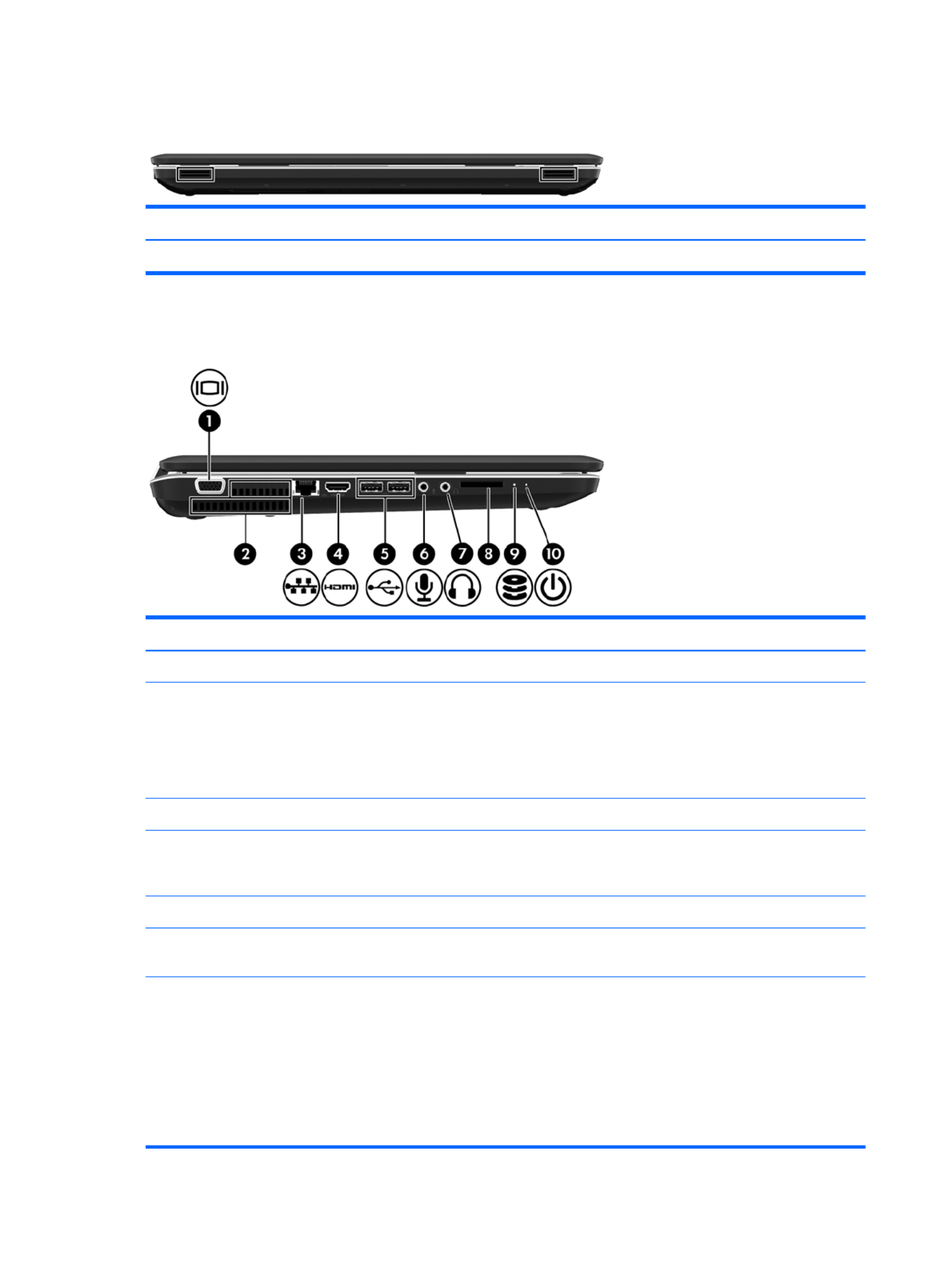
Front
Component Description
Speakers (2) Produce sound.
Left side
Item Component Description
(1) External monitor port Connects an external VGA monitor or projector.
(2) Vents (2) Enable airflow to cool internal components.
NOTE: The computer fan starts up automatically to cool
internal components and prevent overheating. It is normal
for the internal fan to cycle on and off during routine
operation.
(3) RJ-45 (network) jack Connects a network cable.
(4) HDMI port Connects an optional video or audio device, such as a
high-definition television, or any compatible digital or
audio component.
(5) USB ports (2) Connect optional USB devices.
(6) Audio-in (microphone) jack Connects an optional computer headset microphone,
stereo array microphone, or monaural microphone.
(7) Audio-out (headphone) jacks (2) Produce sound when connected to optional powered
stereo speakers, headphones, ear buds, a headset, or
television audio.
WARNING! To reduce the risk of personal injury,
adjust the volume before putting on headphones,
earbuds, or a headset. For additional safety information,
refer to the Regulatory, Safety, and Environmental
Notices.
14 Chapter 2 External component identification
Item Component Description
(8) Digital Media Slot Supports the following digital card formats:
●Secure Digital (SD) Memory Card
●Secure Digital High Capacity (SDHC) Memory Card
●Secure Digital Extended Capacity (SDXC) Memory
Card
●MultiMediaCard
(9) Drive light Blinking white: The hard drive is being accessed.
(10) Power light ●White: The computer is on.
●Blinking white: The computer is in the Sleep state.
●Off: The computer is off or in Hibernation.
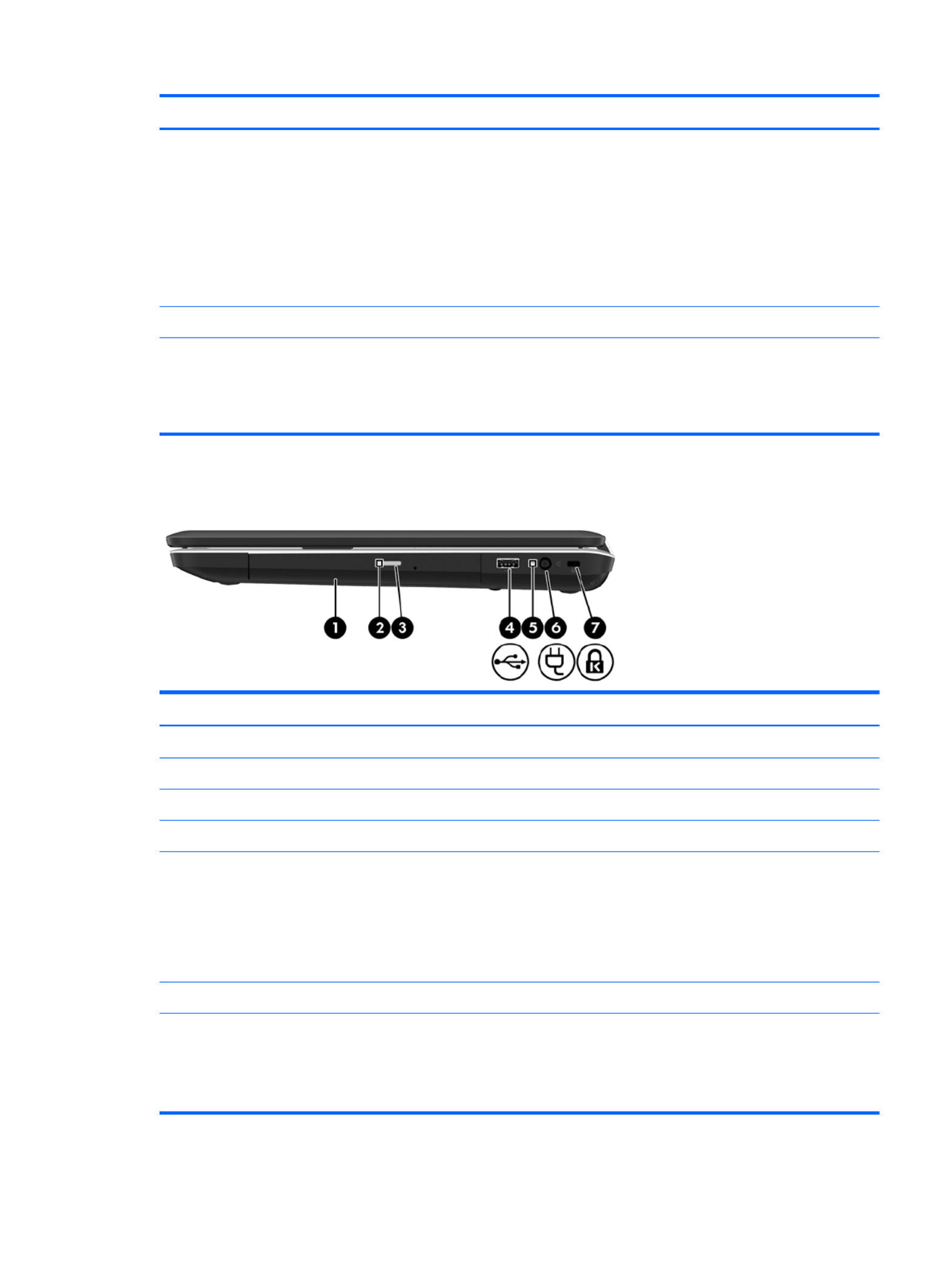
Right side
Item Component Description
(1) Optical drive Reads and writes to an optical disc.
(2) Optical drive light Blinking: The optical drive is being accessed.
(3) Optical drive eject button Opens the optical drive.
(4) USB port Connects an optional USB device.
(5) AC adapter light ●White: The computer is connected to external power
and the battery is fully charged.
●Blinking white: The battery has reached a low
battery level.
●Amber: A battery is charging.
(6) Power connector Connects an AC adapter.
(7) Security cable slot Connects an optional security cable.
NOTE: The security cable is designed to act as a
deterrent, but it may not prevent the computer from being
mishandled or stolen.
Right side 15

Bottom
Item Component Description
(1) Battery bay Holds the battery.
(2) Battery release latch Releases the battery from the battery bay.
(3) Vents (4) Enable airflow to cool internal components.
NOTE: The computer fan starts up automatically to cool
internal components and prevent overheating. It is normal
for the internal fan to cycle on and off during routine
operation.
(4) Hard drive bay Holds the hard drive, the memory module slots, and the
WLAN module.
CAUTION: To prevent an unresponsive system, replace
the wireless module only with a wireless module
authorized for use in the computer by the governmental
agency that regulates wireless devices in your country or
region. If you replace the module and then receive a
warning message, remove the module to restore
computer functionality, and then contact technical support
through Help and Support.
16 Chapter 2 External component identification

3 Illustrated parts catalog
Service tag
When ordering parts or requesting information, provide the computer serial number and model
description provided on the service tag.
Item Description Function
(1) Serial number (s/n) This is an alphanumeric identifier that is unique to
each product.
(2) Part number/Product number (p/n) This number provides specific information about the
product's hardware components. The part number
helps a service technician to determine what
components and parts are needed.
(3) Model description: This is the alphanumeric identifier needed to locate
documents, drivers, and support for the computer.
(4) Warranty period This number describes the duration of the warranty
period for the computer.
Service tag 17

Computer major components
18 Chapter 3 Illustrated parts catalog

Item Component Spare part number
(1) 17.3-in, high definition (HD), light-emitting diode (LED), BrightView display assembly (includes
webcam, two microphones, and wireless antenna transceivers and cables)
In butter gold finish 640223-001
In charcoal gray finish 640226-001
In luminous rose finish 640225-001
In ocean drive finish 640224-001
In Pacific blue finish 640221-001
In pearl pink finish 640228-001
In pewter finish 640227-001
In Sonoma red finish 640220-001
In sweet purple finish 640222-001
NOTE: For more display assembly spare part information, see Display assembly subcomponents on page 26.
(2) Keyboard (includes keyboard cable):
Keyboard in black finish
For use in Belgium 640208-A41
For use in Canada 640208-121
For use in the Czech Republic 640208-221
For use in Denmark, Finland, and Norway 640208-DH1
For use in France 640208-051
For use in Germany 640208-041
For use in Greece 640208-DJ1
For use in Hungary 640208-211
For use in Israel 640208-BB1
For use in Italy 640208-061
For use in the Netherlands 640208-B31
For use in Portugal 640208-131
For use in Russia 640208-251
For use in Saudi Arabia 640208-171
For use in Slovenia 640208-BA1
For use in Spain 640208-071
For use in Switzerland 640208-BG1
For use in Turkey 640208-141
For use in the United Kingdom 640208-031
Computer major components 19

Item Component Spare part number
For use in the United States 640208-001
Keyboard in silver finish
For use in Belgium 647630-A41
For use in Canada 647630-121
For use in the Czech Republic 647630-221
For use in Denmark, Finland, and Norway 647630-DH1
For use in France 647630-051
For use in Germany 647630-041
For use in Greece 647630-DJ1
For use in Hungary 647630-211
For use in Israel 647630-BB1
For use in Italy 647630-061
For use in the Netherlands 647630-B31
For use in Portugal 647630-131
For use in Russia 647630-251
For use in Saudi Arabia 647630-171
For use in Slovenia 647630-BA1
For use in Spain 647630-071
For use in Switzerland 647630-BG1
For use in Turkey 647630-141
For use in the United Kingdom 647630-031
For use in the United States 647630-001
(3) Top cover (includes TouchPad and TouchPad cable):
In butter gold finish 641401-001
In charcoal gray finish 641404-001
In luminous rose finish 641403-001
In ocean drive finish 641402-001
In Pacific blue finish 641399-001
In pearl pink finish 641406-001
In pewter finish 641405-001
In Sonoma red finish 640193-001
In sweet purple finish 641400-001
20 Chapter 3 Illustrated parts catalog

Item Component Spare part number
(4) Power button board (includes cable) 640212-001
(5) TouchPad LED board (includes cable) 640213-001
(6) TouchPad button board (includes cable) 640214-001
Cable Kit, includes: 640206-001
(7a) TouchPad cable
(7b) Optical drive cable
(7c) Hard drive connector cable
NOTE: See Cable Kit on page 25 for more Cable Kit spare part information.
(8) Speaker Kit (includes left and right speakers and cable) 641396-001
(9) Bluetooth module (for use only with computer models equipped with an
Intel processor)
NOTE: The Bluetooth module spare part kit does not include the Bluetooth
module cable. The Bluetooth module cable is available using spare part number
602538-001.
537921-001
(10) Bluetooth module cable (for use only with computer models equipped with an
Intel processor)
602538-001
(11) USB board (includes cable) 640211-001
(12) Power connector cable 641394-001
(13) System board (includes replacement thermal material):
For use only with computer models equipped with an AMD processor:
For use only with computer models equipped with a graphics subsystem with 1024-MB
of discrete video memory
638855-001
For use only with computer models equipped with a graphics subsystem with 512-MB
of discrete video memory
638854-001
For use only with computer models equipped with a graphics subsystem with UMA
video memory
638856-001
For use only with computer models equipped with an Intel processor:
For use only with computer models equipped with an HM65 chipset and a graphics
subsystem with 1024-MB of discrete video memory
636375-001
For use only with computer models equipped with an HM65 chipset and a graphics
subsystem with 512-MB of discrete video memory
636374-001
For use only with computer models equipped with an HM55 chipset and a graphics
subsystem with 1024-MB of discrete video memory
636372-001
For use only with computer models equipped with an HM55 chipset and a graphics
subsystem with 512-MB of discrete video memory
636371-001
For use only with computer models equipped with an HM65 chipset and a graphics
subsystem with UMA video memory
636373-001
Computer major components 21

Item Component Spare part number
For use only with computer models equipped with an HM55 chipset and a graphics
subsystem with UMA video memory
636370-001
Thermal Material Kit (includes replacement thermal paste and pads) 634433-001
(14) Processor (includes replacement thermal material)
AMD Athlon II P360 2.30-GHz processor (1.0-MB L2 cache, 1066-MHz, 3.2GT/sec,
dual core, 25 W)
636635-001
AMD Athlon II P340 2.20-GHz processor (1.0-MB L2 cache, 1066-MHz, 3.2GT/sec,
dual core, 25 W)
616343-001
AMD Phenom II N870 2.30-GHz processor (1.5-MB L2 cache, 1333-MHz, 3.6GT/
sec, triple core, 35 W)
635495-001
AMD Phenom II N970 2.20-GHz processor (2.0-MB L2 cache, 1333-MHz, 3.6GT/
sec, quad core, 35 W)
635496-001
AMD Phenom II P860 2.00-GHz processor (1.5-MB L2 cache, 1333-MHz, 3.6GT/sec,
triple core, 25 W)
634688-001
AMD Phenom II N660 3.00-GHz processor (2.0-MB L2 cache, 1333-MHz, 3.6GT/
sec, dual core, 35 W)
635494-001
AMD Phenom II N850 2.20-GHz processor (1.5-MB L2 cache, 1333-MHz, 3.6GT/
sec, triple core, 35 W)
616345-001
AMD Phenom II P650 2.60-GHz processor (2.0-MB L2 cache, 1066-MHz, 3.6GT/sec,
triple core, 25 W)
634687-001
AMD Phenom II P960 1.80-GHz processor (2.0-MB L2 cache, 1066-MHz, 3.6GT/sec,
quad core, 25 W)
634689-001
AMD Turion II P560 2.50-GHz processor (2.0-MB L2 cache, 1066-MHz, 3.6GT/sec,
dual core, 25 W)
634691-001
AMD V160 2.40-GHz processor (512-KB L2 cache, 1066-MHz 3.2-GT/sec,
single core, 25 W)
616333-001
AMD V140 2.30-GHz processor (512-KB L2 cache, 1066-MHz 3.2-GT/sec,
single core, 25 W)
636634-001
Intel Core i3-2310M 2.10-GHz processor (3.0-MB L3 cache, dual core, 35 W) 638037-001
Intel Core i3-380M 2.53-GHz processor (3.0-MB L3 cache, dual core, 35 W) 625823-001
Intel Core i3-390M 2.66-GHz processor (3.0-MB L3 cache, dual core, 35 W) 634692-001
Intel Core i5-2410M 2.30-GHz (SC turbo up to 2.90-GHz) processor (3.0-MB
L3 cache, dual core, 35 W)
638039-001
Intel Core i5-2520M 2.50-GHz (SC turbo up to 3.20-GHz) processor (3.0-MB
L3 cache, dual core, 35 W)
631253-001
Intel Core i5-2540M 2.60-GHz (SC turbo up to 3.30-GHz) processor (3.0-MB
L3 cache, dual core, 35 W)
631255-001
Intel Core i5-480M 2.66-GHz (SC turbo up to 2.93-GHz) processor (3.0-MB L3 cache,
dual core, 35 W)
634693-001
22 Chapter 3 Illustrated parts catalog

Item Component Spare part number
Intel Core i7-2620M 2.70-GHz (SC turbo up to 3.40-GHz) processor (4.0-MB
L3 cache, dual core, 35 W)
631252-001
Intel Pentium P6200 2.13-GHz processor (3.0-MB L3 cache, dual core, 35 W) 625831-001
Intel Pentium P6300 2.26-GHz processor (3.0-MB L3 cache, dual core, 35 W) 635500-001
(15) Fan (includes replacement thermal material) 639460-001
(16) Heat sink (includes replacement thermal material)
For use only with computer models equipped with an AMD processor:
For use only with computer models equipped with a graphics subsystem with discrete
video memory
639462-001
For use only with computer models equipped with a graphics subsystem with UMA
video memory
639463-001
For use only with computer models equipped with an Intel processor:
For use only with computer models equipped with an HM65 chipset and a graphics
subsystem with discrete video memory
641141-001
For use only with computer models equipped with an HM65 chipset and a graphics
subsystem with UMA video memory
641140-001
For use only with computer models equipped with an HM55 chipset and a graphics
subsystem with discrete video memory
637190-001
For use only with computer models equipped with an HM55 chipset and a graphics
subsystem with UMA video memory
637189-001
(17) LED board (includes cable) 640215-001
(18) Base enclosure (includes battery release latch, heat sink, replacement
thermal material, and 4 rubber feet)
640203-001
Rubber Feet Kit (not illustrated, includes 4 rubber feet) 639455-001
(19) Battery:
6-cell, 55-Whr, 2.55-Ah Li-ion battery 593554-001
6-cell, 47-Whr, 2.20-Ah Li-ion battery 593553-001
(20) RTC battery (includes cable and double-sided tape) 637193-001
(21) Hard drive (2.5-in, 7.0-mm, SATA, does not include hard drive connector cable, isolators, or Mylar shield):
For use with all computer models:
750-GB, 5400-rpm 644351-001
640-GB, 5400-rpm 637312-001
500-GB, 7200-rpm 644685-001
320-GB, 7200-rpm 645089-001
320-GB, 5400-rpm 645086-001
250-GB, 7200-rpm 645091-001
Computer major components 23

Item Component Spare part number
640-GB, 7200-rpm for use only with computer models equipped with an
AMD processor
644350-001
Hard Drive Hardware Kit (not illustrated, includes front and rear isolators and
Mylar shield)
645377-001
(22) Memory modules (2, DDR3, 10600, 1333-MHz):
4 GB 621569-001
2 GB 621565-001
1 GB 639736-001
(23) Optical drive (includes bezel and bracket):
Blu-ray ROM with LightScribe DVD ±R/RW Super Multi Double-Layer Drive 640210-001
DVD±RW and CD-RW Super Multi Double-Layer Combo Drive with LightScribe 640209-001
(24) WLAN module:
For use on all computer models:
Broadcom 4313 802.11b/g/n 1×1 WiFi and 2070 Bluetooth 2.1+EDR Combo
adapter (BT3.0+HS ready)
600370-001
Ralink 5390GN 802.11b/g/n 1×1 WiFi Adapter 630703-001
Ralink RT3090BC4 802.11b/g/n 1×1 WiFi and Bluetooth 2.1+EDR Combo Adapter
(BT3.0+HS ready)
630705-001
For use only with computer models equipped with an AMD processor:
Atheros 9285G 802.11b/g/n 1×1 WiFi Adapter 605560-005
Atheros AR8002WB-1NGB 802.11b/g/n 1×1 WiFi and Bluetooth 2.1+EDR Combo
Adapter (BT3.0+HS ready)
593127-001
Broadcom 4313 802.11b/g/n 1×1 WiFi Adapter 593836-001
Realtek RTL8191SE 802.11b/g/n 1×1 WiFi Adapter 640926-001
Realtek 8188BC8 802.11a/b/g/n 2×2 WiFi and Bluetooth 3.0+HS Combo Adapter 602993-001
For use only with computer models equipped with an Intel processor:
Atheros 9285G 802.11b/g/n 1×1 WiFi Adapter 518436-001
Intel Centrino Advanced-N 6230 631956-001
Intel Centrino Wireless-N 1000 593530-001
(25) Service cover (includes 2 captive screws, secured by C-clips) — available in the Plastics Kit, spare part number
640216-001)
24 Chapter 3 Illustrated parts catalog

Cable Kit
Item Component Spare part number
Cable Kit, includes: 640206-001
(1) TouchPad cable
(2) Hard drive connector cable
(3) Optical drive cable
Cable Kit 25

Display assembly subcomponents
Item Component Spare part number
(1) Display bezel 640204-001
(2) Display hinge covers (2) 643698-001
(3) Webcam/microphone module 637197-001
(4) 17.3-in, HD, LED, BrightView display panel 641395-001
(5) Display Hinge Kit (includes left and right display hinges and brackets) 640207-001
(6) Display Cable Kit (includes display panel cable and webcam/microphone
module cable)
640205-001
(7) Antenna Kit (includes left and right wireless antenna cables and transceivers) 640192-001
26 Chapter 3 Illustrated parts catalog

Item Component Spare part number
(8) Display enclosure:
In butter gold finish 640197-001
In charcoal gray finish 640200-001
In luminous rose finish 640199-001
In ocean drive finish 640198-001
In Pacific blue finish 640195-001
In pearl pink finish 640202-001
In pewter finish 640201-001
In Sonoma red finish 640194-001
In sweet purple finish 640196-001
Display Screw Kit (not illustrated) 640218-001
Display assembly subcomponents 27
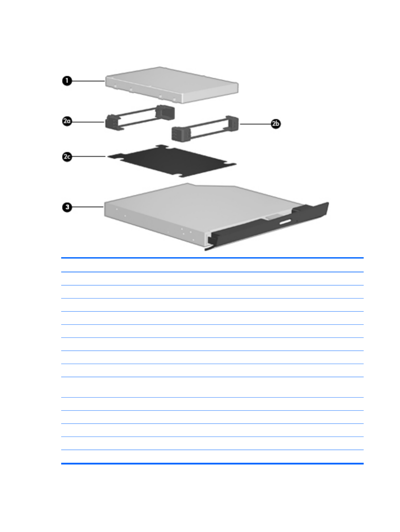
Mass storage devices
Item Component Spare part number
(1) Hard drive (2.5-in, 7.0-mm, SATA, does not include hard drive connector cable, isolators, or Mylar shield):
For use with all computer models:
750-GB, 5400-rpm 644351-001
640-GB, 5400-rpm 637312-001
500-GB, 7200-rpm 644685-001
320-GB, 7200-rpm 645089-001
320-GB, 5400-rpm 645086-001
250-GB, 7200-rpm 645091-001
640-GB, 7200-rpm for use only with computer models equipped with an
AMD processor
644350-001
Hard Drive Hardware Kit, includes: 639444-001
(2a) Hard drive front isolator
(2b) Hard drive rear isolator
(2c) Hard drive Mylar shield
(3) Optical drive (includes bezel and bracket):
28 Chapter 3 Illustrated parts catalog

Item Component Spare part number
Blu-ray ROM with LightScribe DVD ±R/RW Super Multi Double-Layer Drive 639449-001
DVD±RW and CD-RW Super Multi Double-Layer Combo Drive with LightScribe 639448-001
Miscellaneous parts
Component Spare part number
HP Smart AC adapter
90-W PFC RC V HP Smart AC adapter 609940-001
65-W RC V HP Smart AC adapter 609939-001
Power cord (3-pin, black, 1.83-m):
For use in Denmark 490371-081
For use in Europe 490371-021
For use in Israel 490371-BB1
For use in Italy 490371-061
For use in North America 490371-001
For use in South Africa 490371-AR1
For use in Switzerland 490371-111
For use in the United Kingdom and Singapore 490371-031
Screw Kit 640217-001
Miscellaneous parts 29

Sequential part number listing
Spare part number Description
490371-001 Power cord for use with all computer models in North America (3-pin, black, 1.83-m)
490371-021 Power cord for use only with computer models equipped with an Intel processor in Europe (3-pin,
black, 1.83-m)
490371-031 Power cord for use only with computer models equipped with an Intel processor in the United
Kingdom and Singapore (3-pin, black, 1.83-m)
490371-061 Power cord for use with all computer models in Italy (3-pin, black, 1.83-m)
490371-081 Power cord for use with all computer models in Denmark (3-pin, black, 1.83-m)
490371-111 Power cord for use only with computer models equipped with an Intel processor in Switzerland (3-
pin, black, 1.83-m)
490371-AR1 Power cord for use only with computer models equipped with an Intel processor in South Africa
(3-pin, black, 1.83-m)
490371-BB1 Power cord for use only with computer models equipped with an Intel processor in Israel (3-pin,
black, 1.83-m)
518436-001 Atheros 9285G 802.11b/g/n 1×1 WiFi Adapter for use only with computer models equipped
with an Intel processor
537921-001 Bluetooth module
NOTE: The Bluetooth module spare part kit does not include a Bluetooth module cable. The
Bluetooth module cable is available using spare part number 602538-001.
593127-001 Atheros AR8002WB-1NGB 802.11b/g/n 1×1 WiFi and Bluetooth 2.1+EDR Combo Adapter
(BT3.0+HS ready) for use only with computer models equipped with an AMD processor
593530-001 Intel Centrino Wireless-N 1000 WLAN module for use only on computer models equipped with
an Intel processor
593553-001 6-cell, 47-Whr, 2.20-Ah Li-ion battery
593554-001 6-cell, 55-Whr, 2.55-Ah Li-ion battery
593836-001 Broadcom 4313 802.11b/g/n 1×1 WiFi Adapter for use only on computer models equipped
with an AMD processor
600370-001 Broadcom 4313 802.11b/g/n 1×1 WiFi and 2070 Bluetooth 2.1+EDR Combo Adapter
(Bluetooth 3.0+HS ready)
602538-001 Bluetooth module cable
602993-001 Realtek 8188BC8 802.11a/b/g/n 2×2 WiFi and Bluetooth 3.0+HS Combo Adapter for use
only with computer models equipped with an AMD processor
605560-005 Atheros 9285G 802.11b/g/n 1×1 WiFi Adapter
609939-001 65-W RC V HP Smart AC adapter for use only with computer models equipped with an
AMD processor
609940-001 90-W PFC RC V HP Smart AC adapter for use with all computer models
30 Chapter 3 Illustrated parts catalog

Spare part number Description
616333-001 AMD V140 2.30-GHz processor (512-KB L2 cache, 1066-MHz 3.2-GT/sec, single core, 25 W;
includes replacement thermal material)
616343-001 AMD Athlon II P340 2.20-GHz processor (1.0-MB L2 cache, 1066-MHz, 3.2GT/sec, dual core,
25 W; includes replacement thermal material)
616345-001 AMD Phenom II N850 2.20-GHz processor (1.5-MB L2 cache, 1333-MHz, 3.6GT/sec,
triple core, 35 W; includes replacement thermal material)
621565-001 2-GB memory module (DDR3, 10600, 1333-MHz)
621569-001 4-GB memory module (DDR3, 10600, 1333-MHz)
625823-001 Intel i3-380M 2.53-GHz processor (3.0-MB L3 cache, dual core, 35 W; includes replacement
thermal material)
625831-001 Intel Pentium P6200 2.13-GHz processor (3.0-MB L3 cache, dual core, 35 W; includes
replacement thermal material)
630703-001 Ralink 5390GN 802.11b/g/n 1×1 WiFi Adapter for use only on computer models equipped
with an Intel processor
630705-001 Ralink RT3090BC4 802.11b/g/n 1×1 WiFi and Bluetooth 2.1+EDR Combo Adapter
(Bluetooth 3.0+HS ready)
631252-001 Intel i7-2620M 2.70-GHz (SC turbo up to 3.40-GHz) processor (4-MB L3 cache, dual core,
35 W; includes replacement thermal material)
631253-001 Intel i5-2520M 2.50-GHz (SC turbo up to 3.20-GHz) processor (3.0-MB L3 cache, dual core,
35 W; includes replacement thermal material)
631255-001 Intel i5-2540M 2.60-GHz (SC turbo up to 3.30-GHz) processor (3.0-MB L3 cache, dual core,
35 W; includes replacement thermal material)
631956-001 Intel Centrino Advanced-N 6230 WLAN module for use only on computer models equipped with
an Intel processor
634433-001 Thermal Material Kit (includes replacement thermal paste and pads)
634687-001 AMD Phenom II P650 2.60-GHz processor (2.0-MB L2 cache, 1066-MHz, 3.6GT/sec,
triple core, 25 W; includes replacement thermal material)
634688-001 AMD Phenom II P860 2.00-GHz processor (1.5-MB L2 cache, 1333-MHz, 3.6GT/sec,
triple core, 25 W; includes replacement thermal material)
634689-001 AMD Phenom II P960 1.80-GHz processor (2.0-MB L2 cache, 1066-MHz, 3.6GT/sec,
quad core, 25 W; includes replacement thermal material)
634691-001 AMD Turion II P560 2.50-GHz processor (2.0-MB L2 cache, 1066-MHz, 3.6GT/sec, dual core,
25 W; includes replacement thermal material)
634692-001 Intel i3-390M 2.66-GHz processor (3.0-MB L3 cache, dual core, 35 W; includes replacement
thermal material)
634693-001 Intel i5-480M 2.66-GHz (SC turbo up to 2.93-GHz) processor (3.0-MB L3 cache, dual core,
35 W; includes replacement thermal material)
635494-001 AMD Phenom II N660 3.00-GHz processor (2.0-MB L2 cache, 1333-MHz, 3.6GT/sec,
dual core, 35 W; includes replacement thermal material)
635495-001 AMD Phenom II N870 2.30-GHz processor (1.5-MB L2 cache, 1333-MHz, 3.6GT/sec,
triple core, 35 W; includes replacement thermal material)
Sequential part number listing 31

Spare part number Description
635496-001 AMD Phenom II N970 2.20-GHz processor (2.0-MB L2 cache, 1333-MHz, 3.6GT/sec,
quad core, 35 W; includes replacement thermal material)
635500-001 Intel Pentium P6300 2.26-GHz processor (3.0-MB L3 cache, dual core, 35 W; includes
replacement thermal material)
636370-001 System board for use only with computer models equipped with an Intel processor, HM55 chipset,
and a graphics subsystem with UMA video memory (includes replacement thermal material)
636371-001 System board for use only with computer models equipped with an Intel processor, HM55 chipset,
and a graphics subsystem with 512-MB of discrete video memory (includes replacement
thermal material)
636372-001 System board for use only with computer models equipped with an Intel processor, HM55 chipset,
and a graphics subsystem with 1024-MB of discrete video memory (includes replacement
thermal material)
636373-001 System board for use only with computer models equipped with an Intel processor, HM65 chipset,
and a graphics subsystem with UMA video memory (includes replacement thermal material)
636374-001 System board for use only with computer models equipped with an Intel processor, HM65 chipset,
and a graphics subsystem with 512-MB of discrete video memory (includes replacement
thermal material)
636375-001 System board for use only with computer models equipped with an Intel processor, HM65 chipset,
and a graphics subsystem with 512-MB of discrete video memory (includes replacement
thermal material)
636634-001 AMD V160 2.40-GHz processor (512-KB L2 cache, 1066-MHz 3.2-GT/sec, single core, 25 W;
includes replacement thermal material)
636635-001 AMD Athlon II P360 2.30-GHz processor (1.0-MB L2 cache, 1066-MHz, 3.2GT/sec, dual core,
25 W; includes replacement thermal material)
637189-001 System board for use only with computer models equipped with an Intel processor, HM55 chipset,
and a graphics subsystem with UMA video memory (includes replacement thermal material)
637190-001 System board for use only with computer models equipped with an Intel processor, HM55 chipset,
and a graphics subsystem with discrete video memory (includes replacement thermal material)
637193-001 RTC battery (includes cable and double-sided tape)
637197-001 Webcam/microphone module
637312-001 640-GB, 5400-rpm hard drive (2.5-in, SATA, does not include isolators or Mylar shield)
638037-001 Intel i3-2310M 2.10-GHz processor (3.0-MB L3 cache, dual core, 35 W; includes replacement
thermal material)
638039-001 Intel i5-2410M 2.30-GHz (SC turbo up to 2.90-GHz) processor (3.0-MB L3 cache, dual core,
35 W; includes replacement thermal material)
638854-001 System board for use only with computer models equipped with an AMD processor and a
graphics subsystem with 512-MB of discrete video memory (includes replacement
thermal material)
638855-001 System board for use only with computer models equipped with an AMD processor and a
graphics subsystem with 1024-MB of discrete video memory (includes replacement
thermal material)
32 Chapter 3 Illustrated parts catalog

Spare part number Description
638856-001 System board for use only with computer models equipped with an AMD processor and a
graphics subsystem with UMA video memory t thermal material)(includes replacemen
639455-001 Rubber Feet Kit (includes 4 rubber feet)
639460-001 Fan (includes replacement thermal material)
639462-001 Heat sink for use only with computer models equipped with an AMD processor and a graphics
subsystem with discrete video memory (includes replacement thermal material)
639463-001 Heat sink for use only with computer models equipped with an AMD processor and a graphics
subsystem with UMA video memory (includes replacement thermal material)
639736-001 1-GB memory module (DDR3, 10600, 1333-MHz)
640192-001 Antenna Kit (includes left and right wireless antenna cables and transceivers)
640193-001 Top cover in Sonoma red finish (includes TouchPad and TouchPad cable)
640194-001 Display enclosure in Sonoma red finish
640195-001 Display enclosure in Pacific blue finish
640196-001 Display enclosure in sweet purple finish
640197-001 Display enclosure in butter gold finish
640198-001 Display enclosure in ocean drive finish
640199-001 Display enclosure in luminous rose finish
640200-001 Display enclosure in charcoal gray finish
640201-001 Display enclosure in pewter finish
640202-001 Display enclosure in pearl pink finish
640203-001 Base enclosure (includes battery release latch, heat sink, replacement thermal material, and 4
rubber feet)
640204-001 Display bezel
640205-001 Display Cable Kit (includes display panel cable and webcam/microphone module cable)
640206-001 Cable Kit (includes hard drive connector cable, optical drive cable, and TouchPad cable)
NOTE: See Cable Kit on page 25 for more Cable Kit spare part information.
640207-001 Display Hinge Kit (includes left and right display hinges and brackets)
640208-001 Keyboard in black finish for use in the United States (includes keyboard cable)
640208-031 Keyboard in black finish for use in the United Kingdom and Singapore (includes keyboard cable)
640208-041 Keyboard in black finish for use in Germany (includes keyboard cable)
640208-051 Keyboard in black finish for use in France (includes keyboard cable)
640208-061 Keyboard in black finish for use in Italy (includes keyboard cable)
640208-071 Keyboard in black finish for use in Spain (includes keyboard cable)
640208-121 Keyboard in black finish for use in Canada (includes keyboard cable)
Sequential part number listing 33

Spare part number Description
640208-131 Keyboard in black finish for use in Portugal (includes keyboard cable)
640208-141 Keyboard in black finish for use in Turkey (includes keyboard cable)
640208-171 Keyboard in black finish for use in Saudi Arabia (includes keyboard cable)
640208-211 Keyboard in black finish for use in Hungary (includes keyboard cable)
640208-221 Keyboard in black finish for use in the Czech Republic (includes keyboard cable)
640208-251 Keyboard in black finish for use in Russia (includes keyboard cable)
640208-A41 Keyboard in black finish for use in Belgium (includes keyboard cable)
640208-B31 Keyboard in black finish for use in the Netherlands (includes keyboard cable)
640208-BA1 Keyboard in black finish for use in Slovenia (includes keyboard cable)
640208-BB1 Keyboard in black finish for use in Israel (includes keyboard cable)
640208-BG1 Keyboard in black finish for use in Switzerland (includes keyboard cable)
640208-DH1 Keyboard in black finish for use in Denmark, Finland, and Norway (includes keyboard cable)
640208-DJ1 Keyboard in black finish for use in Greece (includes keyboard cable)
640209-001 DVD±RW and CD-RW Super Multi Double-Layer Combo Drive with LightScribe
640210-001 Blu-ray ROM with LightScribe DVD ±R/RW Super Multi Double-Layer Drive
640211-001 USB board (includes cable)
640212-001 Power button board (includes cable)
640213-001 TouchPad LED board (includes cable)
640214-001 TouchPad button board (includes cable)
640215-001 LED board (includes cable)
640216-001 Plastics Kit (includes the service cover)
640217-001 Screw Kit
640218-001 Display Screw Kit
640220-001 17.3-in, HD, LED, BrightView display assembly in Sonoma red finish (includes webcam, two
microphones, and wireless antenna transceivers and cables)
640221-001 17.3-in, HD, LED, BrightView display assembly in Pacific blue finish (includes webcam, two
microphones, and wireless antenna transceivers and cables)
640222-001 17.3-in, HD, LED, BrightView display assembly in sweet purple finish (includes webcam, two
microphones, and wireless antenna transceivers and cables)
640223-001 17.3-in, HD, LED, BrightView display assembly in butter gold finish (includes webcam, two
microphones, and wireless antenna transceivers and cables)
640224-001 17.3-in, HD, LED, BrightView display assembly in ocean drive finish (includes webcam, two
microphones, and wireless antenna transceivers and cables)
640225-001 17.3-in, HD, LED, BrightView display assembly in luminous rose finish (includes webcam, two
microphones, and wireless antenna transceivers and cables)
34 Chapter 3 Illustrated parts catalog

Spare part number Description
640226-001 17.3-in, HD, LED, BrightView display assembly in charcoal gray finish (includes webcam, two
microphones, and wireless antenna transceivers and cables)
640227-001 17.3-in, HD, LED, BrightView display assembly in pewter finish (includes webcam, two
microphones, and wireless antenna transceivers and cables)
640228-001 17.3-in, HD, LED, BrightView display assembly in pearl pink finish (includes webcam, two
microphones, and wireless antenna transceivers and cables)
640926-001 Realtek RTL8191SE 802.11b/g/n 1×1 WiFi Adapter for use only with computer models
equipped with an AMD processor
641140-001 Heat sink for use only with computer models equipped with an Intel processor, the HM65 chipset,
and a graphics subsystem with UMA video memory (includes replacement thermal material)
641141-001 Heat sink for use only with computer models equipped with an Intel processor, the HM65 chipset,
and a graphics subsystem with discrete video memory (includes replacement thermal material)
641394-001 Power connector cable
641395-001 17.3-in, HD, LED, BrightView display panel
641396-001 Speaker Kit (includes left and right speakers and cable)
641399-001 Top cover in Pacific blue finish (includes TouchPad and TouchPad cable)
641400-001 Top cover in sweet purple finish (includes TouchPad and TouchPad cable)
641401-001 Top cover in butter gold finish (includes TouchPad and TouchPad cable)
641402-001 Top cover in ocean drive finish (includes TouchPad and TouchPad cable)
641403-001 Top cover in luminous rose finish (includes TouchPad and TouchPad cable)
641404-001 Top cover in charcoal gray finish (includes TouchPad and TouchPad cable)
641405-001 Top cover in pewter finish (includes TouchPad and TouchPad cable)
641406-001 Top cover in pearl pink finish (includes TouchPad and TouchPad cable)
643698-001 Display hinge covers
644350-001 640-GB, 7200-rpm hard drive for use only with computer models equipped with an
AMD processor (2.5-in, 7.0-mm, SATA, does not include hard drive connector cable, isolators, or
Mylar shield)
644351-001 750-GB, 5400-rpm hard drive (2.5-in, 7.0-mm, SATA, does not include hard drive connector
cable, isolators, or Mylar shield)
644685-001 500-GB, 7200-rpm hard drive (2.5-in, 7.0-mm, SATA, does not include hard drive connector
cable, isolators, or Mylar shield)
645086-001 320-GB, 5400-rpm hard drive (2.5-in, 7.0-mm, SATA, does not include hard drive connector
cable, isolators, or Mylar shield)
645089-001 320-GB, 7200-rpm hard drive (2.5-in, 7.0-mm, SATA, does not include hard drive connector
cable, isolators, or Mylar shield)
645091-001 250-GB, 7200-rpm hard drive (2.5-in, 7.0-mm, SATA, does not include hard drive connector
cable, isolators, or Mylar shield)
645377-001 Hard Drive Hardware Kit (includes front and rear isolators and Mylar shield)
Sequential part number listing 35

Spare part number Description
647630-001 Keyboard in silver finish for use in the United States (includes keyboard cable)
647630-031 Keyboard in silver finish for use in the United Kingdom and Singapore (includes keyboard cable)
647630-041 Keyboard in silver finish for use in Germany (includes keyboard cable)
647630-051 Keyboard in silver finish for use in France (includes keyboard cable)
647630-061 Keyboard in silver finish for use in Italy (includes keyboard cable)
647630-071 Keyboard in silver finish for use in Spain (includes keyboard cable)
647630-121 Keyboard in silver finish for use in Canada (includes keyboard cable)
647630-131 Keyboard in silver finish for use in Portugal (includes keyboard cable)
647630-141 Keyboard in silver finish for use in Turkey (includes keyboard cable)
647630-171 Keyboard in silver finish for use in Saudi Arabia (includes keyboard cable)
647630-211 Keyboard in silver finish for use in Hungary (includes keyboard cable)
647630-221 Keyboard in silver finish for use in the Czech Republic (includes keyboard cable)
647630-251 Keyboard in silver finish for use in Russia (includes keyboard cable)
647630-A41 Keyboard in silver finish for use in Belgium (includes keyboard cable)
647630-B31 Keyboard in silver finish for use in the Netherlands (includes keyboard cable)
647630-BA1 Keyboard in silver finish for use in Slovenia (includes keyboard cable)
647630-BB1 Keyboard in silver finish for use in Israel (includes keyboard cable)
647630-BG1 Keyboard in silver finish for use in Switzerland (includes keyboard cable)
647630-DH1 Keyboard in silver finish for use in Denmark, Finland, and Norway (includes keyboard cable)
647630-DJ1 Keyboard in silver finish for use in Greece (includes keyboard cable)
36 Chapter 3 Illustrated parts catalog

4 Removal and replacement
procedures
Preliminary replacement requirements
Tools required
You will need the following tools to complete the removal and replacement procedures:
●Flat-bladed screwdriver
●Magnetic screwdriver
●Phillips P0 and P1 screwdrivers
Service considerations
The following sections include some of the considerations that you must keep in mind during
disassembly and assembly procedures.
NOTE: As you remove each subassembly from the computer, place the subassembly (and all
accompanying screws) away from the work area to prevent damage.
Plastic parts
CAUTION: Using excessive force during disassembly and reassembly can damage plastic parts.
Use care when handling the plastic parts. Apply pressure only at the points designated in the
maintenance instructions.
Cables and connectors
CAUTION: When servicing the computer, be sure that cables are placed in their proper locations
during the reassembly process. Improper cable placement can damage the computer.
Cables must be handled with extreme care to avoid damage. Apply only the tension required to unseat
or seat the cables during removal and insertion. Handle cables by the connector whenever possible. In
all cases, avoid bending, twisting, or tearing cables. Be sure that cables are routed in such a way that
they cannot be caught or snagged by parts being removed or replaced. Handle flex cables with
extreme care; these cables tear easily.
Preliminary replacement requirements 37

CAUTION: To prevent damage to the computer when you are removing or installing internal
components, observe these precautions:
Keep components in their electrostatic-safe containers until you are ready to install them.
Before touching an electronic component, discharge static electricity by using the guidelines described
in this section.
Avoid touching pins, leads, and circuitry. Handle electronic components as little as possible.
If you remove a component, place it in an electrostatic-safe container.
The following table shows how humidity affects the electrostatic voltage levels generated by
different activities.
CAUTION: A product can be degraded by as little as 700 V.
Typical electrostatic voltage levels
Relative humidity
Event 10% 40% 55%
Walking across carpet 35,000 V 15,000 V 7,500 V
Walking across vinyl floor 12,000 V 5,000 V 3,000 V
Motions of bench worker 6,000 V 800 V 400 V
Removing DIPS from plastic tube 2,000 V 700 V 400 V
Removing DIPS from vinyl tray 11,500 V 4,000 V 2,000 V
Removing DIPS from Styrofoam 14,500 V 5,000 V 3,500 V
Removing bubble pack from PCB 26,500 V 20,000 V 7,000 V
Packing PCBs in foam-lined box 21,000 V 11,000 V 5,000 V
Preliminary replacement requirements 39

Packaging and transporting guidelines
Follow these grounding guidelines when packaging and transporting equipment:
●To avoid hand contact, transport products in static-safe tubes, bags, or boxes.
●Protect ESD-sensitive parts and assemblies with conductive or approved containers or packaging.
●Keep ESD-sensitive parts in their containers until the parts arrive at static-free workstations.
●Place items on a grounded surface before removing items from their containers.
●Always be properly grounded when touching a component or assembly.
●Store reusable ESD-sensitive parts from assemblies in protective packaging or
nonconductive foam.
●Use transporters and conveyors made of antistatic belts and roller bushings. Be sure that
mechanized equipment used for moving materials is wired to ground and that proper materials
are selected to avoid static charging. When grounding is not possible, use an ionizer to dissipate
electric charges.
Workstation guidelines
Follow these grounding workstation guidelines:
●Cover the workstation with approved static-shielding material.
●Use a wrist strap connected to a properly grounded work surface and use properly grounded tools
and equipment.
●Use conductive field service tools, such as cutters, screwdrivers, and vacuums.
●When fixtures must directly contact dissipative surfaces, use fixtures made only of static-
safe materials.
●Keep the work area free of nonconductive materials, such as ordinary plastic assembly aids
and Styrofoam.
●Handle ESD-sensitive components, parts, and assemblies by the case or PCM laminate. Handle
these items only at static-free workstations.
●Avoid contact with pins, leads, or circuitry.
●Turn off power and input signals before inserting or removing connectors or test equipment.
40 Chapter 4 Removal and replacement procedures

Equipment guidelines
Grounding equipment must include either a wrist strap or a foot strap at a grounded workstation.
●When seated, wear a wrist strap connected to a grounded system. Wrist straps are flexible straps
with a minimum of one megohm ±10% resistance in the ground cords. To provide proper ground,
wear a strap snugly against the skin at all times. On grounded mats with banana-plug connectors,
use alligator clips to connect a wrist strap.
●When standing, use foot straps and a grounded floor mat. Foot straps (heel, toe, or boot straps)
can be used at standing workstations and are compatible with most types of shoes or boots. On
conductive floors or dissipative floor mats, use foot straps on both feet with a minimum of one
megohm resistance between the operator and ground. To be effective, the conductive must be
worn in contact with the skin.
The following grounding equipment is recommended to prevent electrostatic damage:
●Antistatic tape
●Antistatic smocks, aprons, and sleeve protectors
●Conductive bins and other assembly or soldering aids
●Nonconductive foam
●Conductive tabletop workstations with ground cords of one megohm resistance
●Static-dissipative tables or floor mats with hard ties to the ground
●Field service kits
●Static awareness labels
●Material-handling packages
●Nonconductive plastic bags, tubes, or boxes
●Metal tote boxes
●Electrostatic voltage levels and protective materials
The following table lists the shielding protection provided by antistatic bags and floor mats.
Material Use Voltage protection level
Antistatic plastics Bags 1,500 V
Carbon-loaded plastic Floor mats 7,500 V
Metallized laminate Floor mats 5,000 V
Preliminary replacement requirements 41

Computer feet
The computer feet are adhesive-backed rubber pads. The feet are included in the Rubber Feet Kit, spare
part number 639455-001. There are 4 rubber feet that attach to the base enclosure in the locations
illustrated below.
Component replacement procedures 43

Battery
Description Spare part number
6-cell, 55-Whr, 2.55-Ah Li-ion battery 593554-001
6-cell, 47-Whr, 2.20-Ah Li-ion battery 593553-001
Before disassembling the computer, follow these steps:
1. Shut down the computer. If you are unsure whether the computer is off or in Hibernation, turn
the computer on, and then shut it down through the operating system.
2. Disconnect all external devices connected to the computer.
3. Disconnect the power from the computer by first unplugging the power cord from the AC outlet
and then unplugging the AC adapter from the computer.
Remove the battery:
1. Slide the battery release latch (1) to release the battery.
2. Pivot the front edge of the battery (2) up and back.
3. Remove the battery (3) from the computer.
To insert the battery:
1. Align the tabs on the rear edge of the battery with the notches on the rear edge of the battery bay.
2. Pivot the front edge of the battery down into the battery bay until it is seated. (The battery release
latch will automatically lock into place.)
44 Chapter 4 Removal and replacement procedures

Optical drive
NOTE: The optical drive spare part kit includes a bezel and bracket.
Description Spare part number
Blu-ray ROM with LightScribe DVD ±R/RW Super Multi Double-Layer Drive 640210-001
DVD±RW and CD-RW Super Multi Double-Layer Combo Drive with LightScribe 640209-001
Before removing the optical drive, follow these steps:
1. Shut down the computer. If you are unsure whether the computer is off or in Hibernation, turn
the computer on, and then shut it down through the operating system.
2. Disconnect all external devices connected to the computer.
3. Disconnect the power from the computer by first unplugging the power cord from the AC outlet
and then unplugging the AC adapter from the computer.
4. Remove the battery (see Battery on page 44).
Remove the optical drive:
1. Loosen the two captive screws (1) that secure the service cover to the computer.
2. Lift the rear edge of the service cover (2) up and forward until it rests at an angle.
3. Remove the service cover. The service cover is available in the Plastics Kit, spare part number
640216-001.
4. Remove the Phillips PM2.5×4.0 screw (1) that secures the optical drive to the computer.
Component replacement procedures 45

5. Remove the optical drive (2) by sliding it out of the optical drive bay.
6. If it is necessary to replace the optical drive bracket, position the optical drive with the rear panel
toward you.
7. Remove the two Phillips PM2.0×4.0 screws (1) that secure the bracket to the optical drive.
8. Remove the optical drive bracket (2).
Reverse this procedure to reassemble and install the optical drive.
46 Chapter 4 Removal and replacement procedures

Hard drive
NOTE: The hard drive spare part kit does not include the hard drive connector cable, isolators, or
Mylar shield. The hard drive connector cable, isolators, and Mylar shield are included in the Hard
Drive Hardware Kit, spare part number 645377-001. The hard drive connector cable is included in the
Cable Kit, spare part number 640206-001.
Description Spare part number
For use with all computer models:
750-GB, 5400-rpm 644351-001
640-GB, 5400-rpm 637312-001
500-GB, 7200-rpm 644685-001
320-GB, 7200-rpm 645089-001
320-GB, 5400-rpm 645086-001
250-GB, 7200-rpm 645091-001
640-GB, 7200-rpm for use only with computer models equipped with an AMD processor 644350-001
Before removing the hard drive, follow these steps:
1. Shut down the computer. If you are unsure whether the computer is off or in Hibernation, turn
the computer on, and then shut it down through the operating system.
2. Disconnect all external devices connected to the computer.
3. Disconnect the power from the computer by first unplugging the power cord from the AC outlet
and then unplugging the AC adapter from the computer.
4. Remove the battery (see Battery on page 44).
5. Remove the service cover (see Optical drive on page 45).
Remove the hard drive:
1. Disconnect the hard drive connector cable (1) from the system board.
Component replacement procedures 47
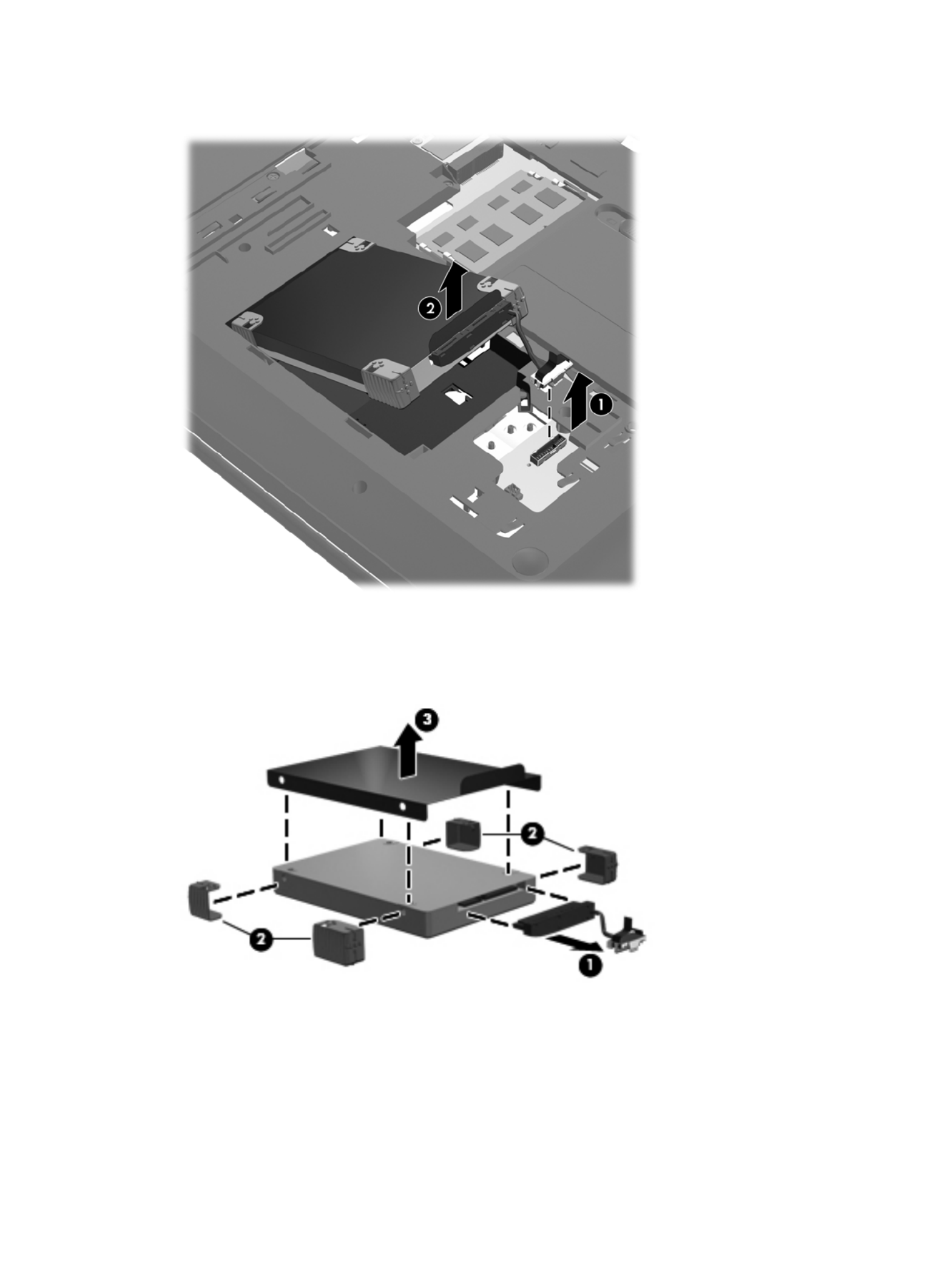
2. Lift the front edge of the hard drive (2) until it rests at an angle.
3. Remove the hard drive.
4. If it is necessary to replace the hard drive connector cable (1), the hard drive isolators (2), or the
Mylar shield (3) from the hard drive, remove and replace the components.
Reverse this procedure to reassemble and install the mass storage device.
48 Chapter 4 Removal and replacement procedures

RTC battery
Description Spare part number
RTC battery (includes cable and double-sided tape) 637193-001
Before removing the RTC battery, follow these steps:
1. Shut down the computer. If you are unsure whether the computer is off or in Hibernation, turn
the computer on, and then shut it down through the operating system.
2. Disconnect all external devices connected to the computer.
3. Disconnect the power from the computer by first unplugging the power cord from the AC outlet
and then unplugging the AC adapter from the computer.
4. Remove the battery (see Battery on page 44).
5. Remove the service cover (see Optical drive on page 45).
Remove the RTC battery:
1. Disconnect the RTC battery cable (1) from the system board.
2. Slide the RTC battery (2) out from under the surface of the base enclosure.
3. Remove the RTC battery (3) from the system board. (The RTC battery is attached to the system
board with double-sided tape.)
Reverse this procedure to install the RTC battery.
Component replacement procedures 49

Memory module
Description Spare part number
4-GB (DDR3, 10600, 1333-MHz) 621569-001
2-GB (DDR3, 10600, 1333-MHz) 621565-001
1-GB (DDR3, 10600, 1333-MHz) 639736-001
Before removing a memory module, follow these steps:
1. Shut down the computer. If you are unsure whether the computer is off or in Hibernation, turn
the computer on, and then shut it down through the operating system.
2. Disconnect all external devices connected to the computer.
3. Disconnect the power from the computer by first unplugging the power cord from the AC outlet
and then unplugging the AC adapter from the computer.
4. Remove the battery (see Battery on page 44).
5. Remove the service cover (see Optical drive on page 45).
Remove the memory module:
1. Spread the retaining tabs (1) on each side of the memory module slot to release the memory
module. (The memory module tilts up.)
2. Remove the memory module (2) by pulling it away from the slot at an angle.
Reverse this procedure to install a memory module.
50 Chapter 4 Removal and replacement procedures
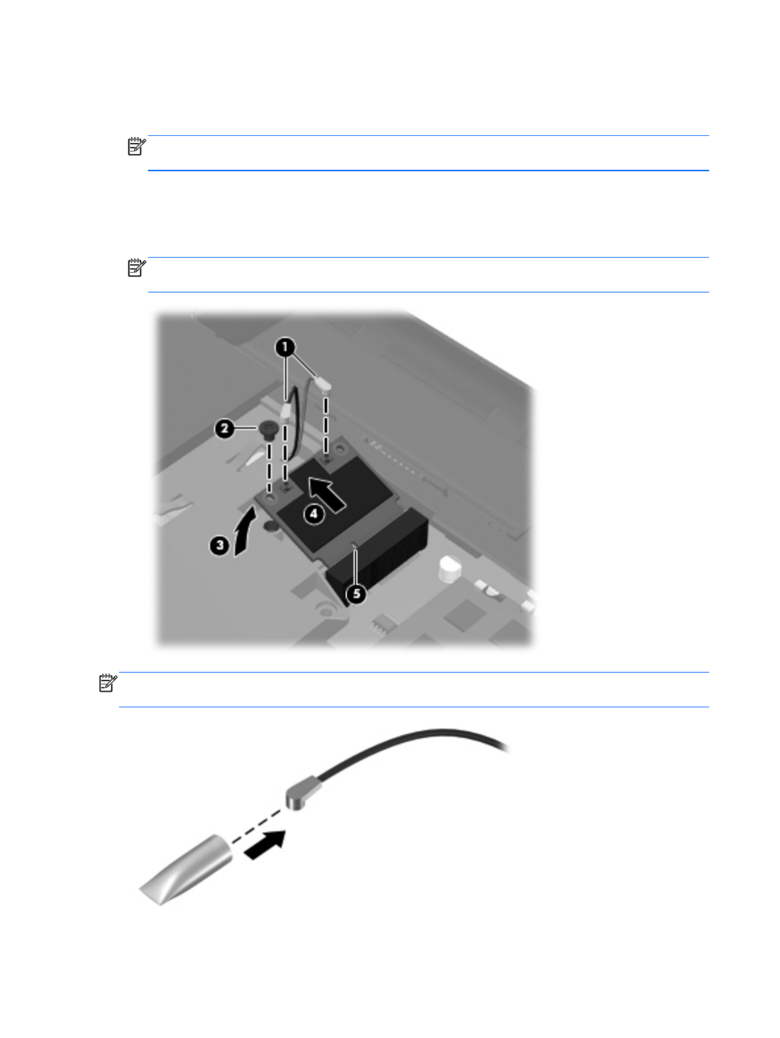
Remove the WLAN module:
1. Disconnect the WLAN antenna cables (1) from the terminals on the WLAN module.
NOTE: The 1/black WLAN antenna cable is connected to the WLAN module 1/Main terminal.
The 2/gray WLAN antenna cable is connected to the WLAN module 2/Aux terminal.
2. Remove the Phillips PM2.5×6.0 screw (2) that secures the WLAN module to the system board.
(The WLAN module tilts up (3).)
3. Remove the WLAN module by pulling the module away from the slot at an angle (4).
NOTE: The WLAN module is designed with a notch (5) to prevent incorrect installation into the
WLAN module socket.
NOTE: If the WLAN antennas are not connected to the terminals on the WLAN module, the protective
sleeves must be installed on the antenna connectors, as shown in the following illustration.
Reverse this procedure to install the WLAN module.
52 Chapter 4 Removal and replacement procedures

Keyboard
NOTE: The keyboard spare part kit includes a keyboard cable.
Description Spare part number Description Spare part number
Keyboard in black finish:
For use in Belgium 640208-A41 For use in the Netherlands 640208-B31
For use in Canada 640208-121 For use in Portugal 640208-131
For use in the Czech Republic 640208-221 For use in Russia 640208-251
For use in Denmark, Finland,
and Norway
640208-DH1 For use in Saudi Arabia 640208-171
For use in France 640208-051 For use in Slovenia 640208-BA1
For use in Germany 640208-041 For use in Spain 640208-071
For use in Greece 640208-DJ1 For use in Switzerland 640208-BG1
For use in Hungary 640208-211 For use in Turkey 640208-141
For use in Israel 640208-BB1 For use in the United Kingdom 640208-031
For use in Italy 640208-061 For use in the United States 640208-001
Keyboard in silver finish:
For use in Belgium 647630-A41 For use in the Netherlands 647630-B31
For use in Canada 647630-121 For use in Portugal 647630-131
For use in the Czech Republic 647630-221 For use in Russia 647630-251
For use in Denmark, Finland,
and Norway
647630-DH1 For use in Saudi Arabia 647630-171
For use in France 647630-051 For use in Slovenia 647630-BA1
For use in Germany 647630-041 For use in Spain 647630-071
For use in Greece 647630-DJ1 For use in Switzerland 647630-BG1
For use in Hungary 647630-211 For use in Turkey 647630-141
For use in Israel 647630-BB1 For use in the United Kingdom 647630-031
For use in Italy 647630-061 For use in the United States 647630-001
Before removing the keyboard, follow these steps:
1. Shut down the computer. If you are unsure whether the computer is off or in Hibernation, turn
the computer on, and then shut it down through the operating system.
2. Disconnect all external devices connected to the computer.
3. Disconnect the power from the computer by first unplugging the power cord from the AC outlet
and then unplugging the AC adapter from the computer.
Component replacement procedures 53

4. Remove the battery (see Battery on page 44).
5. Remove the service cover (see Optical drive on page 45).
Remove the keyboard:
1. Remove the Phillips PM2.5×7.0 screw that secures the keyboard to the computer.
2. Rest the computer on its left side.
3. Open the computer.
54 Chapter 4 Removal and replacement procedures

4. Insert a screw driver or similar thin tool into the keyboard screw hole, and then press on the back
of the keyboard until the keyboard disengages from the computer.
5. Turn the computer right-side up with the front toward you.
6. Lift the rear edge of the keyboard, and then swing the keyboard up and forward until it rests
upside down on the palm rest.
Component replacement procedures 55

7. Release the zero insertion force (ZIF) connector (1) to which the keyboard cable is attached, and
then disconnect the keyboard cable (2) from the system board.
8. Remove the keyboard.
Reverse this procedure to install the keyboard.
56 Chapter 4 Removal and replacement procedures

3. Remove the 12 Phillips PM2.5×7.0 screws that secure the top cover to the computer.
4. Remove the two Phillips PM2.5×7.0 screws (1) in the hard drive bay and the three Phillips
PM2.5×6.0 screws (2) in the battery bay that secure the top cover to the computer.
5. Turn the computer right-side up, with the front toward you.
6. Open the computer.
7. Release the ZIF connectors to which the following cables are attached, and then disconnect the
cables from the system board:
●Power button board cable (1) (included with the power button board spare part kit, spare
part number 640212-001)
●TouchPad cable (2) (included in the Cable Kit, spare part number 640206-001)
●TouchPad button board cable (3) (included with the TouchPad button board spare part kit,
spare part number 640214-001)
58 Chapter 4 Removal and replacement procedures

8. Remove the Phillips PM2.5×6.0 screw (1) that secures the top cover to the computer.
9. Lift the rear edge of the top cover (2) until the left and right sides disengage from the
base enclosure.
10. Remove the top cover (3).
Reverse this procedure to install the top cover.
Component replacement procedures 59

Power button board
Description Spare part number
Power button board (includes cable) 640212-001
Before removing the power button board, follow these steps:
1. Shut down the computer. If you are unsure whether the computer is off or in Hibernation, turn
the computer on, and then shut it down through the operating system.
2. Disconnect all external devices connected to the computer.
3. Disconnect the power from the computer by first unplugging the power cord from the AC outlet
and then unplugging the AC adapter from the computer.
4. Remove the battery (see Battery on page 44), and then remove the following components:
●Optical drive (see Optical drive on page 45)
●Hard drive (see Hard drive on page 47)
●Keyboard (see Keyboard on page 53)
●Top cover (see Top cover on page 57)
Remove the power button board:
1. Turn the top cover upside down, with the front toward you.
2. Release the power button board cable from the clip (1) built into the top cover.
3. Remove the Phillips PM2.0×4.0 screw (2) that secures the power button board to the top cover.
4. Lift the right side of the power button board (3) until it rests at an angle.
60 Chapter 4 Removal and replacement procedures

5. Remove the power button board and cable by sliding the board up and to the right at an
angle (4).
Reverse this procedure to install the power button board and cable.
Component replacement procedures 61

TouchPad button board
Description Spare part number
TouchPad button board (includes cable) 640214-001
Before removing the TouchPad button board, follow these steps:
1. Shut down the computer. If you are unsure whether the computer is off or in Hibernation, turn
the computer on, and then shut it down through the operating system.
2. Disconnect all external devices connected to the computer.
3. Disconnect the power from the computer by first unplugging the power cord from the AC outlet
and then unplugging the AC adapter from the computer.
4. Remove the battery (see Battery on page 44), and then remove the following components:
●Optical drive (see Optical drive on page 45)
●Hard drive (see Hard drive on page 47)
●Keyboard (see Keyboard on page 53)
●Top cover (see Top cover on page 57)
Remove the TouchPad button board and cable:
1. Turn the top cover upside down, with the front toward you.
2. Release the TouchPad board cable (1) (2) and the TouchPad button board cable from the
clips (3) built into the top cover.
3. Release the ZIF connector to which the TouchPad LED board cable is connected, and then
disconnect the TouchPad LED board cable (4) from the TouchPad button board.
4. Remove the Phillips PM2.0×4.0 screw (5) that secures the TouchPad button board to the
top cover.
62 Chapter 4 Removal and replacement procedures

5. Lift the rear edge of the TouchPad button board (6) until it is released from the clips built into the
top cover.
6. Remove the TouchPad button board and cable.
Reverse this procedure to install the TouchPad button board and cable.
TouchPad LED board
Description Spare part number
TouchPad LED board (includes cable) 640213-001
Before removing the TouchPad LED board, follow these steps:
1. Shut down the computer. If you are unsure whether the computer is off or in Hibernation, turn
the computer on, and then shut it down through the operating system.
2. Disconnect all external devices connected to the computer.
3. Disconnect the power from the computer by first unplugging the power cord from the AC outlet
and then unplugging the AC adapter from the computer.
4. Remove the battery (see Battery on page 44), and then remove the following components:
●Optical drive (see Optical drive on page 45)
●Hard drive (see Hard drive on page 47)
●Keyboard (see Keyboard on page 53)
●Top cover (see Top cover on page 57)
Component replacement procedures 63

Remove the TouchPad LED board and cable:
1. Turn the top cover upside down, with the front toward you.
2. Release the ZIF connector (1) to which the TouchPad LED board cable is connected, and then
disconnect the TouchPad LED board cable (2) from the TouchPad button board.
3. Release the TouchPad LED board cable from the clip (3) built into the top cover.
4. Detach the TouchPad LED board from the top cover. (The TouchPad LED board is attached to(4)
the top cover with double-sided tape.)
5. Remove the TouchPad LED board and cable.
Reverse this procedure to install the TouchPad LED board and cable.
64 Chapter 4 Removal and replacement procedures

Bluetooth module
NOTE: This section applies only to computer models equipped with an Intel processor.
Description Spare part number
Bluetooth module
NOTE: The Bluetooth module spare part kit does not include a Bluetooth module cable.
The Bluetooth module cable is available using spare part number 602538-001.
537921-001
Before removing the Bluetooth module and cable, follow these steps:
1. Shut down the computer. If you are unsure whether the computer is off or in Hibernation, turn
the computer on, and then shut it down through the operating system.
2. Disconnect all external devices connected to the computer.
3. Disconnect the power from the computer by first unplugging the power cord from the AC outlet
and then unplugging the AC adapter from the computer.
4. Remove the battery (see Battery on page 44), and then remove the following components:
●Optical drive (see Optical drive on page 45)
●Hard drive (see Hard drive on page 47)
●Keyboard (see Keyboard on page 53)
●Top cover (see Top cover on page 57)
Remove the Bluetooth module and cable:
1. Disconnect the Bluetooth module cable (1) from the system board.
Component replacement procedures 65
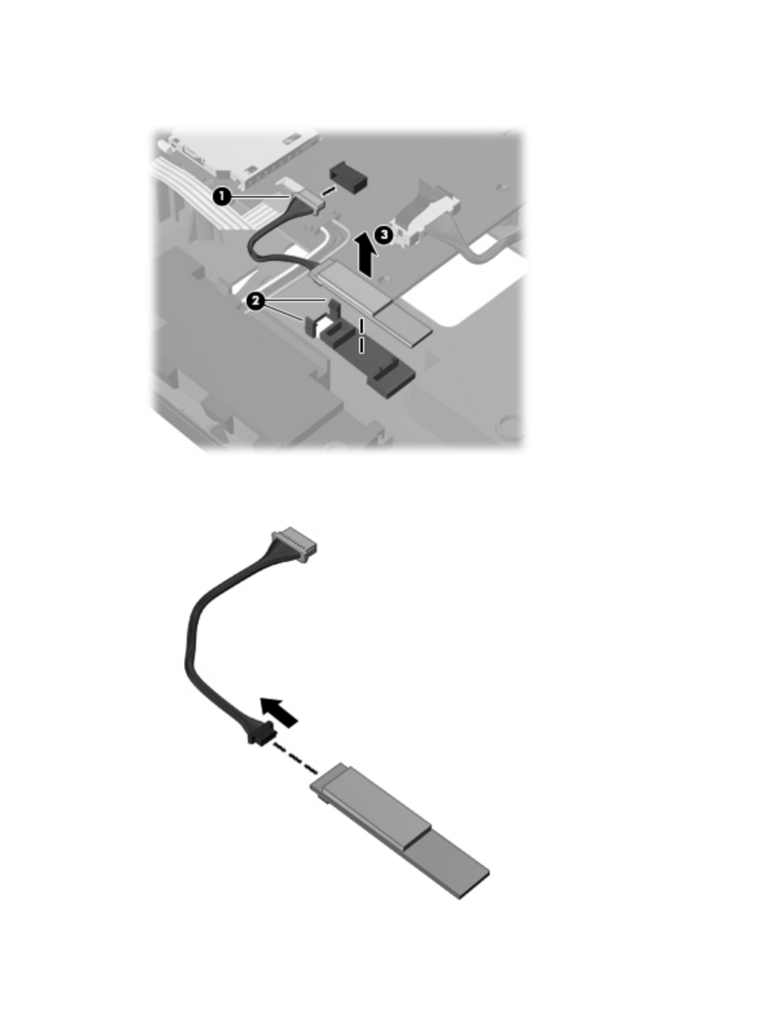
2. Release the clips (2) built into the base enclosure that secure the Bluetooth module, and then
remove the module (3) from the clips.
3. If it is necessary to replace the Bluetooth module cable, disconnect the cable from the Bluetooth
module and replace it.
66 Chapter 4 Removal and replacement procedures

Reverse this procedure to install the Bluetooth module and cable.
Speakers
Description Spare part number
Speaker Kit (includes left and right speakers and cable) 641396-001
Before removing the speakers, follow these steps:
1. Shut down the computer. If you are unsure whether the computer is off or in Hibernation, turn
the computer on, and then shut it down through the operating system.
2. Disconnect all external devices connected to the computer.
3. Disconnect the power from the computer by first unplugging the power cord from the AC outlet
and then unplugging the AC adapter from the computer.
4. Remove the battery (see Battery on page 44), and then remove the following components:
●Optical drive (see Optical drive on page 45)
●Hard drive (see Hard drive on page 47)
●Keyboard (see Keyboard on page 53)
●Top cover (see Top cover on page 57)
Remove the TouchPad LED board and cable:
1. Disconnect the speaker cable (1) from the system board.
2. Remove the speakers (2).
Component replacement procedures 67

Reverse this procedure to install the speakers.
LED board
Description Spare part number
LED board 640215-001
Before removing the LED board, follow these steps:
1. Shut down the computer. If you are unsure whether the computer is off or in Hibernation, turn
the computer on, and then shut it down through the operating system.
2. Disconnect all external devices connected to the computer.
3. Disconnect the power from the computer by first unplugging the power cord from the AC outlet
and then unplugging the AC adapter from the computer.
4. Remove the battery (see Battery on page 44), and then remove the following components:
●Optical drive (see Optical drive on page 45)
●Hard drive (see Hard drive on page 47)
●Keyboard (see Keyboard on page 53)
●Top cover (see Top cover on page 57)
Remove the LED board:
1. Release the ZIF connector (1) to which the LED board cable is connected, and then disconnect the
LED board cable (2) from the system board.
2. Release the clips (3) built into the base enclosure that secure the LED board.
3. Lift the right edge of the LED board (4) to release it from clips built into the base enclosure.
68 Chapter 4 Removal and replacement procedures
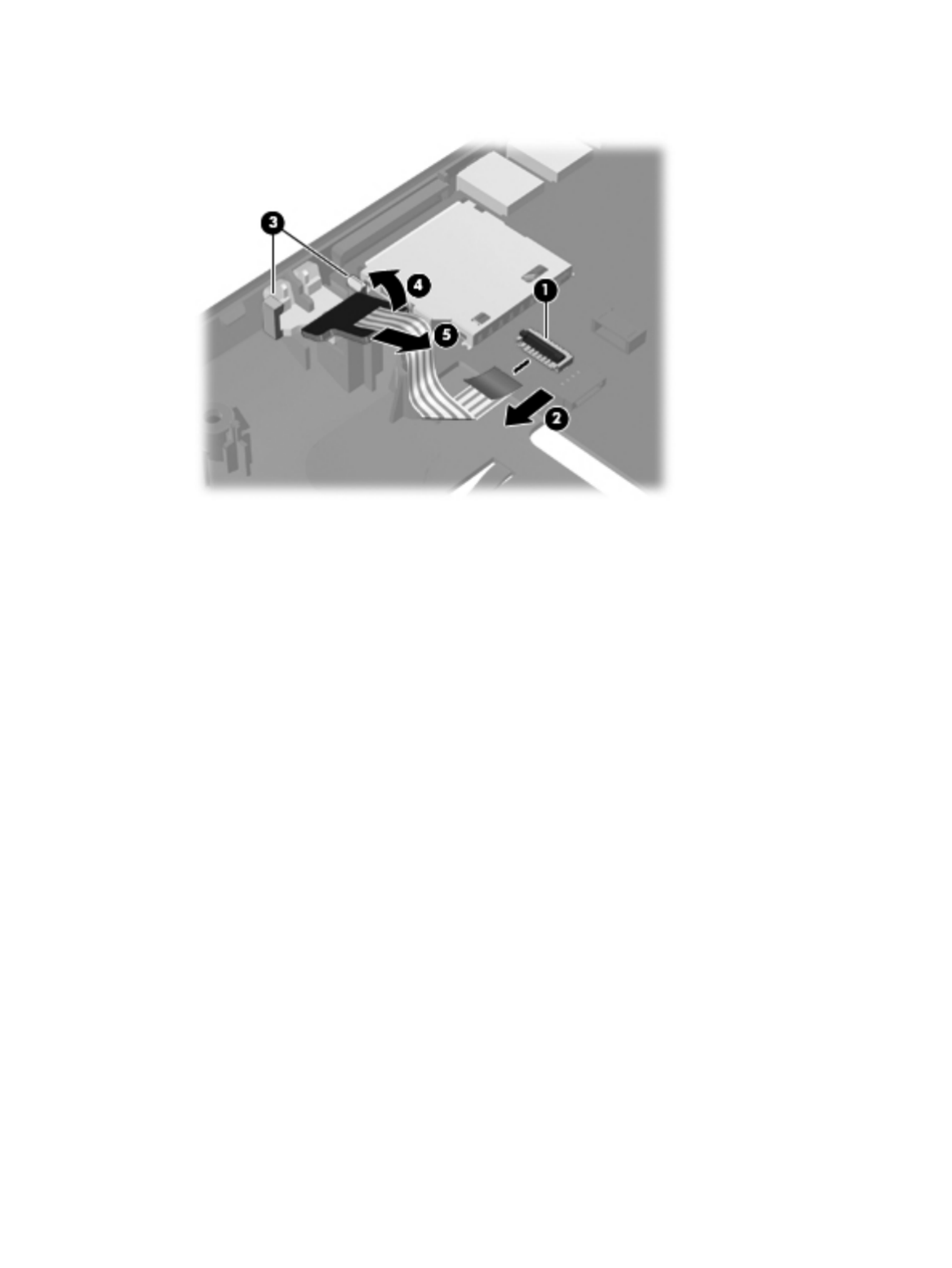
4. Remove the LED board and cable by sliding the board (5) up and to the right at an angle.
Reverse this procedure to install the LED board and cable.
Component replacement procedures 69

USB board
Description Spare part number
USB board (includes cable) 640211-001
Before removing the USB board, follow these steps:
1. Shut down the computer. If you are unsure whether the computer is off or in Hibernation, turn
the computer on, and then shut it down through the operating system.
2. Disconnect all external devices connected to the computer.
3. Disconnect the power from the computer by first unplugging the power cord from the AC outlet
and then unplugging the AC adapter from the computer.
4. Remove the battery (see Battery on page 44), and then remove the following components:
●Optical drive (see Optical drive on page 45)
●Hard drive (see Hard drive on page 47)
●Keyboard (see Keyboard on page 53)
●Top cover (see Top cover on page 57)
Remove the USB board:
1. Release the ZIF connector (1) to which the USB board cable is connected, and then disconnect the
USB board cable (2) from the system board.
2. Release the clip (3) built into the base enclosure that secures the USB board to the base enclosure.
70 Chapter 4 Removal and replacement procedures

3. Remove the USB board (4) and cable.
Reverse this procedure to install the USB board.
Power connector cable
Description Spare part number
Power connector cable 641394-001
Before removing the power connector cable, follow these steps:
1. Shut down the computer. If you are unsure whether the computer is off or in Hibernation, turn
the computer on, and then shut it down through the operating system.
2. Disconnect all external devices connected to the computer.
3. Disconnect the power from the computer by first unplugging the power cord from the AC outlet
and then unplugging the AC adapter from the computer.
4. Remove the battery (see Battery on page 44), and then remove the following components:
●Optical drive (see Optical drive on page 45)
●Hard drive (see Hard drive on page 47)
●Keyboard (see Keyboard on page 53)
●Top cover (see Top cover on page 57)
●USB board (see USB board on page 70)
Component replacement procedures 71
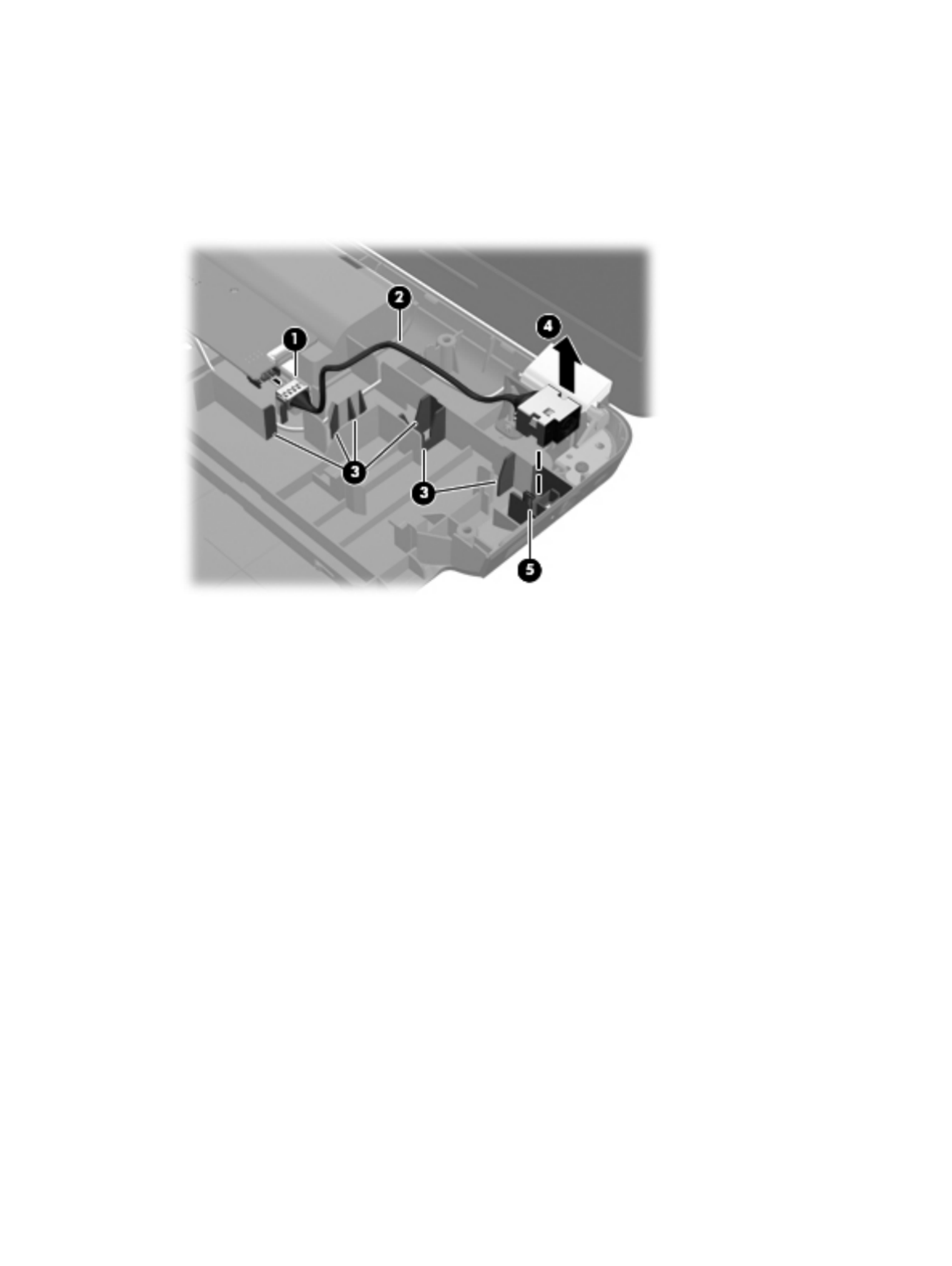
Remove the power connector cable:
1. Disconnect the power connector cable (1) from the system board.
2. Release the power connector cable (2) from the clips (3) built into the base enclosure.
3. Remove the power connector (4) from the clip (5) built into the base enclosure.
Reverse this procedure to install the power connector cable.
72 Chapter 4 Removal and replacement procedures

System board
NOTE: The system board spare part kit includes replacement thermal material. Replacement
thermal material is also available in the Thermal Material Kit, spare part number 634433-001.
Description Spare part number
For use only with computer models equipped with an AMD processor:
For use only with computer models equipped with a graphics subsystem with 1024-MB of discrete
video memory
638855-001
For use only with computer models equipped with a graphics subsystem with 512-MB of discrete
video memory
638854-001
For use only with computer models equipped with a graphics subsystem with UMA video memory 638856-001
For use only with computer models equipped with an Intel processor:
For use only with computer models equipped with an HM65 chipset and a graphics subsystem with
1024-MB of discrete video memory
636375-001
For use only with computer models equipped with an HM65 chipset and a graphics subsystem with
512-MB of discrete video memory
636374-001
For use only with computer models equipped with an HM55 chipset and a graphics subsystem with
1024-MB of discrete video memory
636372-001
For use only with computer models equipped with an HM55 chipset and a graphics subsystem with
512-MB of discrete video memory
636371-001
For use only with computer models equipped with an HM65 chipset and a graphics subsystem with
UMA video memory
636373-001
For use only with computer models equipped with an HM55 chipset and a graphics subsystem with
UMA video memory
636370-001
Before removing the system board, follow these steps:
1. Shut down the computer. If you are unsure whether the computer is off or in Hibernation, turn
the computer on, and then shut it down through the operating system.
2. Disconnect all external devices connected to the computer.
3. Disconnect the power from the computer by first unplugging the power cord from the AC outlet
and then unplugging the AC adapter from the computer.
4. Remove the battery (see Battery on page 44), and then remove the following components:
●Optical drive (see Optical drive on page 45)
●Hard drive (see Hard drive on page 47)
●RTC battery (see RTC battery on page 49)
●WLAN module (see WLAN module on page 51)
Component replacement procedures 73

●Keyboard (see Keyboard on page 53)
●Top cover (see Top cover on page 57)
When replacing the system board, be sure that the following components are removed from the
defective system board and installed on the replacement system board:
●Memory module (see Memory module on page 50)
●Fan and heat sink (see Fan and heat sink on page 79)
●Processor (see Processor on page 86)
Remove the system board:
1. Disconnect the following cables from the system board:
●LED board cable (1)
●Speaker cable (2)
●Optical drive cable (3)
●Display panel cable (4)
2. Remove the Philllips PM2.5×7.0 screw (5) that secures the system board to the base enclosure.
3. Disconnect the power connector cable (1) from the system board.
74 Chapter 4 Removal and replacement procedures

4. Release the ZIF connector to which the USB board cable is attached, and then disconnect the USB
cable (2) from the system board.
5. Lift the right side of the system board (1) until it rests at an angle.
Component replacement procedures 75

6. Remove the system board (2) by sliding it up and to the right at an angle.
NOTE: System boards for use with computer models equipped with an AMD processor have the
Southbridge chip located on the bottom of the board. A thermal pad is used on the Southbridge
chip (1) and the base enclosure heat sink (2) that services it. The thermal material must be
thoroughly cleaned from the surfaces of the system board and the heat sink attached to the base
enclosure each time the system board is removed. Replacement thermal material is included with
all base enclosure and system board spare part kits.
76 Chapter 4 Removal and replacement procedures

Reverse this procedure to install the system board.
Optical drive cable
NOTE: The optical drive cable is included in the Cable Kit, spare part number 640206-001. The
optical drive cable includes the optical drive connector.
Before removing the optical drive cable, follow these steps:
1. Shut down the computer. If you are unsure whether the computer is off or in Hibernation, turn
the computer on, and then shut it down through the operating system.
2. Disconnect all external devices connected to the computer.
3. Disconnect the power from the computer by first unplugging the power cord from the AC outlet
and then unplugging the AC adapter from the computer.
4. Remove the battery (see Battery on page 44), and then remove the following components:
●Optical drive (see Optical drive on page 45)
●Hard drive (see Hard drive on page 47)
●Keyboard (see Keyboard on page 53)
●Top cover (see Top cover on page 57)
●System board (see System board on page 73)
Remove the optical drive cable:
1. Release the optical drive cable (1) from the clips (2) built into the base enclosure.
Component replacement procedures 77

2. Release the clips (3) built into the base enclosure that secure the optical drive connector, and then
release the connector (4) from the clips.
3. Remove the optical drive connector and cable.
Reverse this procedure to install the optical drive connector and cable.
78 Chapter 4 Removal and replacement procedures

Fan and heat sink
NOTE: The fan and heat sink spare part kits include replacement thermal material. Replacement
thermal material is also available in the Thermal Material Kit, spare part number 634433-001.
Description Spare part number
Fan 639460-001
Heat sink:
For use only with computer models equipped with an AMD processor:
For use only with computer models equipped with a graphics subsystem with discrete video memory 639462-001
For use only with computer models equipped with a graphics subsystem with UMA video memory 639463-001
For use only with computer models equipped with an Intel processor:
For use only with computer models equipped with an HM65 chipset and a graphics subsystem with
discrete video memory
641141-001
For use only with computer models equipped with an HM65 chipset and a graphics subsystem with
UMA video memory
641140-001
For use only with computer models equipped with an HM55 chipset and a graphics subsystem with
discrete video memory
637190-001
For use only with computer models equipped with an HM55 chipset and a graphics subsystem with
UMA video memory
637189-001
NOTE: To properly ventilate the computer, allow at least 7.6 cm (3 in) of clearance on the left side of
the computer. The computer uses an electric fan for ventilation. The fan is controlled by a temperature
sensor and is designed to turn on automatically when high temperature conditions exist. These
conditions are affected by high external temperatures, system power consumption, power
management/battery conservation configurations, battery fast charging, and software requirements.
Exhaust air is displaced through the ventilation grill located on the left side of the computer.
Before removing the fan and heat sink, follow these steps:
1. Shut down the computer. If you are unsure whether the computer is off or in Hibernation, turn
the computer on, and then shut it down through the operating system.
2. Disconnect all external devices connected to the computer.
3. Disconnect the power from the computer by first unplugging the power cord from the AC outlet
and then unplugging the AC adapter from the computer.
4. Remove the battery (see Battery on page 44), and then remove the following components:
●Optical drive (see Optical drive on page 45)
●Hard drive (see Hard drive on page 47)
●WLAN module (see WLAN module on page 51)
●Keyboard (see Keyboard on page 53)
Component replacement procedures 79

●Top cover (see Top cover on page 57)
●System board (see System board on page 73)
Remove the fan and heat sink:
1. Turn the system board upside down, with the fan toward you.
NOTE: Steps 2 through 5 apply only to computer models equipped with a graphics subsystem
with discrete memory. See steps 6 through 8 for fan and heat sink removal information for
computer models equipped with a graphics subsystem with UMA memory.
2. Disconnect the fan cable (1) from the system board.
3. Loosen the captive screws (2) that secure the fan and heat sink to the system board. (Computer
models equipped with an AMD processor have three captive screws. Computer models equipped
with an Intel processor have four captive screws.)
4. Remove the three Phillips PM2.5×6.0 screws (3) that secure the fan and heat sink to the
system board.
NOTE: Due to the adhesive quality of the thermal material located between the heat sink and
system board components, it may be necessary to move the heat sink from side to side to
detach it.
80 Chapter 4 Removal and replacement procedures
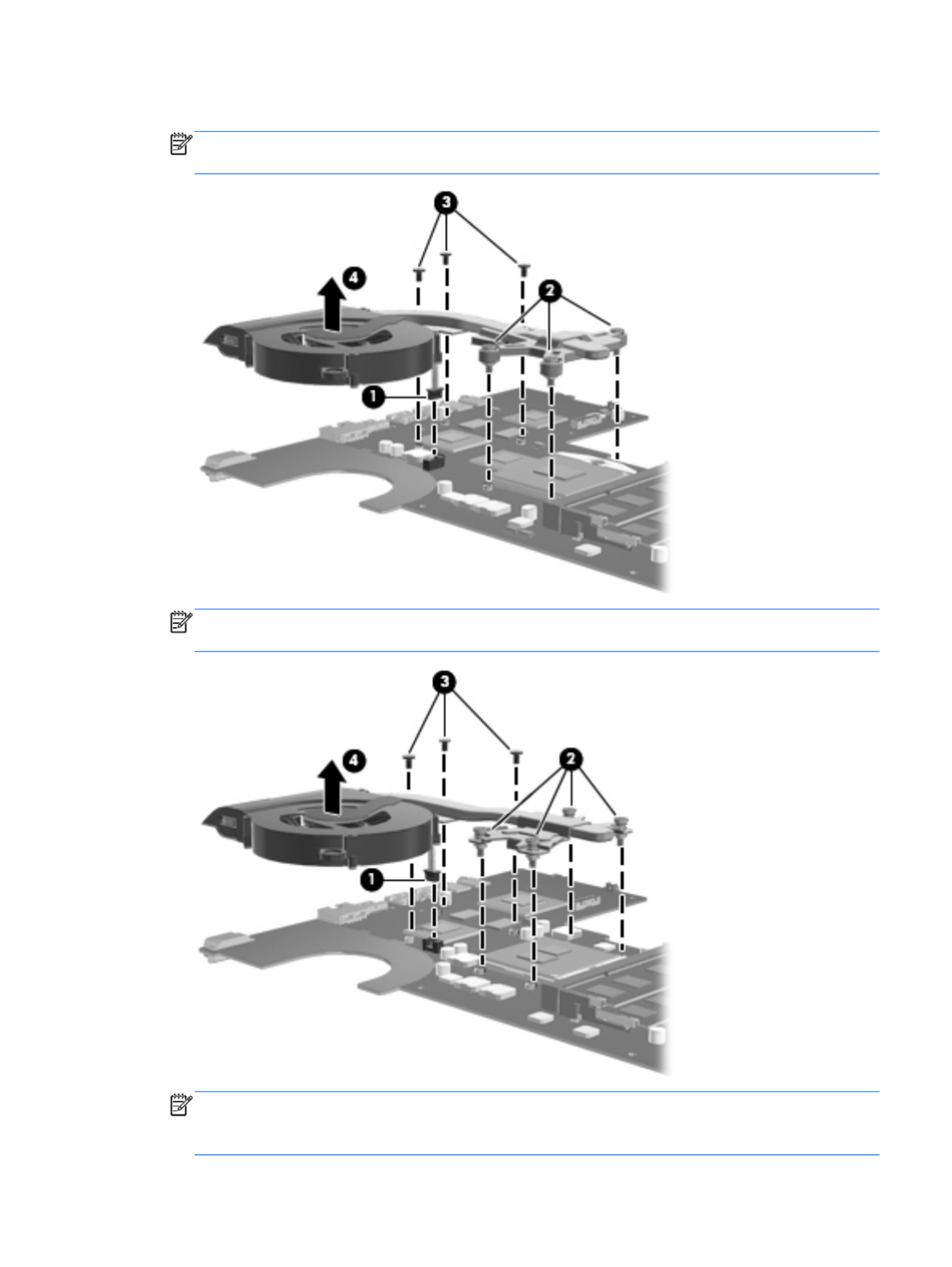
5. Remove the fan and heat sink (4).
NOTE: The following illustration shows the fan and heat sink being removed from a computer
model equipped with an AMD processor and a graphics subsystem with discrete memory.
NOTE: The following illustration shows the fan and heat sink being removed from a computer
model equipped with an Intel processor and a graphics subsystem with discrete memory.
NOTE: Steps 6 through 8 apply only to computer models equipped with a graphics subsystem
with UMA memory. See steps 2 through 5 for fan and heat sink removal information for computer
models equipped with a graphics subsystem with discrete memory.
Component replacement procedures 81

6. Disconnect the fan cable (1) from the system board.
7. Loosen the captive screws (2) that secure the fan and heat sink to the system board. (Computer
models equipped with an AMD processor have three captive screws. Computer models equipped
with an Intel processor have four captive screws.)
NOTE: Due to the adhesive quality of the thermal material located between the heat sink and
system board components, it may be necessary to move the heat sink from side to side to
detach it.
8. Remove the fan and heat sink (3).
NOTE: The following illustration shows the fan and heat sink removal process on a computer
model equipped with an AMD processor and a graphics subsystem with UMA memory.
NOTE: The following illustration shows the fan and heat sink removal process on a computer
model equipped with an Intel processor and a graphics subsystem with UMA memory.
82 Chapter 4 Removal and replacement procedures

NOTE: The thermal material must be thoroughly cleaned from the surfaces of the heat sink and
the system board components each time the heat sink is removed. Replacement thermal material is
included with the base enclosure, fan, heat sink, processor, and system board spare part kits.
Replacement thermal material is also available in the Thermal Material Kit, spare part number
634433-001.
NOTE: The following illustration shows the replacement thermal material locations on a
computer model equipped with an AMD processor and a graphics subsystem with
discrete memory.
●Thermal paste is used on the processor (1) and the heat sink section (2) that services it
●A thermal pad is used on the Northbridge chip (3) and the heat sink section (4) that
services it
●A thermal pad is used on the graphics subsystem chip (5) and the heat sink section (6) that
services it
NOTE: The following illustration shows the replacement thermal material locations on a
computer model equipped with an AMD processor and a graphics subsystem with UMA memory.
●Thermal paste is used on the processor (1) and the heat sink section (2) that services it
●A thermal pad is used on the Northbridge chip (3) and the heat sink section (4) that
services it
Component replacement procedures 83

9. If it is necessary to replace the fan:
a. Remove the two Phillips PM2.0×3.0 screws (1) that secure the fan to the heat sink.
b. Release the two clips (2) that secure the fan to the heat sink.
c. Remove the fan (3) from the heat sink.
Reverse this procedure to reassemble and install the fan and heat sink.
Component replacement procedures 85

Processor
NOTE: The processor spare part kit includes replacement thermal material. Replacement
thermal material is also available in the Thermal Material Kit, spare part number 634433-001.
Description Spare part number
AMD Athlon II P360 2.30-GHz processor (1.0-MB L2 cache, 1066-MHz, 3.2GT/sec, dual core,
25 W)
636635-001
AMD Athlon II P340 2.20-GHz processor (1.0-MB L2 cache, 1066-MHz, 3.2GT/sec, dual core,
25 W)
616343-001
AMD Phenom II N870 2.30-GHz processor (1.5-MB L2 cache, 1333-MHz, 3.6GT/sec, triple core,
35 W)
635495-001
AMD Phenom II N970 2.20-GHz processor (2.0-MB L2 cache, 1333-MHz, 3.6GT/sec, quad core,
35 W)
635496-001
AMD Phenom II P860 2.00-GHz processor (1.5-MB L2 cache, 1333-MHz, 3.6GT/sec, triple core,
35 W)
634688-001
AMD Phenom II N660 3.00-GHz processor (2.0-MB L2 cache, 1333-MHz, 3.6GT/sec, dual core,
35 W)
635494-001
AMD Phenom II N850 2.20-GHz processor (1.5-MB L2 cache, 1333-MHz, 3.6GT/sec, triple core,
35 W)
616345-001
AMD Phenom II P650 2.60-GHz processor (2.0-MB L2 cache, 1066-MHz, 3.6GT/sec, triple core,
25 W)
634687-001
AMD Phenom II P960 1.80-GHz processor (2.0-MB L2 cache, 1066-MHz, 3.6GT/sec, quad core,
25 W)
634689-001
AMD Turion II P560 2.50-GHz processor (2.0-MB L2 cache, 1066-MHz, 3.6GT/sec, dual core,
25 W)
634691-001
AMD V160 2.40-GHz processor (512-KB L2 cache, 1066-MHz 3.2-GT/sec, single core, 25 W) 616333-001
AMD V140 2.30-GHz processor (512-KB L2 cache, 1066-MHz 3.2-GT/sec, single core, 25 W) 636634-001
Intel Core i3-2310M 2.10-GHz processor (3.0-MB L3 cache, dual core, 35 W) 638037-001
Intel Core i3-380M 2.53-GHz processor (3.0-MB L3 cache, dual core, 35 W) 625823-001
Intel Core i3-390M 2.66-GHz processor (3.0-MB L3 cache, dual core, 35 W) 634692-001
Intel Core i5-2410M 2.30-GHz (SC turbo up to 2.90-GHz) processor (3.0-MB L3 cache, dual core,
35 W)
638039-001
Intel Core i5-2520M 2.50-GHz (SC turbo up to 3.20-GHz) processor (3.0-MB L3 cache, dual core,
35 W)
631253-001
Intel Core i5-2540M 2.60-GHz (SC turbo up to 3.30-GHz) processor (3.0-MB L3 cache, dual core,
35 W)
631255-001
Intel Core i5-480M 2.66-GHz (SC turbo up to 2.93-GHz) processor (3.0-MB L3 cache, dual core,
35 W)
634693-001
Intel Core i7-2620M 2.70-GHz (SC turbo up to 3.40-GHz) processor (4.0-MB L3 cache, dual core,
35 W)
631252-001
86 Chapter 4 Removal and replacement procedures

Description Spare part number
Intel Pentium P6200 2.13-GHz processor (3.0-MB L3 cache, dual core, 35 W) 625831-001
Intel Pentium P6300 2.26-GHz processor (3.0-MB L3 cache, dual core, 35 W) 635500-001
Before removing the processor, follow these steps:
1. Shut down the computer. If you are unsure whether the computer is off or in Hibernation, turn
the computer on, and then shut it down through the operating system.
2. Disconnect all external devices connected to the computer.
3. Disconnect the power from the computer by first unplugging the power cord from the AC outlet
and then unplugging the AC adapter from the computer.
4. Remove the battery (see Battery on page 44), and then remove the following components:
●Optical drive (see Optical drive on page 45)
●Hard drive (see Hard drive on page 47)
●WLAN module (see WLAN module on page 51)
●Keyboard (see Keyboard on page 53)
●Top cover (see Top cover on page 57)
●System board (see System board on page 73)
●Fan and heat sink (see Fan and heat sink on page 79)
Remove the processor:
1. Use a flat-bladed screw driver (1) to turn the processor locking screw one-half turn
counterclockwise (2), until you hear a click.
Component replacement procedures 87

Remove the display assembly:
1. Disconnect the display panel cable (1) from the system board.
2. Release the wireless antenna cables (2) from the clips and the opening in the base enclosure.
CAUTION: Support the display assembly when removing the following screws. Failure to
support the display assembly can result in damage to the display assembly and other
computer components.
3. Remove the three Phillips PM2.5×6.0 screws (3) that secure the display assembly to the computer.
4. Remove the display assembly (4).
90 Chapter 4 Removal and replacement procedures
Termékspecifikációk
| Márka: | HP |
| Kategória: | laptop |
| Modell: | g7-2235ew |
Szüksége van segítségre?
Ha segítségre van szüksége HP g7-2235ew, tegyen fel kérdést alább, és más felhasználók válaszolnak Önnek
Útmutatók laptop HP

20 Március 2025
13 Január 2025
12 Január 2025
11 Január 2025
11 Január 2025
11 Január 2025
28 December 2024
28 December 2024
28 December 2024
22 December 2024
Útmutatók laptop
- laptop Samsung
- laptop Sony
- laptop Fujitsu
- laptop Acer
- laptop LG
- laptop Oregon Scientific
- laptop Panasonic
- laptop Lenovo
- laptop Toshiba
- laptop Hyundai
- laptop Apple
- laptop Fellowes
- laptop Medion
- laptop Zebra
- laptop Xiaomi
- laptop Dell
- laptop Gigabyte
- laptop Tripp Lite
- laptop Prixton
- laptop Thomson
- laptop Huawei
- laptop Microsoft
- laptop Asus
- laptop PEAQ
- laptop Haier
- laptop Viewsonic
- laptop Denver
- laptop MSI
- laptop Honor
- laptop SPC
- laptop ADATA
- laptop Kogan
- laptop Razer
- laptop Jay-Tech
- laptop Pyle
- laptop Schneider
- laptop Micromax
- laptop NEC
- laptop Siig
- laptop GoClever
- laptop Getac
- laptop ECS
- laptop Packard Bell
- laptop TechBite
- laptop Alienware
- laptop Airis
- laptop Lexibook
- laptop Emachines
- laptop Trekstor
- laptop Hähnel
- laptop Sylvania
- laptop Coby
- laptop Evga
- laptop Ricatech
- laptop Mpman
- laptop Vizio
- laptop Targa
- laptop Ematic
- laptop Hannspree
- laptop XPG
- laptop Inovia
- laptop Odys
- laptop Ergotron
- laptop Ibm
- laptop Atdec
- laptop Compaq
- laptop Hercules
- laptop Vulcan
- laptop System76
- laptop General Dynamics Itronix
- laptop CTL
- laptop Everex
- laptop Olidata
- laptop Dynabook
- laptop Hamilton Buhl
- laptop AORUS
- laptop Humanscale
- laptop Aplic
- laptop Schenker
Legújabb útmutatók laptop

3 Április 2025

28 Március 2025

28 Március 2025
27 Március 2025

18 Március 2025
16 Január 2025
13 Január 2025

13 Január 2025
12 Január 2025
12 Január 2025