Használati útmutató Gigabyte Z890 AORUS ELITE WIFI7 ICE
Olvassa el alább 📖 a magyar nyelvű használati útmutatót Gigabyte Z890 AORUS ELITE WIFI7 ICE (47 oldal) a alaplap kategóriában. Ezt az útmutatót 7 ember találta hasznosnak és 2 felhasználó értékelte átlagosan 4.5 csillagra
Oldal 1/47

Z890 AORUS ELITE WIFI7 ICE
(Z890 A ELITE WF7 ICE)
Z890 AORUS ELITE WIFI7
(Z890 A ELITE WIFI7)
User's Manual
Rev. 1004
GIGABYTE will reduce paper use in order to fulll the responsibilities of a global citizen.
Also, to reduce the impacts on global warming, the packaging materials of this product
are recyclable and reusable. GIGABYTE works with you to protect the environment.
For more product details, please visit GIGABYTE's website.

Copyright
© 2024 GIGA-BYTE TECHNOLOGY CO., LTD. All rights reserved.
The trademarks mentioned in this manual are legally registered to their respective owners.
Disclaimer
Information in this manual is protected by copyright laws and is the property of GIGABYTE.
Changes to the specications and features in this manual may be made by GIGABYTE without
prior notice. No part of this manual may be reproduced, copied, translated, transmitted, or
published in any form or by any means without GIGABYTE's prior written permission.
For detailed product information, carefully read the User's Manual.
For quick set-up of the product, refer to the Quick Installation Guide on GIGABYTE's
website.
h g g b m mb m gttps://download. i a yte.co /FileList/Manual/ _ anual_installation- uide_800series.pdf
For product-related information, check on our website at: https://www.gigabyte.com
Identifying Your Motherboard Revision
The revision number on your motherboard looks like this: "REV: X.X." For example, "REV: 1.0"
means the revision of the motherboard is 1.0. Check your motherboard revision before updating
motherboard BIOS, drivers, or when looking for technical information.
Example:

- 3 -
Table of Contents
C apter 1 Product Introduction .......................................................................................4h
1-1 Mot er oard Layout ........................................................................................... 4h b
1-2 Mot er oard Bloc Dia ra .............................................................................. 5h b k g m
1-3 Bo Contents ...................................................................................................... 6x
C apter 2 Hardware Installation .....................................................................................7h
2-1 Installation Precautions ...................................................................................... 7
2-2 Product peci cations ........................................................................................ 8S
2-3 Installin t e CPU and CPU Cooler ................................................................. 12g h
2-4 Installin t e Me ory ....................................................................................... 15g h m
2-5 Installin an E pansion Card ........................................................................... 16g x
2-6 Bac Panel Connectors .................................................................................... 17k
2-7 On oard Buttons and LEDs ............................................................................. 19b
2-8 Internal Connectors .......................................................................................... 21
C apter 3 BIO etup ..................................................................................................35h S S
C apter 4 Installin t e Operatin yste and Drivers ...............................................37h g h g S m
4-1 Operatin yste Installation .......................................................................... 37g S m
4-2 Drivers Installation ............................................................................................ 38
C apter 5 Appendi ......................................................................................................39h x
5-1 Con urin a RAID et .................................................................................... 39g g S
5-2 De u LED Codes ............................................................................................ 40b g
Re ulatory Notices ..................................................................................................... 44g
Contact Us .................................................................................................................. 47

- 4 -
1-1 Motherboard Layout
Chapter 1 Product Introduction
M2_WIFI
U35G_LAN
LGA1851
ATX
AUDIO
DDR5_B1
DDR5_B2
DDR5_A1
DDR5_A2
BAT
Intel® Z890
CLR_CMOS
M_BIOS
CODEC
PCIEX16
PCIEX4_1
PCIEX4_2
FU3C_10G
FU3A_5G
USB
SYS_FAN1
FUSB_2
F_AUDIO
FUSB_1
LED_C
SYS_FAN3
SPI_TPM F_PANEL
CPU_FAN
CPU_OPT
iTE®
Super I/O
12V_2X4_2
12V_2X4_1
USB 2.0 Hub
USB 2.0 Hub
SATA3 5 7
4 6
U3A_10G
Temperature sensor
Realtek®
2.5GbE LAN
RST
SYS_FAN2
QFLED
QF_PLUS
80110
M2Q_SB
80
M2A_CPU
110
80
M2B_CPU
110
80
M2M_SB
110
DP
TBT_40G
U3A_5G
ARGB_V2_2
DB_PORT (Note)
POWER
VGA CPU
BOOT DRAM
RESET
FAN4_PUMP
F_HDMI
ARGB_V2_1
ARGB_V2_3
(Note) For debug code information, please refer to the "Debug LED Codes" pages.
Z890 AORUS ELITE WIFI7 ICE
Z890 AORUS ELITE WIFI7
- 5 -
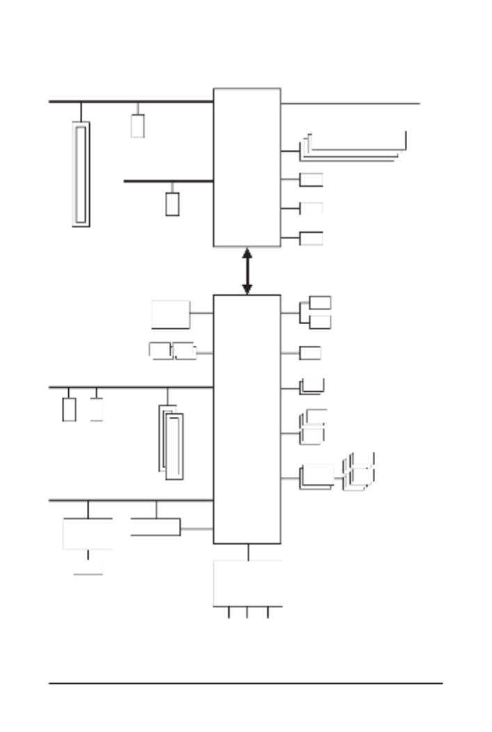
1-2 Motherboard Block Diagram
CPU CLK+/- (80~800 MHz)
DMI 4.0
DDI 1 DisplayPort (Note)
PCI Express 5.0 Bus
1 PCI Express x16
x16
DDI 1 HDMI (Note)
PCI Express 4.0 Bus
1 M.2 Socket 3
(M2B_CPU)
DDR5 6400/5600 MT/s
x4
1 M.2 Socket 3
(M2A_CPU)
x4
LGA1851 CPU
1 Intel® Thunderbolt™ 4 (USB4®
USB Type-C®)
(Note) Actual support may vary by CPU.
4 SATA 6Gb/s
(SATA3 4~7)
eSPI
Bus
SPI
Bus
Line Out
MIC
S/PDIF Out
iTE®
Super I/O
5 USB 3.2 Gen 1
8 USB 2.0/1.1
2 USB 3.2 Gen 2 Type-A
Intel® Z890
BIOS
TPM
USB 2.0
Hub
1 USB Type-C®,
with USB 3.2 Gen 2 support
CODEC
PCI Express 4.0 Bus
2 M.2 Socket 3
(M2M_SB, M2Q_SB)
PCI Express Bus
x4
x1
2 PCI Express x4
LAN
RJ45
x1
Realtek®
2.5GbE LAN
x4 x4
CNVi
M.2 WIFI

- 6 -
1-3 Box Contents
5Z890 AORUS ELITE WIFI7 ICE or Z890 AORUS ELITE WIFI7 motherboard
5User's Manual
5Quick Installation Guide
5One antenna
5Two SATA cables
5One G Connector
5One M.2 thermal pad
5Three packs of M.2 thick/thin rubber pads
* The box contents above are for reference only and the actual items shall depend on the product package you obtain.
The box contents are subject to change without notice.

- 7 -
2-1 Installation Precautions
The motherboard contains numerous delicate electronic circuits and components which can become
damaged as a result of electrostatic discharge (ESD). Prior to installation, carefully read the user's
manual and follow these procedures:
•Prior to installation, make sure the chassis is suitable for the motherboard.
•Prior to installation, do not remove or break motherboard S/N (Serial Number) sticker or
warranty sticker provided by your dealer. These stickers are required for warranty validation.
•Always remove the AC power by unplugging the power cord from the power outlet before
installing or removing the motherboard or other hardware components.
•When connecting hardware components to the internal connectors on the motherboard, make
sure they are connected tightly and securely.
•When handling the motherboard, avoid touching any metal leads or connectors.
•It is best to wear an electrostatic discharge (ESD) wrist strap when handling electronic
components such as a motherboard, CPU or memory. If you do not have an ESD wrist strap,
keep your hands dry and rst touch a metal object to eliminate static electricity.
•Prior to installing the motherboard, please have it on top of an antistatic pad or within an
electrostatic shielding container.
•Before connecting or unplugging the power supply cable from the motherboard, make sure
the power supply has been turned off.
•Before turning on the power, make sure the power supply voltage has been set according to
the local voltage standard.
•Before using the product, please verify that all cables and power connectors of your hardware
components are connected.
•To prevent damage to the motherboard, do not allow screws to come in contact with the
motherboard circuit or its components.
•Make sure there are no leftover screws or metal components placed on the motherboard or
within the computer casing.
•Do not place the computer system on an uneven surface.
•Do not place the computer system in a high-temperature or wet environment.
•Turning on the computer power during the installation process can lead to damage to system
components as well as physical harm to the user.
•If you are uncertain about any installation steps or have a problem related to the use of the
product, please consult a certied computer technician.
•If you use an adapter, extension power cable, or power strip, ensure to consult with its
installation and/or grounding instructions.
Chapter 2 Hardware Installation

- 8 -
2-2 ProductSpecications
CPU LGA1851 socket: Support for Intel® Core™ Ultra Processors
(Go to GIGABYTE's website for the latest CPU support list.)
L3 cache varies with CPU
Chipset Intel® Z890 Express Chipset
Memory Support for DDR5 6400/5600 MT/s memory modules
4 x DDR5 DIMM sockets supporting up to 256 GB (64 GB single DIMM capacity)
of system memory
Dual channel memory architecture
Support for ECC Un-buffered DIMM 1Rx8/2Rx8 memory modules (operate in
non-ECC mode)
Support for non-ECC Un-buffered DIMM 1Rx8/2Rx8/1Rx16 memory modules
Support for Extreme Memory Prole (XMP) memory modules
(The CPU and memory conguration may affect the supported memory types, data
rate (speed), and number of DRAM modules, please refer to "Memory Support
List" on GIGABYTE's website for more information.)
Onboard
Graphics
Integrated Graphics Processor-Intel® HD Graphics support:
- 1 x Intel® Thunderbolt™ 4 connector (USB4® USB Type-C® port),
supporting DisplayPort and Thunderbolt™ video outputs
When a Thunderbolt™ monitor is installed, the maximum resolution
supported is 5120x2880@60 Hz with 24 bpp (single display output).
When a USB4® USB Type-C
® monitor is installed, the maximum
resolution supported is 3840x2160@240 Hz (single display output).
* Because of the limited I/O resources of the PC architecture, the number of
Thunderbolt™ devices that can be used is dependent on the number of the PCI
Express devices being installed. (Refer to Chapter 2-6, "Back Panel Connectors,"
for more information.)
* Support for DisplayPort 2.1 version and HDCP 2.3
- 1 x front HDMI port, supporting a maximum resolution of 1920x1080@30 Hz
* Support for HDMI 1.4 version
- 1 x DisplayPort, supporting a maximum resolution of 4096x2304@60 Hz
* Support for DisplayPort 2.1 version and HDCP 2.3
(Graphics specications may vary depending on CPU support.)
Support for up to triple-display at the same time
Audio Realtek® ALC1220 CODEC
* The back panel line out jack supports DSD audio.
High Denition Audio
2/4/5.1/7.1-channel
* You can change the functionality of an audio jack using the audio software. To congure
7.1-channel audio, access the audio software for audio settings.
Support for S/PDIF Out
LAN Realtek® 2.5GbE LAN chip (2.5 Gbps/1 Gbps/100 Mbps)
- 9 -
Wireless
Communication
Module
MediaTek Wi-Fi 7 MT7925 (PCB rev. 1.0)
- 802.11a, b, g, n, ac, ax, be, supporting 2.4/5/6 GHz carrier frequency bands
- BLUETOOTH 5.4
- Support for 11be 160MHz wireless standard
Realtek® Wi-Fi 7 RTL8922AE (PCB rev. 1.1)
- 802.11a, b, g, n, ac, ax, be, supporting 2.4/5/6 GHz carrier frequency bands
- BLUETOOTH 5.4
- Support for 11be 160MHz wireless standard
(Actual data rate may vary depending on environment and equipment.)
* Wi-Fi 7 features require Windows 11 SV3 to function properly. (There is no support
driver for Windows 10.)
** Wi-Fi 7 channels on 6 GHz band availability depends on individual country's
regulations.
Expansion Slots CPU:
- 1 x PCI Express x16 slot, supporting PCIe 5.0 and running at x16
(PCIEX16)
* The PCIEX16 slot can only support a graphics card or an NVMe SSD. If only one
graphics card is to be installed, be sure to install it in the PCIEX16 slot.
Chipset:
- 2 x PCI Express x16 slots, supporting PCIe 4.0 and running at p9-x4
(PCIEX4_1, PCIEX4_2)
Storage Interface CPU:
- 1 x M.2 connector (Socket 3, M key, type 25110/22110/2580/2280 PCIe 5.0
x4/x2 SSD support) (M2A_CPU)
- 1 x M.2 connector (Socket 3, M key, type 22110/2280 PCIe 4.0 x4/x2 SSD
support) (M2B_CPU)
Chipset:
- 1 x M.2 connector (Socket 3, M key, type 25110/22110/2580/2280 PCIe 4.0
x4/x2 SSD support) (M2Q_SB)
- 1 x M.2 connector (Socket 3, M key, type 22110/2280 SATA and PCIe 4.0 x4
SSD support) (M2M_SB)
- 4 x SATA 6Gb/s connectors
RAID 0, RAID 1, RAID 5, and RAID 10 support for NVMe SSD storage devices
RAID 0, RAID 1, RAID 5, and RAID 10 support for SATA storage devices
USB CPU:
- 1 x USB4® USB Type-C® port on the back panel
Chipset:
- 1 x USB Type-C® port with USB 3.2 Gen 2 support, available through the
internal USB header
- 2 x USB 3.2 Gen 2 Type-A ports (red) on the back panel
- 5 x USB 3.2 Gen 1 ports (3 ports on the back panel, 2 ports available
through the internal USB header)
Chipset+2 USB 2.0 Hubs:
- 8 x USB 2.0/1.1 ports (4 ports on the back panel, 4 ports available through
the internal USB headers)

- 10 -
Internal
Connectors
1 24-pin AT ain power connectorx X m
2 8-pin AT 12 power connectorsx X V
1 CPU fan eaderx h
1 CPU fan/water coolin pu p eaderx g m h
3 syste fan eadersx m h
1 syste fan/water coolin pu p eaderx m g m h
3 addressa le RGB Gen2 LED strip eadersx b h
1 RGB LED strip eaderx h
4 M.2 oc et 3 connectorsx S k
4 ATA 6G /s connectorsx S b
1 front panel eaderx h
1 front panel audio eaderx h
1 U B Type-Cx S ® eader, wit U B 3.2 Gen 2 supporth h S
1 U B 3.2 Gen 1 eaderx S h
2 U B 2.0/1.1 eadersx S h
1 Trusted Platforx m Module header (For the GC-TPM2.0 SPI/GC-TPM2.0 SPI 2.0/
GC-TPM2.0 PI 2 S V module only)
1 HDMI portx (Note)
1 power uttonx b
1 reset uttonx b
1 -Flas Plus uttonx Q h b
1 reset u perx j m
1 Clear CMO u perx S j m
Bac Panel k
Connectors
1 Intelx® T under olth b ™ 4 connector (U B4S® U B Type-CS® port)
2 U B 3.2 Gen 2 Type-A ports (red)x S
3 U B 3.2 Gen 1 portsx S
4 U B 2.0/1.1 portsx S
2 antenna connectors (2T2R)x
1 DisplayPortx (Note)
1 RJ-45 portx
1 optical /PDIF Out connectorx S
2 audio ac sx j k
I/O Controller iTE® I/O Controller C iph
Hardware
Monitor
Volta e detectiong
Te perature detectionm
Fan speed detection
Water coolin ow rate detectiong
Fan fail warning
Fan speed control
* W et er t e fan (pu p) speed control function is supported will depend on t e fan h h h m h
(pu p) you install.m
(Note) Actual support may vary by CPU.
Termékspecifikációk
| Márka: | Gigabyte |
| Kategória: | alaplap |
| Modell: | Z890 AORUS ELITE WIFI7 ICE |
Szüksége van segítségre?
Ha segítségre van szüksége Gigabyte Z890 AORUS ELITE WIFI7 ICE, tegyen fel kérdést alább, és más felhasználók válaszolnak Önnek
Útmutatók alaplap Gigabyte

14 Január 2025
13 Január 2025
12 Január 2025
12 Január 2025
12 Január 2025
9 Január 2025
9 Január 2025
9 Január 2025
9 Január 2025
9 Január 2025
Útmutatók alaplap
- alaplap Sharkoon
- alaplap Asus
- alaplap Supermicro
- alaplap Biostar
- alaplap Asrock
- alaplap MSI
- alaplap NZXT
- alaplap ECS
- alaplap Evga
- alaplap Intel
- alaplap Foxconn
- alaplap Advantech
- alaplap Elitegroup
- alaplap EPoX
Legújabb útmutatók alaplap

9 Április 2025
9 Április 2025
3 Április 2025
3 Április 2025
3 Április 2025
3 Április 2025
2 Április 2025
2 Április 2025

31 Március 2025
27 Március 2025