Használati útmutató Gigabyte R283-Z90
Olvassa el alább 📖 a magyar nyelvű használati útmutatót Gigabyte R283-Z90 (184 oldal) a szerver kategóriában. Ezt az útmutatót 2 ember találta hasznosnak és 2 felhasználó értékelte átlagosan 4.5 csillagra
Oldal 1/184

R283-Z90-AAD1
R283-Z90-AAD2
R283-Z90-AAD3
AMD EPYC™ 9004 Server System - 2U DP 12+4-Bay NVMe/SATA/SAS (AAD1/AAD2)
AMD EPYC™ 9004 Server System - 2U DP 12+2-Bay SATA/SAS (AAD3)
User Manual
Rev. 1.0

Copyright
© 2022 GIGA-BYTE TECHNOLOGY CO., LTD. All rights reserved.
The trademarks mentioned in this manual are legally registered to their respective owners.
Disclaimer
Information in this manual is protected by copyright laws and is the property of GIGABYTE.
Changes to the specications and features in this manual may be made by GIGABYTE without
prior notice. No part of this manual may be reproduced, copied, translated, transmitted, or
published in any form or by any means without GIGABYTE's prior written permission.
Documentation Classications
In order to assist in the use of this product, GIGABYTE provides the following types of documentation:
User Manual: detailed information & steps about the installation, conguration and use of this
product (e.g. motherboard, server barebones), covering hardware and BIOS.
User Guide: detailed information about the installation & use of an add-on hardware or
software component (e.g. BMC rmware, rail-kit) compatible with this product.
Quick Installation Guide: a short guide with visual diagrams that you can reference easily for
installation purposes of this product (e.g. motherboard, server barebones).
Please see the support section of the online product page to check the current availability of these
documents.
For More Information
For related product specications, the latest rmware and software, and other information please visit our website at
http://www.gigabyte.com
For GIGABYTE distributors and resellers, additional sales & marketing materials are available from our reseller
portal: http://reseller.b2b.gigabyte.com
For further technical assistance, please contact your GIGABYTE representative or visit
https://esupport.gigabyte.com/ to create a new support ticket
For any general sales or marketing enquiries, you may also message GIGABYTE server directly by email:
server.grp@gigabyte.com
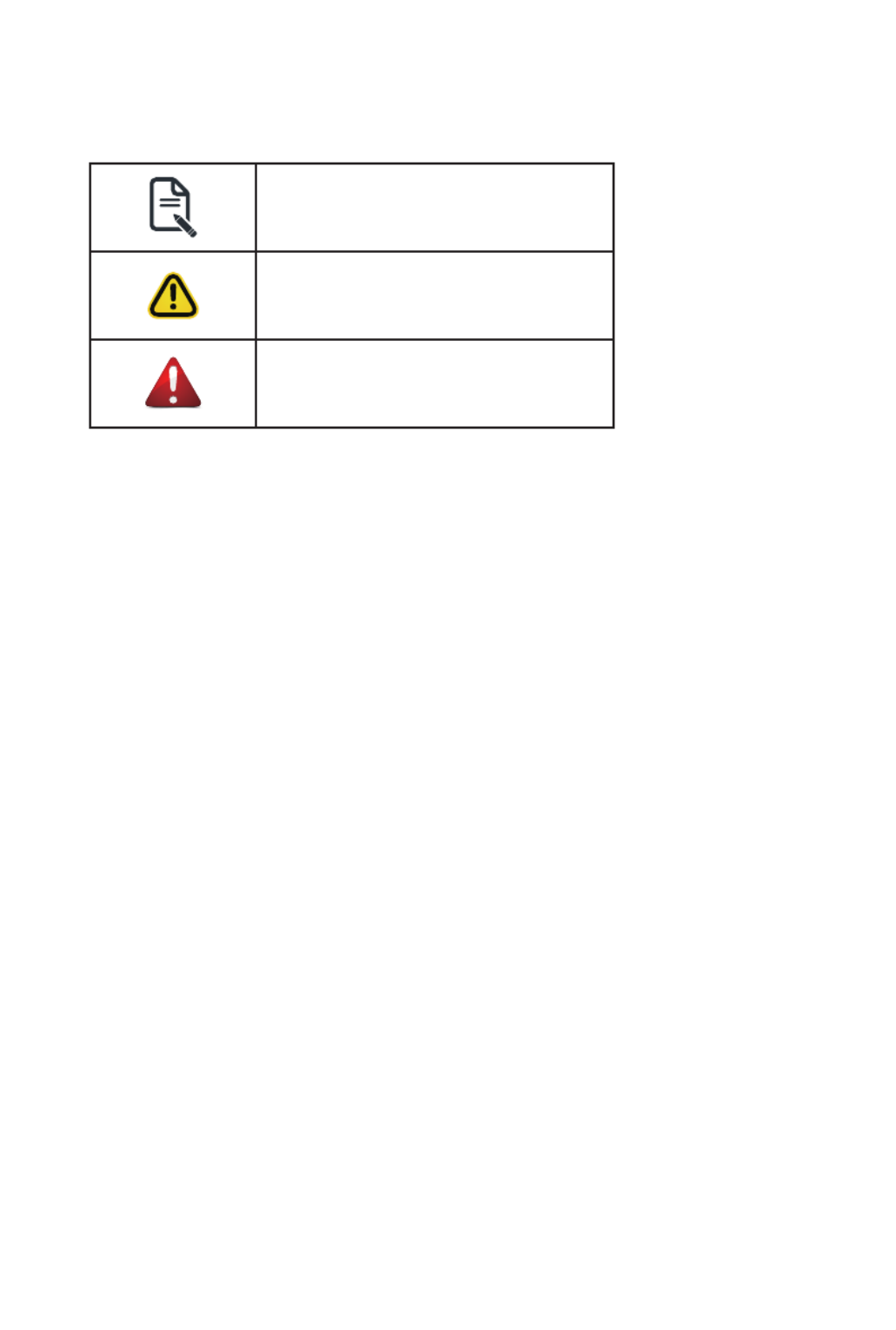
Conventions
The following conventions are used in this user's guide:
NOTE!
Pieces of additional
information related to the current topic.
CAUTION!
Precautionary measures to
avoid possible hardware or software problems.
WARNING!
Alerts to any damage that might
result from doing or not doing specic actions.

Server Warnings and Cautions
Before installing a server, be sure that you understand the following warnings and cautions.
WARNING!
To reduce the risk of electric shock or damage to the equipment:
• Do not disable the power cord grounding plug. The grounding plug is an important safety
feature.
• Plug the power cord into a grounded (earthed) electrical outlet that is easily accessible at all
times.
• Unplug the power cord from the power supply to disconnect power to the equipment.
• Do not route the power cord where it can be walked on or pinched by items placed against it.
Pay particular attention to the plug, electrical outlet, and the point where the cord extends from
the server.
WARNING!
To reduce the risk of personal injury from hot surfaces, allow the drives and the internal
system components to cool before touching them.
WARNING!
This server is equipped with high speed fans. Keep away from hazardous moving fan
blades during servicing.
CAUTION!
• Do not operate the server for long periods with the access panel open or removed. Operat-
ing the server in this manner results in improper airow and improper cooling that can lead to
thermal damage.
• Danger of explosion if battery is incorrectly replaced.
• Replace battery with the same or equivalent type recommended by the manufacturer.
• Dispose of used batteries according to the manufacturer’s instructions.
CAUTION!
Risk of explosion if battery is replaced incorrectly or with an incorrect type. Replace the battery
only with the same or equivalent type recommended by the manufacturer. Dispose of used bat-
teries according to the manufacturer’s instructions.

Electrostatic Discharge (ESD)
CAUTION!
ESD CAN DAMAGE DRIVES, BOARDS, AND OTHER PARTS. WE RECOMMEND THAT YOU
PERFORM ALL PROCEDURES AT AN ESD WORKSTATION. IF ONE IS NOT AVAILABLE,
PROVIDE SOME ESD PROTECTION BY WEARING AN ANTI-STATIC WRIST STRAP AT-
TACHED TO CHASSIS GROUND -- ANY UNPAINTED METAL SURFACE -- ON YOUR SERVER
WHEN HANDLING PARTS.
Always handle boards carefully, they can be extremely sensitive to ESD. Hold boards only by
their edges without touching any components or connectors. After removing a board from its
protective ESD bag or from the system, place the board component side up on a grounded, static
free surface. Use a conductive foam pad if available but not the ESD bag. Do not slide the board
over any surface.
System power on/off: To service components within the server, please ensure the power has
been disconnected.
e.g. Remove the node from the server chassis (to disconnect power) or disconnect the power
from the server chassis.
Make sure the system is removed from the rack before opening the chassis, adding, or removing
any non hot-plug components.
Hazardous conditions, devices and cables: Hazardous electrical conditions may be present
on power, telephone, and communication cables. Turn off the system chassis and disconnect the
cables attached to the system before servicing the chassis. Otherwise, personal injury or equip-
ment damage can result.
Electrostatic discharge (ESD) and ESD protection: ESD can damage drives, boards, and
other parts. We recommend that you perform all procedures in this chapter only at an ESD work-
station. If one is not available, provide some ESD protection by wearing an antistatic wrist strap
attached to chassis ground (any unpainted metal surface on the server) when handling parts.
ESD and handling boards: Always handle boards carefully. They can be extremely sensi-tive to
electrostatic discharge (ESD). Hold boards only by their edges. After removing a board from its
protective wrapper or from the system, place the board component side up on a grounded, static
free surface. Use a conductive foam pad if available but not the board wrapper. Do not slide
board over any surface.

- 7 -
Table of Contents
Chapter 1 Hardware Installation ...................................................................................11
1-1 Installation Precautions .................................................................................. 11
1-2 Product Specications .................................................................................... 12
1-3 System Block Diagram 18 ...................................................................................
1-3-1 R283-Z90-AAD1 .....................................................................................................18
1-3-2 R283-Z90-AAD2 .....................................................................................................19
1-3-3 R283-Z90-AAD3 .....................................................................................................20
Chapter 2 System Appearance .....................................................................................21
2-1 Front View 21 ......................................................................................................
2-2 Rear View 22 .......................................................................................................
2-3 Front Panel LEDs and Buttons 23 .......................................................................
2-4 RoT LEDs 25 .......................................................................................................
2-5 Rear System LAN LEDs 27 .................................................................................
2-6 Power Supply Unit LED 28 ..................................................................................
2-7 Hard Disk Drive LEDs 29 ....................................................................................
Chapter 3 System Hardware Installation 30 ......................................................................
3-1 Removing and Installing the Chassis Cover 31 ..................................................
3-2 Removing and Installing the Hard Disk Drive 32 .................................................
3-3 Removing and Installing the Fan Duct 34 ...........................................................
3-4 Removing and Installing the Heat Sink 35 ..........................................................
3-5 Removing and Installing the CPU 36 ..................................................................
3-6 Removing and Installing Memory 38 ...................................................................
3-6-1 Twelves Channel Memory Conguration ................................................................38
3-6-2 Removing and Installing a Memory Module 39 ...........................................................
3-6-3 Processor and Memory Module Matrix Table 39 .........................................................
3-6-4 Memory Population Table .......................................................................................40
3-7 Removing and Installing the PCIe Card 42 .........................................................
3-8 Installing the Mezzanine Card 44 ........................................................................
3-8-1 Installing the OCP 3.0 Mezzanine Card 44 .................................................................
3-9 Installing the M.2 Device and Heat Sink 45 ........................................................
3-9-1 M.2 device with Heatsink 45 ........................................................................................
3-10 Replacing the Fan Assembly 46 ..........................................................................
3-11 Removing and Installing the Power Supply 47 ....................................................

- 10 -
This page intentionally left blank

- 11 -
Hardware Installation
1-1 Installation Precautions
The motherboard/system contain numerous delicate electronic circuits and components which
can become damaged as a result of electrostatic discharge (ESD). Prior to installation, carefully
read the service guide and follow these procedures:
• Prior to installation, do not remove or break motherboard S/N (Serial Number) sticker or
warranty sticker provided by your dealer. These stickers are required for warranty validation.
• Always remove the AC power by unplugging the power cord from the power outlet before
installing or removing the motherboard or other hardware components.
• When connecting hardware components to the internal connectors on the motherboard,
make sure they are connected tightly and securely.
• When handling the motherboard, avoid touching any metal leads or connectors.
• It is best to wear an electrostatic discharge (ESD) wrist strap when handling electronic
components such as a motherboard, CPU or memory. If you do not have an ESD wrist
strap, keep your hands dry and rst touch a metal object to eliminate static electricity.
•
Prior to installing the motherboard, please have it on top of an antistatic pad or within an
electrostatic shielding container.
• Before unplugging the power supply cable from the motherboard, make sure the power
supply has been turned off.
• Before turning on the power, make sure the power supply voltage has been set according to
the local voltage standard.
• Before using the product, please verify that all cables and power connectors of your
hardware components are connected.
• To prevent damage to the motherboard, do not allow screws to come in contact with the
motherboard circuit or its components.
• Make sure there are no leftover screws or metal components placed on the motherboard or
within the computer casing.
• Do not place the computer system on an uneven surface
.
• Do not place the computer system in a high-temperature environment.
• Turning on the computer power during the installation process can lead to damage to
system components as well as physical harm to the user.
• If you are uncertain about any installation steps or have a problem related to the use of the
product, please consult a certied computer technician.
Chapter 1 Hardware Installation

Hardware Installation
- 12 -
1-2 Product Specications
System
Dimension
2U
438 (W) x 43.5 (H) x 815(D) mm
CPU AMD EPYC™ 9004 series processor family
Dual processors, 5nm technology
Up to 96-core, 192 threads per processor
cTDP up to 400W
Socket
Socket 2 x LGA 6096
Socket SP5
Chipset System on Chip
Memory 24 x DIMM slots
DDR5 memory supported only
12-Channel memory architecture per processor
RDIMM modules up to 128GB supported
3DS RDIMM modules up to 256GB supported
Memory speed: Up to 4800 MHz
LAN 2 x 1GbE LAN ports (1 x Intel® I350-AM2)
Supported NCSI function
1 x 10/100/1000 management LAN
Video Integrated in Aspeed® AST2600
2D Video Graphic Adapter with PCIe bus interface
1920x1200@60Hz 32bpp, DDR4 SDRAM
Storage
(AAD1)
12 x 3.5/ 2.5" Gen4 NVMe/ SATA/ SAS hot-swappable bays
4 x 2.5" SATA/ SAS hot-swappable bays in rear side
NOTE: SAS card is required for SAS devices support
(AAD2) 4 x 3.5/ 2.5" Gen4 NVMe/ SATA/ SAS hot-swappable bays
8 x 3.5/ 2.5" SATA/ SAS hot-swappable bays
4 x 2.5" SATA/ SAS hot-swappable bays in rear side
NOTE: SAS card is required for SAS devices support
(AAD3) 12 x 3.5/ 2.5" SATA/ SAS hot-swappable bays
2 x 2.5" SATA/ SAS hot-swappable bays in rear side
NOTE: SAS card is required for SAS devices support
SAS Depends on SAS Add-on card
NOTE:
We reserve the right to make any changes to the product specications and product-related
information without prior notice.

- 13 -
Hardware Installation
Expansion Slot
(AAD1)
Riser Card CRS101T:
1 x PCIe x16 slot (Gen5 x16), FHHL from CPU_0
Riser Card CRS101Q:
1 x PCIe x16 slot (Gen5 x16), FHHL from CPU_1
Riser Card CRS202M:
1 x PCIe x16 slot (Gen5 x16), FHHL from CPU_0
1 x PCIe x16 slot disabled
1 x OCP 3.0 slot with PCIe Gen5 x16 bandwidth
1 x OCP 3.0 slot disabled
( 1 x from CPU_0 disabled and 1 x from CPU_1)
Supported NCSI function
1 x M.2 slot:
M-key
PCIe Gen3 p13-x4 from CPU_0
Supports 2280/22110 cards
1 x M.2 slot:
M-key
PCIe Gen3 p13-x4 from CPU_1
Supports 2280/22110 cards
1 x M.2 slot:
M-key
- PCIe Gen3 x2 from CPU_1
- Supports 2280/22110 cards

Hardware Installation
- 14 -
Expansion Slot
(AAD2)
Riser Card CRS101T:
1 x PCIe x16 slot (Gen5 x16), FHHL from CPU_0
Riser Card CRS101Q:
1 x PCIe x16 slot (Gen5 x16), FHHL from CPU_1
Riser Card CRS202M:
1 x PCIe x16 slot (Gen5 x16), FHHL from CPU_0
1 x PCIe x16 slot disabled
Riser Card CRS202N:
1 x PCIe x16 slot (Gen5 x16), FHHL from CPU_1
1 x PCIe x16 slot disabled
2 x OCP 3.0 slots with PCIe Gen5 x16 bandwidth
( 1 x from CPU_0 and 1 x from CPU_1)
Supported NCSI function
1 x M.2 slot:
M-key
PCIe Gen3 p14-x4 from CPU_0
Supports 2280/22110 cards
1 x M.2 slot:
M-key
PCIe Gen3 p14-x4 from CPU_1
Supports 2280/22110 cards
1 x M.2 slot:
M-key
PCIe Gen3 x2 from CPU_1
Supports 2280/22110 cards

- 15 -
Hardware Installation
Expansion Slot
(AAD3)
Riser Card CRS101T:
1 x PCIe x16 slot (Gen5 x16), FHHL from CPU_0
Riser Card CRS101Q:
1 x PCIe x16 slot (Gen5 x16), FHHL from CPU_1
Riser Card CRS202M:
1 x PCIe x16 slot (Gen5 x16), FHHL from CPU_0
1 x PCIe x16 slot (Gen5 x8), FHHL from CPU_1
Riser Card CRS202N:
1 x PCIe x16 slot (Gen5 x16), FHHL from CPU_1
1 x PCIe x16 slot (Gen5 x8), FHHL from CPU_1
2 x OCP 3.0 slots with PCIe Gen5 x16 bandwidth
( 1 x from CPU_0 and 1 x from CPU_1)
Supported NCSI function
1 x M.2 slot:
M-key
PCIe Gen3 p15-x4 from CPU_0
Supports 2280/22110 cards
1 x M.2 slot:
M-key
PCIe Gen3 p15-x4 from CPU_1
Supports 2280/22110 cards
1 x M.2 slot:
M-key
PCIe Gen3 x2 from CPU_1
Supports 2280/22110 cards
Internal I/O 3 x M.2 slots
1 x TPM header
2 x OCP 3.0 mezzanine slots

- 16 -
Hardware Installation
Front I/O 2 x USB 3.2 Gen1
1 x Power button with LED
1 x ID button with LED
1 x NMI button
1 x Reset button
2 x LAN activity LEDs
1 x HDD activity LED
1 x System status LED
Rear Panel I/O 2 x USB 3.2 Gen1
1 x Mini-DP
2 x RJ45
1 x MLAN
1 x ID button with LED
Backplane I/O
(AAD1)
Front Side Backplane P/N: 9CBP20C5NR-00
Rear Side Backplane P/N: 9CBP2022NR-00
Speed and bandwidth:
PCIe Gen4 p16-x4 or SATA 6Gb/s or SAS 12Gb/s in front side
SATA 6Gb/s or SAS 12Gb/s in rear side
(AAD2) Front Side Backplane P/N: 9CBP20C5NR-00
Rear Side Backplane P/N: 9CBP2022NR-00
Speed and bandwidth:
PCIe Gen4 p16-x4 or SATA 6Gb/s or SAS 12Gb/s in front side
SATA 6Gb/s or SAS 12Gb/s in rear side
(AAD3) Front Side Backplane P/N: 9CBP20C5NR-00
Rear Side Backplane P/N: 9CBP2022NR-00
Speed and bandwidth:
PCIe Gen4 p16-x4 or SATA 6Gb/s or SAS 12Gb/s in front side
SATA 6Gb/s or SAS 12Gb/s in rear side
TPM 1 x TPM header with SPI interface
Optional TPM2.0 kit: CTM010
Power Supply Dual 1600W (240V) 80 PLUS Platinum redundant power supply
AC Input:
100-120V~/ 12A, 50-60Hz
200-240V~/ 10A, 50-60Hz
DC Output:
Max 1000W/ 100-120V~
+12V/ 81.5A
+12Vsb/ 2.5A
- Max 1600W/ 200-240V or 240Vdc Input
+12V/ 133A
+12Vsb/ 2.5A

- 17 -
Hardware Installation
System
Management
Aspeed® AST2600 management controller
GIGABYTE Management Console (AMI MegaRAC SP-X) web interface
Dashboard
HTML5 KVM
Sensor Monitor (Voltage, RPM, Temperature, CPU Status …etc.)
Sensor Reading History Data
FRU Information
SEL Log in Linear Storage / Circular Storage Policy
Hardware Inventory
Fan Prole
System Firewall
Power Consumption
Power Control
LDAP / AD / RADIUS Support
Backup & Restore Conguration
Remote BIOS/BMC/CPLD Update
Event Log Filter
User Management
Media Redirection Settings
PAM Order Settings
SSL Settings
SMTP Settings
Operating
Properties
Operating temperature: 10°C to 35°C
Operating humidity: 8%-80% (non-condensing)
Non-operating temperature: -40°C to 60°C
Non-operating humidity: 20%-95% (non-condensing)

Hardware Installation
- 18 -
1-3 System Block Diagram
1-3-1 R283-Z90-AAD1
PCIe4.0 x16
PCIe4.0 x16
PCIe4.0 x16
G-SC Module
PCIe3.0 x1
MDI
2 x 1G LAN
COM
PCIe 5.0 p18-x16 FHHL slot
Riser CRS101Q
2 x USB3.2
Gen1
(front)
2 x USB3.2 Gen1
Mini-DP
MLAN
PCIe5.0 x16
OCP 3.0 OCP 3.0
NCSI
Switch
Switch
ASPEED
AST2600
Intel
I350-AM2
SPI
PCIe3.0 x1
USB2.0 x1
TPM
USB Hub
12-Channel DDR5, 12 x DIMMs
Speed up to 4800 MHz
12-Channel DDR5, 12 x DIMMs
Speed up to 4800 MHz
SATAIII x16
PCIe5.0 x16
PCIe5.0 x16
PCIe 5.0 p18-x16 FHHL slot
Riser CRS101T
PCIe5.0 x16
PCIe 5.0 p18-x16 FHHL slot
Riser CRS202M
PCIe3.0 x2
PCIe3.0 x4
PCIe3.0 x4
M.2
M.2M.2
USB3.2 Gen1 x1USB3.2 Gen1 x2
xGMI3 32GT/s
4 p18-x16 GOP
PCIe5.0 x16PCIe5.0 x16
MCIO 8i p18-x3 & 4i x2
CPU0
AMD EPYC™ 9004
Socket SP5
CPU1
AMD EPYC™ 9004
Socket SP5
12-bay 3.5"/2.5" Gen4 NVMe/SATA
4-bay 2.5" SATA (rear)
disabled
PCIe5.0 x16

Hardware Installation
- 19 -
1-3-2 R283-Z90-AAD2
PCIe4.0 x16
G-SC Module
PCIe3.0 x1
MDI
2 x 1G LAN
COM
PCIe 5.0 p19-x16 FHHL slot
Riser CRS101Q
2 x USB3.2
Gen1
(front)
2 x USB3.2 Gen1
Mini-DP
MLAN
PCIe5.0 x16
OCP 3.0 OCP 3.0
NCSI
Switch
Switch
ASPEED
AST2600
Intel
I350-AM2
SPI
PCIe3.0 x1
USB2.0 x1
TPM
USB Hub
12-Channel DDR5, 12 x DIMMs
Speed up to 4800 MHz
12-Channel DDR5, 12 x DIMMs
Speed up to 4800 MHz
SATAIII x16
PCIe5.0 x16
PCIe5.0 x16
PCIe 5.0 p19-x16 FHHL slot
Riser CRS101T
PCIe5.0 x16
PCIe3.0 x2
PCIe3.0 x4
PCIe3.0 x4
M.2
M.2M.2
USB3.2 Gen1 x1USB3.2 Gen1 x2
xGMI3 32GT/s
4 p19-x16 GOP
PCIe5.0 x16PCIe5.0 x16
MCIO 8i p19-x3 & 4i x2
PCIe 5.0 p19-x16 FHHL slot
PCIe5.0 x16
Riser CRS202N
CPU1
AMD EPYC™ 9004
Socket SP5
4-bay 3.5"/2.5" Gen4 NVMe/SATA
8-bay 3.5"/2.5" SATA
4-bay 2.5" SATA (rear)
PCIe 5.0 p19-x16 FHHL slot
Riser CRS202M
PCIe5.0 x16
CPU0
AMD EPYC™ 9004
Socket SP5

Hardware Installation
- 20 -
1-3-3 R283-Z90-AAD3
G-SC Module
PCIe3.0 x1
MDI
2 x 1G LAN
COM
PCIe 5.0 p20-x16 FHHL slot
Riser CRS101Q
2 x USB3.2
Gen1
(front)
2 x USB3.2 Gen1
Mini-DP
MLAN
PCIe5.0 x16
OCP 3.0 OCP 3.0
NCSI
Switch
Switch
ASPEED
AST2600
Intel
I350-AM2
SPI
PCIe3.0 x1
USB2.0 x1
TPM
USB Hub
12-Channel DDR5, 12 x DIMMs
Speed up to 4800 MHz
12-Channel DDR5, 12 x DIMMs
Speed up to 4800 MHz
SATAIII x14
PCIe 5.0 p20-x16 FHHL slot
PCIe 5.0 p20-x8 FHHL slot
PCIe5.0 x16
PCIe5.0 x16
PCIe5.0 x16
PCIe 5.0 p20-x16 FHHL slot
Riser CRS101T
PCIe5.0 x16
PCIe 5.0 p20-x8 FHHL slot
PCIe 5.0 p20-x16 FHHL slot
Riser CRS202M
PCIe5.0 x8
PCIe5.0 x8
Riser CRS202N
PCIe3.0 x2
PCIe3.0 x4
PCIe3.0 x4
M.2
M.2M.2
USB3.2 Gen1 x1USB3.2 Gen1 x2
xGMI3 32GT/s
4 p20-x16 GOP
PCIe5.0 x16PCIe5.0 x16
MCIO 8i p20-x3 & 4i x2
CPU0
AMD EPYC™ 9004
Socket SP5
CPU1
AMD EPYC™ 9004
Socket SP5
12-bay 3.5"/2.5" SATA
2-bay 2.5" SATA (rear)
PCIe5.0 x16

- 21 -
System Appearance
Chapter 2 System Appearance
2-1 Front View
No. Description
1. Front Panel LEDs and Buttons
2. USB 3.2 Gen1 Port x 2
Note! Drives with green latches support NVMe.
• Refer to section for a detailed description of the 2-3 Front Panel LEDs and Buttons
function of the LEDs.
1 2
HDD0
HDD1
HDD2
HDD3
HDD4
HDD5
HDD6
HDD7
HDD8
HDD9
HDD10
HDD11
System Appearance
- 22 -
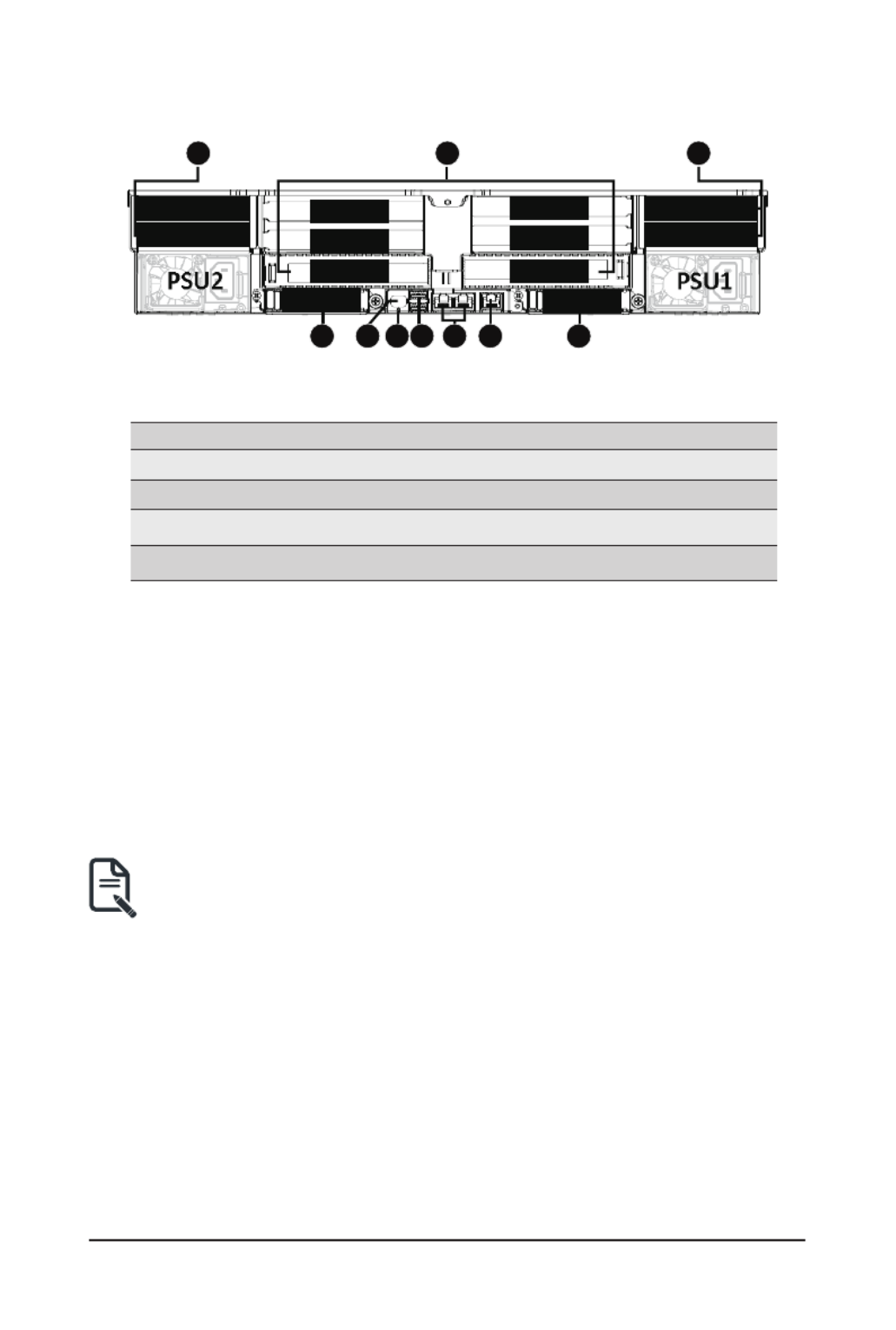
2-2 Rear View
321 4 5 6
78
6
8
SL 2OT
SL 10OT
SL 6OT
SL 3OT
SL 5OT
SL 9OT
SL 8OT
SL 12OT SL 11OT
SL 7OT
SL 4OT
SL 1OT
No. No.Description Description
1. 5.Mini DP Port Server Management LAN Port
2. 6.ID LED OCP 3.0 Slot (Option/SFF)
3. 7.USB 3.2 Gen1 Port x 2 PCIe Slot
4. 8.1GbE LAN Port x 2 2.5” Hard Drive Bay
• Refer to section for a detailed description of the function of 2-5 Rear System LAN LEDs
the LEDs.
- 23 -
System Appearance
(Note) If your server features RoT function, please see the following section for detail LED behavior.
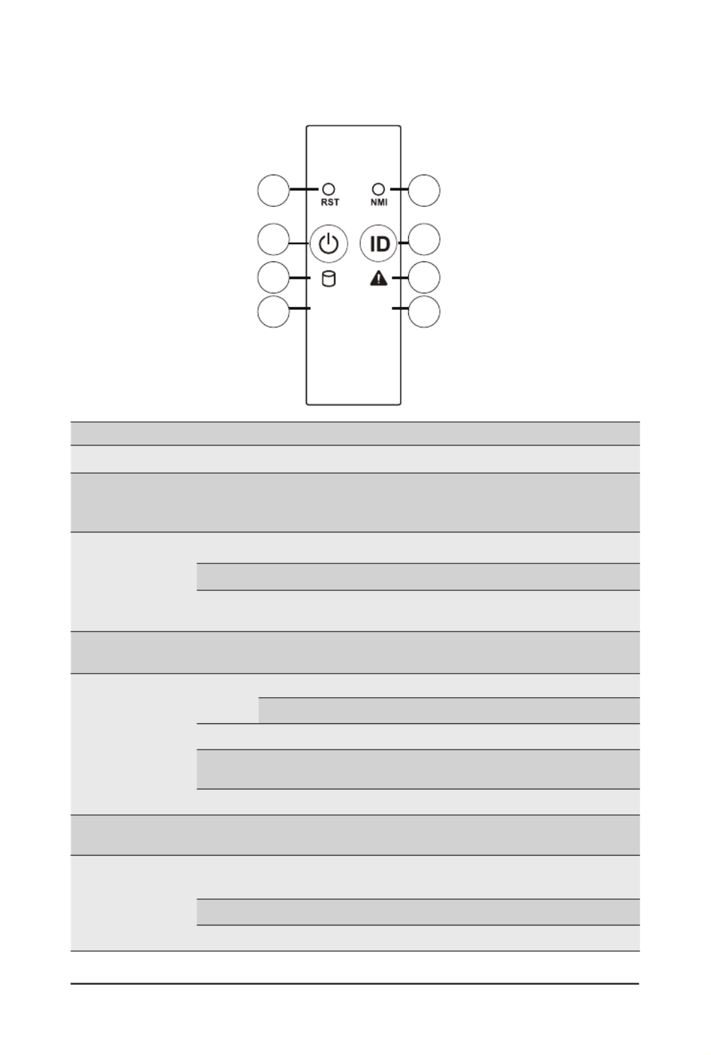
2-3 Front Panel LEDs and Buttons
L1 L2
1
3
5
7
2
4
6
8
No. Name Color Status Description
1. Reset Button -- Press this button to reset the system.--
2. NMI button -- --
Press this button for the server to generate a NMI to the
processor. If multiple-bit ECC errors occur, the server will
effectively be halted.
3. Power button
with LED
Green On Indicates the system is powered on.
Green Blink System is in ACPI S1 state (sleep mode).
N/A Off - System is not powered on or in ACPI S5 state (power off)
- System is in ACPI S4 state (hibernate mode)
4. ID Button with
LED
(Note)
This LED represents the RoT function LED behavior.
Please see the following section for detail LED behavior.
5. HDD Status
LED
(Note)
Green On Indicates locating the HDD.
Blink Indicates accessing the HDD.
Amber On Indicates HDD error.
Green/
Amber Blink Indicates HDD rebuilding.
N/A Off Indicates no HDD access or no HDD error.
6. System
Status LED
This LED represents the RoT function LED behavior.
Please see the following section for detail LED behavior.
7/8. LAN1/2 Active/
Link LED
Green On Indicates a link between the system and the network or no
access.
Green Blink Indicates data trasmission or receiving is occuring.
N/A Off Indicates no data transmission or receiving is occuring.
- 24 -
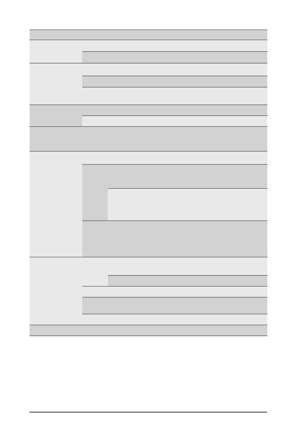
System Appearance
No. Name Color Status Description
1. ID Button with
LED
(Note)
Blue On Indicates the system identication is active.
N/A Off Indicates the system identication is disabled.
2. Power button
with LED
Green On Indicates the system is powered on.
Green Blink System is in ACPI S1 state (sleep mode).
N/A Off - System is not powered on or in ACPI S5 state (power off)
- System is in ACPI S4 state (hibernate mode)
3. ID Button
with LED
Blue On Indicates the system identication is active.
N/A Off Indicates the system identication is disabled.
4. NMI button -- --
Press this button for the server to generate a NMI to the
processor. If multiple-bit ECC errors occur, the server will
effectively be halted.
5. System Status
LED
(Note)
Green On Indicates system is operating normally.
Amber
On
Indicates a critical condition, may include:
- System fan failure
- System temperature
Blink
Indicates non-critical condition, may include:
- Redundant power module failure
- Temperature and voltage issue
- Chassis intrusion
N/A Off
Indicates system is not ready, may include:
- POST error
- NMI error
- Processor or terminator is missing
6. HDD Status
LED
Green On Indicates locating the HDD.
Blink Indicates accessing the HDD.
Amber On Indicates HDD error.
Green/
Amber Blink Indicates HDD rebuilding.
N/A Off Indicates no HDD access or no HDD error.
7. Reset Button -- Press this button to reset the system.--

- 26 -
System Appearance
NOTE!
1. EC FW is broken or not exited result in Microchip CEC1702 cannot load EC FW for authentication.
2 (1) Authentication fail include below scenarios
Conguration table is missing or modied
Public key is missing or modied
Protected area or signature is modied
Flash empty
3. if active ash is still authentication failed after recovery sequence, Microchip CEC1702 stop the process
and showing LED behavior.
4. If backup flash authentication is failed cause by configuration table, public key or protected area is
broken. Microchip CEC1702 stop the process and showing LED behavior.
5. Front panel LED is controlled by BMC or Microchip CEC1702. Once Microchip CEC1702 is working(Aut
or recovery), the front panel LED is controlled by Microchip CEC1702 and vice versa.
Active Flash Authentication (AUTH) Fail
BMC : AUTH Fail
(Note2) Blinks Blue
1 time per second
Blinks Green
1 time per second
BIOS : AUTH fail
(Note2) Blinks Blue
1 time per second
Blinks Amber
1 time per second
BMC : AUTH fail after doing recovery
(Note3)
Blinks Blue
2 times per second
[ON OFF OFF]
Blinks Green
2 times per second
[ON OFF OFF]
BIOS : AUTH fail after doing recovery
(Note3)
Blinks Blue
2 times per second
[ON OFF OFF]
Blinks Amber
2 times per second
[ON OFF OFF]
Backup Flash Authentication Fail
(Note4)
BMC : AUTH fail
Blinks Blue
2 times per second
[ON OFF ON OFF]
Blinks Green
2 times per second
[ON OFF ON OFF]
BIOS : AUTH fail
Blinks Blue
2 times per second
[ON OFF ON OFF]
Blinks Amber
2 times per second
[ON OFF ON OFF]
- 28 -
System Appearance
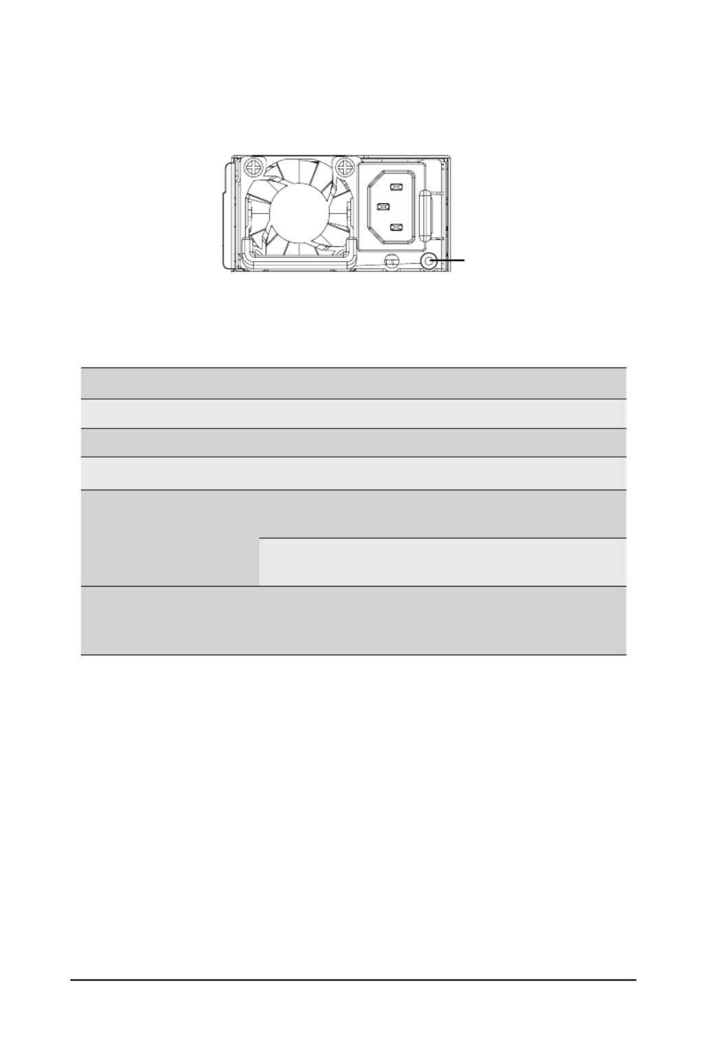
2-6 Power Supply Unit LED
PSU LED
State Description
OFF No AC power to all power supplies
1Hz Green Blinking AC present / only standby on / Cold redundant mode
2Hz Green Blinking Power supply rmware updateing mode
Amber
AC cord unplugged or AC power lost; with a second
power supply in parallel still with AC input power
Power supply critical event causing shut down:
failure, OCP, OVP, fan failure and UVP
0.5Hz Amber Blinking
Power supply warning events where the
power supply continues to operate:
high temp, high power, high current and slow fan
System Appearance
- 29 -
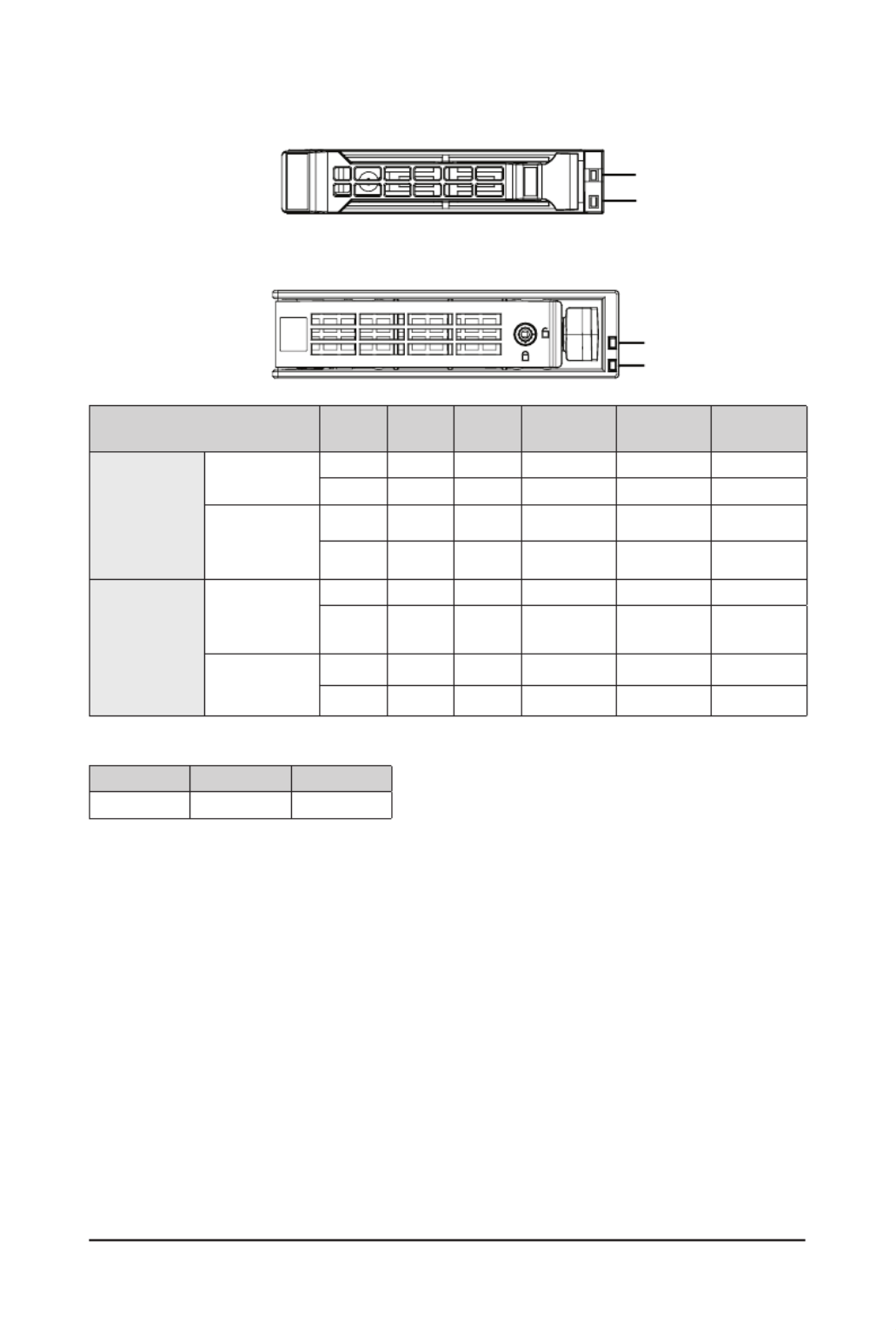
2-7 Hard Disk Drive LEDs
2.5” HD
D
LED #1
LED #2
LED #1
LED #2
3.5” HDD
RAID SKU LED #1 Locate HDD
Fault Rebuilding HDD Access HDD Present
(No Access)
No RAID
conguration
(via HBA)
Disk LED (LED
on Back Panel)
Green ON(*1) OFF OFFBLINK (*2)
Amber OFF OFF OFF OFF
Removed HDD
Slot (LED on
Back Panel)
Green ON(*1) OFF -- --
Amber OFF OFF -- --
RAID
conguration
(via HW RAID
Card or SW
RAID Card)
Disk LED
Green ON OFF OFFBLINK (*2)
Amber OFF ON (Low Speed:
2 Hz) OFF OFF
Removed
HDD Slot
Green ON(*1) OFF (*3) -- --
Amber OFF ON (*3) -- --
NOTE:
*1: Depends on HBA/Utility Spec.
*2: Blink cycle depends on HDD's activity signal.
*3: If HDD is pulled out during rebuilding, the disk status of this HDD is regarded as faulty.
LED #2 No HDDHDD Present
Green ON OFF

- 30 -
System Hardware Installation
Pre-installation Instructions
Computer components and electronic circuit boards can be damaged by discharges of static
electricity. Working on computers that are still connected to a power supply can be extremely
dangerous. Follow the simple guidelines below to avoid damage to your computer or injury to
yourself.
• Always disconnect the computer from the power outlet whenever you are working inside the
computer case.
• If possible, wear a grounded wrist strap when you are working inside the computer case.
Alternatively, discharge any static electricity by touching the bare metal system of the computer
case, or the bare metal body of any other grounded appliance.
• Hold electronic circuit boards by the edges only. Do not touch the components on the board
unless it is necessary to do so. Do not ex or stress the circuit board.
• Leave all components inside the static-proof packaging until you are ready to use the component
for the installation.
Chapter 3 System Hardware Installation

System Hardware Installation
- 31 -
3-1 Removing and Installing the Chassis Cover
Before you remove or install the system cover
• Make sure the system is not turned on or connected to AC power.
Follow these instructions to remove the chassis cover:
1. Remove the screw securing the chassis cover.
2. Unlock the plastic handle and pull the grip handle to open the panel cover.
3. Slide the cover cover to the rear of the system and then remove the cover in the direction indicated
by the arrow.
4. To reinstall the chassis cover follow steps 1-4 in reverse order.
4
23
1

- 32 -
System Hardware Installation
3-2 Removing and Installing the Hard Disk Drive
Read the following guidelines before you begin to install the hard disk drive:
• Take note of the HDD tray orientation before sliding it out.
• The tray will not t back into the bay if it is inserted incorrectly.
• Make sure that the hard disk drive is connected to the connector on the backplane.
Follow these instructions to install a 3.5" hard disk drive:
1. Press the release button.
2. Extend the locking lever.
3. Pull the locking lever in the direction indicated to remove the 3.5" HDD tray.
4. Pull the sides of the HDD tray in the direction indicated.
5. Slide the hard disk drive into the HDD tray.
6. Push the sides of the HDD tray back in the direction indicated to secure the hard disk drive in place.
7. Reinsert the HDD tray into the slot and close the locking lever.
2
1
3
4
5

- 33 -
System Hardware Installation
Follow these instructions to install a 2.5" hard disk drive into 3.5" HDD Tray:
1. Press the release button.
2. Extend the locking lever.
3. Pull the locking lever in the direction indicated to remove the HDD tray.
4. Align the hard disk drive with the positioning screw on the HDD tray.
5. Secure the hard disk drive with ve screws.
6. Reinsert the HDD tray into the slot and close the locking lever
2
1
3
4
5

- 34 -
System Hardware Installation
3-3 Removing and Installing the Fan Duct
Follow these instructions to remove the fan duct:
1. Lift up to remove the fan duct.
2. To reinstall the fan duct, align the fan duct with the guiding groove. Push down the fan duct until it is
rmly seated on the system.

System Hardware Installation
- 35 -
3-4 Removing and Installing the Heat Sink
Read the following guidelines before you begin to install the heat sink:
• Always turn off the computer and unplug the power cord from the power outlet before installing
the heat sink to prevent hardware damage.
• Unplug all cables from the power outlets.
• Disconnect all telecommunication cables from their ports.
• Place the system unit on a at and stable surface.
• Open the system according to the instructions.
WARNING!
Failure to turn off the server before you start installing components may cause serious damage. Do
not attempt the procedures described in the following sections unless you are a qualied service
technician.
Follow these instructions to install the heat sink:
1. Loosen the screws securing the heat sink in place in reverse order (6
g5g4g3g2g1).
2. Lift and remove the heat sink from the system.
3. To install the heat sink, reverse steps 1-2 while ensuring that you tighten the captive screws in
sequential order (1
g2g3g4g5g6) as seen in the image below.
2
1
3
3
3
3
3
1
1
1
1
1
2
2
2
2
2
4
4
4
4
4
5
5
5
5
5
6
6
6
6
6

- 36 -
System Hardware Installation
3-5 Removing and Installing the CPU
Read the following guidelines before you begin to install the CPU:
• Make sure that the motherboard supports the CPU.
• Always turn off the computer and unplug the power cord from the power outlet before installing
the CPU to prevent hardware damage.
• Unplug all cables from the power outlets.
• Disconnect all telecommunication cables from their ports.
• Place the system unit on a at and stable surface.
• Open the system according to the instructions.
WARNING!
Failure to properly turn off the server before you start installing components may cause serious
damage. Do not attempt the procedures described in the following sections unless you are a
qualied service technician.
Follow these instructions to install the CPU:
1. Loosen the three captive screws securing the CPU cover.
2. Flip open the CPU cover.
3. Remove the CPU carrier from the CPU frame using the handle on the CPU carrier.
4. Using the handle on the CPU carrier insert the new CPU carrier with CPU installed into the CPU
frame.
NOTE: Ensure the CPU is installed in the CPU carrier in the correct orientation, with the triangle
on the CPU aligned to the top left corner of the CPU carrier.
5. Flip the CPU frame with CPU installed into place in the CPU socket.
6. Flip the CPU cover into place over the CPU socket.
7. Tighten the CPU cover screw to secure the CPU cover in place.
8. Repeat steps 1-7 for the second CPU.
9. To remove the CPUs, follow steps 1-7 in reverse order.
1
Ext pernal ca
2
3

System Hardware Installation
- 37 -
• Lock the CPU by using a Torx T20 screwdriver to tighten screw.
• When installing the heatsink to CPU, use a Torx T20 screwdriver to tighten 6 captive nuts in
sequence as 1-6.
• The screw tightening torque: 13.5 ± 0.5 kgf-cm.
• To ensure the system operates properly, make sure the heatsink is seated on the processor
rmly.
CPU
4
5
6
7
8
3
3
3
3
3
1
1
1
1
1
2
2
2
2
2
4
4
4
4
4
5
5
5
5
5
6
6
6
6
6

- 38 -
System Hardware Installation
3-6 Removing and Installing Memory
3-6-1 Twelves Channel Memory Conguration
This motherboard provides 24 DDR5 memory sockets and supports Eight Channel Technology. After the
memory is installed, the BIOS will automatically detect the specications and capacity of the memory.
CPU1CPU0
DIMM_P0_F0
DIMM_P0_E0
DIMM_P0_B0
DIMM_P0_C0
DIMM_P0_D0
DIMM_P0_A0
DIMM_P0_G0
DIMM_P0_H0
DIMM_P0_K0
DIMM_P0_J0
DIMM_P0_I0
DIMM_P0_L0
DIMM_P1_R0
DIMM_P1_Q0
DIMM_P1_N0
DIMM_P1_O0
DIMM_P1_P0
DIMM_P1_M0
DIMM_P1_S0
DIMM_P1_T0
DIMM_P1_W0
DIMM_P1_V0
DIMM_P1_U0
DIMM_P1_X0
Read the following guidelines before you begin to install the memory:
• Make sure that the motherboard supports the memory. It is recommended that memory of the
same capacity, brand, speed, and chips be used.
• Always turn off the computer and unplug the power cord from the power outlet before installing
the memory to prevent hardware damage.
• Memory modules have a foolproof design. A memory module can be installed in only one
direction. If you are unable to insert the memory, switch the direction.

- 40 -
System Hardware Installation
3-6-4 Memory Population Table
EPYC Memory Speed based on DIMM Population (One DIMM per Channel)
DIMM
Type
DIMM Population Max EPYC 9004
DDR5 Frequency (MT/s)
DIMM 0
RDIMM 1R (1 Rank) 4800
2R (2 Ranks) 4800
3DS RDIMM
2S2R (4 Ranks) 4800
2S4R (8 Ranks) 4800
2S8Rx4 (16 ranks) 4800
EPYC Memory Speed based on DIMM Population (Two DIMM per Channel)
14-layer 93mil high-Dk PCB stackup
DIMM
Type
DIMM Population Max EPYC 9004
DDR5 Frequency (MT/s)
DIMM 0 DIMM 1
RDIMM
-- 1R 4800
1R 1R 4000
-- 2R 4400
1R 2R 3600
2R 2R 3600
3DS
-- 2S2R (4 Ranks) 4400
-- 2S4R (8 Ranks) 4400
-- 2S8R (16 Ranks) 4400
2S2R (4 Ranks) 2S2R (4 Ranks) 3600
2S4R (8 Ranks) 2S4R (8 Ranks) 3600
2S8Rx4 (16
Ranks) 2S8Rx4 (16 Ranks) 3600

- 41 -
System Hardware Installation
14-layer 74mil high-Dk PCB stackup/16-layer 93mil high-Dk PCB stackup
DIMM
Type
DIMM Population Max EPYC 9004
DDR5 Frequency (MT/s)
DIMM 0 DIMM 1
RDIMM
-- 1R 4800
1R 1R 4400
-- 2R 4800
1R 2R 4000
2R 2R 4000
3DS
-- 2S2R (4 Ranks) 4800
-- 2S4R (8 Ranks) 4800
-- 2S8R (16 Ranks) 4800
2S2R (4 Ranks) 2S2R (4 Ranks) 4000
2S4R (8 Ranks) 2S4R (8 Ranks) 4000
2S8Rx4 (16
Ranks) 2S8Rx4 (16 Ranks) 4000
Note:
• When only one DIMM is used, it must be populated in memory slot DIMM1.

System Hardware Installation
- 42 -
3-7 Removing and Installing the PCIe Card
• Voltages can be present within the server whenever an AC power source is connected. This
voltage is present even when the main power switch is in the off position. Ensure that the system
is powered off and all power sources have been disconnected from the server prior to installing a
PCIe card.
• Failure to observe these warnings could result in personal injury or damage to equipment.
• The PCIe riser assembly does not include a riser card or any cabling as standard. To install a
PCIe card, a riser card must be installed.
Follow these instructions to install a PCIe card:
1. Loosen the two thumbnail screws securing the riser bracket inside the system.
2. Lift up the riser bracket out of system.
3. Remove the screw securing the slot cover from riser bracket.
4. Orient the PCIe card with the riser guide slot and push in the direction of the arrow until the PCIe
card sits in the PCIe card connector.
NOTE: Some riser brackets allow for single or multiple PCIe cards.
Repeat steps 3-4 as necessary.
5. Secure the PCIe card with the screw.
6. Repeat steps 1-2 to install the PCIe card into the system.
1
2
2
1
4
3
5
6
4
3
6
5

- 43 -
System Hardware Installation
2
2
1
1
3
2
4
5
3
2
4
5

- 44 -
System Hardware Installation
3-8 Installing the Mezzanine Card
3-8-1 Installing the OCP 3.0 Mezzanine Card
Use of the following type of OCP 3.0 NIC is recommended:
• OCP 3.0 SFF with pull tab
• OCP 3.0 SFF with ejector latch
Follow these instructions to install an OCP 3.0 Mezzanine card:
1. Remove the two screws securing the OCP 3.0 card slot cover.
2. Remove the slot cover from the system.
3. Insert the OCP 3.0 card into the card slot ensuring that the card is rmly connected to the connector
on the motherboard.
4. Tighten the thumbnail screw to secure the OCP 3.0 card in place.
5. Reverse steps 3-4 to replace the OCP 3.0 card.
1
2
1
4
3

System Hardware Installation
- 45 -
3-9 Installing the M.2 Device and Heat Sink
CAUTION
The position of the stand-off screw will depend on the size of the M.2 device. The stand-off screw
is pre-installed for 22110 cards as standard. Refer to the size of the M.2 device and change the
position of the stand-off screw accordingly.
Follow these instructions to install the M.2 device:
1. Insert the M.2 SSD module into the slot.
2. Secure it with the screw, tightening as necessary to fasten the M.2 SSD module in place.
2
1
3-9-1 M.2 device with Heatsink
WARNING:
Please ensure a heatsink is attached to any M.2 device installed into the system. Installing an M.2
device without any heatsink may result in the system overheating or system performance being
throttled.
• Please Go to for specic M.2 Slot location.
• To install/remove the M.2 module and Heatsink use a No. 1 Phillips-head screwdriver with a screw
torque of 1.5 ± 0.2 kgf*cm
Follow these instructions to install the M.2 device and heat sink:
1. Insert the M.2 device into the M.2 connector.
2. Press down on the M.2 device.
3. Install the thermal pad of the M.2 device to the M.2 device.
4. Press down on the thermal pad.
5. Secure the M.2 device and its thermal pad to the motherboard with a single screw.
6. Reverse steps 1-2 to remove the M.2 device.
24
1
35

- 46 -
System Hardware Installation
3-10 Replacing the Fan Assembly
Follow these instructions to replace a fan assembly:
1. Flip the latches on the top of the fan outwards.
2. Using the latches, lift up the fan assembly from the chassis.
3. Reverse the previous steps to install the replacement fan assembly.
1
2
• Voltages can be present within the server whenever an AC power source is connected. This
voltage is present even when the main power switch is in the off position. Ensure that the
system is powered-down and all power sources have been disconnected from the server prior to
replacing a system fan.
Failure to observe these warnings could result in personal injury or damage to equipment.

System Hardware Installation
- 47 -
3-11 Removing and Installing the Power Supply
Follow these instructions to replace the power supply:
1. Flip up and then grasp the power supply handle.
2. Press the retaining clip on the right side of the power supply unit in the direction indicated.
3. Pull out the power supply unit using the handle.
4. Insert the replacement power supply unit rmly into the chassis. Connect the AC power cord to the
replacement power supply.
5. Repeat steps 1-4 for replacement of the second power supply.
3
1
2
4
- 48 -
System Hardware Installation
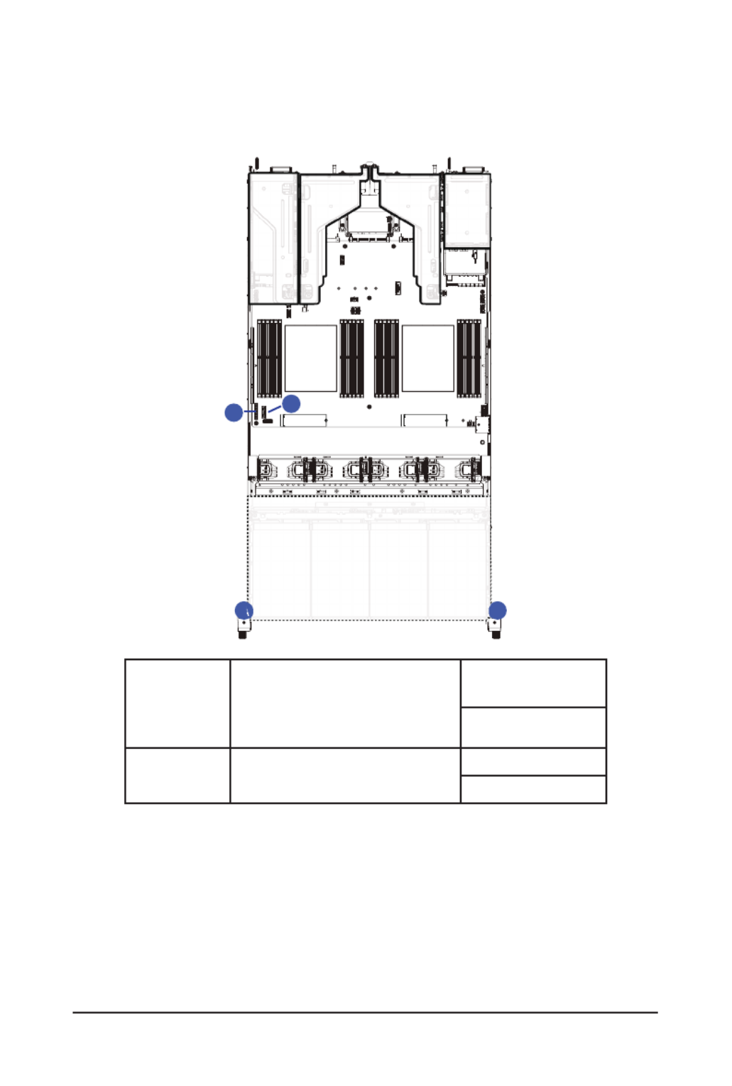
3-11-1 R283-Z90-AAD1
CPU1CPU0
A
A B
B
A Front Panel LEDs and Buttons Cable
Motherboard
: FP_1
Front IO Board: FP_1
Front IO Board: FP_1
B Front Panel USB 3 Ports Cable Motherboard
: FUSB_1
--
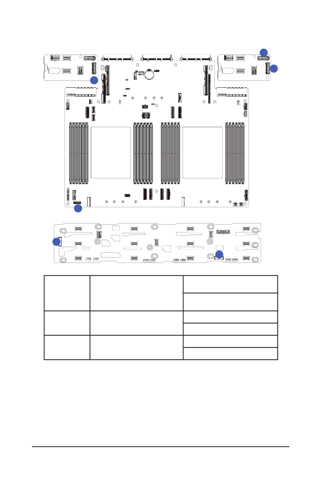
3-12 Cable Routing

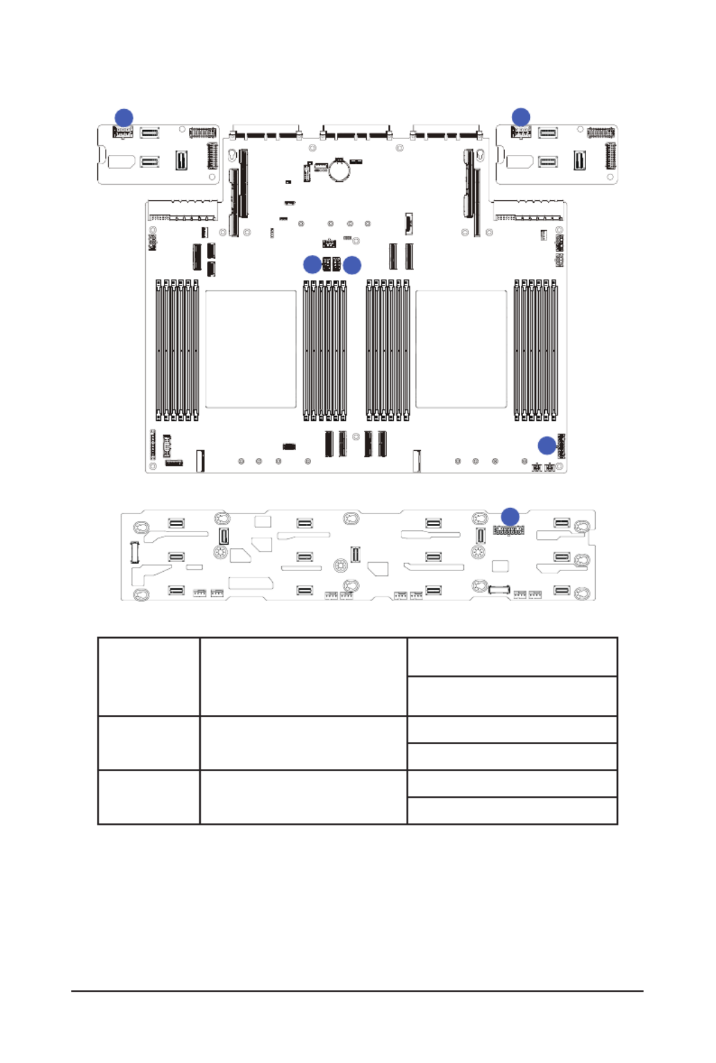
- 49 -
System Hardware Installation
CPU1CPU0
A
A
B
B
C
C
A HDD Backplane Board Signal Cable
Motherboard
: BP_1
F/ HDD Board: BP_1
B HDD Backplane Board Signal Cable
F/ HDD Board
: BP_SERIES
R/ HDD Board
: BP_1
C HDD Backplane Board Signal Cable R/ HDD Board
: BP_SERIES
R/ HDD Board
: BP_1
System Hardware Installation
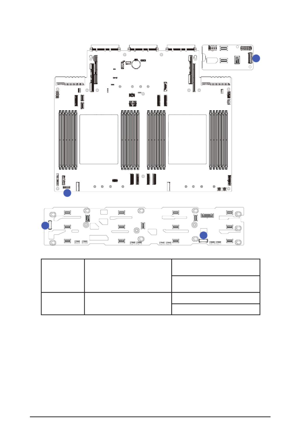
- 50 -
CPU1CPU0
A
B
B
C
C
A
A HDD Backplane Board Power Cable
Motherboard
: BP_ATX1
F/ HDD Board: ATX1
B HDD Backplane Board Power Cable Motherboard
: BP_ATX2
R/ HDD Board: BP_2X3
C HDD Backplane Board Power Cable Motherboard
: BP_ATX4
R/ HDD Board: BP_2X3

- 51 -
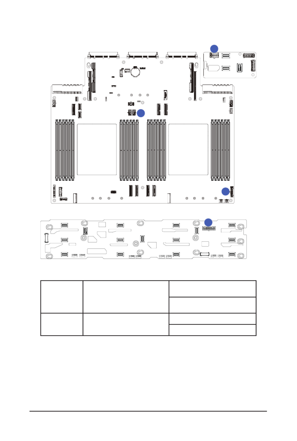
System Hardware Installation
CPU1CPU0
A
A
A
B
B
C C
C
A SATA Cable
Motherboard
: P0_MCIO_0
F/ HDD Board:
SL_SAS0
SL_SAS1
B SATA Cable Motherboard
: P0_MCIO_1
F/ HDD: SL_SAS2
C SATA Cable
Motherboard
: P0_MCIO_
R/ HDD Board:
SL_SAS0
SL_SAS0

- 52 -
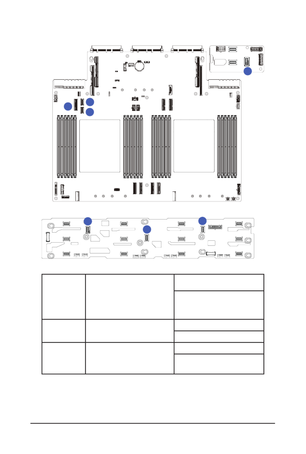
System Hardware Installation
CPU1CPU0
A
A
A
A
B
B
B
C
A
D
D
D
C
C
B
B
ANVMe 0-3
Cable
Motherboard
: OCP1
CNVMe 8-9
Cable
Motherboard
:
P1_MCIO_0
F/ HDD Board:
Top to bottom/Right to Left:
U.2 0
U.2 1
U.2 2
U.2 3
F/ HDD Board:
U.2 8
U.2 9
BNVMe 4-7
Cable
Riser Card CRS101Q
D
NVMe 10-
11
Cable
Motherboard
:
P1_MCIO_1
F/ HDD Board:
Top to bottom/Right to Left:
U.2 4
U.2 5
U.2 6
U.2 7
F/ HDD Board:
U.2 10
U.2 11

- 53 -
System Hardware Installation
CPU1CPU0
A
B
A
B
A XGMI CPU1 Cable
Motherboard
: MCIO_G1_0
Motherboard
: MCIO_G0_1
B XGMI CPU0 Cable Motherboard
: MCIO_G1_1
Motherboard
: MCIO_G0_0
- 55 -
System Hardware Installation
CPU1CPU0
A
A
B
B
C
C
A HDD Backplane Board Signal Cable
Motherboard
: BP_1
F/ HDD Board: BP_1
B HDD Backplane Board Signal Cable F/ HDD Board
: BP_SERIES
R/ HDD Board
: BP_1
C HDD Backplane Board Signal Cable R/ HDD Board
: BP_SERIES
R/ HDD Board
: BP_1

- 56 -
System Hardware Installation
CPU1CPU0
A
B
B
C
C
A
A HDD Backplane Board Power Cable
Motherboard
: BP_ATX1
F/ HDD Board: ATX1
B HDD Backplane Board Power Cable Motherboard
: BP_ATX2
R/ HDD Board: BP_2X3
C HDD Backplane Board Power Cable
Motherboard
: BP_ATX4
R/ HDD Board: BP_2X3

- 57 -
System Hardware Installation
CPU1CPU0
A
A
A
B
B
C C
C
A SATA Cable
Motherboard
: P0_MCIO_0
F/ HDD Board:
SL_SAS0
SL_SAS1
B SATA Cable Motherboard
: P0_MCIO_1
F/ HDD: SL_SAS2
C SATA Cable
Motherboard
: P0_MCIO_2
R/ HDD Board:
SL_SAS0
SL_SAS0

- 58 -
System Hardware Installation
CPU1CPU0
A
A
B
B
B
A
A NVMe 8-9 Cable
Motherboard
: P1_MCIO_0
F/ HDD Board:
U.2 8
U.2 9
B NVMe 10-11 Cable
Motherboard
: P1_MCIO_1
F/ HDD Board:
U.2 10
U.2 11

- 59 -
System Hardware Installation
CPU1CPU0
A
B
A
B
A XGMI CPU1 Cable
Motherboard
: MCIO_G1_0
Motherboard
: MCIO_G0_1
B XGMI CPU0 Cable Motherboard
: MCIO_G1_1
Motherboard
: PMCIO_G0_0

- 60 -
System Hardware Installation
3-12-2 R283-Z90-AAD3
CPU1CPU0
A
A B
B
A Front Panel LEDs and Buttons Cable
Motherboard
: FP_1
Front IO Board: FP_1
Front IO Board: FP_1
B Front Panel USB 3 Ports Cable
Motherboard
: FUSB_1
--
- 61 -
System Hardware Installation
CPU1CPU0
A
A
B
B
A HDD Backplane Board Signal Cable
Motherboard
: BP_1
F/ HDD Board: BP_1
B HDD Backplane Board Signal Cable F/ HDD Board
: BP_SERIES
R/ HDD Board
: BP_1
- 62 -
System Hardware Installation
CPU1CPU0
A
B
B
A
A HDD Backplane Board Power Cable
Motherboard
: BP_ATX1
F/ HDD Board: ATX1
B HDD Backplane Board Power Cable
Motherboard
: BP_ATX2
R/ HDD Board: BP_2X3
- 63 -
System Hardware Installation
CPU1CPU0
A
A
A
B
B
C
C
A SATA Cable
Motherboard
: P0_MCIO_0
F/ HDD Board:
SL_SAS0
SL_SAS1
B SATA Cable Motherboard
: P0_MCIO_1
F/ HDD: SL_SAS2
C SATA Cable
Motherboard
: P0_MCIO_2
R/ HDD Board:
SL_SAS0
- 64 -
System Hardware Installation
CPU1CPU0
A
ABB
A Riser Card Cable
Motherboard
: P1_MCIO_0
Motherboard Slot: SLOT1
B Riser Card Cable Motherboard
: P1_MCIO_1
CRS202N

- 68 -
Motherboard Components
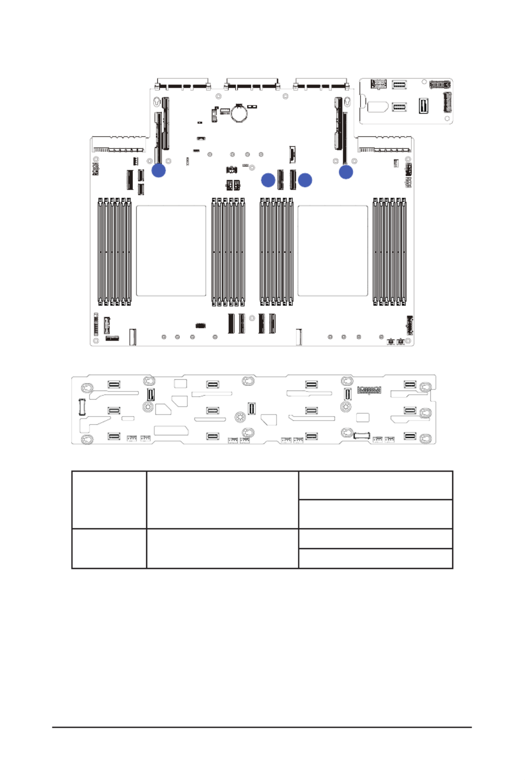
4-2 Jumper Settings
CPU1CPU0
BMC1
BMC2
BIOS1BIOS2
NCSI Swch
Onboa LANrd
SW.1
OFF
NCSI_SW
-
ON OFF Slot#2 OCP3.0
G-SC MB
ON ON Slot#1 OCP3.0
Clear CMOS
CLR_CMOS
EnableDe ultfa
123
J1 ON OFF
1HOST_SMBUS_SEL BIOS dened
2Reserved Reserved
3BIOS_PWD Normal [Default]Clear supervisor password
4BIOS_RCVR BIOS recovery mode Normal [Default]

Motherboard Components
- 69 -
4-3 G-SC Module
4-3-1 CDCR112
BMC1
BMC2
BIOS1BIOS2
1 2 3 4 5
Item Description
110/100/1000 Server Management LAN Port
2 1GbE LAN Port #2
3 1GbE LAN Port #1
4USB 3.2 Gen1 Port x 2
5 Mini DP Port
BIOS Setup
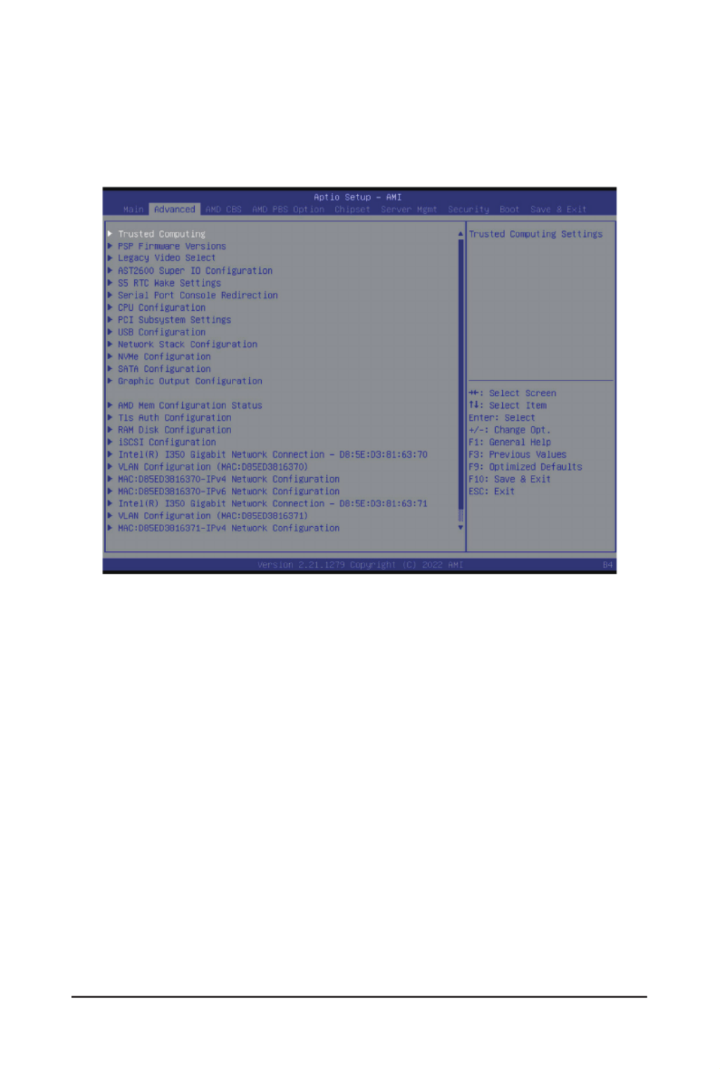
- 79 -
5-2 Advanced Menu
The Advanced Menu displays submenu options for conguring the function of various hardware components.
Select a submenu item, then press <Enter> to access the related submenu screen.
When Boot Mode Select is set to UEFI (Default)
Termékspecifikációk
| Márka: | Gigabyte |
| Kategória: | szerver |
| Modell: | R283-Z90 |
Szüksége van segítségre?
Ha segítségre van szüksége Gigabyte R283-Z90, tegyen fel kérdést alább, és más felhasználók válaszolnak Önnek
Útmutatók szerver Gigabyte

16 December 2024
11 Október 2024
6 Október 2024
29 Augusztus 2024
29 Augusztus 2024
29 Augusztus 2024
29 Augusztus 2024
29 Augusztus 2024
29 Augusztus 2024
29 Augusztus 2024
Útmutatók szerver
- szerver Sony
- szerver Fujitsu
- szerver Acer
- szerver StarTech.com
- szerver Lenovo
- szerver Toshiba
- szerver HP
- szerver Medion
- szerver Vimar
- szerver Technics
- szerver Rocstor
- szerver Digitus
- szerver TRENDnet
- szerver Dell
- szerver Tripp Lite
- szerver Conceptronic
- szerver Blackmagic Design
- szerver Hikvision
- szerver Netgear
- szerver Asus
- szerver ELAC
- szerver Synology
- szerver Supermicro
- szerver ZyXEL
- szerver Smart-AVI
- szerver Planet
- szerver Ernitec
- szerver Black Box
- szerver MSI
- szerver Cisco
- szerver ATen
- szerver APC
- szerver SEH
- szerver Western Digital
- szerver HGST
- szerver D-Link
- szerver Monacor
- szerver Moxa
- szerver Abus
- szerver Veritas
- szerver Atlona
- szerver Lindy
- szerver Areca
- szerver QNAP
- szerver NEC
- szerver Siig
- szerver Eaton
- szerver Gefen
- szerver Kathrein
- szerver IStarUSA
- szerver Lantronix
- szerver Provision-ISR
- szerver Axis
- szerver NETSCOUT
- szerver Sitecom
- szerver ACTi
- szerver Megasat
- szerver KanexPro
- szerver Kramer
- szerver Allnet
- szerver SilverStone
- szerver Maxdata
- szerver AVerMedia
- szerver Matrox
- szerver Flir
- szerver Buffalo
- szerver GeoVision
- szerver LevelOne
- szerver LaCie
- szerver Valcom
- szerver Asustor
- szerver Intel
- szerver Fantec
- szerver Freecom
- szerver Seagate
- szerver Iomega
- szerver Digi
- szerver Revox
- szerver Luxman
- szerver Ibm
- szerver Sonnet
- szerver TAIDEN
- szerver Advantech
- szerver Extron
- szerver Avocent
- szerver Intellinet
- szerver Teradek
- szerver Silex
- szerver Hanwha
- szerver In Win
- szerver Sun
- szerver MvixUSA
- szerver Dual Bay
- szerver Raidsonic
- szerver EMC
- szerver Infortrend
- szerver Opengear
- szerver G-Technology
- szerver EXSYS
- szerver Chenbro Micom
- szerver Middle Atlantic
- szerver Mr. Signal
- szerver Atlantis Land
- szerver C2G
- szerver Promise Technology
- szerver Mobotix
- szerver Origin Storage
Legújabb útmutatók szerver

9 Április 2025
3 Április 2025

2 Április 2025
29 Március 2025
29 Március 2025
29 Március 2025
24 Március 2025
24 Március 2025

15 Január 2025
15 Január 2025