Használati útmutató Gigabyte R282-NO0
Olvassa el alább 📖 a magyar nyelvű használati útmutatót Gigabyte R282-NO0 (137 oldal) a szerver kategóriában. Ezt az útmutatót 9 ember találta hasznosnak és 2 felhasználó értékelte átlagosan 4.5 csillagra
Oldal 1/137

Gigabyte Server Management Console
User's Guide
Rev. 1.0

Copyright
© 2023 Giga Computing Technology CO., LTD. All rights reserved.
The trademarks mentioned in this manual are legally registered to their respective owners.
Disclaimer
Information in this manual is protected by copyright laws and is the property of Giga Computing.
Changes to the specications and features in this manual may be made by Giga Computing
without prior notice. No part of this manual may be reproduced, copied, translated, transmitted, or
published in any form or by any means without Giga Computing's prior written permission.
Documentation Classications
In order to assist in the use of this product, Giga Computing provides the following types of
documentation:
User Manual: detailed information & steps about the installation, conguration and use of this
product (e.g. motherboard, server barebones), covering hardware and BIOS.
User Guide: detailed information about the installation & use of an add-on hardware or
software component (e.g. BMC rmware, rail-kit) compatible with this product.
Quick Installation Guide: a short guide with visual diagrams that you can reference easily for
installation purposes of this product (e.g. motherboard, server barebones).
Please see the support section of the online product page to check the current availability of these
documents.
For More Information
For related product specications, the latest rmware and software, and other information please visit our website at
http://www.gigabyte.com/Enterprise
For GIGABYTE distributors and resellers, additional sales & marketing materials are available from our reseller
portal: http://reseller.b2b.gigabyte.com
For further technical assistance, please contact your GIGABYTE representative or visit
https://esupport.gigabyte.com/ to create a new support ticket
For any general sales or marketing enquiries, you may also message GIGABYTE server directly by email:
server.grp@gigabyte.com

- 3 -
Table of Contents
Chapter 1 Getting Started 5 ...............................................................................................
1-1 Software Requirement 5 .....................................................................................
1-2 GigabyteManagementConsoleNetworkConguration .................................. 6
1-3 Log In Gigabyte Management Console 7 ............................................................
1-3-1 Required Browser Settings: 8 ......................................................................................
1-4 Quick Button and Logged-in User 9 ....................................................................
1-5 Help ................................................................................................................ 10
1-6 Menu Bar 10 ........................................................................................................
Chapter 2 Enter Gigabyte Management Console .........................................................11
2-1 Dashboard ...................................................................................................... 11
2-2 Sensor ............................................................................................................ 12
2-2-1 Sensor Detail 13 ..........................................................................................................
2-2-2 Sensor Events 14 ........................................................................................................
2-3 System Inventory 15 ...........................................................................................
2-3-1 CPU Inventory 15 ........................................................................................................
2-3-2 DIMM Inventory 17 ......................................................................................................
2-3-3 PCI Inventory 18 ..........................................................................................................
2-3-4 HDD Inventory 19 ........................................................................................................
2-3-5 NIC Inventory 20 ..........................................................................................................
2-4 FRU Information 21 .............................................................................................
2-5 Logs & Reports 23 ..............................................................................................
2-5-1 IPMI Event Log 23 .......................................................................................................
2-5-2 System Log 24 .............................................................................................................
2-5-3 Audit Log 25 ................................................................................................................
2-5-4 Video Log 26 ...............................................................................................................
2-6 Settings .......................................................................................................... 27
2-6-1 Captured BSOD 27 ......................................................................................................
2-6-2 Date & Time ............................................................................................................28
2-6-3 External User Services 29 ...........................................................................................
2-6-4 KVM Mouse Settings 39 ..............................................................................................
2-6-5 Log Settings 40 ............................................................................................................
2-6-6 Manage Licenses 43 ...................................................................................................
2-6-7 Media Redirection Settings 43 .....................................................................................
2-6-8 Network Settings 48 ....................................................................................................
2-6-9 PAM Order Settings 56 ................................................................................................
2-6-10 Platform Event Filter 57 ...............................................................................................
2-6-11 Services ..................................................................................................................65

- 4 -
2-6-12 SMTP Settings 69 ........................................................................................................
2-6-13 SSL Settings 72 ...........................................................................................................
2-6-14 System Firewall 77 ......................................................................................................
2-6-15 User Management 85 ..................................................................................................
2-6-16 Video Recording 89 .....................................................................................................
2-6-17 FanProle ..............................................................................................................97
2-6-18 Power Consumption 99 ...............................................................................................
2-6-19 IMPI Interfaces 100 .....................................................................................................
2-6-20 RAID Management 101 ...............................................................................................
2-7 Remote Control ............................................................................................ 112
2-8 Images Redirection ...................................................................................... 118
2-8-1 Remote Media ......................................................................................................119
2-9 Power Control 120 ..............................................................................................
2-10 Maintenance Group 121 ......................................................................................
2-10-1 BackupConguration ...........................................................................................122
2-10-2 Firmware Image Location 123 .....................................................................................
2-10-3 Firmware Information 124 ............................................................................................
2-10-4 Firmware Update 125 ..................................................................................................
2-10-5 PreserveConguration .........................................................................................130
2-10-6 RestoreConguration ...........................................................................................134
2-10-7 Restore Factory Defaults 135 ......................................................................................
2-10-8 System Administrator ............................................................................................136
2-10-9 Sign Out 137 ................................................................................................................

- 5 -
Getting Started
1-1 Software Requirement
• Client machine with 8GB RAM.
• If the client machine has 4GB RAM, there will be lag in video/keyboard/mouse
functionality.
Supported Browsers
• Chrome latest version.
• IE 11 and above.
• Firefox (with limited support).
It is advisable to use Chrome or IE for H5Viewer since Firefox has its own Note:
memory limitations.
Chapter 1 Getting Started

- 6 -
Getting Started
1-2 Gigabyte Management Console Network Conguration
Follow the instruction to enable the console redirection function.
1. You can gather the IP address on the POST screen.
2. Or, Go to BIOS setup menu.
3. Select .Server Management
4. Select . BMC network Conguration
5. DeneCongurationAddresssourcetoDynamicBmcDhcporStatic.
6. Save and Exit.
7. The BMC IP Address Station IP address will appear on the parameter.
8. SavethecongurationandexitBIOSsetupmenu.
Getting Started - 7 -
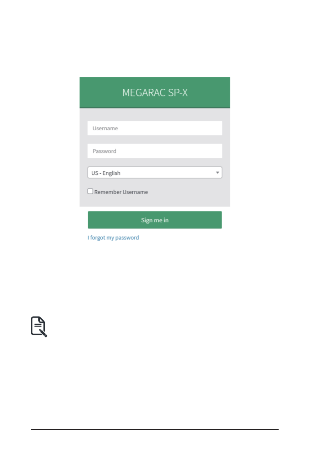
1-3 Log In Gigabyte Management Console
To access the Gigabyte Management Console, the MegaRAC utility will prompt you to enter the
User Name and Password.
Theeldsareexplainedasfollows:
For basic login to the MegaRAC UI, use the following login:
• Username: admin
• Password: Refer to unique MB serial number.
• US - English: Changes the interface language.
NOTE!
If your motherboard / server version is older than G9 (upgrade version), then use the
following login:
Username: admin
Password: password
This serial number can be found on the serial number sticker located on the motherboard of
every GIGABYTE server motherboard and system. The unique pre-programmed password will
be the last 11 characters of the serial number. For example, for the below serial number, the
password will be “JG4P6400027

- 8 -
Getting Started
GIGABYTEwillalsoafxnewstickersthatdisplaytheuniqueBMCpassword(examplebelow)to
both the product box (packaging) and to the CPU cover (for motherboards sold separately) or the
server chassis.
Please see the reference guide below / attached for where to find locations of this sticker
according to product / model type.
Products that have been implemented with this change will be indicated as version G9 on the
“Upgrade Version” sticker located on the motherboard / motherboard anti-static packaging /
server chassis / server packaging.
Remember Username: Check this option to remember your login credentials.
Sign me in: After entering the required credentials, click the to login to GUI.Sign me in
I forgot my password: If you forget your password, you can generate a new one using this link.
Enter the user name, click on link. This will send the newly generated Forgot Password
passwordtotheconguredEmail-IDfortheuser.
1-3-1 Required Browser Settings:
Allow le download from this site: For Internet Explorer, Choose Tools ->Internet Options
->Security Tab, based on device setup, select among Internet, Local intranet, trusted sites and
restricted sites. Click .... In the Security Settings - Zone dialog opened, under Custom level
settings, find Downloads option, Enable File download option. Click to the entire dialog OK
boxes.
ForallOtherBrowsers,acceptledownloadwhenprompted.
Enable javascript for this site: The icon indicates whether the javascript setting is enabled in
browser.
Enable cookies for this site: The icon indicates whether the cookies setting are enabled in
browser.
Cookies must be enabled in order to access the website.

Getting Started - 9 -
1-4 Quick Button and Logged-in User
The user information and quick buttons are located at the top right of the Web GUI. A screenshot
of the logged-in user information is shown below.
User Information
The logged-in user information shows the logged-in user, his/her privilege and the four quick
buttons allowing you to perform the following functions:
Logged-in user and its privilege level
Thisoptionshowsthelogged-inusernameandprivilege.Therearevekindsofprivileges.
User: Only valid commands are allowed.
Operator: All BMC commands are allowed except for the configuration commands that can
change the behavior of the out-of-hand interfaces.
Administrator: All BMC commands are allowed.
No Access: Login access denied.
OEM: All OEM commands are allowed.
Refresh: Click the icon to reload the current page.
Sync: Click the icon to synchronize with Latest Sensor and Event Log updates.
US - English: Click to select the language of the Web GUI.
Warning: Click to view the warning messages.
Notication:Clicktheicontoviewthenoticationmessages.
Getting Started - 10 -
1-5 Help
Help - The Help icon (?) is Located at the top right of the each page in Web GUI. Click this help
icontoviewmoredetailedelddescriptions.
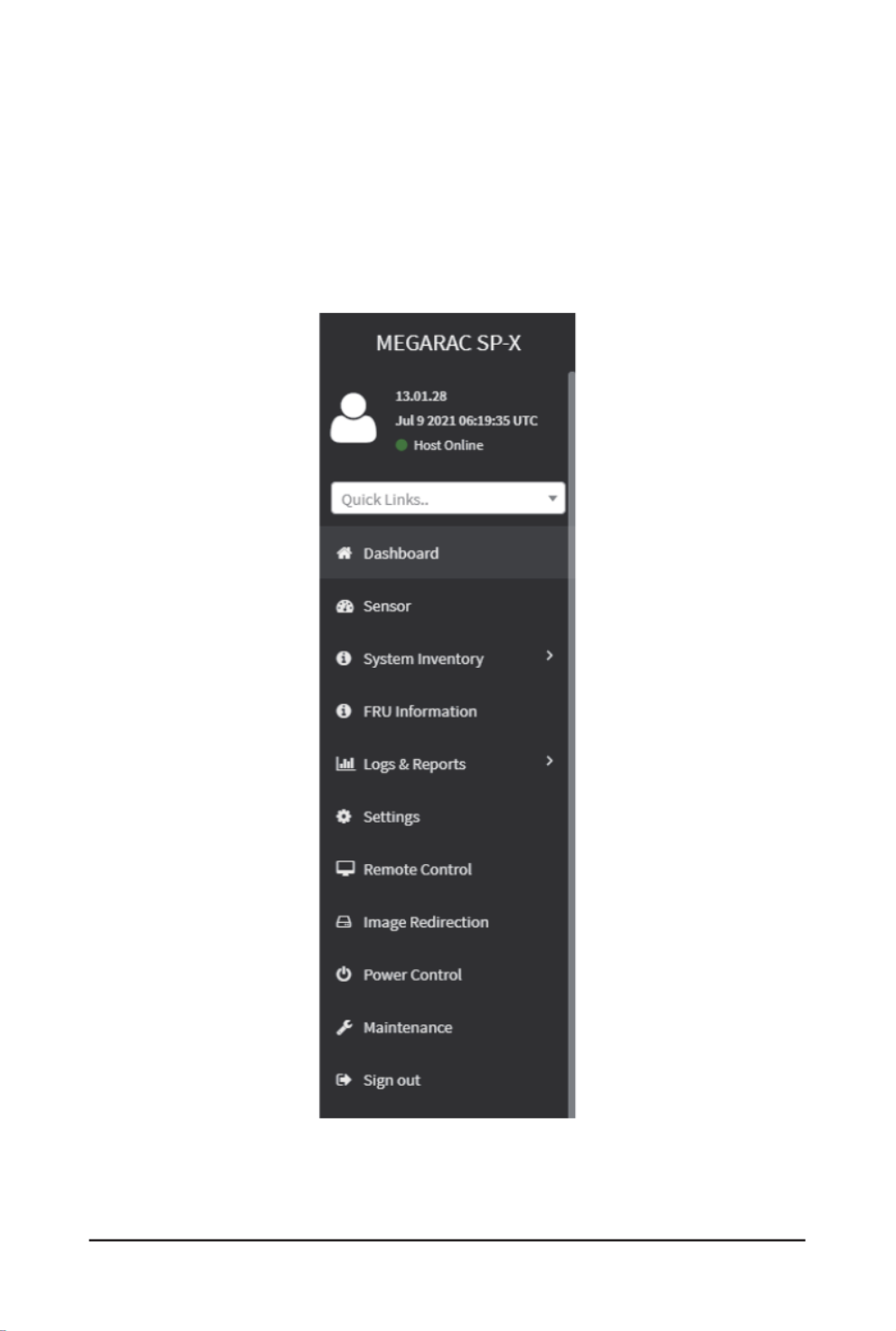
1-6 Menu Bar
The menu bar displays the following:
- 11 -
Gigabyte Server Management Console
Chapter 2 Enter Gigabyte Management Console
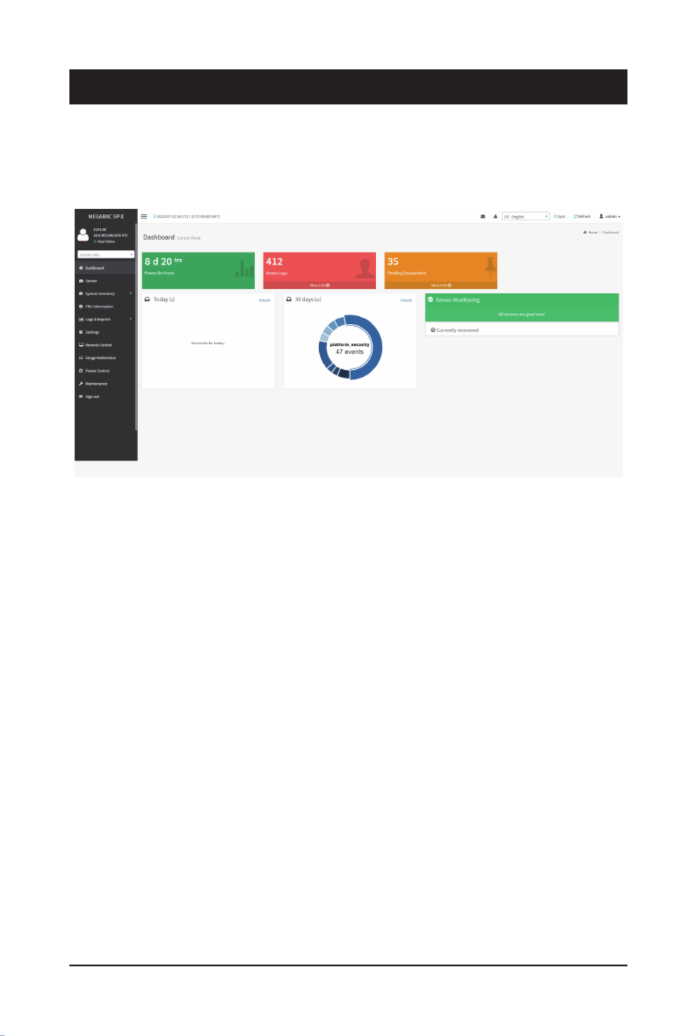
2-1 Dashboard
The Dashboard page gives the overall information about the status of a device.
To open the Dashboard page, click from the menu bar. It displays the following:Dashboard
Dashboard
A brief description of the Dashboard page is given below.
Power-On Hours
It indicates the power-on time.
Pending Deassertions
It lists the all pending events incurred by various sensors and occupied/available space in logs
can be viewed. To know about the pending events details, click the More info link. This navigates
to the Event Log page.
Access Logs
A graphical representation of all events incurred by various sensors and occupied/available space
in logs can be viewed, if you click on the More info link, you can view the Audit Log page.
Today & 30 Days (Event Logs)
This page displays the list of event logs occurred by the different sensors on this device. Click
Details link on Today and 30 days to view the event logs for Today and 30 days respectively.
Sensor Monitoring
It lists all the critical sensors on the device. If you click on any list sensor, you can view the
Sensor detail page with the Sensor information and Sensor Events details.

Gigabyte Server Management Console
- 12 -
2-2 Sensor
The Sensor Readings page displays all the sensor related information.
To open the Sensor Readings page, click Sensor from the menu. Click on any sensor to show
more information about that particular sensor, including thresholds and a graphical representation
of all associated events.
A sample screenshot of Sensor Readings page is shown below.
The Sensor Readings page contains the following information:
In this Sensor Reading page, Live readings for all the available sensors with details like Sensor
Name, Status, Current Reading and Behavior will be appeared, else you can choose the sensor
type that you want to display from the list. Some examples for sensors are Temperature Sensors,
Fan Sensors, Watchdog Sensors and Voltage Sensors etc.
Note: Four DIMM Temp sensors are deployed for monitoring the DIMM temperature on the
system. Users must take notice that the live reading of each DIMM Temp sensor indicates the
temperatureofaDIMMgroup,notthetemperatureofaspecicDIMM.
: Four DIMM Temp sensors are deployed for monitoring the DIMM temperature on Note
the system. Users must take notice that the live reading of each DIMM Temp sensor
indicatesthetemperatureofaDIMMgroup,notthetemperatureofaspecicDIMM.

- 13 -
Gigabyte Server Management Console
2-2-1 Sensor Detail
Select a particular sensor from the Critical Sensor or Normal Sensor lists. The Sensor Information
as Live Widget and Thresholds for the selected sensor will be displayed as shown below.
: For Illustrative Purpose, a sample screenshot of Sensor detail page with Change Note
Thresholds option is shown and explained below.
: Widgets are little gadgets, which provide real time information about a particular Note
sensor.Usercantrackasensor'sbehavioroveraspecicamountoftimeatspecic
intervals. The result will be displayed as a line graph in the widget. The session will not
expire, until the widgets gets a live data of the last widget that is kept opened.
For the selected sensor, this widget gives a dynamic representation of the readings for
the sensor.
There are six types of thresholds:
• Lower Non-Recoverable (LNR)
• Lower Critical (LC)
• Lower Non-Critical (LNC)
• Upper Non-Recoverable (UNR)
• Upper Critical (UC)
• Upper Non-Critical (UNC)
The threshold states could be Lower Non-critical - going low, Lower Non-critical - going high,
Lower Critical - going low, Lower Critical - going high, Lower Non-recoverable - going low, Lower
Non-recoverable - going high, Upper Non-critical - going low, Upper Non-critical - going high,
Upper Critical - going low, Upper Critical - going high, Upper Non-recoverable - going low, Upper
Non-recoverable - going high.
A graphical view of these events (Number of Entries vs. Thresholds) can be viewed as shown in
the Sensor Readings page screenshot.

Gigabyte Server Management Console
- 14 -
2-2-2 Sensor Events
The Sensor Events page displays information about events that have triggered the system’s
sensor. A sample screenshot of Sensor Events page is shown below.

- 15 -
Gigabyte Server Management Console
2-3 System Inventory
The System Inventory page displays the following information:
• CPU Inventory
• DIMM Inventory
• PCI Inventory
• HDD Inventory
• NIC Inventory
A screenshot displaying the menu items under System Inventory is shown below.
A detailed description of System Inventory is given below.
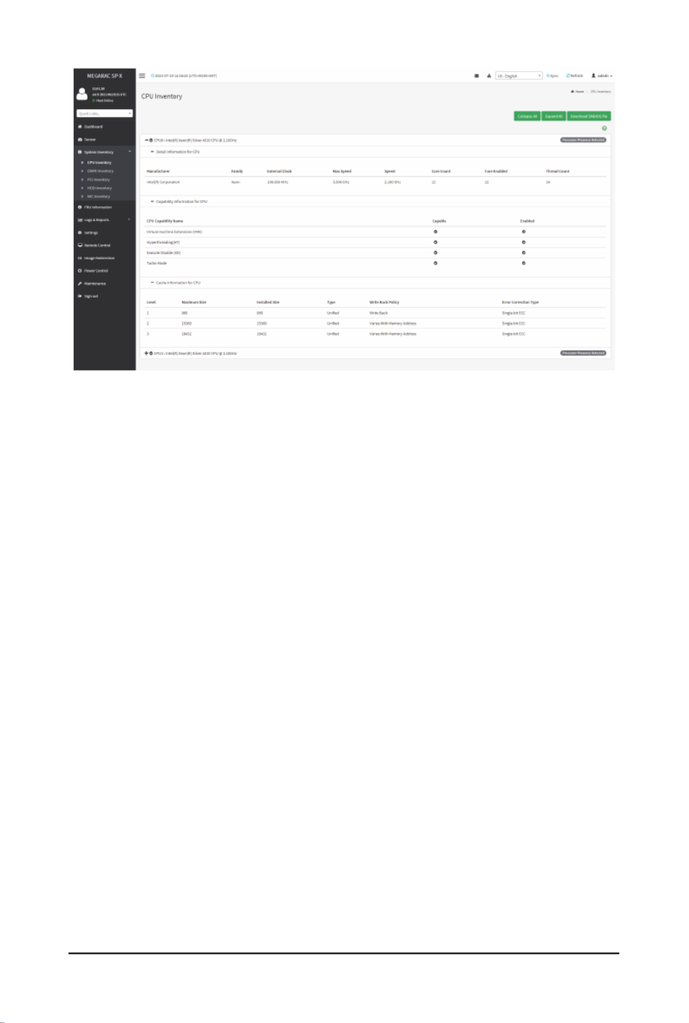
2-3-1 CPU Inventory
This page displays all detected CPUs on this device. Select one CPU to see the details of that
entry or click on to view all entries in details. Click DownloadExpand All SMBIOS file to
downloadtheSMBIOSle.
Gigabyte Server Management Console
- 16 -

- 17 -
Gigabyte Server Management Console
2-3-2 DIMM Inventory
This page displays all detected DIMMs on this device. It allows you to see memory attributes,
individual memory details or all entries in detail by clicking on . Click Expand All Download
SMBIOS letodownloadtheSMBIOSle.
Gigabyte Server Management Console
- 18 -
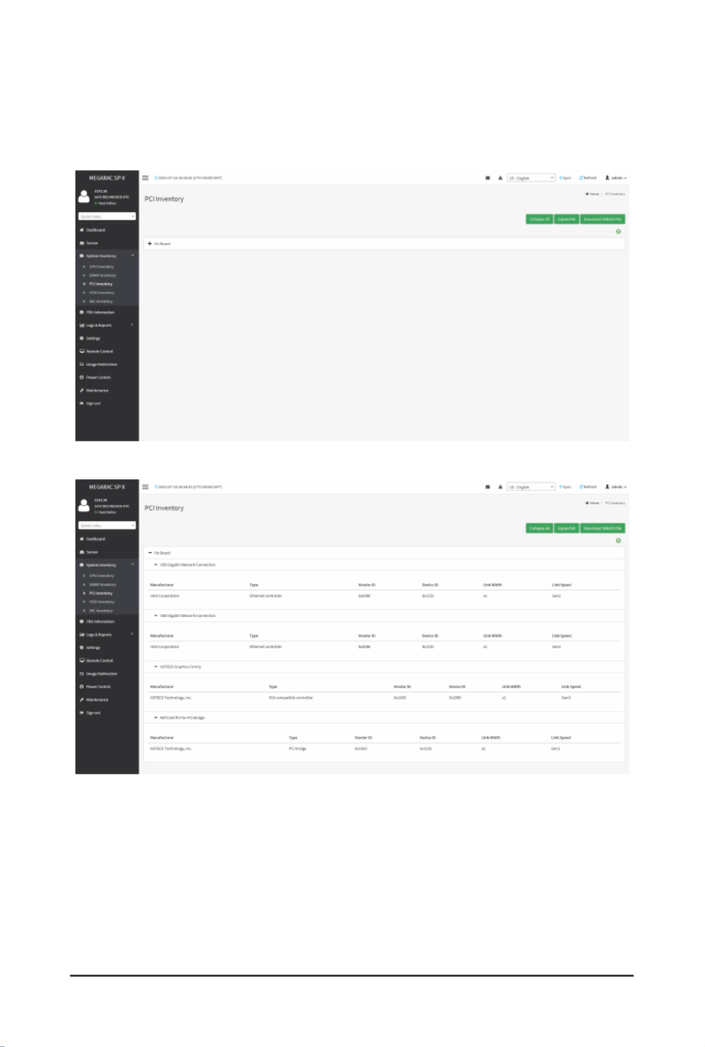
2-3-3 PCI Inventory
This page displays all detected PCI cards on this device. It allows you to see on-board PCI cards,
add-on PCI cards or all entries in detail by clicking on . Click Expand All Download SMBIOS le
todownloadtheSMBIOSle.

- 19 -
Gigabyte Server Management Console
2-3-4 HDD Inventory
This page displays all detected HDDs on this device. It allows you to see on-board HDDs, add-
on HDDs or all entries in detail by clicking on . Click Expand All Download SMBIOS file to
downloadtheSMBIOSle.
Gigabyte Server Management Console
- 20 -
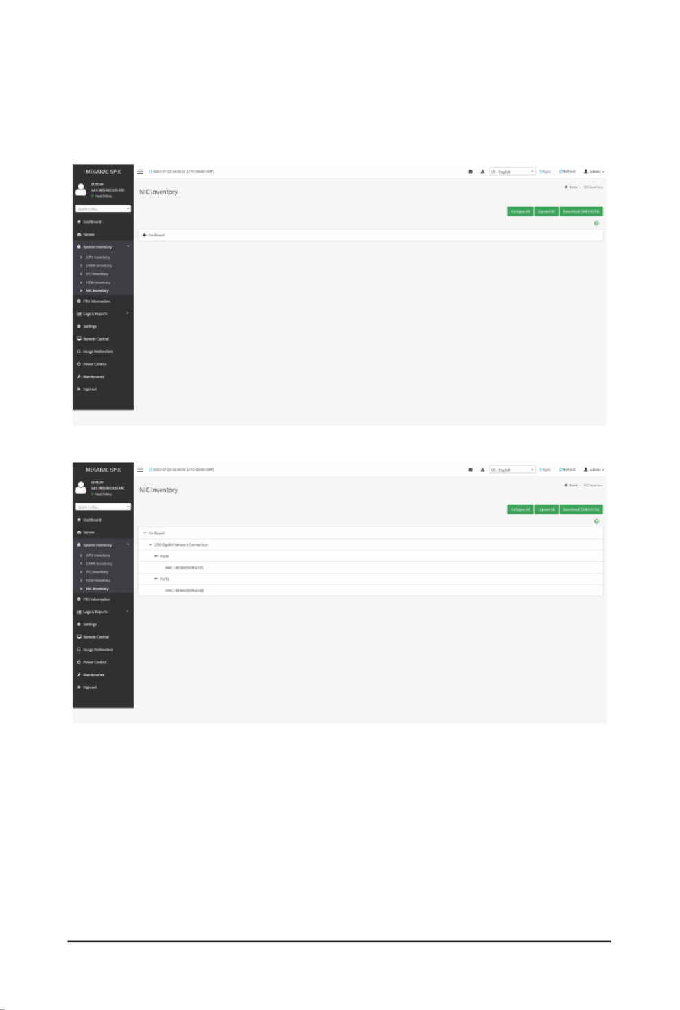
2-3-5 NIC Inventory
This page displays all detected NICs on this device. It allows you to on-board NICs, add-on NICs
or all entries in detail by clicking on . Click to download the Expand All Download SMBIOS le
SMBIOSle.

- 21 -
Gigabyte Server Management Console
2-4 FRU Information
FRU Information page displays the BMC’s FRU device information. FRU page shows information
like Basic Information, Chassis Information, Board Information and Product Information of the
FRU device.
To open the FRU Information page, click from the menu bar. Select a FRU FRU Information
Device ID from the FRU Information section to view the details of the selected device. A
screenshot of FRU Information page is shown below.
Thefollowingeldsaredisplayedherefortheselecteddevice:
Available FRU Devices
• FRU device ID - Select the device ID from the drop down list
• FRU Device Name - The device name of the selected FRU device.
Chassis Information
• Chassis Information Area Format Version
• Chassis Type
• Chassis Part Number
• Chassis Serial Number
• Chassis Extra
Board Information
• Board Information Area Format Version
• Language
• Manufacture Date Time
• Board Manufacturer
• Board Product Name
• Board Serial Number
• Board Part Number
• FRU File ID
• Board Extra

Gigabyte Server Management Console
- 22 -
Product Information
• Product Information Area Format Version
• Language
• Product Manufacturer
• Product Name
• Product Part Number
• Product Version
• Product Serial Number
• Asset Tag
• FRU File ID
• Product Extra

- 23 -
Gigabyte Server Management Console
2-5 Logs & Reports
The Logs & Reports page displays the following information:
• IPMI Event Log
• System Log
• Audit Log
• Video Log
A screenshot displaying the menu items under Logs & Reports is shown below.
A detailed description of Logs & Reports is given below.
2-5-1 IPMI Event Log
This page displays the list of event logs occurred by the different sensors on this device. Double
clickonarecordtoseethedetailsofthatentry.Youcanusethesensortypeorsensornamelter
optionstoviewthosespeciceventsoryoucanalsosortthelistofentriesbyclickingonanyof
the column headers.
To open the Event Log page, click from the menu bar.Logs & Reports > IPMI Event Log
A sample screenshot of Event Log page is shown below.

Gigabyte Server Management Console
- 24 -
TheEventLogpageconsistsofthefollowingelds:
Filter By Date Start Date End Date: Filtering can be done by selecting and .
Filter By Type: The category could be either All Events, System Event Records, OEM Event
Records, BIOS Generated Events, SMI Handler Events, System Management Software Events,
System Software - OEM Events, Remote Console software Events, Terminal Mode Remote
Console software Events.
: Once the Filter By Date and Filter type are selected, the list of events will Note
be displayed with the Event ID, Time Stamp, Sensor Type, Sensor Name and
Description.
Event Log Statistics: Displays the statistical graph for the selected date.
Clear Event Logs: Deletes all the event logs.
Download Event Logs: Downloads the event logs.
Procedure
1. using From the Filter By Dateeld,selectthetimeperiodbyStart Date End Date and
Calendar for the event categories.
2. From the Filter By Type eld,selecttheType Sensor of the event and name to view the
events for the date. The events will be displayed based on the selected time period.
3. To clear all events from the list, click .Clear All Event Logs
4. To download the event logs, click .Download Event Logs
2-5-2 System Log
To open the System Log page, click from the menu bar.Logs & Reports > System Log
A sample screenshot of System Log page is shown below.
Note:LogsmustbeconguredunderSettings > Logs Settings > Advanced Log Settings to
display any entries. Filtering options are also available for this and all logs in this section.
- 25 -
Gigabyte Server Management Console
TheSystemLogpageconsistsofthefollowingelds:
Filter By Date Start Date End Date: Filtering can be done by selecting and .
Event Category: Filters the events you want to track based on the type of event. Options include
Alert,Critical,Error,Notication,Warning,Debug,Emergency,Information.
Download Logs: Allows you to download the system logs.
Procedure
1. using From the Filter By Dateeld,selectthetimeperiodbyStart Date End Date and
Calendar for the event categories.
2. From the Event Category eld,selectthe Category of the event to view the relevant
events for the dates. The events will be displayed based on the selected time period.
3. To download the event logs, click .Download Logs
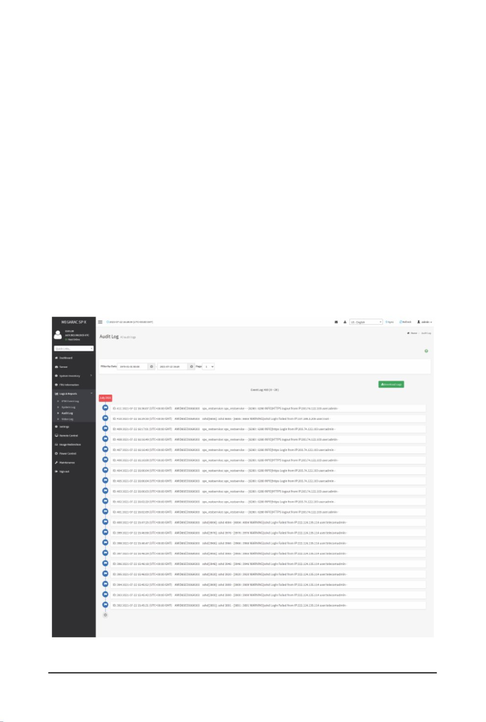
2-5-3 Audit Log
To open the Audit Log page, click Logs & Reports > Audit Log from the menu bar.
A sample screenshot of Video Log page is shown below.
Note Settings > Log Settings > Advanced Log Settings:Forconguration,goto .

- 26 -
Gigabyte Server Management Console
TheAuditLogpageconsistsofthefollowingelds:
Filter By Date Start Date End Date: Filtering can be done by selecting and .
Download Logs: Allows you to download the audit logs.
Procedure
1. using From the Filter By Dateeld,selectthetimeperiodbyStart Date End Date and
Calendar for the event categories.
2. To download the event logs, click .Download Logs
2-5-4 Video Log
To open the Video Log page, click from the menu bar.Logs & Reports > Video Log
A sample screenshot of Video Log page is shown below.
Note: Video Trigger Settings should be enabled, to display the Video Log page. Video Trigger
SettingscanbeconguredunderSettings > Video Recording > Auto Video Settings > Video
Trigger Settings.
Videowillbeallowedtoplay/downloadonlyiflesizeislesserthan40MB.Browsers
have various memory restrictions, due to this browser cannot store and process data
greaterthan40MB(approximately).Iflesizeisgreaterthan40MB,userwillbenotied
with a message to use Java player Application.

Gigabyte Server Management Console
- 27 -
2-6 Settings
This group of pages allows you to access various configuration settings. A screenshot of
CongurationGroupmenuisshownbelow.
A detailed description of the Settings menu is given below.
2-6-1 Captured BSOD
This menu is used to display a snapshot of the blue screen captured at the time when/if the host
system crashed since the last reboot. A sample screenshot of Captured BSOD is shown below.
Note: KVM service should be enabled to display the BSOD. This can be configured under
Settings > Services > KVM.

- 28 -
Gigabyte Server Management Console
2-6-2 Date & Time
ThiseldisusedtosetthedateandtimeontheBMC.AsamplescreenshotofDate&Timeis
shown below.
TheDate&Timesectionconsistsofthefollowingelds:
Configure Date & Time: Displays Time zone list containing the UTC offset along with the
locations and Navigational line to select the location which can be used to display the exact local
time.
Automatic NTP Date & Time: Automatically synchronizes Date and Time with the NTP Server.
Primary NTP Server:Congures aprimary NTPserver to use whenautomatically setting the
date and time.
Secondary NTP Server:ConguresasecondaryNTPservertousewhenautomaticallysetting
the date and time.
Save:Savestheconguredsettings.
Procedure
1. Select the Time zone location from the map.
2. Enable Automatic NTP Date & Time.

Gigabyte Server Management Console
- 29 -
3. InthePrimaryNTPServer/SecondaryNTPServereld,specifytheNTPserverforthe
device.
: Note SecondaryNTPserverisoptionaleld.IfthePrimaryNTPserverisnotworking
ne,thentheSecondaryNTPServerwillbeused.
4. Enable Automatic Date & Time option.
5. Click Save button to save the settings.
2-6-3 External User Services
LDAP/E-Directory Settings
The Lightweight Directory Access Protocol (LDAP)/E-Directory Settings is an application
protocol for querying and modifying data of directory services implemented in Internet Protocol (IP)
networks.
In Web GUI, LDAP is an Internet protocol that BMC can use to authenticate users. If you have
an LDAP server congured on your network, you can use it as an easy way to add, manage
and authenticate BMC users. This is done by passing login requests to your LDAP Server. This
meansthatthereisnoneedtodeneanadditionalauthenticationmechanism,whenusingthe
BMC. Since your existing LDAP Server keeps an authentication centralized, you will always know
whoisaccessingthenetworkresourcesandcaneasilydenetheuserorgroup-basedpolicies
to control access.
To open External User Services page, click from the menu Settings > External User Services
bar. A sample screenshot of External User Services page is shown below.
To open LDAP/E-DIRECTORY Settings page, click Settings > External User Services > LDAP/
E-Directory Settings from the menu bar.
A sample screenshot of External User Services page is shown below.

- 30 -
Gigabyte Server Management Console
TheeldsintheLDAP/E-DirectorySettingspageareexplainedbelow.
General Settings:ConguresLDAP/E-DirectorySettings.OptionsareEnableLDAP/E-Directory
Authentication, IP Address, Port and Search base.
Role Groups: Adds a new role group to the device. Alternatively, double click on a free slot to
add a role group.
Procedure
1. In the LDAP/E-Directory Settings page, click General Settings. A sample screenshot of
General LDAP Settings page is given below.
2. Click , to enable LDAP/E-Directory Settings.Enable LDAP/E-Directory Authentication
3. Select the Encryption Type for LDAP/E-Directory.
: Note Conguretheproperportnumber,whenSSLisenabled.
4. Select the Common Name Type.

Gigabyte Server Management Console
- 31 -
5. EntertheIPaddressofLDAPserverintheServerAddresseld.
: IP Address made of 4 numbers separated by dots as in ‘xxx.xxx.xxx.xxx’.Note
Each Number ranges from 0 to 255.
First Number must not be 0.
Supports IPv4 Address format and IPv6 Address format.
CongureFQDNaddress,whenusingStartTLSwithFQDN.
6. Specify the LDAP Port in the Port eld.
: Default Port is 389.Note
For SSL connections, default port is 636.
The Port value ranges from 1 to 65535.
Port 80 is blocked for TCP/UDP protocols.
7. Specify the Bind DN that is used during bind operation, which authenticates the client to
the server.
: Bind DN is a string of 4 to 63 alpha-numeric characters.Note
It must start with an alphabetical character.
Special Symbols like dot(.), comma(,), hyphen(-), underscore(_), equal-to(=) are allowed.
Example: cn=manager, ou=login, dc=domain, dc=com
8. Enter the password in the Passwordeld.
: Password must be at least 1 character long.Note
Blank space is not allowed.
Thiseldwillnotallowmorethan47characters.
9. Enter the Search Base.TheSearchbaseallowstheLDAPservertondwhichpartof
the external directory tree to be searched. The search base may be something equivalent
to the organization or the group of external directory.
: Search base is a string of 4 to 64 alpha-numeric characters.Note
It must start with an alphabetical character.
Special Symbols like dot(.), comma(,), hyphen(-), underscore(_), equal-to(=) are allowed.
Example: ou-login, dc-domain, dc-com
10. SelectAttributeofUserLogintondtheLDAP/E-Directoryserverwhichattributeshould
be used to identify the user.
: It only supports cn or uid.Note

- 32 -
Gigabyte Server Management Console
11. Select CA Certicate FilefromtheBrowseeldtoidentifythecerticateofthetrusted
CA certs.
12. Select the CA Certicate Filetondtheclientcerticatelename.
13. Select Private Keytondtheclientprivatekeylename.
: Note Allthe3lesarerequired,whenStartTLSisenabled.
14. Click Save to the settings.save
To add a new Role Group
1. In the LDAP/E-Directory Settings page, click Role Groups and select a blank row.
2. Click Add Role Group or alternatively double click on the blank row to open the Add
Role group page as shown in the screenshot below.
3. IntheGroupNameeld,enterthenamethatidentiestherolegroup.
: Role Group Name is a string of 64 alpha-numeric characters.Note
Special symbols hyphen and underscore are allowed.
4. IntheGroupDomaineld.EntertheRoleGroupDomainwheretherolegroupislocated.
: Domain Name is a string of 4 to 64 alpha-numeric characters.Note
It must start with an alphabetical character.
Special Symbols like dot(.), comma(,), hyphen(-), underscore(_), equal-to(=) are allowed.
Example: cn=manager, ou=login, dc=domain, dc=com
5. In the GroupPrivilege eld,enter thelevel ofprivilege (User,Administrator, Operator,
None) to assign to this role group.

Gigabyte Server Management Console
- 33 -
6. Select one or both of the required options
• KVM Access
• VMedia Access
7. Click to save the new role group and return to the Role Group List.Save
Active Directory Settings
An active directory is a directory structure used on Microsoft Windows based computers and
servers to store information and data about networks and domains. An active directory (sometimes
referred to as AD) does a variety of functions including the ability to provide information on
objects. It also helps to organize these objects for easy retrieval and access, allows access by
end users and administrators and allows the administrator to set security up for the directory.
ActiveDirectoryallowsyoutoconguretheActiveDirectoryServerSettings.Thedisplayedtable
showsanyconguredRoleGroupsandtheavailable slots.Youcanmodify,addordeleterole
groups from here. Group domain can be the AD domain or a trusted domain. Group Name should
correspond to the name of an actual AD group.
Note: To view the page, you must be at least a User and to modify or add a group, you must be
an Administrator.
To open Active Directory Settings page, click Settings > External User Settings > Active
Directory from the menu bar. A sample screenshot of Active Directory Settings page is shown
below.
TheeldsintheActiveDirectorypageareexplainedbelow.
General Settings: Configures Active Directory General Settings. Options are Enable Active
Directory Authentication, Secret User Name, Secret Password, User Domain Name, and up to
three Domain Controller Server Addresses.
Role Groups: Adds a new role group to the device. Alternatively, double click on a free slot to
add a role group.

- 34 -
Gigabyte Server Management Console
Procedure
Entering the details in General Active Directory Settings page:
1. Click on to open the General Active Directory Settings page.General Settings
2. In the Active Directory Settings page, check/uncheck the Enable Active Directory
Authentication check box to enable/disable Active Directory Authentication.
: If Active Directory Authentication is enabled, enter the required information Note
to access the Active Directory server.
3. Specify the Secret user name and password in the Secret User Name and Secret
Passwordeldsrespectively.
: Secret username/password for Active Directory is not mandatory. When secret Note
username & password is empty, Authentication fails will be always treated as Invalid
Password error.
For Invalid Password error PAM will not try other authentication methods. So it is
recommended to keep Active Directory in the last location in PAM order.
User Name is a string of 1 to 64 alpha-numeric characters.
It must start with an alphabetical character.
It is case-sensitive.
Special characters like comma, period, colon, semicolon, slash, backslash, square
brackets, angle brackets, pipe, equal, plus, asterisk, question mark, ampersand,
double quotes, space are not allowed.
Password must be at least 6 character long and will not allow more than 127 characters.
4. SpecifytheDomainNamefortheuserintheUserDomainNameeld.E.g.MyDomain.
com
Gigabyte Server Management Console
- 35 -
5. CongureIPaddressesinDomain Controller Server Address 1, Domain Controller
Server Address 2 and Domain Controller Server Address 3.
: IP address of Active Directory server: At least one Domain Controller Server Note
Addressmustbecongured.IPAddressmadeof4numbersseparatedbydotsasin
“xxx.xxx.xxx.xxx”.
Each number ranges from 0 to 255.
First number must not be 0.
Domain Controller Server Addresses will supports IPv4 Address format and IPv6
Address format.
6. Click Save to the entered settings and return to Active Directory Settings page.save
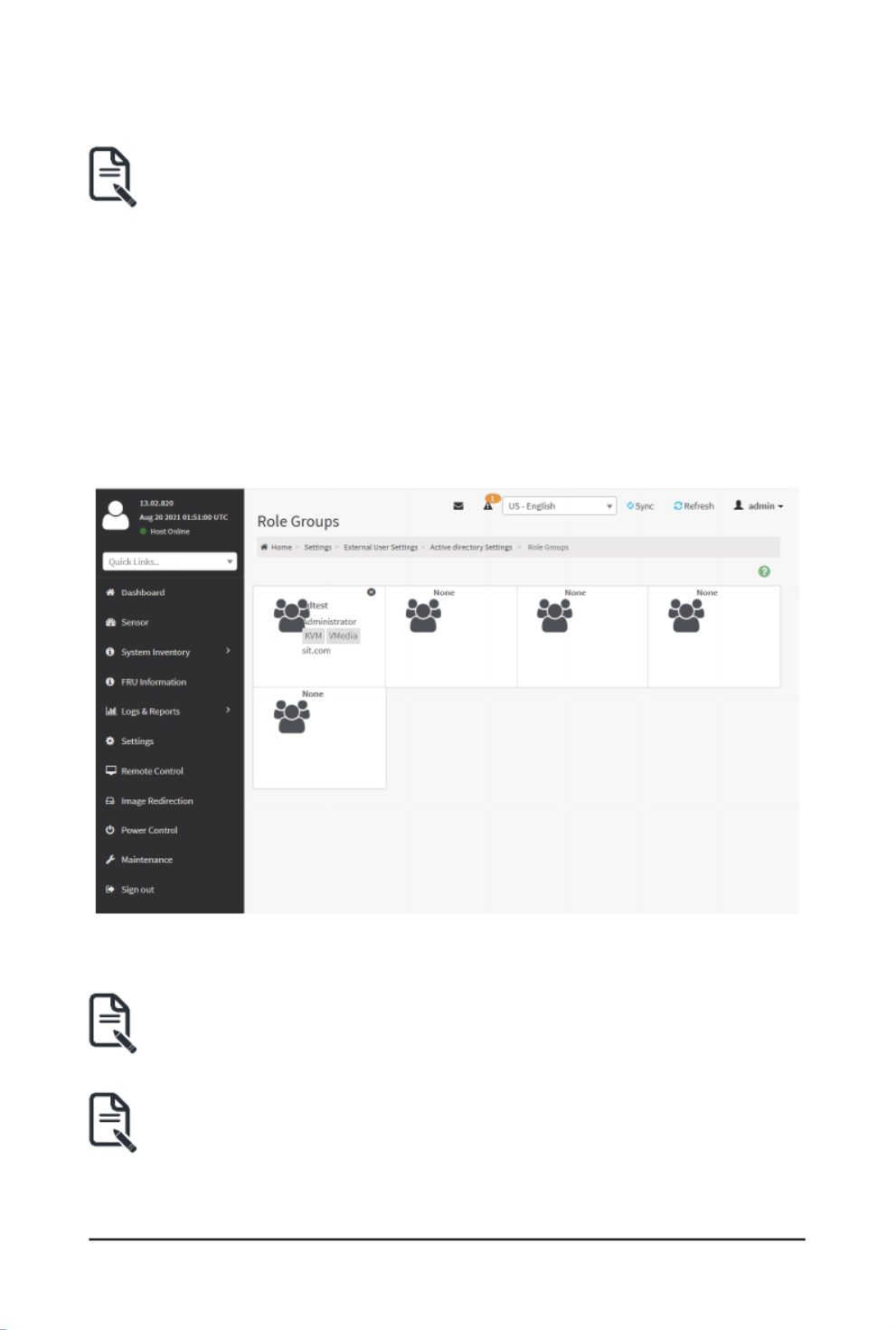
Role Groups
To open Role Group page, click Settings > External User Settings > Active Directory Settings
> Role Groups from the menu bar. A sample screenshot of Role Groups page is shown below.
TheeldsintheRoleGrouppageareexplainedbelow.
Role Group Name:ThenamethatidentiestherolegroupintheActiveDirectory.
Role Group Name is a string of 64 alpha-numeric characters.Note:
Special symbols hyphen and underscore are allowed.
Group Name:ThisnameidentiestherolegroupinActiveDirectory.
Role Group Name is a string of 64 alpha-numeric characters.Note:
Special symbols hyphen and underscore are allowed.

- 36 -
Gigabyte Server Management Console
Group Domain: The domain where the role group is located.
Domain Name is a string of 255 alpha-numeric characters.Note:
Special symbols hyphen, underscore and dot are allowed.
Group Privilege: The level of privilege to assign to this role group.
KVM Access: Provides access to KVM for AD authenticated role group user.
VMedia Access: Provides access to VMedia for AD authenticated role group user.
To add a new Role Group
1. In the Active Directory Settings page, select a Role Group and click Add Role Group or
alternatively double click on the blank row to open the Add Role group page as shown in
the screenshot below.
2. In the Group Name field, enter the name that identifies the role group in the Active
Directory.
: Role Group Name is a string of 64 alpha-numeric characters.Note
Special symbols hyphen and underscore are allowed.
3. In the Group Domaineld,enterthedomainwheretherolegroupislocated.
: Domain Name is a string of 255 alpha-numeric characters. Special symbols Note
hyphen, underscore, and dot are allowed.
4. In the Group Privilegeeld,enterthelevelofprivilegetoassigntothisrolegroup.
5. Select the required options
• KVM Access
• VMedia Access
6. Click to add the new role group and return to the Role Group List.Save

Gigabyte Server Management Console
- 37 -
To Delete a Role Group
1. In the Page, select the row that you want to delete.Role Groups
2. Click Delete Role Group.
RADIUS Settings
RADIUS is a modular, high performance and feature-rich RADIUS suite including server, clients,
development libraries and numerous additional RADIUS related utilities.
In Web GUI, this page is used to set the RADIUS Authentication.
To open RADIUS Settings page, click Settings > External User Settings > RADIUS Settings
from the menu bar. A sample screenshot of RADIUS Settings page is shown below.
TheeldsintheGeneralRADIUSSettingspageareexplainedbelow.
Enable RADIUS Authentication: Option to enable/disable RADIUS authentication.
Server Address: The IP address of RADIUS server.
: IP Address (Both IPv4 and IPv6 format).Note
FQDN(FullyQualiedDomainName)format.
Port: The RADIUS Port number.
: Default Port is 1812.Note
Port value ranges from 1 to 65535.
Port 80 is blocked for TCP/UDP protocols.
Secret: The Authentication Secret for RADIUS server.
Note:Thiseldwillnotallowmorethan32characters.
Secret must be at least 4 characters long.
Blank space is not allowed.
Enable KVM Access:ThiseldprovidesaccesstoKVMforRADIUSauthenticatedusers.
Enable VMedia Access:ThiseldprovidesaccesstoVMediaforRADIUSauthenticatedusers.
Save:Savestheconguredsettings.
- 38 -
Gigabyte Server Management Console
Procedure
1. Enable the check box to authenticate the RADIUS.RADIUS Authentication
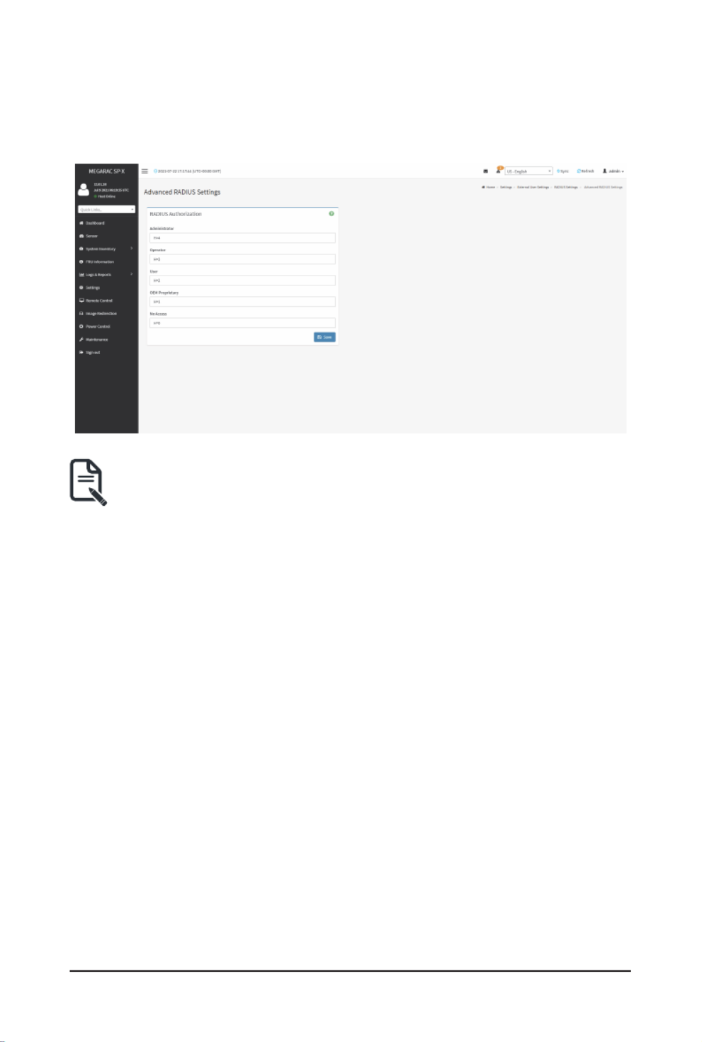
2. Click Advanced RADIUS Settings. This opens the Radius Authorization window as
shown below.
Note:ForAuthorizationPurpose,conguretheRadiususerwithVendorSpecic
Attribute on the server.
Theseeldswillnotallowmorethan127charactersandthe"#"signisnotallowed.
Example 1:
AddVendor-Specicattribute
cd/usr/share/freeradius
vim dictionary.adtest
(Add content below)
#dictionary.adtest
VENDOR ADTest 58
#Standardattribute
BEGIN-VENDOR ADTest
ATTRIBUTE ADTest-group 1 string
END-VENDOR ADTest
vim dictionary
(Add this line)
$INCLUDE dictionary.adtest
Example 2:
Add users
vim users
(add content below)
"RadiusTest1"Cleartext-Password:=“000000”
Service-Type=Administrative-User,
Auth-Type:=System,
ADTest-group:="H=4"
3. Click to save the changes made.Save

Gigabyte Server Management Console
- 39 -
2-6-4 KVM Mouse Settings
In MegaRAC GUI, Redirection Console handles mouse emulation from local window to remote
screenin eitherofthreemethods.UserhastobeanAdministratorto congurethisoption.To
view the Supported Operating Systems for Mouse Mode, click Mouse Mode.
To open KVM Mouse setting page, click from the menu bar.Settings > KVM Mouse Setting
A sample screenshot of KVM Mouse Settings page is shown below.
TheeldsintheKVMMouseSettingspageareexplainedbelow.
Relative Positioning (Linux): The relative mode sends the calculated relative mouse position
displacement to the server.
Absolute Positioning (Windows): The absolute position of the local mouse is sent to the server.
Recommended for Windows or later Linux releases.
Other Mode (SLES-11 OS Installation): Sends the calculated displacement from the local
mouse in the center position to the server.
Save: Saves the current changes.
Procedure
1. Choose either of the following as your requirement:
• Set to Absolute Positioning (Windows)
: Applicable for all Windows versions, versions above RHEL6, and versions above Note
FC14.
• Set to Relative Positioning (Linux).
: Applicable for all Linux versions, versions less than RHEL6, and versions less Note
than FC14.
• Set to Other Mode (SLES-11 OS Installation).
: Recommended for SLES-11 OS Installation.Note
2. Click button to save the changes made.Save

- 40 -
Gigabyte Server Management Console
2-6-5 Log Settings
In MegaRAC GUI, System and Audit log page displays a list of system logs and audit logs
occurred in this device.
To open the Log Settings page, click from the menu bar.Settings > Log Settings
A sample screenshot of Log Settings page is shown below.
TheeldsintheLogSettingspageareexplainedbelow.
SEL Log Settings Policy
To open SEL Log Settings Policy page, click Settings > Log Settings > SEL Log Settings
Policy fromthemenubar.TheSELLogSettingsPolicypageisusedtocongurethelogpolicy
for the event log. A sample screenshot of SEL Log Settings Policy page is shown below.

Gigabyte Server Management Console
- 41 -
Advanced Log Settings
To open Advanced Log Settings page, click Settings > Log Settings > Advanced Log Settings
from the menu bar. A sample screenshot of Advanced Log Settings page is shown below.
TheeldsintheAdvancedLogSettingspageareexplainedbelow.
System Log: Check/uncheck to enable/disable the System Logs.
Local Log: Select local log to save the logs locally (BMC).
Note:Localleresidesat/var/log/
Remote Log: Select remote log to save the logs in a remote machine.
Port Type: When Remote Log is enabled, user can select either UDP or TCP per requirement.
File Size:Thiseldistospecifythesizeoftheleinbytesiftheselectedlogtypeislocal.
Note:Sizerangesfrom3to65535.Loglesarerotatedwhentheygrowbiggerthan
size bytes mentioned, with regards for the last rotation time interval (1 minute).
Rotate Count:Backsuptheloginformationinbackuples.
: Values supported are 0 and 1.Note
Whenloginformationexceedsthelesize,theoldloginformationisautomatically
movedtobackuplesbasedontherotatecountvalue.Ifrotatecountiszero,thenold
log information gets cleared permanently.
File Size and Rotate Count options will be available only when Local Log is enabled.
Remote Log Server:Thiseldistospecifytheremoteserveraddresstologthesystemevents.
: Server address will support the following:Note
IPv4 and IPv6 address format.
FQDN(Fullyqualieddomainname)format.

- 42 -
Gigabyte Server Management Console
Remote Server Port:Thiseldistospecifytheremoteserverporttologthesystemevents.
: Remote Log Server and Remote Server Port options will be available only when Note
Remote Log is enabled.
Enable Audit Log: Enables/Disables the audit log.
Save: Saves the current changes.
Procedure
1. In the System Logeld,enableordisabletheoption.
2. Select the Log type: Local Log or Remote Log.
3. IfLocalLogisselected,enterthelesizeinthe eldandrotatecountinthFile Size
Rotate Counteld.
Note:IfRemoteLogisselected,theeldslesizeandrotatecountneednotbe
mentioned.
4. If Remote Log is selected, specify the Port Type Remote Log Server, , and Remote
Server Port.
5. In the option as needed.Audit Log Enableeld,checkoruncheckthe
6. Click to save the changes.Save

Gigabyte Server Management Console
- 43 -
2-6-6 Manage Licenses
This page displays available licenses for this system and the validity period of the licenses.
To open the Manage Licenses page, click from the menu bar.Settings > Manage Licenses
A sample screenshot of Manage Licenses page is shown below.
TheeldsintheManageLicensespageareexplainedbelow.
View Licenses: Displays the available licenses and the validity period of the licenses.
Add License Key: Select to add a license key.
2-6-7 Media Redirection Settings
ThispageisusedtocongurethemediaintoBMCforredirection.ToopentheMediaRedirect
page, click from the menu bar.Settings > Media Redirection Settings
A sample screenshot of Media Redirection page is shown below.
TheeldsintheMediaRedirectionpageareexplainedbelow.

- 44 -
Gigabyte Server Management Console
General Settings
This option is used to congure General Media Settings. To open the General Media Settings
section, click .Settings > Media Redirection Settings > General Settings
Remote Media Support: Enables/Disables Remote Media support, check/uncheck the box.
Remote Media emulates CD/DVD/HDD images as media through BMC.
Mount CD/DVD: Enables/Disables Mount CD/DVD support, check/uncheck the check box.
: You can also select all the media types simultaneously.Note
Server Address for CD/DVD Images: Displays the address of the server where the remote
media images are stored.
Path in server: Displays the source path to the remote media images.
Share Type for CD/DVD: Selects the Share Type of the remote media server either NFS, CIFS,
or HTTP.
Domain Name, Username, and Password: If share type is CIFS, then enter user credentials to
authenticate on the server.
Same settings for Harddisk Images: Enable/Disable to select same media type data
congurationsforalltheremotemediatypes.
Mount Harddisk: Enable/Disable to Mount Harddisk.
Server Address for Harddisk Images: Address of the server where the remote media images
are stored.
Path in server: Displays the source path to the remote media images.
Share Type for Harddisk: Selects the Share Type of the remote media server either NFS, CIFS,
or HTTP.
Domain Name, Username, and Password: If share type is CIFS, then enter user credentials to
authenticate on the server.
Retry Interval: Gives time interval for each attempt to reconnect Remote Media.
Retry Count:SpeciesthenumberofattemptstoreconnectRemoteMedia.

Gigabyte Server Management Console
- 45 -
Save:Savesthecongurations.
VMedia Instance Settings
This page is used to configure Virtual Media device settings. To open the VMedia Instance
Settings page, click Settings > Media Redirection Settings > VMedia Instance Settings from
the menu bar.
A sample screenshot of VMedia Instance Settings page is shown below.
Thefollowingeldsaredisplayedinthispage:
CD/DVD device instances: The number of CD/DVD devices supported for Virtual Media
redirection.
Harddisk instances: The number of hard disk devices supported for Virtual Media redirection.
Remote KVM CD/DVD device instances: The number of CD/DVD devices supported for KVM
Virtual Media redirection.
Remote KVM Hard disk instances: The number of hard disk devices supported for KVM Virtual
Media redirection.
Power Save Mode: Enables/Disables the virtual USB devices visibility in the host. If this option
is enabled, Virtual media devices will be connected to the Host machine only at the instance
launching KVM session. If this option is disabled, Virtual media devices will remain connected to
the host machine all the time irrespective of KVM session status.
Save:Savestheconguredsettings.
: Note VirtualMediacongurationchangeswillrestartallthemediaservices.So
congurationchangeswillbeblockedwhenanyactivemediaredirectionispresent.

- 46 -
Gigabyte Server Management Console
Procedure
1. Select the number of CD/DVD devices, harddisk devices and remote KVM CD/DVD and
hard disk devices from the respective drop-down list.
: Maximum of four devices can be added in CD/DVD and Harddisk drives.Note
2. Check/uncheck the option to enable/disable the virtual USB devices Power Save Mode
visibility in the host.
3. Click to save the changes made.Save
Remote Session
InMegaRAC,thispageisusedtocongureRemoteSessioncongurationsettings.KVM Single
Port Application is enabled by default.
To open the Remote Session page, click Settings > Media Redirection Settings > Remote
Session from the menu bar.
A sample screenshot of Remote Session page is shown below.
TheeldsintheCongureRemoteSessionpageareexplainedbelow.
KVM Single Port Application:Thisitemischecked(enabled)bydefaultandisnotcongurable.
The KVM session will not use its dedicated port whereas both Web and KVM sessions will be
established only via Web Port.
Keyboard Language: Select the keyboard supported languages.
Retry Count: Retries the redirection session for certain number of attempts.
Retry Time Interval (Seconds): Gives time interval for each attempt.
Server Monitor OFF Feature Status: Enables/Disables Server Monitor OFF. If this option is
enabled, you can Lock or Unlock the Local host monitor from the remote KVM window. If this
option is disabled, you cannot Lock or Unlock the Local host monitor from the remote KVM
window.

Gigabyte Server Management Console
- 47 -
Automatically OFF Server Monitor, When KVM Launches: Enables/Disables Automatically
OFF Server Monitor, When KVM Launches.
Save: Saves the current changes.
: It will automatically close the existing remote redirection either KVM or Virtual Note
media sessions on Single Port enable/disable.
: Installation of Operating System on the servers via BMC CD ISO image over Note
remote KVM may take 1 to 2 hours.
Procedure
1. Check or uncheck the KVM Single Port Application option to enable Single Port
Application support in BMC.
2. Choose the from the list of keyboard supported languages.Keyboard Language
3. Enter a value in the Retry Count eld to set the number of attempts for retrying the
redirection session.
4. Enter a value in the Retry Time Interval (Seconds)eldtogivetimeintervalforeach
attempts.
5. Check the check box to enable Local Monitor ON/Server Monitor OFF Feature Status
OFF command during runtime.
6. , Check the Automatically OFF Server Monitor When KVM Launches check box to
automatically Lock the local monitor during H5Viewer launch.
7. Click to save the current changes.Save

- 48 -
Gigabyte Server Management Console
Active Redirections
This page displays a list of Media which are being redirected currently. It shows current status
and other basic information about the Media.
2-6-8 Network Settings
The Network Settings page is used to configure the network settings for the available LAN
channels. It also allows users to manage the DNS settings or configure Network Controller
Sideband Interface of a device. To open the Network Settings page, click Settings > Network
Settings from the menu bar.

Gigabyte Server Management Console
- 49 -
Network IP Settings
To open Network IP Settings page, click Settings > Network Settings > Network IP Settings
from the menu bar. A sample screenshot of Network IP Settings page is shown below.
TheeldsintheNetworkIPSettingspageareexplainedbelow.
Enable LAN: Enables/disables the LAN Settings.
LAN Interface: Lists the LAN interfaces.
MAC Address:DisplaystheMACAddressofthedevice.Thisisareadonlyeld.
Enable IPv4: Enables/disables the IPv4 settings in the device.
Enable IPv4 DHCP: Enables IPv4 DHCP support for the selected interface.
IPv4 Address, IPv4 Subnet, IPv4 Default Gatewayand :These elds are for specifying the
staticIPv4address,SubnetMaskandDefaultGatewaytobeconguredtothedevice.
: IP Address made of 4 numbers separated by dots as in “xxx.xxx.xxx.xxx”.Note
Each Number ranges from 0 to 255.
First Number must not be 0.
Enable IPv6:Enables/disablestheIPv6congurationsettings.
Enable IPv6 DHCP:Enables/disablestheIPv6settingsinthedevice. Itdynamicallycongures
IPv6addressusingDHCP(DynamicHostCongurationProtocol).
IPv6 Index:SpeciesastaticIPv6Indextobeconguredtothedevice.E.g.:0
IPv6 Address:SpeciesastaticIPv6addresstobeconguredtothedevice.E.g.:2004::2010

- 50 -
Gigabyte Server Management Console
Subnet Prex Length:SpeciesthesubnetprexlengthfortheIPv6settings.
: Value ranges from 0 to 128.Note
IPv6 Gateway:SpeciesIPv6defaultgateway.
Note: IfcorefeatureIPV6_COMPLIANCEisenabled,theIPV6defaultGatewayeldwill
not be displayed.
Clear IPv6 Address: Check to clear the IPv6 address.
Enable VLAN: Enables/Disables the VLAN support for selected interface.
VLAN ID:TheIdenticationforVLANconguration.
: Value ranges from 1 to 4094.Note
VLANIDcannotbechangedwithoutresettingtheVLANconguration.
VLAN Priority:ThepriorityforVLANconguration.
: Value ranges from 0 to 7.Note
7 is the highest priority for VLAN.
Save: Saves the entries.
Procedure
1. Check to enable LAN support for the selected interface.Enable LAN
2. Select the LAN Interfacetobecongured.
3. Check to enable IPv4 support for the selected interface.Enable IPv4
4. Check Enable IPv4 DHCPtodynamicallycongureIPv4addressusingDHCP.
5. andIftheeldisdisabled,enterthe IPv4 Address, IPv4 Subnet IPv4 Default Gateway
intherespectiveelds.
6. .InIPv6Conguration,ifyouwanttoenabletheIPv6settings,checkEnable IPv6
7. If the IPv6 setting is enabled, enable or disable the option .Enable IPv6 DHCP
8. Iftheeldisdisabled,entertheIPv6 Index, IPv6 Address, Subnet Prex length and
IPv6 Gatewayinthegiveneld.
9. .InVLANConguration,ifyouwanttoenabletheVLANsettings,checkEnable LAN
10. Enter the VLAN IDinthespeciedeld.
11. Enter the VLAN Priorityinthespeciedeld.
12. Click to save the entries.Save

Gigabyte Server Management Console
- 51 -
Network Bond Conguration
ToopentheNetworkBondCongurationpage,clickSettings > Network Settings > Network
Bond Conguration fromthe menubar.Asample screenshotof NetworkBond Conguration
page is shown below.
TheeldsintheNetworkBondCongurationpageareexplainedbelow.
Enable Bonding: Check to enable network bonding.
: If VLAN is enabled for any slave interfaces, Bonding cannot be enabled.Note
To disable VLAN, go to .Conguration > Network > VLAN
Auto Conguration:Checktoenableautomaticcongurationofnetworkinterfaces.
Bond Interface:Conguresbondingfornetworkinterfaces.
: A minimum of two network interfaces is required to enable Network Bonding for Note
the device.
Bond Mode:Displaysthenetworkbondingmodeineffect.Thiseldisnotcongurable.
Save: Saves the entries.
Procedure
1. Check to enable network bonding for the network interfaces.Enable Bonding
2. Check to enable automatic combination of network interfaces.Auto Conguration
3. Select a bond interface.
4. Click to save the entries.Save

- 52 -
Gigabyte Server Management Console
Network Link Conguration
ToopenNetworkLinkCongurationpage,clickSettings > Network Settings > Network Link
Congurationfromthemenubar.Asamplescreenshotof NetworkLinkConguration pageis
shown below.
TheeldsintheNetworkLinkCongurationpageareexplainedbelow.
LAN Interface: Select a network interface.
Auto Negotiation: Check to enable automatic negotiation.
Link Speed:Conguresthelinkspeed.
: The link speed can be 10, 100, or 1000 Mbps.Note
Link speed of 1000 Mbps is not applicable when Auto Negotiation is disabled.
Duplex Mode: Select the duplex mode.
Note:ThissettingoptioncannotbeconguredifAutoNegotiationisenabled.
Save: Saves the entries.
Procedure
1. .SelectanetworkinterfaceyouwanttocongurefromLAN Interface
2. Check Auto Negotiationtoenableautomaticconguration.
3. Congurethelinkspeed.
Note:ThissettingoptioncannotbeconguredifAutoNegotiationisenabled.
4. Select the duplex mode.
5. Click to save the entries.Save

Gigabyte Server Management Console
- 53 -
DNS Conguration
The Domain Name System (DNS) is a distributed hierarchical naming system for computers,
services, or any resource connected to the Internet or a private network. It associates the
information with domain names assigned to each of the participants. Most importantly, it
translatesdomainnamesmeaningfultohumansintothenumerical(binary)identiersassociated
with networking equipment for the purpose of locating and addressing these devices worldwide.
The DNS Server settings page is used to manage the DNS settings of a device.
To open DNS Server Settings page, click Settings > Network Settings > DNS Conguration
fromthemenubar.AsamplescreenshotofDNSCongurationpageisshownbelow.
Domain Name Service Conguration
DNS Enabled:Enables/DisablesalltheDNSServicecongurations.
mDNS Enabled: Enables/Disables Multicast DNS.
Host Name Setting: Choose either Automatic or Manual settings.
Host Name: It displays host name of the device. If the Host setting is chosen as Manual, then
specify the host name of the device.
Value ranges from 1 to 64 alpha-numeric characters.Note:
Special characters ‘-’(hyphen) and ‘_’(underscore) are allowed. It must not start or end
with a ‘-’(hyphen). IE browsers won't work correctly if any part of the host name contain
underscore (_)character.

- 54 -
Gigabyte Server Management Console
BMC Registration Settings
BMC Interface: Options to register the BMC through the interfaces (eth0 & eth1).
Register BMC: Registers BMC through registration method.
Registration Method: Options to register the BMC are through Nsupdate or DHCP Client
FQDN Hostnameor .
TSIG Conguration
TSIG Authentication Enabled: Check this box to enable TSIG authentication while
registeringDNSviansupdate.SeparateTSIGlescanbeuploadedforeachLAN
interface.
Current TSIG Private File:TheinformationofcurrentTSIGprivatelealongwith
its uploaded date/time will be displayed (read-only).
New TSIG Private File:BrowseandnavigatetotheTSIGprivatele.
Note: TSIGleshouldbeofprivatetype.
Domain Setting
Automatic:IfyouselectAutomatic,theDomainNamecannotbeconguredasitwillbedone
automatically.Theeldwillbedisabled.
Manual: If the Domain Setting is chosen as Manual, then specify the domain name of the device.
If you select Automatic, it displays the Domain interface option. If you select Note:
Manual, it displays domain name.
Domain Name: It displays the domain name of the device.
Domain Name Server Setting
Automatic: If you select Automatic, the DNS Interface option should be explained.
Manual:SpecifytheDNS(DomainNameSystem)serveraddresstobeconguredfortheBMC.
IP Priority:
• If IP Priority is IPv4, it will have 2 IPv4 DNS servers and 1 IPv6 DNS server.
• If IP Priority is IPv6, it will have 2 IPv6 DNS servers and 1 IPv4 DNS server.
Note: ThisisnotapplicableforManualconguration.
DNS Server 1, 2 & 3
TospecifytheDNS(DomainNameSystem)serveraddresstobeconguredfortheBMC.
IPv4 Addresses should be given in dotted decimal representation.Note:
IPv6 Addresses are supported and must be global unicast addresses.
DNS Server Address will support the following:
• IPv4 Address format.
• IPv6 Address format.
Save: Saves the current changes.

- 55 -
Gigabyte Server Management Console
Procedure
1. Check the option DNS Enabled toenablealltheDNSServicecongurations.
2. Check the option to enable Multicast DNS.mDNS Enabled
3. Choose the Host Name Setting either Automatic or Manual.
If you choose Automatic, you need not enter the Host Name and if you choose Note:
Manual, you need to enter the Host Name.
4. Enter the Host NameinthegiveneldifyouhavechosenManualConguration.
5. Under Register BMC, choose the BMC’s network port to register with DNS settings.
6. Check to register with DNS settings.Register BMC
• Nsupdate - Choose Nsupdate option to register with DNS server using nsupdate
application.
• DHCP Client FQDN - Choose DHCP Client FQDN option to register with DNS
Server using DHCP option 81.
• Hostname - Choose Hostname option to register with DNS server using DHCP
option 12.
Hostname option should be selected, if the DHCP client FQDN option is not Note:
supported by DHCP server.
7. In , check TSIG Conguration TSIG Authentication Enabled enable TSIG
authentication while registering DNS via nsupdate.
• Thecurrentlenamewillbedisplayedin eld.Current TSIG Private le info
• Toviewanewone,clickNewTSIGprivateletobrowseandnavigatetotheTSI
privatele.
8. In ,Domain Settings
• Select the domain settings (Automatic or Manual).
• EntertheDomainNameinthegiveneldiftheoption.Manualisbeingselectedi
domainsettingseld.
9. In ,Domain Name Server Setting
• Select the DNS Name Server Setting (Automatic or Manual).
• Choose the IP Priority, either IPv4 or IPv6.
• Enter the DNS Server address.
10. In , DNS Server 1 DNS Server 2 DNS Server 3 and , enter the server addresses to be
conguredfortheBMC.
11. Click to save the entries.Save

Gigabyte Server Management Console
- 56 -
2-6-9 PAM Order Settings
ThispageisusedtocongurethePAMorderingforuserauthenticationintotheBMC.
To open PAM Ordering page, click Settings > PAM Order Settings from the menu bar. A sample
screenshot of PAM Order page is shown below:
TheeldsinthePAMOrderpageareexplainedbelow.
PAM Authentication Order: It shows the list of available PAM modules supported in BMC.
It is recommended to not to keep same username for different PAM modules.Note:
If Authentication fails, the reason of fail could be invalid User or Invalid Password.
If Radius Authentication fails, we can't differentiate whether it is invalid user or invalid
password. So it is always treated as Invalid username error and PAM will try other
Authentication Methods.
If AD contains secret username & password as empty, Authentication fails will be always
treated as Invalid Password error. For Invalid Password error PAM will not try other
Authentication Methods. So it is recommended to keep AD in the last location in PAM
order.
Save:Savestheconguration.
Procedure
1. Select the required PAM module and click and drag the required PAM module. It can be
moved UP or DOWN to change its arrangement order.
2. Click to save any changes made.Save
Note: Wheneverthecongurationismodied,thewebserverwillberestarted
automatically. Logged-in session will be logged out.

- 57 -
Gigabyte Server Management Console
2-6-10 Platform Event Filter
Platform Event Filter (PEF) provides a mechanism for configuring the BMC to take selected
actions on event messages that it receives or has internally generated. These actions include
operations such as system power-off, system reset, as well as triggering the generation of an
alert.
To open PEF Management Settings page, click from the menu Settings > Platform Event Filter
bar.
Event Filters
APEF implementationisrecommendedto provideatleast40 entriesinthe eventltertabl
Asubsetof theseentriesshouldbepre-congured forcommonsystemfailureevents,such as
over-temperature, power system failure, fan failure events, etc. Remaining entries can be made
available for ‘OEM’ or System Management Software configured events. Note that individual
entriescanbetaggedasbeingreservedforsystemuse-sothisratioofpre-conguredentriest
run-timecongurableentriescanbereallocatedifnecessary.

Gigabyte Server Management Console
- 58 -
The fields in the Platform Event Filters tab are explained below. This page contains pre-
congured40eventswithPEFIDs.
Procedure
1. ClicktheEventFilterssectiontoconguretheeventltersintheavailableslots.
2. To add an Event Filter entry, select a free section to open the Event Filter entry page. A
samplescreenshotofEventFilterCongurationpageisshownbelow.
IntheEventFilterCongurationsection:
• In , check this option to enable the PEF settings.Enable this lter
• In , select any one of the Event severity from the list.Event Severity to trigger
• Check Event Filter Action Alerttoenablealertsforeventlteractions.
• Select any one of the Power Action either Power down, Power reset or Power
cycle from the drop down list

- 59 -
Gigabyte Server Management Console
• ChooseanyoneoftheconguredAlert Policy Group Number from the drop down
list.
Note:AlertPolicyhastobeconguredunderSettings > PEF > Alert Policy.
• Check Raw DataoptiontolltheGeneratorIDwithrawdata.
• Generator ID 1eldisusedtogiverawgeneratorID1datavalue.
• Generator ID 2eldisusedtogiverawgeneratorID2datavalue.
Note:InRAWdataeld,specifyhexadecimalvalueprexwith‘0x'.
• In the section, choose the event generator as Slave Address - if Event Generator
event was generated from IPMB. Otherwise as System Software ID - if event was
generated from system software.
• In the Slave Address/Software IDeld,specifycorrespondingI2CSlaveAddress
or System Software ID.
• Choose the particular Channel Number that event message was received over.
Or choose ‘0’ if the event message was received via the system interface, primary
IPMB, or internally generated by the BMC.
• Choose the corresponding if event is generated by IPMB.IPMB Device LUN
• Select the Sensor typeofsensorthatwilltriggertheeventlteraction.
• In the Sensor nameeld,choosetheparticularsensorfromthesensorlist.
• Choose Event OptiontobeeitherAllEventsorSensorSpecicEvents.
• Event TriggereldisusedtogiveEvent/Readingtypevalue.
Value ranges from 0 to 255.Note:
• Event Data 1 AND Maskeldisusedtoindicatewildcardedorcomparedbits.
Value ranges from 0 to 255.Note:
• Event Data 1 Compare 1 & Event Data 1 Compare 2eldsareusedtoindicate
whether each bit position’s comparison is an exact comparison or not.
Value ranges from 0 to 255.Note:
• Event Data 2 AND MaskeldissimilartoEventData1ANDMask.
• Event Data 2 Compare 1 & Event Data 2 Compare 2eldsaresimilartoEvent
Data 1 Compare 1 and Event Data 1 Compare 2 respectively.
• Event Data 3 AND MaskeldissimilartoEventData1ANDMask.
• Event Data 3 Compare 1 & Event Data 3 Compare 2eldsaresimilartoEvent
Data 1 Compare 1 and Event Data 1 Compare 2 respectively.
3. Click Savetosavethechangesandreturntoeventlterlist.
4. Click Deletetodeletetheexistinglter.

Gigabyte Server Management Console
- 60 -
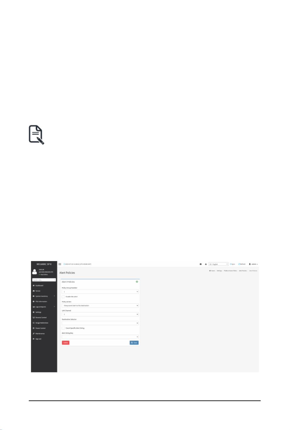
Alert Policies
ThispageisusedtoconguretheAlertPolicyforthePEFconguration.Youcanadd,deleteor
modify an entry in this page.
TheeldsintheAlertPoliciespageareexplainedbelow.
Policy Group Number:Displaysthepolicynumberoftheconguration.
Enable this alert: Enables/Disables the policy settings.
Policy Action: Chooses any one of the Policy set values (0-5) from the list.
- 61 -
Gigabyte Server Management Console
0 - Always send alert to this destination.
1 - If alert to previous destination was successful, do not send alert to this destination. Proceed to
next entry in this policy set.
2 - If alert to previous destination was successful, do not send alert to this destination. Do not
process any more entries in this policy set.
3 - If alert to previous destination was successful, do not send alert to this destination. Proceed to
next entry in this policy set that is to a different channel.
4 - If alert to previous destination was successful, do not send alert to this destination. Proceed to
next entry in this policy set that is to a different destination type.
LAN Channel: Chooses a particular channel from the available channel list.
DestinationSelector:Choosesaparticulardestinationfromthecongureddestinationlist.
Note: Settings > Platform Event Filters LANDestinationhastobeconguredunder
> LAN Destinations.
Event Specic Alert String:Speciesanevent-specicAlertString.
Alert String Key:SpecieswhichstringistobesentforthisAlertPolicyentry.
Save: Saves the Alert Policies entries.
Delete:DeletestheselectedconguredAlertPolicy.
Procedure
1. IntheAlert PoliciesSection,selecttheslotforwhichyouhaveto congure theAle
policy. That is, in the Alert Policies page, if you have chosen Alert Policy Group Number
as4,youhavetocongurethe4thslot(theslotwithPolicyNumber4)intheAlertPo
Tab.
2. Select the slot and click on the empty slot to open the Alert Policies page as shown in the
screenshot below.
3. Select from the drop-down list.Policy Group Number
4. to enable the policy settings. Check Enable this alert
Gigabyte Server Management Console
- 62 -
5. Choose any of the from the list.Policy Action
6. Choose particular from the available channel list.LAN Channel
7. In the Destination Selector, choose particular destination from the configured
destination list.
Note: Settings > Platform Event Filters LANDestinationhastobeconguredunder
> LAN Destinations.
That is if you select the number 4 for destination selector in Alert Policy Entry page, then
youhavetocongurethe4thslot(LANDestinationNumber4)intheLANDestination
tab.
8. Enable Event Specic Alert String,iftheAlertpolicyentryisEventSpecic.
9. In the Alert String Keyeld,choose anyone valuethat isused tolook uptheAlert
String to send for this Alert Policy entry.
Note: UsingWebUI,AlertstringscannotbeconguredbutoptionforEventSpecic
alert strings can be enabled/disabled. There is an option to select only the alert string
keys,butalertstringshastobeconguredusingIPMICommand(SetPEFCong
Parameter'AlertString").
10. Click to save the new alert policy and return to Alert Policy list.Save
11. Click Deletetodeleteaconguration.
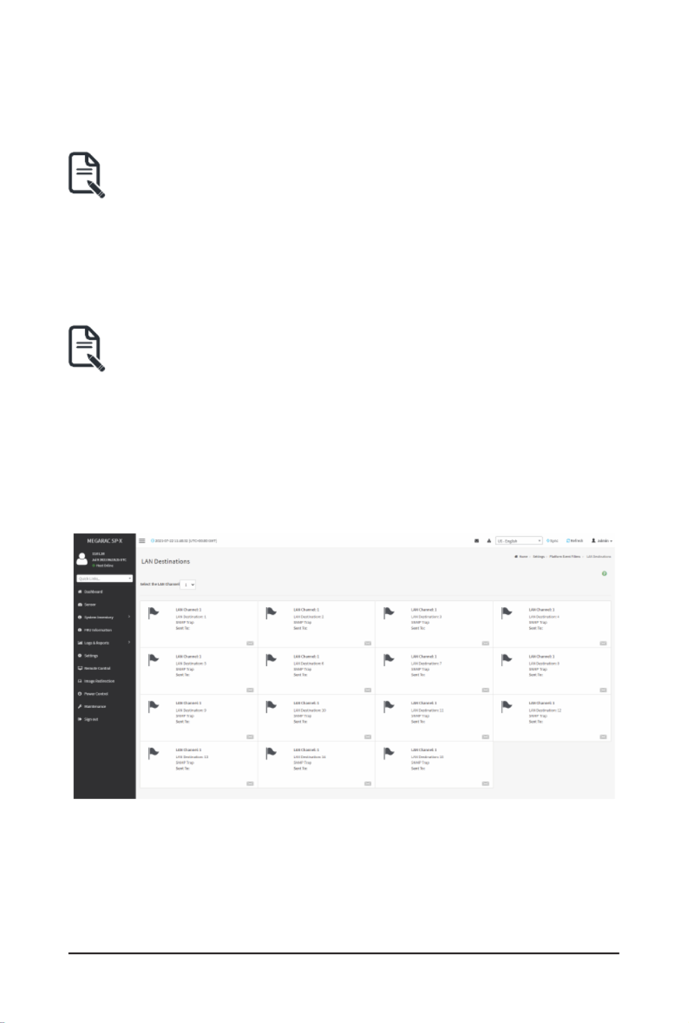
LAN Destinations
ThispageisusedtoconguretheLANdestinationofPEFconguration.
A sample screenshot of LAN Destination page is given below.
SelectanyemptyslottocongureLANDestinations.
TheeldsintheLANDestinationCongurationpageareexplainedbelow.

- 63 -
Gigabyte Server Management Console
LAN Channel: Displays LAN Channel Number for the selected slot (read-only).
LAN Destination: Displays ID for setting Destination Selector of Alert Policy (read-only).
Destination Type: Destination type can be either an SNMP Trap or an E-mail alert. For E-mail
alerts,thefourelds -SNMPDestinationAddress, BMCUserName, EmailsubjectandEm
messageneedstobelled.ForSNMPTrap,onlytheSNMPDestinationAddresshastobelled
SNMP Destination Address: If Destination type is SNMP Trap, then enter the IP address of the
system that will receive the alert. Destination address will support the following:
• IPv4 address format.
• IPv6 address format.
BMC User Name: If Destination type is Email Alert, then choose the user to whom the email
alerthastobe sent.Emailaddress fortheuserhas tobeconguredunder Settings > User
Management.
Email Subject & Email Message: Theseeldsmustbecongured ifemailalert ischosenas
destinationtype.An emailwill be sentto thecongured email addressof theuser in case
anyseverityeventswithasubjectspeciedinsubjecteldandwillcontainthemessageeld’
contentastheemailbody.Theseeldsarenotapplicablefor‘AMI-Format’emailusers.
Note Settings > User :Emailaddressfortheusershouldbeconguredunder
Management.
Save: Saves a new entry to the device.
Delete:DeletestheselectedconguredLANDestination.
Procedure
1. In the LAN Destinationspage,choosethenumberofslotstobecongured.Thisshould
be the same number of slot that you have selected in the Alert Policies - Destination
Selector field. That is if you have chosen the Destination Selector as 4 in the Alert
Policies page of Alert Policies tab, then you have to configure the 4th slot of LAN
Destination page.
2. Select the slot and click on the empty slot. This opens the .LAN Destination entry

Gigabyte Server Management Console
- 64 -
3. In the LAN Channel Numbereld,the LANChannel Numberfor theselected slotis
displayedandthisisareadonlyeld.
4. In the LAN Destinationeld,thedestinationforthenewlyconguredentryisdisplayed
andthisisareadonlyeld.
5. In the Destination Typeeld,selecttheoneofthetypes.
6. In the SNMP Destination Addresseld,enterthedestinationaddress.
7. If the destination type is Email alert, select the BMC User Name from the list of users.
.Note: Settings > User ManagementE-mailaddressshouldbeconguredunder
8. In the Email Subjecteld,enterthesubject.
9. In the Email Messageeld,enterthemessage.
10. Click Save to save the new LAN destination and return to LAN destination list.
11. Click Deletetodeleteaconguration.
12. Click Send Test Alert tosendsamplealerttocongureddestination.
Note: TestalertcanbesentonlywithenabledSMTPconguration.SMTPsupportcan
be enabled under .Settings > SMTP Settings
Gigabyte Server Management Console
- 65 -
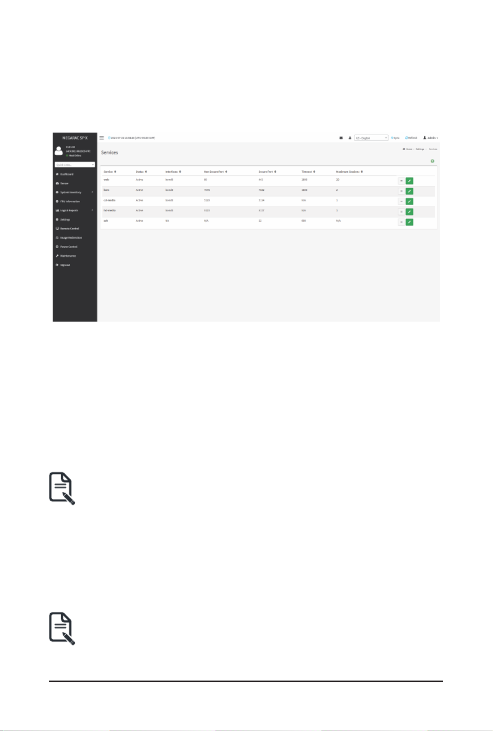
2-6-11 Services
This page displays the basic information about services running in the BMC. Only Administrator
can modify the service.
To open Services page, click from the menu bar. A sample screenshot of Settings > Services
Services page is shown below.
TheeldsintheServicespageareexplainedbelow.
Services: Displays service name of the selected slot (read-only).
Status: Displays the current status of the service, either active or inactive state.
Interfaces: It shows the interface in which service is running.
Nonsecure Port:Thisportisusedtocongurenonsecureportnumberfortheservice.
• Web default port is 80.
• KVM default port is 7578.
• CD Media default port is 5120.
• HD Media default port is 5123.
SSH service will not support non secure port. If single port feature is enabled, Note:
KVM, CD Media, and HD Media ports cannot be edited. Port value ranges
from 1 to 65535.
Secure Port:Thisportisusedtoconguresecureportnumberfortheservice.
• Web default port is 443.
• KVM default port is 7582.
• CD Media default port is 5124.
• HD Media default port is 5127.
• SSH default port is 22.
Telnet Port 80 is blocked for TCP/UDP protocols.Note:
Port value ranges from 1 to 65535.

- 66 -
Gigabyte Server Management Console
Port listening status on various feature settings:
Single port
enabled
Single port
disabled
Only KVM
encryption
enabled
Only Media
encryption
enabled
Both KVM
and Media
encryption
enabled
Adviser
(video server) 7578 (LP) 7578 (LP)
7578 (EO)
7578 (LP)
7578 (EO)
7578(LP)
7578 (EO)
7578(LP)
7582 (EO)
Cdserver 5120 (LP) 5120 (LP)
5120 (EO)
5120 (LP)
5120 (EO)
5120 (LP)
5124 (EO)
5120 (LP)
5124 (EO)
Hdserver 5123 (LP) 5123 (LP)
5123 (EO)
5123 (LP)
5123 (EO)
5123 (LP)
5127 (EO)
5123 (LP)
5127 (EO)
LP - Loopback, EO - Exposed Outside.Note:
Theadviserwillalwaysbelisteningtoloopbackaswellaskvmconguredinterface
as mentioned in the above table. So that the H5Viewer client can connect to the video
server.
Themediaserverswillbelisteningtoloopbackaswellasconguredinterfaceas
mentioned in the above table. So that the lmedia/rmedia and H5Viewer/JViewer client
can connect to the media servers.
Timeout:Displaysthe sessiontimeout valueof theservice. Users can congure the session
timeout value.
Web timeout value ranges from 300 to 1800 seconds.Note:
KVM timeout value ranges from 300 to 1800 seconds.
Web timeout value can be ignored if there is any ongoing KVM session.
SSH timeout value ranges from 60 to 1800 seconds.
Maximum Sessions: Displays the maximum number of allowed sessions for the service.
Save:Savestheconguration.
Service Sessions
The Service Sessions page is used to view the current active sessions for the service.

Gigabyte Server Management Console
- 67 -
Procedure to open Service Sessions
1. Click the View icon to view the details about the active sessions for the service.
2. This opens the Service Session screen (for example - service sessions) as shown Web
in the screenshot below.
Session ID: Displays the ID of the active sessions.
Session Type: Displays the type of the active sessions.
User ID: Displays the ID of the user.
User Name: Displays the name of the user.
Client IP:DisplaystheIPaddressesthatarealreadyconguredfortheactivesessions.
Privilege: Displays the access privilege of the user.

- 68 -
Gigabyte Server Management Console
Procedure to modify the existing services
1. SelectaslotandclickEditicontomodifythecongurationoftheservice.
Note: Wheneverthecongurationismodied,theservicewillberestartedautomatically.
User has to close the existing opened session for the service if needed.
2. This opens the screen as shown in the screenshot below.Service Conguration
3. The Service Nameledisread-only.
4. Check the check box to activate the service.Active
Note: Interfaces, Non-secure port, Secure port, Time out and Maximum Sessions will not
be active unless the current state is active.
5. Select an available interface in the Interface Name eld.
6. Enter the Non-secure Port Number in the Non-secure Porteld.
7. Enter the Secure Port Number in the Secure Porteld.

Gigabyte Server Management Console
- 69 -
8. Enter the timeout value in the Timeout eld.
The values in the Note: Maximum Sessionseldcannotbemodied.
9. Click to save all changes you have made.Save
2-6-12 SMTP Settings
Simple Mail Transfer Protocol (SMTP) is an Internet standard for electronic mail (e-mail)
transmission across Internet Protocol (IP) networks.
UsingMegaRACGUI,youcanconguretheSMTPsettingsofthedevice.
To open SMTP Settings page, click Settings > SMTP Settings from the menu bar. A sample
screenshot of SMTP Settings page is shown below.
TheeldsintheSMTPSettingspageareexplainedbelow.
LAN Interface: Displays the list of LAN channels available.
Sender Email ID: A valid ‘Sender Address’ to indicate the BMC, whenever e-mail is sent.
Primary SMTP Support: Enables/Disables SMTP support for the BMC.

- 70 -
Gigabyte Server Management Console
Primary Server Name: The ‘Machine Name’ of the BMC, from where the e-mail is sent.
Machine Name is a string of maximum 25 alpha-numeric characters.Note:
Space, special characters are not allowed.
Primary Server IP IP address: The oftheSMTPServer.Itisamandatoryeld.
IP Address made of 4 numbers separated by dots as in “xxx.xxx. xxx.xxx”.Note:
Each Number ranges from 0 to 255.
First Number must not be 0.
Supports IPv4 Address format and IPv6 Address format.
Primary SMTP Port: the SMTP Normal Port.Species
Default Port is 25, and the Port value ranges from 1 to 65535.Note:
Primary Secure SMTP Port: the SMTP Secure Port.Species
Default Port is 25, and the Port value ranges from 1 to 65535.Note:
Primary SMTP Authentication: Enables/Disables SMTP Authentication.
SMTP Server Authentication Types supported are:Note:
• CRAM-MD5
• LOGIN
• PLAIN
If the SMTP server does not support any one of the above authentication types, the user
will get an error message stating “Authentication type is not supported by SMTP
Server.”
Primary Username: Enter username to access SMTP Accounts.
User Name can be of length 4 to 64 alpha-numeric characters, dot(.), dash(-), and Note:
underline(_).
It must start with an alphabet.
Other special characters are not allowed.
Primary Password: Enter password for the SMTP User Account.
Password must be at least 4 characters long.Note:
Blank space is not allowed.
Thiseldwillnotallowmorethan64characters.
Primary SMTP SSLTLS Enable: Enables SSLTLS support for the SMTP Client.
Primary SMTP STARTTLS Enable: Enables STARTTLS support for the SMTP Client.
• Upload SMTP CA Certicate File:Filethat containsthe certicateofthe trusted
CAcerts.CACERTkeyleshouldbeofpemtype,LOGIN
• Upload SMTP Certicate File:Clientcerticatelename.CERTkeyleshouldbe
of pem type.

Gigabyte Server Management Console
- 71 -
• Upload SMTP Private Key:Clientprivatekeylename.SMTPkeyleshouldbeof
pem type.
To enable STARTTLS support, the respective SMTP support option should be Note:
enabled.
Secondary SMTP Support:It liststheSecondary SMTPServer conguration.Itisanoptional
field. If the Primary SMTP server is not working fine, then it uses Secondary SMTP Server
conguration.
Options of Secondary SMTP Support are same as Primary SMTP Support.Note:
Save:SavesthenewSMTPserverconguration.
Procedure
1. Select the from the drop-down list.LAN Interface
2. Enter the Sender Email IDinthespeciedeld.
3. Check option to enable SMTP support for the BMC.Primary SMTP Support
4. Enter the Machine Name of the SMTP Server in the .Primary Server Name
Machine Name is a string of maximum 25 alpha-numeric characters.Note:
Spaces and special characters are not allowed.
5. Enter IP address of the SMTP Server in the Primary Server IPeld.Itisamandatory
eld.
6. Enter the Primary SMTP Portinthespeciedeld.
7. Enter the Primary Secure SMTP Port inthespeciedeld.
8. Check to enable Primary SMTP Authentication if you want to authenticate SMTP
Server.
9. Enter your and Primary Username Primary Passwordintherespectiveelds.
10. Enable the check box Primary SMTP SSLTLS Enable to send data through secure Port.
If this option is selected, STARTTLS option and Normal Port will be hidden.Note:
11. Check the option to enable Secondary SMTP support for the Secondary SMTP Support
BMC.
12. Enter the Secondary Server Name, Secondary Server IP, Secondary SMTP Port and
Secondary SMTP Secure Port inthespeciedelds.
13. Check to enable Secondary SMTP Server Authentication if you want to authenticate
SMTP Server.
14. Enter your and Secondary Username Password intherespectiveelds.
15. Check to enable Secondary SMTP SSLTLS to send data through secure Port.
If this option is selected, STARTTLS option and Normal Port will be hidden.Note:
16. Click to save the entered details.Save

- 72 -
Gigabyte Server Management Console
2-6-13 SSL Settings
The Secure Socket Layer protocol was created by Netscape to ensure secure transactions
between web servers and browsers. The protocol uses a third party, a Certicate Authority (CA),
to identify one end or both end of the transactions.
Using MegaRAC GUI, configure SSL certificate into the BMC. Using this, the device can be
accessed in a secured mode.
ToopentheSSLCerticateCongurationpage,clickSettings > SSL Settings from the menu
bar. There are three tabs in this page.
TheeldsintheSSLSettingspageareexplainedbelow.
View SSL Certicate:DisplaystheuploadedSSLcerticate'sinformation.
Generate SSL Certicate:GeneratestheSSLcerticatebasedoncongurationdetails.
Upload SSL Certicate:UploadsSSLcerticateinreadableformat.

Gigabyte Server Management Console
- 73 -
View SSL Certicate
AsamplescreenshotofViewSSLCerticatepageisshownbelow.
TheeldsintheViewSSLCerticatepageareexplainedbelow.
Current Certicate Information: This section displays the basic information about the uploaded
SSLcerticate.Itdisplaysthefollowingelds:
• CerticateVersion
• Serial Number
• Signature Algorithm
• Public Key
• Issuer Common Name (CN)
• Issuer Organization (O)
• Issuer Organization Unit (OU)
• Issuer City or Locality (L)
• Issuer State or Province (ST)
• Issuer Country (C)
• Issuer E-mail Address
• Valid From

- 74 -
Gigabyte Server Management Console
• Valid Till
• Issued to Common Name (CN)
• Issued to Organization (O)
• Issued to Organization Unit (OU)
• Issued to City or Locality (L)
• Issued to State of Province (ST)
• Issued to Country (C)
• Issued to Email Address
Generate SSL Certicate
AsamplescreenshotofGenerateSSLCerticatepageisshownbelow.
TheeldsintheGenerateSSLCerticatepageareexplainedbelow.
Common Name (CN):Commonnameforwhichcerticateistobegenerated.
• Maximum length of 64 characters.
• It is a string of alpha-numeric characters.
• Specialcharacters‘#’and‘$’arenotallowed.
Organization (O):Organizationnameforwhichthecerticateistobegenerated.
• Maximum length of 64 characters.
• It is a string of alpha-numeric characters.
• Specialcharacters‘#’and‘$’arenotallowed.
Organization Unit (OU): Over all organizationsectionunit name for which certicate istob
generated.
• Maximum length of 64 characters.
• It is a string of alpha-numeric characters.
• Specialcharacters‘#’and‘$’arenotallowed.
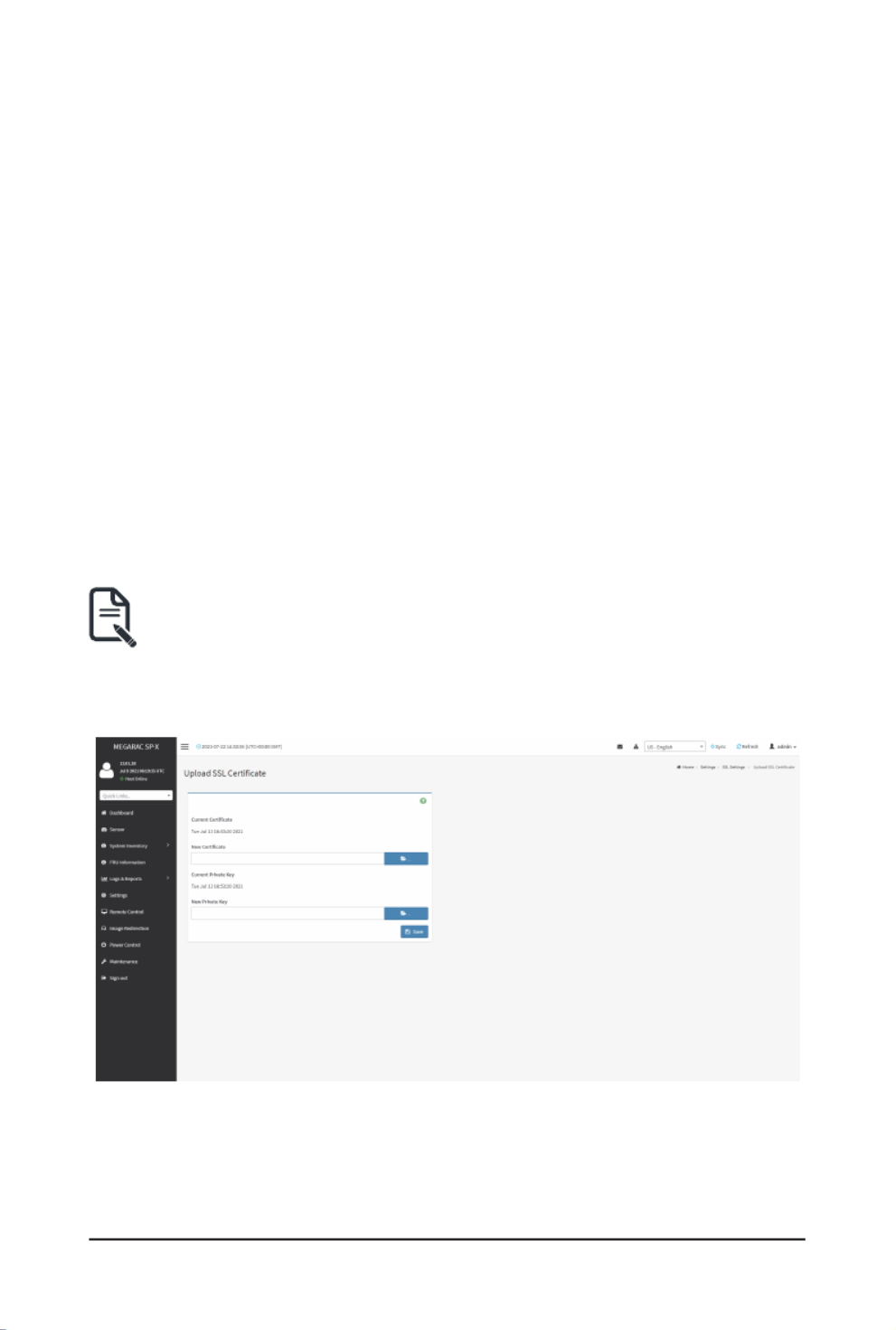
Gigabyte Server Management Console
- 75 -
City or Locality (L): City or Locality of the organization (mandatory).
• Maximum length of 128 characters.
• It is a string of alpha-numeric characters.
• Specialcharacters‘#’and‘$’arenotallowed.
State or Province (ST): State or Province of the organization (mandatory).
• Maximum length of 128 characters.
• It is a string of alpha-numeric characters.
• Specialcharacters‘#’and‘$’arenotallowed.
Country (C): Country code of the organization (mandatory).
• Only two characters are allowed.
• Special characters are not allowed.
Email Address: E-mail Address of the organization (mandatory).
Valid for:Validityofthecerticate.
• Value ranges from 1 to 3650 days.
Key Length:Thekeylengthbitvalueofthecerticate.
Save:GeneratesthenewSSLcerticate.
Note: HTTPsservicewillgetrestarted,tousethenewlygeneratedSSLcerticate.
Upload SSL Certicate
AsamplescreenshotofUploadSSLCerticatepageisshownbelow.
TheeldsintheUploadSSLCerticatepageareexplainedbelow.
Current Certicate:Currentcerticateanduploadeddate/timewillbedisplayed(read-only).
New Certicate:Browsethenewcerticatele.Thecerticateleshouldbeofpemtype.
Current Private Key: Current Private key information will be displayed (read-only).

- 76 -
Gigabyte Server Management Console
New Private Key:Browsethenewprivatekey.Theprivatekeyleshouldbeofpemtype.
Save:UploadstheSSLcerticateandprivacykeyintotheBMC.
Note: After successful upload, HTTPs service will restart to use the newly uploaded SSL
certicate.
Procedure
1. ClicktheUploadSSLCerticatetab,browsetheNewCerticateandNewPrivatekey.
2. Click Savetouploadthenewcerticateandprivatekey.
3. InGenerateSSLCerticate,enterthefollowingdetailsintherespectiveelds:
• The Common Name forwhichthecerticateistobegenerated.
• The Organizationforwhichthecerticateistobegenerated.
• The Organization Unit nameforwhichcerticatetobegenerated.
• The of the organizationCity or Locality
• The of the organizationState or Province
• The of the organizationCountry
• The of the organization.Email address
• ThenumberofdaysthecerticatewillbevalidintheValid Foreld.
4. Choose the Key Lengthbitvalueofthecerticate
5. Click Savetogeneratethecerticate.
6. Click View SSLCerticatetab to viewtheuploadedSSLcerticateinuser readable
format.
Note: OnceyouUpload/Generatethecerticates,onlyHTTPsservicewillgetrestarted.
You can now access your Web securely using the following format in your IP Address
eldfromyourInternetbrowser:https://<yourBMC'sIPaddresshere>
For example, if your BMC's IP address is 192.168.0.30, enter the following:
https://192.168.030
Pleasenotethe<s>after <http>.Youmustacceptthecerticatebeforeyouareableto
access your Web.

Gigabyte Server Management Console
- 77 -
2-6-14 System Firewall
InMegaRACGUI, theSystem Firewall pageallows you tocongure therewallsettings. T
rewallrulecanbesetforanIPorrangeofIPAddressesorPortnumbers.Toviewthispage,y
mustatleastbeanoperator.Onlyadministratorscanaddordeletearewall.
To open System Firewall page, click from the menu bar.Settings > System Firewall
General Firewall Settings
Click General Firewall Settings page. A sample screenshot of General Firewall Settings page is
shown below.

- 78 -
Gigabyte Server Management Console
TheeldsintheFirewallSettingspageareexplainedbelow.
Existing Firewall Settings
Click General Firewall Settings > Existing Firewall Settings icon. A blank page will be opened
if you did not add anything in Add Firewall Settings. If any settings are added, then the added rule
will be listed in Existing Firewall Settings page. A sample screenshot of Existing Firewall Settings
page is shown below.
The Existing Firewall Settings page allows you to remove any particular Existing Firewall
Settings.
Procedures
1. Select the Existing Firewall Settings you want to remove.
2. Click on to remove the selected Existing Firewall Settings.Delete
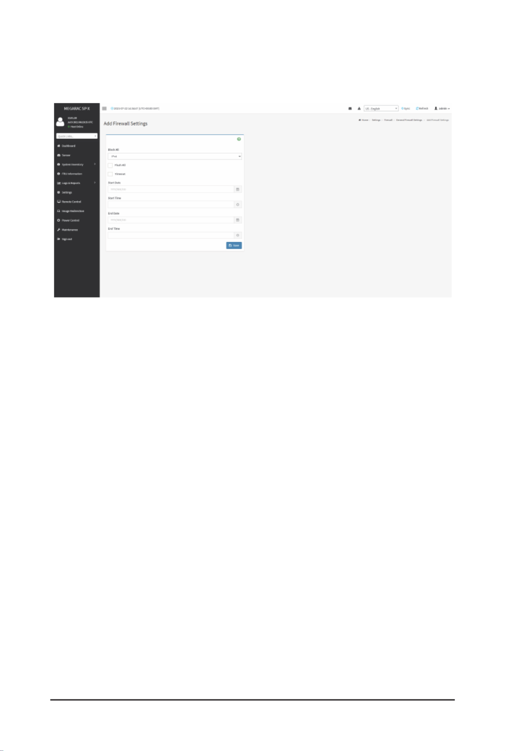
Gigabyte Server Management Console
- 79 -
Add Firewall Settings
Click General Firewall Settings > Add Firewall Settings. This opens the Add Firewall Settings
page as shown below.
Procedures
1. Select to block all the incoming IP’s and Port’s.Block All
2. Select Flush Alltoushallthesystemrewallrules.
3. Select Timeouttoenableordisablerewallruleswithtimeout.
4. Enter Start Datetostarttherespectiverewallruleeffectfromthisdate.
5. Enter Start Timetostarttherespectiverewallruleeffectfromthistime.
6. Enter End Datetoendtherespectiverewallruleeffectfromthisdate.
7. Enter End Timetoendtherespectiverewallruleeffectfromthistime.
8. Click to save the changes made.Save

- 80 -
Gigabyte Server Management Console
IP Address Firewall Rules
Click page. A sample screenshot of IP Firewall Rules page is shown below. IP Firewall Rules
TheeldsintheIPAddressFirewallpageareexplainedbelow.
Existing IP Rules
To view Existing IP Rules, click Settings > System Firewall > IP Address Firewall Rules >
Existing IP Rules. A blank page will be opened if you did not add anything in Add IP Rule. If any
rule is added, then the added rule will be listed in Existing IP Rules page.
A sample screenshot of Existing IP Rules page is shown below.
The Existing IP Rules page allows you to remove any particular Existing IP Rules.
Procedure
1. Select the Existing IP Rules you want to remove.
2. Click on to remove the selected Existing IP Rules.Delete
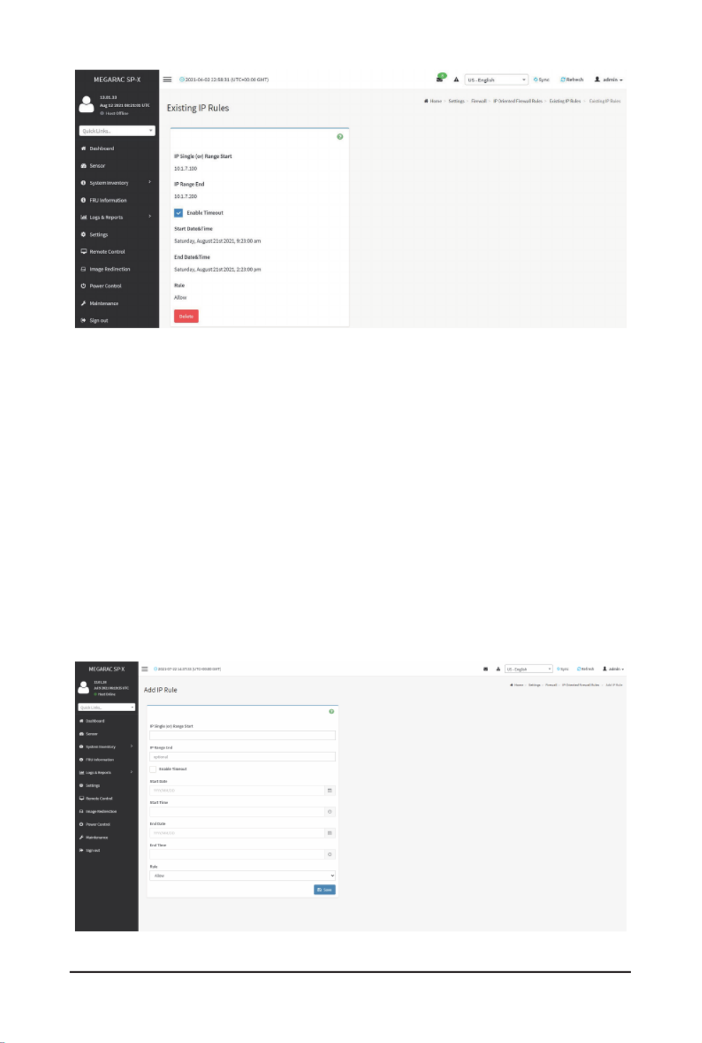
Gigabyte Server Management Console
- 81 -
IP Single (or) Range Start:ShowstheconguredPortAddressorRangeofPorts.
IP Range End:ShowstheconguredPortAddressorRangeofPorts.
Enable Timeout: Enables/Disables Timeout.
Start Date:Therespectiverewallruleeffectwillstartfromthisdate.
Start Time:Therespectiverewallruleeffectwillstartfromthistime.
End Date:Therespectiverewallruleeffectwillendfromthisdate.
End Time:Therespectiverewallruleeffectwillendfromthistime.
Rule: Indicates the current setting of the listed Port or Range of Port rules (Allow or Block) status.
Delete: Deletes the selected slot.
Add IP Rule
To add a new IP rule, click Settings > System Firewall > IP Address Firewall Rules > Add
New IP Rule. If any rule is added, then the added rule will be listed in Existing IP Rules page.
A sample screenshot of Add IP Rule page is shown below.
Procedure
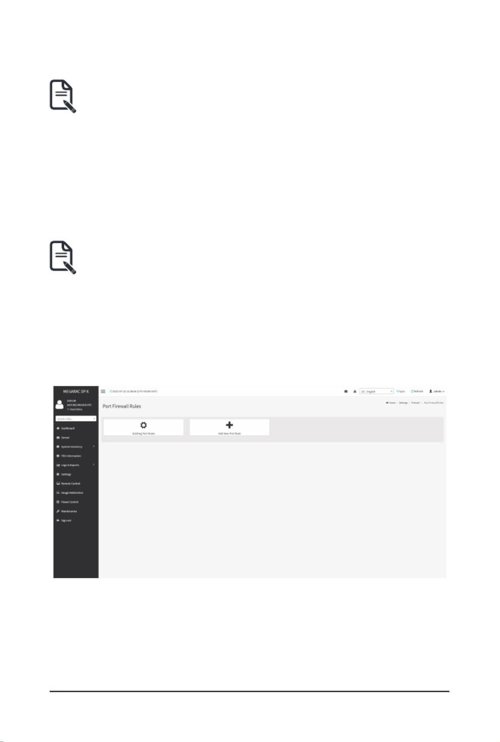
- 82 -
Gigabyte Server Management Console
1. In the Add IP Rule page, enter the IP address and a range of IP addresses in the IP
Single or IP Range Starteld.
IP Address will support IPv4 Address format only:Note:
IPv4 Address made of 4 numbers separated by dots as in xxx.xxx.xxx.xxx.
Each number ranges from 0 to 255.
First number must not be 0.
2. Enter IP range end value in the IP Range Endeld.
3. Enable Timeout toenablerewallruleswithtimeout.
4. Enter Start Date tostarttherespectiverewallruleeffectfromthisdate.
5. Enter Start Timetostarttherespectiverewallruleeffectfromthistime.
6. Enter End Date toendtherespectiverewallruleeffectfromthisdate.
7. Enter End Timetoendtherespectiverewallruleeffectfromthistime.
The date and time should be in the YYYY/MM/DD and hh-mm format respectively.Note:
8. Determine the rule to block or accept.
9. Click to save the changes made.Save
Port Firewall Rules
Click Port Firewall Rules page. A sample screenshot of Port Firewall Rules page is shown
below.
Existing Port Rules

Gigabyte Server Management Console
- 83 -
To view Existing Port Rules, click Settings > System Firewall > Port Firewall Rules > Existing
Port Rules. A blank page will be opened if you did not add anything in Add New Port Rule. If any
rule is added, then the added rule will be listed in Existing Port Rules page.
A sample screenshot of Existing Port Rules is shown below.
Procedure
1. Select the Existing Port Rules you want to remove.
2. Click on to remove the selected Existing Port Rules.Delete
TheeldsintheExistingPortRulespageareexplainedbelow.
Port Single (or) Range Start:ConguresthePortorRangeofPortAddresses.
Port Range End:ConguresthePortorRangeofPortAddresses.
Protocol:ThiseldspeciestheprotocolsfortheconguredPortorPortRanges.
Network Type: This field specifies the affected network type for the particular Port or Port

- 84 -
Gigabyte Server Management Console
Ranges.
Enable Timeout:Enables/Disablesrewallruleswithtimeout.
Start Date:Therespectiverewallruleeffectwillstartfromthistime.
Start Time:Therespectiverewallrulewillstartfromthistime.
End Date:Therespectiverewallruleeffectwillendonthisdate.
End Time:Therespectiverewallrulewillendatthistime.
Rule: Indicates Allow or Block status.
Delete:Deletestheentrytotherewallruleslist.
Add New Port Rule
To add a new port rule, click Settings > System Firewall > Port Firewall Rules > Add New
Port Rule. A sample screenshot of Add New Port Rule is shown below.
Procedure
1. In the Port Single (or) Range Start field, enter the port number or a range of port
addresses.
Port value ranges from 1 to 65535.Note:
Port 80 is blocked for TCP/UDP protocols.
2. Enter the end value in the Port Range Endeld.
3. Select the to be either TCP or UDP or Bot. Protocol
4. Select the Network Type. It may be IPv4 or IPv6 or Both.
5. Check/uncheck Enable Timeouttoenable/disablerewallruleswithtimeout.
6. Enter Start Datetostarttherespectiverewallruleeffectfromthisdate.
7. Enter Start Timetostarttherespectiverewallruleeffectfromthistime.
8. Enter End Datetoendtherespectiverewallruleeffectonthisdate.
9. Enter End Timetoendtherespectiverewallruleeffectatthistime.

Gigabyte Server Management Console
- 85 -
The time should be in the YYYY/MM/DD:hh-mm format.Note:
10. Select either or in the Block Allow Ruleeld.
11. Click to save the changes made.Save
2-6-15 User Management
In MegaRAC GUI, the User Management page allows you to view the current list of user slots for
the server. You can add a new user and modify or delete the existing users.
To open User Management page, click Settings > User Management from the menu bar. A
sample screenshot of User Management page is shown below.
TheeldsintheUserManagementpageareexplainedbelow.
The free slots are shown as “Disabled” in all columns for the slot.Note:
User ID: Displays the ID number of the user.
The list contains a maximum often users only.Note:
User Name: Displays the name of the user.
User Access: Enables/Disables the access privilege of the user.
Network Privilege: Displays the network access privilege of the user.
SNMP Status: Displays if the SNMP status for the user is enabled or Disabled.
E-mail ID: Displays e-mail address of the user.
Add User: Adds a new user.
Delete User: Deletes an existing user.
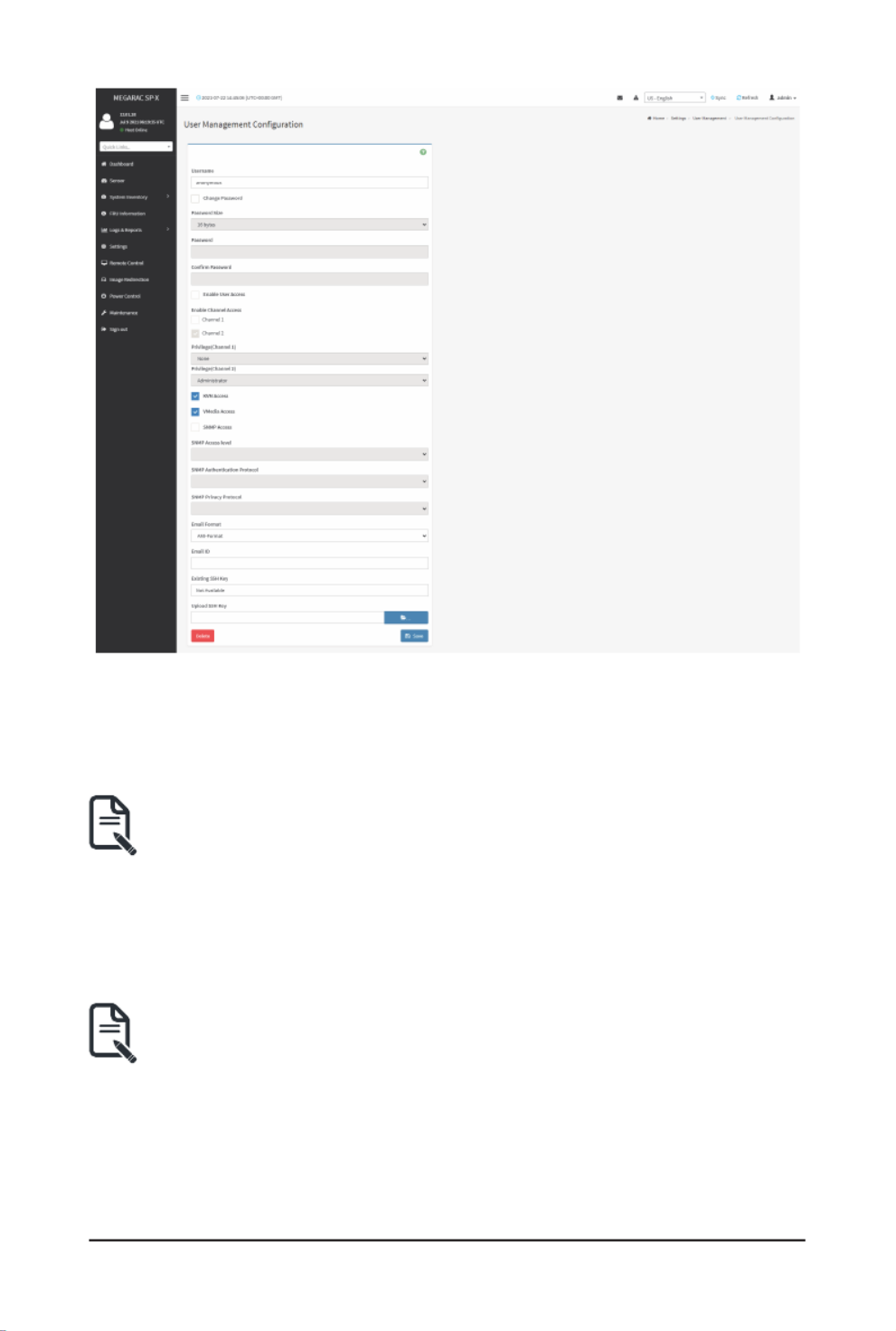
- 86 -
Gigabyte Server Management Console
Procedure
1. To add a new user, select an empty slot on the User Management page. The User
ManagementCongurationscreenwillappear,
2. Enter user name in the Usernameeld.
User name is a string of l to 16 alpha-numeric characters.Note:
It must start with an alphabetical character and it is case-sensitive.
Special characters ‘-’(hyphen), ‘_’(underscore), ‘@’(at sign) are allowed.
For 20 Bytes password, LAN session will not be established.
3. Check if you want to change the password.Change Password
4. Set for the new password.Password Size
5. In the and Password Conrm Password elds,enterandconrmthepassword.
Password should be the combination of alphabets, numbers, symbol and upper Note:
case characters.
Blank space is not allowed.
Thiseldwillnotallowmorethan16/20charactersbasedonPasswordsizeeldvalue.
Thiseldwillnotallowthebelowmentionedcharacters.
The password should be a string, if you try to set password using “ipmitool user set
password”.

Gigabyte Server Management Console
- 87 -
Hex Char
00 NUL ‘\0’
01 SOH (start of heading)
02 STX (start of text)
03 ETX (end of text)
04 EOT (end of transmission.)
05 ENQ (enquiry)
06 ACK (acknowledge)
07 BEL ‘\a’ (bell)
08 BS ‘\b’ (backspace)
09 HT ‘\t’ (horizontal lab)
0A LF ‘\n' (new Line)
0B VT ‘\v’ (vertical tab)
0C FF ‘\f’ (form feed)
0D CR ‘\r’ (carriage ret)
0E SO (shift out)
0F SI (shift in)
10 DLE (data link escape)
11 DC1 (device control 1 )
12 IDC2 (device control 2)
13 DG3 (device control 3)
14 DC4 (device control 4)
15 NAK (negative ack.)
16 SYN (synchronous idle)
17 ETB (end of trans. blk)
18 CAN (cancel)
19 EM (end of medium)
19 EM (end of medium)
1A SUB (substitute)
1B ESC (escape)
1C FS(leseparator)
1D GS (group separator)
1E RS (record separator)
1F US (unit separator)
20 SPACE
7F DEL

Gigabyte Server Management Console
- 89 -
16. The Existing SSH KeyelddisplaysinformationofanexistingSSHkey.
17. In the Upload SSH Keyeld,clickBrowseandselecttheSSHkeyle.
Note: SSHkeyleshouldbeofpubtype.
18. Click to save the new user and return to the users list.Save
If you need to modify the privilege or information of an existing user, select the user on the
UserManagementpagetoopentheUserManagementConguration screenandmodify the
congurationsaccordingly.
2-6-16 Video Recording
The Video Recording consists of the following:
1. Auto Video Settings
• Video Trigger Settings
• Video Remote Storage
• Pre-Event Video Recordings
2. SOL Settings
• SOL Trigger Settings
• SOL Video Remote Storage
• SOL Recorded Video
A sample screenshot of the Video Recording is given below.

Gigabyte Server Management Console
- 90 -
A detailed description of the menu items are given below.
Auto Video Settings
The Auto Video Settings page allows you to configure the events that will trigger auto video
recording function of the KVM server and view the current list of user slots for the server. You can
add a new user and modify or delete the existing users.
Thispage isusedto congurethe eventsthat willtrigger autovideorecording functionof t
KVM server.
To triggers for Auto Video Recording, click Video Recording > Auto Video Settings > Video
Trigger Settings from the menu bar. A sample screenshot of Video Trigger Settings page is
shown below.
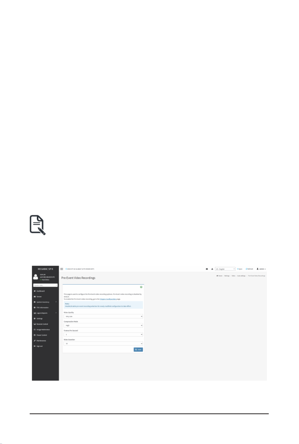
- 91 -
Gigabyte Server Management Console
Video Trigger Settings
Event List:Itshowsthelist ofavailableeventsto becongured.Theeventsare mentioned
below.
• Critical Events (Temperature/Voltage)
• Non Critical Events (Temperature/Voltage)
• Non Recoverable Events (Temperature/Voltage)
• Fan state changed Events
• Watchdog Timer Events
• Chassis Power on Events
• Chassis Power off Events
• Chassis Reset Events
• LPC Reset Events
• Date and Time Event
• Pre-Event Video Recording
Save: Saves the current changes.
Procedure
1. Check the events to be enabled.
2. To set particular date and time event, check the option Date and Time Event.
a) Choose the month, day and year from the Dateeld
b) Enter/Choose the time in hh:mm format in the Timeeld.
KVM service should be enabled to perform auto-video recording. The date and Note:
time should be in advance to the system date and time.
3. Click Pre-Event Video RecordingtoeditthePre-Eventvideorecordingcongurations.
A sample screenshot of page is shown as below.Pre-Event Video Recordings
a) To set video quality, select a resolution (Very Low, Low, Average, Normal, High)
from the drop-down list of .Video Quality

Gigabyte Server Management Console
- 92 -
b) To set compression mode, select a compression mode (high, normal, low, no) from
the drop-down list of .Compression Mode
c) To set number of frames per second, select frames/sec (1-4) from the drop-down list
of Frames Per Second.
d) To set duration of video, select second (10-60) from the drop-down list of Video
Duration.
e) Click Save to save the changes made on Pre-Event Video Recording.
4. Click to save the changes made on Video Trigger Settings.Save
Video Remote Storage
TocongureVideoRemoteStorage,clickVideo Recording > Auto Video Settings > Video
Remote Storage. A Sample screenshot of Video Remote Storage is as shown below.
Procedure
1. Check to enable the Remote Video Support.Record Video to Remote Server
Note: Bydefault,videoleswillbestoredinlocalpathofBMC.Ifremotevideosuppo
isenabled,thevideoleswillbestoredonlyinremotepath,notwithinBMC.
2. Enter Dumps value of the video in the Maximum Dumpseld.
3. Enter maximum duration of the video in the Maximum Duration (Sec)eld.
4. Enter maximum size of the video in the Maximum Size (MB)eld.
The Maximum Duration of the video should be in the range from 1 to 3600 Note:
seconds. The Maximum Size of the video should be in the range from 1 to 500 MB.
TheMaximumDumpsshouldbeintherangefrom1to100.Therecordedvideole
shouldmeeteitherthesizeconstraintordurationconstraint,accordingtothecongured
settings,dependingonwhichconstraintismetrst.

Gigabyte Server Management Console
- 93 -
5. Enter the server address in the Server Addresseld.
Server address will support the following:Note:
IP Address (Both IPv4 and IPv6 format).
FQDN(Fullyqualieddomainname)format.
6. Enter the source path in Path in Server eld
7. Select the Share Type (NFS/CIFS). If the selected share type is (CIFS), enter the
domain name, user name, and password in the Domain Name, ,Username Password
eldrespectively.
8. Click to save the settings. Save
Pre-Event Video Recording
Pre-EventVideoRecordings is usedtocongurethePre-Event videorecording options. Pre-
Event video is disabled by default. To enable the Pre-Event video recording, go to Settings >
Video Recording > Auto Video Settings > Video Trigger Settings.
Pre-Eventvideorecordingleswillbenamedaspereventcaptured.Forexample-ifanyvideo
recordedforCrashEvent,therecordedlewillbenamedaspre_crash_video_x.dat, where x is
lecount,similarlyifitisrecordedforreseteventitwillbenamedaspre_reset_video_x.dat.

Gigabyte Server Management Console
- 94 -
SOL Settings
To open SOL Set page, click from the menu bar. Settings > Video Recording > SOL Settings
A sample screenshot of SOL Settings page is shown below.
TheeldsintheSOLSettingspageareexplainedbelow.
SOL Trigger Settings
The SOL Trigger Settings page shows the list of available events.
• Critical Events (Temperature/Voltage)
• Non Critical Events (Temperature/Voltage)
• Non Recoverable Events (Temperature/Voltage)
• Fan state changed Events
• Watchdog Timer Events
• Chassis Power on Event
• Chassis Power off Event
• Chassis Reset Events
• LPC Reset Events
• Date and Time Events

- 95 -
Gigabyte Server Management Console
A sample screenshot of SOL Trigger Settings page is shown as below.
Procedure
1. ChecktheeventstobeenabledtocongurewhicheventonthepagewilltriggertheSO
video recording option to start.
2. To set particular Date and Time Event, check the option .Date and Time Event
a) Choose the month, day and year in the Dateeld.
b) Enter the in hh:mm:ss format in the Time Timeeld.
The date and time should be in advance to the system date and time.Note:
3. Click to save the changes.Save
SOL Video Settings
Thispageallowsyoutocongurerecordedvideoles.Thesamplescreenshotandvariouselds
of SOL Video Settings are given below.

Gigabyte Server Management Console
- 96 -
Procedure
1. Enter the preferred log size in the Log Size (KB)eld.Themaximumlogsizesupported
is 128 KB.
2. Enterloglecountinthe eld.Themaximumloglecountis1.Log File Count
3. Check/uncheck Record Video to Remote Server to enable/disable Remote Video
support.
Note: Bydefault,videoleswillbestoredinlocalpathofBMC.Ifremotevideosuppo
is enabled, the video will be stored only in remote path, not within BMC.
4. Enter server address in the Server Addresseld.
Server address will support the following:Note:
IP Address (Both IPv4 and IPv6 format).
FQDN(Fullyqualieddomainname)format.
5. Enter the source path in Path in Server eld.
Path must be alpha-numeric and the special characters ‘-’(hyphen), Note:
‘_’(underscore), ‘@’(at sign) are allowed.
6. Select the Share Type (NFS/CIFS). If the selected share type is (CIFS), enter the
domain name, user name, and password in the Domain Name, ,Username Password
eldrespectively.
7. Click to save the settings. Save
SOL Recorded Video
Thispagedisplaysthelistofavailablerecordedvideoles onthesystem.ClickonDownloa
icon to download and save the video. Click on icon to delete the selected video. Delete
A sample screenshot of SOL Recorded Video is given below.
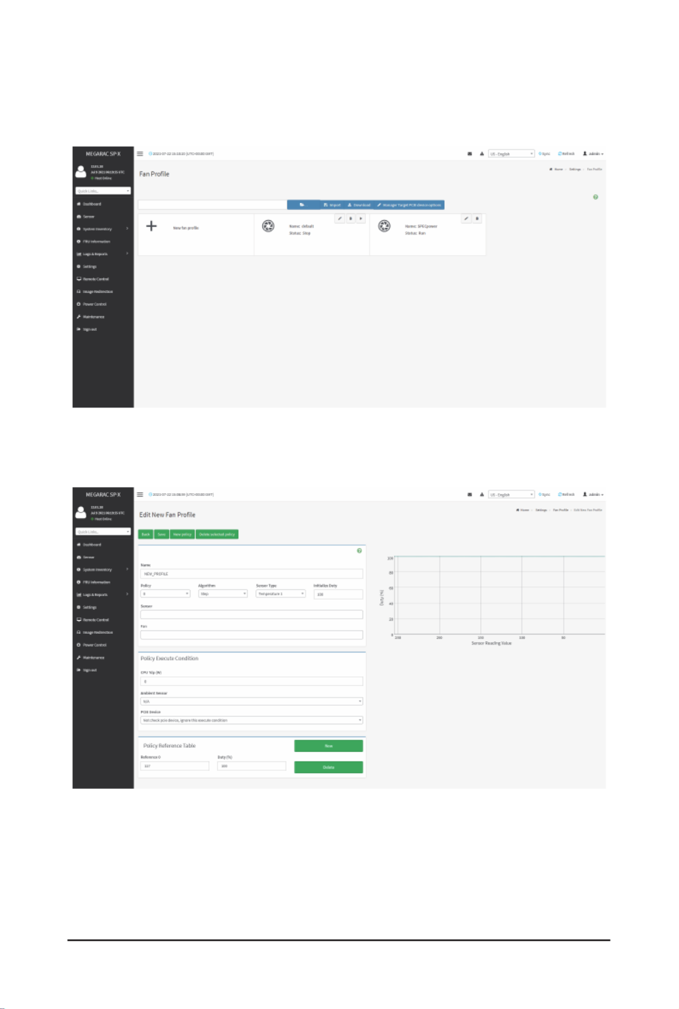
- 97 -
Gigabyte Server Management Console
2-6-17 Fan Prole
TheFanProlepageallowsyoutoaddnewfanproleoreditfanprole.
AsamplescreenshotoftheFanProleisgivenbelow.
New Fan Prole
Toaddnewfanprole,clicktheNew fan prole tab.
Procedure
1. Namethefanproleinthe eld.Name
2. Choosethemappingfunctionoftemperatureandfanspeed forthefan proleinthe
Algorithm eld.
3. Select sensory type in the Sensor Typeeld.

Gigabyte Server Management Console
- 98 -
4. Set the fan speed when the system is powering on in the Initialize Dutyeld.
5. Selectthesensoryouwanttoincludeinthisproleinthe eld.Sensor
6. Selectthefanyouwanttoincludeinthisproleinthe eld.Fan
7. Click New in the Policy Reference Tableeldtocreateanewsensorvalue&fanspeed
duty mapping table.
8. Set reference temperature and fan speed duty in the Policy Reference Tableeld.
9. Click Saveonthetopsidetosavetheconguration.
10. Clickthearrowicontorunthefanprole.
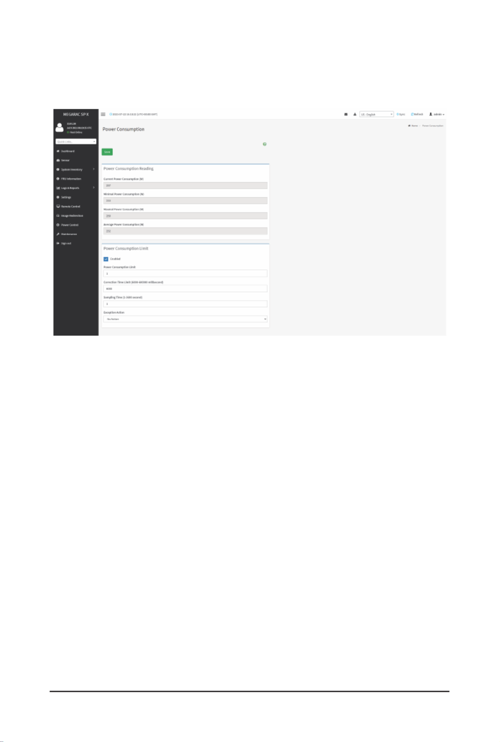
- 99 -
Gigabyte Server Management Console
2-6-18 Power Consumption
Items in displays current power consumption reading. You are Power Consumption Reading
allowedtocongurepowerlimitinthe eld.Power Consumption Limit
Procedure
1. Check to enable Power Consumption Limit.Enabled
2. Set .Power Consumption Limit
3. Set .Correction Time Limit (6000-600000 millisecond)
4. Set .Sampling Time
5. Set (No Action, Hard Power Off system and log event to SEL, Exception Action
Log event to SEL only).

- 100 -
Gigabyte Server Management Console
2-6-19 IMPI Interfaces
YouareallowedtoconguretheIPMIinterfacesinthispage.
Procedure
1. Check to enable IPMI over LAN.IPMI Over LAN
2. Check to enable IPMI over KCS.IPMI Over KCS
3. Click Savetosavetheconguration.

- 101 -
Gigabyte Server Management Console
2-6-20 RAID Management
The RAID Management page allows you to view the Storage Summary, RAID Controller
information, Physical Device Information, Logical Device Information and Event Log.
RAID Controller Information
To open the RAID Controller Information, click Settings > RAID Management > RAID Controlle
Information from the menu bar. A sample screenshot of RAID Controller Information section is
shown below.

- 102 -
Gigabyte Server Management Console
You can get RAID Controller Information only when Host is in Power ON state.Note:
Serial Number : Displays the Serial number of the RAID Controller.
Package Version : Displays the Package Version number of the RAID Controller.
BIOS Version : Displays the BIOS Version number of the RAID Controller.
UEFI Version : Displays the UEFI version number of the RAID Controller.
Expander Version : Displays the Expander Version number of the RAID Controller.
SEEPROM Version : Displays the SEEPROM Version number of the RAID Controller.
CPLD Version : Displays the CPLD Version number of the RAID Controller.
PCI Vendor Version : Displays the PCI Vendor Id of the RAID Controller.
PCI Device Version : Displays the PCI Device Id of the RAID Controller.
PCI SubVendor ID : Displays the PCI Subvendor Id of the RAID Controller.
PCI SubSystem ID : Displays the PCI Sub-Device Id of the RAID Controller.
ROC Temp (°C) : Displays ROC temperature.
Expander Temp (°C) : Displays the Expander temperature.

- 103 -
Gigabyte Server Management Console
RAID Event Log : Displays a graphical representation of all events incurred by the RAID
Controller and %occupied/available space in logs. If you click on the Details link, you can view a
list of available events.
Storage Summary
This tab displays a brief summary of storage devices available under the RAID controller. To open
the Storage Summary section, click Settings > RAID Management > Storage Summary from the
menu bar. A sample screenshot of Storage Summary section is shown below.
Physical Devices Count : Displays the number of Physical Devices connected to the controller.
Logical Devices Count:DisplaysthenumberofLogicalDevicesconguredandavailableunder
the controller.

- 104 -
Gigabyte Server Management Console
Physical Device Information
This tab displays the details about the Physical Devices connected to the RAID controller. To
open the Physical Device Information, click Settings > RAID Management > Physical Device
Information from the menu bar. A sample screenshot of Physical Device Information section is
shown below:
Select the RAID Controller:ToviewthedetailsofspecicRAIDController.
Device Id : Displays the Device ID of physical device available under selected RAID controller.
Controller : Displays the name of RAID controller to which the physical device is attached.
Media Type : Displays the media type of physical device that is attached to the selected RAID
controller.
State :DisplaysStateofthePhysicalDevice(eitheronline,orofine).
Slot : Displays Slot number, through which Physical Device is connected to the back plane.
Speed : Displays the speed of the Physical Device in Gb/s.
Link Speed : Displays the link speed of the Physical Device in Gb/s.
Size (GB) : Displays the Size of the Physical Device.
Temp (°C) : Displays the Temperature of the Physical Device.

- 105 -
Gigabyte Server Management Console
To perform additional operations, click on the slot or expand the (+) icon. A sample screenshot is
shown below.
View Physical Device Information: Click View Icon to view more details about the Physical
Device Information, including Device Id, Vendor Id, Product Id, Serial Number, Power State, and
Interface Type. A sample screenshot of View Physical Device Information page is shown below.

- 106 -
Gigabyte Server Management Console
Logical Device Information
ThistabdisplaysthedetailsabouttheLogicalDevicesconguredundertheRAIDcontroller.
open the Logical Device Information section, click Settings > RAID Management > Logical Device
Information from the menu bar. A sample screenshot of Logical Device Information section is
shown below:
Select the RAID Controller : To viewthedetailsof theLogicaldevices congured under the
specicRAIDcontroller.
LD Name:DisplaysthenameoftheLogicalDeviceconguredunderselectedRAIDcontroller
Controller : Displays the Name of the RAID Controller under which the Logical Devices are
congured.
Type:DisplaysthetypeofRAIDlevelinwhichtheLogicalDeviceiscongured,e.g.RAID
RAID 1 etc.
State:DisplaysthestateoftheLogicalDevice(eitheronlineorofine).
Read Policy : Displays the Read Policy details of the Logical Device.
Write Policy : Displays the Write Policy of the Logical Device.
Cache Policy : Displays the Cache Policy details of the Logical Device.
No. of Physical Devices:DisplaysthenumberofPhysicalDevicesavailableunderthespecic
Logical device.

- 107 -
Gigabyte Server Management Console
To perform additional operations, click on the slot or expand the (+) icon available for each
Logical Device. A sample screenshot is shown below.
View Physical Device info for selected Virtual Device : Clicking on the icon will display the
LogicalPhysicalDeviceInformationpage,Itliststheinformationofphysicaldevicescongur
forspeciedlogicaldevice.AsamplescreenshotofViewpageisshownbelow:

- 108 -
Gigabyte Server Management Console
Check Advanced Properties : Click icon to view the advanced properties of the selected Logical
device. A sample screenshot is shown below.

- 109 -
Gigabyte Server Management Console
Delete Virtual Drive : Click icon to delete selected virtual device. A pop-up message prompts
youtoconrmyourchoice.Uponconrmation,youwillbeinformedaboutthestatus.
To Create Virtual Device:
1. Click Create Virtual Device to create Logical Volume of the Device. A sample screenshot of
Create Virtual Device page is shown below.
2. Select Controller Name from the drop-down lists.
3. Select RAID Level from the drop-down lists. A sample screenshot of RAID Levels is as
shown below:
Note: Only RAID Levels RAID00,RAID10,RAID50 and RAID60 will support Span Creation.

- 110 -
Gigabyte Server Management Console
4. EnterthedepthoftheSpaninSpanDeptheld.
5. EnterthenumberofDrivesinDrivesperSpaneld.
Note:UnConguredPhysicalDrivesshouldbeequaltomultiplesofSpanDepthandDrive
per Span.
6. SelectUnCongPhysicalDrivesfromthedrop-downlists.
7. Click Create Span for mapping Span Id’s to the selected Physical Drives. The mapped
SpanId fortheselected UnconguredPhysical Driveswill bedisplayed asshownin th
above screenshot.
8. Enter Logical Name of the Device.
9. Select Initialization type from the drop-down lists.
10. Select Stripe Size (KB), Read Policy, Write Policy, IO Policy, Access Policy, Disk Cache
PolicyandUnConguredPhysicalDrivesdetailsfromtherespectivedrop-downlists.
11. Click Save to add the information to the Logical Device Information. The information will be
added and displayed in the Logical Device Information page.
To Delete Logical Device
Select the Device to be deleted and click Delete Logical Device to delete the selected logical
volume. The selected virtual device will be deleted.
Event Log
ThispagedisplaysalltheRAIDControllereventsoccurredthathasbeenalreadycongured.T
open the Event Log section, click Settings > RAID Management > Event Log from the menu bar.
Note: All the events mentioned here are read-only and cannot be edited.

- 111 -
Gigabyte Server Management Console
A sample screenshot of Event Log section is shown below:
The Event Log page consists of the following Fields.
Select the Event Type:Thiseldistolterthetypeofeventtobeviewedamongallavailable
eventsunderspeciedRAIDcontroller.ThecategorycouldbeeitherAllEvents,LDevents,PD
Events,Enclosure Events, BBU Events,SAS Events, Controller Events,Conguration Events
and Cluster Events.
Note: Filtering can be done with the Events mentioned in the list. Once the Event Log category is
chosenintheEventtypedrop-downlistthenthelteredeventswillbedisplayedwiththeRecord
ID, Time Stamp, Event Code, Event Type and Event Class.
Navigational arrows can be used to selectively access different pages of the Event Log.
Clear Event Log: To delete all the event logs.
Procedure
1. Select the RAID Controller from the drop-down list.
2. Select the Event Type from the drop-down list.
3. To clear all events from the list, click Clear Event Log.

- 112 -
Gigabyte Server Management Console
2-7 Remote Control
The system and browser requirements for Remote Control are given below.
System Requirements
• Client machine with 8GB RAM.
• If the client machine has 4GB RAM, there will be lag in Video/keyboard/mouse
functionality.
Supported Browsers
• Chrome latest version.
• IE 11 and above.
• Firefox (with limited support).
It is advisable to use Chrome or IE for H5Viewer, since Firefox has its own Note:
memory limitations.
To open the Remote Control page, click Remote Control from the menu bar. A sample
screenshot of the Remote Control page is shown below.
TheeldsintheRemoteControlpageareexplainedbelow.
H5Viewer: Launches the KVM.
JViewer:Downloadsthejviewerle.
Serial Over LAN: Launches the HTML5 Serial Over LAN window.
Identify LED:Turnson/offthechassisidenticationLED.

Gigabyte Server Management Console
- 113 -
H5Viewer
On the Remote Control page, click Launch H5Viewer. A sample screenshot of the H5Viewer
page is shown below.
Stop KVM: Stops the H5Viewer.
Video: Consists of the following items:
• Pause Video: Pauses Console Redirection.
• Resume Video: Resumes the Console Redirection when the session is paused.
• Refresh Video: Updates the display shown in the Console Redirection window.
Mouse: Contains the following items:
• Show Client Cursor: Shows or hides the local mouse cursor on the remote client
system.
• Mouse Mode: Handles mouse emulation from local window to remote screen using
eitherofthetwomethods.Only‘Administrator’hastherighttocongurethisoption.
• Absolute mouse mode: The absolute position of the local mouse is sent to the
server if this option is selected.
• Other mouse mode: Sets the client cursor in the middle of the client system and
willsendthedeviation tothehost.Thismousemode is specic for SUSE Linux
installation.
Client cursor will be hidden always. If you want to enable, use Alt + C to access Note:
the menu.

- 114 -
Gigabyte Server Management Console
Options
Zoom In / Zoom Out: Allows you to adjust zoom level.
Partial Permission / No Permission: Enables/Disables the access privilege of the user.
Auto Detect / 256 Kbps / 512 Kbps / 1 Mbps / 10 Mbps / 100 Mbps: Adjusts the bandwidth.
YUV 420 / YUV 444 / YUV 444 + 2 color VQ / YUV 444 + 4 color VQ: Adjusts the color encoding
mode.
0 Best Quality - 7: Allows you to adjust the screen resolution.
Keyboard: lists the host physical keyboard languages supported in H5Viewer.
• English U.S
• German
• Japanese
Send Keys: Enters items.
This menu contains the following sub menu items:
• Hold Down
• Press and Release
Hold Down: Contains the following items:
• Right Ctrl Key:Actsastheright-side<CTRL>keywheninConsoleRedirection.
• Right Alt Key:Actsastheright-side<ALT>keywheninConsoleRedirection.
• Right Windows Key:Actsastheright-side<WIN>keywheninConsole
Redirection.
• Left Ctrl Key:Actsastheleft-side<CTRL>keywheninConsoleRedirection.
• Left Alt Key:Actsastheleft-side<ALT>keywheninConsoleRedirection.
• Left Windows Key:Actsastheleft-side<WIN>keywheninConsoleRedirection.
You can also decide how the key should be pressed: Hold Down or Press and
Release.
Press and Release
• Ctrl+Alt+Del:Actsasifyoudepressedthe<CTRL>,<ALT>and<DEL>keysdown
simultaneously on the server that you are redirecting.
• Left Windows Key:Actsastheleft-side<WIN>keywheninConsoleRedirection.
You can also decide how the key should be pressed: Hold Down or Press and
Release.
• Right Windows Key:Actsastheright-side<WIN>keywheninConsole
Redirection.
• Context Menu Key: Acts as the context menu key, when in Console Redirection.
• Print Screen Key: Acts as the print screen key, when in Console Redirection.
Hot Keys:Addstheusercongurableshortcutkeystoinvokeinthehostmachine.
TheconguredkeyeventsaresavedintheBMC.
• AddAdd Hot Keys: Enables User Dened Macros. Click to adda UserDened
Macro.

Gigabyte Server Management Console
- 115 -
Video Record: Contains the following items:
• Record Video: Starts recording the screen.
• Stop Recording: Stops the recording.
• Record Settings: Sets Video Recording Duration.
Note: TheMaximumvideolesizeallowedisaround40MB.Ifthevideolesizereaches
itsmaxsizelimit,therecordedleisdownloadedandrecordingwillbeinprogressuntil
theconguredvideorecordingtimeisreached.Thevideoleissavedasvideo_date-
month-year_hr-min-sec_partno in client side video recording.
Usershavetotakecareofsavingthevideolesindifferentbrowsers.
When H5viewer focus is lost and if video recording is in progress, the recording will be
stoppedwithanoticationmessageandtherecordedvideolewillbediscarded.Dueto
browserlimitation,Settimeout/setintervalwillbedelayedfromspeciedtimeofinterval
when browser window loses focus, Hence, video server will not send the video packets
to H5viewer and so the video recording will be stopped.
Windows 2016 installation takes 1 hour and 52 minutes to install on Ironman Note:
through the BMC ISO redirection.
Power: Performs any power cycle operation.
• Reset Server: Reboots the system without powering off (warm boot).
• Immediate Shutdown: Turns off the server immediately.
• Orderly Shutdown: Turns off the server in proper order.
• Power ON Server: Powers on the server.
• Power Cycle Server: Performs server power control operation.
Active Users: Displays the active users and their system IP address. Active KVM Session can
be terminated when there are multiple KVM Session from Master [FULL Privilege KVM Session].
Help: Displays information about H5Viewer.
Browse File:SelectstheCDimageletoberedirectedtothehost.
Start Media:RedirectstheselectedCDimageletothehost.
Stop Media: Stops the CD media redirected to the host.
Zoom 100%: Displays the zoom level.
Host Display
• Display on: If you disable this option, the display will be shown on the screen in
Console Redirection
• Display off: If you enable this option, the server display will be blank but you can
view the screen in Console Redirection. If you disable this option, the display will be
back in the server screen.
• Capture Screen: Takes the screenshot of the host screen and save it in the client’s
system.
Power ON/OFF: Power ON/OFF the server.

- 116 -
Gigabyte Server Management Console
Procedure
1. Click to start video redirection.Launch H5Viewer
2. Click to select CD Image.Browse File
3. Click Start MediatoredirecttheselectedCDimageletotheHost.Asamplescreenshot
is as shown below.
4. To stop the CD Image redirection, click .Stop Media

Gigabyte Server Management Console
- 117 -
JViewer
JViewerallowsyoutodownloadthejviewerle.ClickLaunch JViewer to download the jviewer
le.
Note: ThejviewerleisusedforlaunchingJavaexecutablelesoverthewebor
network.
Serial Over LAN
Serial Over LAN can launch the HTML5 Serial Over LAN window. Click to launch the Activate
HTML5 Serial Over LAN window. A sample screenshot of the HTML5 Serial Over LAN window is
shown below.

- 118 -
Gigabyte Server Management Console
2-8 Images Redirection
ThispageisusedtoconguretheimagesintoBMCforredirection.Thiscanbedoneeitherby
uploading an image into BMC or by mounting the image from the remote system.
To open the Image Redirection page, click I from the menu bar. A sample mage Redirection
screenshot of the Image Redirection page is shown below.
TheeldsintheImageRedirectionpageareexplainedbelow.
Remote Images:Allowsyoutocongureimagesofremotemediaservers.
VMedia Privilege only restricts initiating / starting media redirection. If a device is Note:
already being redirected and attached to the host, then in host it will be visible as normal
device. Hence it will be accessible to all the KVM sessions. Which includes ‘KVM
Privilege only' sessions as well.

Gigabyte Server Management Console
- 119 -
2-8-1 Remote Media
TheRemoteMediatabdisplaystheconguredimagesofremotemediaserveronBMC.
Note: Morethanoneimagecanbeconguredforeachimagetype.Atmaximum4
imagescanbecongurable.
Toconguretheimage,youneedtoenableRemoteMediasupportunder
Settings > Media Redirection > General Settings.
To start/stop redirection and to delete an image, you must have Administrator Privileges.
Free slots are denoted by “~”
TheeldsintheRemoteMediapageareexplainedbelow:
Media Type: Displays type of Media such as CD/DVD and Harddisk.
Media Instance: Displays total media instance count.
Image Name: Displays the default recovery image name on the server.
Redirection Status: Displays the status of the media.
Connected Server Session Index: Displays Media Server Session Index.
Start/Stop Redirection: Starts/stops the image redirection.
Pause: Pauses the image redirection.
Refresh Image List: Gets the latest image list from the remote storage.
Sync Image Status: Synchronizes the image status.
Procedure
1. To Start/Stop Redirection andcongure remotemedia images, click(Start/Stop icon)
and make sure Remote Media Support option is enabled.
The Start Redirection button is active only for VMedia enabled users.Note:

Gigabyte Server Management Console
- 120 -
2. Selectaconguredslotandclick(Start/Stopicon)tostarttheremotemediaredirection.
It is a toggle button, if the image is successfully redirected, then click (Start/Stop icon) to
stop the remote media redirection.
Redirection needs to be stopped to clear the image.Note:
2-9 Power Control
The Power Control page allows you to view and control the power of your server.
To open the Power Control page, click from the menu bar. A sample screenshot Power Control
of Power Control is shown below.
The setting options of Power Control are explained below.
Power Off: Powers off the server immediately.
Power On: Powers on the server.
Power Cycle:Thisoptionwillrstpoweroff,andthenrebootthesystem(coldboot).
Hard Reset: This option will reboot the system without powering off (warm boot).
ACPI Shutdown: Initiates operating system shutdown prior to the shutdown.
Perform Action: Performs the selected operation.
Procedure
Select an action and click to proceed with the selected action.Perform Action
Note: DuringExecutionyouwillbeaskedtoconrmyourchoice.Uponconrmation,you
will be informed about the status after few minutes.
It is advisable to use Chrome or IE for H5Viewer, since Firefox has its own Note:
memory limitations.

- 122 -
Gigabyte Server Management Console
2-10-1 Backup Conguration
This pageallowsyoutoselectthespeciccongurationitemstobebackedupincaseof“Backup
Conguration”.
ToopentheBackupCongurationpage,clickMaintenance > Backup Conguration from the
menubar.AsamplescreenshotofBackupCongurationpageisshownbelow.
TheeldsintheBackupCongurationpageareexplainedbelow.
Check All: Selects all setting options.
Download:DownloadsandsavesthecongurationlesbackupfromBMCtoclientsystem.
Procedure
1. Click Check All to back up all setting option or check individual setting option to back up
the selected items.
2. Click Downloadtosavethebackupletotheclientsystem.

Gigabyte Server Management Console
- 123 -
2-10-2 Firmware Image Location
ThispageisusedtocongurermwareimageintotheBMC.
To open the page, click Firmware Image Location Maintenance > Firmware Image Location
from the menu bar. A sample screenshot of Firmware Image Location page is shown below.
TheeldsintheFirmwareImageLocationpageareexplainedbelow.
Image Location Type:TypeoflocationtotransferthermwareimageintotheBMCeitherWeb
Upload during Flash or TFTP Server.
TFTP Server Address:Addressoftheserverwherethermwareimageisstored.
The Server supports both IPv4 and IPv6 addressesNote:
IP Address made of 4 numbers separated by dots as in “xxx.xxx.xxx.xxx”.
Each number ranges from 0 to 255.
First number must not be 0.
IPv6 Address made of 8 groups of 4 Hexadecimal digits separated by colon as in
“xxxx:xxxx:xxxx:xxxx:xxxx:xxxx:xxxx:xxxx.”
Hexadecimal digits are expressed as lower-case letters.
TFTP Image Name: Full Sourcepath with lename of the rmwareimage is stored onTFTP
Server.
TFTP Retry Count: Number of times to be retried in case a transfer failure occurs. Retry count
ranges from 0 to 255.
Save:Savestheconguredsettings.
Procedure
1. Select the Image Location Type (Web Upload during ash / TFTP Server).
2. If the protocol selected is TFTP, enter the IP address of the server in the TFTP Server
Addresseld.
3. Enter the TFTP Image Nameinthegiveneld
4. Enter the value.TFTP Retry Count
5. Click to save the changes.Save

- 124 -
Gigabyte Server Management Console
2-10-3 Firmware Information
To open the Firmware Information page, click from the Maintenance > Firmware Information
menu bar. A sample screenshot of the Firmware Information page is shown below.
TheeldsintheFirmwareInformationpageexplainedbelow.
BMC Firmware Information
Active Image ID: Displays the active image ID.
Build Date: Displays the build date of the active BMC image.
Build Time: Displays the build time of the active BMC image.
Firmware version:DisplaysthermwareversionoftheactiveBMCimage.
BIOS Firmware Information
Product Manufacturer: Displays the hardware manufacturer.
Product Name: Displays the model name of the device.
Build Date: Displays the build date of the device.
Firmware version: Displays the BIOS version installed on the device.
CPLD Firmware Information
Firmware version: Displays the CPLD Firmware version.

Gigabyte Server Management Console
- 125 -
2-10-4 Firmware Update
To open the Firmware Update page, click from the menu bar.Maintenance > Firmware Update
The update wizard will take you through the update process. A reset of the box will automatically
follow if the upgrade is completed or cancelled. An option to Preserve All Configuration is
available;enableit,ifyouwishtopreservealreadyconguredsettingsthroughtheupgrade.
Please note that after entering the update mode wizard, other web pages Warning:
and services will not work. All open widgets will be closed automatically. If the upgrade
process is cancelled in the middle of the wizard, the device will be reset.
Note: Thermwareupgradeprocessisacrucialoperation.Makesurethatthechances
of a power or connectivity loss are minimal when performing this operation.
OnceyouenterintoUpdateModeandchoosetocancelthermwareashoperation,
the BMC must be reset. This means that you must close the Internet browser and log
back onto the BMC before you can perform any other types of operations.
Once Firmware upgrade using web is started, the regular IPMI command will not be
allowedforsafetyconcernifEnableIPMICommandhandlingduringashingsupportis
disabledinprojectconguration.
Sample screenshots of Firmware Update are shown below.
BMC Update

- 126 -
Gigabyte Server Management Console
BIOS Update
TheeldsintheFirmwareUpdatepageareexplainedbelow.
Dump BIOS: Click to dump the current BIOS image.
Choose File:Selectsthermwareimagetobeuploaded.
Note:
IfyouselectaBIOSletobeuploaded,youneedtoselectBIOS1 BIOS2 or in the
select BIOSeld.
If you select a BMC image to be uploaded, you need to select or in the Image 1 Image 2
drop-down list.
Start rmware update:Startsthermwareupdate.

Gigabyte Server Management Console
- 127 -
Procedure
1. Click Select Firmware Imagetoselectthermwareimagetobeuploaded.
2. Click to proceed.Start rmware update
3. Click Preserve all Conguration ifyouwanttopreserveallcongurationsettingsduring
thermwareupdateandthenclickProceed to Flash at the bottom to proceed.
Termékspecifikációk
| Márka: | Gigabyte |
| Kategória: | szerver |
| Modell: | R282-NO0 |
Szüksége van segítségre?
Ha segítségre van szüksége Gigabyte R282-NO0, tegyen fel kérdést alább, és más felhasználók válaszolnak Önnek
Útmutatók szerver Gigabyte

16 December 2024
11 Október 2024
6 Október 2024
29 Augusztus 2024
29 Augusztus 2024
29 Augusztus 2024
29 Augusztus 2024
29 Augusztus 2024
29 Augusztus 2024
29 Augusztus 2024
Útmutatók szerver
- szerver Sony
- szerver Fujitsu
- szerver Acer
- szerver StarTech.com
- szerver Lenovo
- szerver Toshiba
- szerver HP
- szerver Medion
- szerver Vimar
- szerver Technics
- szerver Rocstor
- szerver Digitus
- szerver TRENDnet
- szerver Dell
- szerver Tripp Lite
- szerver Conceptronic
- szerver Blackmagic Design
- szerver Hikvision
- szerver Netgear
- szerver Asus
- szerver ELAC
- szerver Synology
- szerver Supermicro
- szerver ZyXEL
- szerver Smart-AVI
- szerver Planet
- szerver Ernitec
- szerver Black Box
- szerver MSI
- szerver Cisco
- szerver ATen
- szerver APC
- szerver SEH
- szerver Western Digital
- szerver HGST
- szerver D-Link
- szerver Monacor
- szerver Moxa
- szerver Abus
- szerver Veritas
- szerver Atlona
- szerver Lindy
- szerver Areca
- szerver QNAP
- szerver NEC
- szerver Siig
- szerver Eaton
- szerver Gefen
- szerver Kathrein
- szerver IStarUSA
- szerver Lantronix
- szerver Provision-ISR
- szerver Axis
- szerver NETSCOUT
- szerver Sitecom
- szerver ACTi
- szerver Megasat
- szerver KanexPro
- szerver Kramer
- szerver Allnet
- szerver SilverStone
- szerver Maxdata
- szerver AVerMedia
- szerver Matrox
- szerver Flir
- szerver Buffalo
- szerver GeoVision
- szerver LevelOne
- szerver LaCie
- szerver Valcom
- szerver Asustor
- szerver Intel
- szerver Fantec
- szerver Freecom
- szerver Seagate
- szerver Iomega
- szerver Digi
- szerver Revox
- szerver Luxman
- szerver Ibm
- szerver Sonnet
- szerver TAIDEN
- szerver Advantech
- szerver Extron
- szerver Avocent
- szerver Intellinet
- szerver Teradek
- szerver Silex
- szerver Hanwha
- szerver In Win
- szerver Sun
- szerver MvixUSA
- szerver Dual Bay
- szerver Raidsonic
- szerver EMC
- szerver Infortrend
- szerver Opengear
- szerver G-Technology
- szerver EXSYS
- szerver Chenbro Micom
- szerver Middle Atlantic
- szerver Mr. Signal
- szerver Atlantis Land
- szerver C2G
- szerver Promise Technology
- szerver Mobotix
- szerver Origin Storage
Legújabb útmutatók szerver

9 Április 2025
3 Április 2025

2 Április 2025
29 Március 2025
29 Március 2025
29 Március 2025
24 Március 2025
24 Március 2025

15 Január 2025
15 Január 2025