Használati útmutató Gigabyte R180-F2A
Olvassa el alább 📖 a magyar nyelvű használati útmutatót Gigabyte R180-F2A (119 oldal) a szerver kategóriában. Ezt az útmutatót 2 ember találta hasznosnak és 2 felhasználó értékelte átlagosan 4.5 csillagra
Oldal 1/119

R180-F2A
Dual LGA2011 sockets R3 motherboard for Intel ®
E5-2600 V3/V4 series processors
Service Guide
Rev. 1.0

Copyright
© 2016 GIGA-BYTE TECHNOLOGY CO., LTD. All rights reserved.
The trademarks mentioned in this manual are legally registered to their respective owners.
Disclaimer
Information in this manual is protected by copyright laws and is the property of GIGABYTE.
Changes to the specifications and features in this manual may be made by GIGABYTE
without prior notice. No part of this manual may be reproduced, copied, translated, transmitted, or
published in any form or by any means without GIGABYTE's prior written permission.
Documentation Classications
In order to assist in the use of this product, GIGABYTE provides the following types of documentations:
For detailed product information, carefully read the User's Manual.
For more information, visit our website at:
http://b2b.gigabyte.com
You are a professional?
Get an access to our complete source of sales, marketing & technical materials at:
http://reseller.b2b.gigabyte.com
Join our server forum to discuss our products and get technical assistance at:
forum.b2b.gigabyte.com
https://www.facebook.com/gigabyteserver

Preface
Before using this information and the product it supports, please read the following general infor-
mation.
1. -This Service Guide provides you with all technical information relating to the BASIC CON
FIGURATION decided for GIGABYTE’s “global” product offering. To better t local market-
requirements and enhance product competitiveness, your regional ofce MAY have decided
toextend the functionality of a machine (e.g. add-on card, modem, or extra memory capabil-
ity).These LOCALIZED FEATURES will NOT be covered in this generic service guide. In
suchcases, please contact your regional ofces or the responsible personnel/channel to
provide youwith further technical details.
2. Please note WHEN ORDERING SPARE PARTS, you should check the most up-to-date
informationavailable on your regional web or channel. For whatever reason, if a part num-
ber change is made,it will not be noted in the printed Service Guide. For GIGABYTE-AU-
THORIZED SERVICEPROVIDERS, your GIGABYTE ofce may have a DIFFERENT part
number code to thosegiven in the FRU list of this printed Service Guide. You MUST use the
list provided by yourregional GIGABYTE ofce to order FRU parts for repair and service of
customer machines.

- 4 -
Table of Contents
Box Contents 7
...................................................................................................................
Safety, Care and Regulatory Information 8
........................................................................
Chapter 1 Hardware Installation ...................................................................................
11
1-1 Installation Precautions ..................................................................................
11
1-2 Product Specications ....................................................................................
12
1-3 System Block Diagram 14
...................................................................................
Chapter 2 System Hardware Installation 15
......................................................................
2-1 Removing Chassis Cover 16
...............................................................................
2-2 Removing and Installing the Fan Duct 17
...........................................................
2-3 Installing the CPU 18
.........................................................................................
2-4 Installing the Heat Sink 19
.................................................................................
2-5 Installing the Memory 20
.....................................................................................
2-5-1 Four Channel Memory Conguration .....................................................................
20
2-5-2 Installing a Memory 21 ...............................................................................................
2-5-3 DIMM Population Table ..........................................................................................
21
2-6 Installing the PCI Expansion Card 22
.................................................................
2-6-1 Installing Add-on Card (Optional) 23 ...........................................................................
2-7 Installing the Hard Disk Drive 24
.........................................................................
2-8 Replacing the FAN Assemblly 25
........................................................................
2-9 Replacing the Power Supply 26
..........................................................................
2-10 Installing Rail Into A Rack 27
...............................................................................
Chapter 3 System Appearance .....................................................................................
28
3-1 Front View 28
......................................................................................................
3-2 Rear View 28
.......................................................................................................
3-3 Front Panel LED and Buttons 29
........................................................................
3-4 Rear System LAN LEDs 30
.................................................................................
3-5 Hard Disk Drive LEDs 31
....................................................................................
3-6 Cable Routing 32
................................................................................................
Chapter 4 Motherboard Components 33
...........................................................................
4-1 MD90-FS0 Motherboard Components 33
...........................................................
4-2 Jumper Setting 36
..............................................................................................
Chapter 5 BIOS Setup 37
..................................................................................................

- 5 -
5-1 The Main Menu 39
..............................................................................................
5-2 Advanced Menu 42
.............................................................................................
5-2-1 Serial Port Console Redirection 43 .............................................................................
5-2-2 PCI Subsystem Settings 46 .........................................................................................
5-2-2-1 PCI Express Settings 48 ..............................................................................................
5-2-3 Network Stack 50 ........................................................................................................
5-2-4 CSM Conguration .................................................................................................
51
5-2-5 Post Report Conguration ......................................................................................
53
5-2-6 Trusted Computing 54 .................................................................................................
5-2-7 USB Conguration ..................................................................................................
55
5-2-8 Chipset Conguration .............................................................................................
56
5-9 SIO Conguration ...................................................................................................
57
5-2-10 iSCSI Conguration ................................................................................................
59
5-3 Intel RC Setup Menu 60
......................................................................................
5-3-1 Processor Conguration .........................................................................................
61
5-3-1-1 Pre-Socket Conguration .......................................................................................
64
5-3-2 Advanced Power Management Conguration ........................................................
66
5-3-2-1 CPU P State Control 67 ...............................................................................................
5-3-2-2 CPU C State Control 68 ..............................................................................................
5-3-2-3 CPU T State Control 69 ...............................................................................................
5-3-3 Common RefCode Conguration ...........................................................................
70
5-3-4 QPI Conguration ...................................................................................................
71
5-3-5 Memory Conguration ............................................................................................
73
5-3-5-1 Memory Topology ...................................................................................................
75
5-3-5-2 Memory Thermal ....................................................................................................
76
5-3-5-3 Memory Map 77 ...........................................................................................................
5-3-5-4 Memory RAS Conguration ....................................................................................
78
5-3-6 IIO Conguration ....................................................................................................
79
5-3-6-1 IOAT Conguration .................................................................................................
80
5-3-6-2 Intel VT for Directed I/O (VT-d) ..............................................................................
81
5-3-7 PCH Conguration .................................................................................................
82
5-3-7-1 PCH Devices 83 ..........................................................................................................
5-3-7-2 PCH sSATA Conguration ......................................................................................
84
5-3-7-2-1 SATA Mode Options 87 ..............................................................................................
5-3-7-3 PCH SATA Conguration ........................................................................................
89
5-3-7-3-1 SATA Mode Options 92 ..............................................................................................
5-3-7-4 USB Conguration ..................................................................................................
94
5-3-8 Miscellaneous Conguration ..................................................................................
95
5-3-9 Server ME Conguration ........................................................................................
96
5-3-10 Runtime Error Logging 97 ...........................................................................................
5-3-10-1 Whea Setting ..........................................................................................................
98
5-3-10-2 Memory Error Enabling 99 ...........................................................................................

- 8 -
Safety, Care and Regulatory Information
Important safety information
Read and follow all instructions marked on the product and in the documentation before you operateyour sys-
tem. Retain all safety and operating instructions for future use.
• The product should be operated only from the type of power source indicated on the rating label.* If your
computer has a voltage selector switch, make sure that the switch is in the proper position foryour area.
The voltage selector switch is set at the factory to the correct voltage.
• The plug-socket combination must be accessible at all times because it serves as the main disconnect-
ing device.
• All product shipped with a three-wire electrical grounding-type plug only fits into a grounding-type
poweroutlet. This is a safety feature. The equipment grounding should be in accordance with local and
nationalelectrical codes. The equipment operates safely when it is used in accordance with its marked
electricalratings and product usage instructions
• Do not use this product near water or a heat source.* Set up the product on a stable work surface or so
as to ensure stability of the system.
• Openings in the case are provided for ventilation. Do not block or cover these openings. Make sure
youprovide adequate space around the system for ventilation when you set up your work area. Never
insertobjects of any kind into the ventilation openings.
• To avoid electrical shock, always unplug all power cables and modem cables from the wall outletsbefore
removing covers.
• Allow the product to cool before removing covers or touching internal components.
Precaution for Product with Laser Devices
Observe the following precautions for laser devices:
• Do not open the CD-ROM drive, make adjustments, or perform procedures on a laser device other than
those specied in the product's documentation.
• Only authorized service technicians should repair laser devices.
Precaution for Product with Modems, Telecommunications, ot Local AreaNetwork Options
Observe the following precautions for laser devices:
• Do not connect or use a modem or telephone during a lightning storm. There may be a risk of electri-
calshock from lightning.
• To reduce the risk of re, use only No. 26 AWG or larger telecommunications line cord.
• Do not plug a modem or telephone cable into the network interface controller (NIC) receptacle.
• Disconnect the modem cable before opening a product enclosure, touching or installing internalcompo-
nents, or touching an uninsulated modem cable or jack.
• Do not use a telephone line to report a gas leak while you are in the vicinity of the leak.

- 9 -
Federal Communications Commission (FCC) Statement
Warning
This is a class A product. In a domestic environment this product may cause radiointerfer-
enceIn which case the user may be required to take adequate measures.
This equipment has been tested and found to comply with the limits for a Class A digital device,pursuant to
Part 15 of the FCC Rules. These limits are designed to provide reasonable protection againstharmful interfer-
ence when the equipment is operated in a commercial environment. This equipmentgenerates, uses, and can
radiate radio frequency energy and, if not installed and used in accordance withthe instruction manual, may
cause harmful interference to radio communications. Operation of thisequipment in a residential area is likely
to cause harmful interference in which case the user will berequired to correct the interference at his own ex-
pense.Properly shielded and grounded cables and connectors must be used in order to meet FCC emission-
limits. Neither the provider nor the manufacturer are responsible for any radio or television interferencecaused
by using other than recommended cables and connectors or by unauthorized changes ormodications to this
equipment. Unauthorized changes or modications could void the user's authority tooperate the equipment.
This device complies with Part 15 of the FCC Rules. Operation is subject to the following two conditions:
(1) this device may not cause harmful interference, and
(2) this device must accept any interference received, including interference that may cause undesired opera-
tion.
Canadian Department of Communications Compliance Statement
This digital apparatus does not exceed the Class A limits for radio noise emissions from digitalapparatus as
set out in the radio interference regulations of Industry Canada.Le present appareil numerique n'emet pas
de bruits radioelectriques depassant les limites applicables auxappareils numeriques de Classe A prescrites
dans le reglement sur le brouillage radioelectrique edicte parIndustrie Canada.
Class A equipment
This device has been tested and found to comply with the limits for a class A digital device pursuantPart 15 of
the FCC Rules. These limits are designed to provide reasonable protection againstharmful interference when
the equipment is operated in a commercial environment. This equipmentgenerate, uses, and can radiate
radio frequency energy, and if not installed and used in accordancewith the instructions, may cause harmful
interference to radio communication. Operation of thisequipment in a residential area is likely to cause harm-
ful interference, in which case the user will berequired to correct the interference at personal expence.
However, there is no guarantee that interference will not occur in a particular installation. If thisdevice does
cause harmful interference to radio or television reception, which can be determined bytuning the device off
and on, the user is encouraged to try to correct the interference by on or more ofthe following measures:
• Reorient or relocate the receiving antenna
• Increase the separation between the device and receiver
• Connect the device into an outlet on a circuit different from that to which the receiver isconnected'Consult
the dealer or an experienced radio/television technician for help.

- 10 -
Battery Warning: Incorrectly installing a battery or using incompatible battery may increase
the risk of ifre explosion. Replace the battery only with the same or equivalent type.
• Do not disassemble, crush, punchture batteries.
• Do not store or place your battery pack next to or in a heat source such as a re, heatgenerating
appliance, can or exhaust vent. Heating battery cells to temperatures above 65oC (149oF) can
cause explosion or re.
• -Do not attempt to open or service batteries. Do not dispose of batteries in a re or with house
hold waste.
WEEE Symbol Statement
The symbol shown below is on the product or on its packaging, which indicates that this product
must not be disposed of with other waste. Instead, the device should be taken to the waste
collection centers for activation of the treatment, collection, recycling and disposal procedure.
The separate collection and recycling of your waste equipment at the time of disposal will help to
conserve natural resources and ensure that it is recycled in a manner that protects human health
and the environment. For more information about where you can drop off your waste equipment for recycling,
please contact your local government ofce, your household waste disposal service or where you purchased
the product for details of environmentally safe recycling.
w When your electrical or electronic equipment is no longer useful to you, "take it back" to your local or
regional waste collection administration for recycling.
w If you need further assistance in recycling, reusing in your "end of life" product, you may contact us at the
Customer Care number listed in your product's user's manual and we will be glad to help you with your
effort.
California Proposition 65
Warning:
This product contains a chemical, including lead , known to the State of California to cause cancer
http://www.p65warnings.ca.gov/
Warning:
This product contains a chemical, including lead , known to the State of California to cause birth defects or
other reproductive harm.
http://www.p65warnings.ca.gov/

- 11 - Hardware Installation
1-1 Installation Precautions
The motherboard/system contain numerous delicate electronic circuits and components which
can become damaged as a result of electrostatic discharge (ESD). Prior to installation, carefully
read the service guide and follow these procedures:
• Prior to installation, do not remove or break motherboard S/N (Serial Number) sticker or
warranty sticker provided by your dealer. These stickers are required for warranty validation.
• Always remove the AC power by unplugging the power cord from the power outlet before
installing or removing the motherboard or other hardware components.
• When connecting hardware components to the internal connectors on the motherboard,
make sure they are connected tightly and securely.
When handling the motherboard, avoid touching any metal leads or connectors.•
• It is best to wear an electrostatic discharge (ESD) wrist strap when handling electronic
components such as a motherboard, CPU or memory. If you do not have an ESD wrist
strap, keep your hands dry and rst touch a metal object to eliminate static electricity.
•
Prior to installing the motherboard, please have it on top of an antistatic pad or within an
electrostatic shielding container.
• Before unplugging the power supply cable from the motherboard, make sure the power
supply has been turned off.
• Before turning on the power, make sure the power supply voltage has been set according to
the local voltage standard.
• Before using the product, please verify that all cables and power connectors of your
hardware components are connected.
• To prevent damage to the motherboard, do not allow screws to come in contact with the
motherboard circuit or its components.
• Make sure there are no leftover screws or metal components placed on the motherboard or
within the computer casing.
Do not place the computer system on an uneven surface•
.
Do not place the computer system in a high-temperature environment.•
• Turning on the computer power during the installation process can lead to damage to
system components as well as physical harm to the user.
• If you are uncertain about any installation steps or have a problem related to the use of the
product, please consult a certied computer technician.
Chapter 1 Hardware Installation

Hardware Installation - 12 -
1-2 Product Specications
CPU wSupport for Intel® Xeon® E5-2600 V3/V4 series processors in the LGA2011
package
wL3 cache varies with CPU
wSupports Dual QuickPath Interconnect up to 9.6GT/s
w
Enhanced Intel SpeedStep Technology (EIST)
w
Support Intel Virtualization Technology (VT)
Chipset wIntel® C612 Express (Wellsburg) Chipset
Memory w24 x DIMM slots
wDDR4 memory supported only
wQuad channel memory architecture
wECC RDIMM / LRDIMM modules supported
wSingle and dual rank RDIMM modules up to 32GB supported
w3DS LRDIMM modules up to 128GB supported
w
1.2V modules: 1600/1866/2133/2400 MHz
LAN wIntel® I350 supports dual GbE LAN ports
Expansion Slot w2 x PCIe x16 slots (Gen3 x16 bus)
w1 x PCIe p12-x8 slot (Gen3 p12-x8 bus)
w1 x PCIe mezzanine type T (Gen3 x8 bus) slot
Onboard
Graphics wASPEED® AST2400 supports 16MB DDR3 VRAM
Mass Storage w8 x 2.5” Hot-Swap HDDs
System Fans w4 x 40x40x28mm /18000rpm
w4 x 40x40x56mm/23000rpm
USB w2 x USB 3.0 ports
w2 x USB 2.0 ports
Internal
Connectors
w1 x 14-pin ATX main power connector
w3 x 8-pin ATX power connectors
w3 x 4-pin ATX 12V power connectors
w2 x hot-plug power supply connectors
w
2 x Mini-SAS connectors (SATA3 6Gb/s signal)
w2 x SATA3 6Gb/s connectors
w2 x CPU fan headers
w5 x System fan headers
w1 x Front panel header
w1 x HDD Back plane borad header
w1 x TPM module connector
w1 x Software RAID key connector
w1 x IPMB connector

- 13 - Hardware Installation
Rear Panel I/O w2 x USB 3.0 ports
w2 x USB 2.0 ports
wRJ45 COM port
w3 x RJ-45 ports (1 x 10/100/1000 dedicated management LAN port)
w1 x VGA port
w1 x ID button
Front Panel
LED/Buttons
w1 x Power button/LED
w1 x NMI button
w1 x ID Switch button/LED
w1 x Reset button
w2 x LAN LED
w1 x System status LED
w1 x HDD status LED
I/O Controller wASPEED ® AST2400 BMC chip
Hardware
Monitor
wSystem voltage detection
wCPU/System temperature detection
wCPU/System fan speed detection
wCPU/System fan speed control
* Whether the CPU/system fan speed control function is supported will depend on
the CPU/system cooler you install.
BIOS w1 x 128 Mbit ash
wAMI BIOS
Environment
Ambient
Temperature
Relative
Humidity
wOperating temperature: 10°C to 35°C
wNon-operating temperature: -40°C to 60°C
w
w
Operating humidity: 8-80% (non-condensing)
w
Non-operating humidity: 20%-95% (non-condensing)
System
Dimension
w
430Wx43Hx710D (mm)
Electrical
Power Supply
wHot-swap 800W 200-240VAC at 80 plus platinum
wSupport redundancy function
* GIGABYTE reserves the right to make any changes to the product specications and product-related information
without prior notice.

Hardware Installation - 14 -
1-3 System Block Diagram

- 15 - Hardware Installation
Chapter 2 System Hardware Installation
Pre-installation Instructions
Perform the steps below before you open the server or before you remove or replaceany
component.
• Back up all important system and data les before performing any hardwareconguration.
• Turn off the system and all the peripherals connected to it.
• Locate the pin one of the CPU. The CPU cannot be inserted if oriented incorrectly. (Or you may
locate the notches on both sides of the CPU and alignment keys on the CPU socket.)
• Apply an even and thin layer of thermal grease on the surface of the CPU.
• Do not turn on the computer if the CPU cooler is not installed, otherwise overheating and
damage of the CPU may occur.
• Set the CPU host frequency in accordance with the CPU specications. It is not recommended
that the system bus frequency be set beyond hardware specications since it does not meet the
standard requirements for the peripherals. If you wish to set the frequency beyond the standard
specifications, please do so according to your hardware specifications including the CPU,
graphics card, memory, hard drive, etc.
Hardware Installation - 18 -
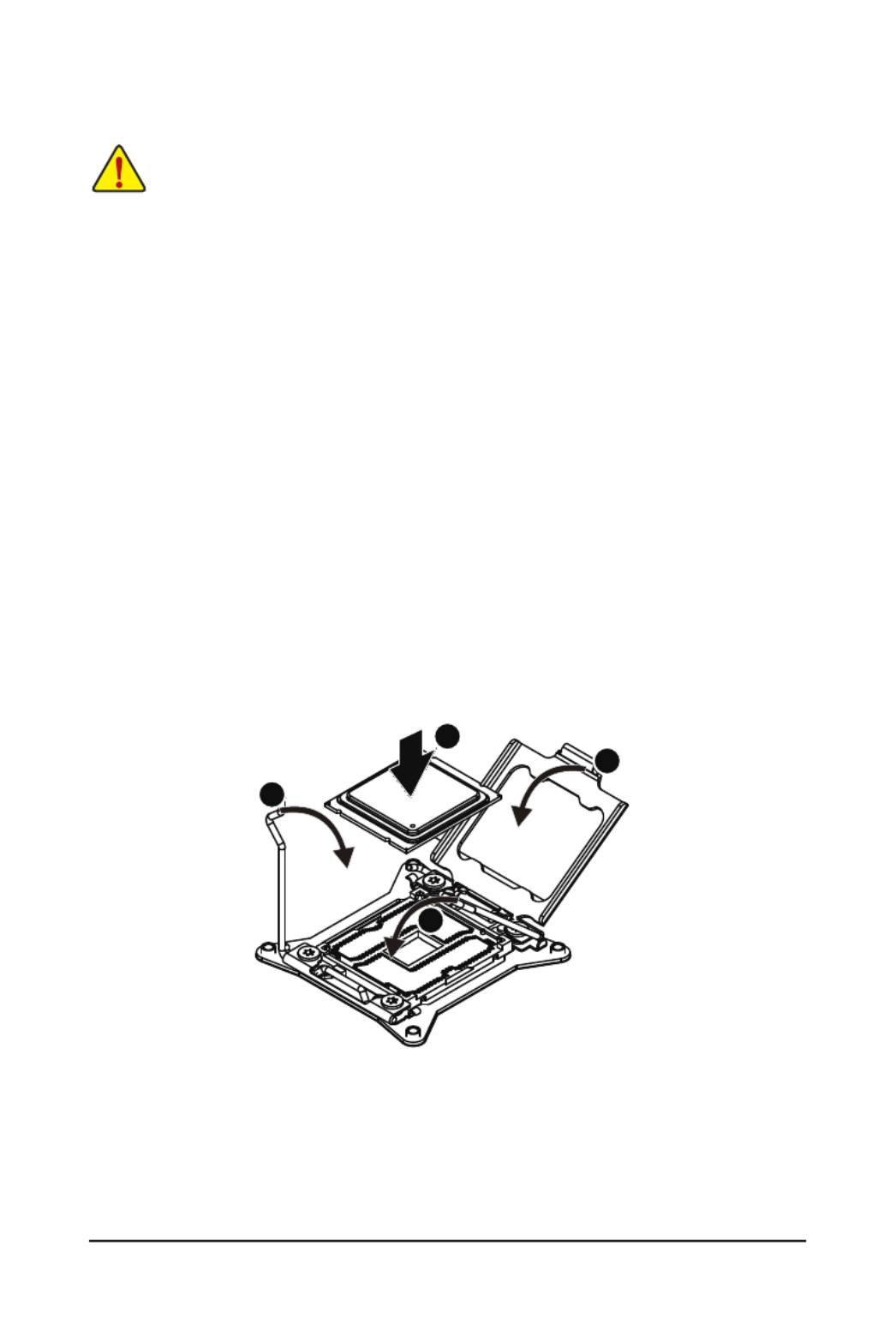
2-3 Installing the CPU
Read the following guidelines before you begin to install the CPU:
• Make sure that the motherboard supports the CPU.
• Always turn off the computer and unplug the power cord from the power outlet before installing
the CPU to prevent hardware damage.
• Unplug all cables from the power outlets.
• Disconnect all telecommunication cables from their ports.
• Place the system unit on a at and stable surface.
• Open the system according to the instructions.
WARNING!
Failure to properly turn off the server before you start installing components may cause serious
damage. Do not attempt the procedures described in the following sections unless you are a
qualied service technician.
Follow these instructions to install the CPU:
1. Raise the metal locking lever on the socket.
2. Remove the plastic covering on the CPU socket.Insert the CPU with the correct orientation. The
CPU only ts in one orientation.
3. Replace the metal cover.
4. Push the metal lever back into locked position.
1
2
3
4

- 19 - Hardware Installation
Follow these instructions to install the heat sinks:
1. Apply thermal compound evenly on the top of the CPU. Remove the protective cover from the
underside of the heat sink.
2. Place the heat sink(s) on top of the CPU.
3. Tighten the four positioning screws.
2-4 Installing the Heat Sink
1
2
3

Hardware Installation - 20 -
2-5 Installing the Memory
2-5-1 Four Channel Memory Conguration
This motherboard provides 24 DDR4 memory sockets and supports Four Channel Technology. After the
memory is installed, the BIOS will automatically detect the specifications and capacity of the memory.
Enabling Four Channel memory mode will be four times of the original memory bandwidth.
The four DDR4 memory sockets are divided into four channels each channel has two memory sockets as
following:
Channel 1: DIMM_P0_A0/DIMM_P0_A1/DIMM_P0_A2 (For pimary CPU);
DIMM_P1_E0/DIMM_P1_E1/DIMM_P1_E2 (For secondary CPU)
Channel 2: DIMM_P0_B0/DIMM_P0_B1/DIMM_P0_B2 (For pimary CPU);
DIMM_P1_F0/DIMM_P1_F1/DIMM_P1_F (For secondary CPU)
Channel 3: DIMM_P0_C0/DIMM_P0_C1/DIMM_P0_C2 (For pimary CPU);
DIMM_P1_G0/DIMM_P1_G1/DIMM_P1_G2 (For secondary CPU)
Channel 4: DIMM_P0_D0/DIMM_P0_D1/DIMM_P0_D2 (For pimary CPU);
DIMM_P1_H0/DIMM_P1_H1/DIMM_P1_H2 (For secondary CPU)
Read the following guidelines before you begin to install the memory:
• Make sure that the motherboard supports the memory. It is recommended that memory of the
same capacity, brand, speed, and chips be used.
• Always turn off the computer and unplug the power cord from the power outlet before installing
the memory to prevent hardware damage.
• Memory modules have a foolproof design. A memory module can be installed in only one
direction. If you are unable to insert the memory, switch the direction.
DIMM_P1_F2
DIMM_P1_F1
DIMM_P1_F0
DIMM_P1_E1
DIMM_P1_E0
DIMM_P1_E2
DIMM_P1_G0
DIMM_P1_G1
DIMM_P1_G2
DIMM_P1_H0
DIMM_P1_H1
DIMM_P1_H1
DIMM_P1_H2
DIMM_P0_B2
DIMM_P0_B1
DIMM_P0_B0
DIMM_P0_A2
DIMM_P0_A1
DIMM_P0_A0
DIMM_P0_C0
DIMM_P0_C1
DIMM_P0_C2
DIMM_P0_D0
DIMM_P0_D1
DIMM_P0_D2

- 21 - Hardware Installation
2-5-2 Installing a Memory
2-5-3 DIMM Population Table
Before installing a memory module, make sure to turn off the computer and unplug the power
cord from the power outlet to prevent damage to the memory module.
Be sure to install DDR4 DIMMs on this motherboard.
Follow these instructions to install the Memory:
1. Insert the DIMM memory module vertically into the DIMM slot, and push it down.
2. Close the plastic clip at both edges of the DIMM slots to lock the DIMM module.
3. Reverse the installation steps when you want to remove the DIMM module.
1
2
2
Type
Ranks Per
DIMM and
Data Width
Speed (MT/s);
Slot Per Channel (SPC) and DIMM Per Channel (DPC)
RDIMM
RDIMM
RDIMM
RDIMM
LRDIMM
LRDIMM
3DS
SRx4 2133
2133
2133
2133
2133
2133
2133
2133
2133
2133
1866
1866
1866
1866
2133
1 Slot Per Channel
1DPC
2 Slot Per Channel
1DPC 2DPC
SRx8
DRx8
DRx4
QRx4
2400 2400 24008Rx4
When only one DIMM is used, it must be populated in memory slot0 rst.
Memory populated sequence must be followed with slot0/slot1/slot2.
System will not boot normally with incorrect populated sequence.
NOTE!
DDR4 2400MHz is only available on Intel Xeon® E5-2600 V4 processor.

Hardware Installation - 22 -
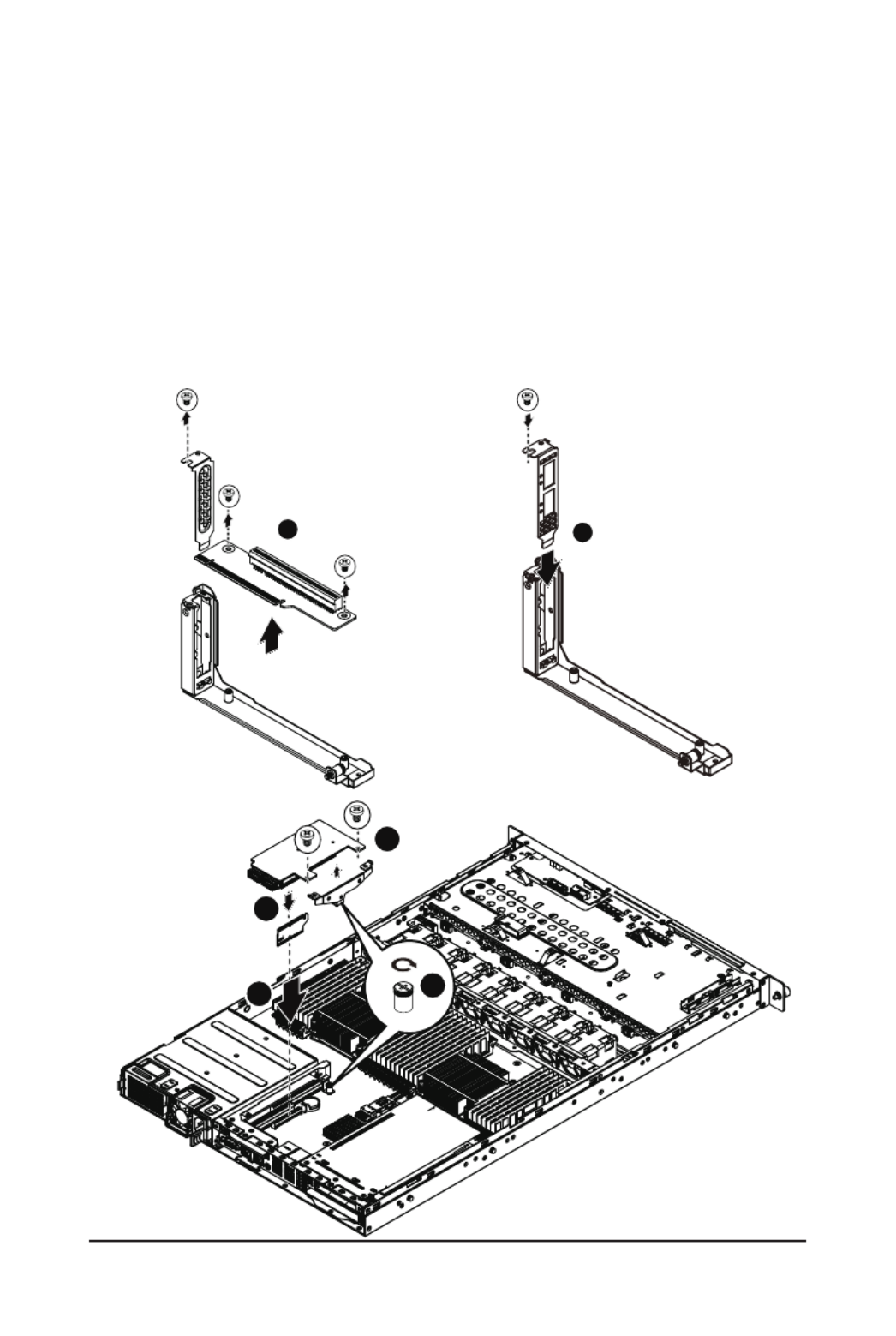
2-6 Installing the PCI Expansion Card
• Voltages can be present within the server whenever an AC power source is connected. This
voltage is present even when the main power switch is in the off position. Ensure that the
system is powered-down and all power sources have been disconnected from the server prior to
installing a PCI card.
Failure to observe these warnings could result in personal injury or damage to equipment.
• The PCI riser assembly does not include a riser card or any cabling as standard. To install a PCI
card, a riser card must be installed.
Follow these instructions to PCI Expansion card:
1. Remove the securing screw on the riser bracket.
2. Remove the securing special screw on the riser bracket.
3. Lift up the riser bracket out of system.
4. Loosen and remove the bracket securing screw.
5. Orient the PCI-E card with the riser guide slot and push in the direction of the arrow until the PCI-E
card sits in the PCI card connector.
6. Secure the PCI-E card with the screw.
7. Reverse the previous steps to install the riser bracket.
1
2
3
1
3
2
4
5
6
4
5
6
- 23 - Hardware Installation
2-6-1 Installing Add-on Card (Optional)
Follow these instructions to install Add-on card:
1. Remove theriser bracket from the system following the steps outlined in 2-6 Installing the PCI
Expansion Card.
2. Remove the PCI bracket and mini PCI card.
3. Insert the dedicated rear bracket and secure with screw.
4. Engage the support bracket with mezzaine card and secure with screws.
5. Attach the interposer card to the selected slot (PCIE_4).
6. Insert the add-on card into the interposer card. Make sure that the card is properly seated.
7. Tighten the thumbscrew.
12
3
5
46
Hardware Installation - 24 -
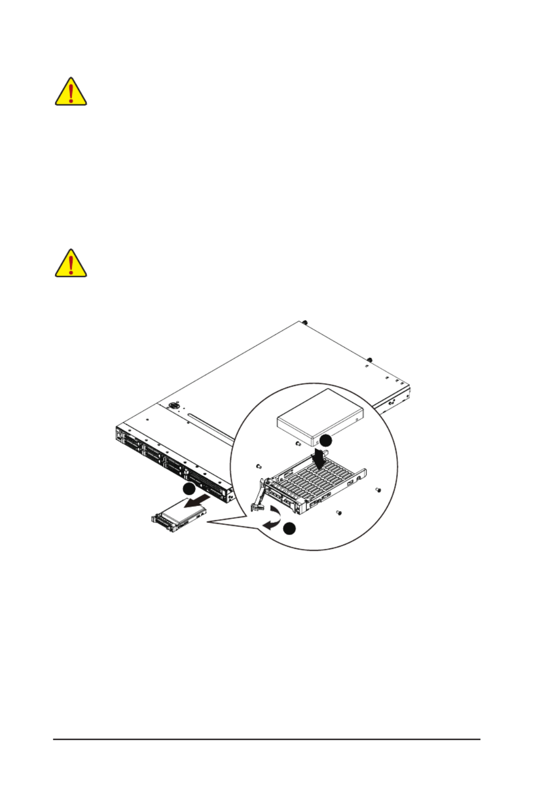
2-7 Installing the Hard Disk Drive
Read the following guidelines before you begin to install the Hard disk drive:
• Take note of the drive tray orientation before sliding it out.
• The tray will not t back into the bay if inserted incorrectly.
• Make sure that the HDD is connected to the HDD connector on the backplane.
CAUTION!
We strongly recommand using enterprise level hard disk drive in Gigabyte server system. For more
information of recommanded HDDs, please visit Gigabyte website: https://www.gigabyte.com and
serach for the specic product QVL from Support & Dowloads.
Follow these instructions to install the Hard disk drive:
1. Press the release button.
2. Pull the locking lever to remove the HDD tray. Remove the HDD dummy cover.
3. Slide hard disk into blank.
4. Secure the hard drive to the tray with four (4) screws as shown. Do not over tighten thescrews.
5. Slide the blank into the bay until it locks into place.
4
4
2
1
3

- 27 - Hardware Installation
2-10 Installing Rail Into A Rack
Follow these instructions to install the rail into a rack:
1. Release and detatch the inner rail from the slide.
2. Attach the unit to the inner rail.
3. Fix the outer rail/bracket assembly to the frame.
4. Insert the unit to complete the installation.
1
2
3
4

Hardware Installation - 28 -
Chapter 3 System Appearance
3-1 Front View
• Please Go to Chapter and Buttons for detail description of function LEDs.3-3 Front Panel LED
No. Decription
1. HDD bay#0
2. HDD bay#1
3. HDD bay#2
4. HDD bay#3
5. HDD bay#4
6. HDD bay#5
7. HDD bay#6
8. HDD bay#7
9. HDD bay#8
10. HDD bay#9
11. Front Panel LEDs and buttons
12 Front USB 3.0 ports
3-2 Rear View
No. Decription
1. Power supply fan
2. Power supply module cord socket
3. VGA port
4. RJ-45 LAN ports
5. ID switch button
6. RJ-45 COM port
7. USB 2.0 ports
8. 10/100/1000 Server management LAN port
9. USB 3.0 ports
10. Low-prole riser card bay
1 2 3 4 5 6 7 8 9 10
12
11
1
2
3
4
5
6
7
8
9
10

- 29 - Hardware Installation
3
4
2
1
5
6
No. Name Color Status Critical
Event
Description
1. Reset Button Press the button to reset the system.
2. ID Button Press the button to activate
system identication.
3. Power LED
Green Solid On System is powered onN/A
Green Blink N/A System is in ACPI S1 state (sleep mode)
N/A N/AOff
• System is not powered on or in ACPI S5
state (power off)
• System is in ACPI S4 state
(hibernate mode)
4. HDD Status
LED
Green On N/A HDD locate
Blink N/A HDD access
Amber On N/A HDD fault
Green/
Amber Blink N/A HDD rebuilding
N/A N/AOff • No HDD access
• No HDD fault
5. LAN1 Active/
Link LED
Green Solid On N/A Link between system and network
or no access
Green Blink N/A Data transmission or receiving is occurring
N/A N/AOff No data transmission or
receiving is occurring
6. LAN2 Active/
Link LED
Green Solid On N/A Link between system and network
or no access
Green Blink N/A Data transmission or receiving is occurring
N/A N/AOff No data transmission or
receiving is occurring
3-3 Front Panel LED and Buttons

Hardware Installation - 30 -
3-4 Rear System LAN LEDs
No. Name Color Status Description
1. 1GbE
Speed LED
Yellow On 1 Gbps data rate
Green On 100 Mbps data rate
N/A Off 10 Mbps data rate
2.
1GbE
Link/
Activity LED
Green
On Link between system and
network or no access
Blink Data transmission or receiving is occurring
N/A Off No data transmission or receiving is occurring
21
11 22

- 31 - Hardware Installation
3-5 Hard Disk Drive LEDs
1
2
No Description Multi Color LEDs
LED Active
Green
LED Active
Amber
1 HDD Access Blink Off
HDD Locate On Off
HDD Failure Off On
HDD connected and rebuilding data Blink Blink
(Alternative)
2 Reserve

Hardware Installation - 32 -
3-6 Cable Routing
No. Suggest Cable No. Suggest Cable
1. 2. Front panel USB 3.0 cableFront switch cable/Front LED cable
3. Mini SAS cable 4. HDD back plane board power cable
5. System fan power cable 6. System fan power cable
3
3
5
5
1
2
3
5
5 5 5
3
4
4
5
5
2
1
3

- 33 - Hardware Installation
Chapter 4 Motherboard Components
4-1 MD90-FS0 Motherboard Components
1 2 3 4 5 6
7
8
9
11 10
15 16
17
18
19
20
21
22
23
24
25
26
27
28
29
34
35
36
37
38
39
40
41
42
43
44
45
51
52
53
54
55
56
30313347484950
57
58
59
60 61
62 63
6465
66
67
69
68
70
71
72 73
74
46 32
12
13
14
Item Code Description
1 USB3_MLAN BMC Management LAN port (top) / USB 3.0 ports
(bottom)
2 COM1_USB2 RJ45 COM port (top) / USB 2.0 ports (bottom)/
3 ID switch buttonSW_ID
4 LAN1 port LAN1
5 LAN2 port LAN2
6 VGA port VGA
7 PCI Express p33-x16 slot RISER_SLOT3
8 PCI Express x16RISER_SLOT2
9 PCI Express p33-x16 slot (Proprietary slot)PCIE_4
10 BAT Battery socket
11 S3_MASK S3 Power On Select jumper
12 CASE_OPEN Case open intrusion alert header

Hardware Installation - 34 -
13 SW_RAID Intel/LSI Software RAID Key jumper
14 CLR_CMOS Clear CMOS jumper
15 PSU1 Hot-plug PSU module connector#1
16 PSU2 Hot-plug PSU module connector#1
17 ATX1 14 pin main power connector
18 12V_GPU3_2 4 pin 12V power connector
19 12V_GPU3_1 8 pin power connector
20 12V_GPU2_2 4 pin 12V power connector
21 12V_GPU2_1 8 pin power connector
22 12V_GPU1_2 4 pin 12V power connector
23 12V_GPU1_1 8 pin power connector
24 DIMM_P1_E0 Channel 1 slot 0 (for secondary CPU)
25 DIMM_P1_E1 Channel 1 slot 1 (for secondary CPU)
26 DIMM_P1_E2 Channel 1 slot 2 (for secondary CPU)
27 DIMM_P1_F0 Channel 2 slot 0 (for secondary CPU)
28 DIMM_P1_F1 Channel 2 slot 1 (for secondary CPU)
29 DIMM_P1_F2 Channel 2 slot 2 (for secondary CPU)
30 SYS_FAN5 System fan connector#5
31 SYS_FAN4 System fan connector#4
32 CPU1 Intel LGA2011 Socket R3 (Secondary CPU)
33 CPU1_FAN CPU1 fan connector (for Secondary CPU)
34 DIMM_P1_H2 Channel 3 slot 2 (for secondary CPU)
35 DIMM_P1_H1 Channel 3 slot 1 (for secondary CPU)
36 DIMM_P1_H0 Channel 3 slot 0 (for secondary CPU)
37 DIMM_P1_G2 Channel 4 slot 2 (for secondary CPU)
38 DIMM_P1_G1 Channel 4 slot 1 (for secondary CPU)
39 DIMM_P1_G0 Channel 4 slot 0 (for secondary CPU)
40 DIMM_P0_A0 Channel 4 slot 0 (for primary CPU)
41 DIMM_P0_A1 Channel 1 slot 1 (for primary CPU)
42 DIMM_P0_A2 Channel 1 slot 2 (for primary CPU)
43 DIMM_P0_B0 Channel 2 slot 0 (for primary CPU)
44 DIMM_P0_B1 Channel 2 slot 1 (for primary CPU)
45 DIMM_P0_B2 Channel 2 slot 2 (for primary CPU)
46 CPU0 Intel LGA2011 Socket R3 (Primary CPU)
47 CPU0_FAN CPU0 fan connector (for Primary CPU)
48 SYS_FAN3 System fan connector#3
49 SYS_FAN2 System fan connector#2
50 SYS_FAN1 System fan connector#1
51 DIMM_P0_D2 Channel 4 slot 2 (for primary CPU)
52 DIMM_P0_D1 Channel 4 slot 1 (for primary CPU)
53 DIMM_P0_D0 Channel 4 slot 0 (for primary CPU)
54 DIMM_P0_C2 Channel 3 slot 2 (for primary CPU)
55 DIMM_P0_C1 Channel 3 slot 1 (for primary CPU)
56 DIMM_P0_C0 Channel 3 slot 0 (for primary CPU)

- 35 - Hardware Installation
57 FP_1 Front panel header
58 BP_1 HDD back plane board header
59 IPMB IPMB connector
60 F_USB3 USB 3.0 header
61 BUZZER1 Buzzer
62 PCH_ME ME recovery jumper
63 ME_UPDATE ME update jumper
64 MINI_CN1 Mini-SAS cable connector#1 supports SATA3 6Gb/s
65 MINI_CN2 Mini-SAS cable connector#2 supports SATA3 6Gb/s
66 SATA5 SATA3 6Gb/s connector
67 SATA4 SATA3 6Gb/s connector
68 RISER_1_2 PCI Express x16 slot (Gigabyte extension slot)
69 BIOS_PWD Clearing Supervisor Password jumper
70 BIOS_RCVR BIOS recovery jumper
71 LED_BMC BMC rmware readiness LED
72 RISER_1_1 PCI Express x4 slot (Gigabyte extension slot)
73 BMC_FRB Force to Stop FRB Timer jumper
74 TPM TPM module connector

- 37 - BIOS Setup
BIOS (Basic Input and Output System) records hardware parameters of the system in the EFI on the
motherboard. Its major functions include conducting the Power-On Self-Test (POST) during system startup,
saving system parameters and loading operating system, etc. BIOS includes a BIOS Setup program that
allows the user to modify basic system conguration settings or to activate certain system features. When the
power is turned off, the battery on the motherboard supplies the necessary power to the CMOS to keep the
conguration values in the CMOS.
To access the BIOS Setup program, press the <F2> key during the POST when the power is turned on.
Chapter 5 BIOS Setup
• BIOS ashing is potentially risky, if you do not encounter problems of using the current BIOS
version, it is recommended that you don't ash the BIOS. To ash the BIOS, do it with caution.
Inadequate BIOS ashing may result in system malfunction.
• It is recommended that you not alter the default settings (unless you need to) to prevent system
instability or other unexpected results. Inadequately altering the settings may result in system's
failure to boot. If this occurs, try to clear the CMOS values and reset the board to default values.
(Refer to the Exit section in this chapter or introductions of the battery/clearing CMOS jumper in
Chapter 1 for how to clear the CMOS values.)
BIOS Setup Program Function Keys
<f><g > Move the selection bar to select the screen
<h><i > Move the selection bar to select an item
<+> Increase the numeric value or make changes
<-> Decrease the numeric value or make changes
<Enter> Execute command or enter the submenu
<Esc> Main Menu: Exit the BIOS Setup program
Submenus: Exit current submenu
<F1> Show descriptions of general help
<F3> Restore the previous BIOS settings for the current submenus
<F9> Load the Optimized BIOS default settings for the current submenus
<F10> Save all the changes and exit the BIOS Setup program

- 39 - BIOS Setup
5-1 The Main Menu
Once you enter the BIOS Setup program, the Main Menu (as shown below) appears on the screen. Use
arrow keys to move among the items and press <Enter> to accept or enter other sub-menu.
Main Menu Help
The on-screen description of a highlighted setup option is displayed on the bottom line of the Main Menu.
Submenu Help
While in a submenu, press <F1> to display a help screen (General Help) of function keys available for the
menu. Press <Esc> to exit the help screen. Help for each item is in the Item Help block on the right side of
the submenu.
• When the system is not stable as usual, select the item to set your system to Restore Defaults
its defaults.
• The BIOS Setup menus described in this chapter are for reference only and may differ by BIOS
version.

BIOS Setup - 40 -
BIOS Information
Porject Name
Display the project name information.
Porject Version
Display version number of the BIOS setup utility.
BIOS Build Date and Time
Displays the date and time when the BIOS setup utility was created.
BMC Information
BMC Firmware Version
Display BMC rmware version information.
SDR Version
Display the SDR version information.
FRU Version
Display the FRU version information.
Processor Information
CPU Brand String/Max CPU Speed/CPU Signature/Processors Core/Microcode Patch
Displays the technical specications for the installed processor.
Memory Information
Total Memory
Display the total memory size of the installed memory.
Memory Frequency
Display the frequency information of the installed memory.

- 41 - BIOS Setup
Onboard LAN Information
LAN1/LAN2/LAN3/LAN4 MAC Address
Display LAN1/LAN2/LAN/LAN4 MAC address information.
System Date
Set the date following the weekday-month-day- year format.
System Time
Set the system time following the hour-minute- second format.
BIOS Setup - 42 -
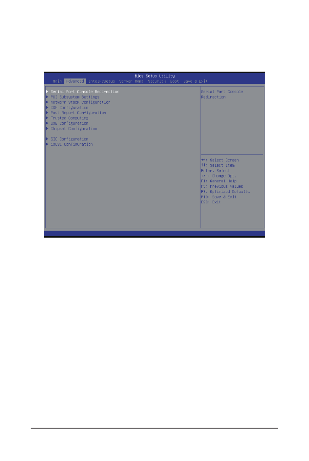
5-2 Advanced Menu
The Advanced menu display submenu options for conguring the function of various hardware components.
Select a submenu item, then press Enter to access the related submenu screen.
Termékspecifikációk
| Márka: | Gigabyte |
| Kategória: | szerver |
| Modell: | R180-F2A |
Szüksége van segítségre?
Ha segítségre van szüksége Gigabyte R180-F2A, tegyen fel kérdést alább, és más felhasználók válaszolnak Önnek
Útmutatók szerver Gigabyte

16 December 2024
11 Október 2024
6 Október 2024
29 Augusztus 2024
29 Augusztus 2024
29 Augusztus 2024
29 Augusztus 2024
29 Augusztus 2024
29 Augusztus 2024
29 Augusztus 2024
Útmutatók szerver
- szerver Sony
- szerver Fujitsu
- szerver Acer
- szerver StarTech.com
- szerver Lenovo
- szerver Toshiba
- szerver HP
- szerver Medion
- szerver Vimar
- szerver Technics
- szerver Rocstor
- szerver Digitus
- szerver TRENDnet
- szerver Dell
- szerver Tripp Lite
- szerver Conceptronic
- szerver Blackmagic Design
- szerver Hikvision
- szerver Netgear
- szerver Asus
- szerver ELAC
- szerver Synology
- szerver Supermicro
- szerver ZyXEL
- szerver Smart-AVI
- szerver Planet
- szerver Ernitec
- szerver Black Box
- szerver MSI
- szerver Cisco
- szerver ATen
- szerver APC
- szerver SEH
- szerver Western Digital
- szerver HGST
- szerver D-Link
- szerver Monacor
- szerver Moxa
- szerver Abus
- szerver Veritas
- szerver Atlona
- szerver Lindy
- szerver Areca
- szerver QNAP
- szerver NEC
- szerver Siig
- szerver Eaton
- szerver Gefen
- szerver Kathrein
- szerver IStarUSA
- szerver Lantronix
- szerver Provision-ISR
- szerver Axis
- szerver NETSCOUT
- szerver Sitecom
- szerver ACTi
- szerver Megasat
- szerver KanexPro
- szerver Kramer
- szerver Allnet
- szerver SilverStone
- szerver Maxdata
- szerver AVerMedia
- szerver Matrox
- szerver Flir
- szerver Buffalo
- szerver GeoVision
- szerver LevelOne
- szerver LaCie
- szerver Valcom
- szerver Asustor
- szerver Intel
- szerver Fantec
- szerver Freecom
- szerver Seagate
- szerver Iomega
- szerver Digi
- szerver Revox
- szerver Luxman
- szerver Ibm
- szerver Sonnet
- szerver TAIDEN
- szerver Advantech
- szerver Extron
- szerver Avocent
- szerver Intellinet
- szerver Teradek
- szerver Silex
- szerver Hanwha
- szerver In Win
- szerver Sun
- szerver MvixUSA
- szerver Dual Bay
- szerver Raidsonic
- szerver EMC
- szerver Infortrend
- szerver Opengear
- szerver G-Technology
- szerver EXSYS
- szerver Chenbro Micom
- szerver Middle Atlantic
- szerver Mr. Signal
- szerver Atlantis Land
- szerver C2G
- szerver Promise Technology
- szerver Mobotix
- szerver Origin Storage
Legújabb útmutatók szerver

9 Április 2025
3 Április 2025

2 Április 2025
29 Március 2025
29 Március 2025
29 Március 2025
24 Március 2025
24 Március 2025

15 Január 2025
15 Január 2025