Használati útmutató Gigabyte MS03-6L0
Olvassa el alább 📖 a magyar nyelvű használati útmutatót Gigabyte MS03-6L0 (99 oldal) a szerver kategóriában. Ezt az útmutatót 4 ember találta hasznosnak és 2 felhasználó értékelte átlagosan 4.5 csillagra
Oldal 1/99

MS03-6L0
4th Gen. Intel® Xeon® Scalable UP Motherboard
User Manual
Rev. 1.0

Copyright
© 2023 Giga Computing Technology CO., LTD. All rights reserved.
The trademarks mentioned in this manual are legally registered to their respective owners.
Disclaimer
Information in this manual is protected by copyright laws and is the property of Giga Computing.
Changes to the specications and features in this manual may be made by Giga Computing
without prior notice. No part of this manual may be reproduced, copied, translated, transmitted, or
published in any form or by any means without Giga Computing's prior written permission.
Documentation Classications
In order to assist in the use of this product, Giga Computing provides the following types of documen-
tation:
User Manual: detailed information & steps about the installation, conguration and use of this
product (e.g. motherboard, server barebones), covering hardware and BIOS.
User Guide: detailed information about the installation & use of an add-on hardware or
software component (e.g. BMC rmware, rail-kit) compatible with this product.
Quick Installation Guide: a short guide with visual diagrams that you can reference easily for
installation purposes of this product (e.g. motherboard, server barebones).
Please see the support section of the online product page to check the current availability of these
documents.
For More Information
For related product specications, the latest rmware and software, and other information please visit our website at
http://www.gigabyte.com/Enterprise
For GIGABYTE distributors and resellers, additional sales & marketing materials are available from our reseller
portal: http://reseller.b2b.gigabyte.com
For further technical assistance, please contact your GIGABYTE representative or visit
https://esupport.gigabyte.com/ to create a new support ticket
For any general sales or marketing enquiries, you may also message GIGABYTE server directly by email:
server.grp@gigabyte.com

- 3 -
Table of Contents
MS03-6L0 Motherboard Layout 5 .......................................................................................
Block Diagram 7 .................................................................................................................
Chapter 1 Hardware Installation 8 .....................................................................................
1-1 Installation Precautions 8 ....................................................................................
1-2 ProductSpecications ...................................................................................... 9
1-3 Installing and Removing the CPU 12 ..................................................................
1-4 Installing and Removing Memory 14 ...................................................................
1-4-1 Eight-ChannelMemoryConguration ...................................................................14
1-4-2 Installing and Removing a Memory Module 15 ..........................................................
1-4-3 DIMM Population Table .........................................................................................15
1-4-4 Processor and Memory Module Matrix Table 15 .........................................................
1-5 Installing the M.2 SSD Module 16 .......................................................................
1-6 Back Panel Connectors 17 ..................................................................................
1-7 Internal Connectors 18 ........................................................................................
1-8 Jumper Settings 29 .............................................................................................
Chapter 2 BIOS Setup 30 ..................................................................................................
2-1 The Main Menu 32 ..............................................................................................
2-2 Advanced Menu 35 .............................................................................................
2-2-1 Trusted Computing 36 .................................................................................................
2-2-2 Serial Port Console Redirection 37 .............................................................................
2-2-3 SIOConguration ...................................................................................................40
2-2-4 PCI Subsystem Settings 41 .........................................................................................
2-2-5 USBConguration ..................................................................................................43
2-2-6 NetworkStackConguration ..................................................................................44
2-2-7 PostReportConguration ......................................................................................45
2-2-8 NVMeConguration ...............................................................................................46
2-2-9 ChipsetConguration .............................................................................................47
2-2-10 TlsAuthConguration ............................................................................................48
2-2-11 iSCSIConguration ................................................................................................49
2-2-12 Intel(R) i210 Gigabit Network Connection 50 ..............................................................
2-2-13 VLANConguration ................................................................................................52
2-2-14 Broadcom BCM57416 NetXtreme-E 10GBASE-T RDMA Ethernet Controller 53 .......
2-2-15 VLANConguration ................................................................................................59
2-2-16 Driver Health 60 ...........................................................................................................
2-3 Chipset Menu 61 .................................................................................................
2-3-1 ProcessorConguration .........................................................................................62

- 4 -
2-3-2 CommonRefCodeConguration ...........................................................................65
2-3-3 UPIConguration ...................................................................................................66
2-3-4 MemoryConguration ............................................................................................68
2-3-5 IIOConguration ....................................................................................................71
2-3-6 AdvancedPowerManagementConguration ........................................................73
2-3-7 PCHConguration ..................................................................................................75
2-3-8 MiscellaneousConguration ..................................................................................77
2-3-9 ServerMEConguration ........................................................................................78
2-3-10 Runtime Error Logging Settings 79 .............................................................................
2-3-11 Power Policy 81 ...........................................................................................................
2-4 Server Management Menu 83 .............................................................................
2-4-1 System Event Log 85 ..................................................................................................
2-4-2 View FRU Information 86 ............................................................................................
2-4-3 BMCVLANConguration .......................................................................................87
2-4-4 BMCNetworkConguration ...................................................................................88
2-4-5 IPv6BMCNetworkConguration ...........................................................................89
2-5 Security Menu 90 ................................................................................................
2-5-1 Secure Boot 91 ...........................................................................................................
2-6 Boot Menu 94 ......................................................................................................
2-7 Save & Exit Menu 96 ...........................................................................................
2-8 BIOS Recovery 98 ..............................................................................................
2-9 BIOS POST Beep code (AMI standard) 99 .........................................................
2-9-1 PEI Beep Codes 99 .....................................................................................................
2-9-2 DXE Beep Codes 99 ...................................................................................................
- 5 -
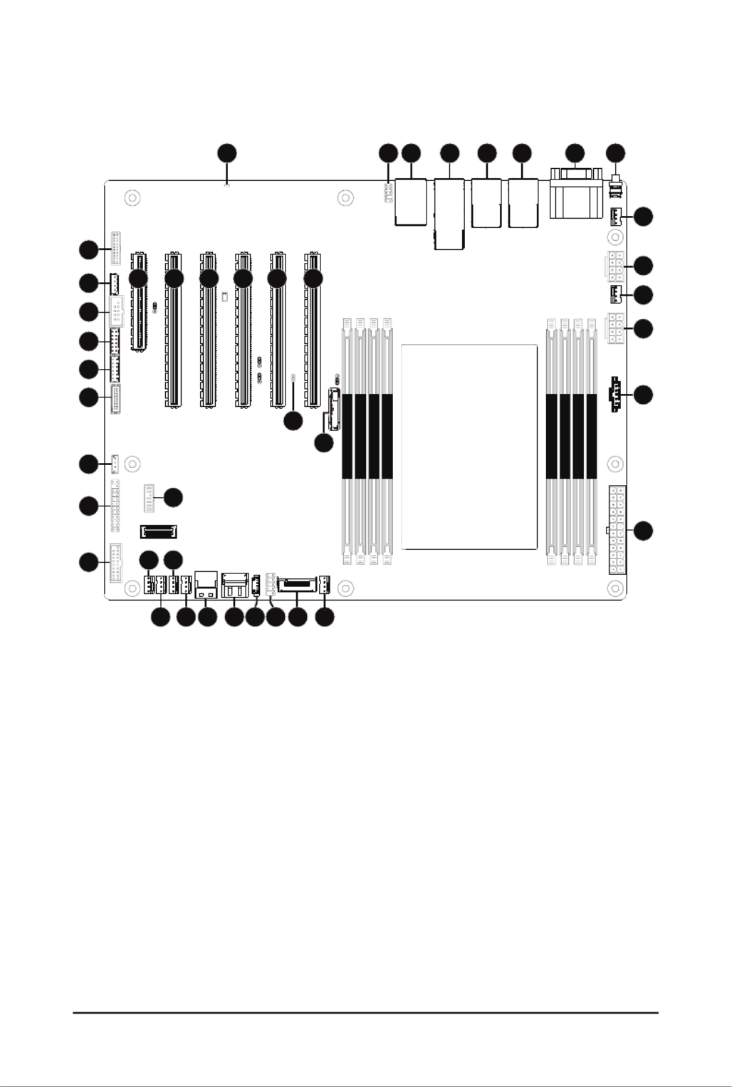
MS03-6L0 Motherboard Layout
DIMM_P0_D0
DIMM_P0_C0
DIMM_P0_B0
DIMM_P0_A0
DIMM_P0_H0
DIMM_P0_E0
DIMM_P0_F0
DIMM_P0_G0
CPU0
5 6 71 3 42
9
11
12
13
151920
22
23
24
14
1617
25
26 27
29
33
42
8
10
1821
373635 38 39 41
40
32
34
31
30
28

- 6 -
Item Code Description
1 LED_BMC BMC Firmware Readiness LED
2 F_AUDIO1 Front Audio Header
3 USB3_MLAN Server Management LAN Port (Top)/USB 3.2 Gen1 Ports (Bottom)
4 10G_LAN1_2 10GbE LAN Port #1/#2
5 LAN_3_4 1GbE LAN Port #3/#4
6 LAN_5_6 1GbE LAN Port #5/#6
7 COM1_VGA Serial Port (Top)/VGA Port (Bottom)
8 SW_ID ID Button with LED
9 SYS_FAN6 System Fan Connector #6
10 P12V_AUX1 2x4 Pin 12V Power Connector
11 CPU0_FAN CPU Fan Connector
12 P12V_AUX2 2x4 Pin 12V Power Connector
13 PMBUS PMBus Connector
14 ATX1 2x12 Pin Main Power Connector
15 SYS_FAN5 System Fan Connector #5
16 M2_0 M.2 Slot (PCIe Gen3 x4, Support NGFF-2280)
17 F_USB2 Front USB 2.0 Header
18 SATA_SGPIO SATA SGPIO Connector
19 SATA_4_5 SATA 6Gb/s Connector #4/#5
20 SL_SATA1 Slimline Connector (SATA 6Gb/s Signal)
21 SYS_FAN4 System Fan Connector #4
22 SYS_FAN2 System Fan Connector #2
23 SYS_FAN1 System Fan Connector #1
24 SYS_FAN3 System Fan Connector #3
25 F_USB1 Front Panel USB 3.2 Gen1 Connector
26 FP_1 Front Panel Header
27 SPI_TPM TPM Connector
28 SW_RAID VROC Module Connector
29 BP_1 HDD Backplane Board Connector
30 GPIO_CNT_1 GPIO Connector #1
31 GPIO_CNT_2 GPIO Connector #2
32 COM2 Serial Port Cable Connector
33 IPMB IPMB Connector
34 CN_NCSI NCSI Connector
35 PCIE_1 PCIe x16 Slot #1 (Gen5 x8)
36 PCIE_2 PCIe x16 Slot #2 (Gen5 x16)
37 PCIE_3 PCIe x16 Slot #3 (Gen5 x16)
38 PCIE_4 PCIe x16 Slot #4 (Gen5 x16)
39 PCIE_5 PCIe x16 Slot #5 (Gen5 x16)
40 CASE_OPEN Case Open Intrusion Alert Header
41 PCIE_6 PCIe x16 Slot #6 (Gen5 x16)
42 Battery SocketBAT

- 7 -
Block Diagram

- 8 -
Hardware Installation
1-1 Installation Precautions
The motherboard contains numerous delicate electronic circuits and components which can
become damaged as a result of electrostatic discharge (ESD). Prior to installation, carefully read
the user's manual and follow these procedures:
• Prior to installation, do not remove or break motherboard S/N (Serial Number) sticker or
warranty sticker provided by your dealer. These stickers are required for warranty validation.
• Always remove the AC power by unplugging the power cord from the power outlet before
installing or removing the motherboard or other hardware components.
• When connecting hardware components to the internal connectors on the motherboard,
make sure they are connected tightly and securely.
• When handling the motherboard, avoid touching any metal leads or connectors.
• It is best to wear an electrostatic discharge (ESD) wrist strap when handling electronic
components such as a motherboard, CPU or memory. If you do not have an ESD wrist
strap,keepyourhandsdryandrsttouchametalobjecttoeliminatestaticelectricity.
•
Prior to installing the motherboard, please have it on top of an antistatic pad or within an
electrostatic shielding container.
• Before unplugging the power supply cable from the motherboard, make sure the power
supply has been turned off.
• Before turning on the power, make sure the power supply voltage has been set according to
the local voltage standard.
• Before using the product, please verify that all cables and power connectors of your
hardware components are connected.
• To prevent damage to the motherboard, do not allow screws to come in contact with the
motherboard circuit or its components.
• Make sure there are no leftover screws or metal components placed on the motherboard or
within the computer casing.
• Do not place the computer system on an uneven surface
.
• Do not place the computer system in a high-temperature environment.
• Turning on the computer power during the installation process can lead to damage to
system components as well as physical harm to the user.
• If you are uncertain about any installation steps or have a problem related to the use of the
product,pleaseconsultacertiedcomputertechnician.
• To avoid any potential short circuit of the DIMM slots, please remove any stand-offs from the
chassis that will be located underneath the DIMM slots, before installing the motherboard
into the chassis.
Chapter 1 Hardware Installation

- 9 -
Hardware Installation
1-2 Product Specications
Form Factor ATX
304.8W x 254D (mm)
CPU 4th Generation Intel® Xeon® Scalable Processors
Intel® Xeon® CPU Max Series
Intel® Xeon® Platinum Processor, ® Xeon® Gold Processor,
Intel® Xeon® Silver Processor
CPU TDP up to 350W
Socket
Socket 1 x LGA 4677
Socket E
Chipset Intel® C741 Chipset
Memory 8 x DIMM slots
DDR5 memory supported only
8-Channel memory architecture
RDIMM modules up to 128GB supported
3DS RDIMM modules up to 256GB supported
Memory speed: Up to 4800 MHz
LAN 2 x 10Gb/s LAN ports (Broadcom® BCM57416)
4 x 1Gb/s LAN ports (Intel® I210-AT)
BCM57416 with NCSI function supported
1 x 10/100/1000 management LAN
Onboard
Graphics
Integrated in Aspeed® AST2600
2D Video Graphic Adapter with PCIe bus interface
1920x1200@60Hz 32bpp, DDR4 SDRAM
Audio Realtek® ALC897 controller
Supports2/4/5.1/7.1channelcongurations
Storage Interface 1 x SlimSAS with 4 x SATA 6Gb/s ports
2 x SATA 6Gb/s ports
RAID Intel® SATA RAID 0/1/10/5
NOTE:
We reserve the right to make any changes to the product specications and product-related
information without prior notice.

- 10 -
Hardware Installation
Expansion Slots Slot_6: 1 x PCIe x16 (Gen5 x16 bus) slot, from CPU
Slot_5: 1 x PCIe x16 (Gen5 x16 bus) slot, from CPU
Slot_4: 1 x PCIe x16 (Gen5 x16 bus) slot, from CPU
Slot_3: 1 x PCIe x16 (Gen5 x16 bus) slot, from CPU
Slot_2: 1 x PCIe x16 (Gen5 x16 or p10-x8 bus) slot, from CPU, shared with Slot_1
Slot_1: 1 x PCIe p10-x8 (Gen5 p10-x8 bus) slot, from CPU
1 x M.2 slot:
- M-key
- PCIe Gen3 p10-x4 per slot, from PCH
- Supports 2280 cards
Internal I/O
Connectors
1 x 24-pin ATX main power connector
2 x 8-pin ATX 12V power connectors
1 x M.2 slot
1 x CPU fan headers
7 x System fan headers
2 x USB 3.2 Gen1 headers
2 x USB 2.0 headers
1 x TPM header
1 x VROC connector
1 x Front panel header
1 x HDD backplane board header
1 x PMBus connector
1 x IPMB connector
1xClearCMOSjumper
1xBIOSrecoveryjumper
1 x Buzzer
Rear I/O
Connectors
2 x USB 3.2 Gen1
1 x VGA
1 x COM
6 x RJ45
1 x MLAN
1 x ID button with LED
TPM 1 x TPM Header with SPI Interface
Optional TPM2.0 kit: CTM010

- 11 -
Hardware Installation
Board
Management
Aspeed® AST2600 Management Controller
GIGABYTE Management Console (AMI MegaRAC SP-X) Web Interface
Dashboard
HTML5 KVM
Sensor Monitor (Voltage, RPM, Temperature, CPU Status …etc.)
Sensor Reading History Data
FRU Information
SEL Log in Linear Storage / Circular Storage Policy
Hardware Inventory
FanProle
System Firewall
Power Consumption
Power Control
LDAP / AD / RADIUS Support
Backup&RestoreConguration
Remote BIOS/BMC/CPLD Update
Event Log Filter
User Management
Media Redirection Settings
PAM Order Settings
SSL Settings
SMTP Settings
Operating
Properties Operating temperature: 10°C to 40°C
Operating humidity: 8-80% (non-condensing)
Non-operating temperature: -40°C to 60°C
Non-operating humidity: 20%-95% (non-condensing)

- 12 -
Hardware Installation
1-3 Installing and Removing the CPU
Read the following guidelines before you begin to install the CPU:
• Make sure that the motherboard supports the CPU.
• Always turn off the computer and unplug the power cord from the power outlet before installing
the CPU to prevent hardware damage.
• Unplug all cables from the power outlets.
• Disconnect all telecommunication cables from their ports.
• Placethesystemunitonaatandstablesurface.
• Open the system according to the instructions.
WARNING!
Failure to properly turn off the server before you start installing components may cause serious
damage. Do not attempt the procedures described in the following sections unless you are a
qualiedservicetechnician.
Follow these instructions to Install the CPU:
1. Align and install the processor on the carrier.
NOTE: Apply thermal compound evenly on the top of the CPU. Remove the protective cover from
the underside of the heat sink.
2. Carefullyiptheheatsinkcover.Theninstallthecarrierassemblyonthebottomoftheheatsink
and make sure the gold arrow is located in the correct direction.
3. Remove the CPU cover.
NOTE: Save the CPU cover in the event that you need to remove the CPU from the socket.
4. Align the heat sink with the CPU socket by the guide pins and make sure the gold arrow is located
in the correct direction. Then place the heat sink onto the top of the CPU socket.
5. Position the rotating wires into the latch position. Tighten the screws in a sequential order
(1g2g3g4).
NOTE: When dissembling the heat sink, loosen the screws in reverse order (4g3g2g1) and
then move the rotating wires into the unlatch position.
Pin1 1
2

- 13 -
Hardware Installation
3
4
5
1
2
3
4
Note!
• The carrier code is marked on each carrier and matches a code laser marked on to the IHS(Integrated
Heat Spreader) to ensure the right parts are used together
• The illustrations of the heat-sink installation shown are for reference only.
Package Type
Carrier Code
Xeon® SP XCC Xeon® SP MCC Xeon® SP+HBM
E1A E1CE1B
Carrier Types used for Package Types

- 14 -
Hardware Installation
1-4 Installing and Removing Memory
Read the following guidelines before you begin to install the memory:
• Make sure that the motherboard supports the memory. It is recommended to use memory of the
same capacity, brand, speed, and chips.
• Always turn off the computer and unplug the power cord from the power outlet before installing
the memory to prevent hardware damage.
• Memory modules have a foolproof design. A memory module can be installed in only one
direction. If you are unable to insert the memory, switch the direction.
1-4-1 Eight-Channel Memory Conguration
This motherboard provides 8 DDR5 memory slots and supports Eight-Channel Technology. After the memory
isinstalled,theBIOSwillautomaticallydetectthespecicationsandcapacityofthememory.
DIMM_P0_D0
DIMM_P0_C0
DIMM_P0_B0
DIMM_P0_A0
DIMM_P0_H0
DIMM_P0_E0
DIMM_P0_F0
DIMM_P0_G0
CPU0

- 15 -
Hardware Installation
1-4-2 Installing and Removing a Memory Module
Before installing a memory module, make sure to turn off the computer and unplug the
power cord from the power outlet to prevent damage to the memory module.
Be sure to install DDR5 DIMMs on this motherboard.
1
2
2
Follow these instructions to install a DIMM module:
1. Insert the DIMM memory module vertically into the DIMM slot and push it down.
2. Close the plastic clip at both edges of the DIMM slots to lock the DIMM module.
3. Reverse the installation steps when you want to remove the DIMM module.
1-4-3 DIMM Population Table
Type Ranks Per DIMM
and Data Width
DIMM
Capacity
(GB)
Speed (MT/s); Voltage (V);
DIMM per Channel (DPC)
1DPC*
16Gb 1.1V
RDIMM
SRx8 (RC D) 16GB
4800
SRx4 (RC C) 32GB
SRx4 (RC F) 9x4 32GB
DRx8 (RC E) 32GB
DRx4 (RC A) 64GB
DRx4 (RC B) 9x4 64GB
RDIMM 3DS (4R/8R)x4
(RC A)
2H-128GB
4H-256GB
*1DPC applies to 1SPC or 2SPC implementations (SPC - Sockets Per Channel)
1-4-4 Processor and Memory Module Matrix Table
4 DIMM
Memory Q’ty
1 DIMM
2 DIMM
8 DIMM
CPU0
D0 C0 A0 E0 F0 G0 H0B0
V
V V
VVVV
VV V V VVVV
- 16 -
Hardware Installation
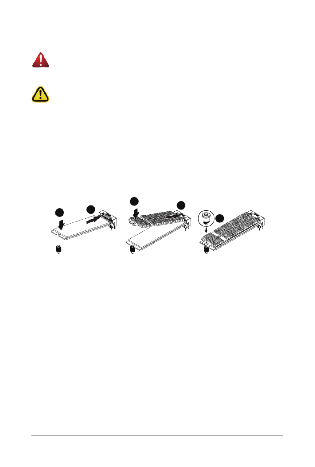
1-5 Installing the M.2 SSD Module
WARNING:
Installation of the thermal pad over the M.2 device is required when installing an M.2 device. Lack
of the thermal pad may result in the system overheating and throttle the system performance.
CAUTION
The position of the stand-off screw will depend on the size of the M.2 device. The stand-off screw
is pre-installed for 22110 cards as standard. Refer to the size of the M.2 device and change the
position of the stand-off screw accordingly.
Follow these instructions to install the M.2 device and heat sink:
1. Insert the M.2 device into the M.2 connector.
2. Press down on the M.2 device.
3. Install the thermal pad of the M.2 device to the M.2 device.
4. Press down on the thermal pad.
5. Secure the M.2 device and its thermal pad to the motherboard with a single screw.
6. Reverse steps 1-5 to remove the M.2 device.
1
4
2
3
5

- 17 -
Hardware Installation
1-6 Back Panel Connectors
1ID button with LED
Whenthesystemidenticationisactive,theIDLEDonthefront/backpanelglowsblue.
2Serial Port
Connect to serial-based mouse or data processing devices.
3VGA Port
Connect to a monitor device.
41GbE LAN Port #5/#6
The Gigabit Ethernet LAN port provides Internet connection at up to 1 Gbps data rate. See the section
below for a description of the states of the LAN port LEDs.
51GbE LAN Port #3/#4
The Gigabit Ethernet LAN port provides Internet connection at up to 1 Gbps data rate. See the section
below for a description of the states of the LAN port LEDs.
610GbE LAN Port #1/#2
The Gigabit Ethernet LAN port provides Internet connection at up to 10 Gbps data rate. See the section
below for a description of the states of the LAN port LEDs.
7Server Management LAN Port
The LAN port provides Internet connection with data transfer speeds of 10/100/1000Mbps. This port is
the dedicated LAN port for Server Management.
8USB 3.2 Gen1 Ports
The USB port supports the USB 3.2 specification. Use this port for USB devices such as a USB
keyboard/mouse,USBprinter,USBashdriveetc.
1
2
3
4 5
7
6
8
• Whenremovingthecableconnectedtoabackpanelconnector,rstremovethecablefromyour
device and then remove it from the motherboard.
• When removing the cable, pull it straight out from the connector. Do not rock it side to side to
prevent an electrical short inside the cable connector.
LAN and ID Button LEDs
Link/Activity LEDSpeed LED
LAN Port
ID button/LED:
10/100/1000 LAN LED:
State Description
Yellow On 1Gbps data rate
Green On 100Mbps data rate
Off 10Mbps data rate
State Description
Blue On Systemidenticationisactive
Off Systemidenticationisdisabled
10GbE LAN LED:
State Description
Yellow On 5Gbps, 2.5Gbps, 1Gbps data rate
Green On 10Gbps data rate
Off 100Mbps data rate

- 18 -
Hardware Installation
1-7 Internal Connectors
Read the following guidelines before connecting external devices:
• First make sure your devices are compliant with the connectors you wish to connect.
• Before installing the devices, be sure to turn off the devices and your computer. Unplug the power
cord from the power outlet to prevent damage to the devices.
• After installing the device and before turning on the computer, make sure the device cable has
been securely attached to the connector on the motherboard.
1) ATX1 12) FP_1
2) P12V_AUX1 13) BP_1
3) P12V_AUX2 14) COM2
4) SATA_4_5 15) SPI_TPM
5) SATA_SGP2 16) IPMB
6) SW_RAID 17) CN_NCSI
7) CPU0_FAN 18) F_AUDIO1
8) SYS_FAN1/2//3/4/5/6 19) GPIO_CNT_1/GPIO_CNT_2
9) PMBUS 20) LED_BMC
10) F_USB1 21) BAT
11) F_USB2 22) CASE_OPEN
DIMM_P0_D0
DIMM_P0_C0
DIMM_P0_B0
DIMM_P0_A0
DIMM_P0_H0
DIMM_P0_E0
DIMM_P0_F0
DIMM_P0_G0
CPU0
20
8
11
18
21
1
2
3
4 5
6
7
88
9
10
12
13
14
15
16
17
19
22
- 19 -
Hardware Installation
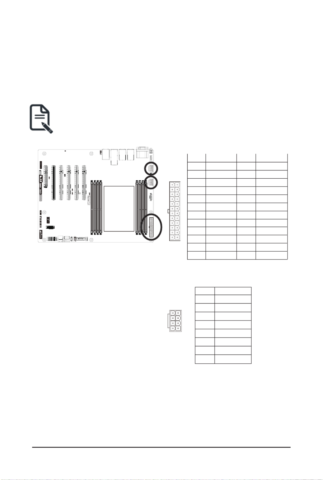
1/2/3) ATX1/P12V_AUX1/P12V_AUX2
(2x12 Main Power Connector and 2x4 12V Power Connector)
With the use of the power connector, the power supply can supply enough stable power to all the components
onthemotherboard.Beforeconnectingthepowerconnector,rstmakesurethepowersupplyisturnedoff
and all devices are properly installed. The power connector possesses a foolproof design. Connect the power
supply cable to the power connector in the correct orientation. The 12V power connector mainly supplies
power to the CPU. If the 12V power connector is not connected, the computer will not start.
To meet expansion requirements, it is recommended that a power supply that can withstand high
power consumption be used (500W or greater). If a power supply is used that does not provide the
required power, the result can lead to an unstable or unbootable system.
ATX1
P12V_AUX1/P12V_AUX2
8
5
4
1
PinNo. Denition
1 GND
2 GND
3 GND
4 GND
5 +12V
6 +12V
7 +12V
8 +12V
Pin No. Pin No.Denition Denition
1 3.3V 13 3.3V
2 3.3V 14 -12V
3 GND 15 GND
4 +5V 16 PS_ON
5 GND 17 GND
6 +5V 18 GND
7 GND 19 GND
8 Power Good 20 -5V
9 5VSB 21 +5V
10 +12V 22 +5V
11 +12V 23 +5V
12 3.3V 24 GND
113
1224

- 20 -
Hardware Installation
4) SATA_4_5 (SATA III 6Gb/s Connectors)
The SATA connectors conform to SATA III 6Gb/s standard and are compatible with SATA 3Gb/s standard.
Each SATA connector supports a single SATA device.
PinNo. Denition
1 GND
2 TXP
3 TXN
4 GND
5 RXN
6 RXP
7 GND
17
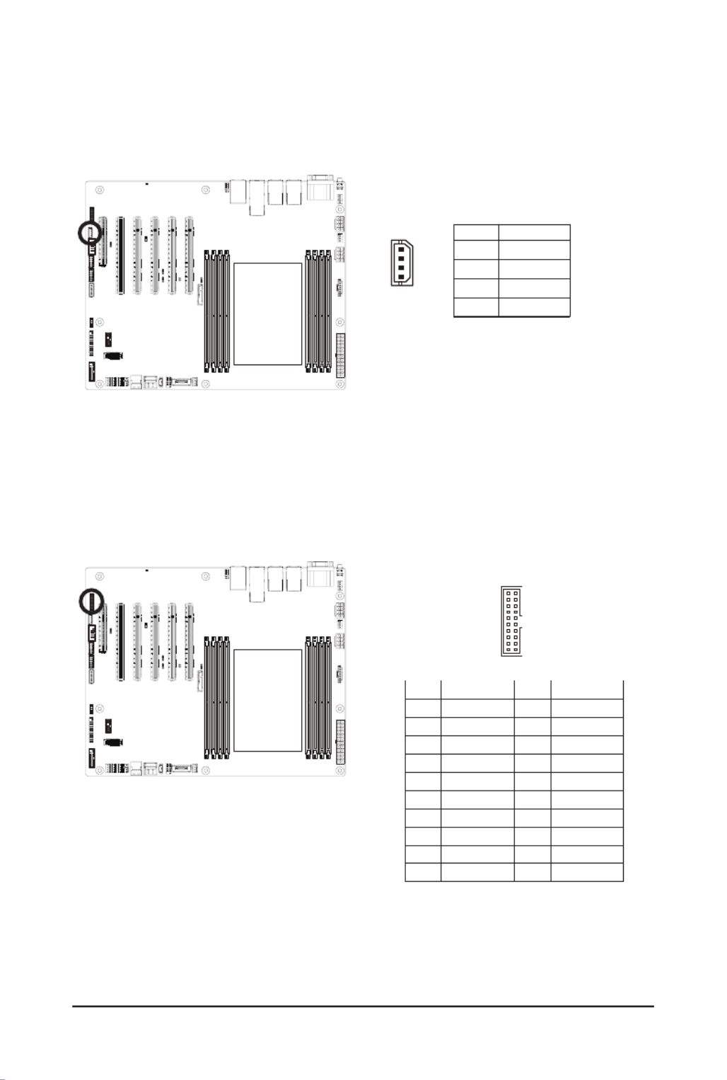
5) SATA_SGP2 (SATA SGPIO Connector)
Serial General Purpose Input/Output (SGPIO) is a communication method used between a host bus adapter
(HBA) and a main board.
Pin No. Denition
1 DATAOUT
2 GND
3 NC
4 Load
5 Clock
1
5

- 21 -
Hardware Installation
6) SW_RAID (VROC Module Connector)
1
4
Pin No. Denition
1 GND
2 P_3V3_AUX
3 GND
4 PCH_SATA_RAID_KEY
7/8) CPU0_FAN/SYS_FAN1/SYS_FAN2/SYS_FAN3/SYS_FAN4/SYS_FAN5/SYS_FAN6
(Fan Headers)
The motherboard has one 4-pin CPU fan header (CPU_FAN), and six 4-pin (SYS_FAN) system fan headers.
Most fan headers possess a foolproof insertion design. When connecting a fan cable, be sure to connect
it in the correct orientation (the black connector wire is the ground wire). The motherboard supports CPU
fan speed control, which requires the use of a CPU fan with fan speed control design. For optimum heat
dissipation, it is recommended that a system fan be installed inside the chassis.
1
1
PinNo. Denition
1 GND
2 +12V
3 Sense
4 Speed Control
• Be sure to connect fan cables to the fan headers to prevent your CPU and system from
overheating. Overheating may result in damage to the CPU or the system may hang.
• Thesefanheadersarenotconfigurationjumperblocks.Donotplaceajumpercaponthe
headers.

- 22 -
Hardware Installation
9) PMBus Connector
The Power Management Bus (PMBus) is a variant of the System Management Bus (SMBus) which is
targeted at digital management of power supplies.
5
1
PinNo. Denition
1 PMBus Clock
2 PMBus Data
3 PMBus Alert
4 GND
5 3.3V Sense
10/11) F_USB1/F_USB2 (Front Panel USB 3.2 Gen1 Connector/2.0 Header)
The connector/header conform to USB 2.0/3.2 specication.Each USB connector/header can providetwo
USB ports via an optional USB bracket. For purchasing the optional USB bracket, please contact the local
dealer.
1110
201
1
11 10
20
Pin No. Pin No.Denition Denition
1 Power IntA_P2_D+11
2 IntA_P1_SSRX- 12 IntA_P2_D-
3 IntA_P1_SSRX+ 13 GND
4 GND 14 IntA_P2_SSTX+
5 IntA_P1_SSTX- 15 IntA_P2_SSTX-
6 IntA_P1_SSTX+ 16 GND
7 GND 17 IntA_P2_SSRX+
8 IntA_P1_D- 18 IntA_P2_SSRX-
9 IntA_P1_D+ 19 Power
10 NC 20 No Pin
USB 2.0 Header
USB 3.2 Gen1 Connector
Pin No. Pin No.Denition Denition
1 Power (5V) 6 USB DY+
2 Power (5V) 7 GND
3 USB DX- 8 GND
4 USB DY- 9 No Pin
5 USB DX+ 10 No Connect
1 2
9 10

- 23 -
Hardware Installation
12) FP_1 (Front Panel Header)
Connect the power switch, reset switch, speaker, chassis intrusion switch/sensor and system status indicator
on the chassis to this header according to the pin assignments below. Note the positive and negative pins
before connecting the cables.
The front panel design may differ by chassis. A front panel module mainly consists of power switch,
reset switch, power LED, hard drive activity LED, speaker etc. When connecting your chassis front
panel module to this header, make sure the wire assignments and the pin assignments are matched
correctly.
Pin No. Denition DenitionPin No.
1 Power LED+ 2 5V Standby
3 No Pin 4 ID LED+
5 Power LED- 6 ID LED-
7 HDD LED+ 8 System Status LED+
9 HDD LED- 10 System Status LED -
11 Power Button 12 LAN1 Active LED+
13 GND 14 LAN1 Link LED-
15 Reset Button 16 SMBus Data
17 GND 18 SMBus Clock
19 ID Button 20 Case Open
21 GND 22 LAN2 Actve LED+
23 NMI Switch 24 LAN2 Link LED-
1
23 24
2
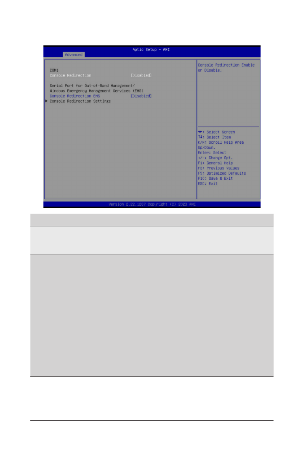
13) BP_1 (HDD Backplane Board Connector)
1 2
2930
2 1
Pin No. Pin No.Denition Denition
1 Reserved 2 BPMI DIN/OUT
3 GND 4 BPMI DOUT/IN
5 BPMI_LOAD 6 GND
7 BPMI_CLK 8 PLD_Program_EN
9 GLED_AMB_N 10 GLED_GRN_N
11 FAN_IRQ_N 12 Reserved
13 BP_SCL 14 GND
15 BP_SDA 16 BP_RST_N
17 SMB_U2_TMP_SCL 18 GND
19 SMB_U2_TMP_SDA 20 I2C_DEV_RST
21 PH_HP_SCL0 22 GND
23 PH_HP_SDA0 24 GND
25 PH_HP_SCL1 26 GND
27 PH_HP_SDA1 28 GND
29 P3V3_AUX 30 P3V3_AUX

- 24 -
Hardware Installation
15) SPI_TPM (Trusted Platform Module Connector)
Trusted Platform Module (TPM) is an international standard for a secure cryptoprocessor, a dedicated
microcontroller designed to secure hardware through integrated cryptographic keys.
Pin No. Pin No.Denition Denition
1 Clock 8 NC
2 P_3V3_AUX 9 NC
3 LPC_RST 10 No Pin
4 NC NC11
5 SPI_MISO 12 GND
6 IRQ_SPI 13 SPI_CS_N
7 SPI_MOSI 14 GND
2 1
14 13
14) COM2 (Serial Port Cable Connector)
The COM header can provide one serial port via an optional COM port cable. For purchasing the optional
COM port cable, please contact the local dealer.
109
21 Pin No. Denition
1 NDCDB#
2 NDSRB#
3 NSINB
4 NRTSB#
5 NSOUTB
6 NCTSB#
7 NDTRB#-
8 NEIB#
9 GND
10 No Pin
- 25 -
Hardware Installation
PinNo. Denition
1 Clock
2 Data
3 GND
4 VCC
16) IPMB (Intelligent Platform Management Bus) Connector
The Intelligent Platform Management Bus Communications Protocol defines a byte-level transport for
transferringIntelligentPlatformManagementInterfaceSpecication(IPMI)messagesbetweenintelligentI2C
devices.
4
1
17) CN_NCSI (NCSI Connector)
Pin No. Pin No.Denition Denition
1 NCSI_CLK 2 GND
3 NCSI_RX_D0 4 GND
5 NCSI_RX_D1 6 GND
7 NCSI_CRS_DV 8 GND
9 NCSI_RX_ER 10 GND
11 P3V3_AUX 12 GND
13 NCSI_TX_D1 14 GND
15 NCSI_TX_D0 16 GND
17 NCSI_TX_EN 18 GND
19 20 P3V3_AUXNCSI_PRESENT
1920
2 1
- 26 -
Hardware Installation
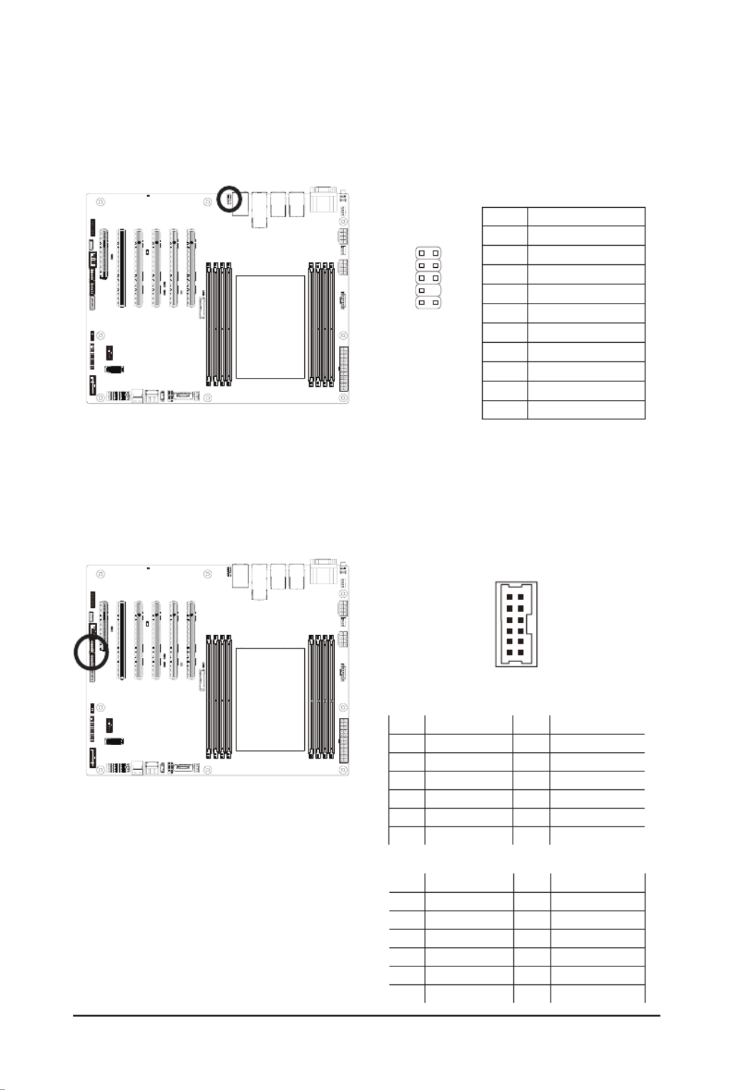
18) F_AUDIO1 (Front Panel Audio Header)
ThefrontpanelaudioheadersupportsIntelHighDenitionaudio(HD).Youmayconnectyourchassis
front panel audio module to this header. Make sure the wire assignments of the module connector match
the pin assignments of the motherboard header. Incorrect connection between the module connector and
the motherboard header will make the device unable to work or even damage it.
PinNo. Denition
1 MIC_L
2 GND
3 MIC_R
4 Power (3.3V)
5 LINE_R
6 GND
7 AUDIO_JD
8 NA
9 LINE_L
10 GND
21
109
19) GPIO_CNT_1/GPIO_CNT_2 (General-Purpose Input/Output Connector)
Pin No. Pin No.Denition Denition
1 SOGP0_1 7 SOGP0_4
2 SOGP1_1 8 SOGP1_4
3 SOGP0_2 9 SMB_CLK
4 SOGP1_2 10 SMB_DATA
5 SOGP0_3 VCC(5V)11
6 SOGP1_3 12 GND
2 1
12 11
GPIO_CNT_1
Pin No. Pin No.Denition Denition
1 SOGP2_1 7 SOGP2_4
2 SOGP3_1 8 SOGP3_4
3 SOGP2_2 9 SMB_CLK
4 SOGP3_2 10 SMB_DATA
5 SOGP2_3 VCC(5V)11
6 SOGP3_3 12 GND
GPIO_CNT_2

- 27 -
Hardware Installation
20) LED_BMC (BMC Firmware Readiness LED)
State Description
On BMCrmwareisinitial
Blink BMCrmwareisready
Off AC loss
21) BAT (Battery Socket)
Thebatteryprovidespowertokeepthevalues(suchasBIOScongurations,date,andtimeinformation)in
the CMOS when the computer is turned off. Replace the battery when the battery voltage drops to a low level,
or the CMOS values may not be accurate or may be lost.
• Always turn off your computer and unplug the power cord before replacing the battery.
• Replace the battery with an equivalent one. Danger of explosion if the battery is replaced with an incorrect
model.
• Contact the place of purchase or local dealer if you are not able to replace the battery by yourself or
uncertain about the battery model.
• Used batteries must be handled in accordance with local environmental regulations.
1
2

- 28 -
Hardware Installation
22) CASE_OPEN (Case Open Intrusion Alert Header)
This motherboard provides a chassis detection feature that detects if the chassis cover has been removed.
This function requires a chassis with chassis intrusion detection design.
Open: Normal Operation (Default)
Closed: Active Chassis Intrusion Alert

- 29 -
Hardware Installation
1-8 Jumper Settings
Clear CMOS
CLR_CMOS
Enable
De ultfa
1
2
3
NCSI_SW
10GbE LAN1
CN_NCSI
SW1
OFF
SW2
OFF
ON OFF
1 2
ON
ME
Recovery
ME_RCVR De ultfa
Enable
1
2
3
BIOS
Recovery
BIOS_RCVR De ultfa
Enable
1
2
3
Password
Clear
BIOS_PWD De ultfa
Enable
3
2
1

- 30 -
BIOS Setup
BIOS (Basic Input and Output System) records hardware parameters of the system in the EFI on the
motherboard.ItsmajorfunctionsincludeconductingthePower-OnSelf-Test(POST)duringsystemstartup,
saving system parameters, loading the operating system etc. The BIOS includes a BIOS Setup program that
allowstheusertomodifybasicsystemcongurationsettingsortoactivatecertainsystemfeatures.Whenthe
power is turned off, the battery on the motherboard supplies the necessary power to the CMOS to keep the
congurationvaluesintheCMOS.
To access the BIOS Setup program, press the <DEL> key during the POST when the power is turned on.
Chapter 2 BIOS Setup
• BIOSashingispotentiallyrisky,ifyoudonotencounteranyproblemswhenusingthecurrent
BIOSversion,it isrecommended that you don't ash the BIOS.To ash the BIOS, do itwith
caution.InadequateBIOSashingmayresultinsystemmalfunction.
• It is recommended that you not alter the default settings (unless you need to) to prevent system
instability or other unexpected results. Inadequately altering the settings may result in system's
failure to boot. If this occurs, try to clear the CMOS values and reset the board to default values.
(Refer to the Exitsectioninthischapterorintroductionsofthebattery/clearingCMOSjumperin
Chapter 1 for how to clear the CMOS values.)
BIOS Setup Program Function Keys
<f><g> Move the selection bar to select the screen
<h><i> Move the selection bar to select an item
<+> Increase the numeric value or make changes
<-> Decrease the numeric value or make changes
<Enter> Execute command or enter the submenu
<Esc> Main Menu: Exit the BIOS Setup program
Submenus: Exit current submenu
<F1> Show descriptions of general help
<F3> Restore the previous BIOS settings for the current submenus
<F9> Load the Optimized BIOS default settings for the current submenus
<F10> Save all the changes and exit the BIOS Setup program

- 31 -
BIOS Setup
Main
This setup page includes all the items of the standard compatible BIOS.
Advanced
This setup page includes all the items of AMI BIOS special enhanced features.
(ex:Autodetectfanandtemperaturestatus,automaticallycongureharddiskparameters.)
Chipset
ThissetuppageincludesallthesubmenuoptionsforconguringthefunctionsofthePlatformController
Hub.
Server Management
Server additional features enabled/disabled setup menus.
Security
Change,set,ordisablesupervisoranduserpassword.Congurationsupervisorpasswordallowsyouto
restrict access to the system and BIOS Setup.
A supervisor password allows you to make changes in BIOS Setup.
A user password only allows you to view the BIOS settings but not to make changes.
Boot
Thissetuppageprovidesitemsforcongurationofthebootsequence.
Save & Exit
Save all the changes made in the BIOS Setup program to the CMOS and exit BIOS Setup. (Pressing
<F10> can also carry out this task.)
Abandon all changes and the previous settings remain in effect. Pressing <Y> to the confirmation
message will exit BIOS Setup. (Pressing <Esc> can also carry out this task.)

- 32 -
BIOS Setup
2-1 The Main Menu
Once you enter the BIOS Setup program, the Main Menu (as shown below) appears on the screen. Use
arrow keys to move among the items and press <Enter> to accept or enter other sub-menu.
Main Menu Help
The on-screen description of a highlighted setup option is displayed on the bottom line of the Main Menu.
Submenu Help
While in a submenu, press <F1> to display a help screen (General Help) of function keys available for the
menu. Press <Esc> to exit the help screen. Help for each item is in the Item Help block on the right side of
the submenu.
• When the system is not stable as usual, select the item to set your system to Restore Defaults
its defaults.
• The BIOS Setup menus described in this chapter are for reference only and may differ by BIOS
version.

- 33 -
BIOS Setup
Parameter Description
BIOS Information
ProjectName Displaystheprojectnameinformation.
ProjectVersion Displays version number of the BIOS setup utility.
Build Date and Time Displays the date and time when the BIOS setup utility was created.
BMC Information(Note1)
BMC Firmware Version(Note1) DisplaysBMCrmwareversioninformation.
Processor Information
CPU Brand String/ Max CPU Speed
/ CPU Signature / Processor Core /
Microcode Patch
Displays the technical information for the installed processor(s).
Platform Information
Processor/ PCH/ RC Revision Displays the information of the installed processor(s) and PCH.
Memory Information(Note2)
Total Memory Displays the total memory size of the installed memory.
Usable Memory Displays the usable memory size of the installed memory.
(Note1)
Functions available on selected models.
(Note2) This section will display capacity and frequency information of the memory that the customer has
installed.

- 34 -
BIOS Setup
Parameter Description
Memory Frequency Displays the frequency information of the installed memory.
Onboard LAN Information(Note3)
LAN# MAC Address Displays LAN MAC address information.
System Date Sets the date following the weekday-month-day-year format.
System Time Sets the system time following the hour-minute-second format.
(Note3) The number of LAN ports listed will depend on the motherboard / system model.

- 35 -
BIOS Setup
2-2 Advanced Menu
TheAdvancedMenudisplayssubmenuoptionsforconguringthefunctionofvarioushardwarecomponents.
Select a submenu item, then press <Enter> to access the related submenu screen.

- 36 -
BIOS Setup
2-2-1 Trusted Computing
Parameter Description
Conguration
TPM v1.2 Support
Enable/Disable BIOS support for security device. OS will not show
security device. TCG EFI protocol and INT1A interface will not be
available.
Options available: Disable, Enable. Default setting is .Enable
- 37 -
BIOS Setup
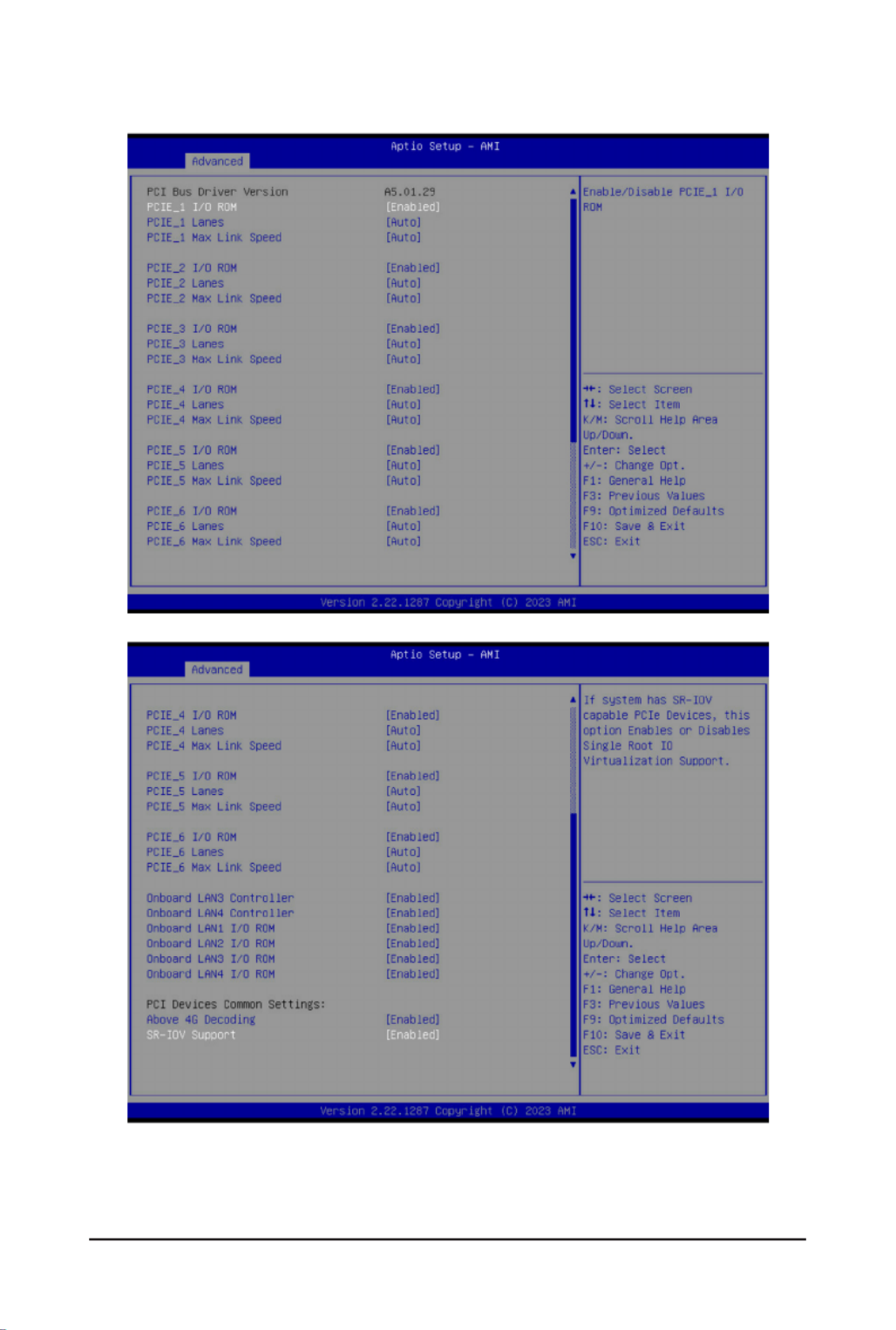
2-2-2 Serial Port Console Redirection
(Note) Advanceditemspromptwhenthisitemisdened.
Parameter Description
COM1 Console
Redirection(Note)
Console redirection enables the users to manage the system from a
remote location.
Options available: Enabled, Disabled. Default setting is .Disabled
COM1 Console Redirection
Settings
Press[Enter]tocongureadvanceditems.
Please note that this item is congurable when COM1 Console
Redirection is set to Enabled.
Terminal Type
– Selects a terminal type to be used for console redirection.
– Options available: VT100, VT100PLUS, VT-UTF8, ANSI. Default
setting is .VT100PLUS
Bits per second
– Selects the transfer rate for console redirection.
– Options available: 9600, 19200, 38400, 57600, 115200. Default
setting is 115200.
Data Bits
– Selects the number of data bits used for console redirection.
– Options available: 7, 8. Default setting is .8

- 38 -
BIOS Setup
Parameter Description
COM1 Console Redirection
Settings (continued)
Parity
– A parity bit can be sent with the data bits to detect some
transmission errors.
– Even: parity bit is 0 if the num of 1's in the data bits is even.
– Odd: parity bit is 0 if num of 1's in the data bits is odd.
– Mark: parity bit is always 1. Space: Parity bit is always 0.
– Mark and Space Parity do not allow for error detection.
– Options available: None, Even, Odd, Mark, Space. Default setting
is .None
Stop Bits
– Stop bits indicate the end of a serial data packet. (A start bit
indicates the beginning). The standard setting is 1 stop bit.
Communication with slow devices may require more than 1 stop
bit.
– Options available: 1, 2. Default setting is .1
Flow Control
– Flowcontrolcanpreventdatalossfrombufferoverow.When
sending data, if the receiving buffers are full, a 'stop' signal can
besenttostopthedataow.Oncethebuffersareempty,a'start'
signalcanbesenttore-starttheow.Hardwareowcontroluses
two wires to send start/stop signals.
– Options available: None, Hardware RTS/CTS. Default setting is
None.
VT-UTF8 Combo Key Support
– Enable/Disable the VT-UTF8 Combo Key Support.
– Options available: Enabled, Disabled. Default setting is .Enabled
Recorder Mode
– When this mode enabled, only texts will be send. This is to capture
Terminal data.
– Options available: Enabled, Disabled. Default setting is .Disabled
Resolution 100x31
– Enable/Disable extended terminal resolution.
– Options available: Enabled, Disabled. Default setting is .Enabled
Putty KeyPad
– Selects Function Key and KeyPad on Putty.
– Options available: VT100, LINUX, XTERMR6, SC0, ESCN, VT400.
Default setting is .VT100

- 39 -
BIOS Setup
Parameter Description
Serial Port for Out-of-Band
Management / Windows
Emergency Management
Services (EMS) Console
Redirection(Note)
EMSconsoleredirectionallowstheusertocongureConsoleRedirection
Settings to support Out-of-Band Serial Port management.
Options available: Enabled, Disabled. Default setting is .Disabled
Serial Port for Out-of-Band
EMS Console Redirection
Settings
Press[Enter]tocongureadvanceditems.
Please note that this item is congurable when Serial Port for Out-of-
Band Management EMS Console Redirection is set to Enabled.
Out-of-Band Mgmt Port
– Microsoft Windows Emergency Management Service (EMS) allows
for remote management of a Windows Server OS through a serial
port.
– Default setting is .COM1
Terminal Type EMS
– Selects a terminal type to be used for console redirection.
– Options available: VT100, VT100PLUS, VT-UTF8, ANSI. Default
setting is .VT100PLUS
Bits per second EMS
– Selects the transfer rate for console redirection.
– Options available: 9600, 19200, 57600, 115200. Default setting is
115200.
Flow Control EMS
– Flowcontrolcanpreventdatalossfrombufferoverow.When
sending data, if the receiving buffers are full, a 'stop' signal can
besenttostopthedataow.Oncethebuffersareempty,a'start'
signalcanbesenttore-starttheow.Hardwareowcontroluses
two wires to send start/stop signals.
– Options available: None, Hardware RTS/CTS, Software Xon/Xoff.
Default setting is .None

- 40 -
BIOS Setup
2-2-3 SIO Conguration
Parameter Description
AMI SIO Driver Version Displays the AMI SIO driver version information.
Super IO Chip Logical
Device(s)Conguration
[*Active*] Serial Port
Press[Enter]tocongureadvanceditems.
Use This Device
– Whenset to Enabled allowsyou to congure the serial port settings.
WhensettoDisabled,displaysnocongurationfortheserialport.
– Options available: Enabled, Disabled. Default setting is .Enabled
Logical Device Settings/Current:
– Displays the serial port base I/O address and IRQ.
Possible:
– CongurestheserialportbaseI/OaddressandIRQ.
Use Automatic Settings
IO=3F8h; IRQ=4; DMA;
IO=3F8h; IRQ=4; DMA;
IO=2F8h; IRQ=4; DMA;
IO=3E8h; IRQ=4; DMA;
IO=2E8h; IRQ=4; DMA;
Default setting is .Use Automatic Settings
- 41 -
BIOS Setup
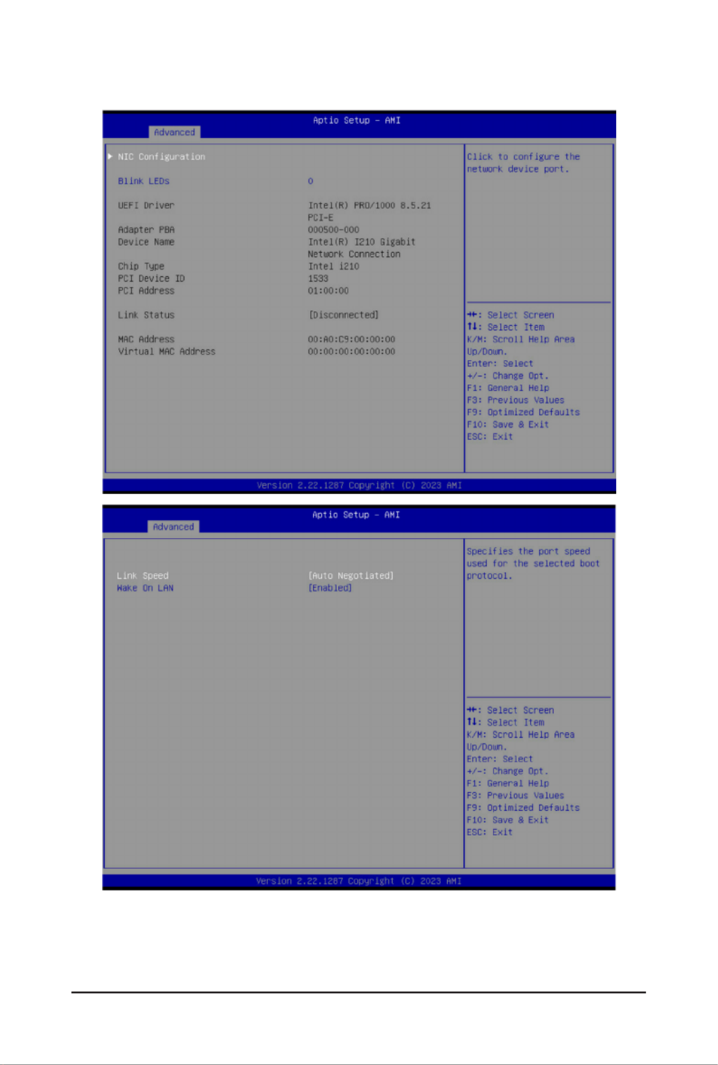
2-2-4 PCI Subsystem Settings

- 42 -
BIOS Setup
Parameter Description
PCI Bus Driver Version Displays the PCI Bus Driver version information.
PCIE_# I/O ROM(Note1)
When enabled, this setting will initialize the device expansion
ROM for the related PCI-E slot.
Options available: Enabled, Disabled. Default setting is .Enabled
PCIE_# Lanes(Note1) Change the PCIe lanes. Default setting is .Auto
PCIE_#_Max Link Speed(Note1)
CongurePCIemaxlinkspeed.
Options available: Auto, Gen1, Gen2, Gen3, Gen4, Gen5.
Default setting is .Auto
Onboard LAN1# Controller(Note2) Enable/Disable the onboard LAN controller.
Options available: Enabled, Disabled. Default setting is .Enabled
Onboard LAN# I/O ROM(Note2)
Enable/Disable the onboard LAN devices, and initializes device
expansion ROM.
Options available: Enabled, Disabled. Default setting is .Enabled
PCI Devices Common Settings
Above 4G Decoding
Enable/Disable memory mapped I/O to 4GB or greater address
space (Above 4G Decoding).
Options available: Enabled, Disabled. Default setting is .Enabled
SR-IOV Support
If the system has SR-IOV capable PCIe devices, this item
Enable/Disable Single Root IO Virtualization Support.
Options available: Enabled, Disabled. Default setting is .Enabled
(Note1) This section is dependent on the available PCIe Slot.
(Note2) This section is dependent on the available LAN controller.

- 43 -
BIOS Setup
2-2-5 USB Conguration
(Note) This item is present only if you attach USB devices.
Parameter Description
USBConguration
USB Devices: Displays the USB devices connected to the system.
XHCI Hand-off Enable/Disable the XHCI (USB 3.0) Hand-off support.
Options available: Enabled, Disabled. Default setting is .Enabled
USB Mass Storage Driver
Support(Note)
Enable/Disable the USB Mass Storage Driver Support.
Options available: Enabled, Disabled. Default setting is .Enabled
Port 60/64 Emulation
Enables the I/O port 60h/64h emulation support. This should be
enabled for the complete USB Keyboard Legacy support for non-
USB aware OSes.
Options available: Enabled, Disabled. Default setting is .Enabled

- 44 -
BIOS Setup
2-2-6 Network Stack Conguration
Parameter Description
Network Stack Enable/Disable the UEFI network stack.
Options available: Enabled, Disabled. Default setting is .Enabled
Ipv4 PXE Support Enable/Disable the Ipv4 PXE feature.
Options available: Enabled, Disabled. Default setting is .Enabled
Ipv4 HTTP Support Enable/Disable the Ipv4 HTTP feature.
Options available: Enabled, Disabled. Default setting is .Disabled
Ipv6 PXE Support Enable/Disable the Ipv6 PXE feature.
Options available: Enabled, Disabled. Default setting is .Disabled
Ipv6 HTTP Support Enable/Disable the Ipv6 HTTP feature.
Options available: Enabled, Disabled. Default setting is .Disabled
PXE boot wait time Wait time in seconds to press ESC key to abort the PXE boot.
Press the <+> / <-> keys to increase or decrease the desired values.
Media detect count Number of times the presence of media will be checked.
Press the <+> / <-> keys to increase or decrease the desired values.

- 45 -
BIOS Setup
2-2-7 Post Report Conguration
Parameter Description
PostReportConguration
Error Message Report
Post Error Message Enable/Disable the POST Error Message support.
Options available: Enabled, Disabled. Default setting is .Enabled
Halt On Options available: No Error, All Error. Default setting is .No Error

- 46 -
BIOS Setup
2-2-8 NVMe Conguration
Parameter Description
NVMeConguration Displays the NVMe devices connected to the system.
NVMe OPROM Select Options available: BIOS Build-In, NVMe Device. Default setting is BIOS
Build-In.
NVMe LED Control
Enable/Disable allow user control NVMe LED. It only available the NVMe
device direct connect to CPU.
Options available: Disable, Enable. Default setting is .Disable

- 47 -
BIOS Setup
2-2-9 Chipset Conguration
Parameter Description
Restore on AC Power Loss
(Note)
Denesthepowerstatetoresumetoafterasystemshutdownthatis
due to an interruption in AC power. When set to Last State, the system
will return to the active power state prior to shutdown. When set to
Power Off, the system remains off after power shutdown.
Optionsavailable:LastState,PowerOff,PowerOn,Unspecied.The
default setting depends on the BMC setting.
P2P Bridge IO Size SpeciesP2PBridgeIOalignedtothesize.
Options available: 0x100, 0x150, 0x1000. Default setting is .0x1000
SATA HDD Security Frozen Enable/Disable this item to send freeze lock command to SATA HDD.
Options available: Enabled, Disabled. Default setting is .Enabled
NVMe SSD Security Frozen Attempt to send freeze lock command to NVMe SSDs during boot.
Options available: Enabled, Disabled. Default setting is .Enabled
Chassis Opened Warning
Enable/Disable the chassis intrusion alert function.
Options available: Enabled, Disabled, Clear. Default setting is
Disabled.
(Note) When the power policy is controlled by BMC, please wait for 15-20 seconds for BMC to save the
last power state.

- 48 -
BIOS Setup
2-2-10 Tls Auth Conguration
Parameter Description
ServerCAConguration
Press[Enter]forcongurationofadvanceditems.
Enroll Cert
–Press[Enter]toenrollacerticate
• Enroll Cert Using File
• Cert GUID
Input digit character in 1111111-2222-3333-4444-1234567890ab
format.
– Commit Changes and Exit
– Discard Changes and Exit
Delete Cert
ClientCertConguration Press[Enter]forcongurationofadvanceditems.

- 49 -
BIOS Setup
2-2-11 iSCSI Conguration
Parameter Description
Attempt Priority
Press[Enter]congureadvanceditems.
Attempt Priority
– Use arrow keys to select the attempt, then press +/- keys to move
the attempt up/down in the attempt order list.
Commit Changes and Exit
HostiSCSIConguration
Press[Enter]tocongureadvanceditems.
iSCSI Initiator Name
– Only IQN format is accepted. Range: from 4 to 223
Add an Attempt
Delete Attempts
Change Attempt Order
- 50 -
BIOS Setup
2-2-12 Intel(R) i210 Gigabit Network Connection

- 51 -
BIOS Setup
Parameter Description
NICConguration
Press[Enter]tocongureadvanceditems.
Link Speed
– Allowsforautomaticlinkspeedadjustment.
– Options available: Auto Negotiated, 10 Mbps Half, 10 Mbps Full,
100 Mbps Half, 100 Mbps Full. Default setting is .Auto Negotiated
Wake On LAN
– EnablespoweronofthesystemviaLAN.Notethatconguring
Wake on LAN in the operating system does not change the value of
this setting, but does override the behavior of Wake on LAN in OS
controlled power states.
– Options available: Enabled, Disabled. Default setting is .Enabled
Blink LEDs IdentiesthephysicalnetworkportbyblinkingtheassociatedLED.
Pressthenumerickeystoadjustdesiredvalues(upto15seconds).
UEFI Driver DisplaysthetechnicalspecicationsfortheNetworkInterfaceController.
Adapter PBA DisplaysthetechnicalspecicationsfortheNetworkInterfaceController.
Device Name DisplaysthetechnicalspecicationsfortheNetworkInterfaceController.
Chip Type DisplaysthetechnicalspecicationsfortheNetworkInterfaceController.
PCI Device ID DisplaysthetechnicalspecicationsfortheNetworkInterfaceController.
PCI Address DisplaysthetechnicalspecicationsfortheNetworkInterfaceController.
Link Status DisplaysthetechnicalspecicationsfortheNetworkInterfaceController.
MAC Address DisplaysthetechnicalspecicationsfortheNetworkInterfaceController.
Virtual MAC Address DisplaysthetechnicalspecicationsfortheNetworkInterfaceController.

- 52 -
BIOS Setup
2-2-13 VLAN Conguration
Parameter Description
EnterCongurationMenu
Press[Enter]tocongureadvanceditems.
Create new VLAN
VLAN ID
– Sets VLAN ID for a new VLAN or an existing VLAN.
– Press the <+> / <-> keys to increase or decrease the desired values.
– The valid range is from 0 to 4094.
Priority
– Sets 802.1Q Priority for a new VLAN or an existing VLAN.
– Press the <+> / <-> keys to increase or decrease the desired values.
– The valid range is from 0 to 7.
Add VLAN
– Press [Enter] to create a new VLAN or update an existing VLAN.
ConguredVLANList
Remove VLAN
– Press [Enter] to remove an existing VLAN.

- 53 -
BIOS Setup
2-2-14 Broadcom BCM57416 NetXtreme-E 10GBASE-T RDMA Ethernet Controller
Parameter Description
Firmware Image Menu Press[Enter]toviewrmwareimageinformation.
DeviceCongurationMenu
Press[Enter]tocongureadvanceditems.
Multi-Function Mode
– CongurestheNICHardwareMode.
– Options available: SF, NPAR 1.0. Default setting is .SF
SR-IOV
– Enable/Disable Single Root I/O Virtualization.
– Options available: Enabled, Disabled. Default setting is .Disabled
Number of MSI-X Vectors per VF
– ConguresthenumberofMSI-XVectorsperVF(0-128).
– Default setting is .16
Maximum Number of PF MSI-X Vectors
– ConguresthemaximumnumberofPFMSI-XVectors(0-512per
controller).
– Default setting is .74
EnergyEfcientEthernet
– Enable/DisableEnergyEfcientEthernetoperation.
– Options available: Enabled, Disabled. Default setting is .Disabled
Operational Link Speed
– Conguresthelinkspeedsettingtobeusedasthedefaultlinkspeed
for the selected port.
– Default setting is .AutoNeg

- 54 -
BIOS Setup
Parameter Description
DeviceCongurationMenu
(continued)
Support RDMA
– Enable/Disable RDMA support for this port.
– Options available: Enabled, Disabled. Default setting is .Disabled
DCB Protocol
– Enable/Disable DCB protocol.
– Options available: Disabled, Enabled (IEEE only), CEE (only), Both
(IEEE preferred with fallback to CEE). Default setting is .Disabled
LLDP nearest bridge
– Enable/Disable LLDP nearest bridge state.
– Options available: Enabled, Disabled. Default setting is .Enabled
Default EVB Mode
– ConguresthedefaultEdgeVirtualBridgingmode.
– Options available: VEB, VEPA, None. Default setting is .VEB
Enable PME Capability
– Enable/Disable PME Capability support.
– Options available: Enabled, Disabled. Default setting is .Enabled
FlowOfoad
– Options available: Enabled, Disabled. Default setting is .Disabled
Live Firmware Upgrade
– Options available: Enabled, Disabled. Default setting is .Disabled
Adapter Error Recovery
– Options available: Enabled, Disabled. Default setting is .Disabled
MBACongurationMenu
Press[Enter]tocongureadvanceditems.
Option ROM
– Enable/Disable Boot Option ROM.
– Options available: Enabled, Disabled. Default setting is .Enabled
Legacy Boot Protocol
– Selects non-UEFI Boot Protocol: Preboot Execution Environment
(PXE)/iSCSI.
– Options available: PXE, iSCSI, NONE. Default setting is .PXE
Boot Strap Type
– Selects the boot strap type. Options available: Auto Detect, BBS,
Int 18h, Int 19h. Default setting is .Auto Detect
Hide Setup Prompt
– CongureswhethertheSetupPromptisdisplayedduringROM
initialization.
– Options available: Enabled, Disabled. Default setting is .Disabled
Setup Key Stroke
– Congureskeystrokestoinvokethecongurationmenu.
– Options available: Ctrl-S, Ctrl-B. Default setting is .Ctrl-S
Banner Message Timeout
– Selects the timeout value. (0 defaults to 4 seconds, 15 is no delay,
1-14 is timeout value in seconds)
– Default setting is .5

- 55 -
BIOS Setup
Parameter Description
MBACongurationMenu
(continued)
Pre-boot Wake On LAN
– ConguresPre-bootWakeonLAN(WOL).
– Options available: Enabled, Disabled. Default setting is .Enabled
VLAN Mode
– ConguresthevirtualLAN(VLAN)mode.
– Options available: Enabled, Disabled. Default setting is .Disabled
VLAN ID
– CongurestheVLANID(1…4094).
– This item is available only when VLAN Mode is Enabled.
Boot Retry Count
– Selects the number of boot retries.
– Options available: No Retry, 1 Retry, 2 Retries, 3 Retries, 4 Retries,
5Retries,6Retries,IndeniteRetries.Defaultsettingis5 Retries.
iSCSIBootConguration
Menu
Press[Enter]tocongureadvanceditems.
Blink LEDs IdentiesthephysicalnetworkportbyblinkingtheassociatedLED.
Pressthenumerickeystoadjustdesiredvalues.
Link Status Speciesthelinkstatusoftheport.
Physical Link Speed DisplaysthetechnicalspecicationsfortheNetworkInterfaceController.
Chip Type DisplaysthetechnicalspecicationsfortheNetworkInterfaceController.
PCI Device ID DisplaysthetechnicalspecicationsfortheNetworkInterfaceController.
Bus:Device:Function DisplaysthetechnicalspecicationsfortheNetworkInterfaceController.
Permanent MAC Address Displays the MAC address of the Ethernet controller.
Virtual MAC Address Displays the virtual MAC address of the Ethernet controller.
Restore Defaults Resets the adapter to factory defaults.

- 56 -
BIOS Setup
2-2-14-1 iSCSI Boot Conguration Menu
Parameter Description
iSCSI General Parameters
Press[Enter]tocongureadvanceditems.
TCP/IP Parameters via DHCP
– Acquires TCP/IP Parameters via DHCP.
– Options available: Enabled, Disabled. Default setting is .Enabled
IPAutoconguration
– Auto-congurestheIPconguration.
– Options available: Enabled, Disabled. Default setting is .Enabled
iSCSI Parameters via DHCP
– Acquires iSCSI Parameters via DHCP.
– Options available: Enabled, Disabled. Default setting is .Disabled
CHAP Authentication
– Enable/Disable the CHAP authentication.
– Options available: Enabled, Disabled. Default setting is .Disabled
Boot to iSCSI Target
– Enable/Disable booting to iSCSI target after log-on.
– Options available: Enabled, Disabled, One Time Disabled. Default
setting is .Enabled
DHCP Vendor ID
– CongurestheDHCPvendorID(upto32characterslong).
Link Up Delay Time
– Conguresthelinkupdelaytimeinseconds(0-225).

- 57 -
BIOS Setup
Parameter Description
iSCSI General Parameters
(continued)
Use TCP Timestamp
– Enable/Disable the TCP timestamp.
– Options available: Enabled, Disabled. Default setting is .Disabled
Target as First HDD
– Enable/Disabletargetappearsasrstharddiskdrive(HDD)inthe
system.
– Options available: Enabled, Disabled. Default setting is .Disabled
LUN Busy Retry Count
– Conguresthenumberofretriesin2secondintervalswhenLUNis
busy (0-60).
– Default setting is .0
IP Version
– Displays the IP version supported. Modifying this parameter will reset
allIP-relatedelds.
– Options available: IPv4, IPv6. Disabled. Default setting is .IPv4
iSCSI Initiator Parameters
Press[Enter]tocongureadvanceditems.
IP Address
– CongurestheinitiatorIPaddress.
Subnet Mask
– CongurestheIPsubnetmask.
Default Gateway
– ConguresthedefaultgatewayIPaddress.
Primary DNS
– CongurestheprimaryDNSIPaddress.
Secondary DNS
– ConguresthesecondaryDNSIPaddress.
iSCSI Name
– CongurestheiSCSIname.
CHAP ID
– CongurestheChallenge-HandshakeAuthenticationProtocol
(CHAP) ID (up to 128 characters in length).
CHAP Secret
– ConguretheChallenge-HandshakeAuthenticationProtocol
(CHAP) Secret (12 to 16 characters in length).
iSCSI First/Second Target
Parameters
Press[Enter]tocongureadvanceditems.
Connect
– Enable/Disable the target establishment.
– Options available: Enabled, Disabled. Default setting is .Disabled
IP Address
– CongurestheTargetIPaddress.
TCP Port
– CongurestheTargetTCPportnumber(1-65535).

- 58 -
BIOS Setup
Parameter Description
iSCSI First/Second Target
Parameters (continued)
Boot LUN
– CongurestheTargetbootLUNnumber(0-255).
iSCSI Name
– CongurestheiSCSIname.
CHAP ID
– CongurestheChallenge-HandshakeAuthenticationProtocol
(CHAP) ID (up to 128 characters in length).
CHAP Secret
– ConguretheChallenge-HandshakeAuthenticationProtocol
(CHAP) Secret (12 to 16 characters in length).
Secondary Device
Press[Enter]tocongureadvanceditems.
Secondary Device
– Inputs the secondary device MAC address.
Use Independent Target Portal
– Use Independent target portal when multipath I/O is enabled.
– Options available: Enabled, Disabled. Default setting is .Disabled
Use Independent Target Name
– Use Independent target name when multipath I/O is enabled.
– Options available: Enabled, Disabled. Default setting is .Disabled

- 59 -
BIOS Setup
2-2-15 VLAN Conguration
Parameter Description
EnterCongurationMenu
Press[Enter]tocongureadvanceditems.
Create new VLAN
VLAN ID
– Sets VLAN ID for a new VLAN or an existing VLAN.
– Press the <+> / <-> keys to increase or decrease the desired values.
– The valid range is from 0 to 4094.
Priority
– Sets 802.1Q Priority for a new VLAN or an existing VLAN.
– Press the <+> / <-> keys to increase or decrease the desired values.
– The valid range is from 0 to 7.
Add VLAN
– Press [Enter] to create a new VLAN or update an existing VLAN.
ConguredVLANList
Remove VLAN
– Press [Enter] to remove an existing VLAN.

- 60 -
BIOS Setup
2-2-16 Driver Health
Parameter Description
Driver Health Displays driver health status of the devices/controllers if installed

- 61 -
BIOS Setup
2-3 Chipset Menu
ChipsetSetupmenudisplayssubmenuoptionsforconguringthefunctionofPlatformControllerHub(PCH
Select a submenu item, then press <Enter> to access the related submenu screen.
- 62 -
BIOS Setup
2-3-1 Processor Conguration

- 63 -
BIOS Setup
Parameter Description
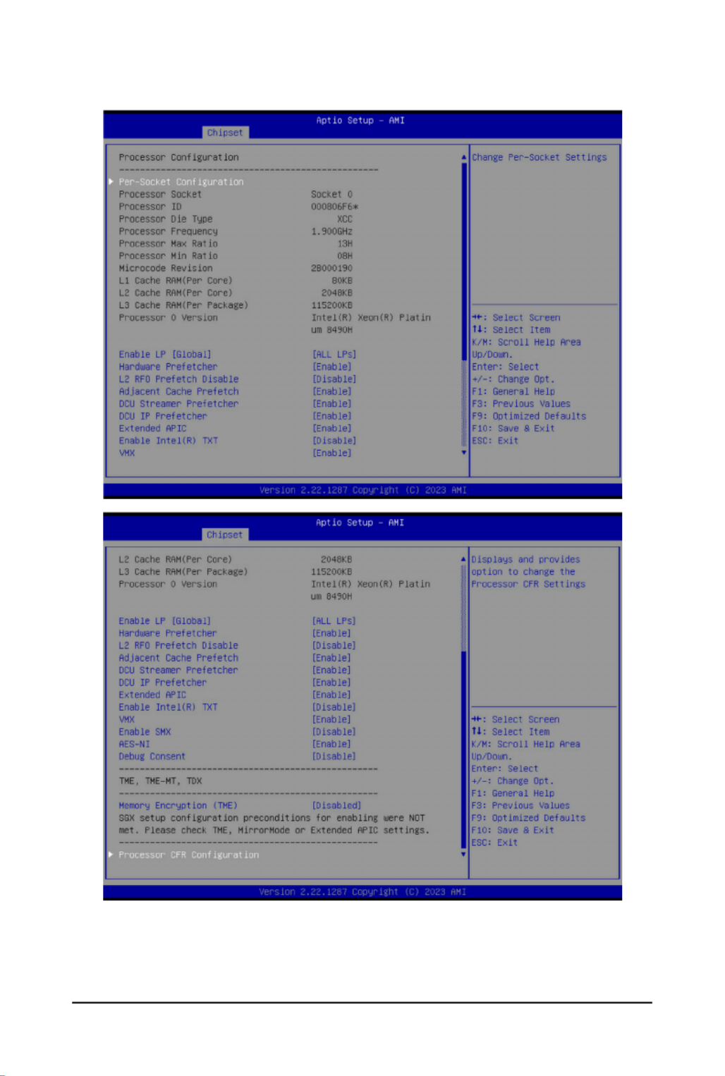
ProcessorConguration
Pre-SocketConguration
Press[Enter]tocongureadvanceditems.
CPUSocket0Conguration
– Core Disable Bitmap(Hex)
• Number of Cores to enable. 0 means all cores. FFFFFFF
means to disable all cores. The maximum value depends on
the number of CPUs available. Press the numeric keys to
adjustdesiredvalues.
Processor Socket / Processor ID
/ Processor Die Type / Processor
Frequency / Processor Max Ratio
/ Processor Min Ratio / Microcode
Revision / L1 Cache RAM(Per
Core) / L2 Cache RAM(Per Core)
/ L3 Cache RAM(Per Package) /
Processor # Version
Displaysthetechnicalspecicationsfortheinstalledprocessor(s).
Enable LP [Global]
Enables Logical processor (Software Method to Enable/Disable Logical
Processor threads).
Options available: ALL LPs, Single LP. Default setting is .ALL LPs
Hardware Prefetcher Select whether to enable the speculative prefetch unit of the processor.
Options available: Enable, Disable. Default setting is .Enable
L2 RF0 Prefetch Disable Options available: Enable, Disable. Default setting is .Disable
AdjacentCachePrefetch
When enabled, cache lines are fetched in pairs. When disabled, only
the required cache line is fetched.
Options available: Enable, Disable. Default setting is .Enable
DCU Streamer Prefetcher Enable/Disable DCU streamer prefetcher.
Options available: Enable, Disable. Default setting is .Enable
DCU IP Prefetcher Enable/Disable DCU IP Prefetcher.
Options available: Enable, Disable. Default setting is .Enable
Extended APIC
Enable/Disable extended APIC support. Note: The VT-d will be enabled
automatically when x2APIC is enabled.
Options available: Enable, Disable. Default setting is Enable.
Enable Intel(R) TXT Enable/Disable the Intel Trusted Execution Technology support function.
Options available: Enable, Disable. Default setting is Disable.
VMX
Enable/Disable the Vanderpool Technology. This will take effect after
rebooting the system.
Options available: Enable, Disable. Default setting is .Enable
Enable SMX Enable/Disable the Safer Mode Extensions (SMX) support function.
Options available: Enable, Disable. Default setting is .Disable
AES-NI Enable/Disable the AES-NI support.
Options available: Enable, Disable. Default setting is .Enable
Debug Consent Options available: Enable, Disable. Default setting is .Disable

- 64 -
BIOS Setup
Parameter Description
Memory Encryption (TME)
(Note) Enable/Disable memory encryption (TME).
Options available: Enabled, Disabled. Default setting is .Disabled
Total Memory Encryption
Multi-Tenant (TME-MT) Options available: Enabled, Disabled. Default setting is .Disabled
ProcessorCFRConguration
Press[Enter]tocongureadvanceditems.
Provision S3M CFR
– Options available: Disable, Enable. Default setting is .Enable
Manual Commit S3M FW CFR
– Options available: Disable, Enable, Auto. Default setting is Auto.
Provision PUcode CFR
– Options available: Disable, Enable. Default setting is .Enable
Manual Commit PUcode CFR
– Options available: Enable, Disable, Auto. Default setting is Auto.
Socket0 CFR Revision Info
– Displays CFR Revision information of the socket.
(Note) Advanceditemspromptwhenthisitemisdened.
- 65 -
BIOS Setup
2-3-2 Common RefCode Conguration
Parameter Description
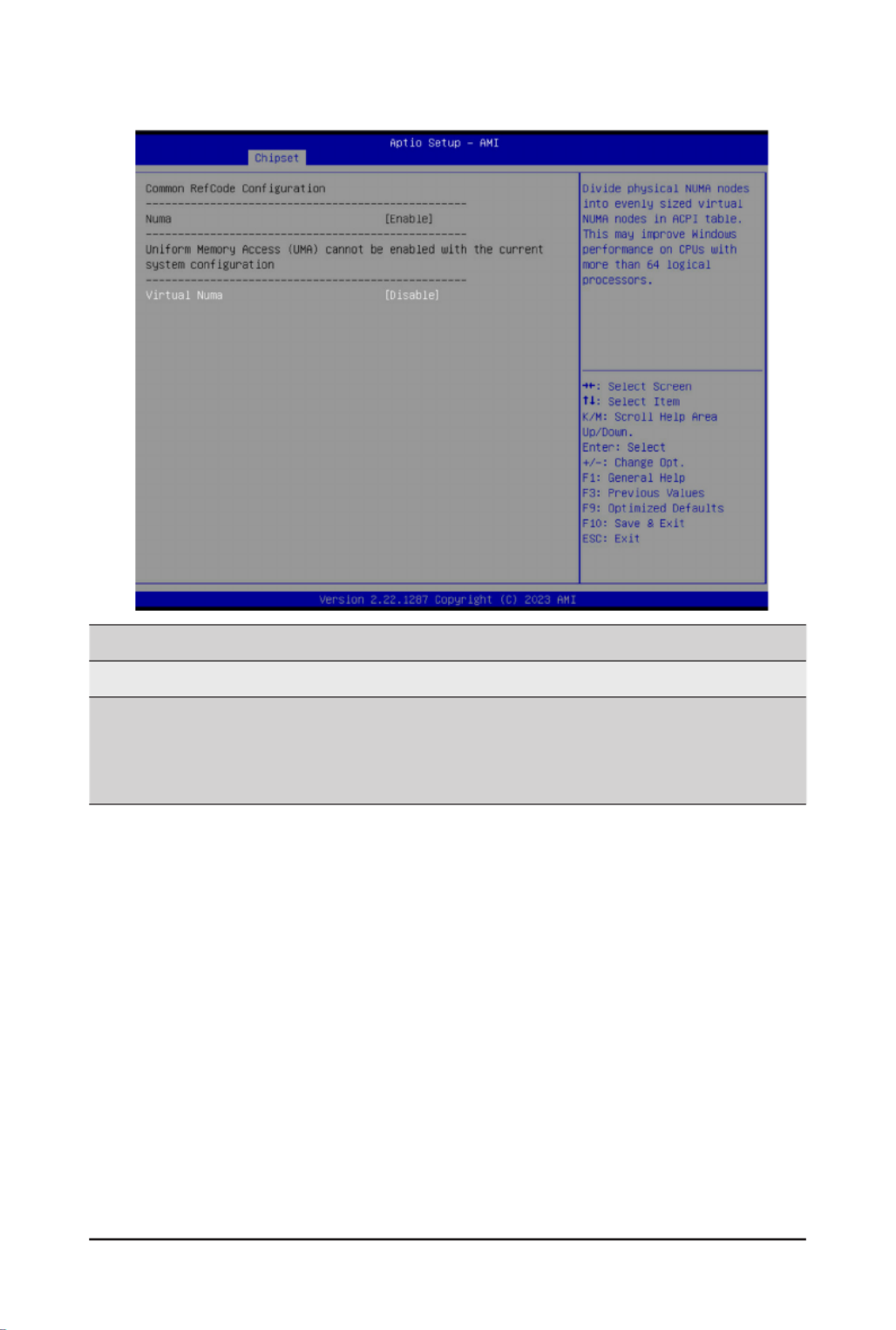
CommonRefCodeConguration
Virtual Numa
Divide physical NUMA nodes into evenly sized virtual NUMA nodes
in ACPI table. This may improve Windows performance on CPUs
with more than 64 logical processors.
Options available: Enable, Disable. Default setting is .Disable

- 66 -
BIOS Setup
2-3-3 UPI Conguration

- 67 -
BIOS Setup
Parameter Description
UPIGeneralConguration
Press[Enter]tocongureadvanceditems.
UPI Status
– Press [Enter] to view the Uncore status.
Link Frequency Select
– Selects the UPI link frequency.
– Options available: 12.8GT/s, 14.4GT/s, 16.0GT/s, Auto, Use Per Link
Setting. Default setting is .Auto
SNC
– Enable/Disable Sub NUMA Cluster function.
– Options available: Auto, Disable, Enable SNC2 (2-clusters), Enable
SNC4 (4-clusters). Default setting is .Auto
Stale AtoS
– Enable/Disable Stale A to S directory optimization.
– Options available: Disable, Enable, Auto. Default setting is .Auto
LLC dead line alloc
– Enable/DisablelldeadlinesinLLC.
– Options available: Disable, Enable, Auto. Default setting is .Enable
MMIO High Base
– Options available: 56T, 40T, 32T, 24T, 16T, 4T, 2T, 1T, 512G, 3584T.
Default setting is .32T
MMIO High Granularity Size
– Selects the allocation size used to assign mmioh resources.
– Options available: 1G, 4G, 16G, 64G, 256G, 1024G. Default setting is
64G.
Limit CPU PA to 46 bits
– Limit CPU physical address to 46 bits to support older Hyper-V. If
enabled, automatically disables TME-MT.
– Options available: Disable, Enable. Default setting is .Disable

- 68 -
BIOS Setup
2-3-4 Memory Conguration
Parameter Description
Integrated Memory Controller (iMC)
Enforce DDR Memory Frequency POR
When set to Enable, the system enforces Plan Of Record restrictions
for DDR frequency programming.
Options available: POR, Disable. Default setting is .POR
Memory Frequency
Conguresthemaximummemoryfrequency.IfEnforcePORis
disabled, user will be able to run at higher frequencies than the
memory support (limited by processor support).
Default setting is .Auto
Enable ADR
Enables the detecting and enabling of ADR (Asynchronous DRAM
Refresh) function.
Options available: Enable, Disable. Default setting is .Enable
Legacy ADR Mode Enable/Disable the Legacy ADR Mode.
Options available: Enable, Disable, Auto. Default setting is .Auto
Minimum System Memory Size Congurestheminimummemorysize.
Options available: 2GB, 4GB, 6GB, 8GB. Default setting is .2GB
ADR Data Save Mode
SpeciestheDataSaveModeforADR.BatterybackedorType01
NVDIMM.
Options available: Disable, Batterybacked DIMMs, NVDIMMs, Copy
to Flash. Default setting is .NVDIMMs
Assert ADR on Reset Enable/Disable Assert ADR on Reset.
Options available: Enabled, Disabled. Default setting is .Disabled

- 69 -
BIOS Setup
Parameter Description
Assert ADR on S5 Enable/Disable Assert ADR on S5.
Options available: Enabled, Disabled. Default setting is .Disabled
Get Memory Timing Auto is the detected SPD value and use it, otherwise use BIOS Build-in.
Options available: Auto, BIOS Build-in. Default setting is .BIOS Build-in
Memory Topology Press [Enter] to view memory topology with DIMM population
information.
Memory Map
Press[Enter]tocongureadvanceditems.
Volatile Memory Mode
– Selects 1LM or 2LM mode for volatile memory.
– Options available: 1LM, 2LM. Default setting is .2LM
MemoryRASConguration
Press[Enter]tocongureadvanceditems.
Mirror Mode
(Note)
– Mirror Mode will set entire 1LM memory in system to be
mirrored, consequently reducing the memory capacity by half.
Enables the Mirror Mode will disable the XPT Prefetch.
– Options available: Disabled, Full Mirror Mode, Partial Mirror
Mode. Default setting is .Disabled
Partial Mirror 1 Size (GB)
– Selects multiplier of 1GB for the size of the SAD to be created.
Correctable Error Threshold
– Correctable Error Threshold (0x01-0x7fff) used for sparing, and
leaky bucket.
– Press the <+> / <-> keys to increase or decrease the desired
values.
Trigger SW Error Threshold
(Note)
– Enable/Disable Sparing trigger SW Error Match Threshold.
– Options available: Disabled, Enabled. Default setting is
Disabled.
SW Per Bank Threshold
– SW Per Bank Threshold (1-0x7FFF) used for DDR bank level
error.
– Press the <+> / <-> keys to increase or decrease the desired
values.
SW Correctable Error Time Window
– SW Correctable Error time window based interface in hour (0-24).
– Press the <+> / <-> keys to increase or decrease the desired
values.
Leaky bucket time window based interface
– Enable/Disable leaky bucket time window based interface.
– Options available: Disabled, Enabled. Default setting is
Disabled.
(Note) Advanceditemspromptwhenthisitemisdened.

- 70 -
BIOS Setup
Parameter Description
MemoryRASConguration
(continued)
Leaky bucket time window based interface Hour
– Leaky bucket time window based interface hour used for DDR
(0-24).
– Press the <+> / <-> keys to increase or decrease the desired
values.
Leaky bucket time window based interface Minute
– Leaky bucket time window based interface minute used for DDR
(0-60).
– Press the <+> / <-> keys to increase or decrease the desired
values.
Leaky bucket low bit
– Conguresleakybucketlowbit(0x1-0x29).
– Press the <+> / <-> keys to increase or decrease the desired
values.
Leaky bucket high bit
– Conguresleakybuckethighbit(0x1-0x29).
– Press the <+> / <-> keys to increase or decrease the desired
values.
ADDDC Sparing
(Note)
– Enable/Disable ADDDC Sparing.
– Options available: Disabled, Enabled. Default setting is
Disabled.
EnableADDDCErrorInjection
– Options available: Disabled, Enabled. Default setting is
Enabled.
Patrol Scrub
– Options available: Disabled, Enable at End of POST. Default
setting is .Enable at End of POST
Patrol Scrub Interval
– Selects the number of hours (1-24) required to complete full
scrub. A value of zero means auto.
DDR5 ECS
– Options available: Disabled, Enabled, Enable ECS with Result
Collection. Default setting is .Enabled
(Note) Advanceditemspromptwhenthisitemisdened.

- 71 -
BIOS Setup
2-3-5 IIO Conguration
Parameter Description
IIOConguration
Intel
®
VT for Directed I/O (VT-d)
Press[Enter]tocongureadvanceditems.
Intel
®
VT for Directed I/O
– Enable/Disable the Intel VT for Directed I/O (VT-d) support
function by reporting the I/O device assignment to VMM through
DMAR ACPI Tables.
– Options available: Enable, Disable. Default setting is .Enable
ACS Control
– Enable: Programs ACS only to Chipset PCIe Root Ports Bridges.
– Disable: Programs ACS to all PCIe bridges.
– Default setting is .Enable
Cache Allocation
– Options available: Enable, Disable. Default setting is .Enable
Opt-Out Illegal MSI Mitigation
– Enable/Disable Opt-Out Illegal 0xFEE Platform Mitigation.
– Options available: Disable, Enable. Default setting is .Disable
DMA Control Opt-In Flag
– Enable/Disable DMA_CTRL_PLATFORM_OPT_IN_FLAG
in DMAR table in ACPI. Not compatible with Direct Device
Assignment (DDA).
– Options available: Enable, Disable. Default setting is .Disable

- 72 -
BIOS Setup
Parameter Description
Interrupt Remapping
– Enable/Disable the interrupt remapping support function.
– Options available: Auto, Enable, Disable. Default setting is Auto
x2APIC Opt Out
– Options available: Enable, Disable. Default setting is .Disable
Pre-boot DMA Protection
– Options available: Enable, Disable. Default setting is .Disable
Intel
®
VMD technology
Press[Enter]tocongureadvanceditems.
Intel
®
VMDConguration
– Enable/Disable Intel
®
VMD technology.
– Options available: Enable, Disable. Default setting is .Disable
Intel
®
VMD for Non-Hotplug NVMe
(Note)
– Enable/Disable Intel
®
VMD for Non-Hotplug NVMe.
– Options available: Enable, Disable. Default setting is .Disable
(Note) This item appears when Intel
® VMD Conguration is set to .Enable

- 73 -
BIOS Setup
2-3-6 Advanced Power Management Conguration
Parameter Description
CPU P State Control
Press[Enter]tocongureadvanceditems.
SpeedStep (Pstates)
– Conventional Intel SpeedStep Technology switches both voltage
and frequency in tandem between high and low levels in response
to processor load.
– Options available: Enable, Disable. Default setting is .Enable
Turbo Mode
– When this item is enabled, the processor will automatically ramp
up the clock speed of 1-2 of its processing cores to improve its
performance. When this item is disabled, the processor will not
overclock any of its core.
– Options available: Enable, Disable. Default setting is .Enable
Hardware PM State Control
Press[Enter]tocongureadvanceditems.
Hardware P-States
– When this item is disabled, the processor hardware chooses a
P-state based on OS Request (Legacy P-States).
– In Native mode, the processor hardware chooses a P-state based
on OS guidance.
– In Out of Band mode, the processor hardware autonomously
chooses a P-state (with no OS guidance).
– Options available: Disable, Native Mode, Out of Band Mode,
Native Mode with No Legacy Support. Default setting is Native
Mode.

- 74 -
BIOS Setup
Parameter Description
CPU C State Control
Press[Enter]tocongureadvanceditems.
Enable Monitor MWAIT
– Allows Monitor and MWAIT instructions.
– Options available: Disable, Enable, Auto. Default setting is .Auto
CPU C6 Report
– Enable/Disable CPU C6(ACPI C3) report to OS.
– Options available: Disable, Enable, Auto. Default setting is .Auto
Enhanced Halt State (C1E)
– Core C1E auto promotion control. Takes effect after reboot.
– Options available: Enable, Disable. Default setting is .Enable
Package C State Control
Press[Enter]tocongureadvanceditems.
Package C State
– ConguresthestatefortheC-Statepackagelimit.
– Options available: C0/C1 state, C2 state, C6(non Retention) state,
C6(Retention) state, No Limit, Auto. Default setting is .Auto
CPU - Advanced PM Tuning
Press[Enter]tocongureadvanceditems.
Energy Perf BIAS
– Press[Enter]tocongureadvanceditems.
»Power Performance Tuning
• Options available: OS Controls EPB, BIOS Controls EPB,
PECI Controls EPB. Default setting is .OS Controls EPB
»Energy_PERF_BIAS_CFG mode(Note)
• Options available: Performance, Balanced Performance,
Balanced Power, Power. Default setting is Balanced
Performance.
(Note) ThisitemiscongurablewhenPower Performance Tuning BIOS Controls EPB is set to .
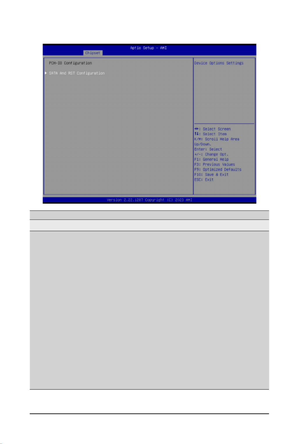
- 75 -
BIOS Setup
2-3-7 PCH Conguration
Parameter Description
PCH-IOConguration
SATAAndRSTConguration/
SATA Controller And RST
Conguration
Press[Enter]tocongureadvanceditems.
SATAConguration
– Enable/Disable SATA controller.
– Options available: Enabled, Disabled. Default setting is .Enabled
SATA Mode Selection
– ConguresonchipSATAtype.
– AHCI Mode: When set to AHCI, the SATA controller enables its AHCI
functionality. Then the RAID function is disabled and cannot be
access the RAID setup utility at boot time.
– RAID Mode: When set to RAID, the SATA controller enables both its
RAID and AHCI functions. You will be allowed to access the RAID
setup utility at boot time.
– Options available: AHCI, RAID. Default setting is .AHCI
RAID Device ID(Note)
– Choose RAID Device ID.
– Options available: Client, Alternate, Server. Default setting is Server.
SATA Port 0/1/2/3/4/5
– ThecategoryidentiesSATAharddrivesthatareinstalledinthe
computer. System will automatically detect HDD type.
(Note) Only appears when HDD sets to Mode.RAID

- 76 -
BIOS Setup
Parameter Description
SATA And RST
Conguration/
SATA Controller And RST
Conguration(continued)
SATA Port 0/1/2/3/4/5
– Enable/Disable Port 0/1/2/3/4/5 device.
– Options available: Enabled, Disabled. Default setting is .Enabled
Hot Plug (for Port 0/1/2/3/4/5)
– Enable/Disable HDD Hot-Plug function.
– Options available: Enabled, Disabled. Default setting is .Enabled
Spin Up Device (for Port 0/1/2/3/4/5)
– On an edge detect from 0 to 1, the PCH starts a COM reset
initialization to the device.
– Options available: Enabled, Disabled. Default setting is .Disabled
(Note) Only appears when HDD sets to Mode.RAID

- 77 -
BIOS Setup
2-3-8 Miscellaneous Conguration
Parameter Description
MiscellaneousConguration
Active Video
Selects the active video type.
Optionsavailable:Auto,OnboardDevice,PCIEDevice,SpecicPCIE
Device. Default setting is .Auto
External SSC - CK440
Enables Spread spectrum - only affects external clock generator.
Options available: SSC Off, SSC = -0.3%, SSC = -0.5%, Hardware.
Default setting is .SSC Off

- 78 -
BIOS Setup
2-3-9 Server ME Conguration
Parameter Description
GeneralMEConguration
Oper. Firmware Version Displaystheoperationalrmwareversion.
ME Firmware Status #1/#2 Displays ME Firmware status information.
Current State Displays ME Firmware current status information.
Error Code Displays ME Firmware status error code.
Recovery Cause Displays ME Firmware recovery cause.

- 79 -
BIOS Setup
2-3-10 Runtime Error Logging Settings
Parameter Description
Runtime Error Logging
System Errors Enable/Disable system error logging function.
Options available: Enable, Disable. Default setting is .Enable
Whea Settings
Press[Enter]tocongureadvanceditems.
WHEA (Windows Hardware Error Architecture) Support
– Enable/Disable WHEA Support.
– Options available: Enable, Disable. Default setting is .Enable
Memory Error Enabling
Press[Enter]tocongureadvanceditems.
Memory Corrected Error
– Enable/Disable Memory Corrected Error.
– Options available: Enable, Disable. Default setting is .Enable
Uncorrected Error disable Memory
– Enable/Disable the Memory that triggers Uncorrected Error.
– Options available: Enable, Disable. Default setting is .Disable
PCIe Error Enabling
Press[Enter]tocongureadvanceditems.
PCIE Error
– Enable/Disable PCIE error.
– Options available: Enable, Disable. Default setting is .Disable

- 80 -
BIOS Setup
Parameter Description
PCIe Error Enabling
(continued)
Uncorrected Error
(Note)
– Enables and escalates Uncorrectable/Recoverable Errors to error pins.
– Options available: Enable, Disable. Default setting is .Enable
Fatal Error Enable(Note)
– Enables and escalates Fatal Errors to error pins.
– Options available: Enable, Disable. Default setting is .Enable
Assert NMI on SERR(Note)
– Enable/Disable BIOS generates a non-maskable interrupt (NMI) and logs
an error when a system error (SERR) occurs.
– Options available: Enabled, Disabled. Default setting is .Enabled
Assert NMI on PERR(Note)
– Enable/Disable BIOS generates a non-maskable interrupt (NMI) and logs
an error when a processor bus parity error (PERR) occurs.
– Options available: Enabled, Disabled. Default setting is .Enabled
(Note) This item appears when is set to . PCIE Error Enable

- 81 -
BIOS Setup
2-3-11 Power Policy
Parameter Description
Power Policy Quick Settings
Selects a Power Policy Quick Setting.
Optionsavailable:Standard,BestPerformance,EnergyEfcient.Default
setting is .Standard
SpeedStep (Pstates)
Conventional Intel SpeedStep Technology switches both voltage and
frequency in tandem between high and low levels in response to processor
load.
Options available: Enable, Disable. Default setting is .Enable
Turbo Mode
When this item is enabled, the processor will automatically ramp up the
clock speed of 1-2 of its processing cores to improve its performance.
When this item is disabled, the processor will not overclock any of its core.
Options available: Enable, Disable. Default setting is .Enable
CPU C6 report
Enable/Disable the BIOS to enable the report from the CPU C6 state (ACPI
C3) to the OS.
Options available: Disable, Enable, Auto. Default setting is .Auto
Enhanced Halt State (C1E)
Enable/Disable the C1E support for lower power consumption. Takes effect
after reboot.
Options available: Enable, Disable. Default setting is .Enable
Package C State
CongurestheC-Statepackagelimit.
Options available: C0/C1 state, C2 state, C6(non Retention) state,
C6(Retention) state, No Limit, Auto. Default setting is .Auto

- 82 -
BIOS Setup
Parameter Description
Enable LP [Global]
Enables Logical processor (Software Method to Enable/Disable Logical
Processor threads).
Options available: ALL LPs, Single LP. Default setting is .ALL LPs
Hardware Prefetcher Options available: Enable, Disable. Default setting is .Enable
AdjacentCachePrefetch Options available: Enable, Disable. Default setting is .Enable
DCU Streamer Prefetcher Options available: Enable, Disable. Default setting is .Enable
Intel® VT for Directed I/O
Enable/Disable the Intel VT for Directed I/O (VT-d) support function by
reporting the I/O device assignment to VMM through DMAR ACPI Tables.
Options available: Enable, Disable. Default setting is .Enable
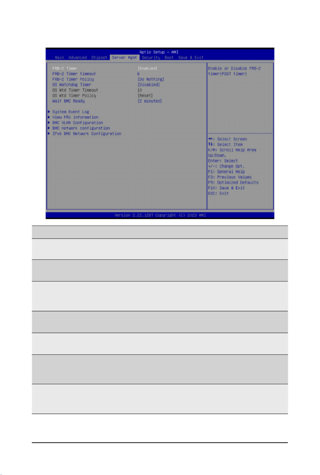
- 83 -
BIOS Setup
2-4 Server Management Menu
Parameter Description
FRB-2 Timer Enable/Disable FRB-2 timer (POST timer).
Options available: Enabled, Disabled. Default setting is .Enabled
FRB-2 Timer(Note1)
timeout
CongurestheFRB2Timertimeout.Thevalueisbetween1to30minutes.
Default setting is .6 minutes
FRB-2 Timer
Policy(Note1)
CongurestheFRB2Timerpolicy.
Options available: Do Nothing, Reset, Power Down, Power Cycle.
Default setting is .Do Nothing
OS Watchdog
Timer
Enable/Disable OS Watchdog Timer function.
Options available: Enabled, Disabled. Default setting is .Disabled
OS Wtd Timer
Timeout(Note2)
ConguresOSWatchdogTimer.Thevalueisbetween1to30minutes.
Default setting is .10 minutes
OS Wtd Timer
Policy(Note2)
CongureOSWatchdogTimerPolicy.
Options available: Reset, Do Nothing, Power Down, Power Cycle.
Default setting is .Reset
Wait BMC Ready
POST wait BMC ready and reboot system.
Options available: Disabled, 2 minutes, 4 minutes, 6 minutes.
Default setting is .2 minutes
(Note1) This item is set to .iscongurablewhen FRB-2 Timer Enabled
(Note2) This item iscongurablewhen OS Watchdog Timer Enabled is set to .

- 84 -
BIOS Setup
Parameter Description
System Event Log Press[Enter]tocongureadvanceditems.
View FRU
Information Press [Enter] to view the FRU information.
BMC VLAN
Conguration Press[Enter]tocongureadvanceditems.
BMC network
Conguration Press[Enter]tocongureadvanceditems.
IPv6 BMC Network
Conguration Press[Enter]tocongureadvanceditems.
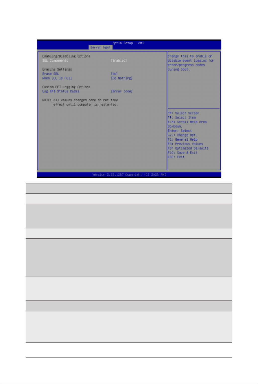
- 85 -
BIOS Setup
2-4-1 System Event Log
Parameter Description
Enabling / Disabling Options
SEL Components
Change this item to enable or disable all features of System Event
Logging during boot.
Options available: Enabled, Disabled. Default setting is .Enabled
Erasing Settings
Erase SEL
Choose options for erasing SEL.
Options available: No,
Yes, On next reset,
Yes, On every reset.
Default setting is .No
When SEL is Full
Choose options for reactions to a full SEL.
Options available: Do Nothing, Erase Immediately, Delete Oldest Record.
Default setting is .Do Nothing
Custom EFI Logging Options
Log EFI Status Codes
Enable/Disable the logging of EFI Status Codes (if not already converted
to legacy).
Options available: Disabled, Both, Error code, Progress code. Default
setting is .Error code

- 86 -
BIOS Setup
2-4-2 View FRU Information
The FRU page is a simple display page for basic system ID information, as well as System product
information.Itemsonthiswindowarenon-congurable.
(Note) The model name will vary depends on the product you purchased

- 87 -
BIOS Setup
2-4-3 BMC VLAN Conguration
Parameter Description
BMCVLANConguration
BMC VLAN ID SelecttocongureBMCVLANID.Thevalidrangeisfrom0to4094.When
set to 0, BMC VLAN ID will be disabled.
BMC VLAN Priority SelecttocongureBMCVLANPriority.Thevalidrangeisfrom0to7.
When BMC VLAN ID is set to 0, BMC VLAN Priority will not be selected.

- 88 -
BIOS Setup
2-4-4 BMC Network Conguration
Parameter Description
BMCnetworkconguration
Select NCSI and Dedicated
LAN
Options available: Do Nothing, Model1(Dedicated), Model2(NCSI),
Mode3(Failover). Default setting is .Do Nothing
Lan Channel 1
CongurationAddresssource
SelectstocongureLANchannelparametersstaticallyordynamically
(DHCP).
Optionsavailable:Unspecied,Static,DynamicBmcDhcp.Defaultsetting
is .DynamicBmcDhcp
Station IP address Displays IP Address information.
Subnet mask
Displays Subnet Mask information.
Please note that the IP address must be in three digitals, for example,
192.168.000.001.
Router IP address Displays the Router IP Address information.
Station MAC address Displays the MAC Address information.
Real-time get BMC network
address
Press [Enter] will set LAN mode and Address source and then get IP,
Subnet, Gateway and MAC address.
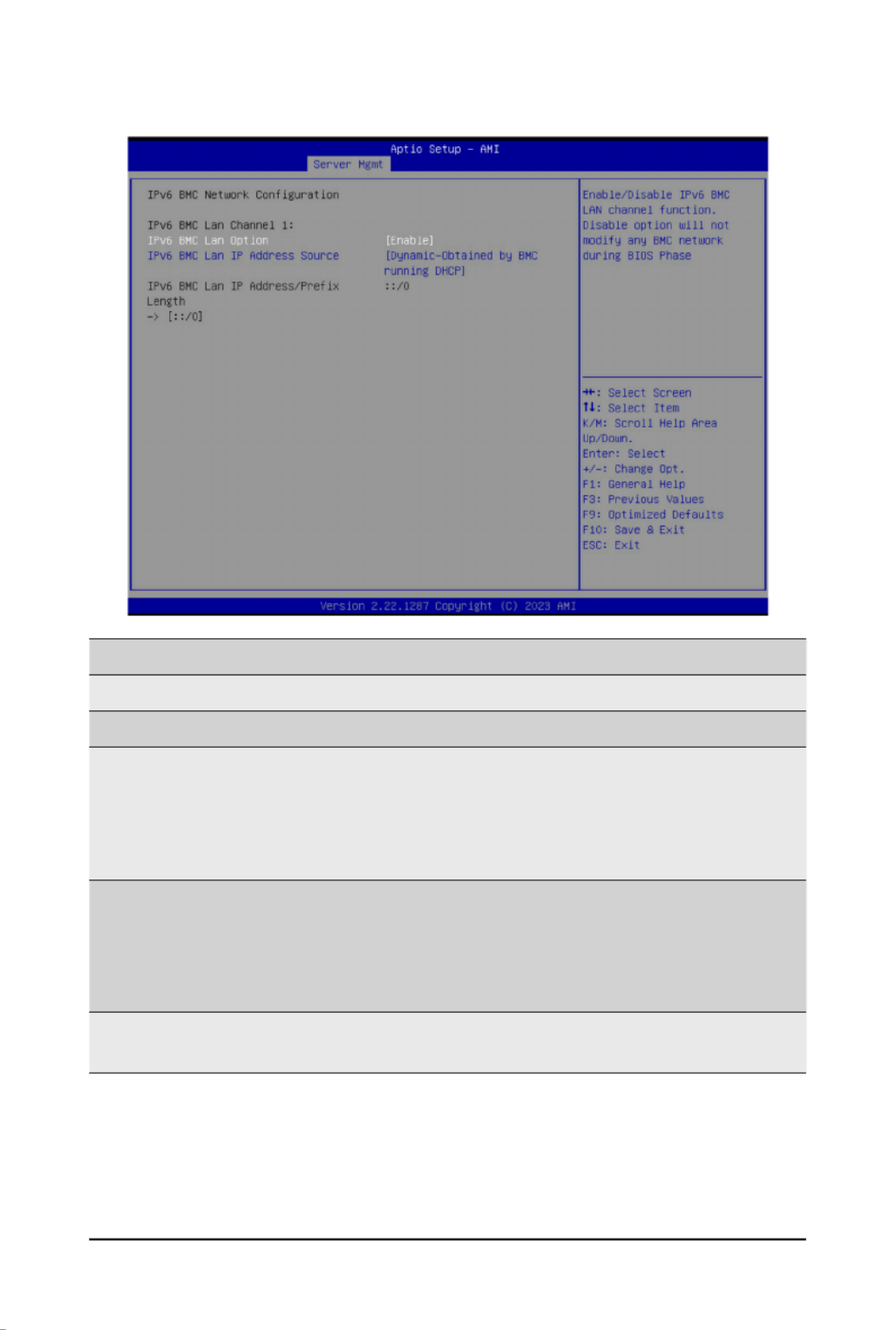
- 89 -
BIOS Setup
2-4-5 IPv6 BMC Network Conguration
Parameter Description
IPv6BMCnetworkconguration
IPv6 BMC Lan Channel 1
IPv6 BMC Lan Option
Enable/Disable IPv6 BMC LAN channel function. When this item is
disabled, the system will not modify any BMC network during BIOS
phase.
Optionsavailable:Unspecied,Disable,Enable.Defaultsettingis
Enable.
IPv6 BMC Lan IP Address
Source
SelectstocongureLANchannelparametersstaticallyordynamically(by
BIOS or BMC).
Optionsavailable:Unspecied,Static,Dynamic-ObtainedbyBMC
running DHCP. Default setting is Dynamic-Obtained by BMC running
DHCP.
IPv6 BMC Lan IP Address/
PrexLength
Check if the IPv6 BMC LAN IP address matches those displayed on the
screen.
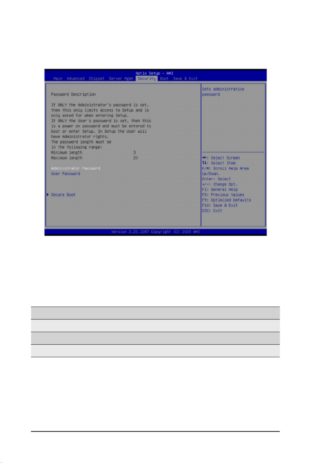
- 90 -
BIOS Setup
2-5 Security Menu
The Security menu allows you to safeguard and protect the system from unauthorized use by setting up
access passwords.
There are two types of passwords that you can set:
• Administrator Password
Entering this password will allow the user to access and change all settings in the Setup Utility.
• User Password
Entering this password will restrict a user’s access to the Setup menus. To enable or disable
thiseld,aAdministratorPasswordmustrstbeset.Ausercanonlyaccessandmodifythe
SystemTime,SystemDate,andSetUserPasswordelds.
Parameter Description
Administrator Password Press[Enter]toconguretheadministratorpassword.
User Password Press[Enter]toconguretheuserpassword.
Secure Boot Press[Enter]tocongureadvanceditems.

- 91 -
BIOS Setup
2-5-1 Secure Boot
The Secure Boot submenu is applicable when your device is installed the Windows® 8 (or above) operating
system.
(Note) Advanced items prompt when this item is set to .Custom
Parameter Description
System Mode Displays if the system is in User mode or Setup mode.
Secure Boot Enable/ Disable the Secure Boot function.
Options available: Enabled, Disabled. Default setting is .Disabled
Secure Boot Mode(Note)
Secure Boot requires all the applications that are running during the
bootingprocesstobepre-signedwithvaliddigitalcerticates.Thisway,
thesystemknowsalllesbeingloadedbeforeWindowsloadstothelogin
screen have not been tampered with.
When set to Standard, it will automatically load the Secure Boot keys
form the BIOS databases.
When set to Custom, you can customize the Secure Boot settings and
manually load its keys from the BIOS database.
Options available: Standard, Custom. Default setting is .Custom
Restore Factory Keys Forces the system to user mode and installs factory default Secure Boot
key database.
Reset To Setup Mode Reset the system to Setup Mode.
Termékspecifikációk
| Márka: | Gigabyte |
| Kategória: | szerver |
| Modell: | MS03-6L0 |
Szüksége van segítségre?
Ha segítségre van szüksége Gigabyte MS03-6L0, tegyen fel kérdést alább, és más felhasználók válaszolnak Önnek
Útmutatók szerver Gigabyte

16 December 2024
11 Október 2024
6 Október 2024
29 Augusztus 2024
29 Augusztus 2024
29 Augusztus 2024
29 Augusztus 2024
29 Augusztus 2024
29 Augusztus 2024
29 Augusztus 2024
Útmutatók szerver
- szerver Sony
- szerver Fujitsu
- szerver Acer
- szerver StarTech.com
- szerver Lenovo
- szerver Toshiba
- szerver HP
- szerver Medion
- szerver Vimar
- szerver Technics
- szerver Rocstor
- szerver Digitus
- szerver TRENDnet
- szerver Dell
- szerver Tripp Lite
- szerver Conceptronic
- szerver Blackmagic Design
- szerver Hikvision
- szerver Netgear
- szerver Asus
- szerver ELAC
- szerver Synology
- szerver Supermicro
- szerver ZyXEL
- szerver Smart-AVI
- szerver Planet
- szerver Ernitec
- szerver Black Box
- szerver MSI
- szerver Cisco
- szerver ATen
- szerver APC
- szerver SEH
- szerver Western Digital
- szerver HGST
- szerver D-Link
- szerver Monacor
- szerver Moxa
- szerver Abus
- szerver Veritas
- szerver Atlona
- szerver Lindy
- szerver Areca
- szerver QNAP
- szerver NEC
- szerver Siig
- szerver Eaton
- szerver Gefen
- szerver Kathrein
- szerver IStarUSA
- szerver Lantronix
- szerver Provision-ISR
- szerver Axis
- szerver NETSCOUT
- szerver Sitecom
- szerver ACTi
- szerver Megasat
- szerver KanexPro
- szerver Kramer
- szerver Allnet
- szerver SilverStone
- szerver Maxdata
- szerver AVerMedia
- szerver Matrox
- szerver Flir
- szerver Buffalo
- szerver GeoVision
- szerver LevelOne
- szerver LaCie
- szerver Valcom
- szerver Asustor
- szerver Intel
- szerver Fantec
- szerver Freecom
- szerver Seagate
- szerver Iomega
- szerver Digi
- szerver Revox
- szerver Luxman
- szerver Ibm
- szerver Sonnet
- szerver TAIDEN
- szerver Advantech
- szerver Extron
- szerver Avocent
- szerver Intellinet
- szerver Teradek
- szerver Silex
- szerver Hanwha
- szerver In Win
- szerver Sun
- szerver MvixUSA
- szerver Dual Bay
- szerver Raidsonic
- szerver EMC
- szerver Infortrend
- szerver Opengear
- szerver G-Technology
- szerver EXSYS
- szerver Chenbro Micom
- szerver Middle Atlantic
- szerver Mr. Signal
- szerver Atlantis Land
- szerver C2G
- szerver Promise Technology
- szerver Mobotix
- szerver Origin Storage
Legújabb útmutatók szerver

9 Április 2025
3 Április 2025

2 Április 2025
29 Március 2025
29 Március 2025
29 Március 2025
24 Március 2025
24 Március 2025

15 Január 2025
15 Január 2025