Használati útmutató Gigabyte GA-Z87M-D3H
Olvassa el alább 📖 a magyar nyelvű használati útmutatót Gigabyte GA-Z87M-D3H (100 oldal) a alaplap kategóriában. Ezt az útmutatót 3 ember találta hasznosnak és 2 felhasználó értékelte átlagosan 4.5 csillagra
Oldal 1/100

GA-Z87M-D3H
GA-H87M-D3H
User's Manual
Rev. 1002
12ME-Z87MD3H-1002R

Motherboard
GA-Z87M-D3H
GA-H87M-D3H
Mar. 29, 2013
Mar. 29, 2013
Motherboard
GA-Z87M-D3H/GA-H87M-D3H

Copyright
© 2013 GIGA-BYTE TECHNOLOGY CO., LTD. All rights reserved.
The trademarks mentioned in this manual are legally registered to their respective owners.
Disclaimer
Information in this manual is protected by copyright laws and is the property of GIGABYTE.
Changes to the specications and features in this manual may be made by GIGABYTE
without prior notice.
No part of this manual may be reproduced, copied, translated, transmitted, or published in any
form or by any means without GIGABYTE's prior written permission.
Documentation Classications
In order to assist in the use of this product, GIGABYTE provides the following types of
documentations:
For quick set-up of the product, read the Quick Installation Guide included with the product.
For detailed product information, carefully read the User's Manual.
For product-related information, check on our website at: http://www.gigabyte.com
Identifying Your Motherboard Revision
The revision number on your motherboard looks like this: "REV: X.X." For example, "REV:
1.0" means the revision of the motherboard is 1.0. Check your motherboard revision before
updating motherboard BIOS, drivers, or when looking for technical information.
Example:

- 4 -
Table of Contents
Box Contents 6 ...................................................................................................................
Optional Items 6 .................................................................................................................
GA-Z87M-D3H/GA-H87M-D3H Motherboard Layout 7 ......................................................
GA-Z87M-D3H/GA-H87M-D3H Motherboard Block Diagram 8 .........................................
Chapter 1 Hardware Installation 9 .....................................................................................
1-1 Installation Precautions 9 ....................................................................................
1-2 ProductSpecications .................................................................................... 10
1-3 Installing the CPU and CPU Cooler 13 ...............................................................
1-3-1 Installing the CPU 13 ...................................................................................................
1-3-2 Installing the CPU Cooler 15 .......................................................................................
1-4 Installing the Memory 16 .....................................................................................
1-4-1 DualChannelMemoryConguration .....................................................................16
1-4-2 Installing a Memory 17 ................................................................................................
1-5 Installing an Expansion Card 18 .........................................................................
1-6 Back Panel Connectors 19 ..................................................................................
1-7 Internal Connectors 21 ........................................................................................
Chapter 2 BIOS Setup 31 ..................................................................................................
2-1 Startup Screen 32 ...............................................................................................
2-2 The Main Menu 33 ..............................................................................................
2-3 M.I.T. .............................................................................................................. 35
2-4 System ........................................................................................................... 45
2-5 BIOS Features 46 ...............................................................................................
2-6 Peripherals ..................................................................................................... 50
2-7 Power Management 54 .......................................................................................
2-8 Save & Exit 56 .....................................................................................................
Chapter3 ConguringSATAHardDrive(s) ...................................................................57
3-1 ConguringSATAControllers ......................................................................... 57
3-2 Installing the SATA RAID/AHCI Driver and Operating System 69 .......................

- 5 -
Chapter 4 Drivers Installation 73 ........................................................................................
4-1 Chipset Drivers 73 ...............................................................................................
4-2 Application Software 74 ......................................................................................
4-3 Information ..................................................................................................... 74
Chapter 5 Unique Features 75 ...........................................................................................
5-1 BIOS Update Utilities 75 .....................................................................................
5-1-1 Updating the BIOS with the Q-Flash Utility 75 .............................................................
5-1-2 Updating the BIOS with the @BIOS Utility 78 .............................................................
5-2 APP Center 79 ....................................................................................................
5-2-1 EasyTune................................................................................................................80
5-2-2 EZ Setup 81 .................................................................................................................
5-2-3 USB Blocker 86 ...........................................................................................................
Chapter 6 Appendix 87 ......................................................................................................
6-1 ConguringAudioInputandOutput ............................................................... 87
6-1-1 Conguring2/4/5.1/7.1-ChannelAudio ...................................................................87
6-1-2 ConguringS/PDIFOut ..........................................................................................89
6-1-3 ConguringMicrophoneRecording ........................................................................90
6-1-4 Using the Sound Recorder 92 .....................................................................................
6-2 Troubleshooting.............................................................................................. 93
6-2-1 Frequently Asked Questions ...................................................................................93
6-2-2 Troubleshooting Procedure 94 ....................................................................................
Regulatory Statements 96 ..............................................................................................
Contact Us 99 ................................................................................................................

- 6 -
Box Contents
5GA-Z87M-D3H or GA-H87M-D3H motherboard
5Motherboard driver disk
5User's Manual
5Quick Installation Guide
5Two SATA 6Gb/s cables
5I/O Shield
Optional Items
2-portUSB2.0bracket(PartNo.12CR1-1UB030-6*R)
eSATAbracket(PartNo.12CF1-3SATPW-4*R)
3.5"FrontPanelwith2USB3.0/2.0ports(PartNo.12CR1-FPX582-2*R)
COMportcable(PartNo.12CF1-1CM001-3*R)
LPTportcable(PartNo.12CF1-1LP001-0*R)
The box contents above are for reference only and the actual items shall depend on the product package you obtain.
The box contents are subject to change without notice.

- 7 -
GA-Z87M-D3H/GA-H87M-D3H Motherboard Layout
MOnly for GA-Z87M-D3H.
NOnly for GA-H87M-D3H.
KB_MS_USB
CPU_FAN
SYS_FAN2
SYS_FAN3
LGA1150
ATX
GA-Z87M-D3H/
GA-H87M-D3H
F_AUDIO
AUDIO
M_BIOS
DDR3_4
DDR3_3
DDR3_2
DDR3_1
BAT
F_PANEL
ATX_12V_2X4
Intel®
Z87 M
Intel®
H87 N
135
0 2 4 F_USB30
R_USB30
CODEC
CLR_CMOS
B_BIOS
VGA_DVI
USB30_LAN
PCIEX16
PCI1
PCI2
PCIEX4
SPDIF_O
F_USB1F_USB2F_USB3LPT
TPM
COM
SYS_FAN1
HDMI
Realtek ®
GbELAN
iTE®
Super I/O
SATA3

- 8 -
D-Sub
DVI-D
HDMI
GA-Z87M-D3H/GA-H87M-D3H Motherboard Block Diagram
Fordetailedproductinformation/limitation(s),referto"1-2ProductSpecications."
PS/2 KB/Mouse
COM
LPT
LPC
Bus
LGA1150
CPU
PCI Express Bus
CPUCLK+/-(100MHz)
PCIe CLK
(100MHz)
1 PCI Express x16
x16
DMI 2.0
FDI
DDR31600/1333MHz
Dual Channel Memory
LAN
RJ45
PCI Express Bus
PCIe CLK
(100MHz) Realtek®
GbELAN
PCIe to
PCI Bridge
1 PCI Express x4
x4 x1
PCI Bus
x1
Dual BIOS
6 USB 3.0/2.0
6 SATA 6Gb/s
8 USB 2.0/1.1
Intel® Z87 M
Intel® H87 N
iTE®
Super I/O
MOnly for GA-Z87M-D3H.
NOnly for GA-H87M-D3H.
Center/Subwoofer Speaker Out
Line Out
MIC
Line In
S/PDIF Out
Side Speaker Out
Rear Speaker Out
CODEC
2 PCI
PCI CLK
(33MHz)

- 9 -
Hardware Installation
Chapter 1 Hardware Installation
1-1 Installation Precautions
The motherboard contains numerous delicate electronic circuits and components which can become
damagedasaresultofelectrostaticdischarge(ESD).Priortoinstallation,carefullyreadtheuser's
manual and follow these procedures:
•Prior to installation, make sure the chassis is suitable for the motherboard.
•Prior to installation, do not remove or break motherboard S/N (Serial Number) sticker or
warranty sticker provided by your dealer. These stickers are required for warranty validation.
•Always remove the AC power by unplugging the power cord from the power outlet before
installing or removing the motherboard or other hardware components.
•Whenconnectinghardwarecomponentstotheinternalconnectorsonthemotherboard,make
sure they are connected tightly and securely.
•Whenhandlingthemotherboard,avoidtouchinganymetalleadsorconnectors.
•It is best to wear an electrostatic discharge (ESD) wrist strap when handling electronic
components such as a motherboard, CPU or memory. If you do not have an ESD wrist strap,
keepyourhandsdryandrsttouchametalobjecttoeliminatestaticelectricity.
•Prior to installing the motherboard, please have it on top of an antistatic pad or within an
electrostatic shielding container.
•Before unplugging the power supply cable from the motherboard, make sure the power supply
has been turned off.
•Before turning on the power, make sure the power supply voltage has been set according to
the local voltage standard.
•Before using the product, please verify that all cables and power connectors of your hardware
components are connected.
•To prevent damage to the motherboard, do not allow screws to come in contact with the
motherboard circuit or its components.
•Make sure there are no leftover screws or metal components placed on the motherboard or
within the computer casing.
•Do not place the computer system on an uneven surface.
•Do not place the computer system in a high-temperature environment.
•Turning on the computer power during the installation process can lead to damage to system
components as well as physical harm to the user.
•If you are uncertain about any installation steps or have a problem related to the use of the
product,pleaseconsultacertiedcomputertechnician.

Hardware Installation
- 10 -
1-2 ProductSpecications
CPU Support for Intel® Core™ i7 processors/Intel® Core™ i5 processors/
Intel® Core™ i3 processors/Intel® Pentium® processors/Intel® Celeron® processors
in the LGA1150 package
(GotoGIGABYTE'swebsiteforthelatestCPUsupportlist.)
L3 cache varies with CPU
Chipset Intel® Z87 /H87 Express ChipsetM N
Memory 4x1.5VDDR3DIMMsocketssupportingupto32GBofsystemmemory
* DuetoaWindows32-bitoperatingsystemlimitation,whenmorethan4GBofphysical
memoryisinstalled,theactualmemorysizedisplayedwillbelessthanthesizeof
the physical memory installed.
Dual channel memory architecture
SupportforDDR31600/1333MHzmemorymodules
Support for non-ECC memory modules
SupportforExtremeMemoryProle(XMP)memorymodules
(GotoGIGABYTE'swebsiteforthelatestsupportedmemoryspeedsandmemory
modules.)
Onboard
Graphics
Integrated Graphics Processor:
- 1 x D-Sub port, supporting a maximum resolution of 1920x1200
- 1xDVI-Dport,supportingamaximumresolutionof1920x1200
* TheDVI-DportdoesnotsupportD-Subconnectionbyadapter.
- 1 x HDMI ports, supporting a maximum resolution of 4096x2160
* SupportforHDMI1.4aversion.
- Maximum shared memory of 1 GB
Audio Realtek® ALC892 codec
HighDenitionAudio
2/4/5.1/7.1-channel
* Tocongure7.1-channelaudio,youhavetouseanHDfrontpanelaudiomodule
and enable the multi-channel audio feature through the audio driver.
Support for S/PDIF Out
LAN Realtek®GbELANchip(10/100/1000Mbit)
Expansion Slots 1xPCIExpressx16slot,runningatx16(PCIEX16)
* Foroptimumperformance,ifonlyonePCIExpressgraphicscardistobeinstalled,
besuretoinstallitinthePCIEX16slot.
(ThePCIEX16slotconformstoPCIExpress3.0standard.)
1xPCIExpressx16slot,runningatx4(PCIEX4)
(ThePCIEX4slotconformstoPCIExpress2.0standard.)
2 x PCI slots
Multi-Graphics
Technology Support for AMD CrossFire™ technology
MOnly for GA-Z87M-D3H.
NOnly for GA-H87M-D3H.
- 11 -
Hardware Installation
Storage Interface Chipset:
- 6 x SATA 6Gb/s connectors supporting up to 6 SATA 6Gb/s devices
- Support for RAID 0, RAID 1, RAID 5, and RAID 10
USB Chipset:
- Upto8USB2.0/1.1ports(2portsonthebackpanel,6portsavailablethrough
theinternalUSBheaders)
- Upto6USB3.0/2.0ports(4portsonthebackpanel,2portsavailablethrough
theinternalUSBheader)
Internal
Connectors
1x24-pinATXmainpowerconnector
1x8-pinATX12Vpowerconnector
6 x SATA 6Gb/s connectors
1 x CPU fan header
3 x system fan headers
1 x front panel header
1 x front panel audio header
1 x S/PDIF Out header
1 x USB 3.0/2.0 header
3 x USB 2.0/1.1 headers
1 x serial port header
1 x parallel port header
1xTrustedPlatformModule(TPM)header
1 x Clear CMOS jumper
Back Panel
Connectors
1 x PS/2 keyboard/mouse port
1 x D-Sub port
1xDVI-Dport
1 x HDMI port
4 x USB 3.0/2.0 ports
2 x USB 2.0/1.1 ports
1 x RJ-45 port
6xaudiojacks(Center/SubwooferSpeakerOut/RearSpeakerOut/SideSpeaker
Out/LineIn/LineOut/Microphone)
I/O Controller iTE® I/O Controller Chip
Hardware
Monitor
System voltage detection
CPU/System temperature detection
CPU/System fan speed detection
CPU/System overheating warning
CPU/System fan fail warning
CPU/System fan speed control
* Whetherthefanspeedcontrolfunctionissupportedwilldependonthecooleryou
install.

Hardware Installation
- 12 -
BIOS 2x64Mbitash
Use of licensed AMI EFI BIOS
Support for DualBIOS™
PnP 1.0a, DMI 2.0, SM BIOS 2.6, ACPI 2.0a
Unique Features Support for Q-Flash
SupportforXpressInstall
Support for APP Center
* AvailableapplicationsinAPPCentermaydifferbymotherboardmodel.Supported
functionsofeachapplicationmayalsodifferdependingonmotherboardspecications.
- @BIOS
- EasyTune
- EZ Setup
- USB Blocker
SupportforON/OFFCharge
Bundled
Software
NortonInternetSecurity(OEMversion)
Intel® Rapid Start Technology
Intel® Smart Connect Technology
Intel® Smart Response Technology
Intel® Small Business Advantage N
Operating
System SupportforWindows8/7
Form Factor MicroATXFormFactor;24.4cmx22.5cm
* GIGABYTEreservestherighttomakeanychangestotheproductspecicationsandproduct-relatedinformationwithout
prior notice.
* Pleasevisitthe pageonGIGABYTE'swebsitetocheckthesupportedoperatingsystem(s)Support & Downloads\Utility
for the software listed in the "Unique Features" and "Bundled Software" columns.
NOnly for GA-H87M-D3H.

- 13 -
Hardware Installation
1-3 Installing the CPU and CPU Cooler
1-3-1 Installing the CPU
A. Locate the alignment keys on the motherboard CPU socket and the notches on the CPU.
Read the following guidelines before you begin to install the CPU:
•Make sure that the motherboard supports the CPU.
(GotoGIGABYTE'swebsiteforthelatestCPUsupportlist.)
•Always turn off the computer and unplug the power cord from the power outlet before installing the
CPU to prevent hardware damage.
•LocatethepinoneoftheCPU.TheCPUcannotbeinsertediforientedincorrectly.(Oryoumay
locatethenotchesonbothsidesoftheCPUandalignmentkeysontheCPUsocket.)
•Apply an even and thin layer of thermal grease on the surface of the CPU.
•Do not turn on the computer if the CPU cooler is not installed, otherwise overheating and damage
of the CPU may occur.
•SettheCPUhostfrequencyinaccordancewiththeCPUspecications.Itisnotrecommended
thatthesystembusfrequencybesetbeyondhardwarespecicationssinceitdoesnotmeetthe
standard requirements for the peripherals. If you wish to set the frequency beyond the standard
specications,pleasedosoaccordingtoyourhardwarespecicationsincludingtheCPU,graphics
card, memory, hard drive, etc.
Notch
Alignment KeyAlignment Key
Notch
LGA1150 CPU
LGA1150 CPU Socket
Pin One Corner of the CPU Socket
Triangle Pin One Marking on the CPU

Hardware Installation
- 14 -
B. Follow the steps below to correctly install the CPU into the motherboard CPU socket.
Step 1:
Gently press the CPU socket lever handle down
andawayfromthesocketwithyournger.Then
completely lift the CPU socket lever and the metal
load plate/plastic cover will be lifted as well.
Step 2:
HoldtheCPUwithyourthumbandindexngers.
AligntheCPUpinonemarking(triangle)withthe
pinonecorneroftheCPUsocket(oryoumayalign
theCPUnotcheswiththesocketalignmentkeys)
and gently insert the CPU into position.
Step 4:
Finally, secure the lever under its retention tab to
complete the installation of the CPU.
NOTE:
Hold the CPU socket lever by the handle, not the lever base portion.
•Before installing the CPU, make sure to turn off the computer and unplug the power cord from
the power outlet to prevent damage to the CPU.
•To protect the socket contacts, do not remove the protective plastic cover unless the CPU is
inserted into the CPU socket. Save the cover properly and replace it if the CPU is removed.
Step 3:
Once the CPU is properly inserted, carefully
replacetheloadplate.Whenreplacingtheload
plate, make sure the front end of the load plate
is under the shoulder screw. Then press the CPU
socket lever. The protective plastic cover may
pop off from the load plate during the process of
engagingthelever.Removethecover.(Savethe
cover properly and always replace it when the
CPUisnotinstalled.)

- 15 -
Hardware Installation
1-3-2 Installing the CPU Cooler
FollowthestepsbelowtocorrectlyinstalltheCPUcooleronthemotherboard.(Thefollowingprocedureuses
Intel®boxedcoolerastheexamplecooler.)
Use extreme care when removing the CPU cooler because the thermal grease/tape between the CPU
cooler and CPU may adhere to the CPU. Inadequately removing the CPU cooler may damage the CPU.
Step 1:
Apply an even and thin layer of thermal grease on
the surface of the installed CPU.
Male
Push Pin
Female
Push Pin
The Top
of Female
Push Pin
Direction of
the Arrow Sign
on the Male
Push Pin
Step 2:
Before installing the cooler, note the direction of the
arrow sign onthemalepushpin.(Turningthe
push pin along the direction of arrow is to remove
thecooler,onthecontrary,istoinstall.)
Step 3:
Place the cooler atop the CPU, aligning the
four push pins through the pin holes on the
motherboard. Push down on the push pins
diagonally.
Step 4:
You should hear a "click" when pushing down each
push pin. Check that the Male and Female push
pins are joined closely.
(RefertoyourCPUcoolerinstallationmanualfor
instructionsoninstallingthecooler.)
Step 5:
After the installation, check the back of the
motherboard. If the push pin is inserted as the
picture above shows, the installation is complete.
Step 6:
Finally, attach the power connector of the CPU
coolertotheCPUfanheader(CPU_FAN)onthe
motherboard.
Hardware Installation
- 16 -
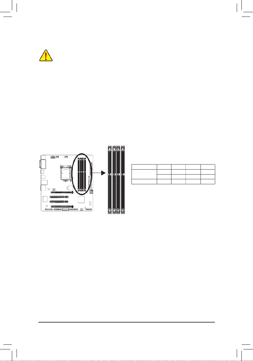
1-4 Installing the Memory
DDR3_4
DDR3_2
DDR3_3
DDR3_1
Due to CPU limitations, read the following guidelines before installing the memory in Dual Channel mode.
1. Dual Channel mode cannot be enabled if only one DDR3 memory module is installed.
2. WhenenablingDualChannelmodewithtwoorfourmemorymodules,itisrecommendedthatmemory
of the same capacity, brand, speed, and chips be used. For optimum performance, when enabling
Dual Channel mode with two memory modules, we recommend that you install them in the DDR3_1
and DDR3_2 sockets.
(SS=Single-Sided,DS=Double-Sided,"--"=NoMemory)
DualChannelMemoryCongurationsTable
DDR3_4 DDR3_2 DDR3_3 DDR3_1
Two Modules - - DS/SS - - DS/SS
DS/SS - - DS/SS - -
Four Modules DS/SS DS/SS DS/SS DS/SS
Read the following guidelines before you begin to install the memory:
•Make sure that the motherboard supports the memory. It is recommended that memory of the same
capacity, brand, speed, and chips be used.
(GotoGIGABYTE'swebsiteforthelatestsupportedmemoryspeedsandmemorymodules.)
•Always turn off the computer and unplug the power cord from the power outlet before installing the
memory to prevent hardware damage.
•Memory modules have a foolproof design. A memory module can be installed in only one direction.
If you are unable to insert the memory, switch the direction.
1-4-1 DualChannelMemoryConguration
This motherboard provides four DDR3 memory sockets and supports Dual Channel Technology. After the
memoryisinstalled,theBIOSwillautomaticallydetectthespecicationsandcapacityofthememory.Enabling
Dual Channel memory mode will double the original memory bandwidth.
The four DDR3 memory sockets are divided into two channels and each channel has two memory sockets as
following:
Channel A: DDR3_1, DDR3_3
Channel B: DDR3_2, DDR3_4

- 17 -
Hardware Installation
1-4-2 Installing a Memory
Before installing a memory module, make sure to turn off the computer and unplug the power
cord from the power outlet to prevent damage to the memory module. DDR3 and DDR2 DIMMs
are not compatible to each other or DDR DIMMs. Be sure to install DDR3 DIMMs on this
motherboard.
Notch
DDR3 DIMM
ADDR3memorymodulehasanotch,soitcanonlytinonedirection.Followthestepsbelowtocorrectlyinstall
your memory modules in the memory sockets.
Step 1:
Notetheorientationofthememorymodule.Spreadtheretainingclips
at both ends of the memory socket. Place the memory module on the
socket.Asindicatedinthepictureontheleft,placeyourngerson
the top edge of the memory, push down on the memory and insert it
vertically into the memory socket.
Step 2:
The clips at both ends of the socket will snap into place when the
memory module is securely inserted.

Hardware Installation
- 18 -
1-5 Installing an Expansion Card
Follow the steps below to correctly install your expansion card in the expansion slot.
1. Locate an expansion slot that supports your card. Remove the metal slot cover from the chassis back panel.
2. Align the card with the slot, and press down on the card until it is fully seated in the slot.
3. Make sure the metal contacts on the card are completely inserted into the slot.
4. Secure the card's metal bracket to the chassis back panel with a screw.
5. Afterinstallingallexpansioncards,replacethechassiscover(s).
6. Turn on your computer. If necessary, go to BIOS Setup to make any required BIOS changes for your
expansioncard(s).
7. Install the driver provided with the expansion card in your operating system.
Example: Installing and Removing a PCI Express Graphics Card:
•Installing a Graphics Card:
Gently push down on the top edge of the card until
it is fully inserted into the PCI Express slot. Make
sure the card is securely seated in the slot and
does not rock.
PCI Slot
PCI Express x16 Slot
Read the following guidelines before you begin to install an expansion card:
•Make sure the motherboard supports the expansion card. Carefully read the manual that came
with your expansion card.
•Always turn off the computer and unplug the power cord from the power outlet before installing an
expansion card to prevent hardware damage.
•Removing the Card:
Gently push back on the lever on the slot and then lift the card straight out from
the slot.

- 19 -
Hardware Installation
1-6 Back Panel Connectors
USB 2.0/1.1 Port
The USB portsupports theUSB 2.0/1.1specication.Usethis portfor USBdevicessuchasa USB
keyboard/mouse,USBprinter,USBashdriveandetc.
PS/2 Keyboard/Mouse Port
Use this port to connect a PS/2 mouse or keyboard.
D-Sub Port
The D-Sub port supports a 15-pin D-Sub connector and supports a maximum resolution of 1920x1200
(theactualresolutionssupporteddependonthemonitorbeingused).Connectamonitorthatsupports
D-Sub connection to this port.
DVI-D Port (Note)
TheDVI-DportconformstotheDVI-Dspecicationandsupportsamaximumresolutionof1920x1200
(theactualresolutionssupporteddependonthemonitorbeingused).Connectamonitorthatsupports
DVI-Dconnectiontothisport.
HDMI Port
The HDMI port is HDCP compliant and supports Dolby True HD and DTS HD
MasterAudioformats.Italsosupportsupto192KHz/24bit8-channelLPCMaudio
output. You can use this port to connect your HDMI-supported monitor. The maximum supported resolution
is 4096x2160, but the actual resolutions supported are dependent on the monitor being used.
(Note) TheDVI-DportdoesnotsupportD-Subconnectionbyadapter.
After installing the HDMI device, make sure to set the default sound playback device to HDMI.
(Theitemnamemaydifferdependingonyouroperatingsystem.Thescreenshotbelowisfrom
Windows8.)
InWindows8,selectAllapps>ControlPanel>Hardware
andSound>Sound>Playback,setIntel(R)DisplayAudio
to the default playback device.
Triple-DisplayCongurationsfortheOnboardGraphics:
Triple-displaycongurationsaresupportedafteryouinstallmotherboarddriversinOS.Onlydual-display
congurationsaresupportedduringtheBIOSSetuporPOSTprocess.

Hardware Installation
- 20 -
Theaudiojackscanbereconguredtoperformdifferentfunctionsviatheaudiosoftware(supported
functionsforeachjackmayvarybasedonhardwarespecication).OnlymicrophonesstillMUST
be connected to the default Mic in jack. Refer to the instructions on setting up a 2/4/5.1/7.1-channel
audiocongurationinChapter6,"Conguring2/4/5.1/7.1-ChannelAudio."
Center/Subwoofer Speaker Out Jack (Orange)
Usethisaudiojacktoconnectcenter/subwooferspeakersina5.1/7.1-channelaudioconguration.
Rear Speaker Out Jack (Black)
Thisjackcanbeusedtoconnectfrontspeakersina4/5.1/7.1-channelaudioconguration.
Side Speaker Out Jack (Gray)
Usethisaudiojacktoconnectsidespeakersina7.1-channelaudioconguration.
Line In Jack (Blue)
The default line in jack. Use this audio jack for line in devices such as an optical drive, walkman, etc.
Line Out Jack (Green)
The default line out jack. Use this audio jack for a headphone or 2-channel speaker. This jack can be used
toconnectfrontspeakersina4/5.1/7.1-channelaudioconguration.
Mic In Jack (Pink)
The default Mic in jack. Microphones must be connected to this jack.
Activity LED
Connection/
Speed LED
LANPort
Activity LED:Connection/Speed LED:
State Description
Orange 1 Gbps data rate
Green 100 Mbps data rate
Off 10 Mbps data rate
State Description
Blinking Data transmission or receiving is occurring
Off Nodatatransmissionorreceivingisoccurring
USB 3.0/2.0 Port
TheUSB3.0portsupportstheUSB3.0specicationandiscompatibletotheUSB2.0/1.1specication.
Use this port for USB devices Use this port for USB devices such as a USB keyboard/mouse, USB printer,
USBashdriveandetc.
RJ-45 LAN Port
TheGigabitEthernet LANportprovidesInternet connectionat upto1Gbpsdata rate.The following
describesthestatesoftheLANportLEDs.
•Whenremovingthecableconnectedtoabackpanelconnector,rstremovethecablefromyour
device and then remove it from the motherboard.
•Whenremovingthecable,pullitstraightoutfromtheconnector.Donotrockitsidetosidetoprevent
an electrical short inside the cable connector.

- 21 -
Hardware Installation
1-7 Internal Connectors
Read the following guidelines before connecting external devices:
•First make sure your devices are compliant with the connectors you wish to connect.
•Before installing the devices, be sure to turn off the devices and your computer. Unplug the power
cord from the power outlet to prevent damage to the devices.
•After installing the device and before turning on the computer, make sure the device cable has
been securely attached to the connector on the motherboard.
1) ATX_12V_2X4
2) ATX
3) CPU_FAN
4) CPU_FAN/SYS_FAN2/SYS_FAN3
5) BAT
6) SATA3 0/1/2/3/4/5
7) F_AUDIO
8) F_PANEL
9) SPDIF_O
10) F_USB30
11) F_USB1/2/3
12) COM
13) LPT
14) TPM
15) CLR_CMOS
1 4 3
10
2
6
15
7 11
9
5
4
6
13 1412 84

Hardware Installation
- 22 -
131
2412
ATX
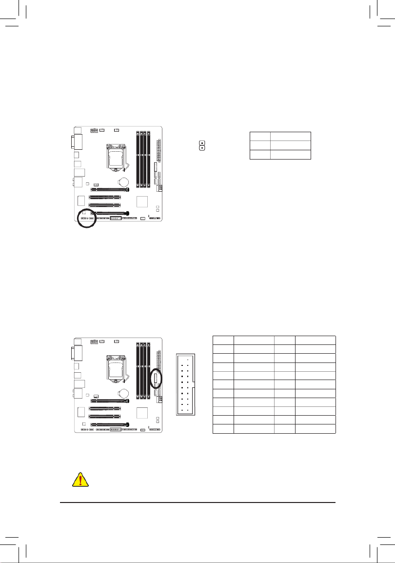
1/2) ATX_12V_2X4/ATX (2x4 12V Power Connector and 2x12 Main Power Connector)
Withtheuseofthepowerconnector,thepowersupplycansupplyenoughstablepowertoallthecomponents
onthemotherboard.Beforeconnectingthepowerconnector,rstmakesurethepowersupplyisturned
off and all devices are properly installed. The power connector possesses a foolproof design. Connect the
power supply cable to the power connector in the correct orientation.
The12VpowerconnectormainlysuppliespowertotheCPU.Ifthe12Vpowerconnectorisnotconnected,
the computer will not start.
To meet expansion requirements, it is recommended that a power supply that can withstand high
powerconsumptionbeused(500Worgreater).Ifapowersupplyisusedthatdoesnotprovidethe
required power, the result can lead to an unstable or unbootable system.
ATX:
PinNo. Denition PinNo. Denition
1 133.3V 3.3V
2 143.3V -12V
3 15GND GND
4 16+5V PS_ON(softOn/Off)
5 17GND GND
6 18+5V GND
7 19GND GND
8 Power Good 20 -5V
9 215VSB(standby+5V) +5V
10 22+12V +5V
11 +12V(Onlyfor2x12-pin
ATX)
23 +5V(Onlyfor2x12-pinATX)
12 3.3V(Onlyfor2x12-pin
ATX)
24 GND(Onlyfor2x12-pin
ATX)
ATX_12V_2X4
41
85
ATX_12V_2X4:
PinNo. Denition
1GND(Onlyfor2x4-pin12V)
2GND(Onlyfor2x4-pin12V)
3GND
4GND
5+12V(Onlyfor2x4-pin12V)
6+12V(Onlyfor2x4-pin12V)
7+12V
8+12V
- 23 -
Hardware Installation
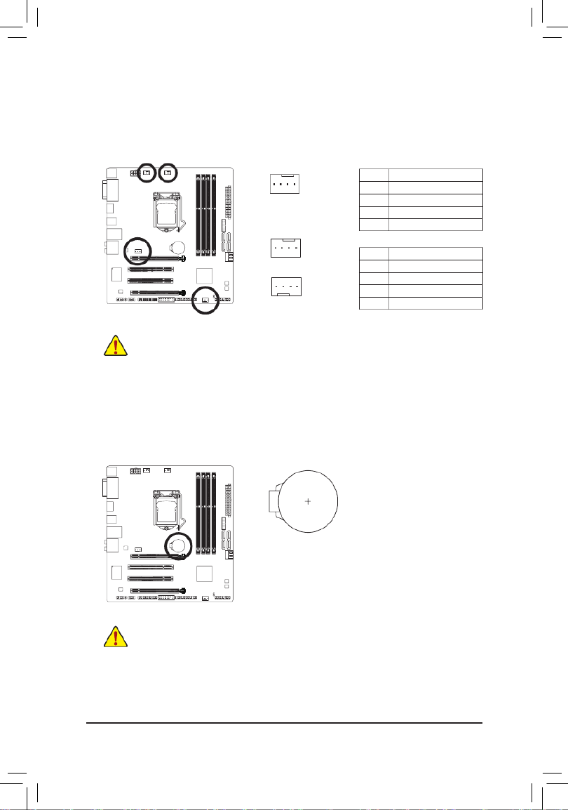
3/4) CPU_FAN/SYS_FAN1/SYS_FAN2/SYS_FAN3 (Fan Headers)
All fan headers on this motherboard are 4-pin. Most fan headers possess a foolproof insertion design.
Whenconnectingafancable,besuretoconnectitinthecorrectorientation(theblackconnectorwireis
thegroundwire).Thespeedcontrolfunctionrequirestheuseofafanwithfanspeedcontroldesign.For
optimum heat dissipation, it is recommended that a system fan be installed inside the chassis.
•Be sure to connect fan cables to the fan headers to prevent your CPU and system from
overheating. Overheating may result in damage to the CPU or the system may hang.
•Thesefanheadersarenotcongurationjumperblocks.Donotplaceajumpercapontheheaders.
5) BAT (Battery)
Thebatteryprovidespowertokeepthevalues(suchasBIOScongurations,date,andtimeinformation)
in the CMOS when the computer is turned off. Replace the battery when the battery voltage drops to a low
level, or the CMOS values may not be accurate or may be lost.
You may clear the CMOS values by removing the battery:
1. Turn off your computer and unplug the power cord.
2. Gently remove the battery from the battery holder and wait for one minute.
(Oruseametalobjectlikeascrewdrivertotouchthepositiveandnegative
terminalsofthebatteryholder,makingthemshortfor5seconds.)
3. Replace the battery.
4. Plug in the power cord and restart your computer.
•Always turn off your computer and unplug the power cord before replacing the battery.
•Replace the battery with an equivalent one. Danger of explosion if the battery is replaced with
an incorrect model.
•Contact the place of purchase or local dealer if you are not able to replace the battery by yourself
or uncertain about the battery model.
•Wheninstallingthebattery,notetheorientationofthepositiveside(+)andthenegativeside(-)
ofthebattery(thepositivesideshouldfaceup).
•Used batteries must be handled in accordance with local environmental regulations.
CPU_FAN:
PinNo. Denition
1GND
2+12V
3 Sense
4 Speed Control
SYS_FAN1/SYS_FAN2/SYS_FAN3:
PinNo. Denition
1GND
2+12V/SpeedControl
3 Sense
4VCC
SYS_FAN1
CPU_FAN
1
1
SYS_FAN2/SYS_FAN3
1

Hardware Installation
- 24 -
•ARAID0orRAID1congurationrequiresatleasttwoharddrives.Ifmorethantwoharddrivesareto
be used, the total number of hard drives must be an even number.
•ARAID5congurationrequiresatleastthreeharddrives.(Thetotalnumberofharddrivesdoesnot
havetobeanevennumber.)
•ARAID10congurationrequiresfourharddrives.
6) SATA3 0/1/2/3/4/5 (SATA 6Gb/s Connectors, Controlled by Intel® Z87 /H87 Chipset)M N
The SATA connectors conform to SATA 6Gb/s standard and are compatible with SATA 3Gb/s and SATA
1.5Gb/s standard. Each SATA connector supports a single SATA device. The Intel® Z87 Chipset M N/H87
supportsRAID0,RAID1,RAID5,andRAID10.RefertoChapter3,"ConguringSATAHardDrive(s),"
forinstructionsonconguringaRAIDarray.
PinNo. Denition
1GND
2TXP
3TXN
4GND
5RXN
6RXP
7GND
7 7
1 1
SATA3
5 4
3 2
7) F_AUDIO (Front Panel Audio Header)
ThefrontpanelaudioheadersupportsIntelHighDenitionaudio(HD)andAC'97audio.Youmayconnect
your chassis front panel audio module to this header. Make sure the wire assignments of the module
connector match the pin assignments of the motherboard header. Incorrect connection between the module
connector and the motherboard header will make the device unable to work or even damage it.
For HD Front Panel Audio: For AC'97 Front Panel Audio:
•The front panel audio header supports HD audio by default. If your chassis provides an AC'97 front panel
audio module, refer to the instructions on how to activate AC'97 functionality via the audio software in
Chapter6,"Conguring2/4/5.1/7.1-ChannelAudio."
•Audio signals will be present on both of the front and back panel audio connections simultaneously. If you
wanttomutethebackpanelaudio(onlysupportedwhenusinganHDfrontpanelaudiomodule),referto
Chapter6,"Conguring2/4/5.1/7.1-ChannelAudio."
•Some chassis provide a front panel audio module that has separated connectors on each wire instead
of a single plug. For information about connecting the front panel audio module that has different wire
assignments, please contact the chassis manufacturer.
PinNo. Denition
1 MIC2_L
2GND
3 MIC2_R
4 -ACZ_DET
5LINE2_R
6GND
7 FAUDIO_JD
8NoPin
9LINE2_L
10 GND
PinNo. Denition
1 MIC
2GND
3 MIC Power
4NC
5LineOut(R)
6NC
7NC
8NoPin
9LineOut(L)
10 NC
1
2
9
10
MOnly for GA-Z87M-D3H.
NOnly for GA-H87M-D3H.
SATA3
1
0
17
17

- 25 -
Hardware Installation
The front panel design may differ by chassis. A front panel module mainly consists of power switch,
resetswitch,powerLED,harddriveactivityLED,speakerandetc.Whenconnectingyourchassis
front panel module to this header, make sure the wire assignments and the pin assignments are
matched correctly.
System Status LED
S0 On
S3/S4/S5 Off
8) F_PANEL (Front Panel Header)
Connect the power switch, reset switch, speaker, chassis intrusion switch/sensor and system status indicator
onthechassistothisheaderaccordingtothepinassignmentsbelow.Notethepositiveandnegativepins
before connecting the cables.
•PW (PowerSwitch):
Connectstothepowerswitchonthechassisfrontpanel.Youmaycongurethewaytoturnoffyour
systemusingthe powerswitch (refer toChapter 2,"BIOSSetup," "Power Management,"for more
information).
•Speaker (Speaker):
Connects to the speaker on the chassis front panel. The system reports system startup status by issuing
a beep code. One single short beep will be heard if no problem is detected at system startup.
•HD (HardDriveActivityLED):
Connects to the hard drive activity LED on the chassis front panel. The LED is on when the hard drive
is reading or writing data.
•RES (ResetSwitch):
Connects to the reset switch on the chassis front panel. Press the reset switch to restart the computer
ifthecomputerfreezesandfailstoperformanormalrestart.
•CI (ChassisIntrusionHeader):
Connects to the chassis intrusion switch/sensor on the chassis that can detect if the chassis cover has
been removed. This function requires a chassis with a chassis intrusion switch/sensor.
•PLED/PWR_LED (PowerLED):
Connects to the power status indicator on the chassis front panel. The LED
is on when the system is operating. The LED is off when the system is in S3/
S4sleepstateorpoweredoff(S5).
PLED-
PW-
SPEAK+
SPEAK-
PLED+
PW+
1
2
19
20
Power LED Power Switch Speaker
Power LED
CI- CI+
PWR_LED+
HD-
RES+
HD+
RES-
Hard Drive
Activity LED
Reset
Switch Chassis Intrusion
Header
PWR_LED-
PWR_LED-
Hardware Installation
- 26 -
1
9) SPDIF_O (S/PDIF Out Header)
ThisheadersupportsdigitalS/PDIFOutandconnectsaS/PDIFdigitalaudiocable(providedbyexpansion
cards)fordigitalaudiooutputfromyourmotherboardtocertainexpansioncardslikegraphicscardsand
sound cards. For example, some graphics cards may require you to use a S/PDIF digital audio cable for
digital audio output from your motherboard to your graphics card if you wish to connect an HDMI display
to the graphics card and have digital audio output from the HDMI display at the same time. For information
about connecting the S/PDIF digital audio cable, carefully read the manual for your expansion card.
PinNo. Denition
1 SPDIFO
2GND
PinNo. Denition PinNo. Denition
1 D2+VBUS 11
2 12 D2-SSRX1-
3 13SSRX1+ GND
4 14GND SSTX2+
5 15SSTX1- SSTX2-
6 16SSTX1+ GND
7 17GND SSRX2+
8 D1- 18 SSRX2-
9 D1+ 19 VBUS
10 20NC NoPin
10) F_USB30 (USB 3.0/2.0 Header)
Theheader conformstoUSB3.0/2.0specicationandcanprovidetwoUSBports.For purchasingthe
optional 3.5" front panel that provides two USB 3.0/2.0 ports, please contact the local dealer.
10
20 1
11
Prior to installing the USB bracket, be sure to turn off your computer and unplug the power cord
from the power outlet to prevent damage to the USB bracket.

- 27 -
Hardware Installation
11) F_USB1/2/3 (USB 2.0/1.1 Headers)
TheheadersconformtoUSB2.0/1.1specication.EachUSBheadercanprovidetwoUSBportsviaan
optional USB bracket. For purchasing the optional USB bracket, please contact the local dealer.
PinNo. Denition
1Power(5V)
2Power(5V)
3USBDX-
4 USB DY-
5USBDX+
6 USB DY+
7GND
8GND
9NoPin
10 NC
•DonotplugtheIEEE1394bracket(2x5-pin)cableintotheUSB2.0/1.1header.
•Prior to installing the USB bracket, be sure to turn off your computer and unplug the power cord
from the power outlet to prevent damage to the USB bracket.
10
9
2
1
PinNo. Denition
1NDCD-
2NSIN
3NSOUT
4NDTR-
5GND
6NDSR-
7NRTS-
8NCTS-
9NRI-
10 NoPin
12) COM (Serial Port Header)
The COM header can provide one serial port via an optional COM port cable. For purchasing the optional
COM port cable, please contact the local dealer.
10
9
2
1

Hardware Installation
- 28 -
13) LPT (Parallel Port Header)
The LPT header can provide one parallel port via an optional LPT port cable. For purchasing the optional
LPT port cable, please contact the local dealer.
26
25
2
1
PinNo. Denition PinNo. Denition
1 STB- 14 GND
2 AFD- 15 PD6
3 PD0 16 GND
4 ERR- 17 PD7
5 PD1 18 GND
6INIT- 19 ACK-
7 PD2 20 GND
8 21 BUSYSLIN-
9 PD3 22 GND
10 23 PEGND
11 PD4 24 NoPin
12 25 SLCTGND
13 PD5 26 GND
14) TPM (Trusted Platform Module Header)
YoumayconnectaTPM(TrustedPlatformModule)tothisheader.
20
19
2
1
PinNo. Denition PinNo. Denition
1 LCLK LAD011
2 12GND GND
3 LFRAME 13 NC
4 14 IDNoPin
5 LRESET 15 SB3V
6 16 SERIRQNC
7 LAD3 17 GND
8 LAD2 18 NC
9 19VCC3 NC
10 LAD1 20 SUSCLK
- 29 -
Hardware Installation
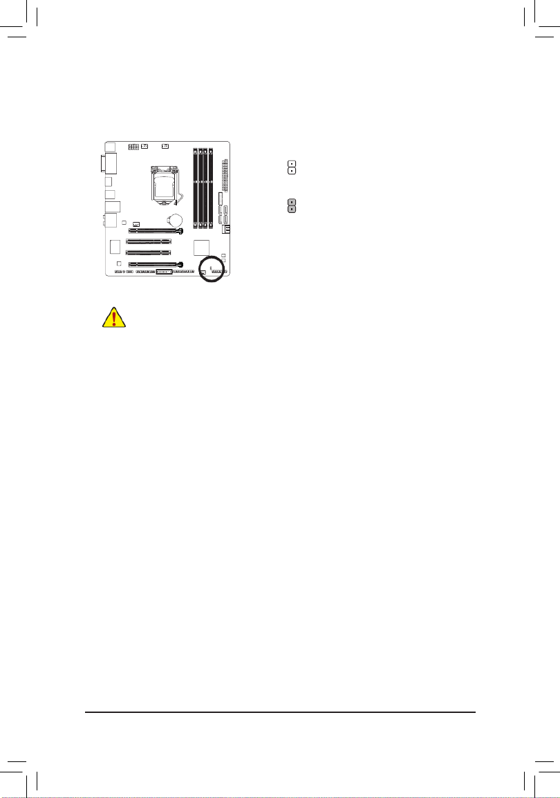
15) CLR_CMOS (Clear CMOS Jumper)
UsethisjumpertocleartheBIOScongurationsandresettheCMOSvaluestofactorydefaults.Toclear
the CMOS values, use a metal object like a screwdriver to touch the two pins for a few seconds.
Open:Normal
Short:ClearCMOSValues
•Always turn off your computer and unplug the power cord from the power outlet before clearing
the CMOS values.
•Aftersystemrestart,gotoBIOSSetuptoloadfactorydefaults(selectLoadOptimizedDefaults)or
manuallyconguretheBIOSsettings(refertoChapter2,"BIOSSetup,"forBIOScongurations).

Hardware Installation
- 30 -

- 31 -
BIOS Setup
BIOS (Basic Input and Output System) records hardware parameters of the system in the CMOS on the
motherboard.ItsmajorfunctionsincludeconductingthePower-OnSelf-Test(POST)duringsystemstartup,
saving system parameters and loading operating system, etc. BIOS includes a BIOS Setup program that allows
theusertomodifybasicsystemcongurationsettingsortoactivatecertainsystemfeatures.
Whenthepoweristurnedoff,thebatteryonthemotherboardsuppliesthenecessarypowertotheCMOSto
keepthecongurationvaluesintheCMOS.
ToaccesstheBIOSSetupprogram,pressthe<Delete>keyduringthePOSTwhenthepoweristurnedon.
To upgrade the BIOS, use either the GIGABYTE Q-Flash or @BIOS utility.
•Q-Flash allows the user to quickly and easily upgrade or back up BIOS without entering the operating system.
•@BIOSisaWindows-basedutilitythatsearchesanddownloadsthelatestversionofBIOSfromtheInternet
and updates the BIOS.
For instructions on using the Q-Flash and @BIOS utilities, refer to Chapter 4, "BIOS Update Utilities."
Chapter 2 BIOS Setup
•BecauseBIOSashingispotentiallyrisky, ifyoudonotencounter problemsusing thecurrent
versionof BIOS,itisrecommendedthat younotashtheBIOS.To ashtheBIOS,doitwith
caution.InadequateBIOSashingmayresultinsystemmalfunction.
•Itisrecommendedthatyounotalterthedefaultsettings(unlessyouneedto)topreventsystem
instability or other unexpected results. Inadequately altering the settings may result in system's
failure to boot. If this occurs, try to clear the CMOS values and reset the board to default values.
(Refertothe"LoadOptimizedDefaults"sectioninthischapterorintroductionsofthebattery/clear
CMOSjumperinChapter1forhowtocleartheCMOSvalues.)

BIOS Setup
- 32 -
2-1 Startup Screen
The following startup Logo screen will appear when the computer boots.
Function Keys:
<DEL>: BIOS SETUP\Q-FLASH
Pressthe<Delete>keytoenterBIOSSetuportoaccesstheQ-FlashutilityinBIOSSetup.
<F9>: SYSTEM INFORMATION
Pressthe<F9>keytodisplayyoursysteminformation.
<F12>: BOOT MENU
BootMenuallowsyoutosettherstbootdevicewithoutenteringBIOSSetup.InBootMenu,usetheup
arrow key <h i>orthedownarrowkey< >toselecttherstbootdevice,thenpress<Enter>toaccept.
The system will boot from the device immediately.
Note:ThesettinginBootMenuiseffectiveforonetimeonly.Aftersystemrestart,thedevicebootorder
will still be based on BIOS Setup settings.
<END>: Q-FLASH
Pressthe<End>keytoaccesstheQ-FlashutilitydirectlywithouthavingtoenterBIOSSetuprst.
Function Keys

- 33 -
BIOS Setup
Setup Menus
Function Keys
Help
Enter Q-Flash
Select Default
Language
CongurationItems Current Settings
2-2 The Main Menu
A. Windows Mode (Default)
DifferingfromtraditionalUEFIinterface,theWindowsModeprovidesafancyanduser-friendlyBIOSenvironment
where users can easily point and click through various settings and make adjustments for optimum performance.
InWindowsMode,youcanuseyourmousetomovethroughtheoptionmenusforquickcongurationoryou
can click under the Classic Setup Shortcutslistontherightofthescreenorpress<F2>toswitchtothe
traditional BIOS Setup screen.
B. Classic Setup
InClassicSetup,youcanpressthearrowkeysonyourkeyboardtomoveamongtheitemsandpress<Enter>
to accept or enter a sub-menu. Or you can use your mouse to select the item you want.
(Sample BIOS Version: Z87M-D3H F5a)
Switch to
Windows
Mode

BIOS Setup
- 34 -
•Whenthesystemisnotstableasusual,selecttheLoad Optimized Defaults item to set your
system to its defaults.
•The BIOS Setup menus described in this chapter are for reference only and may differ by BIOS
version.
BIOS Setup Menus
M.I.T.
Usethismenutoconguretheclock,frequency,andvoltagesofyourCPUandmemory,etc.Orcheckthe
system/CPU temperatures, voltages, and fan speeds.
System
UsethismenutocongurethedefaultlanguageusedbytheBIOSandsystemtimeanddate.Thismenu
also displays information on the devices connected to the SATA ports.
BIOS Features
Usethismenutocongurethedevicebootorder,advancedfeaturesavailableontheCPU,andtheprimary
display adapter.
Peripherals
Usethismenutocongureallperipheraldevices,suchasSATA,USB,integratedaudio,andintegrated
LAN,etc.
Power Management
Usethismenutocongureallthepower-savingfunctions.
Save & Exit
Save all the changes made in the BIOS Setup program to the CMOS and exit BIOS Setup. You can save
thecurrentBIOSsettingstoaproleorloadoptimizeddefaultsforoptimal-performancesystemoperations.
Classic Setup Function Keys
<f><g>Move the selection bar to select a setup menu
<h><i> Movetheselectionbartoselectancongurationitemonamenu
<Enter> Execute command or enter a menu
<+>/<PageUp> Increase the numeric value or make changes
<->/<PageDown> Decrease the numeric value or make changes
<F2> SwitchtoWindowsMode
<F5> Restore the previous BIOS settings for the current submenus
<F7> LoadtheOptimizedBIOSdefaultsettingsforthecurrentsubmenus
<F8> Access the Q-Flash utility
<F9> Display system information
<F10> Save all the changes and exit the BIOS Setup program
<F12> Capture the current screen as an image and save it to your USB drive
<Esc> Main Menu: Exit the BIOS Setup program
Submenus: Exit current submenu

- 35 -
BIOS Setup
2-3 M.I.T.
Whetherthesystemwillworkstablywiththeoverclock/overvoltagesettingsyoumadeisdependent
onyouroverallsystemcongurations.Incorrectlydoingoverclock/overvoltagemayresultindamage
to CPU, chipset, or memory and reduce the useful life of these components. This page is for advanced
users only and we recommend you not to alter the default settings to prevent system instability or
otherunexpectedresults.(Inadequatelyalteringthesettingsmayresultinsystem'sfailuretoboot.If
thisoccurs,cleartheCMOSvaluesandresettheboardtodefaultvalues.)
This section provides information on the BIOS version, CPU base clock, CPU frequency, memory frequency,
totalmemorysize,CPUtemperature,Vcore,andmemoryvoltage.

BIOS Setup
- 36 -
`M.I.T. Current Status
This screen provides information on CPU/memory frequencies/parameters.
`Advanced Frequency Settings
&Performance Boost (Note)
Provides you with ve different overclocking congurations. Options are: Medium, High, Turbo, Ultra,
Extreme.(Default:Auto)
& MCPU Base Clock
AllowsyoutomanuallysettheCPUbaseclockin0.01MHzincrements.(Default:Auto)
Important: It is highly recommended that the CPU frequency be set in accordance with the CPU
specications.
&Host/PCIe Clock Frequency (Note) M
Allowsyoutomanuallysetthehostclockfrequency(whichcontrolsCPU,PCIe,andmemoryfrequencies)
in0.01MHzincrements.ThisitemiscongurableonlywhenCPU Base Clock Manual is set to .
&Processor Base Clock (Gear Ratio) (Note) M
AllowsyoutoconguretheProcessor Base Clock Host/PCIe Clock Frequency by multiplying the by
severalpresethostclockmultipliers.ThisitemiscongurableonlywhenCPU Base Clock is enabled.
&Host Clock Value M
This value is determined by multiplying the value by the Host/PCIe Clock Frequency Processor Base
Clock(Gear Ratio) value.
&Processor Graphics Clock
Allowsyoutosettheonboardgraphicsclock.Theadjustablerangeisfrom400MHzto4000MHz.(Default:
Auto)
&CPU Upgrade (Note)
AllowsyoutosettheCPUfrequency.OptionsmayvarydependingontheCPUbeingused.(Default:Auto)
(Note) ThisitemispresentonlywhenyouinstallaCPUthatsupportsthisfeature.Formoreinformationabout
Intel® CPUs' unique features, please visit Intel's website.
MOnly for GA-Z87M-D3H.
- 37 -
BIOS Setup
(Note) ThisitemispresentonlywhenyouinstallaCPUthatsupportsthisfeature.Formoreinformationabout
Intel® CPUs' unique features, please visit Intel's website.
&CPU Clock Ratio, CPU Frequency
The settings above are synchronous to those under the same items on the Advanced Frequency Settings
menu.
&K OC (Note)
AllowsforincreasedperformancebyusingcertainCPUs.(Default:Auto)
&CPU PLL Selection
Allows you to set the CPU PLL. AutoletstheBIOSautomaticallycongurethissetting.(Default:Auto)
&Filter PLL Level
Allows you to set the Filter PLL. AutoletstheBIOSautomaticallycongurethissetting.(Default:Auto)
&Uncore Ratio
Allows you to set the CPU Uncore ratio. The adjustable range is dependent on the CPU being used.
&Uncore Frequency
Displays the current CPU Uncore frequency.
&Intel(R) Turbo Boost Technology (Note)
Allows you to determine whether to enable the Intel CPU Turbo Boost technology. lets the BIOS Auto
automaticallycongurethissetting.(Default:Auto)
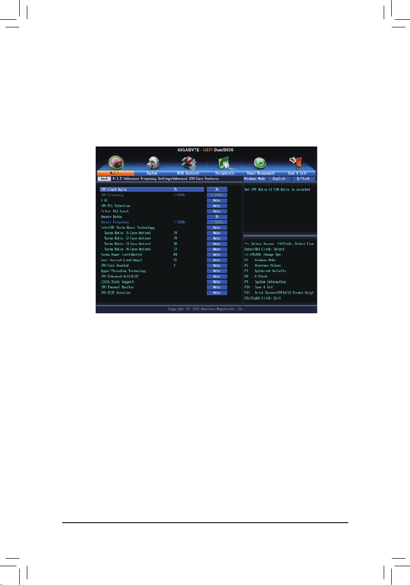
`Advanced CPU Core Features
&CPU Clock Ratio
Allows you to alter the clock ratio for the installed CPU. The adjustable range is dependent on the CPU
being installed.
&CPU Frequency
Displays the current operating CPU frequency.

BIOS Setup
- 38 -
&Turbo Ratio (1-Core Active~4-Core Active) (Note)
Allows you to set the CPU Turbo ratios for different number of active cores. Auto sets the CPU Turbo ratios
accordingtotheCPUspecications.(Default:Auto)
&Turbo Power Limit (Watts)
AllowsyoutosetapowerlimitforCPUTurbomode.WhentheCPUpowerconsumptionexceedsthe
speciedpowerlimit,theCPUwillautomaticallyreducethecorefrequencyinordertoreducethepower.
AutosetsthepowerlimitaccordingtotheCPUspecications.(Default:Auto)
&Core Current Limit (Amps)
AllowsyoutosetacurrentlimitforCPUTurbomode.WhentheCPUcurrentexceedsthespeciedcurrent
limit, the CPU will automatically reduce the core frequency in order to reduce the current. sets the Auto
powerlimitaccordingtotheCPUspecications.(Default:Auto)
&CPU Core Enabled (Note)
Allows you to determine whether to enable all CPU cores. AutoletstheBIOSautomaticallycongurethis
setting.(Default:Auto)
&Hyper-Threading Technology (Note)
Allows you to determine whether to enable multi-threading technology when using an Intel® CPU that
supports this function. This feature only works for operating systems that support multi-processor mode.
AutoletstheBIOSautomaticallycongurethissetting.(Default:Auto)
&CPU Enhanced Halt (C1E) (Note)
Enables or disables Intel®CPUEnhancedHalt(C1E)function,aCPUpower-savingfunctioninsystem
haltstate.Whenenabled,theCPUcorefrequencyandvoltagewillbereducedduringsystemhaltstateto
decrease power consumption. AutoletstheBIOSautomaticallycongurethissetting.(Default:Auto)
&C3/C6 State Support (Note)
AllowsyoutodeterminewhethertolettheCPUenterC3/C6modeinsystemhaltstate.Whenenabled,the
CPU core frequency and voltage will be reduced during system halt state to decrease power consumption.
The C3/C6 state is a more enhanced power-saving state than C1. AutoletstheBIOSautomaticallycongure
thissetting.(Default:Auto)
&CPU Thermal Monitor (Note)
Enables or disables Intel®ThermalMonitorfunction,aCPUoverheatingprotectionfunction.Whenenabled,
the CPU core frequency and voltage will be reduced when the CPU is overheated. lets the BIOS Auto
automaticallycongurethissetting.(Default:Auto)
&CPU EIST Function (Note)
Enables or disables Enhanced Intel®SpeedStepTechnology(EIST).DependingonCPUloading,Intel
EIST technology can dynamically and effectively lower the CPU voltage and core frequency to decrease
average power consumption and heat production. AutoletstheBIOSautomaticallycongurethissetting.
(Default:Auto)
(Note) ThisitemispresentonlywhenyouinstallaCPUthatsupportsthisfeature.Formoreinformationabout
Intel® CPUs' unique features, please visit Intel's website.

- 39 -
BIOS Setup
`Advanced Memory Settings
(Note) ThisitemispresentonlywhenyouinstallaCPUandamemorymodulethatsupportthisfeature.
&ExtremeMemoryProle(X.M.P.)(Note), System Memory Multiplier, Memory Frequency(MHz)
The settings above are synchronous to those under the same items on the Advanced Frequency Settings
menu.
&Memory Upgrade (Note)
Allowsyoutosetthememoryfrequency.Optionsmayvarydependingonthememorybeingused.(Default:
Auto)
&Performance Enhance
Allows the system to operate at three different performance levels.
Normal Letsthesystemoperateatitsbasicperformancelevel.
Turbo Letsthesystemoperateatitsgoodperformancelevel.(Default)
Extreme Lets the system operate at its best performance level.
&ExtremeMemoryProle(X.M.P.)(Note)
AllowstheBIOStoreadtheSPDdataonXMPmemorymodule(s)toenhancememoryperformancewhen
enabled.
Disabled Disablesthisfunction.(Default)
Prole1 UsesProle1settings.
Prole2(Note) UsesProle2settings.
&System Memory Multiplier
Allows you to set the system memory multiplier. sets memory multiplier according to memory SPD Auto
data.(Default:Auto)
&Memory Frequency (MHz)
Therstmemoryfrequencyvalueisthenormaloperatingfrequencyofthememorybeingused;thesecond
is the memory frequency that is automatically adjusted according to the settings.System Memory Multiplier

BIOS Setup
- 40 -
This sub-menu provides memory timing settings for each channel of memory. The respective timing setting
screensarecongurableonlywhen .Note:YoursystemDRAM Timing Selectable is set to Quick or Expert
may become unstable or fail to boot after you make changes on the memory timings. If this occurs, please reset
theboardtodefaultvaluesbyloadingoptimizeddefaultsorclearingtheCMOSvalues.
`Channel A/B Timing Settings
&DRAM Timing Selectable
Quick Expert and allows the Channel Interleaving, Rank Interleaving, and memory timing settings below
tobecongurable.Optionsare:Auto(default),Quick,Expert.
&ProleDDRVoltage
Whenusinganon-XMPmemorymoduleorExtremeMemoryProle(X.M.P.) is set to Disabled, this item
will display as 1.50V.WhenExtremeMemoryProle(X.M.P.) Prole1 Prole2 is set to or , this item will
displaythevaluebasedontheSPDdataontheXMPmemory.
&Channel Interleaving
Enables or disables memory channel interleaving. allows the system to simultaneously access Enabled
different channels of the memory to increase memory performance and stability. lets the BIOS Auto
automaticallycongurethissetting.(Default:Auto)
&Rank Interleaving
Enables or disables memory rank interleaving. allows the system to simultaneously access different Enabled
ranks of the memory to increase memory performance and stability. lets the BIOS automatically Auto
congurethissetting.(Default:Auto)

- 41 -
BIOS Setup
`CPU Core Voltage Control
This section provides CPU voltage control options.
`Chipset Voltage Control
This section provides Chipset voltage control options.
`DRAM Voltage Control
This section provides memory voltage control options.
`Advanced Voltage Settings
BIOS Setup
- 42 -
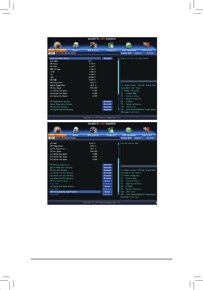
`PC Health Status
&Reset Case Open Status
Disabled Keeps or clears the record of previous chassis intrusion status. (Default)
Enabled Clears the record of previous chassis intrusion status and the Case Open eld will show
"No" at next boot.
&Case Open
Displays the detection status of the chassis intrusion detection device attached to the motherboard CI
header. If the system chassis cover is removed, this eld will show "Yes", otherwise it will show "No". To
clear the chassis intrusion status record, set to , save the settings to Reset Case Open Status Enabled
the CMOS, and then restart your system.

- 43 -
BIOS Setup
&CPU Vcore/CPU VRIN/DRAM Voltage/+3.3V/+5V/+12V/CPU VAXG
Displays the current system voltages.
&CPU/System Temperature
Displays current CPU/system temperature.
&CPU/System FAN Speed
Displays current CPU/system fan speeds.
&CPU/System Warning Temperature
Sets the warning threshold for CPU/system temperature. When CPU/system temperature exceeds
thethreshold, BIOSwill emitwarningsound. Optionsare: Disabled(default), 60oC/140oF, 70oC/158oF,
80oC/176oF, 90oC/194oF.
&CPU/System FAN Fail Warning
Allows the system to emit warning sound if the fan is not connected or fails. Check the fan condition or fan
connectionwhenthisoccurs.(Default:Disabled)
&CPU Fan Speed Control
Allows you to determine whether to enable the fan speed control function and adjust the fan speed.
Normal AllowsthefantorunatdifferentspeedsaccordingtotheCPUtemperature.Youcanadjust
thefanspeedwithEasyTunebasedonyoursystemrequirements.(Default)
Silent Allows the fan to run at slow speeds.
Manual Allows you to control the fan speed under the item.Slope PWM
Disabled Allows the fan to run at full speeds.
&Slope PWM
Allowsyoutocontrolthefanspeed.ThisitemiscongurableonlywhenCPU Fan Speed Control is set
to Manual.Optionsare:0.75PWMvalue/oC~2.50PWMvalue/oC.
&1st System Fan Speed Control (SYS_FAN1 Connector)
Allows you to determine whether to enable the fan speed control function and adjust the fan speed.
Normal Allowsthefantorunatdifferentspeedsaccordingtothesystemtemperature.Youcanadjust
thefanspeedwithEasyTunebasedonyoursystemrequirements.(Default)
Silent Allows the fan to run at slow speeds.
Manual Allows you to control the fan speed under the item.Slope PWM
Disabled Allows the fan to run at full speeds.
&Slope PWM
Allowsyoutocontrolthefanspeed.Thisitemiscongurableonlywhen1st System Fan Speed Control
is set to Manual.Optionsare:0.75PWMvalue/oC~2.50PWMvalue/oC.
&2nd/3rd System Fan Speed Control (SYS_FAN2/SYS_FAN3 Connectors)
Allows you to determine whether to enable the fan speed control function and adjust the fan speed.
Normal Allowsthefantorunatdifferentspeedsaccordingtothesystemtemperature.Youcanadjust
thefanspeedwithEasyTunebasedonyoursystemrequirements.(Default)
Silent Allows the fan to run at slow speeds.
Manual Allows you to control the fan speed under the item.Slope PWM
Disabled Allows the fan to run at full speeds.
&Slope PWM
Allowsyouto controlthe fanspeed.Thisitemiscongurableonlywhen 2nd/3rd System Fan Speed
Control Manual is set to .Optionsare:0.75PWMvalue/oC~2.50PWMvalue/oC.

BIOS Setup
- 44 -
`Miscellaneous Settings
&PEGGen3SlotConguration
Allows you to set the operation mode of the PCI Express slots to Gen 1, Gen 2, or Gen 3. Actual operation
modeissubjecttothehardwarespecicationofeachslot.Forexample,thePCIExpressx1slotscan
supportuptoGen2modeonly.AutoletstheBIOSautomaticallycongurethissetting.(Default:Auto)
&Legacy BenchMark Enhancement
Allowsyoutodeterminewhethertoenhancesomelegacybenchmarkperformance.(Default:Disabled)

- 45 -
BIOS Setup
2-4 System
This section provides information on your CPU, memory, motherboard model, and BIOS version. You can also
select the default language used by the BIOS and manually set the system time.
&System Language
Selects the default language used by the BIOS.
&System Date
Setsthesystemdate.Thedateformatisweek(read-only),month,date,andyear.Use<Enter>toswitch
betweentheMonth,Date,andYeareldsandusethe<PageUp>or<PageDown>keytosetthedesired
value.
&System Time
Sets the system time. The time format is hour, minute, and second. For example, 1 p.m. is 13:0:0. Use
<Enter>toswitchbetweentheHour,Minute,andSecondeldsandusethe<PageUp>or<PageDown>
key to set the desired value.
&Access Level
Displaysthecurrentaccessleveldependingonthetypeofpasswordprotectionused.(Ifnopasswordis
set, the default will display as Administrator.)TheAdministratorlevelallowsyoutomakechangestoall
BIOSsettings;theUserlevelonlyallowsyoutomakechangestocertainBIOSsettingsbutnotall.

BIOS Setup
- 46 -
2-5 BIOS Features
&Boot Option Priorities
Speciestheoverallbootorderfromtheavailabledevices.Forexample,youcansetharddriveasthe
rstpriority(BootOption#1)andDVDROMdriveasthesecondpriority(BootOption#2).Thelistonly
displaysthedevicewiththehighestpriorityforaspecictype.Forexample,onlyharddrivedenedasthe
rstpriorityontheHard Drive BBS Priorities submenu will be presented here.
RemovablestoragedevicesthatsupportGPTformatwillbeprexedwith"UEFI:"stringonthebootdevice
list.TobootfromanoperatingsystemthatsupportsGPTpartitioning,selectthedeviceprexedwith"UEFI:"
string.
OrifyouwanttoinstallanoperatingsystemthatsupportsGPTpartitioningsuchasWindows764-bit,select
theopticaldrivethatcontainstheWindows764-bitinstallationdiskandisprexedwith"UEFI:"string.
&Hard Drive/CD/DVD ROM Drive/Floppy Drive/Network Device BBS Priorities
Speciesthebootorderforaspecicdevicetype,suchasharddrives,opticaldrives,oppydiskdrives,
anddevicesthatsupportBootfromLANfunction,etc.Press<Enter>onthisitemtoenterthesubmenuthat
presents the devices of the same type that are connected. This item is present only if at least one device
for this type is installed.
&Bootup NumLock State
EnablesordisablesNumlockfeatureonthenumerickeypad ofthekeyboardafterthePOST.(Default:
Enabled)
&Security Option
Specieswhetherapasswordisrequiredeverytimethesystemboots,oronlywhenyouenterBIOSSetup.
Afterconguringthisitem,setthepassword(s)undertheAdministratorPassword/UserPassworditem.
Setup A password is only required for entering the BIOS Setup program.
System A password is required for booting the system and for entering the BIOS Setup program.
(Default)

- 47 -
BIOS Setup
&Full Screen LOGO Show
Allows you to determine whether to display the GIGABYTE Logo at system startup. skips the Disabled
GIGABYTELogowhenthesystemstartsup.(Default:Enabled)
&Fast Boot
Enables or disables Fast Boot to shorten the OS boot process. provides the fastest bootup Ultra Fast
speed.(Default:Disabled)
&VGA Support
Allows you to select which type of operating system to boot.
Auto Enables legacy option ROM only.
EFIDriver EnablesEFIoptionROM.(Default)
ThisitemiscongurableonlywhenFast Boot Enabled Ultra Fast is set to or .
&USB Support
Disabled All USB devices are disabled before the OS boot process completes.
Full Initial All USB devices are functional in the operating system and during the POST.
PartialInitial PartoftheUSBdevicesaredisabledbeforetheOSbootprocesscompletes.(Default)
ThisitemiscongurableonlywhenFast Boot Fast Boot is set to Enabled. This item is disabled when is
set to .Ultra Fast
&PS2 Devices Support
Disabled All PS/2 devices are disabled before the OS boot process completes.
Enabled AllPS/2devicesarefunctionalintheoperatingsystemandduringthePOST.(Default)
ThisitemiscongurableonlywhenFast Boot Fast Boot is set to Enabled. This item is disabled when is
set to .Ultra Fast
&NetWork Stack Driver Support
Disabled Disablesbootingfromthenetwork.(Default)
Enabled Enables booting from the network.
ThisitemiscongurableonlywhenFast Boot Enabled Ultra Fast is set to or .
&Next Boot After AC Power Loss
NormalBoot EnablesnormalbootupuponthereturnoftheACpower.(Default)
Fast Boot Keeps the Fast Boot settings upon the return of the AC power.
ThisitemiscongurableonlywhenFast Boot Enabled Ultra Fast is set to or .
&Limit CPUID Maximum (Note)
Allows you to determine whether to limit CPUID maximum value. Set this item to DisabledforWindowsXP
operatingsystem;setthisitemtoEnabledforlegacyoperatingsystemsuchasWindowsNT4.0.(Default:
Disabled)
&Execute Disable Bit (Note)
Enables or disables Intel
®
Execute Disable Bit function. This function may enhance protection for the
computer,reducing exposure to viruses and malicious buffer overow attackswhen working with its
supportingsoftwareandsystem.(Default:Enabled)
&Intel Virtualization Technology (Note)
Enables or disables Intel
®
VirtualizationTechnology.Virtualizationenhanced by Intel ®
Virtualization
Technology will allow a platform to run multiple operating systems and applications in independent partitions.
Withvirtualization,onecomputersystemcanfunctionasmultiplevirtualsystems.(Default:Enabled)
(Note) ThisitemispresentonlywhenyouinstallaCPUthatsupportsthisfeature.Formoreinformationabout
Intel
®
CPUs' unique features, please visit Intel's website.

BIOS Setup
- 48 -
& Intel TXT(LT) Support
(Note)
Enables or disables Intel®
Trusted Execution Technology (Intel
®
TXT). Intel®
Trusted Execution Technology
provides a hardware-based security foundation. (Default: Disabled)
& jDynamic Storage Accelerator
Enables or disables Intel® Dynamic Storage Accelerator. When enabled, the hard drive I/O performance
will be adjusted according to hard drive load. (Default: Disabled)
& VT-d
(Note)
Enables or disablesIntel® Virtualization Technology for Directed I/O. (Default: Enabled)
& OS Type
Allows you to select the operating system to be installed. Set this item to for Windows 8 Windows 8
operating system. (Default: Other OS)
& CSM Support
Enables or disables UEFI CSM (Compatibility Support Module) to support a legacy PC boot process.
Always Enables UEFI CSM. (Default)
Never Disables UEFI CSM and supports UEFI BIOS boot process only.
ThisitemiscongurableonlywhenOS Type Windows 8 Windows 8 WHQL is set to or .
& Boot Mode Selection
Allows you to select which type of operating system to boot.
UEFI and Legacy Allows booting from operating systems that support legacy option ROM or UEFI
option ROM. (Default)
Legacy Only Allows booting from operating systems that only support legacy Option ROM.
UEFI Only Allows booting from operating systems that only support UEFI Option ROM.
ThisitemiscongurableonlywhenCSMSupportissettoAlways.
& LAN PXE Boot Option ROM
Allows you to select whether to enable the legacy option ROM for the LAN controller. (Default: Disabled)
ThisitemiscongurableonlywhenCSM Support Always is set to .
& Storage Boot Option Control
Allows you to select whether to enable the UEFI or legacy option ROM for the storage device controller.
Disabled Disables option ROM.
UEFI Only Enables UEFI option ROM only.
Legacy Only Enables legacy option ROM only. (Default)
LegacyFirst EnablesLegacyOptionROMrst.
UEFIFirst EnablesUEFIOptionROMrst.
ThisitemiscongurableonlywhenCSMSupportissettoAlways.
& Other PCI Device ROM Priority
Allows you to select whether to enable the UEFI or Legacy option ROM for the PCI device controller other
than the LAN, storage device, and graphics controllers.
UEFI OpROM Enables UEFI option ROM only. (Default)
Legacy OpROM Enables legacy option ROM only.
(Note) This item is present only when you install a CPU that supports this feature. For more information about
Intel® CPUs' unique features, please visit Intel's website.
jOnly for GA-Z87M-D3H.

- 49 -
BIOS Setup
&Network stack
Disables or enables booting from the network to install a GPT format OS, such as installing the OS from
theWindowsDeploymentServicesserver.(Default:Disabled)
&Ipv6 PXE Support
EnablesordisablesIPv6PXESupport.ThisitemiscongurableonlywhenNetwork stack is enabled.
&Ipv4 PXE Support
EnablesordisablesIPv4PXESupport.ThisitemiscongurableonlywhenNetwork stack is enabled.
&Administrator Password
Allowsyoutocongureanadministratorpassword.Press<Enter>onthisitem,typethepassword,and
thenpress<Enter>.Youwillberequestedtoconrmthepassword.Typethepasswordagainandpress
<Enter>.Youmustentertheadministratorpassword(oruserpassword)atsystemstartupandwhenentering
BIOS Setup. Differing from the user password, the administrator password allows you to make changes to
all BIOS settings.
&User Password
Allowsyoutocongureauserpassword.Press<Enter>onthisitem,typethepassword,andthenpress
<Enter>.Youwillberequestedtoconrmthepassword.Typethepasswordagain andpress<Enter>.
Youmustentertheadministratorpassword(oruserpassword)atsystemstartupandwhenenteringBIOS
Setup. However, the user password only allows you to make changes to certain BIOS settings but not all.
Tocancelthepassword,press<Enter>onthepassworditemandwhenrequestedforthepassword,enterthe
correctonerst.Whenpromptedforanewpassword,press<Enter>withoutenteringanypassword.Press
<Enter>againwhenpromptedtoconrm.

BIOS Setup
- 50 -
2-6 Peripherals
&Init Display First
SpeciestherstinitiationofthemonitordisplayfromtheinstalledPCIgraphicscard,PCIExpressgraphics
card or the onboard graphics.
IGFX Setstheonboardgraphicsastherstdisplay.
PCIe1Slot SetsthegraphicscardonthePCIEX16slotastherstdisplay.(Default)
PCIe2Slot SetsthegraphicscardonthePCIEX4slotastherstdisplay.
PCI SetsthegraphicscardonthePCIslotastherstdisplay.
&XHCI Mode
Allows you to determine the operating mode for the xHCI controller in OS.
Smart Auto This mode is available only when the BIOS supports the xHCI controller in the pre-boot
environment. This mode is similar to , but it adds the capability to route the ports Auto
toxHCIorEHCIaccordingtosettingusedinpreviousboots(fornon-G3boot)inthe
pre-boot environment. This allows the use of USB 3.0 devices prior to OS boot. xHCI
controller enabling and rerouting should follow the steps in , when previous boot Auto
routsportstoEHCI.Note:ThisistherecommendedmodewhenBIOShasxHCIpre-
bootsupport.(Default)
Auto BIOS routes the sharable ports to EHCI controller. Then it uses ACPI protocols to
provideanoptiontoenablethexHCIcontrollerandreroutethesharableports.Note:
ThisistherecommendedmodewhenBIOSdoesNOThavexHCIpre-bootsupport.
Enabled All shared ports are eventually routed to the xHCI controller during the BIOS boot process.
If BIOS does not have pre-boot support for the xHCI controller, it should initially route
the sharable ports to the EHCI controller and then prior to OS boot it should route the
portstoxHCIcontroller.Note:OShastoprovidesupportforthexHCIcontrollerinthis
mode. If the OS does not provide support, all sharable ports won't work.
Disabled The USB 3.0 ports are routed to the EHCI controller and the xHCI controller is turned
off. All USB 3.0 devices function as High Speed devices regardless of xHCI software
support/availability.

- 51 -
BIOS Setup
Manual Allows you to determine whether to rout the USB 3.0 ports to the xHCI or EHCI controller
before booting to OS, and also provides you with options to manually rout each USB
3.0/2.0 port to xHCI or EHCI.
&Audio Controller
Enablesordisablestheonboardaudiofunction.(Default:Auto)
If you wish to install a 3rd party add-in audio card instead of using the onboard audio, set this item to
Disabled.
&Internal Graphics
Enablesordisablestheonboardgraphicsfunction.(Default:Enabled)
&Internal Graphics Memory Size
Allowsyoutosettheonboardgraphicsmemorysize.Optionsare:32M~1024M.(Default:64M)
&DVMT Total Memory Size
AllowsyoutoallocatetheDVMTmemorysizeoftheonboardgraphics.Optionsare:128M,256M,MAX.
(Default:MAX)
&Intel(R) Rapid Start Technology
Enables or disables Intel®RapidStartTechnology.(Default:Disabled)
&Legacy USB Support
AllowsUSBkeyboard/mousetobeusedinMS-DOS.(Default:Enabled)
&XHCI Hand-off
Determines whether toenableXHCIHand-offfeatureforan operatingsystem withoutXHCI Hand-off
support.(Default:Enabled)
&EHCI Hand-off
Determines whether to enable EHCI Hand-off feature for an operating system without EHCI Hand-off
support.(Default:Disabled)
&USB Storage Devices
Displays a list of connected USB mass storage devices. This item appears only when a USB storage device
isinstalled.(Default:Auto)
&OnBoard LAN Controller#1
EnablesordisablestheonboardLANfunction.(Default:Enabled)
Ifyouwishtoinstalla3rdpartyadd-innetworkcardinsteadofusingtheonboardLAN,setthisitemto
Disabled.
BIOS Setup
- 52 -
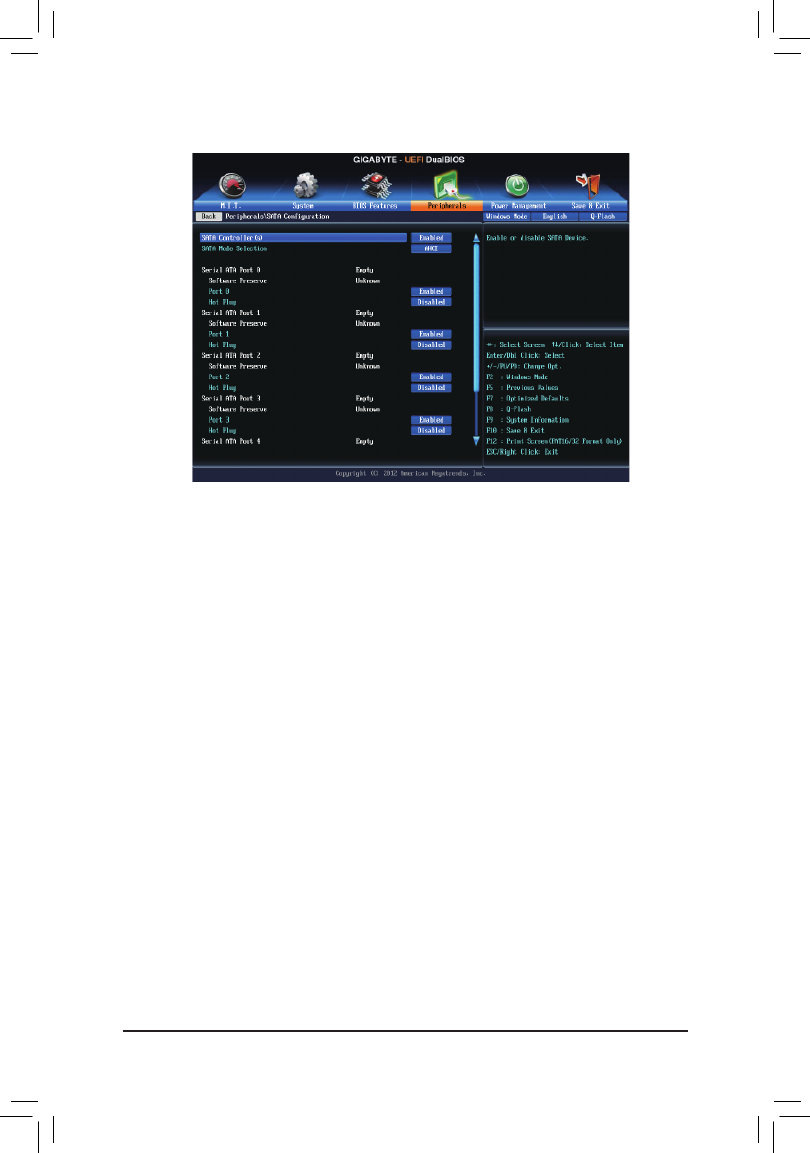
`SATA Conguration
&SATA Controller(s) (Intel® Z87 /H87j k Chipset)
Enables or disables the integrated SATA controllers. (Default: Enabled)
&SATA Mode Selection (Intel® Z87 /H87j k Chipset)
EnablesordisablesRAIDfortheSATAcontrollersintegratedintheIntelChipsetorcongurestheSATA
controllers to AHCI mode.
IDE CongurestheSATAcontrollertoIDEmode.
RAID Enables RAID for the SATA controller.
AHCI Conguresthe SATAcontrollers toAHCImode.AdvancedHostController Interface
(AHCI)isaninterfacespecicationthatallowsthestoragedrivertoenableadvanced
SerialATAfeaturessuchasNativeCommandQueuingandhotplug.(Default)
`Serial ATA Port 0/1/2/3/4/5
&Port 0/1/2/3/4/5
Enables or disables each SATA port. (Default: Enabled)
&Hot plug
Enables or disable the hot plug capability for each SATA port. (Default: Disabled)
`Super IO Conguration
Thissectionprovidesinformationon thesuperI/Ochipandallowsyoutocongure theserialportand
parallel port.
&Serial Port A
Enables or disables the onboard serial port. (Default: Enabled)
&Parallel Port
Enables or disables the onboard parallel port. (Default: Enabled)
jOnlyforGA-Z87M-D3H.
kOnlyforGA-H87M-D3H.

- 53 -
BIOS Setup
&Device Mode
ThisitemiscongurableonlywhenParallel Port is set to Enabled. Selects an operating mode for the
onboardparallel(LPT)port.(Default),EPPMode(EnhancedParallelPort),ECPMode(ExtendedCapabilities
Port),EPPMode&ECPMode.
`Intel(R) Smart Connect Technology
&ISCT Support
Enables or disables Intel®SmartConnectTechnology.(Default:Disabled)
`Realtek PCIe GBE Family Controller
Thissub-menuprovidesinformationonLANconguration.

BIOS Setup
- 54 -
2-7 Power Management
&Resume by Alarm
Determineswhethertopoweronthesystematadesiredtime.(Default:Disabled)
If enabled, set the date and time as following:
Wakeupday:Turnonthesystemataspecictimeoneachdayoronaspecicdayinamonth.
Wakeuphour/minute/second:Setthetimeatwhichthesystemwillbepoweredonautomatically.
Note:Whenusingthisfunction,avoidinadequateshutdownfromtheoperatingsystemorremovalofthe
AC power, or the settings may not be effective.
&ErP
DetermineswhethertoletthesystemconsumeleastpowerinS5(shutdown)state.(Default:Disabled)
Note:WhenthisitemissettoEnabled, the following functions will become unavailable: PME event wake
up,poweronbymouse,poweronbykeyboard,andwakeonLAN.
&Soft-Off by PWR-BTTN
ConguresthewaytoturnoffthecomputerinMS-DOSmodeusingthepowerbutton.
Instant-Off Pressthepowerbuttonandthenthesystemwillbeturnedoffinstantly.(Default)
Delay 4 Sec Press and hold the power button for 4 seconds to turn off the system. If the power
button is pressed for less than 4 seconds, the system will enter suspend mode.
&RC6(Render Standby)
Allows you to determine whether to let the onboard graphics enter standby mode to decrease power
consumption.(Default:Enabled)
&AC BACK
Determines the state of the system after the return of power from an AC power loss.
Memory The system returns to its last known awake state upon the return of the AC power.
Always On The system is turned on upon the return of the AC power.
AlwaysOff ThesystemstaysoffuponthereturnoftheACpower.(Default)

- 55 -
BIOS Setup
&Power On By Keyboard
Allows the system to be turned on by a PS/2 keyboard wake-up event.
Note:Tousethisfunction,youneedanATXpowersupplyprovidingatleast1Aonthe+5VSBlead.
Disabled Disablesthisfunction.(Default)
Password Set a password with 1~5 characters to turn on the system.
Keyboard98 PressPOWERbuttonontheWindows98keyboardtoturnonthesystem.
Any Key Press any key to turn on the system.
&Power On Password
Set the password when is set to .Power On By Keyboard Password
Press<Enter>onthisitemandsetapasswordwithupto5charactersandthenpress<Enter>toaccept.
Toturnonthesystem,enterthepasswordandpress<Enter>.
Note:Tocancelthepassword,press<Enter>onthisitem.Whenpromptedforthepassword,press<Enter>
again without entering the password to clear the password settings.
&Power On By Mouse
Allows the system to be turned on by a PS/2 mouse wake-up event.
Note:Tousethisfunction,youneedanATXpowersupplyprovidingatleast1Aonthe+5VSBlead.
Disabled Disablesthisfunction.(Default)
Move Move the mouse to turn on the system.
Double Click Double click on left button on the mouse to turn on the system.
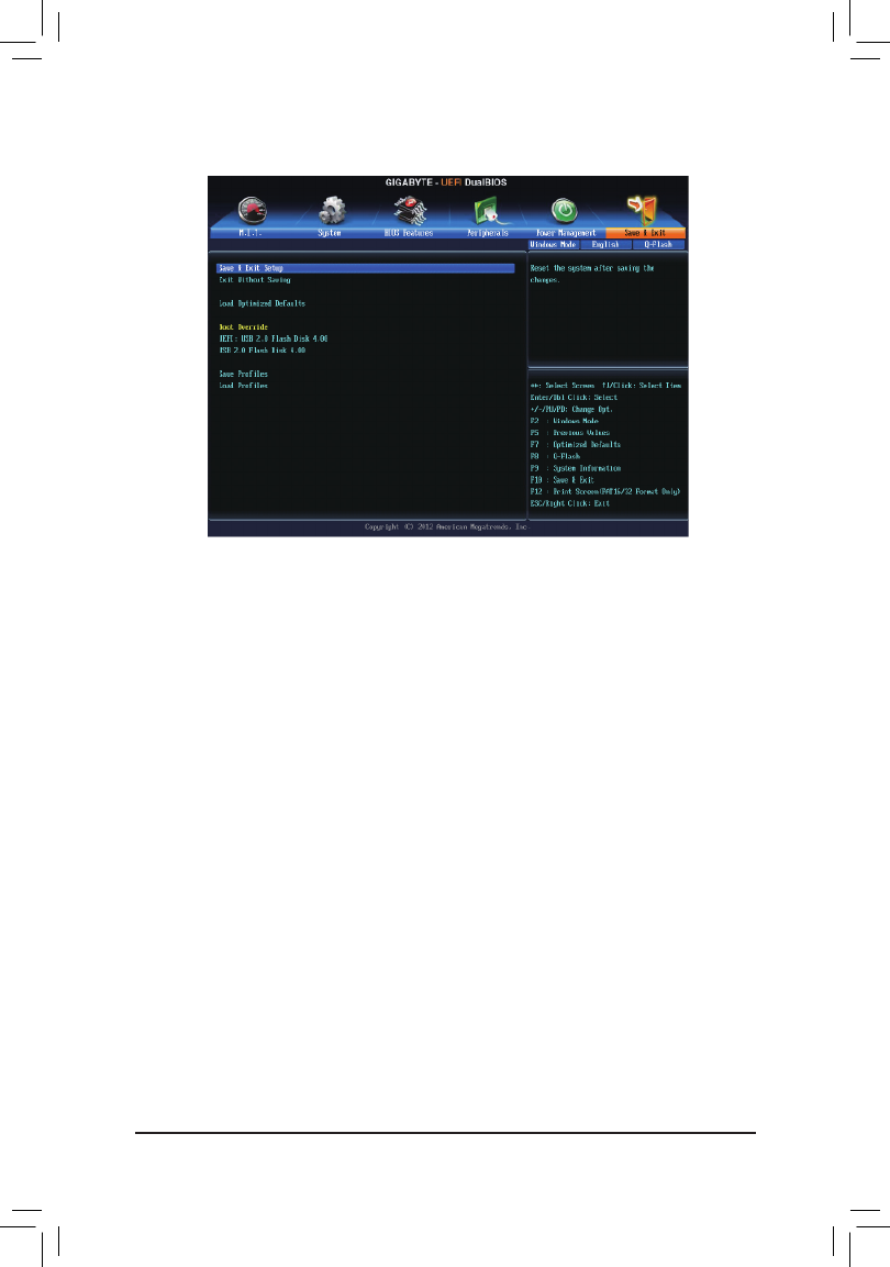
BIOS Setup
- 56 -
2-8 Save & Exit
&Save & Exit Setup
Press<Enter>onthisitemandselectYes. This saves the changes to the CMOS and exits the BIOS Setup
program. Select Noorpress<Esc>toreturntotheBIOSSetupMainMenu.
&Exit Without Saving
Press<Enter>onthisitemandselectYes. This exits the BIOS Setup without saving the changes made
in BIOS Setup to the CMOS. Select Noorpress<Esc>toreturntotheBIOSSetupMainMenu.
&Load Optimized Defaults
Press<Enter>onthisitemandselectYes to load the optimal BIOS default settings. The BIOS defaults
settingshelpthesystemtooperateinoptimumstate.AlwaysloadtheOptimizeddefaultsafterupdating
the BIOS or after clearing the CMOS values.
&Boot Override
Allowsyoutoselectadevicetobootimmediately.Press<Enter>onthedeviceyouselectandselectYes
toconrm.Yoursystemwillrestartautomaticallyandbootfromthatdevice.
&SaveProles
ThisfunctionallowsyoutosavethecurrentBIOSsettingstoaprole.Youcancreateupto4prolesand
saveasSetupProle1~SetupProle4.Press<Enter>tocomplete.
&LoadProles
If your system becomes unstable and you have loaded the BIOS default settings, you can use this function
toloadtheBIOSsettingsfromaprolecreatedbefore, withoutthehasslesof reconguringtheBIOS
settings.Firstselecttheproleyouwishtoloadandthenpress<Enter>tocomplete.

- 57 -
Conguring SATA Hard Drive(s)
Chapter3 ConguringSATAHardDrive(s)
TocongureSATAharddrive(s),followthestepsbelow:
A. InstallSATAharddrive(s)inyourcomputer.
B. CongureSATAcontrollermodeinBIOSSetup.
C. CongureaRAIDarrayinRAIDBIOS.(Note1)
D. Install the SATA RAID/AHCI driver and operating system. (Note2)
Before you begin
Please prepare:
•AtleasttwoSATAharddrives(toensureoptimalperformance,itisrecommendedthatyouusetwoharddrives
withidenticalmodelandcapacity).IfyoudonotwanttocreateRAID,youmayprepareonlyoneharddrive.
•Windows8/7setupdisk.
•Motherboard driver disk.
•A USB thumb drivev
RAID Levels
(Note1) SkipthisstepifyoudonotwanttocreateRAIDarrayontheSATAcontroller.
(Note2) RequiredwhentheSATAcontrollerissettoAHCIorRAIDmode.
3-1 ConguringSATAControllers
A. Installing SATA hard drive(s) in your computer
Attach one end of the SATA signal cable to the rear of the SATA hard drive and the other end to available SATA
port on the motherboard. Then connect the power connector from your power supply to the hard drive.
RAID 0 RAID 1 RAID 5 RAID 10
Minimum
NumberofHard
Drives
≥2 ≥3 ≥42
Array Capacity Numberofhard
drives*Sizeofthe
smallest drive
Sizeofthesmallest
drive
(Numberofhard
drives-1)*Sizeof
the smallest drive
(Numberofhard
drives/2)*Sizeofthe
smallest drive
Fault Tolerance No Yes Yes Yes
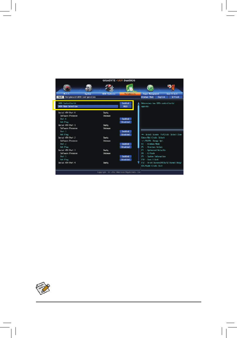
Conguring SATA Hard Drive(s)
- 58 -
The BIOS Setup menus described in this section may differ from the exact settings for your motherboard.
The actual BIOS Setup menu options you will see shall depend on the motherboard you have and
the BIOS version.
B.ConguringSATAcontrollermodeinBIOSSetup
MakesuretoconguretheSATAcontrollermodecorrectlyinsystemBIOSSetup.
Step 1:
Turnonyourcomputerandpress<Delete>toenterBIOSSetupduringthePOST(Power-OnSelf-Test).Goto
Peripherals\SATAConguration, make sure SATA Controllers is enabled. To create RAID, set SATA Mode
Selection RAID IDE AHCI to (Figure1).IfyoudonotwanttocreateRAID,setthisitemto or .
Step 2:
IfyouwanttocongureUEFIRAID,followthestepsin"C-1."ToenterthelegacyRAIDROM,savethesettings
and exit BIOS Setup. Refer to "C-2" for more information.
Figure 1

- 59 -
Conguring SATA Hard Drive(s)
C-1.UEFIRAIDConguration
ThismodesupportsWindows864-bitinstallationonly.
Step 1:
In BIOS Setup, go to and set BIOS Features OS Type Windows 8 CSM Support Never to and to .(Figure2)
Save the changes and exit BIOS Setup.
Step 2:
After the system reboot, enter BIOS Setup again. Then enter the Peripherals\Intel(R) Rapid Storage Technology
sub-menu(Figure3).
Figure 2
Figure 3

Conguring SATA Hard Drive(s)
- 60 -
Step 3:
On the Intel(R) Rapid Storage Technologymenu,press<Enter>onCreate RAID Volume to enter the Create
RAID Volumescreen.Enteravolumenamewith1~16letters(letterscannotbespecialcharacters)underthe
Nameitemandpress<Enter>.Then,selectaRAIDlevel(Figure4).RAIDlevelssupportedincludeRAID0,
RAID1,RAID10,andRAID5(theselectionsavailabledependonthenumberoftheharddrivesbeinginstalled).
Next,usethedownarrowkeytomovetoSelect Disks.
Step 4:
Under Select Disksitem,selecttheharddrivestobeincludedintheRAIDarray.Pressthe<Space>keyon
theharddrivestobeselected(selectedharddrivesaremarkedwith"X").Thensetthestripeblocksize(Figure
5).Thestripeblocksizecanbesetfrom4KBto128KB.Onceyouhaveselectedthestripeblocksize,set
the volume capacity.
Figure 4
Figure 5

- 61 -
Conguring SATA Hard Drive(s)
Step 5:
After setting the capacity, move to Create Volumeandpress<Enter>tobegin.(Figure6)
After completing, you'll be brought back to the Intel(R) Rapid Storage Technology RAID Volumes screen. Under
youcanseethenewRAIDvolume.Toseemoredetailedinformation,press<Enter>onthevolumetocheck
forinformationonRAIDlevel,stripeblocksize,arrayname,andarraycapacity,etc.(Figure7)
Figure 6
Figure 7

Conguring SATA Hard Drive(s)
- 62 -
Delete RAID Volume
TodeleteaRAIDarray,press<Enter>onthevolumetobedeletedontheIntel(R) Rapid Storage Technology
screen. After entering the to enter the screen. RAID VOLUME INFOscreen,press<Enter>onDelete Delete
Press<Enter>on (Figure8).Yes
Figure 8

- 63 -
Conguring SATA Hard Drive(s)
C-2.ConguringLegacyRAIDROM
Enter the Intel®legacyRAIDBIOSsetuputilitytocongureaRAIDarray.Skipthisstepandproceedwiththe
installationofWindowsoperatingsystemforanon-RAIDconguration.
Step 1:
After the POST memory test begins and before the operating system boot begins, look for a message which says
"Press<Ctrl-I>toenterCongurationUtility"(Figure9).Press<Ctrl>+<I>toentertheRAIDCongurationUtility.
Figure 9
Step 2:
Afteryoupress<Ctrl>+<I>,the screenwillappear(Figure10).MAIN MENU
Create RAID Volume
If you want to create a RAID array, select Create RAID Volume MAIN MENU in andpress<Enter>.
Figure 10
Intel(R) Rapid Storage Technology - Option ROM - 12.0.0.1783
Copyright(C) 2003-13 Intel Corporation. All Rights Reserved.
RAID Volumes :
None dened.
Physical Devices :
ID Device Model Serial # Size Type/Status(Vol ID)
0 ST3120026AS 3JT354CP 111.7GB Non-RAID Disk
1 ST3120026AS 3JT329JX 111.7GB Non-RAID Disk
Press <CTRL - I> to enter Conguration Utility..
Intel(R) Rapid Storage Technology - Option ROM - 12.0.0.1783
Copyright(C) 2003-13 Intel Corporation. All Rights Reserved.
4. Recovery Volume Options
5. Acceleration Options
6. Exit
RAID Volumes :
None dened.
Physical Deivces :
ID Device Model Serial # Size Type/Status(Vol ID)
0 ST3120026AS 3JT354CP 111.7GB Non-RAID Disk
1 ST3120026AS 3JT329JX 111.7GB Non-RAID Disk
[hi]-Select [ESC]-Exit [ENTER]-Select Menu
[ DISK/VOLUME INFORMATION ]
[ MAIN MENU ]
1. Create RAID Volume
2. Delete RAID Volume
3. Reset Disks to Non-RAID

Conguring SATA Hard Drive(s)
- 64 -
Step 3:
After entering the CREATE VOLUME MENUscreen,enteravolumenamewith1~16letters(letterscannotbe
specialcharacters)undertheNameitemandpress<Enter>.Then,selectaRAIDlevel(Figure11).RAIDlevels
supportedincludeRAID0,RAID1,RAID10,andRAID5(theselectionsavailabledependonthenumberofthe
harddrivesbeinginstalled).Press<Enter>toproceed.
Step 4:
Under Disks item, select the hard drives to be included in the RAID array. If only two hard drives are installed,
theywillbeautomaticallyassignedtothearray.Setthestripeblocksize(Figure12)ifnecessary.Thestripeblock
sizecanbesetfrom4KBto128KB.Onceyouhaveselectedthestripeblocksize,press<Enter>.
Figure 11
Figure 12
Intel(R) Rapid Storage Technology - Option ROM - 12.0.0.1783
Copyright(C) 2003-13 Intel Corporation. All Rights Reserved.
RAID0: Stripes data (performance).
[hi]-Change [TAB]-Next [ESC]-Previous Menu [ENTER]-Select
[ HELP ]
Name : Volume0
RAID Level : RAID0(Stripe)
Disks : Select Disks
Strip Size : 128KB
Capacity : 111.7 GB
Sync : N/A
Create Volume
[ CREATE VOLUME MENU ]
Intel(R) Rapid Storage Technology - Option ROM - 12.0.0.1783
Copyright(C) 2003-13 Intel Corporation. All Rights Reserved.
The following are typical values:
RAID0 - 128KB
RAID10 - 64KB
RAID5 - 64KB
[hi]-Change [TAB]-Next [ESC]-Previous Menu [ENTER]-Select
[ HELP ]
[ CREATE VOLUME MENU ]
Name : Volume0
RAID Level : RAID0(Stripe)
Disks : Select Disks
Strip Size : 128KB
Capacity : 111.7 GB
Sync : N/A
Create Volume

- 65 -
Conguring SATA Hard Drive(s)
Step 5:
Enterthearraycapacityandpress<Enter>.Finallypress<Enter>ontheCreate Volume item to begin creating
theRAIDarray.Whenpromptedtoconrmwhethertocreatethisvolume,press<Y>toconrmor<N>to
cancel(Figure13).
Whencompleted,youcanseedetailedinformationabouttheRAIDarrayintheDISK/VOLUME INFORMATION
section,includingtheRAIDlevel,stripeblocksize,arrayname,andarraycapacity,etc.(Figure14)
ToexittheRAIDBIOSutility,press<Esc>orselect6. Exit MAIN MENU in .
Now,youcanproceedtoinstalltheSATARAID/AHCIdriverandoperatingsystem.
Figure 13
Figure 14
Intel(R) Rapid Storage Technology - Option ROM - 12.0.0.1783
Copyright(C) 2003-13 Intel Corporation. All Rights Reserved.
Press ENTER to create the specied volume.
[hi]-Change [TAB]-Next [ESC]-Previous Menu [ENTER]-Select
Name : Volume0
RAID Level : RAID0(Stripe)
Disks : Select Disks
Strip Size : 128 MB
Capacity : 111.7 GB
Sync : N/A
[ CREATE VOLUME MENU ]
WARNING : ALL DATA ON SELECTED DISKS WILL BE LOST.
Are you sure you want to create this volume? (Y/N) :
Intel(R) Rapid Storage Technology - Option ROM - 12.0.0.1783
Copyright(C) 2003-13 Intel Corporation. All Rights Reserved.
RAID Volumes :
ID Name Level Strip Size Status Bootable
0 Volume0 RAID0(Stripe) 128KB 223.6GB Normal Yes
Physical Devices :
ID Device Model Serial # Size Type/Status(Vol ID)
0 ST3120026AS 3JT354CP 111.7GB Member Disk(0)
1 ST3120026AS 3JT329JX 111.7GB Member Disk(0)
[hi]-Select [ESC]-Exit [ENTER]-Select Menu
[ DISK/VOLUME INFORMATION ]
[ MAIN MENU ]
4. Recovery Volume Options
5. Acceleration Options
6. Exit
1. Create RAID Volume
2. Delete RAID Volume
3. Reset Disks to Non-RAID

Conguring SATA Hard Drive(s)
- 66 -
Recovery Volume Options
Intel® Rapid Recover Technology provides data protection by allowing users to easily restore data and system
operationusingadesignatedrecoverydrive.WiththeRapidRecoveryTechnology,whichemploysRAID1
functionality,userscancopythedatafromthemasterdrivetotherecoverydrive;ifneeded,thedataonthe
recovery drive can be restored back to the master drive.
Before you begin:
•The recovery drive must have equal or greater capacity than the master drive.
•A recovery volume can be created with two hard drives only. A recovery volume and a RAID array cannot
co-exist in the system at the same time, that is, if you have already created a recovery volume, you are
unable to create a RAID array.
•Bydefault,onlythemasterdrivecanbeviewedintheoperatingsystem;therecoverydriveishidden.
Step 1:
Select Create RAID Volume MAIN MENU in andpress<Enter>(Figure15).
Figure 15
Figure 16
Step 2:
After entering the volume name, select under the Recovery RAID Levelitemandpress<Enter>(Figure16).
Intel(R) Rapid Storage Technology - Option ROM - 12.0.0.1783
Copyright(C) 2003-13 Intel Corporation. All Rights Reserved.
Recovery: Copies data between a master and a recovery disk.
[hi]-Change [TAB]-Next [ESC]-Previous Menu [ENTER]-Select
[ HELP ]
Name : Volume0
RAID Level : Recovery
Disks : Select Disks
Strip Size : N/A
Capacity : 111.7 GB
Sync : Continuous
Create Volume
[ CREATE VOLUME MENU ]
Intel(R) Rapid Storage Technology - Option ROM - 12.0.0.1783
Copyright(C) 2003-13 Intel Corporation. All Rights Reserved.
RAID Volumes :
None dened.
Physical Disks :
IE Drive Model Serial # Size Type/Status(Vol ID)
0 ST3120026AS 3JT354CP 111.7GB Non-RAID Disk
1 ST3120026AS 3JT329JX 111.7GB Non-RAID Disk
[hi]-Select [ESC]-Exit [ENTER]-Select Menu
[ DISK/VOLUME INFORMATION ]
[ MAIN MENU ]
4. Recovery Volume Options
5. Acceleration Options
6. Exit
1. Create RAID Volume
2. Delete RAID Volume
3. Reset Disks to Non-RAID

- 67 -
Conguring SATA Hard Drive(s)
Figure 17
Step 3:
Press<Enter>undertheSelect Disks SELECT DISKS item. In the box,press<Tab>ontheharddriveyouwant
touseforthemasterdriveandpress<Space>ontheharddriveyouwanttousefortherecoverydrive.(Makesure
therecoverydrivehasequalorlargercapacitythanthemasterdrive.)Thenpress<Enter>toconrm(Figure17).
Step 4:
Under Sync, select Continuous or On Request(Figure18).WhensettoContinuous, changes made to the
data on the master drive will be automatically and continuously copied to the recovery drive when both hard
drives are installed in the system. allows users to update data from the master drive to the recovery On Request
drive manually using the Intel® Rapid Storage Technology utility in the operating system. also allows On Request
users to restore the master drive to a previous state.
Figure 18
Step 5:
Finallypress<Enter>ontheCreate VolumeitemtobegincreatingtheRecoveryVolumeandfollowtheon-
screen instructions to complete.
Intel(R) Rapid Storage Technology - Option ROM - 12.0.0.1783
Copyright(C) 2003-13 Intel Corporation. All Rights Reserved.
[hi]-Change [TAB]-Next [ESC]-Previous Menu [ENTER]-Select
[ CREATE VOLUME MENU ]
Name : Volume0
RAID Level : Recovery
Disks : Select Disks
[ SELECT DISKS ]
[hi ]-Prev/Next [TAB]-(M)aster [SPACE]-(R)ecovery [ENTER]-Done
ID Drive Model Serial # Size Status
M0 ST3120026AS 3JT354CP 111.7GB Non-RAID Disk
R1 ST3120026AS 3JT329JX 111.7GB Non-RAID Disk
Select 1 Master and 1 Recovery disk to create volume.
Intel(R) Rapid Storage Technology - Option ROM - 12.0.0.1783
Copyright(C) 2003-13 Intel Corporation. All Rights Reserved.
Select a sync option:
On Request: volume is updated manually
Continuous: volume is updated automatically
[hi]-Change [TAB]-Next [ESC]-Previous Menu [ENTER]-Select
[ HELP ]
Name : Volume0
RAID Level : Recovery
Disks : Select Disks
Strip Size : N/A
Capacity : 0.0 GB
Sync : Continuous
Create Volume
[ CREATE VOLUME MENU ]
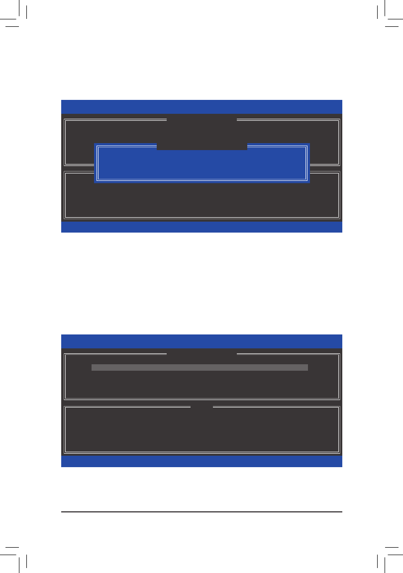
Conguring SATA Hard Drive(s)
- 68 -
Delete RAID Volume
To delete a RAID array, select Delete RAID Volume MAIN MENU in and press<Enter>. In theDELETE
VOLUME MENUsection,usetheupordownarrowkeytoselectthearraytobedeletedandpress<Delete>.
Whenpromptedtoconrmyourselection(Figure19),press<Y>toconrmor<N>toabort.
Figure 19
Acceleration Options
Thisoptionallowsyoutoviewthestatusofyouraccelerateddrive/volume(Figure20)createdusingtheIntel®
IRST utility. In case you are unable to run the Intel® IRST utility due to an application error or operating system
issue,youwillneedtoremoveaccelerationormanuallyenablesynchronization(Maximizedmodeonly)using
this option in the RAID ROM utility.
Steps:
Select in Acceleration Options MAIN MENUandpress<Enter>.
Toremovetheacceleration,selecttheaccelerateddrive/volume,press<R>,andpress<Y>toconrm.
Tosynchronizedatafromthecachedevicetotheaccelerateddrive/volume,press<S>andpress<Y>toconrm.
Figure 20
Intel(R) Rapid Storage Technology - Option ROM - 12.0.0.1783
Copyright(C) 2003-13 Intel Corporation. All Rights Reserved.
Press 's' to synchronize data from the cache device to
the Accelerated Disk/Volume
Press 'r' to remove the Disk/Volume Acceleration
WARNING: IT IS RECOMMENDED THAT YOU PERFORM A SYNCHRONIZATION
BEFORE REMOVING ACCELERATION
[hi]-Select [ESC]- Previous Menu
[ HELP ]
[ ACCELERATION OPTIONS ]
Name Type Capacity Mode Status
DISK PORT 3 Non-RAID Disk 74.5GB Enhanced In Sync
Intel(R) Rapid Storage Technology - Option ROM - 12.0.0.1783
Copyright(C) 2003-13 Intel Corporation. All Rights Reserved.
Deleting a volume will reset the disks to non-RAID.
WARNING: ALL DISK DATA WILL BE DELETED.
(This does not apply to Recovery volumes)
[hi]-Select [ESC]-Exit [DEL]-Delete Volume
[ DELETE VOLUME MENU ]
Name Level Drives Capacity Status Bootable
Volume0 RAID0(Stripe) 2 223.6GB Normal Yes
ALL DATA IN THE VOLUME WILL BE LOST!
(This does not apply to Recovery volumes)
Are you sure you want to delete "Volume0"? (Y/N) :
[ DELETE VOLUME VERIFICATION ]

- 69 -
Conguring SATA Hard Drive(s)
3-2 Installing the SATA RAID/AHCI Driver and Operating System
WiththecorrectBIOSsettings,youarereadytoinstallWindows8/7.
Figure 1
A. Installing Windows 8/7
AsWindows7alreadyincludeIntel® SATA RAID/AHCI driver, you do not need to install separate RAID/AHCI
driverduringtheWindowsinstallationprocess.Aftertheoperatingsystemisinstalled,werecommendthatyou
installallrequireddriversfromthemotherboarddriverdiskusing"XpressInstall"toensuresystemperformance
andcompatibility.ToinstallWindows8,refertothestepsbelow:
Step 1:
Copy the folder under in the driver disk to your USB thumb drive.IRST BootDrv
Step 2:
BootfromtheWindows8setupdiskandperformstandardOSinstallationsteps.Whenthescreenrequesting
you to load the driver appears, select .Browse
Step 3:
Insert the USB thumb drive and then browse to the location of the driver. The locations of the drivers are as follows:
Windows32-bit:\iRST\32Bit
Windows64-bit:\iRST\64Bit
Step 4:
WhenascreenasshowninFigure1appears,selectIntel(R) Desktop/Workstation/Server Express Chipset
SATA RAID Controller and click to load the driver and continue the OS installationNext

Conguring SATA Hard Drive(s)
- 70 -
B. Rebuilding an Array
Rebuilding is the process of restoring data to a hard drive from other drives in the array. Rebuilding applies only
to fault-tolerant arrays such as RAID 1, RAID 5 or RAID 10 arrays. The procedures below assume a new drive
isaddedtoreplaceafaileddrivetorebuildaRAID1array.(Note:Thenewdrivemusthaveequalorgreater
capacitythantheoldone.)
Turn off your computer and replace the failed hard drive with a new one. Restart your computer.
•Enabling Automatic Rebuild
Step 1:
Whenthemessage"Press<Ctrl-I>toenterCongurationUtility"appears,press<Ctrl>+<I>toentertheRAID
CongurationUtility.ThefollowingscreenappearsafteryouentertheRAIDCongurationUtility.
Step 2:
Selectthenewharddrivetoaddintothearraytoberebuiltandpress<Enter>.Thefollowingscreenappears,
indicating that an automatic rebuild will be performed after you enter the operating system. If you do not enable
automaticrebuildonthisstage,youhavetomanuallyrebuildthearrayintheoperatingsystem(seethenext
pageformoredetails).
Intel(R) Rapid Storage Technology - Option ROM - 12.0.0.1783
Copyright(C) 2003-13 Intel Corporation. All Rights Reserved.
RA
No
Ph
ID
0 ST3120026AS 3JT354CP 111.7GB Member Disk (0)
1 WDC WD800JD-22LS WD-WMAM9W736333 111.7GB Non-RAID Disk
[hi]-Select [ESC]-Exit [ENTER]-Select Menu
[ MAIN MENU ]
[ ]DEGRADED VOLUME DETECTED
[hi]-Previous/Next [ENTER]-Select [ESC]-Exit
"Degraded volume and disk available for rebuilding detected. Selecting
a disk initiates a rebuild. Rebuild completes in the operating system.
Select the port of the destination disk for rebuilding (ESC to exit):
ID Drive Model Serial # Size
1 WDC WD800JD-22LS WD-WMAM9W736333 111.7GB
Intel(R) Rapid Storage Technology - Option ROM - 12.0.0.1783
Copyright(C) 2003-13 Intel Corporation. All Rights Reserved.
RAID Volumes :
ID Name Level Strip Size Status Bootable
0 Volume0 RAID1(Mirror) N/A 111.7GB Rebuild Yes
Physical Devices :
ID Devices Model Serial # Size Type/Status(Vol ID)
0 ST3120026AS 3JT354CP 111.7GB Member Disk (0)
1 WDC WD800JD-22LS WD-WMAM9W736333 111.7GB Member Disk (0)
[hi]-Select [ESC]-Exit [ENTER]-Select Menu
[ DISK/VOLUME INFORMATION ]
Volumes with "Rebuild" status will be rebuilt within the operating system.
[ MAIN MENU ]
4. Recovery Volume Options
5. Acceleration Options
6. Exit
1. Create RAID Volume
2. Delete RAID Volume
3. Reset Disks to Non-RAID

- 71 -
Conguring SATA Hard Drive(s)
•Performing the Rebuild in the Operating System
Whileintheoperatingsystem,makesurethechipsetdriverhasbeeninstalledfromthemotherboarddriver
disk. Then launch the Intel® Rapid Storage Technology utility from the desktop.
Step 1:
Go to the menu and click Manage Rebuild to
another disk Manage Volume in .
The Status item on the left of the screen displays
the rebuild progress.
Step 2:
Select a new drive to rebuild the RAID and click
Rebuild.
Step 3:
After the RAID 1 volume rebuilding, the will Status
display as .Normal
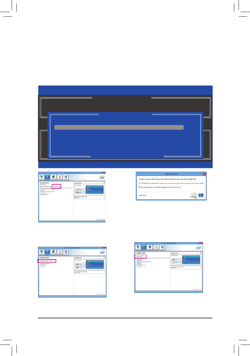
Conguring SATA Hard Drive(s)
- 72 -
Step 2:
Go to the menu of the IntelManage ® Rapid
Storage Technology utility and click Recover data
in Manage Volume.
The Status item on the left of the screen displays
the rebuild progress.
Step 3:
Click to begin the data recovery. Yes
Step 4:
After the recovery volume is completed, the Status
will display as .Normal
•Restoring the Master Drive to a Previous State (for Recovery Volume only)
WhentwoharddrivesaresettoRecoveryVolumeinUpdateonRequestmode,youcanrestorethemaster
drive data to the last backup state when needed. For example, in case the master drive detects a virus, you
can restore the recovery drive data to the master drive.
Step 1:
Select 4. Recovery Volume Options MAIN MENU in the of the Intel® RAID Conguration Utility. On the
RECOVERY VOLUMES OPTIONS Enable Only Recovery Disk menu, select to show the recovery drive in
theoperatingsystem.Followtheon-screeninstructionstocompleteandexittheRAIDCongurationUtility.
Intel(R) Rapid Storage Technology - Option ROM - 12.0.0.1783
Copyright(C) 2003-13 Intel Corporation. All Rights Reserved.
[hi]-select [ESC]-Previous Menu [ENTER]-Select
[ RECOVERY VOLUME OPTIONS ]
1. Enable Only Recovery Disk
2. Enable Only Master Disk
[ SELECT RECOVERY VOLUME ]
[hi]-Up/Down [SPACE]-Selects [ENTER]-Done
Name Level Capacity Status Bootable
`
Volume0 Recovery(OnReq) 111.7GB NeedsUpdate Yes
Select a Recovery volume to do the operation.

- 73 -
Drivers Installation
4-1 Chipset Drivers
Chapter 4 Drivers Installation
•Before installing the drivers, rst install the operating system. (The following instructions use
Windows8astheexampleoperatingsystem.)
•After installing the operating system, insert the motherboard driver disk into your optical drive. Click
on the message "Tap to choose what happens with this disc" on the top-right corner of the screen
and select "Run Run.exe."(OrgotoMyComputer,double-clicktheopticaldriveandexecutethe
Run.exeprogram.)
"XpressInstall"willautomaticallyscanyoursystemandthenlistallofthedriversthatarerecommendedto
install. You can click the Xpress Install buttonand"XpressInstall"willinstallalloftheselecteddrivers.Orclick
the arrow icon to individually install the drivers you need.
•Pleaseignorethepopupdialogbox(es)(e.g.theFound New Hardware Wizard)displayedwhen
"XpressInstall"isinstallingthedrivers.Failuretodosomayaffectthedriverinstallation.
•Some device drivers will restart your system automatically during the driver installation. After the
systemrestart,"XpressInstall"willcontinuetoinstallotherdrivers.

Drivers Installation
- 74 -
4-2 Application Software
This page displays the apps that GIGABYTE develops and some free software. You can select the apps you
want and click the icon to begin the installation.Install
4-3 Information
This page provides detailed information on the drivers on the driver disk. The page provides contact Contact
information of the GIGABYTE Taiwan headquarter. You can click the URL on this page to link to the GIGABYTE
websitetocheckmoreinformationontheGIGABYTEheadquarterorworldwidebranchofces.

- 75 -
Unique Features
5-1 BIOS Update Utilities
GIGABYTE motherboards provide two unique BIOS update tools, Q-Flash™ and @BIOS™. GIGABYTE Q-Flash
and @BIOS are easy-to-use and allow you to update the BIOS without the need to enter MS-DOS mode.
Additionally, this motherboard features the DualBIOS™ design, which enhances protection for the safety and
stability of your computer by adding one more physical BIOS chip.
What is DualBIOS™?
MotherboardsthatsupportDualBIOShavetwoBIOSonboard,amainBIOSandabackupBIOS.Normally,the
system works on the main BIOS. However, if the main BIOS is corrupted or damaged, the backup BIOS will
takeoveronthenextsystembootandcopytheBIOSletothemainBIOStoensurenormalsystemoperation.
For the sake of system safety, users cannot update the backup BIOS manually.
What is Q-Flash™?
WithQ-FlashyoucanupdatethesystemBIOSwithouthavingtoenteroperatingsystemslikeMS-DOSor
Windowrst.EmbeddedintheBIOS,theQ-Flashtoolfreesyoufromthehasslesofgoingthroughcomplicated
BIOSashingprocess.
What is @BIOS™?
@BIOSallowsyoutoupdatethesystemBIOSwhileintheWindowsenvironment.@BIOSwilldownloadthe
latestBIOSlefromthenearest@BIOSserversiteandupdatetheBIOS.
5-1-1 Updating the BIOS with the Q-Flash Utility
A. Before You Begin
1. FromGIGABYTE'swebsite,downloadthelatestcompressedBIOSupdatelethatmatchesyourmotherboard
model.
2. ExtracttheleandsavethenewBIOSle(e.g.Z87MD3H.F1)toyourUSBashdriveorharddrive.Note:
TheUSBashdriveorharddrivemustuseFAT32/16/12lesystem.
3. Restartthesystem.DuringthePOST,pressthe<End>keytoenterQ-Flash.Note:YoucanaccessQ-Flash
byeitherpressingthe<End>keyduringthePOSTorpressingthe<F8>keyinBIOSSetup.However,ifthe
BIOSupdateleissavedtoaharddriveinRAID/AHCImodeoraharddriveattachedto anindependent
SATAcontroller,usethe<End>keyduringthePOSTtoaccessQ-Flash.
BecauseBIOSashingispotentiallyrisky,pleasedoitwithcaution.InadequateBIOSashingmay
result in system malfunction.
Chapter 5 Unique Features

Unique Features
- 76 -
B. Updating the BIOS
InthemainmenuofQ-Flash,usethekeyboardormousetoselectanitemtoexecute.Whenupdatingthe
BIOS,choosethelocationwheretheBIOSleissaved.Thefollowingprocedureassumesthatyousavethe
BIOSletoaUSBashdrive.
Step 1:
1. InserttheUSBashdrivecontainingtheBIOSleintothecomputer.InthemainmenuofQ-Flash,select
Update BIOS From Drive.
Step 2:
TheprocessofthesystemreadingtheBIOSlefromtheUSBashdriveisdisplayedonthescreen.When
the message "Are you sure to update BIOS?" appears, select to begin the BIOS update. The monitor will Yes
display the update process.
Step 3:
The system will restart after the update process is complete.
2. Select USB Flash Drive.
3. SelecttheBIOSupdatele.
•The Save BIOS to DriveoptionallowsyoutosavethecurrentBIOSle.
•Q-FlashonlysupportsUSBashdriveorharddrivesusingFAT32/16/12lesystem.
•IftheBIOSupdateleissavedtoaharddriveinRAID/AHCImodeoraharddriveattachedto
anindependentSATAcontroller,usethe<End>keyduringthePOSTtoaccessQ-Flash.
MakesuretheBIOSupdatelematchesyourmotherboardmodel.
•Do not turn off or restart the system when the system is reading/updating the BIOS.
•DonotremovetheUSBashdriveorharddrivewhenthesystemisupdatingtheBIOS.
Q-Flash Utility v1.05
Model Name : Z87M-D3H
BIOS Version : F2h
BIOS Date : 03/28/2013
Flash Type/Size : Winbond 25X/Q Series 16MB
Update BIOS From Drive
Select Device
USB Flash Drive

- 77 -
Unique Features
Select to load BIOS defaultsYes
Step 4:
DuringthePOST,press<Delete>toenterBIOSSetup.SelectLoad Optimized Defaults Save & Exit on the
screenandpress<Enter>toloadBIOSdefaults.Systemwillre-detectallperipheraldevicesafteraBIOSupdate,
so we recommend that you reload BIOS defaults.
Step 5:
Select Save & Exit Setupandpress<Enter>.AndthenselectYes to save settings to CMOS and exit BIOS
Setup. The procedure is complete after the system restarts.

Unique Features
- 78 -
5-1-2 Updating the BIOS with the @BIOS Utility
A. Before You Begin
1. In Windows, close all applications and TSR
(Terminate and Stay Resident) programs. This
helps prevent unexpected failures when performing
a BIOS update.
2. If the BIOS is being updated via the Internet, ensure
the Internet connection is stable and do NOT
interrupttheInternetconnection(forexample,avoid
apowerlossorswitchingofftheInternet).Failureto
do so may result in a corrupted BIOS or a system
that is unable to start.
3. GIGABYTE product warranty does not cover any
BIOSdamageorsystemfailureresultingfromaninadequateBIOSashing.
B. Using @BIOS
•MakesurethattheBIOSletobeashedmatchesyourmotherboardmodel.UpdatingtheBIOS
withanincorrectBIOSlecouldcauseyoursystemnottoboot.
•Do not turn off the system or remove the power during the BIOS update process, or the BIOS may
corrupt and the system may not boot.
Ifthe BIOSupdatelefor yourmotherboard is notpresent onthe@BIOSserver site,please
manuallydownloadtheBIOSupdatelefromGIGABYTE'swebsiteandfollowtheinstructionsin
"Update the BIOS without Using the Internet Update Function" below.
Supported image formats include jpg, bmp, and gif.
C. After Updating the BIOS
Restart your system after updating the BIOS.
1. Update the BIOS Using the Internet Update Function:
Click Update from Server, select the @BIOS server site closest to your location and
thendownloadtheBIOSlethatmatchesyourmotherboardmodel.Followtheon-screen
instructions to complete.
2. Update the BIOS without Using the Internet Update Function:
Click Updatefromle,thenselectthelocationwhereyousavetheBIOSupdateleobtained
from the Internet or through other source. Follow the on-screen instructions to complete.
3. Save the Current BIOS File:
Click SavetoletosavethecurrentBIOSle.
4. Change the Boot-up Logo:
Click Upload new imageinFace-Wizardandyouwillbeabletochangetheboot-uplogo
withyourownpicture,creatingapersonalizedboot-upscreen.ClickBackup current image
to save the currently used boot-up logo.
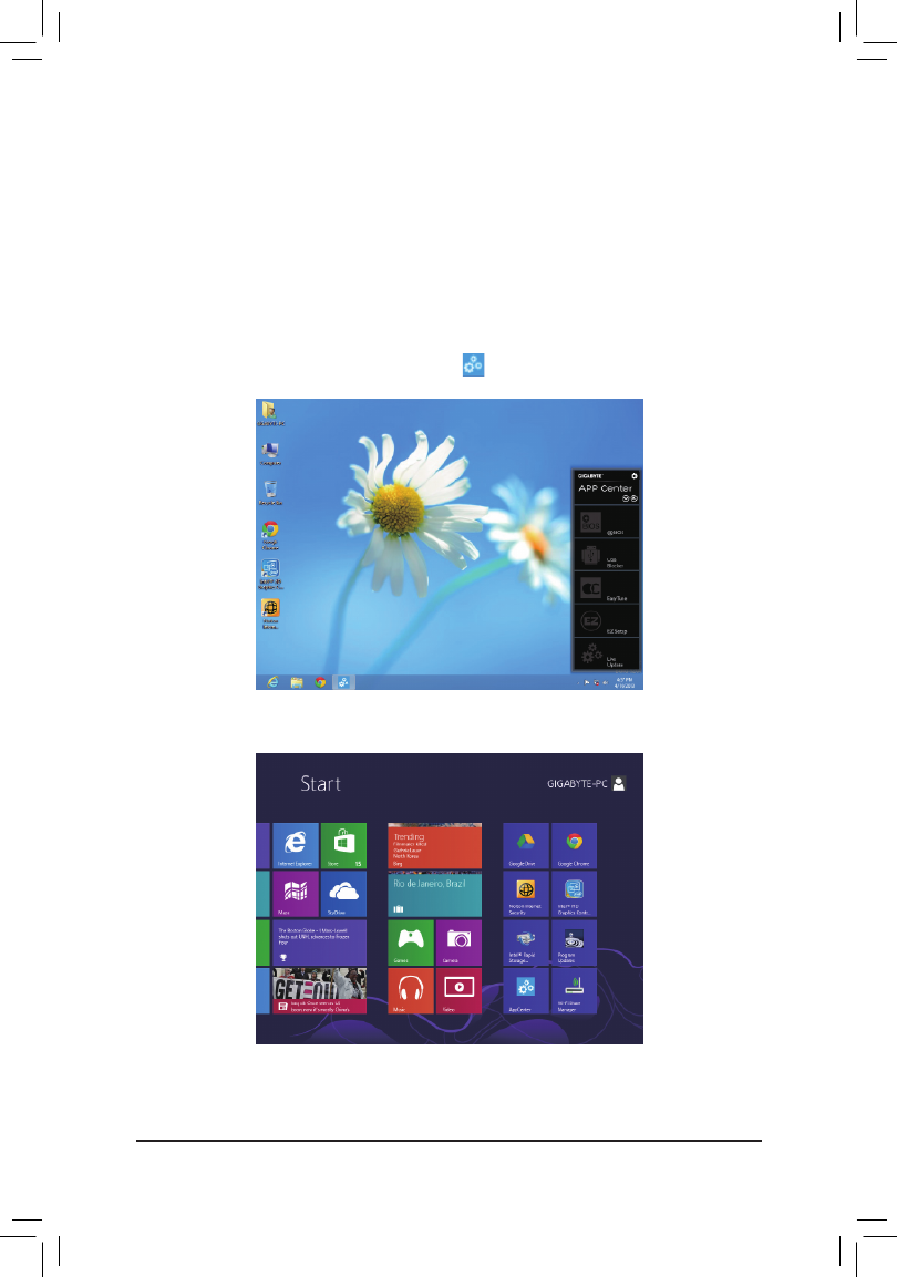
- 79 -
Unique Features
5-2 APP Center
GIGABYTE App Center gives you easy access to a wealth of GIGABYTE apps that help you get the most from
your GIGABYTE motherboard (Note).Usingasimple,unieduserinterface,GIGABYTEAppCenterallowsyou
to easily launch all GIGABYTE apps installed on your system, check related udpates online, and download the
apps, drivers, and BIOS.
Running the APP Center
Insert the motherboard driver disk. On the Autorun screen, go to Application Software\Install GIGABYTE
Utilities to install GIGABYTE App Center and the selected apps. Restart your computer after the installation
is complete. In Desktop mode, click the App Center icon inthenoticationareatolaunchtheAppCenter
utility(Figure1).Onthemainmenu,youcanselectanapptorunorclickLive Update to update an app online.
IftheAppCenterisclosed,youcanrestartitbyclickingtheAppCentericonontheStartmenu.(Figure2)
(Note) AvailableapplicationsinAPPCentermaydifferbymotherboardmodel.Supportedfunctionsofeach
applicationmayalsodifferdependingonmotherboardspecications.
Figure 2
Figure 1

Unique Features
- 80 -
5-2-1 EasyTune
GIGABYTE'sEasyTuneisasimpleandeasy-to-useinterfacethatallowsuserstone-tunetheirsystemsettings
ordooverclock/overvoltageinWindowsenvironment.Theuser-friendlyEasyTuneinterfacealsoincludestabbed
pages for CPU and memory information, letting users read their system-related information without the need
to install additional software.
The EasyTune Interface
Tabs Information
Tab Function
The tab provides information on the installed CPU and motherboard.System Information
Smart Quick Boost provides you with different levels of CPU frequency to choose to achieve
desired system performance. After making changes, be sure to restart your system for these
changestotakeeffect.TheAdvancedmenuallowsyoutochangespecicclock/frequency/
votlage settings.
The Smart Fan tab allows you to specify a Smart Fan mode. The Calibrate menu displays
the detected linear fan speed for the fans on the motherboard from the fastest to the slowest.
The Advanced menu allows you to set temperature thresholds, based on which the fan speed
can be changed linearly.
The System Alerts tab allows you to monitor hardware temperature, voltage and fan speed
and set temperature/fan speed alarm.
The tab allows you to change power phase and voltage settings.3D Power
Incorrectly doing overclock/overvoltage may result in damage to the hardware components such
as CPU, chipset, and memory and reduce the useful life of these components. Before you do the
overclock/overvoltage, make sure that you fully know each function of EasyTune, or system instability
or other unexpected results may occur.
AvailablefunctionsinEasyTunemaydifferbymotherboardmodel.Grayed-outarea(s)indicatesthat
theitemisnotcongurableorthefunctionisnotsupported.

- 81 -
Unique Features
5-2-2 EZ Setup
TheGIGABYTEEZSetuputilityincludesthefollowing'EZ'setupsapplicationsthatwilloffergreatlysimplied
install and conguration procedures: Disk Mode Switch, EZ Smart Response, EZ Rapid Start, EZ Smart
Connect,andXHD.
Disk Mode Switch
Disk Mode Switch allows you to switch the operating mode for your hard drive even after it's been installed with
an operating system. Supported operating modes include IDE, AHCI, and RAID. You can select a disk mode
and restart your computer after the selection.
•NativeUEFImodeisnotsupported.
•Be sure to reinstall the Intel® Rapid Storage Technology utility after you switch the disk mode.
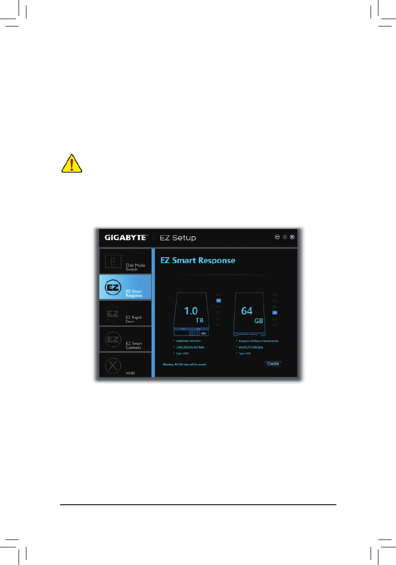
Unique Features
- 82 -
EZ Smart Response
A. System Requirements
1. An Intel® Chipset-based motherboard supporting this feature(Note1)
2. Intel® Core series processor
3. Intel® SATA controller set to RAID mode
4. Intel® Rapid Storage Technology utility installed (Note1)
5. A conventional SATA disk and an SSD(Note2)
6. Windows7withSP1/Windows8(Note3)
B. Using EZ Smart Response
Select and click . EZ Smart Response Create
To disable this function, click .Delete
IfyouhaveinstalledtheoperatingsystembeforeconguringtheSmartResponseTechnology,all
original data on the SSD will be lost once you enable RAID mode(Note4). It is recommended that you
back up the hard disk before enabling the Smart Response Technology.
(Note1) Beforestart,makesureyouhaveinstalledtheIntel®RapidStorageTechnologyutility(version11.5or
above).
(Note2) TheSSDworksasacacheoftheharddisk.Themaximumcachememorysizeis64GB.Ifyouuse
an SSD larger than 64 GB, the space beyond 64 GB can still be used for storing your data.
(Note3) TheoperatingsystemmustbeinstalledtotheSATAdisk.
(Note4) RegardlessoftheBIOSsettings,beitIDEorAHCImode,thesystemwillbeforcedintoRAIDmode.

- 83 -
Unique Features
EZ Rapid Start
A. System Requirements
1. Intel® Rapid Start Technology enabled in BIOS Setup
2. AnSSDwithsizelargerthanthetotalsystemmemory
3. Windows7withSP1/Windows8
4. AHCI/RAIDmodesupported(pleasenoteiftheSSDhasbeenassignedasamemberofaRAIDarray,it
cannot be used to set up and Intel®RapidStartstorepartition);IDEmodenotsupported(Note)
B. Using EZ Rapid Start
Select EZ Rapid Start and click Create. Then install the Intel® Rapid Start Technology utility and restart your
computer to complete.
To disable this function, click .Delete
•Thedefaultcompressedspaceisthesystemmemorysizeplus2GB.Forexample,ifthesystem
memorysizeis8GB,thedefaultcompressedspaceis8GBplus2GB,sotheSSDcapacitywill
decrease by 10 GB. If EZ Rapid Start is disabled, the decreased 10 GB will be returned to the SSD.
•Ifyouwanttoupgradeyoursystemmemory,disableEZRapidStartrstandre-installittoensure
it can work normally.
(Note) IfthemotherboardChipsetsupportsRAID,EZRapidStartwillforcetheIntel® SATA controllers into
RAID mode. If not, the Intel® SATA controllers will be forced into AHCI mode.
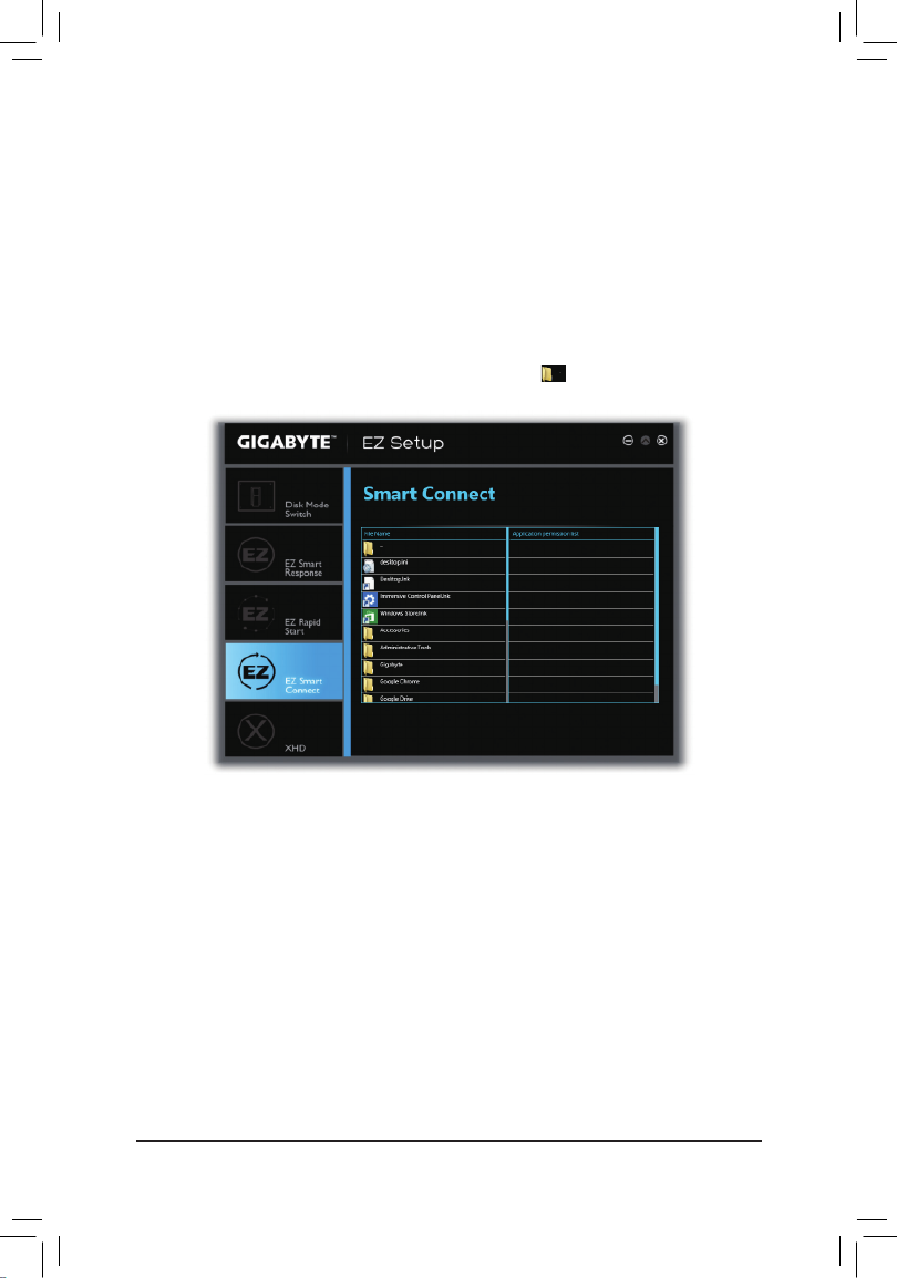
Unique Features
- 84 -
EZ Smart Connect
A. System Requirements
1. Intel® Smart Connect Technology enabled in BIOS Setup
2. Windows7withSP1/Windows8
3. Intel® Smart Connect Technology utility installed
4. Properly-working network connection
5. ProgramsaddedtotheWhiteListmustbeturnedon(Note)
B. Using EZ Smart Connect
Select EZ Smart Connect File Name. Under , select the apps to be auto-updated by Smart Connect. Double-
click the app to add it to the Application permission list.(Double-click toreturntothepreviousdirectory.)
(Note) ThisfeatureworksbestwithprogramsdesignedtoworkautomaticallywiththeInternettoobtaintheir
data such as Outlook®,WindowsLive™ Mail, and Seesmic®.
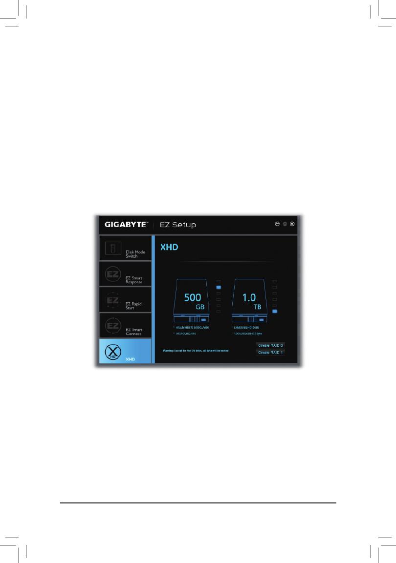
- 85 -
Unique Features
XHD
WithGIGABYTEXHD(Note1),userscanquicklycongureaRAID-readysystemforRAID0orRAID1whena
newSATAdriveisadded.Allwithasimpleclickofabutton,XHDhelpstoenhanceyourharddriveread/write
performancewithouttheneedforcomplexandtime-consumingcongurations..
A. System Requirements
1. An Intel® Chipset motherboard supporting RAID
2. Intel® SATA controllers set to RAID mode
3. Intel® Rapid Storage Technology utility installed
4. Windows7withSP1/Windows8
5. Intel® SATA controller driver installed
B. Using XHD
Select and click or based on your need. XHD Create RAID 0 Create RAID 1 (Note2)
(Note1) TheXHDutilityonlysupportstheSATAconnectorscontrolledbytheIntel® Chipset.
(Note2) Exceptfortheoperatingsystemdrive,alldataonotherharddrivewillbedeleted.Backupyourdata
beforeusingtheXHDutility.

Unique Features
- 86 -
5-2-3 USB Blocker
GIGABYTE USB Blocker provides you with an easy-to-use interface that allows you to block certain USB device
types on your PC. Devices classes that are blocked will be ignored by the operating system.
The USB Blocker Interface
Using USB Blocker
Select the class of USB device that you would like to block or unblocked. Double left-click to change the Blocked
or status and click . Then enter your password and click to complete. Unblocked OK OK

Appendix
- 88 -
Step 2:
Connect an audio device to an audio jack. The The current
connected device is dialog box appears. Select the device
according to the type of device you connect. Then click OK.
Step 3:
On the screen, click the Speakers SpeakerConguration
tab. In the list, select Speaker Configuration Stereo,
Quadraphonic, 5.1 Speaker 7.1 Speaker, or according to
thetypeofspeakercongurationyouwishtosetup.Then
the speaker setup is completed.
If your chassis provides an AC'97 front panel audio module,
to activate the AC'97 functionality, click the tool icon on the
SpeakerConguration tab. On the Connector Settings
dialog box, select the Disable front panel jack detection
check box. Click to complete.OK
Click Device advanced settings on the top right corner
on the tab to open the Speaker Conguration Device
advanced settings Mute the rear dialog box. Select the
output device, when a front headphone plugged in check
box. Click to complete.OK
B.ConguringSoundEffect
YoumaycongureanaudioenvironmentontheSound Effects tab.
C. Activating an AC'97 Front Panel Audio Module
D. Muting the Back Panel Audio (For HD Audio Only)

- 89 -
Appendix
6-1-2 ConguringS/PDIFOut
ConguringS/PDIFOut:
On the screen, click the tab and then select the sample rate and bit depth. Digital Output Default Format
Click OK to complete.
The S/PDIF Out jack can transmit audio signals to an external decoder for decoding to get the best audio quality.

Appendix
- 90 -
6-1-3 ConguringMicrophoneRecording
Step 1:
After installing the audio driver, the HD Audio Manager
icon willappearinthenoticationarea.Double-click
the icon to access the .HD Audio Manager
Step 2:
ConnectyourmicrophonetotheMicinjack(pink)onthe
backpanelortheMicinjack(pink)onthefrontpanel.
Thencongurethejackformicrophonefunctionality.
Note:Themicrophonefunctionsonthefrontpaneland
back panel cannot be used at the same time.
Step 3:
Go to the screen. Do not mute the recording Microphone
volume, or you'll not be able to record the sound. To hear
the sound being recorded during the recording process,
do not mute the playback volume. It is recommended that
you set the volumes at a middle level.
Step 4:
To raise the recording and playback volume for the
microphone, click the icon Microphone Boost on
the right of the Recording Volume slider and set the
Microphone Boost level.

- 91 -
Appendix
Step 5:
To open the Sounder Recorder, move the mouse cursor
to the bottom left corner of the screen, click the Start
icon to switch to the Startscreen(orpresstheWindows
buttononthekeyboard).Right-clickonthescreenand
click the icon on the bottom right corner of All apps
the screen to access the screenApps
Step 1:
Locate the iconinthenoticationareaandright-click
on this icon. Select .Recording Devices
* Enabling Stereo Mix
If the HD Audio Manager does not display the recording device you wish to use, refer to the steps below. The
followingstepsexplainhowtoenableStereoMix(whichmaybeneededwhenyouwanttorecordsoundfrom
yourcomputer).
Step 6:
On this screen, click for audio recording. Sound Recorder

Appendix
- 92 -
6-1-4 Using the Sound Recorder
A. Recording Sound
1. Makesureyouhaveconnectedthesoundinputdevice(e.g.microphone)tothecomputer.
2. To record the audio, click the button .Start Recording
3. To stop recording audio, click the button .Stop Recording
Besuretosavetherecordedaudioleuponcompletion.
B. Playing the Recorded Sound
Youcanplayyourrecordinginadigitalmediaplayerprogramthatsupportsyouraudioleformat.
Step 4:
NowyoucanaccesstheHD Audio Managertocongure
Stereo Mix Sound Recorder and use to record the
sound.
Step 2:
On the tab, right-click on an empty space and Recording
select .Show Disabled Devices
Step 3:
WhentheStereo Mix item appears, right-click on this
item and select . Then set it as the default device.Enable
Termékspecifikációk
| Márka: | Gigabyte |
| Kategória: | alaplap |
| Modell: | GA-Z87M-D3H |
Szüksége van segítségre?
Ha segítségre van szüksége Gigabyte GA-Z87M-D3H, tegyen fel kérdést alább, és más felhasználók válaszolnak Önnek
Útmutatók alaplap Gigabyte

14 Január 2025
13 Január 2025
12 Január 2025
12 Január 2025
12 Január 2025
9 Január 2025
9 Január 2025
9 Január 2025
9 Január 2025
9 Január 2025
Útmutatók alaplap
- alaplap Sharkoon
- alaplap Asus
- alaplap Supermicro
- alaplap Biostar
- alaplap Asrock
- alaplap MSI
- alaplap NZXT
- alaplap ECS
- alaplap Evga
- alaplap Intel
- alaplap Foxconn
- alaplap Advantech
- alaplap Elitegroup
- alaplap EPoX
Legújabb útmutatók alaplap

9 Április 2025
9 Április 2025
3 Április 2025
3 Április 2025
3 Április 2025
3 Április 2025
2 Április 2025
2 Április 2025

31 Március 2025
27 Március 2025