Használati útmutató Gigabyte GA-X79S-UP5-WIFI
Olvassa el alább 📖 a magyar nyelvű használati útmutatót Gigabyte GA-X79S-UP5-WIFI (112 oldal) a alaplap kategóriában. Ezt az útmutatót 8 ember találta hasznosnak és 2 felhasználó értékelte átlagosan 4.5 csillagra
Oldal 1/112

GA-X79S-UP5-WIFI
GA-X79S-UP5
User's Manual
Rev. 1002
12ME-X79SUP5-1002R

Motherboard
GA-X79S-UP5-WIFI
GA-X79S-UP5
Aug. 3, 2012
Aug. 3, 2012
Motherboard
GA-X79S-UP5-WIFI
GA-X79S-UP5

Copyright
© 2012 GIGA-BYTE TECHNOLOGY CO., LTD. All rights reserved.
The trademarks mentioned in this manual are legally registered to their respective owners.
Disclaimer
Information in this manual is protected by copyright laws and is the property of GIGABYTE.
Changes to the specications and features in this manual may be made by GIGABYTE
without prior notice. No part of this manual may be reproduced, copied, translated, transmit-
ted, orpublished in any form or by any means without GIGABYTE's prior written permission.
Documentation Classications
In order to assist in the use of this product, GIGABYTE provides the following types of
documentations:
For quick set-up of the product, read the Quick Installation Guide included with the product.
For detailed product information, carefully read the User's Manual.
For product-related information, check on our website at: http://www.gigabyte.com
Identifying Your Motherboard Revision
The revision number on your motherboard looks like this: "REV: X.X." For example, "REV:
1.0" means the revision of the motherboard is 1.0. Check your motherboard revision before
updating motherboard BIOS, drivers, or when looking for technical information.
Example:

- 4 -
Table of Contents
Box Contents ...................................................................................................................6
Optional Items .................................................................................................................6
GA-X79S-UP5-WIFI/GA-X79S-UP5 Motherboard Layout..............................................7
GA-X79S-UP5-WIFI/GA-X79S-UP5 Motherboard Block Diagram .................................8
Chapter 1 Hardware Installation 9 .....................................................................................
1-1 Installation Precautions ................................................................................... 9
1-2 ProductSpecications ................................................................................... 10
1-3 Installing the CPU and CPU Cooler............................................................... 13
1-3-1 Installing the CPU ..................................................................................................13
1-3-2 Installing the CPU Cooler ......................................................................................15
1-4 Installing the Memory .................................................................................... 16
1-4-1 4ChannelMemoryConguration..........................................................................16
1-4-2 Installing a Memory ................................................................................................17
1-5 Installing an Expansion Card ......................................................................... 18
1-6 SettingupAMDCrossFireX™/NVIDIASLIConguration ............................ 19
1-7 Back Panel Connectors ................................................................................. 20
1-8 Onboard Buttons............................................................................................ 22
1-9 Internal Connectors ....................................................................................... 23
Chapter 2 BIOS Setup ..................................................................................................33
2-1 Startup Screen ............................................................................................... 34
2-2 The Main Menu .............................................................................................. 35
2-3 M.I.T. .............................................................................................................. 37
2-4 System ........................................................................................................... 49
2-5 BIOS Features ............................................................................................... 50
2-6 Peripherals ..................................................................................................... 52
2-7 Power Management ....................................................................................... 55
2-8 Save & Exit .................................................................................................... 57
Chapter 3 Drivers Installation .......................................................................................59
3-1 Installing Chipset Drivers ............................................................................... 59
3-2 Application Software ......................................................................................60
3-3 Technical Manuals ......................................................................................... 60
3-4 Contact........................................................................................................... 61
3-5 System ........................................................................................................... 61

- 5 -
3-6 Download Center ........................................................................................... 62
3-7 New Program ................................................................................................. 62
Chapter 4 Unique Features ...........................................................................................63
4-1 BIOS Update Utilities ..................................................................................... 63
4-1-1 Updating the BIOS with the Q-Flash Utility .......................................................... 63
4-1-2 Updating the BIOS with the @BIOS Utility ........................................................... 66
4-2 EasyTune 6 67 ....................................................................................................
4-3 Q-Share ......................................................................................................... 68
Chapter 5 Appendix ......................................................................................................69
5-1 ConguringSATAHardDrive(s) .................................................................... 69
5-1-1 ConguringIntelC606SATAControllers ............................................................. 69
5-1-2 ConguringMarvell88SE9172SATAControllers .................................................75
5-1-3 Installing the SATA RAID/AHCI Driver and Operating System .............................81
5-2 ConguringSASHardDrive(s) ...................................................................... 86
5-2-1 ConguringSASControllers ................................................................................ 86
5-2-2 Installing the SAS RAID Driver and Operating System ........................................92
5-3 ConguringAudioInputandOutput .............................................................. 95
5-3-1 Conguring2/4/5.1/7.1-ChannelAudio ................................................................. 95
5-3-2 ConguringS/PDIFOut .........................................................................................97
5-3-3 ConguringMicrophoneRecording ...................................................................... 98
5-3-4 Using the Sound Recorder ................................................................................. 100
5-4 Troubleshooting ........................................................................................... 101
5-4-1 Frequently Asked Questions ...............................................................................101
5-4-2 Troubleshooting Procedure .................................................................................102
5-5 Regulatory Statements ................................................................................ 104
- 7 -
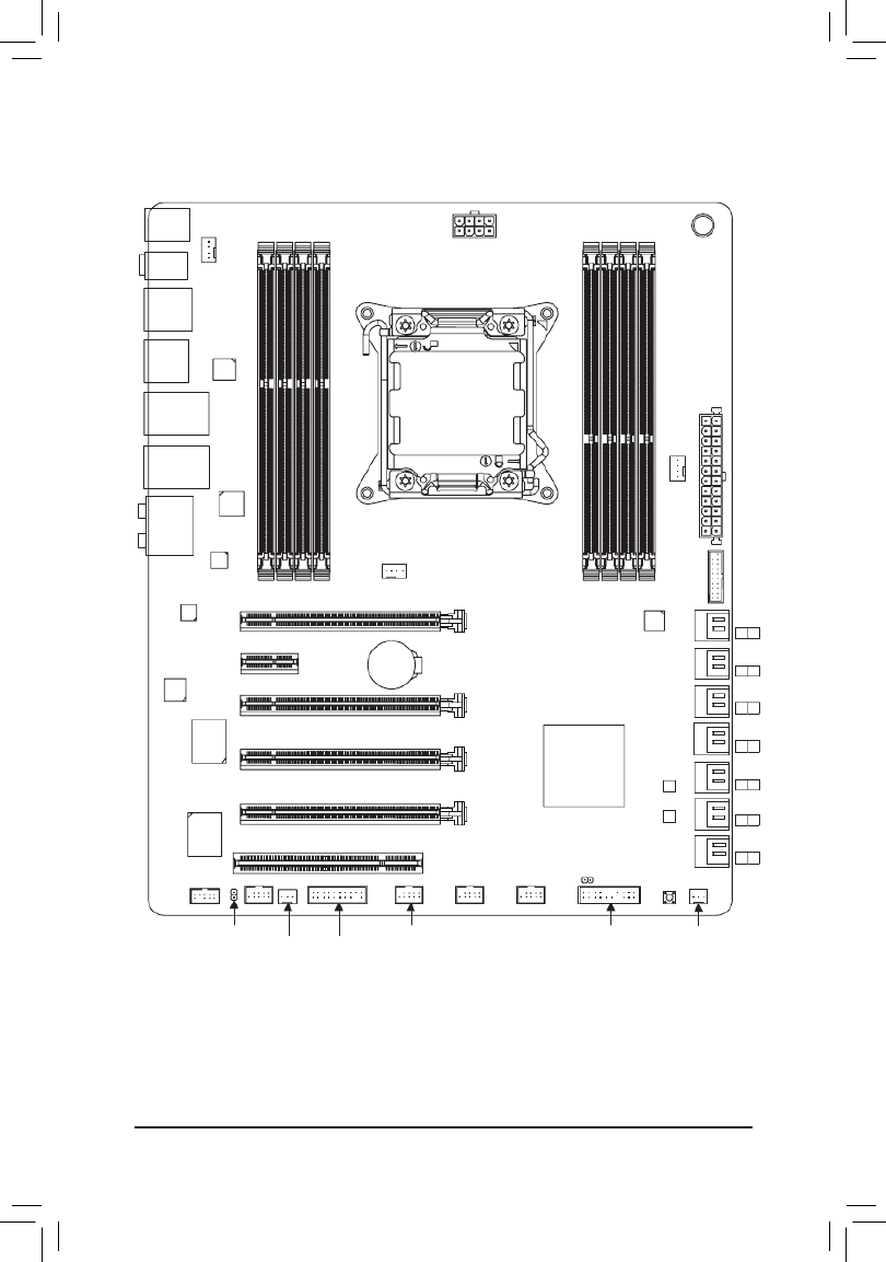
GA-X79S-UP5-WIFI/GA-X79S-UP5 Motherboard Layout
KB_MS_USB
CPU_FAN
ATX_12V_2X4
ATX
F_AUDIO
B_BIOS
PCIEX8
BAT
F_PANEL
Intel®
C606
CLR_CMOS
M_BIOS
PCIEX16_1
SPDIF_O
F_USB2
GA-X79S-UP5-WIFI
GA-X79S-UP5
HS
PCI
F_USB30
PCIEX1
TPM
F_USB1
F_USB3
SYS_FAN1
SYS_FAN4 SYS_FAN3
SAS2
CODEC
7
6
PW_SW
USB_1394_ESATA
USB_ESATA
USB30_LAN2
AUDIO
USB30_LAN1
SYS_FAN2
Marvell
88SE9172
DDR3_4
DDR3_3
DDR3_2
DDR3_1
DDR3_5
DDR3_6
DDR3_7
DDR3_8
LGA2011
PCIEX4
VIA
VT6308
PCIEX16_2
F_1394 RST_SW
SAS2
5
4
SAS2
3
2
SAS2
1
0
SATA2
5
4
SATA2
3
2
SATA3
1
0
Fresco
FL1009
VIA
VL800
Re a l t e k
GbE LAN
Intel
GbE LAN
iTE
Super I/O

- 8 -
GA-X79S-UP5-WIFI/GA-X79S-UP5 Motherboard Block Diagram
For detailed product information/limitation(s), refer to "1-2 Product Specications."
Center/Subwoofer Speaker Out
Line Out
MIC
Line In
S/PDIF Out
Surround Speaker Out
PS/2 KB/Mouse
LGA2011
CPU
CPU CLK+/- (100 MHz)
Dual BIOS
12 USB 2.0/1.1
DDR3 2133/1866/1600/1333/1066 MHz
LPC Bus
x1
2 USB 3.0/2.0
PCI Express Bus
PCI Express Bus
PCIe CLK
(100 MHz)
1 PCI Express x1
x1
1 PCI
PCI Bus
PCI CLK
(33 MHz)
CODEC
2 SATA 6Gb/s
LAN
RJ45
x1
Marvell
88SE9172
Intel GbE
LAN phy
VIA VT6308
2 IEEE 1394a
4 Channel Memory
2 SATA 6Gb/s
4 SATA 3Gb/s
x1
PCI Express Bus
PCIe CLK
(100 MHz)
Switch
x16
x16
1 PCI Express x16 2 PCI Express x8
or
x16
1 PCI Express x16
LAN
RJ45
Realtek GbE
LAN phy
x1
x1
4 USB 3.0/2.0
VIA
VL800
Fresco
FL1009
iTE
Super I/O
8 SAS 3Gb/s
Intel® C606
x4
1 PCI Express x4
DMI 2.0 PCIe p8-x4 Uplink

- 9 -
Hardware Installation
1-1 Installation Precautions
The motherboard contains numerous delicate electronic circuits and components which can become
damaged as a result of electrostatic discharge (ESD). Prior to installation, carefully read the user's
manual and follow these procedures:
•Prior to installation, make sure the chassis is suitable for the motherboard.
•Prior to installation, do not remove or break motherboard S/N (Serial Number) sticker or
warranty sticker provided by your dealer. These stickers are required for warranty validation.
•Always remove the AC power by unplugging the power cord from the power outlet before
installing or removing the motherboard or other hardware components.
•When connecting hardware components to the internal connectors on the motherboard, make
sure they are connected tightly and securely.
•When handling the motherboard, avoid touching any metal leads or connectors.
•It is best to wear an electrostatic discharge (ESD) wrist strap when handling electronic
components such as a motherboard, CPU or memory. If you do not have an ESD wrist strap,
keep your hands dry and rst touch a metal object to eliminate static electricity.
•Prior to installing the motherboard, please have it on top of an antistatic pad or within an
electrostatic shielding container.
•Before unplugging the power supply cable from the motherboard, make sure the power supply
has been turned off.
•Before turning on the power, make sure the power supply voltage has been set according to
the local voltage standard.
•Before using the product, please verify that all cables and power connectors of your hardware
components are connected.
•To prevent damage to the motherboard, do not allow screws to come in contact with the
motherboard circuit or its components.
•Make sure there are no leftover screws or metal components placed on the motherboard or
within the computer casing.
•Do not place the computer system on an uneven surface.
•Do not place the computer system in a high-temperature environment.
•Turning on the computer power during the installation process can lead to damage to system
components as well as physical harm to the user.
•If you are uncertain about any installation steps or have a problem related to the use of the
product, please consult a certied computer technician.
Chapter 1 Hardware Installation

- 11 -
Hardware Installation
Storage Interface Marvell 88SE9172 chip:
- 2 x eSATA 6Gb/s connectors (including 1 eSATA/USB Combo) on the back
panel supporting up to 2 SATA 6Gb/s devices
- Support for RAID 0 and RAID 1
USB Chipset:
- Up to 12 USB 2.0/1.1 ports (6 ports on the back panel, including 1 eSATA/
USB Combo, 6 ports available through the internal USB headers)
VIA VL800 chip:
- Up to 4 USB 3.0/2.0 ports on the back panel
* Due to a Windows 7 limitation, please connect your USB device(s) to the USB 2.0/1.1
port(s) before the VIA USB 3.0 controller driver is installed.
Fresco FL1009 chip:
- Up to 2 USB 3.0/2.0 ports (available through the internal USB header)
IEEE 1394 VIA VT6308 chip:
- Up to 2 IEEE 1394a ports (1 port on the back panel, 1 port available through
the internal IEEE 1394a header)
Internal
Connectors
1 x 24-pin ATX main power connector
1 x 8-pin ATX 12V power connector
2 x SATA 6Gb/s connectors
4 x SATA 3Gb/s connectors
8 x SAS 3Gb/s connectors
1 x CPU fan header
4 x system fan headers
1 x front panel header
1 x front panel audio header
1 x S/PDIF Out header
1 x USB 3.0/2.0 header
3 x USB 2.0/1.1 headers
1 x IEEE 1394a port
1 x Clear CMOS jumper
1 x Trusted Platform Module (TPM) header
1 x power button
1 x reset button
Back Panel
Connectors
1 x PS/2 keyboard/mouse port
1 x CPU overclocking button
1 x BIOS switch button
1 x Clear CMOS button
1 x IEEE 1394a port
4 x USB 3.0/2.0 ports
5 x USB 2.0/1.1 ports
1 x eSATA/USB Combo connector
1 x eSATA 6Gb/s connector
2 x RJ-45 ports
1 x optical S/PDIF Out connector
5 x audio jacks (Center/Subwoofer Speaker Out, Rear Speaker Out, Line In,
Line Out, Mic In)

- 12 -
Hardware Installation
I/O Controller iTE I/O Controller Chip
Hardware
Monitor
System voltage detection
CPU/System temperature detection
CPU/System fan speed detection
CPU overheating warning
CPU/System fan fail warning
CPU/System fan speed control
* Whether the CPU/system fan speed control function is supported will depend on the
CPU/system cooler you install.
BIOS 2 x 64 Mbit ashfl
Use of licensed AMI EFI BIOS
Support for DualBIOS™
PnP 1.0a, DMI 2.0, SM BIOS 2.6, ACPI 2.0a
Unique Features Support for @BIOS
Support for Q-Flash
Support for Xpress Install
Support for EasyTune
* Available functions in EasyTune may differ by motherboard model.
Support for ON/OFF Charge
Support for 3TB+ Unlock
Support for Q-Share
Support for 3D Power
Bundled
Software Norton Internet Security (OEM version)
Operating
System Support for Microsoft® Windows 7/Vista
Form Factor E-ATX Form Factor; 30.5cm x 26.4cm
* GIGABYTE reserves the right to make any changes to the product speci cations and product-related information without fi
prior notice.
* Please visit GIGABYTE's website to check the supported operating system(s) for the software listed in the "Unique
Features" and "Bundled Software" columns.

- 17 -
Hardware Installation
1-4-2 Installing a Memory
Before installing a memory module, make sure to turn off the computer and unplug the power
cord from the power outlet to prevent damage to the memory module. DDR3 and DDR2 DIMMs are
not compatible to each other or DDR DIMMs. Be sure to install DDR3 DIMMs on this motherboard.
Notch
DDR3 DIMM
A DDR3 memory module has a notch, so it can only t in one direction. Follow the steps below to correctly install
your memory modules in the memory sockets.
Step 1:
Note the orientation of the memory module. Spread the retaining clips
at both ends of the memory socket. Place the memory module on the
socket. As indicated in the picture on the left, place your ngers on
the top edge of the memory, push down on the memory and insert it
vertically into the memory socket.
Step 2:
The clips at both ends of the socket will snap into place when the
memory module is securely inserted.
Due to CPU limitations, read the following guidelines before installing the memory in Dual Channel mode.
1. For optimum performance, when enabling Dual Channel mode with two memory modules, we
recommend that you install them in the DDR3_1 and DDR3_2 sockets.
2. When installing the memory, make sure to begin with the rst socket of each channel, such as DDR3_1,
DDR3_2, DDR3_3, and DDR3_4.

- 18 -
Hardware Installation
1-5 Installing an Expansion Card
Read the following guidelines before you begin to install an expansion card:
•Make sure the motherboard supports the expansion card. Carefully read the manual that came
with your expansion card.
•Always turn off the computer and unplug the power cord from the power outlet before installing an
expansion card to prevent hardware damage.
Follow the steps below to correctly install your expansion card in the expansion slot.
1. Locate an expansion slot that supports your card. Remove the metal slot cover from the chassis back panel.
2. Align the card with the slot, and press down on the card until it is fully seated in the slot.
3. Make sure the metal contacts on the card are completely inserted into the slot.
4. Secure the card's metal bracket to the chassis back panel with a screw.
5. After installing all expansion cards, replace the chassis cover(s).
6. Turn on your computer. If necessary, go to BIOS Setup to make any required BIOS changes for your
expansion card(s).
7. Install the driver provided with the expansion card in your operating system.
Example: Installing and Removing a PCI Express Graphics Card:
•Installing a Graphics Card:
Gently push down on the top edge of the card until
it is fully inserted into the PCI Express slot. Make
sure the card is securely seated in the slot and
does not rock.
PCI Express p18-x1 Slot
PCI Express x16 Slot
PCI Slot
•Removing the Card:
Gently push back on the lever on the slot and then lift the card straight out from
the slot.

- 20 -
Hardware Installation
1-7 Back Panel Connectors
•When removing the cable connected to a back panel connector, rst remove the cable from your
device and then remove it from the motherboard.
•When removing the cable, pull it straight out from the connector. Do not rock it side to side to prevent
an electrical short inside the cable connector.
USB 2.0/1.1 Port
The USB port supports the USB 2.0/1.1 specication. Use this port for USB devices such as a USB
keyboard/mouse, USB printer, USB ash drive and etc.
PS/2 Keyboard/Mouse Port
Use this port to connect a PS/2 mouse or keyboard.
CPU Overclocking Button
Press this button to overclock your CPU. To return to the defaults, press this button again.
BIOS Switch Button
The button allows users to easily select a different BIOS for boot up or overclocking, helping to reduce
BIOS failure during overclocking. Press the button to switch between the main BIOS and backup BIOS.
The green LED indicates the main BIOS is active and the blue LED indicates the backup BIOS is active.
Clear CMOS Button
Use this button to clear the CMOS values (e.g. date information and BIOS congurations) and reset the
CMOS values to factory defaults when needed.
IEEE 1394a Port
The IEEE 1394 port supports the IEEE 1394a specication, featuring high speed, high bandwidth and
hotplug capabilities. Use this port for an IEEE 1394a device.
eSATA/USB Combo Connector
This connector supports SATA 6Gb/s and USB 2.0/1.1 specication. Use the port to connect an external
SATA device or a SATA port multiplier. The Marvell 88SE9172 chip supports RAID function. Refer to Chapter
5, "Conguring SATA Hard Drive(s)," for instructions on conguring a RAID array. Or use this port for USB
devices such as a USB keyboard/mouse, USB printer, USB ash drive and etc.
eSATA6Gb/sConnector
This connector supports SATA 6Gb/s specication. Use the port to connect an external SATA device or a
SATA port multiplier. The Marvell 88SE9172 chip supports RAID function. Refer to Chapter 5, "Conguring
SATA Hard Drive(s)," for instructions on conguring a RAID array.
O.C.
Termékspecifikációk
| Márka: | Gigabyte |
| Kategória: | alaplap |
| Modell: | GA-X79S-UP5-WIFI |
Szüksége van segítségre?
Ha segítségre van szüksége Gigabyte GA-X79S-UP5-WIFI, tegyen fel kérdést alább, és más felhasználók válaszolnak Önnek
Útmutatók alaplap Gigabyte

14 Január 2025
13 Január 2025
12 Január 2025
12 Január 2025
12 Január 2025
9 Január 2025
9 Január 2025
9 Január 2025
9 Január 2025
9 Január 2025
Útmutatók alaplap
- alaplap Sharkoon
- alaplap Asus
- alaplap Supermicro
- alaplap Biostar
- alaplap Asrock
- alaplap MSI
- alaplap NZXT
- alaplap ECS
- alaplap Evga
- alaplap Intel
- alaplap Foxconn
- alaplap Advantech
- alaplap Elitegroup
- alaplap EPoX
Legújabb útmutatók alaplap

9 Április 2025
9 Április 2025
3 Április 2025
3 Április 2025
3 Április 2025
3 Április 2025
2 Április 2025
2 Április 2025

31 Március 2025
27 Március 2025