Használati útmutató Gigabyte GA-X58A-UD9
Olvassa el alább 📖 a magyar nyelvű használati útmutatót Gigabyte GA-X58A-UD9 (152 oldal) a alaplap kategóriában. Ezt az útmutatót 8 ember találta hasznosnak és 2 felhasználó értékelte átlagosan 4.5 csillagra
Oldal 1/152

GA-X58A-UD9
LGA1366 socket motherboard for Intel® Core™ i7 processor family
User's Manual
Rev. 1001
12ME-X58AUD9-1001R

Motherboard
GA-X58A-UD9
Apr. 12, 2010
Apr. 12, 2010
Motherboard
GA-X58A-UD9

Copyright
© 2010 GIGA-BYTE TECHNOLOGY CO., LTD. All rights reserved.
The trademarks mentioned in this manual are legally registered to their respective owners.
Disclaimer
Information in this manual is protected by copyright laws and is the property of GIGABYTE.
Changes to the specifications and features in this manual may be made by GIGABYTE
without prior notice. No part of this manual may be reproduced, copied, translated, transmitted,
or published in any form or by any means without GIGABYTE's prior written permission.
Documentation Classications
In order to assist in the use of this product, GIGABYTE provides the following types of documentations:
For quick set-up of the product, read the Quick Installation Guide included with the product.
For detailed product information, carefully read the User's Manual.
For instructions on how to use GIGABYTE's unique features, read or download the information
on/from the Support&Downloads\Motherboard\Technology Guide page on our website.
For product-related information, check on our website at:
http://www.gigabyte.com.tw
Identifying Your Motherboard Revision
The revision number on your motherboard looks like this: "REV: X.X." For example, "REV: 1.0"
means the revision of the motherboard is 1.0. Check your motherboard revision before updating
motherboard BIOS, drivers, or when looking for technical information.
Example:

- 5 -
Chapter 3 Drivers Installation ........................................................................................69
3-1 Installing Chipset Drivers ............................................................................... 69
3-2 Application Software ...................................................................................... 70
3-3 Technical Manuals .......................................................................................... 70
3-4 Contact ........................................................................................................... 71
3-5 System ........................................................................................................... 71
3-6 Download Center ........................................................................................... 72
3-7 New Utilities ................................................................................................... 72
Chapter 4 Unique Features ...........................................................................................73
4-1 Xpress Recovery2 .......................................................................................... 73
4-2 BIOS Update Utilities ..................................................................................... 76
4-2-1 Updating the BIOS with the Q-Flash Utility .............................................................76
4-2-2 Updating the BIOS with the @BIOS Utility .............................................................79
4-3 EasyTune 6 .................................................................................................... 80
4-4 Dynamic Energy Saver™ 2 .............................................................................. 81
4-5 Q-Share .......................................................................................................... 83
4-6 Smart 6™ ....................................................................................................... 84
4-7 Auto Green ..................................................................................................... 87
4-8 eXtreme Hard Drive (X.H.D) ......................................................................... 88
4-9 Teaming ..............................................................................................89
Chapter 5 Appendix ......................................................................................................91
5-1 ConguringSATAHardDrive(s) ..................................................................... 91
5-1-1 ConguringIntelICH10RSATAControllers ...........................................................91
5-1-2 ConguringJMicronJMB362/GIGABYTESATA2SATAController ........................99
5-1-3 ConguringMarvell9128SATAController ...........................................................105
5-1-4 Making a SATA RAID/AHCI Driver Diskette .......................................................... 011
5-1-5 Installing the SATA RAID/AHCI Driver and Operating System ............................. 211
5-2 ConguringAudioInputandOutput ............................................................. 125
5-2-1 Conguring2/4/5.1/7.1-ChannelAudio .................................................................125
5-2-2 ConguringS/PDIFIn/Out ....................................................................................127
5-2-3 Enabling the Dolby Home Theater Function ........................................................129
5-2-4 ConguringMicrophoneRecording ......................................................................130
5-2-5 Using the Sound Recorder ...................................................................................132
5-3 Troubleshooting............................................................................................ 133
5-3-1 Frequently Asked Questions ................................................................................133
5-3-2 Troubleshooting Procedure ..................................................................................134
5-4 POST Error Code ......................................................................................... 136
5-5 Regulatory Statements ................................................................................. 140

- 6 -
Box Contents
GA-X58A-UD9 motherboard
Motherboard driver disk
User's Manual
Quick Installation Guide
One IDE cable
Four SATA 3Gb/s cables
One SATA bracket
I/O Shield
One Hybrid Silent-Pipe module kit
One 2-Way SLI bridge connector
One 3-Way SLI bridge connector
One 4-Way SLI bridge connector
Two 2-Way CrossFireX bridge connectors
Optional Items
Floppy disk drive cable (Part No. 12CF1-1FD001-7*R)
2-port USB 2.0 bracket (Part No. 12CR1-1UB030-5*R)
2-port IEEE 1394a bracket (Part No. 12CF1-1IE008-0*R)
2-port SATA power cable (Part No. 12CF1-2SERPW-0*R)
S/PDIF In cable (Part No. 12CR1-1SPDIN-0*R)
• The box contents above are for reference only and the actual items shall depend on the product package you obtain.
The box contents are subject to change without notice.
• The motherboard image is for reference only.

- 7 -
GA-X58A-UD9 Motherboard Layout
(Note) For error code information, please refer to Chapter 5.
KB_MS
CPU_FAN
LGA1366
ATX
GA-X58A-UD9
CD_IN
F_AUDIO
AUDIO
B_BIOS
PCIEX16_2
IDE
SPDIF_I
DDR3_1
DDR3_3
DDR3_2
DDR3_5
BAT
F_PANEL
F_USB3
IT8720
ATX_12V_2X
Intel®
X58
Intel®
ICH10R
FDD
SATA2_1
SATA2_3
SATA2_5
GSATA3_7
SATA2_0
SATA2_2
SATA2_4
GSATA3_6
USB_LAN
CODEC
PWR_FAN
NB_FAN
SYS_FAN1
M_BIOS
RTL8111E
R_SPDIF
USB_1394_ESATA_2
USB30_LAN
PCIEX16_1
PCIE_12V_1
SPDIF_O
F_USB2
F_1394
SYS_FAN2
TSB43AB23
PHASE LED
SYS_FAN3
CPU TEMP L1/2
CPU Voltage L1/2/3
FREQ. LED
PW_SW
RST_SW
GSATA2_9
GSATA2_8
DDR3_4
DDR3_6
SB Voltage L1/2/3
PCIEX8_1
RTL8111E
CMOS_SW
USB_1394_ESATA_1
NB TEMP L1/2
NB Voltage L1/2/3 Marvell 9128
GIGABYTE SATA2
JMicronJMB362
PCIEX8_2
ATX_12V_2X_1
NEC
D720200F1
NF200
NF200
PCIEX16_3
PCIEX8_3 PCIEX16_4
PCIE_12V_2
F_USB1
Debug
LED (Note)
DDR Voltage LED
DDR PHASE LED
NB PHASE LED

- 8 -
GA-X58A-UD9 Motherboard Block Diagram
PS/2 KB/Mouse
LGA1366
CPU
QPI
Interface
Intel® X58
IOH CLK (133 MHz)
Intel® ICH10R
PCI Bus
PCIe CLK
(100 MHz)
PCI Express Bus
IT8720
Floppy
CPU CLK+/- (133 MHz)
PCIe CLK
(100 MHz)
x1
6 SATA 3Gb/s
Dual BIOS
12 USB 2.0/1.1 (Note)
LPC
Bus
TSB43AB23
3 IEEE 1394a
DDR3 2200/1333/1066/800 MHz
Center/Subwoofer Speaker Out
Line Out
MIC
Line In
S/PDIF In
S/PDIF Out
Side Speaker Out
Surround Speaker Out
CODEC
x1
ATA-133/100/66/33 IDE Channel
2 SATA 3Gb/s
x1
JMicronJMB362
2 SATA 3Gb/s
PCI Express Bus
PCI Express Bus
Dual/3 Channel Memory
PCIe CLK
(100 MHz)
PCIe CLK
(100 MHz)
x1
2 USB 3.0/2.0
Marvell 9128
2 SATA 6Gb/s
x1
x1
GIGABYTE
SATA2
NEC
D720200F1
4 PCI Express x16
3 PCI Express x8
NF200 x 2
x8
x16
Switch
(Note) Two share the same ports with eSATA.
LAN2
RJ45
Realtek
RTL8111E
LAN2
RJ45
Realtek
RTL8111E

- 9 - Hardware Installation
1-1 Installation Precautions
The motherboard contains numerous delicate electronic circuits and components which can
become damaged as a result of electrostatic discharge (ESD). Prior to installation, carefully read
the user's manual and follow these procedures:
Prior to installation, do not remove or break motherboard S/N (Serial Number) sticker or •
warranty sticker provided by your dealer. These stickers are required for warranty validation.
Always remove the AC power by unplugging the power cord from the power outlet before •
installing or removing the motherboard or other hardware components.
When connecting hardware components to the internal connectors on the motherboard, •
make sure they are connected tightly and securely.
When handling the motherboard, avoid touching any metal leads or connectors.•
It is best to wear an electrostatic discharge (ESD) wrist strap when handling electronic com-•
ponents such as a motherboard, CPU or memory. If you do not have an ESD wrist strap,
keepyourhandsdryandrsttouchametalobjecttoeliminatestaticelectricity.
•
Prior to installing the motherboard, please have it on top of an antistatic pad or within an
electrostatic shielding container.
Before unplugging the power supply cable from the motherboard, make sure the power sup-•
ply has been turned off.
Before turning on the power, make sure the power supply voltage has been set according to •
the local voltage standard.
Before using the product, please verify that all cables and power connectors of your hard-•
ware components are connected.
To prevent damage to the motherboard, do not allow screws to come in contact with the •
motherboard circuit or its components.
Make sure there are no leftover screws or metal components placed on the motherboard or •
within the computer casing.
Do not place the computer system on an uneven surface•
.
Do not place the computer system in a high-temperature environment.•
Turning on the computer power during the installation process can lead to damage to sys-•
tem components as well as physical harm to the user.
If you are uncertain about any installation steps or have a problem related to the use of the •
product,pleaseconsultacertiedcomputertechnician.
Chapter 1 Hardware Installation

Hardware Installation - 10 -
1-2 Product Specications
CPU Support for an Intel® Core™ i7 series processor in the LGA1366 package
(Go to GIGABYTE's website for the latest CPU support list.)
L3 cache varies with CPU
QPI 4.8GT/s, 6.4GT/s
Chipset North Bridge: Intel® X58 Express Chipset
South Bridge: Intel®
ICH10R
Memory 6 x 1.5V DDR3 DIMM sockets supporting up to 24 GB of system memory (Note 1)
Dual/3 channel memory architecture
Support for DDR3 2200/1333/1066/800 MHz memory modules
Support for non-ECC memory modules
SupportforExtremeMemoryProle(XMP)memorymodules
(Go to GIGABYTE's website for the latest supported memory speeds and
memory modules.)
Audio Realtek ALC889 codec
HighDenitionAudio
2/4/5.1/7.1-channel
Support for Dolby®
Home Theater
Support for S/PDIF In/Out
Support for CD In
LAN 2 x Realtek RTL8111E chip (10/100/1000 Mbit)
Support for Teaming
Support for Smart Dual LAN
Expansion Slots 4 x PCI Express x16 slots, running at x16 (PCIEX16_1/PCIEX16_2/PCIEX16_3/
PCIEX16_4) (Note 2)
3 x PCI Express x16 slots, running at p10-x8 (PCIEX8_1/PCIEX8_2/PCIEX8_3)
(Note 3)
(All PCI Express slots conform to the PCI Express 2.0)
Multi-Graphics Support for 2-Way/3-Way/4-Way ATI CrossFireX™/NVIDIA SLI technology
Technology
Storage Interface South Bridge:
- 6 x SATA 3Gb/s connectors (SATA2_0~SATA2_5) supporting up to 6 SATA
3Gb/s devices
- Support for SATA RAID 0, RAID 1, RAID 5, and RAID 10
Marvell 9128 chip:
- 2 x SATA 6Gb/s connectors (GSATA3_6, GSATA3_7) supporting up to
2 SATA 6Gb/s devices
- Support for SATA RAID 0, and RAID 1
GIGABYTE SATA2 chip:
- 1 x IDE connector supporting ATA-133/100/66/33 and up to 2 IDE devices
- 2 x SATA 3Gb/s connectors (GSATA2_8, GSATA2_9) supporting up to
2 SATA 3Gb/s devices
- SupportforSATARAID0,RAID1,andJBOD

- 11 - Hardware Installation
Storage Interface JMicronJMB362chip:
- 2 x eSATA 3Gb/s connectors (eSATA/USB Combo) on the back panel sup-
porting up to 2 SATA 3Gb/s devices
- SupportforSATARAID0,RAID1,andJBOD
iTE IT8720 chip:
- 1xoppydiskdriveconnectorsupportingupto1oppydiskdrive
USB South Bridge:
- Up to 12 USB 2.0/1.1 ports (6 on the back panel, including 2 eSATA/USB
Combo, 6 via the USB brackets connected to the internal USB headers)
NEC D720200F1 chip:
- Up to 2 USB 3.0/2.0 ports on the back panel
IEEE 1394 T.I. TSB43AB23 chip:
- Up to 3 IEEE 1394a ports (2 on the back panel, 1 via the IEEE 1394a
bracket connected to the internal IEEE 1394a header)
Internal 1 x 24-pin ATX main power connector
Connectors 2 x 8-pin ATX 12V power connectors
2 x 4-pin PCIe 12V power connectors
1xoppydiskdriveconnector
1 x IDE connector
8 x SATA 3Gb/s connectors
2 x SATA 6Gb/s connectors
1 x CPU fan header
3 x system fan headers
1 x power fan header
1 x North Bridge fan header
1 x front panel header
1 x front panel audio header
1 x CD In connector
1 x S/PDIF In header
1 x S/PDIF Out header
3 x USB 2.0/1.1 headers
1 x IEEE 1394a header
1 x power button
1 x reset button
Back Panel 1 x PS/2 keyboard port
Connectors 1 x PS/2 mouse port
1 x coaxial S/PDIF Out connector
1 x optical S/PDIF Out connector
1 x clearing CMOS button
2 x IEEE 1394a ports
4 x USB 2.0/1.1 ports
2 x USB 3.0/2.0 ports
2 x eSATA/USB Combo connectors
2xRJ-45ports
6 x audio jacks (Center/Subwoofer Speaker Out/Rear Speaker Out/
Side Speaker Out/Line In/Line Out/Microphone)

Hardware Installation - 12 -
(Note 1) Due to Windows 32-bit operating system limitation, when more than 4 GB of physical memory is
installed, the actual memory size displayed will be less than 4 GB.
(Note 2) For optimum performance, if only one PCI Express graphics card is to be installed, be sure to
install it in the PCIEX16_1 slot; if you are installing two PCI Express graphics cards, it is
recommended that you install them in the PCIEX16_1 and PCIEX16_3 slots.
(Note 3) Each PCIEX8 slot shares bandwidth with the corresponding PCIEX16 slot (PCIEX8_1 with
PCIEX16_1, PCIEX8_2 with PCIEX16_2, and PCIEX8_3 with PCIEX16_3). When a PCIEX8 slot is
populated, its corresponding PCIEX16 slot will operate at up to p12-x8 mode.
(Note 4) Whether the CPU fan speed control function is supported will depend on the CPU cooler you install.
(Note 5) Available functions in EasyTune may differ by motherboard model.
I/O Controller iTE IT8720 chip
Hardware Monitor System voltage detection
CPU/System/North Bridge temperature detection
CPU/System/Power fan speed detection
CPU overheating warning
CPU fan fail warning
CPU fan speed control (Note 4)
BIOS 2x16Mbitash
Use of licensed AWARD BIOS
Support for DualBIOS™
PnP 1.0a, DMI 2.0, SM BIOS 2.4, ACPI 1.0b
Unique Features Support for @BIOS
Support for Q-Flash
Support for Xpress BIOS Rescue
Support for Download Center
Support for Xpress Install
Support for Xpress Recovery2
Support for EasyTune (Note 5)
Support for Dynamic Energy Saver™ 2
Support for Smart 6™
Support for Auto Green
Support for eXtreme Hard Drive (X.H.D)
Support for ON/OFF Charge
Support for Q-Share
Bundled Software Norton Internet Security (OEM version)
Operating System Support for Microsoft® Windows® 7/Vista/XP
Form Factor XL-ATX Form Factor; 34.5cm x 26.2cm

- 13 - Hardware Installation
1-3 Installing the CPU and CPU Cooler
1-3-1 Installing the CPU
A. Locate the alignment keys on the motherboard CPU socket and the notches on the CPU.
NotchNotch
Alignment KeyAlignment Key
LGA1366 CPU
LGA1366 CPU Socket Pin One Corner of the CPU Socket
Triangle Pin One Marking on the CPU
Read the following guidelines before you begin to install the CPU:
• Make sure that the motherboard supports the CPU.
(Go to GIGABYTE's website for the latest CPU support list.)
• Always turn off the computer and unplug the power cord from the power outlet before installing
the CPU to prevent hardware damage.
• Locate the pin one of the CPU. The CPU cannot be inserted if oriented incorrectly. (Or you may
locate the notches on both sides of the CPU and alignment keys on the CPU socket.)
• Apply an even and thin layer of thermal grease on the surface of the CPU.
• Do not turn on the computer if the CPU cooler is not installed, otherwise overheating and dam-
age of the CPU may occur.
• SettheCPUhostfrequencyinaccordancewiththeCPUspecications.Itisnotrecommended
thatthesystembusfrequencybesetbeyondhardwarespecicationssinceitdoesnotmeetthe
standard requirements for the peripherals. If you wish to set the frequency beyond the standard
specications,pleasedosoaccordingtoyourhardwarespecicationsincludingtheCPU,graph-
ics card, memory, hard drive, etc.

Hardware Installation - 14 -
Step 1:
Completely raise the CPU socket lever.
Step 3:
Use your thumb and index finger to hold the
protective socket cover as indicated and lift it
up vertically. (DO NOT touch socket contacts.
To protect the CPU socket, always replace the
protective socket cover when the CPU is not
installed.)
Step 5:
Once the CPU is properly inserted, replace the
load plate and push the CPU socket lever back
into its locked position.
Step 2:
Lift the metal load plate from the CPU socket.
Step 4:
HoldtheCPUwithyourthumbandindexngers.
Align the CPU pin one marking (triangle) with the
pin one corner of the CPU socket (or you may
align the CPU notches with the socket alignment
keys) and gently insert the CPU into position.
CPU Socket Lever
B. Follow the steps below to correctly install the CPU into the motherboard CPU socket.
Before installing the CPU, make sure to turn off the computer and unplug the power cord from
the power outlet to prevent damage to the CPU.

- 15 - Hardware Installation
1-3-2 Installing the CPU Cooler
Follow the steps below to correctly install the CPU cooler on the motherboard. (The following procedure uses
Intel® boxed cooler as the example cooler.)
Step 1:
Apply an even and thin layer of thermal grease
on the surface of the installed CPU.
Male Push
Pin
Female
Push Pin
The Top
of Female
Push Pin
Direction of the
Arrow Sign on
the Male Push
Pin
Step 2:
Before installing the cooler, note the direction of
the arrow sign on the male push pin. (Turn-
ing the push pin along the direction of arrow is to
remove the cooler, on the contrary, is to install.)
Step 3:
Place the cooler atop the CPU, aligning the four
push pins through the pin holes on the mother-
board. Push down on the push pins diagonally.
Step 4:
You should hear a "click" when pushing down
each push pin. Check that the Male and Female
push pins are joined closely. (Refer to your CPU
cooler installation manual for instructions on
installing the cooler.)
Use extreme care when removing the CPU cooler because the thermal grease/tape between the
CPU cooler and CPU may adhere to the CPU. Inadequately removing the CPU cooler may damage
the CPU.
Step 5:
After the installation, check the back of the moth-
erboard. If the push pin is inserted as the picture
above shows, the installation is complete.
Step 6:
Finally, attach the power connector of the CPU
cooler to the CPU fan header (CPU_FAN) on the
motherboard.
Hardware Installation - 16 -
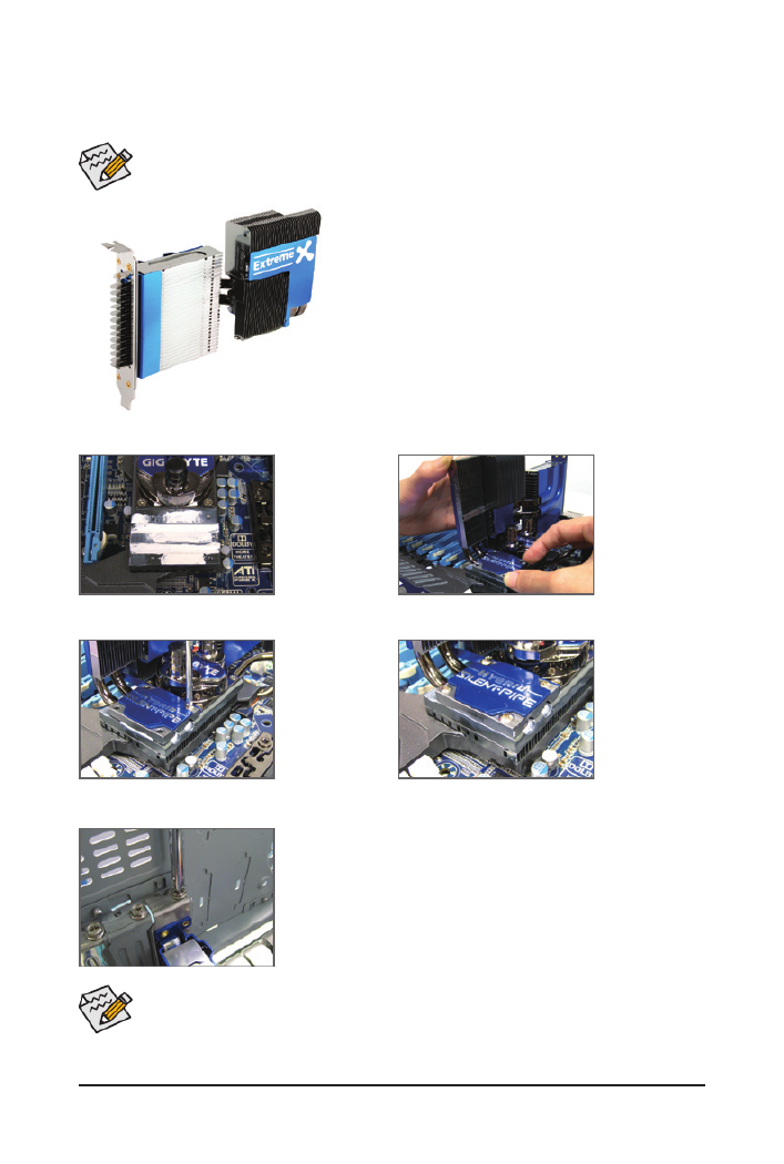
1-4 Installing the Hybrid Silent-Pipe Module
Read the following guideline before you begin to install the Hybrid Silent-Pipe module:
If you want to connect the front audio module from your chassis to the F_AUDIO connector on the moth-
erboard, be sure to connect it before installing the Hybrid Silent-Pipe module to avoid interference.
Hybrid Silent-Pipe
Tools needed:
1. A Philip's screwdriver
2. Thermal grease
3. Screws included with the motherboard
Follow the steps below to install the Hybrid Silent-Pipe module:
Step 1:
Apply an even thin
layer of thermal
g r e a s e o n th e
surface of the North
Bridge heatsink
base and it grooves.
Step 2:
Position the heat-
pipe underneath
the heatsink of the
Hybrid Silent-Pipe
module into the
tunnel of the North
Br idge h ea sin k
base.
Step 3:
Secure the Hybrid
Silent-Pipe heatsink
to the heatsink base
by the include d
screws.(Use one
hand to hold the top
of the fins to avoid
shaking.)
Step 4:
The picture on the
left shows that four
screws are fastened
to the heatsink and
heatsink base.
Step 5:
Secure the Hybrid Silent-Pipe bracket to the chassis back panel with a
screw to complete the installation.
For the waterblocks on the North Bridge heatsink, we recommend tubes with inner diameter of 7.5mm
and outer diameter of 10mm. After connecting the tubes, make sure that the tubes are attached to
the waterblocks securely and tightly and there is no leak.
(Note) The components received may vary in appearance from the products illustrated.

Hardware Installation - 18 -
1-5-2 Installing a Memory
Notch
DDR3 DIMM
ADDR3memorymodulehasanotch,soitcanonlytinonedirection.Followthestepsbelowtocorrectly
install your memory modules in the memory sockets.
Step 1:
Note the orientation of the memory module. Spread the retaining
clips at both ends of the memory socket. Place the memory module
onthesocket.Asindicatedinthepictureontheleft,placeyourn-
gers on the top edge of the memory, push down on the memory and
insert it vertically into the memory socket.
Step 2:
The clips at both ends of the socket will snap into place when the
memory module is securely inserted.
Before installing a memory module, make sure to turn off the computer and unplug the power
cord from the power outlet to prevent damage to the memory module.
DDR3 and DDR2 DIMMs are not compatible to each other or DDR DIMMs. Be sure to install
DDR3 DIMMs on this motherboard.

- 19 - Hardware Installation
1-6 Installing an Expansion Card
Follow the steps below to correctly install your expansion card in the expansion slot.
1. Locate an expansion slot that supports your card. Remove the metal slot cover from the chassis back panel.
2. Align the card with the slot, and press down on the card until it is fully seated in the slot.
3. Make sure the metal contacts on the card are completely inserted into the slot.
4. Secure the card’s metal bracket to the chassis back panel with a screw.
5. After installing all expansion cards, replace the chassis cover(s).
6. Turn on your computer. If necessary, go to BIOS Setup to make any required BIOS changes for your
expansion card(s).
7. Install the driver provided with the expansion card in your operating system.
Example: Installing and Removing a PCI Express Graphics Card:
• Installing a Graphics Card:
Gently push down on the top edge of the card until
it is fully inserted into the PCI Express slot. Make
sure the card is securely seated in the slot and
does not rock.
• Removing the Card:
Press the white latch at the end of the PCI Express slot to release the card and
then pull the card straight up from the slot.
Read the following guidelines before you begin to install an expansion card:
• Make sure the motherboard supports the expansion card. Carefully read the manual that came
with your expansion card.
• Always turn off the computer and unplug the power cord from the power outlet before installing
an expansion card to prevent hardware damage.
PCI Express x16 Slot

- 21 - Hardware Installation
C. Conguring the Graphics Card Driver
C-1. To Enable CrossFireX Function
C-2. To Enable SLI Function
For 2-Way CrossFireX:
After installing the
graphics card driver in
the operating system, go
to the Catalyst Control
Center. Browse t o the
CrossFireX menu and
select the Enable
CrossFireX™ check box.
Click to apply.OK
For 3-Way CrossFireX:
Browse to the CrossFireX
menu, select the Enable
CrossFireX™ check box,
and select the 3 GP Us
combination. Click to OK
apply.
Procedure and driver screen for enabling CrossFireX/SLI technology may differ by graphics cards.
Refer to the manual that came with your graphics cards for more information about enabling Cross-
FireX technology.
For 2-Way SLI:
After installing the graph-
ics c ar d d river in t he
op e ratin g s y s tem, go
to the NVIDIA Control
Panel. Browse to the
Set SLI and PhysX con-
figuration screen and
ensure andPhysX SLI
are enabled.
For 4-Way CrossFireX:
Browse to the CrossFireX
menu, select the Enable
CrossFireX™ check box,
and select the 4 GPUs
combination. Click to OK
apply.
For 3-Way SLI:
Browse to the Set SLI
and PhysX configura-
tion screen and ensure
PhysX 3-wa y and are
enabled.
For 4-Way SLI:
Browse to the Set SLI
and PhysX configura-
tion screen and ensure
PhysX Quad SLI and are
enabled.
Hardware Installation - 22 -
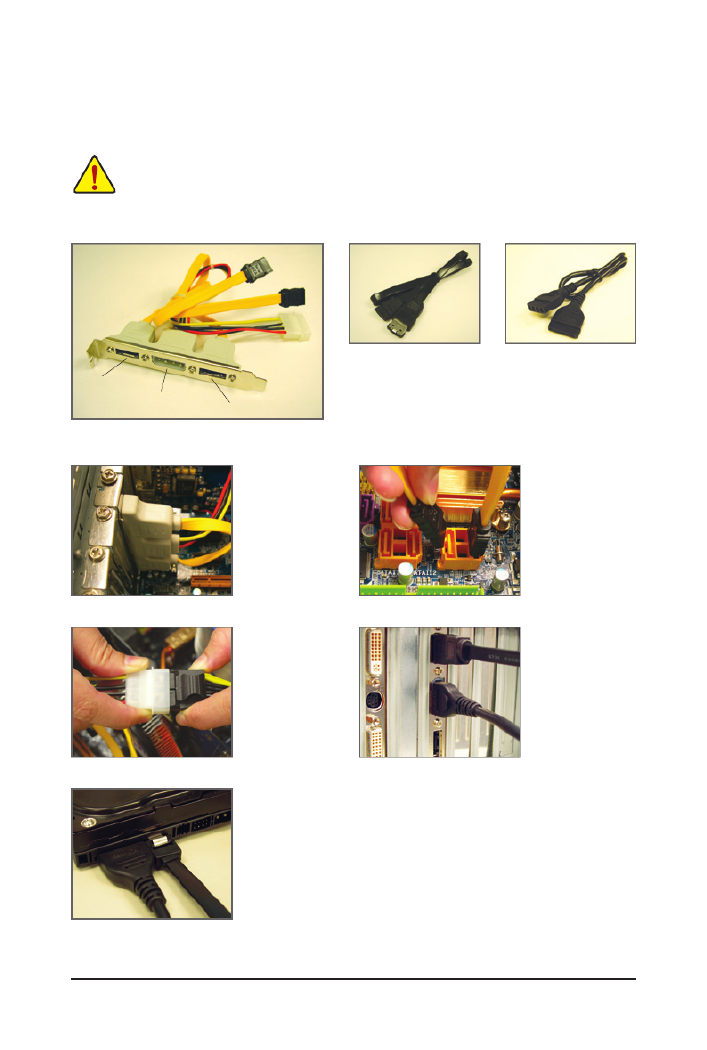
1-8 Installing the SATA Bracket
• Turn off your system and the power switch on the power supply before installing or removing the
SATA bracket and SATA power cable to prevent damage to hardware.
• Insert the SATA signal cable and SATA power cable securely into the corresponding connectors
when installing.
The SATA bracket allows you to connect external SATA device(s) to your system by expanding the internal
SATA port(s) to the chassis back panel.
Follow the steps below to install the SATA bracket:
The SATA bracket includes one SATA bracket, one
SATA signal cable, and one SATA power cable.
Step 1:
Locate one free PCI
slot and secure the
SATA bracket to the
chassis back panel
with a screw.
Step 2:
Connect the SATA ca-
ble from the bracket
to the SATA port on
your motherboard.
Step 3:
Connect the power
c a b l e f r o m t h e
bracket to the power
supply.
Step 4:
Plug one end of the
SATA signal cable
into the external SATA
c on n e c t or o n t h e
bracket. Then attach
the SATA power cable
to the power connec-
tor on the bracket.
Step 5:
Connect the other ends of the SATA signal cable and SATA power cable to
your SATA device. For SATA device in external enclosure, you only need to
connect the SATA signal cable. Before connecting the SATA signal cable,
make sure to turn off the power of the external enclosure.
External SATA Connector
Power Connector
External SATA
Connector
SATA Bracket SATA Signal Cable SATA Power Cable
- 23 - Hardware Installation
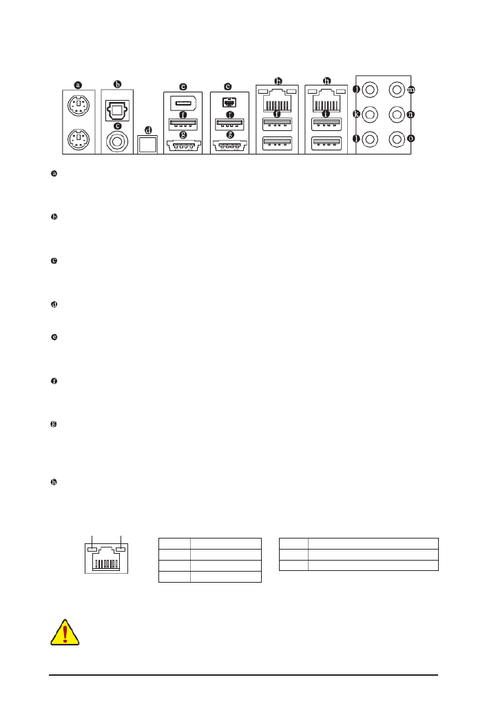
1-9 Back Panel Connectors
PS/2 Keyboard and PS/2 Mouse Port
Use the upper port (green) to connect a PS/2 mouse and the lower port (purple) to connect a PS/2 key-
board.
Optical S/PDIF Out Connector
This connector provides digital audio out to an external audio system that supports digital optical audio.
Before using this feature, ensure that your audio system provides an optical digital audio in connector.
Coaxial S/PDIF Out Connector
This connector provides digital audio out to an external audio system that supports digital coaxial audio.
Before using this feature, ensure that your audio system provides a coaxial digital audio in connector.
Clearing CMOS Button
Press the clearing CMOS switch to clear CMOS values.
IEEE 1394a Port
TheIEEE 1394port supportsthe IEEE1394a specication,featuringhighspeed,high bandwidthand
hotplug capabilities. Use this port for an IEEE 1394a device.
USB 2.0/1.1 Port
TheUSBportsupportstheUSB2.0/1.1specication.UsethisportforUSBdevicessuchasaUSBkey-
board/mouse,USBprinter,USBashdriveandetc.
eSATA/USB Combo Connector
ThisconnectorsupportsSATA3Gb/sandUSB2.0/1.1specication.Usetheporttoconnectanexternal
SATA device or a SATA port multiplier; or use this port for USB devices such as a USB keyboard/mouse,
USBprinter,USBashdriveandetc.
RJ-45 LAN Port
The Gigabit Ethernet LAN port provides Internet connection at up to 1 Gbps data rate. The following de-
scribes the states of the LAN port LEDs.
Activity LED:
State Description
Blinking Data transmission or receiving is occurring
Off No data transmission or receiving is occurring
Connection/Speed LED:
State Description
Orange 1 Gbps data rate
Green 100 Mbps data rate
Off 10 Mbps data rate
Activity LED
Connection/
Speed LED
LAN Port
• Whenremovingthecableconnectedtoabackpanelconnector,rstremovethecablefromyour
device and then remove it from the motherboard.
• When removing the cable, pull it straight out from the connector. Do not rock it side to side to
prevent an electrical short inside the cable connector.
clr
CMOS

Hardware Installation - 24 -
USB 3.0/2.0 Port
TheUSB3.0portsupportstheUSB3.0specicationandiscompatibletotheUSB2.0/1.1specication.
UsethisportforUSBdevicessuchasaUSBkeyboard/mouse,USBprinter,USBashdriveandetc.
Center/Subwoofer Speaker Out Jack (Orange)
Usethisaudiojacktoconnectcenter/subwooferspeakersina5.1/7.1-channelaudioconguration.
Rear Speaker Out Jack (Black)
Usethisaudiojacktoconnectrearspeakersina7.1-channelaudioconguration.
Side Speaker Out Jack (Gray)
Usethisaudiojacktoconnectsidespeakersina4/5.1/7.1-channelaudioconguration.
Line In Jack (Blue)
The default line in jack. Use this audio jack for line in devices such as an optical drive, walkman, etc.
Line Out Jack (Green)
The default line out jack. Use this audio jack for a headphone or 2-channel speaker. This jack can be
usedtoconnectfrontspeakersina4/5.1/7.1-channelaudioconguration.
Mic In Jack (Pink)
The default Mic in jack. Microphones must be connected to this jack.
In addition to the default speakers settings, the ~ audiojackscanbereconguredtoperform
different functions via the audio software. Only microphones still MUST be connected to the
default Mic in jack ( ). Refer to the instructions on setting up a 2/4/5.1/7.1-channel audio con-
gurationinChapter5,"Conguring2/4/5.1/7.1-ChannelAudio."
- 25 - Hardware Installation
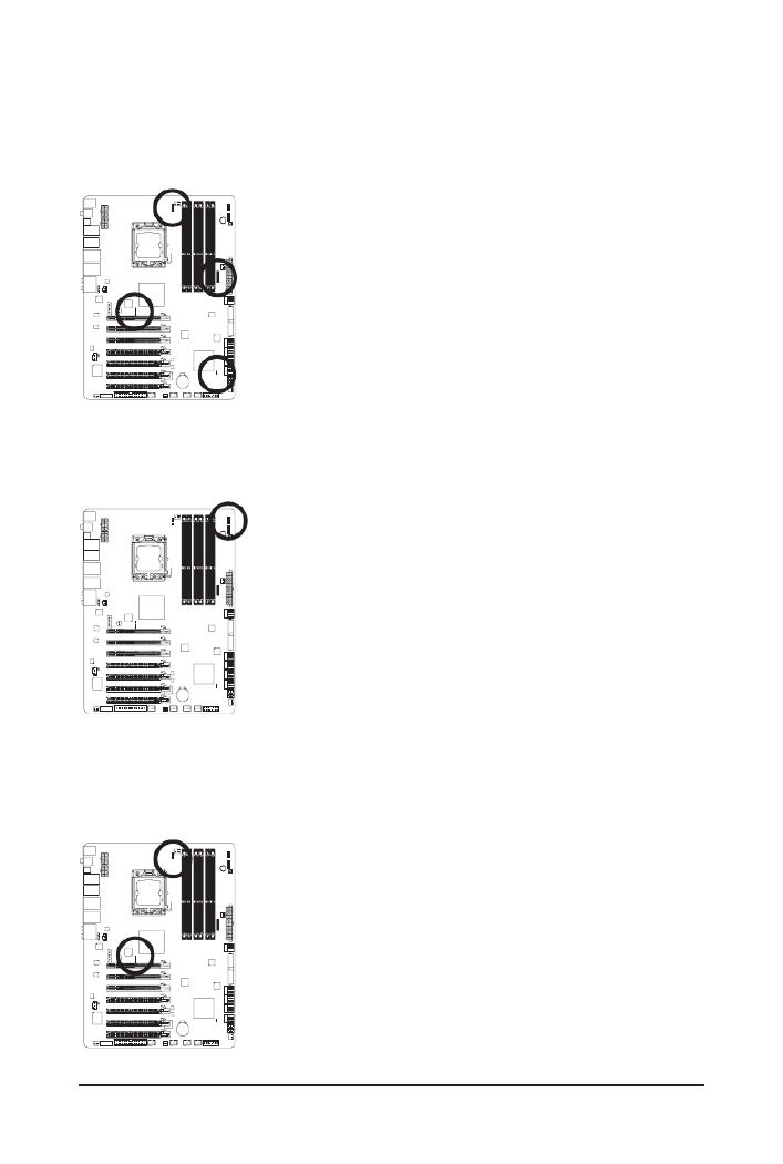
1-10 Onboard LEDs and Switches
Overvoltage LEDs
This motherboard contains 4 sets of overvoltage LEDs which indicate the overvoltage level of the CPU,
memory, North Bridge, and South Bridge.
CPU Voltage
Off: Normal condition
L1: Level 1 (Slight, green)
L2: Level 2 (Moderate, yellow)
L3: Level 3 (High, red)
NB Voltage
Off: Normal condition
L1: Level 1 (Slight, green)
L2: Level 2 (Moderate, yellow)
L3: Level 3 (High, red)
DDR Voltage
Off: Normal condition
L1: Level 1 (Slight, green)
L2: Level 2 (Moderate, yellow)
L3: Level 3 (High, red)
SB Voltage
Off: Normal condition
L1: Level 1 (Slight, green)
L2: Level 2 (Moderate, yellow)
L3: Level 3 (High, red)
Overclock LEDs
The onboard CPU overclock LEDs indicate on which level the CPU is overclocked. The higher the overclock
level, the more the number of lighted LEDs.
FREQ. LED
Off: Normal condition
F_LED1~F_LED5: Blue
Temperature Indicator LEDs
The two sets of temperature indicator LEDs indicate the temperature level of the CPU and North Bridge. The
LEDs are off when the temperature is below 60oC; the green LED lights up when the temperature is between
61~80oC; the red LED is illuminated when the temperature exceeds 80oC.
CPU TEMP
Off: Below 60oC
L1: 61~ 80oC (green)
L2: Over 80oC (red)
NB TEMP
Off: Below 60oC
L1: 61~ 80oC (green)
L2: Over 80oC (red)

Hardware Installation - 26 -
Quick Switches
This motherboard has 2 quick buttons: power button and reset button. The power button and reset button al-
low users to quickly turn on/off or reset the computer in an open-case environment when they want to change
hardware components or conduct hardware testing.
PW_SW: Power switch
RST_SW: Reset switch
PHASE LED
The number of lighted LEDs indicates the CPU loading. The higher the CPU loading, the more the number of
lightedLEDs.ToenablethePhaseLEDdisplayfunction,pleaserstenableDynamicEnergySaver2.Refer
to Chapter 4, "Dynamic Energy Saver 2," for more details.
NB PHASE LED
The number of lighted LEDs indicates the North Bridge loading. The higher the North Bridge loading, the
more the number of lighted LEDs.
Hardware Installation - 32 -
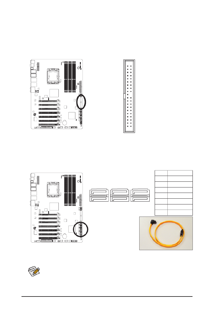
9) IDE (IDE Connector)
The IDE connector supports up to two IDE devices such as hard drives and optical drives. Before attach-
ing the IDE cable, locate the foolproof groove on the connector. If you wish to connect two IDE devices,
remember to set the jumpers and the cabling according to the role of the IDE devices (for example,
masterorslave).(Forinformationaboutconguringmaster/slavesettingsfortheIDEdevices,readthe
instructions from the device manufacturers.)
2
40
1
39
10) SATA2_0/1/2/3/4/5 (SATA 3Gb/s Connectors, Controlled by ICH10R)
The SATA connectors conform to SATA 3Gb/s standard and are compatible with SATA 1.5Gb/s stan-
dard. Each SATA connector supports a single SATA device. The ICH10R controller supports RAID 0,
RAID1,RAID5,andRAID10.RefertoChapter5,"ConguringSATAHardDrive(s),"forinstructionson
conguringaRAIDarray.
PinNo. Denition
1 GND
2 TXP
3 TXN
4 GND
5 RXN
6 RXP
7 GND
1
1
7
7
SATA2_0SATA2_2SATA2_4
SATA2_1SATA2_3SATA2_5
Please connect the L-shaped end of
the SATA 3Gb/s cable to your SATA
hard drive.
• ARAID 0 or RAID 1conguration requires at least two hard drives. If morethan two hard
drives are to be used, the total number of hard drives must be an even number.
• ARAID5congurationrequiresatleastthree harddrives.(Thetotalnumber ofhard drives
does not have to be an even number.)
• ARAID10congurationrequiresatleastfourharddrivesandthetotalnumberofharddrives
must be an even number.

- 33 - Hardware Installation
11) GSATA2_8/9 (SATA 3Gb/s Connectors, Controlled by GIGABYTE SATA2)
The SATA connectors conform to SATA 3Gb/s standard and are compatible with SATA 1.5Gb/s standard.
Each SATA connector supports a single SATA device. The GIGABYTE SATA2 controller supports RAID 0,
RAID1,andJBOD.RefertoChapter5,"ConguringSATAHardDrive(s),"forinstructionsonconguring
a RAID array.
PinNo. Denition
1 GND
2 TXP
3 TXN
4 GND
5 RXN
6 RXP
7 GND
7 1
7 1
GSATA2_8
GSATA2_9
ARAID0orRAID1congurationrequiresatleasttwoharddrives.Ifmorethantwoharddrives
are to be used, the total number of hard drives must be an even number.
12) GSATA3_6/7 (SATA 6Gb/s Connectors, Controlled by Marvell 9128)
The SATA connectors conform to SATA 6Gb/s standard and are compatible with SATA 3Gb/s and SATA
1.5Gb/s standards. Each SATA connector supports a single SATA device. The Marvell 9128 supports
RAID0andRAID1.RefertoChapter5,"ConguringSATAHardDrive(s),"forinstructionsoncongur-
ing a RAID array.
PinNo. Denition
1 GND
2 TXP
3 TXN
4 GND
5 RXN
6 RXP
7 GND
Please connect the L-shaped end of
the SATA 3Gb/s cable to your SATA
hard drive.
7 1
7 1
GSATA3_6
GSATA3_7
Termékspecifikációk
| Márka: | Gigabyte |
| Kategória: | alaplap |
| Modell: | GA-X58A-UD9 |
Szüksége van segítségre?
Ha segítségre van szüksége Gigabyte GA-X58A-UD9, tegyen fel kérdést alább, és más felhasználók válaszolnak Önnek
Útmutatók alaplap Gigabyte

14 Január 2025
13 Január 2025
12 Január 2025
12 Január 2025
12 Január 2025
9 Január 2025
9 Január 2025
9 Január 2025
9 Január 2025
9 Január 2025
Útmutatók alaplap
- alaplap Sharkoon
- alaplap Asus
- alaplap Supermicro
- alaplap Biostar
- alaplap Asrock
- alaplap MSI
- alaplap NZXT
- alaplap ECS
- alaplap Evga
- alaplap Intel
- alaplap Foxconn
- alaplap Advantech
- alaplap Elitegroup
- alaplap EPoX
Legújabb útmutatók alaplap

9 Április 2025
9 Április 2025
3 Április 2025
3 Április 2025
3 Április 2025
3 Április 2025
2 Április 2025
2 Április 2025

31 Március 2025
27 Március 2025