Használati útmutató Gigabyte GA-B85M-HD3 R4
Olvassa el alább 📖 a magyar nyelvű használati útmutatót Gigabyte GA-B85M-HD3 R4 (36 oldal) a alaplap kategóriában. Ezt az útmutatót 5 ember találta hasznosnak és 2 felhasználó értékelte átlagosan 4.5 csillagra
Oldal 1/36

GA-B85M-HD3 R4
User's Manual
Rev. 1001
12ME-85MHD3R-1001R

Motherboard
GA-B85M-HD3 R4
Feb. 17, 2015
Feb. 17, 2015
Motherboard
GA-B85M-HD3 R 4
Copyright
© 2015 GIGA-BYTE TECHNOLOGY CO., LTD. All rights reserved.
The trademarks mentioned in this manual are legally registered to their respective owners.
Disclaimer
Information in this manual is protected by copyright laws and is the property of GIGABYTE.
Changes to the specications and features in this manual may be made by GIGABYTE without prior notice.
No part of this manual may be reproduced, copied, translated, transmitted, or published in any form or by
any means without GIGABYTE's prior written permission.
In order to assist in the use of this product, carefully read the User's Manual.
For product-related information, check on our website at: http://www.gigabyte.com
Identifying Your Motherboard Revision
The revision number on your motherboard looks like this: "REV: X.X." For example, "REV: 1.0" means the
revision of the motherboard is 1.0. Check your motherboard revision before updating motherboard BIOS,
drivers, or when looking for technical information.
Example:

- 3 -
Table of Contents
GA-B85M-HD3 R4 Motherboard Layout 4 ..........................................................................
GA-B85M-HD3 R4 Motherboard Block Diagram 5 .............................................................
Chapter 1 Hardware Installation 6 .....................................................................................
1-1 Installation Precautions 6 ....................................................................................
1-2 Product Specications ...................................................................................... 7
1-3 Installing the CPU 9 ............................................................................................
1-4 Installing the Memory 10 .....................................................................................
1-5 Installing an Expansion Card 10 .........................................................................
1-6 Back Panel Connectors 10 ..................................................................................
1-7 Internal Connectors 12 ........................................................................................
Chapter 2 BIOS Setup 18 ..................................................................................................
2-1 Startup Screen 18 ...............................................................................................
2-2 M.I.T. .............................................................................................................. 19
2-3 System Information 24 ........................................................................................
2-4 BIOS Features 25 ...............................................................................................
2-5 Peripherals ..................................................................................................... 28
2-6 Power Management 30 .......................................................................................
2-7 Save & Exit 32 .....................................................................................................
Chapter 3 Appendix 33 ......................................................................................................
Drivers Installation 33 .....................................................................................................
Regulatory Statements 34 ..............................................................................................
Contact Us 36 ................................................................................................................
- 4 -
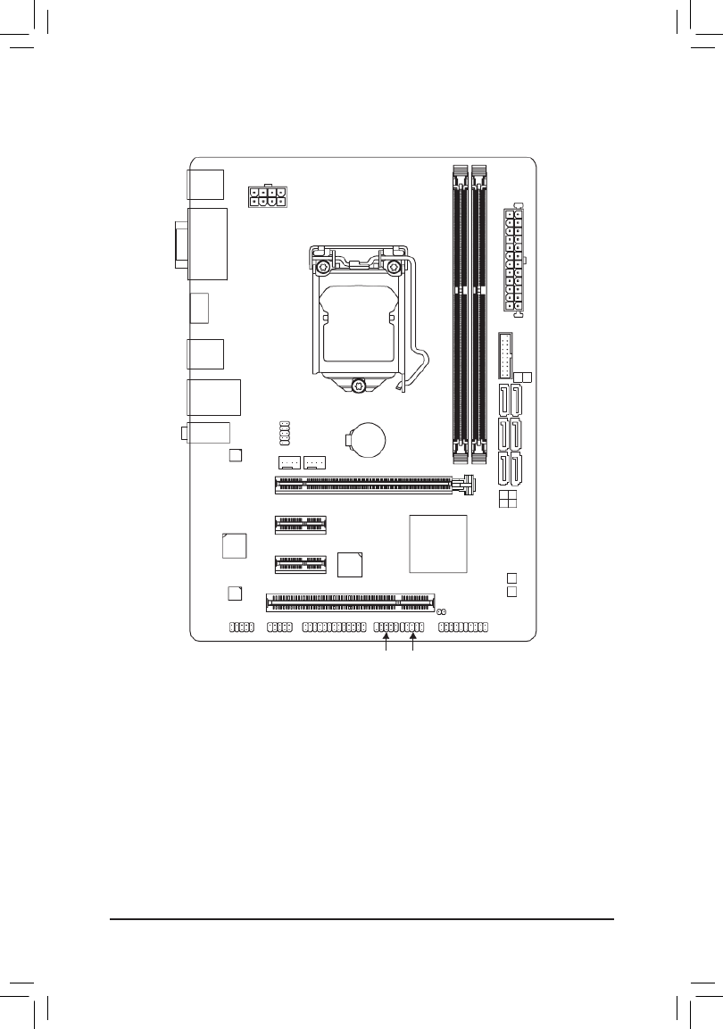
GA-B85M-HD3 R4 Motherboard Layout
The box contents above are for reference only and the actual items shall depend on the product package you obtain.
The box contents are subject to change without notice.
Box Contents
5GA-B85M-HD3 R4 motherboard
5Motherboard driver disk 5Two SATA cables
5User's Manual 5I/O Shield
KB_MS_USB
CPU_FAN SYS_FAN
LGA1150
ATX
GA-B85M-HD3 R4
F_AUDIO
AUDIO
M_BIOS
DDR3_1
DDR3_2
BAT
ATX_12V_2X4
Intel® B85
R_USB30
CODEC
CLR_CMOS
B_BIOS
VGA
DVI
LPT
USB_LAN
PCIEX16
PCIEX1_1
PCIEX1_2
PCI
iTE ®
Super I/O
Realtek
®
GbE LAN
F_USB2 F_USB1
F_USB30
COMB
HDMI
5
4
SATA3 SATA2
1 3
0 2
PCIe to PCI
Bridge
F_PANEL
COMA

- 5 -
GA-B85M-HD3 R4 Motherboard Block Diagram
For detailed product information/limitation(s), refer to "1-2 Product Specications."
iTE®
Super I/O
PS/2 KB/Mouse
LGA1150
CPU
Intel® B85
PCIe CLK
(100 MHz)
PCI Express Bus
CPU CLK+/- (100 MHz)
1 PCI Express x16
LPT
8 USB 2.0/1.1
4 USB 3.0/2.0
DDR3 1600/1333 MHz
PCI Express Bus
PCIe CLK
(100 MHz)
2 PCI Express x1
4 SATA 6Gb/s
D-Sub
DVI-D
2 SATA 3Gb/s
DMI 2.0
FDI
x16
Dual Channel Memory
x1 x1
x1
LAN
RJ45
Realtek®
GbE LAN
LPC
Bus
Line Out (Front Speaker Out)
MIC (Center/Subwoofer
Speaker Out)
Line In (Rear Speaker Out)
CODEC
HDMI
1 PCI
PCI Bus
PCI CLK
(33 MHz)
PCIe to PCI
Bridge
x1
Dual BIOS
COM

- 6 -
Chapter 1 Hardware Installation
1-1 Installation Precautions
The motherboard contains numerous delicate electronic circuits and components which can become
damaged as a result of electrostatic discharge (ESD). Prior to installation, carefully read the user's
manual and follow these procedures:
•Prior to installation, make sure the chassis is suitable for the motherboard.
•Prior to installation, do not remove or break motherboard S/N (Serial Number) sticker or
warranty sticker provided by your dealer. These stickers are required for warranty validation.
•Always remove the AC power by unplugging the power cord from the power outlet before
installing or removing the motherboard or other hardware components.
•When connecting hardware components to the internal connectors on the motherboard, make
sure they are connected tightly and securely.
•When handling the motherboard, avoid touching any metal leads or connectors.
•It is best to wear an electrostatic discharge (ESD) wrist strap when handling electronic
components such as a motherboard, CPU or memory. If you do not have an ESD wrist strap,
keep your hands dry and rst touch a metal object to eliminate static electricity.
•Prior to installing the motherboard, please have it on top of an antistatic pad or within an
electrostatic shielding container.
•Before unplugging the power supply cable from the motherboard, make sure the power supply
has been turned off.
•Before turning on the power, make sure the power supply voltage has been set according to
the local voltage standard.
•Before using the product, please verify that all cables and power connectors of your hardware
components are connected.
•To prevent damage to the motherboard, do not allow screws to come in contact with the
motherboard circuit or its components.
•Make sure there are no leftover screws or metal components placed on the motherboard or
within the computer casing.
•Do not place the computer system on an uneven surface.
•Do not place the computer system in a high-temperature environment.
•Turning on the computer power during the installation process can lead to damage to system
components as well as physical harm to the user.
•If you are uncertain about any installation steps or have a problem related to the use of the
product, please consult a certied computer technician.
- 7 -
1-2 ProductSpecications
CPU
Support for Intel® Core™ i7 processors/Intel® Core™ i5 processors/
Intel® Core™ i3 processors/Intel® Pentium® processors/
Intel® Celeron® processors in the LGA1150 package
(Go to GIGABYTE's website for the latest CPU support list.)
L3 cache varies with CPU
Chipset
Intel® B85 Express Chipset
Memory
2 x DDR3 DIMM sockets supporting up to 16 GB of system memory
* Due to a Windows 32-bit operating system limitation, when more than 4 GB of
physical memory is installed, the actual memory size displayed will be less than
the size of the physical memory installed.
Dual channel memory architecture
Support for DDR3 1600/1333 MHz memory modules
Support for non-ECC memory modules
Support for Extreme Memory Pro le (XMP) memory modules
(Go to GIGABYTE's website for the latest supported memory speeds and
memory modules.)
Onboard
Graphics
Integrated Graphics Processor- Intel® HD Graphics support:
- 1 x D-Sub port, supporting a maximum resolution of 1920x1200
- 1 x DVI-D port, supporting a maximum resolution of 1920x1200
* The DVI-D port does not support D-Sub connection by adapter.
- 1 x HDMI port, supporting a maximum resolution of 4096x2160
* Support for HDMI 1.4a version.
- Maximum shared memory of 1 GB
Audio
Realtek® ALC887 codec
High De nition Audio
2/4/5.1/7.1-channel
* To con gure 7.1-channel audio, you have to use an HD front panel audio module
and enable the multi-channel audio feature through the audio driver.
LAN
Realtek® GbE LAN chip (10/100/1000 Mbit)
Expansion Slots 1 x PCI Express p7-x16 slot, running at x16
(The PCI Express p7-x16 slot conforms to PCI Express 3.0 standard.)
2 x PCI Express p7-x1 slots
(The PCI Express p7-x1 slots conform to PCI Express 2.0 standard.)
1 x PCI slot
Storage Interface
Chipset:
- 4 x SATA 6Gb/s connectors (SATA3 0/1/2/3)
- 2 x SATA 3Gb/s connectors (SATA2 4/5)
USB
Chipset:
- 4 x USB 3.0/2.0 ports (2 ports on the back panel, 2 ports available through
the internal USB header)
- 8 x USB 2.0/1.1 ports (4 ports on the back panel, 4 ports available through
the internal USB headers)
Internal
Connectors
1 x 24-pin ATX main power connector
1 x 8-pin ATX 12V power connector
4 x SATA 6Gb/s connectors

- 8 -
Internal
Connectors
2 x SATA 3Gb/s connectors
1 x CPU fan header
1 x system fan header
1 x front panel header
1 x front panel audio header
1 x USB 3.0/2.0 header
2 x USB 2.0/1.1 headers
2 x serial port headers
1 x parallel port header
1 x Clear CMOS jumper
Back Panel
Connectors
1 x PS/2 keyboard/mouse port
1 x D-Sub port
1 x DVI-D port
1 x HDMI port
2 x USB 3.0/2.0 ports
4 x USB 2.0/1.1 ports
1 x RJ-45 port
3 x audio jacks (Line In, Line Out, Microphone)
I/O Controller
iTE® I/O Controller Chip
Hardware
Monitor
System voltage detection
CPU/System temperature detection
CPU/System fan speed detection
CPU/System overheating warning
CPU/System fan fail warning
CPU/System fan speed control
* Whether the fan speed control function is supported will depend on the cooler you
install.
BIOS
2 x 32 Mbit ash
Use of licensed AMI UEFI BIOS
Support for DualBIOS™
PnP 1.0a, DMI 2.7, WfM 2.0, SM BIOS 2.7, ACPI 5.0
Unique Features
Support for Q-Flash
Support for Xpress Install
Support for APP Center
* Available applications in APP Center may differ by motherboard model. Supported
functions of each application may also differ depending on motherboard
speci cations.
- @BIOS
- EasyTune
- EZ Setup
- USB Blocker
- Smart TimeLock
- Smart Recovery 2
- Fast Boot
Support for ON/OFF Charge
- 9 -
Bundled
Software
Norton® Internet Security (OEM version)
Intel® Rapid Start Technology
Intel® Smart Connect Technology
Operating
System
Support for Windows 8.1/8/7
Form Factor
Micro ATX Form Factor; 24.4cm x 17.4cm
* GIGABYTE reserves the right to make any changes to the product speci cations and product-related information without
prior notice.
* Please visit the Support & Downloads\Utility page on GIGABYTE's website to check the supported operating system(s)
for the software listed in the "Unique Features" and "Bundled Software" columns.
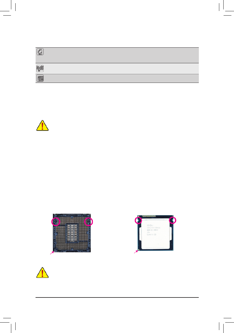
1-3 Installing the CPU
Read the following guidelines before you begin to install the CPU:
•Make sure that the motherboard supports the CPU.
(Go to GIGABYTE's website for the latest CPU support list.)
•Always turn off the computer and unplug the power cord from the power outlet before installing the
CPU to prevent hardware damage.
•Locate the pin one of the CPU. The CPU cannot be inserted if oriented incorrectly. (Or you may
locate the notches on both sides of the CPU and alignment keys on the CPU socket.)
•Apply an even and thin layer of thermal grease on the surface of the CPU.
•Do not turn on the computer if the CPU cooler is not installed, otherwise overheating and damage
of the CPU may occur.
•Set the CPU host frequency in accordance with the CPU specications. It is not recommended
that the system bus frequency be set beyond hardware specications since it does not meet the
standard requirements for the peripherals. If you wish to set the frequency beyond the standard
specications, please do so according to your hardware specications including the CPU, graphics
card, memory, hard drive, etc.
Installing the CPU
Locate the alignment keys on the motherboard CPU socket and the notches on the CPU.
A li gn men t
Key
Alignment
Key
LGA1150 CPU Socket
Pin One Corner of the CPU Socket
NotchNotch
LGA1150 CPU
Triangle Pin One Marking on the CPU
Do not remove the CPU socket cover before inserting the CPU. It may pop off from the load plate
automatically during the process of re-engaging the lever after you insert the CPU.

- 10 -
DualChannelMemoryConguration
This motherboard provides two DDR3 memory sockets and supports Dual Channel Technology. After the memory
is installed, the BIOS will automatically detect the specications and capacity of the memory. Enabling Dual
Channel memory mode will double the original memory bandwidth.
The two DDR3 memory sockets are divided into two channels and each channel has one memory socket as
following:
Channel A: DDR3_1
Channel B: DDR3_2
Due to CPU limitations, read the following guidelines before installing the memory in Dual Channel mode.
1. Dual Channel mode cannot be enabled if only one DDR3 memory module is installed.
2. When enabling Dual Channel mode with two memory modules, it is recommended that memory of
the same capacity, brand, speed, and chips be used for optimum performance.
1-5 Installing an Expansion Card
Read the following guidelines before you begin to install an expansion card:
•Make sure the motherboard supports the expansion card. Carefully read the manual that came
with your expansion card.
•Always turn off the computer and unplug the power cord from the power outlet before installing an
expansion card to prevent hardware damage.
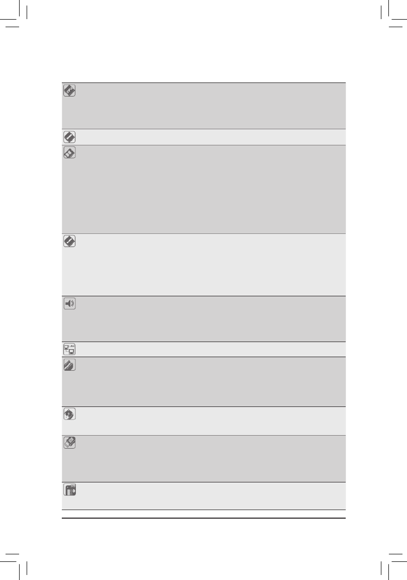
1-6 Back Panel Connectors
USB 2.0/1.1 Port
The USB port supports the USB 2.0/1.1 specication. Use this port for USB devices such as a USB
keyboard/mouse, USB printer, USB ash drive and etc.
PS/2 Keyboard/Mouse Port
Use this port to connect a PS/2 mouse or keyboard.
D-Sub Port
The D-Sub port supports a 15-pin D-Sub connector and supports a maximum resolution of 1920x1200
(the actual resolutions supported depend on the monitor being used). Connect a monitor that supports
D-Sub connection to this port.
1-4 Installing the Memory
Read the following guidelines before you begin to install the memory:
•Make sure that the motherboard supports the memory. It is recommended that memory of the
same capacity, brand, speed, and chips be used.
(Go to GIGABYTE's website for the latest supported memory speeds and memory modules.)
•Always turn off the computer and unplug the power cord from the power outlet before installing the
memory to prevent hardware damage.
•Memory modules have a foolproof design. A memory module can be installed in only one direction.
If you are unable to insert the memory, switch the direction.

- 11 -
DVI-D Port (Note)
The DVI-D port conforms to the DVI-D specication and supports a maximum resolution of 1920x1200
(the actual resolutions supported depend on the monitor being used). Connect a monitor that supports
DVI-D connection to this port.
HDMI Port
The HDMI port is HDCP compliant and supports Dolby True HD and DTS HD
Master Audio formats. It also supports up to 192KHz/24bit 8-channel LPCM audio
output. You can use this port to connect your HDMI-supported monitor. The maximum supported resolution
is 4096x2160, but the actual resolutions supported are dependent on the monitor being used.
•When removing the cable connected to a back panel connector, rst remove the cable from your
device and then remove it from the motherboard.
•When removing the cable, pull it straight out from the connector. Do not rock it side to side to prevent
an electrical short inside the cable connector.
To congure 7.1-channel audio, you have to use an HD front panel audio module and enable the
multi-channel audio feature through the audio driver.
Line In Jack (Blue)
The line in jack. Use this audio jack for line in devices such as an optical drive, walkman, etc.
Line Out Jack (Green)
The line out jack. Use this audio jack for a headphone or 2-channel speaker. This jack can be used to
connect front speakers in a 4/5.1/7.1-channel audio conguration.
Mic In Jack (Pink)
The Mic in jack. Microphones must be connected to this jack.
Activity LED
Connection/
Speed LED
LAN Port
Connection/Speed LED:
State Description
Orange 1 Gbps data rate
Green 100 Mbps data rate
Off 10 Mbps data rate
Activity LED:
State Description
Blinking Data transmission or receiving is occurring
Off No data transmission or receiving is occurring
(Note) The DVI-D port does not support D-Sub connection by adapter.
TripleDisplayCongurationsfortheOnboardGraphics:
Triple-display congurations are supported after you install motherboard drivers in OS. Only dual-display
congurations are supported during the BIOS Setup or POST process.
USB 3.0/2.0 Port
The USB 3.0 port supports the USB 3.0 specication and is compatible to the USB 2.0/1.1 specication.
Use this port for USB devices such as a USB keyboard/mouse, USB printer, USB ash drive and etc.
RJ-45 LAN Port
The Gigabit Ethernet LAN port provides Internet connection at up to 1 Gbps data rate. The following
describes the states of the LAN port LEDs.
After installing the HDMI device, make sure to set the default sound playback device to HDMI.

- 12 -
1-7 Internal Connectors
Read the following guidelines before connecting external devices:
•First make sure your devices are compliant with the connectors you wish to connect.
•Before installing the devices, be sure to turn off the devices and your computer. Unplug the power
cord from the power outlet to prevent damage to the devices.
•After installing the device and before turning on the computer, make sure the device cable has
been securely attached to the connector on the motherboard.
1
9
8
2
1) ATX_12V_2X4
2) ATX
3) CPU_FAN
4) SYS_FAN
5) SATA3 0/1/2/3
6) SATA2 4/5
7) F_AUDIO
8) F_PANEL
9) F_USB30
10) F_USB1/F_USB2
11) COMA/COMB
12) LPT
13) CLR_CMOS
14) BAT
5
12117
14 6
10
4
3
13
11

- 13 -
1/2) ATX_12V_2X4/ATX (2x4 12V Power Connector and 2x12 Main Power Connector)
With the use of the power connector, the power supply can supply enough stable power to all the components
on the motherboard. Before connecting the power connector, rst make sure the power supply is turned
off and all devices are properly installed. The power connector possesses a foolproof design. Connect the
power supply cable to the power connector in the correct orientation.
The 12V power connector mainly supplies power to the CPU. If the 12V power connector is not connected,
the computer will not start.
3/4) CPU_FAN/SYS_FAN (Fan Headers)
All fan headers on this motherboard are 4-pin. Most fan headers possess a foolproof insertion design.
When connecting a fan cable, be sure to connect it in the correct orientation (the black connector wire is
the ground wire). The speed control function requires the use of a fan with fan speed control design. For
optimum heat dissipation, it is recommended that a system fan be installed inside the chassis.
To meet expansion requirements, it is recommended that a power supply that can withstand high power consumption
be used (500W or greater). If a power supply is used that does not provide the required power, the result can
lead to an unstable or unbootable system.
ATX_12V_2X4:
Pin No. Pin No.Denition Denition
1 5 +12V (Only for 2x4-pin 12V)GND (Only for 2x4-pin 12V)
2 6 +12V (Only for 2x4-pin 12V)GND (Only for 2x4-pin 12V)
3 GND 7 +12V
4 GND 8 +12V
131
2412
ATX
ATX:
Pin No. Pin No.Denition Denition
1 3.3V 13 3.3V
2 3.3V 14 -12V
3 GND 15 GND
4 +5V 16 PS_ON (soft On/Off)
5 GND 17 GND
6 +5V 18 GND
7 GND 19 GND
8 Power Good 20 -5V
9 5VSB (stand by +5V) 21 +5V
10 +12V 22 +5V
11 +12V (Only for 2x12-pin
ATX)
23 +5V (Only for 2x12-pin ATX)
12 3.3V (Only for 2x12-pin
ATX)
24 GND (Only for 2x12-pin ATX)
CPU_FAN:
Pin No. Denition
1 GND
2 +12V
3 Sense
4 Speed Control
•Be sure to connect fan cables to the fan headers to prevent your CPU and system from overheating. Overheating
may result in damage to the CPU or the system may hang.
•These fan headers are not conguration jumper blocks. Do not place a jumper cap on the headers.
ATX_12V_2X4
5 8
1 4
CPU_FAN/SYS_FAN
1
SYS_FAN:
Pin No. Denition
1 GND
2 +12V /Speed Control
3 Sense
4 VCC

- 14 -
5) SATA3 0/1/2/3 (SATA 6Gb/s Connectors)
The SATA connectors conform to SATA 6Gb/s standard and are compatible with SATA 3Gb/s and SATA
1.5Gb/s standard. Each SATA connector supports a single SATA device.
Pin No. Denition
1 GND
2 TXP
3 TXN
4 GND
5 RXN
6 RXP
7 GND
SATA3
3 2
1 0
77
11
6) SATA2 4/5 (SATA 3Gb/s Connectors)
The SATA connectors conform to SATA 3Gb/s standard and are compatible with SATA 1.5Gb/s standard.
Each SATA connector supports a single SATA device.
Pin No. Denition
1 GND
2 TXP
3 TXN
4 GND
5 RXN
6 RXP
7 GND
SATA2
7
7
11
5 4
7) F_AUDIO (Front Panel Audio Header)
The front panel audio header supports Intel High Denition audio (HD) and AC'97 audio. You may connect
your chassis front panel audio module to this header. Make sure the wire assignments of the module
connector match the pin assignments of the motherboard header. Incorrect connection between the module
connector and the motherboard header will make the device unable to work or even damage it.
For HD Front Panel Audio: For AC'97 Front Panel Audio:
Pin No. Denition
1 MIC2_L
2 GND
3 MIC2_R
4 -ACZ_DET
5 LINE2_R
6 Sense
7 FAUDIO_JD
8 No Pin
9 LINE2_L
10 Sense
Pin No. Denition
1 MIC
2 GND
3 MIC Power
4 NC
5 Line Out (R)
6 NC
7 NC
8 No Pin
9 Line Out (L)
10 NC
•The front panel audio header supports HD audio by default.
•Audio signals will be present on both of the front and back panel audio connections simultaneously.
•Some chassis provide a front panel audio module that has separated connectors on each wire instead of a
single plug. For information about connecting the front panel audio module that has different wire assignments,
please contact the chassis manufacturer.
1
2
9
10
To enable hot-plugging for the SATA ports, refer to Chapter 2, "BIOS Setup," "Peripherals\SATA
Conguration," for more information.
- 15 -
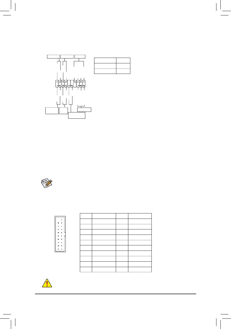
8) F_PANEL (Front Panel Header)
Connect the power switch, reset switch, speaker, and system status indicator on the chassis to this header
according to the pin assignments below. Note the positive and negative pins before connecting the cables.
•PW (Power Switch):
Connects to the power switch on the chassis front panel. You may
congure the way to turn off your system using the power switch
(refer to Chapter 2, "BIOS Setup," "Power Management," for more
information).
•SPEAK (Speaker):
Connects to the speaker on the chassis front panel. The system
reports system startup status by issuing a beep code. One single
short beep will be heard if no problem is detected at system startup.
•PLED/PWR_LED (Power LED):
System Status LED
S0 On
S3/S4/S5 Off
Connects to the power status indicator
on the chassis front panel. The LED is on
when the system is operating. The LED is
off when the system is in S3/S4 sleep state
or powered off (S5).
The front panel design may differ by chassis. A front panel module mainly consists of power switch, reset switch,
power LED, hard drive activity LED, speaker and etc. When connecting your chassis front panel module to this
header, make sure the wire assignments and the pin assignments are matched correctly.
•HD (Hard Drive Activity LED):
Connects to the hard drive activity LED on the chassis front panel. The LED is on when the hard drive is
reading or writing data.
•RES (Reset Switch):
Connects to the reset switch on the chassis front panel. Press the reset switch to restart the computer if the
computer freezes and fails to perform a normal restart.
•CI (Chassis Intrusion Header):
Connects to the chassis intrusion switch/sensor on the chassis that can detect if the chassis cover has been
removed. This function requires a chassis with a chassis intrusion switch/sensor.
•NC:
No Connection.
Power LED
1
2
19
20
CI-
CI+
PWR_LED+
PLED-
PW-
SPEAK+
SPEAK-
PLED+
PW+
Power LED
HD-
RES+
HD+
RES-
Hard Drive
Activity LED
Reset
Switch Chassis Intrusion
Header
Power Switch Speaker
PWR_LED-
PWR_LED-
9) F_USB30 (USB 3.0/2.0 Header)
The header conforms to USB 3.0/2.0 specication and can provide two USB ports. For purchasing the
optional 3.5" front panel that provides two USB 3.0/2.0 ports, please contact the local dealer.
Pin No. Pin No.Denition Denition
1 VBUS D2+11
2 SSRX1- 12 D2-
3 SSRX1+ 13 GND
4 GND 14 SSTX2+
5 SSTX1- 15 SSTX2-
6 SSTX1+ 16 GND
7 GND 17 SSRX2+
8 D1- 18 SSRX2-
9 D1+ 19 VBUS
10 NC 20 No Pin
10
11
20 1
Prior to installing the USB front panel, be sure to turn off your computer and unplug the power cord from the power
outlet to prevent damage to the USB front panel.
NC
NC

- 16 -
10) F_USB1/2 (USB 2.0/1.1 Headers)
The headers conform to USB 2.0/1.1 specication. Each USB header can provide two USB ports via an
optional USB bracket. For purchasing the optional USB bracket, please contact the local dealer.
Pin No. Pin No.Denition Denition
1 Power (5V) 6 USB DY+
2 Power (5V) 7 GND
3 USB DX- 8 GND
4 USB DY- 9 No Pin
5 USB DX+ 10 NC
•Do not plug the IEEE 1394 bracket (2x5-pin) cable into the USB header.
•Prior to installing the USB bracket, be sure to turn off your computer and unplug the power cord from the power
outlet to prevent damage to the USB bracket.
10
9
2
1
11) COMA/COMB (Serial Port Headers)
The COM header can provide one serial port via an optional COM port cable. For purchasing the optional
COM port cable, please contact the local dealer.
Pin No. Pin No.Denition Denition
1 NDCD- 6 NDSR-
2 NSIN 7 NRTS-
3 NSOUT 8 NCTS-
4 NDTR- 9 NRI-
5 GND 10 No Pin
12) LPT (Parallel Port Header)
The LPT header can provide one parallel port via an optional LPT port cable. For purchasing the optional
LPT port cable, please contact the local dealer.
Pin No. Pin No.Denition Denition
1 STB- 14 GND
2 AFD- 15 PD6
3 PD0 16 GND
4 ERR- 17 PD7
5 PD1 18 GND
6 INIT- 19 ACK-
7 PD2 20 GND
8 SLIN- 21 BUSY
9 PD3 22 GND
10 GND 23 PE
11 PD4 24 No Pin
12 GND 25 SLCT
13 PD5 26 GND
26
25
2
1
10
9
2
1
9
1
10
2
Termékspecifikációk
| Márka: | Gigabyte |
| Kategória: | alaplap |
| Modell: | GA-B85M-HD3 R4 |
Szüksége van segítségre?
Ha segítségre van szüksége Gigabyte GA-B85M-HD3 R4, tegyen fel kérdést alább, és más felhasználók válaszolnak Önnek
Útmutatók alaplap Gigabyte

14 Január 2025
13 Január 2025
12 Január 2025
12 Január 2025
12 Január 2025
9 Január 2025
9 Január 2025
9 Január 2025
9 Január 2025
9 Január 2025
Útmutatók alaplap
- alaplap Sharkoon
- alaplap Asus
- alaplap Supermicro
- alaplap Biostar
- alaplap Asrock
- alaplap MSI
- alaplap NZXT
- alaplap ECS
- alaplap Evga
- alaplap Intel
- alaplap Foxconn
- alaplap Advantech
- alaplap Elitegroup
- alaplap EPoX
Legújabb útmutatók alaplap

9 Április 2025
9 Április 2025
3 Április 2025
3 Április 2025
3 Április 2025
3 Április 2025
2 Április 2025
2 Április 2025

31 Március 2025
27 Március 2025