Használati útmutató Flir SyncroIP DNB14UX2
Flir
Térfigyelő kamera
SyncroIP DNB14UX2
Olvassa el alább 📖 a magyar nyelvű használati útmutatót Flir SyncroIP DNB14UX2 (76 oldal) a Térfigyelő kamera kategóriában. Ezt az útmutatót 2 ember találta hasznosnak és 2 felhasználó értékelte átlagosan 4.5 csillagra
Oldal 1/76

www. m/proflirsecurity.co
Copyright © 2014 FLIR Systems, Inc.
Instruction Manual
English Version 2.0
DNB14UX2
IR Bullet IP Camera
Thank you for purchasing this product. FLIR is committed to providing our
customers with a high quality, reliable security solution.
This manual refers to the following models:
• DNB14UX2
For more information on this product, firmware updates, and accessory products,
please visit us at:
www.flirsecurity.com/pro
CAUTION
RISK OF ELECTRIC SHOCK
DO NOT OPEN
CAUTION: TO REDUCE THE RISK OF ELECTRIC SHOCK DO NOT
REMOVE COVER. NO USER SERVICABLE PARTS INSIDE.
REFER SERVICING TO QUALIFIED SERVICE PERSONNEL.
The lightning flash with arrowhead symbol, within an
equilateral triangle, is intended to alert the user to the
presence of uninsulated "dangerous voltage" within the
product's enclosure that may be of sufficient magnitude to
constitute a risk of electric shock.
The exclamation point within an equilateral triangle is
intended to alert the user to the presence of important
operating and maintenance (servicing) instructions in the
literature accompanying the appliance.
WARNING: TO PREVENT FIRE OR SHOCK HAZARD, DO NOT
EXPOSE THIS UNIT TO RAIN OR MOISTURE.
CAUTION: TO PREVENT ELECTRIC SHOCK, MATCH WIDE BLADE
OF THE PLUG TO THE WIDE SLOT AND FULLY INSERT.

i
Important Safeguards
In addition to the careful attention devoted to quality standards in the manufacturing process of
your video product, safety is a major factor in the design of every instrument. However, safety is
your responsibility too. This sheet lists important information that will help to assure your
enjoyment and proper use of the video product and accessory equipment. Please read them
carefully before operating and using your video product.
Installation
1. Read and Follow Instructions - All the safety and
operating instructions should be read before the
video product is operated. Follow all operating
instructions.
2. - The safety and operating Retain Instructions
instructions should be retained for future reference.
3. Heed Warnings - Comply with all warnings on the
video product and in the operating instructions.
4. - Do not defeat the Polarization
safety purpose of the polarized or
grounding-type plug.
A polarized plug has two blades
with one wider than the other.
A grounding type plug has two
blades and a third grounding prong.
The wide blade or the third prong
are provided for your safety.
If the provided plug does not fit into your outlet,
consult an electrician for replacement of the
obsolete outlet.
5. Power Sources - This video product should be
operated only from the type of power source
indicated on the marking label. If you are not sure of
the type of power supply to your location, consult
your video dealer or local power company. For video
products intended to operate from battery power, or
other sources, refer to the operating instructions.
6. Overloading - Do not overload wall outlets of
extension cords as this can result in the risk of fire
or electric shock. Overloaded AC outlets, extension
cords, frayed power cords, damaged or cracked wire
insulation, and broken plugs are dangerous. They
may result in a shock or fire hazard. Periodically
examine the cord, and if its appearance indicates
damage or deteriorated insulation, have it replaced
by your service technician.
7. Power Cord Protection - Power supply cords should
be routed so that they are not likely to be walked on
or pinched by items placed upon or against them,
paying particular attention to cords at plugs,
convenience receptacles, and the point where they
exit from the video product.
8. Ventilation - Slots and openings in the case are
provided for ventilation to ensure reliable operation
of the video product and to protect it from
overheating. These openings must not be blocked or
covered. The openings should never be blocked by
placing the video equipment on a bed, sofa, rug, or
other similar surface. This video product should
never be placed near or over a radiator or heat
register. This video product should not be placed in a
built-in installation such as a bookcase or rack
unless proper ventilation is provided or the video
product manufacturer’s instructions have been
followed.
9. - Do not use attachments unless Attachments
recommended by the video product manufacturer as
they may cause a hazard.
10. Camera Extension Cables – Check the rating of
your extension cable(s) to verify compliance with
your local authority regulations prior to installation.
11. Water and Moisture - Do not use this video product
near water. For example, near a bath tub, wash
bowl, kitchen sink or laundry tub, in a wet
basement, near a swimming pool and the like.
Caution: Maintain electrical safety. Powerline
operated equipment or accessories connected to
this unit should bear the UL listing mark of CSA
certification mark on the accessory itself and should
not be modified so as to defeat the safety features.
This will help avoid any potential hazard from
electrical shock or fire. If in doubt, contact qualified
service personnel.
12. Accessories - Do not place this
video equipment on an unstable
cart, stand, tripod, or table. The
video equipment may fall, causing
serious damage to the video
product. Use this video product
only with a cart, stand, tripod,
bracket, or table recommended by the
manufacturer or sold with the video product. Any
mounting of the product should follow the
manufacturer’s instructions and use a mounting
accessory recommended by the manufacturer.

ii
G
Service
13. - Do not attempt to service this video Servicing
equipment yourself as opening or removing covers
may expose you to dangerous voltage or other
hazards. Refer all servicing to qualified service
personnel.
14. - Unplug this video Conditions Requiring Service
product from the wall outlet and refer servicing to
qualified service personnel under the following
conditions:
• When the power supply cord or plug is damaged.
• If liquid has been spilled or objects have fallen into
the video product.
• If the video product has been exposed to rain or
water.
• If the video product does not operate normally by
following the operating instructions. Adjust only
those controls that are covered by the operating
instructions. Improper adjustment of other controls
may result in damage and will often require
extensive work by a qualified technician to restore
the video product to its normal operation.
• If the video product has been dropped or the cabinet
has been damaged.
• When the video product exhibits a distinct change
in performance. This indicates a need for service.
15. Replacement Parts - When replacement parts are
required, have the service technician verify that the
replacements used have the same safety
characteristics as the original parts. Use of
replacements specified by the video product
manufacturer can prevent fire, electric shock or
other hazards.
16. - Upon completion of any service or Safety Check
repairs to this video product, ask the service
technician to perform safety checks recommended
by the manufacturer to determine that the video
product is in safe operating condition.
17. Wall or Ceiling Mounting - The cameras provided
should be mounted to a wall or ceiling only as
instructed in this guide, using the provided
mounting brackets.
18. - The product should be situated away from Heat
heat sources such as radiators, heat registers,
stoves, or other products (including amplifiers) that
produce heat.
Use
19. - Unplug the video product from the wall Cleaning
outlet before cleaning. Do not use liquid cleaners or
aerosol cleaners. Use a damp cloth for cleaning.
20. Product and Cart Combination - Video and cart
combination should be moved with care. Quick
stops, excessive force, and uneven surfaces may
cause the video product and cart combination to
overturn.
21. Object and Liquid Entry - Never push objects of any
kind into this video product through openings as
they may touch dangerous voltage points or
“short-out” parts that could result in a fire or
electric shock. Never spill liquid of any kind on the
video product.
22. - For added protection for this video Lightning
product during a lightning storm, or when it is left
unattended and unused for long periods of time,
unplug it from the wall outlet and disconnect the
antenna or cable system. This will prevent damage
to the video product due to lightning and power line
surges.

iii
General Precautions
1. All warnings and instructions in this manual should be followed.
2. Remove the plug from the outlet before cleaning. Do not use liquid aerosol detergents. Use a
water dampened cloth for cleaning.
3. Keep enough space around the unit for ventilation. Slots and openings in the storage cabinet
should not be blocked.
4. During lightning storms, or when the unit is not used for a long time, disconnect the power
supply, antenna, and cables to protect the unit from electrical surge.
FCC CLASS A NOTICE
NOTE
This equipment has been tested and found to comply with the limits for a Class A digital device
pursuant to Part 15 of the FCC Rules. These limits are designed to provide reasonable protection
against harmful interference when the equipment is operated in a commercial environment. This
equipment generates, uses, and can radiate radio frequency energy and, if not installed and used
in accordance with the manufacturer’s instruction manual, may cause harmful interference with
radio communications. Operation of this equipment in a residential area is likely to cause harmful
interference, in which case you will be required to correct the interference at your own expense.
This equipment has been certified and found to comply with the limits regulated by FCC, EMC, and
LVD. Therefore, it is designated to provide reasonable protection against interference and will not
cause interference with other appliance usage.
However, it is imperative that the user follows the guidelines in this manual to avoid improper
usage which may result in damage to the unit, electrical shock and fire hazard injury.
In order to improve the feature functions and quality of this product, the specifications are subject
to change without notice from time to time.
www.irsecurity.com/pro

iv
Features
• 2.1 MP HD, 1/2.5” CMOS Progressive Scan
• 1080p picture quality at real-time (30 fps)
• Triple-streaming (H.264/MJPEG)
• Futureproof ONVIF 2.1 compliance (1.02 backwards compatible)
• Compatible with popular third party VMS software*
• Milestone XProtect® GO (8 Channel) VMS included plus CMS-DH PRO
and Syncro-V
• Power-over-Ethernet (PoE) operation, 14Watt max/12V operation
• Backup options: SD card, FTP, NAS, local
• Mobile Apps: iPhone®, iPad®, Android™
• Supports two-way audio
• 2.8-12mm Varifocal MegaPixel lens
• 120 ft (36 m) IR Night Vision, True Day/Night (TDN)
• IP66 Weatherproof rated
• UL standard 60950 Approved
• ArcticPro technology for harsh climates (minimum operating
temperature –40°F / –40°C)
• Multi-browser support: IE, Firefox, Safari®, Chrome
• External Zoom/Focus Adjustment
• Free FLIR DDNS service
• Cable through bracket design and easy installation with mounting plate
included
* See www.flirsecurity.com/pro for the most updated list of third party VMS compatibility

v
TABLE OF CONTENTS
1. Getting Started . . . . . . . . . . . . . . . . . . . . . . . . . . . . . . . . . 1
1.1 Default Camera Username, Password, and Ports . . . . . . . . . . .1
1.2 Camera Overview . . . . . . . . . . . . . . . . . . . . . . . . . . . . . . . . . . . . . .2
1.2.1 Functions of status LED’s . . . . . . . . . . . . . . . . . . . . . . . . . . . . . . . . . . . . . . . . . . . . . . . . 2
1.3 Mounting Accessories . . . . . . . . . . . . . . . . . . . . . . . . . . . . . . . . . .2
1.4 ONVIF Compatibility and Included Software Overview . . . . . . . .3
1.4.1 Milestone XProtect Go® . . . . . . . . . . . . . . . . . . . . . . . . . . . . . . . . . . . . . . . . . . . . . . . . . 3
1.4.2 Syncro-V . . . . . . . . . . . . . . . . . . . . . . . . . . . . . . . . . . . . . . . . . . . . . . . . . . . . . . . . . . . . . . 4
1.4.3 CMS-DH PRO . . . . . . . . . . . . . . . . . . . . . . . . . . . . . . . . . . . . . . . . . . . . . . . . . . . . . . . . . . 4
2. Connection . . . . . . . . . . . . . . . . . . . . . . . . . . . . . . . . . . . . . 5
3. Camera Installation . . . . . . . . . . . . . . . . . . . . . . . . . . . . . 7
4. Finding the Camera’s IP Address . . . . . . . . . . . . . . . . 11
4.1 Finding the Camera’s IP Address Using Syncro-V . . . . . . . . . .11
4.2 Finding the Camera’s IP Address using UPnP in Windows® 7 12
4.3 Finding the Camera’s IP Address using Bonjour® in Mac OS® 13
4.4 Finding the Camera IP using the BNC Test Cable . . . . . . . . . . .14
5. Configuring Remote Connection . . . . . . . . . . . . . . . . . 15
5.1 Connecting to a DDNS address using Syncro-V . . . . . . . . . . . .19
6. Web Configuration . . . . . . . . . . . . . . . . . . . . . . . . . . . . 21
6.1 Supported Browsers . . . . . . . . . . . . . . . . . . . . . . . . . . . . . . . . . .21
6.2 Chrome, Firefox, and Safari Setup . . . . . . . . . . . . . . . . . . . . . . .21
6.3 Internet Explorer® Setup . . . . . . . . . . . . . . . . . . . . . . . . . . . . . .22
6.4 Web Interface/Live Video Overview . . . . . . . . . . . . . . . . . . . . . . .25
6.4.1 Live Video Menu . . . . . . . . . . . . . . . . . . . . . . . . . . . . . . . . . . . . . . . . . . . . . . . . . . . . . . . 25
6.4.2 Configuring Camera Settings . . . . . . . . . . . . . . . . . . . . . . . . . . . . . . . . . . . . . . . . . . . . 26
6.5 Device Info . . . . . . . . . . . . . . . . . . . . . . . . . . . . . . . . . . . . . . . . . . .27
6.6 Stream Configuration . . . . . . . . . . . . . . . . . . . . . . . . . . . . . . . . .28
6.7 Device Configuration . . . . . . . . . . . . . . . . . . . . . . . . . . . . . . . . . .29
6.7.1 Local Network . . . . . . . . . . . . . . . . . . . . . . . . . . . . . . . . . . . . . . . . . . . . . . . . . . . . . . . . . 30
6.7.2 Device Port . . . . . . . . . . . . . . . . . . . . . . . . . . . . . . . . . . . . . . . . . . . . . . . . . . . . . . . . . . . 31
6.7.3 Camera . . . . . . . . . . . . . . . . . . . . . . . . . . . . . . . . . . . . . . . . . . . . . . . . . . . . . . . . . . . . . . 32
6.7.4 Date & Time . . . . . . . . . . . . . . . . . . . . . . . . . . . . . . . . . . . . . . . . . . . . . . . . . . . . . . . . . . 32
6.7.5 OSD . . . . . . . . . . . . . . . . . . . . . . . . . . . . . . . . . . . . . . . . . . . . . . . . . . . . . . . . . . . . . . . . . 34

vi
6.7.6 Microphone . . . . . . . . . . . . . . . . . . . . . . . . . . . . . . . . . . . . . . . . . . . . . . . . . . . . . . . . . . .35
6.7.7 BNC Video Output . . . . . . . . . . . . . . . . . . . . . . . . . . . . . . . . . . . . . . . . . . . . . . . . . . . . . .36
6.7.8 Language . . . . . . . . . . . . . . . . . . . . . . . . . . . . . . . . . . . . . . . . . . . . . . . . . . . . . . . . . . . . .36
6.8 Alarm Configuration . . . . . . . . . . . . . . . . . . . . . . . . . . . . . . . . . . 37
6.8.1 Disk Alarm . . . . . . . . . . . . . . . . . . . . . . . . . . . . . . . . . . . . . . . . . . . . . . . . . . . . . . . . . . . .37
6.8.2 Motion Alarm . . . . . . . . . . . . . . . . . . . . . . . . . . . . . . . . . . . . . . . . . . . . . . . . . . . . . . . . . .38
6.9 Local Record . . . . . . . . . . . . . . . . . . . . . . . . . . . . . . . . . . . . . . . . 39
6.9.1 Record Directory . . . . . . . . . . . . . . . . . . . . . . . . . . . . . . . . . . . . . . . . . . . . . . . . . . . . . . .40
6.9.2 Record Policy . . . . . . . . . . . . . . . . . . . . . . . . . . . . . . . . . . . . . . . . . . . . . . . . . . . . . . . . . .45
6.10 Privacy Masking . . . . . . . . . . . . . . . . . . . . . . . . . . . . . . . . . . . . 47
6.11 Network Service . . . . . . . . . . . . . . . . . . . . . . . . . . . . . . . . . . . . 47
6.11.1 DDNS . . . . . . . . . . . . . . . . . . . . . . . . . . . . . . . . . . . . . . . . . . . . . . . . . . . . . . . . . . . . . . .48
6.12 Service Center . . . . . . . . . . . . . . . . . . . . . . . . . . . . . . . . . . . . . . 48
6.12.1 SMTP (Email Alert Setup) . . . . . . . . . . . . . . . . . . . . . . . . . . . . . . . . . . . . . . . . . . . . . . .49
6.13 Privilege Manager . . . . . . . . . . . . . . . . . . . . . . . . . . . . . . . . . . . 50
6.13.1 Group . . . . . . . . . . . . . . . . . . . . . . . . . . . . . . . . . . . . . . . . . . . . . . . . . . . . . . . . . . . . . . .50
6.13.2 User . . . . . . . . . . . . . . . . . . . . . . . . . . . . . . . . . . . . . . . . . . . . . . . . . . . . . . . . . . . . . . . .52
6.13.3 Unlocking User Accounts . . . . . . . . . . . . . . . . . . . . . . . . . . . . . . . . . . . . . . . . . . . . . . .53
6.14 Protocol . . . . . . . . . . . . . . . . . . . . . . . . . . . . . . . . . . . . . . . . . . . 53
6.14.1 Protocol . . . . . . . . . . . . . . . . . . . . . . . . . . . . . . . . . . . . . . . . . . . . . . . . . . . . . . . . . . . . .54
6.15 Device Restart . . . . . . . . . . . . . . . . . . . . . . . . . . . . . . . . . . . . . . 54
6.16 Default Settings . . . . . . . . . . . . . . . . . . . . . . . . . . . . . . . . . . . . 54
6.17 Sensor Configuration . . . . . . . . . . . . . . . . . . . . . . . . . . . . . . . . 55
6.17.1 Image Adjust . . . . . . . . . . . . . . . . . . . . . . . . . . . . . . . . . . . . . . . . . . . . . . . . . . . . . . . . .56
6.17.2 Shutter Control . . . . . . . . . . . . . . . . . . . . . . . . . . . . . . . . . . . . . . . . . . . . . . . . . . . . . . .56
6.17.3 Gain Mode . . . . . . . . . . . . . . . . . . . . . . . . . . . . . . . . . . . . . . . . . . . . . . . . . . . . . . . . . . . .57
6.17.4 Day/Night Mode . . . . . . . . . . . . . . . . . . . . . . . . . . . . . . . . . . . . . . . . . . . . . . . . . . . . . . .57
6.17.5 Auto Iris . . . . . . . . . . . . . . . . . . . . . . . . . . . . . . . . . . . . . . . . . . . . . . . . . . . . . . . . . . . . .58
6.17.6 Gamma . . . . . . . . . . . . . . . . . . . . . . . . . . . . . . . . . . . . . . . . . . . . . . . . . . . . . . . . . . . . . .58
6.17.7 AE Meter Mode . . . . . . . . . . . . . . . . . . . . . . . . . . . . . . . . . . . . . . . . . . . . . . . . . . . . . . . .59
6.17.8 WDR . . . . . . . . . . . . . . . . . . . . . . . . . . . . . . . . . . . . . . . . . . . . . . . . . . . . . . . . . . . . . . . .59
6.17.9 WB Setting . . . . . . . . . . . . . . . . . . . . . . . . . . . . . . . . . . . . . . . . . . . . . . . . . . . . . . . . . . .60
6.17.10 Mirror . . . . . . . . . . . . . . . . . . . . . . . . . . . . . . . . . . . . . . . . . . . . . . . . . . . . . . . . . . . . . .61
6.17.11 Noise Filter . . . . . . . . . . . . . . . . . . . . . . . . . . . . . . . . . . . . . . . . . . . . . . . . . . . . . . . . . .61
7. Resetting to Factory Defaults . . . . . . . . . . . . . . . . . . . 62
8. Dimensions . . . . . . . . . . . . . . . . . . . . . . . . . . . . . . . . . . 63
9. Technical Specifications. . . . . . . . . . . . . . . . . . . . . . . . 64
10. Troubleshooting . . . . . . . . . . . . . . . . . . . . . . . . . . . . . 65

1
Getting Started
1. GETTING STARTED
The system comes with the
following components:
Allen Key
RJ45 Coupler
RCA-to-BNC
Test Cable
Mounting Screw Kit:
• 4 x mounting
screws (PA4.0 x 35)
• 4 x anchors
• 4 x allen screws
• 1 x hinge screw
(pre-attached)
Mounting
Plate
Power Pigtail
• 1 x Camera
• 1 x Mounting Screw Kit
• 1 x Mounting Plate
• 1 x Allen Key
• 1 x RJ45 Coupler
• 1 x RCA-to-BNC Test Cable
• 1 x Power Pigtail
• 1 x Mounting Template
• 1 x Quick Start Guide
• 1 x Instruction Manual
• 1 x Software/Documentation CD
1.1 Default Camera
Username, Password, and
Ports
Username: admin
Password: admin
Ports: (HTTP), (Control/Streaming), (RTMP), (RTSP)80 30001 8080 554
IP Address: DHCP Enabled by Default (Router will automatically assign IP
address)
NOTE: Once you have completed the basic setup of the camera, it is
recommended to configure a static IP address. This will prevent the camera
IP address changing in the event of a power failure. For details, see “6.7.1
Local Network” on page 30.
2
Getting Started
1.2 Camera Overview
1.2.1 Functions of status LED’s
• POWER/NET (Orange): On when power is connected. Flashes when
network is connected.
• On when SD card is inserted.SD (Red):
1.3 Mounting Accessories
• For more information or accessory installation instructions, visit
www.flirsecurity.com/pro
RCA analog output
SD card slot
(max. 64GB supported;
SanDisk™/Kingston™ brand
memory cards recommended)
Status LED’s Reset Button
Focus Zoom
Junction Box Mount - model # MNTV2XB

3
Getting Started
1.4 ONVIF Compatibility and Included Software Overview
This camera is ONVIF v2.1 compliant. It is designed for interoperability with
popular VMS’s and NVR’s*, with backwards compatibility to ONVIF v.1.02. For
more information on ONVIF, visit www.onvif.org
Milestone XProtect Go®, Syncro-V, and CMS-DH PRO are provided.
Milestone XProtect Go® provides a server solution that can host multiple
cameras on a centralized location for access by remote clients. Syncro-V and
CMS-DH PRO are client-only, meaning that each camera must be
individually configured for remote access.
NOTE: Provided software is PC compatible only; Mac OS® access to the
cameras is available via Safari® browser only.
Please see the Quick Start Guide or the documentation provided on the CD
for detailed software instructions. This manual only covers hardware
installation, network setup, and web browser configuration.
1.4.1 Milestone XProtect Go®
• Milestone XProtect® Go is a fully-featured client/server solution
providing mobile applications and remote access capabilities.
• Milestone XProtect® Go is free and requires a one-time annual
registration. Each year, you must renew your registration to continue
using Milestone XProtect® Go. Re-registration is also free.
• To view your installation from a smartphone or tablet, you can install the
free Milestone Mobile Server component and XProtect® Mobile (available
as a free download on the App StoreSM and Google Play).
• Milestone XProtect® Go supports up to eight IP cameras. Upgrade options
are available from Milestone.
• To upgrade your Milestone XProtect® software version, visit:
www.milestonesys.com/productoverview
• For Milestone XProtect® Go documentation and technical support, visit:
www.milestonesys.com/go/support
* See www.flirsecurity.com/pro for the most updated list of third party VMS compatibility

4
Getting Started
1.4.2 Syncro-V
• Syncro-V is a client-only solution that supports up to 36 IP cameras.
Syncro-V is a free software provided on the CD.
• Syncro-V supports all the features of the camera. It can access microSD/
SD card recordings and camera setup over a local network.
• Syncro-V manual is provided on the CD. For Syncro-V support, visit
www.flirsecurity.com/pro
1.4.3 CMS-DH PRO
• CMS-DH PRO is a client-only solution that supports up to 16 IP cameras.
CMS-DH PRO is a free software available on www.flirsecurity.com/pro
• CMS-DH PRO allows you to view IP cameras and analog cameras from
your Touch Series DVR’s side-by-side via the virtual DVR feature. You can
view up to 64 screens at a time, including up to 16 IP cameras.
• CMS-DHS PRO does not support all the features of the camera, such as
microSD/SD card recording.
• CMS-DH PRO manual and support are available from
www.flirsecurity.com/pro

5
Connection
2. CONNECTION
The camera has the following termination cables:
1. RJ45 Network Interface: Connect to a router or switch on your network
using RJ45 Ethernet cable (Cat5e or better). 100Mhz connection. PoE
supported (class 3 PoE switch required).
NOTE: The ITE is to be connected only to PoE networks without routing to
the outside plant.
NOTE: Use the included RJ45 coupler to connect to male end of RJ45
Ethernet cable.
RJ45 Coupler
2. Audio Input (RCA): Connect to a self-powered microphone for listen-in
audio.
3. Audio Output (RCA): Connect to an amplifier or self-powered speaker for
intercom/2-way audio.

6
Connection
4. DC12V (1A): 12V DC power input terminal. Make sure to follow correct
polarity (+/-) marked on the power connector when connecting to power.
NOTE: If using DC power, you must connect the power pigtail included with
the product to maintain compliance with UL standards.
Power Pigtail
NOTE: Adapter output: 12V DC, minimum 0.85A, output complies with L.P.S.
(certified by UL60950-1, 2nd edition, 2011-12-19 or later).

7
Camera Installation
3. CAMERA INSTALLATION
1. Use the mounting plate or template
to drill holes for the mounting screws
and cables. Align the mounting plate
with the TOP mark facing you. If
mounting the camera to a wall, make
sure that TOP mark is also facing up.
Attach the mounting plate to the
surface using the mounting plate
screws (4x).
1
Mounting
plate
Mounting screw holes
TOP
NOTE: Acceptable mounting surfaces
for wall/ceiling mounts are as follows:
• Concrete wall/ceiling.
• Plasterboard wall/ceiling.
• Solid board wall/ceiling.
NOTE: Use the included drywall anchors if installing in drywall.
2. Make sure the hinge screw (1x) is
attached to the back of the
camera.
Hinge screw
2
Make sure to follow the correct polarity if connecting
the camera to DC power. Polarity is marked on the
power connector.

8
Camera Installation
3. Run the cables through the mounting plate. Align the TOP mark on the
camera base with the TOP mark on the mounting plate, rotate the
camera approximately 10° clockwise, and then rotate the camera
counterclockwise to slide the hinge screw into the notch on the mounting
plate. This will allow the camera to hang from the mounting plate while
you connect the cables.
Mounting plate notch
3
TOP mark on
camera base
TOP mark on
mounting plate
4. Connect the cables and then slide the camera to align the camera base
with the mounting plate. Attach the camera to the mounting plate using
the allen screws (4x).
Insert allen
screws
Slide the camera to align the camera
base with the mounting plate
4Rubber
gasket

9
Camera Installation
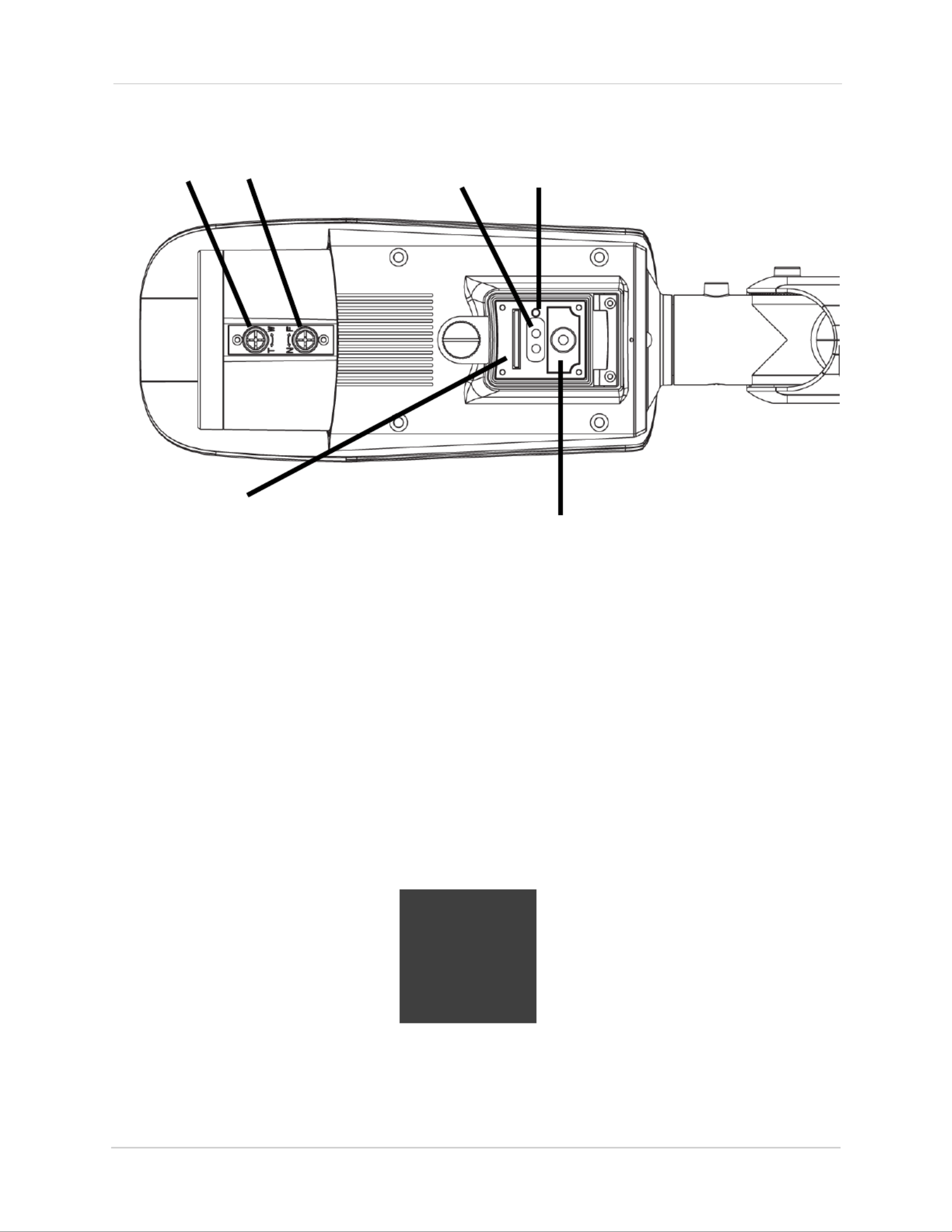
5. (Optional) Loosen the service compartment screw and open the service
compartment. The service compartment allows you to:
• Insert the included RCA-to-BNC test cable into the RCA output port and
connect the camera to a test monitor.
• Insert an SD card for local recording. To enable recording, you must format
the microSD card and configure microSD recording. For details, see “6.9.1
Record Directory” on page 40.
NOTE: The camera supports microSD cards up to a maximum size of 64GB.
SanDisk™ or Kingston™ brand microSD cards are recommended.
• Check the POWER/NET LED to determine network status. The LED glows
orange if power is connected and flashes when the camera is connected
to the network.
RCA-to-BNC
test cable
SD card slot
5
Status LED’s

10
Camera Installation
6. Loosen the three allen screws on the camera stand to adjust the camera
viewing angle as necessary. Tighten the allen screws when finished.
ABC
6
• Screw allows you to rotate the camera 360°, independent from the A
camera stand.
• Screw allows you to tilt the camera and camera stand 90°.B
• Screw allows you to rotate the camera and camera stand 360°.C
7. Use a Philip’s head screwdriver to adjust the camera zoom and focus as
needed.
Focus Zoom
7
8. Close the service compartment and firmly tighten the service
compartment screw.

11
Finding the Camera’s IP Address
4. FINDING THE CAMERA’S IP ADDRESS
Use the steps below to find the camera’s IP address and connect to the
camera over the local area network (LAN) using Syncro-V, UPnP on
Windows® 7, or Bonjour® in Mac OS®.
4.1 Finding the Camera’s IP Address Using Syncro-V
1. Install Syncro-V from the CD or from www.flirsecurity.com/pro.
Double-click the Syncro-V icon ( ) on the Desktop. The log in screen
appears.
2. User NameUnder and Password, enter the default Syncro-V user name
( ) and password ( ). Click .admin admin Login
Enter Admin
Enter Admin
Click Login

12
Finding the Camera’s IP Address
3. Syncro-V opens and scans the local network for connected cameras.
Detected camera IP addresses on the LAN appear in the Device List on
the left side of the screen with a icon.
Found camera
IP address
4. Click on a camera IP address in Device List to login.
5. Under User Name, enter the user name for the camera (default: admin).
Under , enter the password for the camera (default: ). Password admin
Click .Continue
Click Continue to login
Enter Camera User Name
(default: )admin
Enter Camera Password
(default: )admin

13
Finding the Camera’s IP Address
6. The camera appears under the camera IP address. Click and drag the
camera to the display grid to open it.
Click and drag the
camera to the display
grid to open it
NOTE: For detailed instructions on using Syncro-V, see the Syncro-V
manual on the CD.
4.2 Finding the Camera’s IP Address using UPnP in
Windows® 7
NOTE: To use this method, your router must support UPnP and the camera
and computer must be on the same network. UPnP is enabled in the camera
by default, and can be enabled/disabled using Syncro-V (check the Syncro-V
manual for details).

14
Finding the Camera’s IP Address
1. Click Start>Computer>Network. The camera’s IP address appears
under Network Infrastructure.
Network
Double-click to open
the camera
2. Double-click the camera to open it in your default browser.
3. User NameUnder and Pas sword, enter the camera’s User Name
(default: ) and Password (default: ) and click .admin admin Login
Enter Camera User Name (default: )admin
Enter Camera Password (default: )admin
Click Login
4.3 Finding the Camera’s IP Address using Bonjour in ®
Mac OS®
NOTE: To use this method, the camera and computer must be on the same
network. Bonjour® is enabled by default, and can be enabled/disabled
using Syncro-V (check the Syncro-V manual for details).
1. Open Safari® br owser and click the Bookmarks button ( ).

15
Finding the Camera’s IP Address
2. BonjourClick . The camera’s IP address appears in the Bonjour Devices
list.
3. Double-click the camera to open it in Safari®.
Bookmarks
button
Bonjour
Double-click the camera’s IP address
4. User NameUnder and Password, enter the camera’s User Name
(default: ) and Password (default: ) and click .admin admin Login
Enter Camera User Name (default: )admin
Enter Camera Password (default: )admin
Click Login
4.4 Finding the Camera IP using the BNC Test Cable
When the BNC test cable is connected to the camera, the IP address is shown
on the test monitor. The camera must be connected to power to use the BNC
test cable.
NOTE: The default IP addr ess of 192.168.0.120 is shown if the camera
cannot obtain an IP address from the router. Check the Ethernet/power
connections and router configuration.

16
Configuring Remote Connection
5. CONFIGURING REMOTE CONNECTION
Follow the steps below to configure your camera for connections over the
Internet using a web browser, Syncro-V, or other VMS software.
Step 1 of 6: Locate the camera’s local IP address:
• See “4. Finding the Camera’s IP Address” on page 11.
Step 2 of 6: Port Forward your router:
You need to enable port forwarding for the following ports on your router to
the camera’s local IP address:
• HTTP Port (default: )80
• Control Port (default: )30001
NOTE: If you are configuring multiple IP cameras for individual remote
access, you must change the ports for each camera. Two cameras cannot
use the same port number.
NOTE: Port forwarding the RTSP and RTMP ports is not necessary unless
your installation has special requirements.
There are two methods for port forwarding:
• You can manually port forward your router. See your router’s user manual
for details. An example of a port forwarding screen is shown below.
• Or, you can use the Auto Port Forwarding Wizard provided on the CD to
automatically configure the necessary ports. See the Auto Port
Forwarding manual on the CD for details.
HTTP
Control
80 80 100
100
30001 30001
17
Configuring Remote Connection
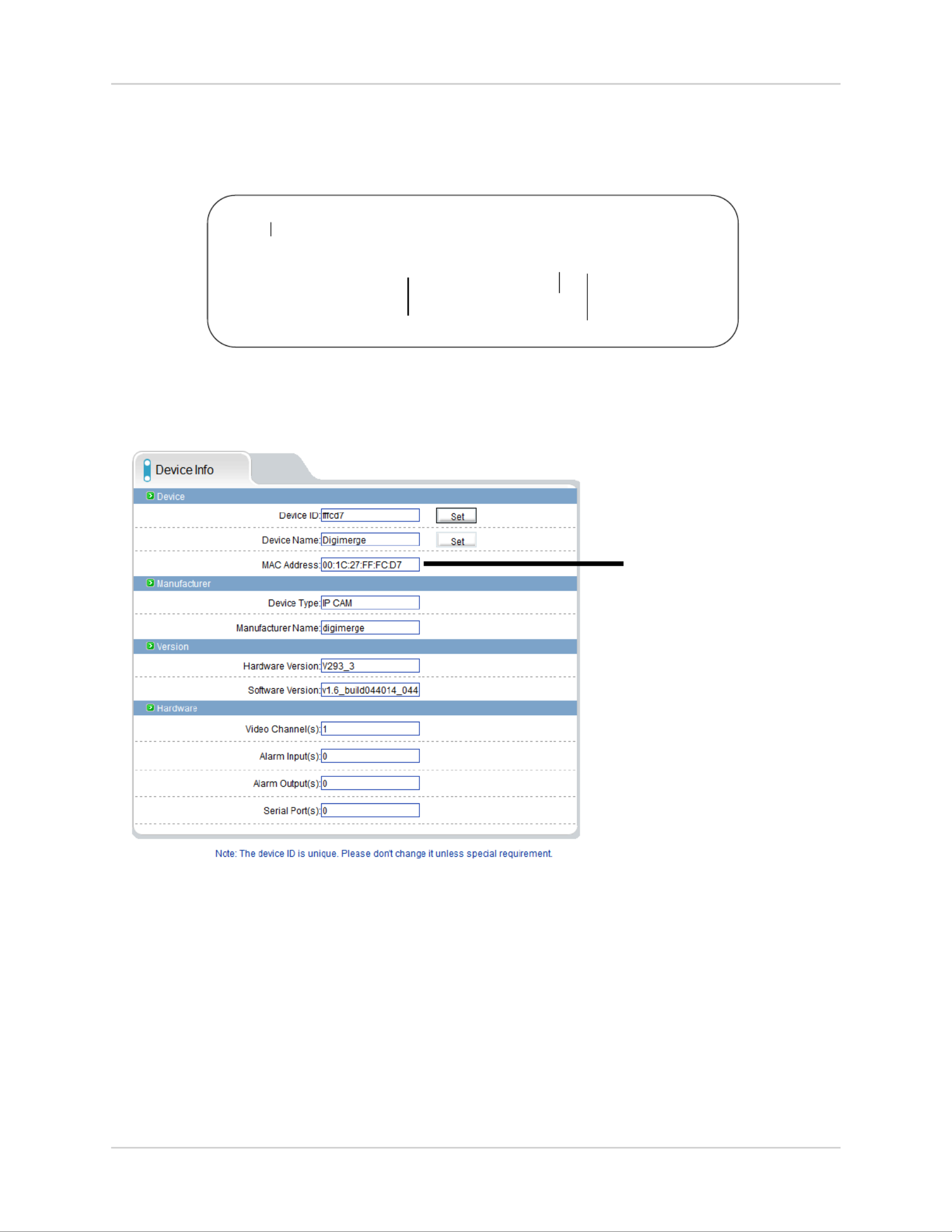
Step 3 of 6: Locate your camera’s MAC address:
1. Open a web browser and enter the camera’s IP address in the address
bar in the following format:
http:// :192.168.0.120 80
IP address Colon
HTTP port number
http://
2. User NameUnder and Password, enter the camera’s User Name
(default: ) and Password (default: ) and click .admin admin Login
3. Device Info MAC AddressClick and write down the .
MAC Address
Step 4 of 6: Register for FLIR DDNS:
FLIR offers a free DDNS service for use with your IP camera. A DDNS
account allows you to set up a web site address that points back to your local
network. The following outlines how to set up your free DDNS account.
NOTE: Your router must support UPnP to enable DDNS.
NOTE: You may use the same DDNS account for multiple IP cameras on
the same LAN.

18
Configuring Remote Connection
To setup your free FLIR DDNS account:
Click Create Account
1. In your browser, go to
http://ddns.myddns-flir.com and click Create
Account.
2. Complete the Account Information fields with
your personal information.
Enter personal information
3. Complete the System Information fields:
• Product License: Select your product model from the Product License
drop down menu.
• <Product Code> - <MAC Address>: Enter the camera’s MAC address
you recorded earlier.
• URL Request: Choose a URL for your DDNS connection (i.e. your name,
your company or business name, or anything of your choice).
4. Once the information has been entered, click .Create New Account
Select model number Enter MAC address
Choose URL Click Create New Account

19
Configuring Remote Connection
5. Your Account information will be sent to you at the email address you
used in Step 2. Record your Account Information below.
Domain Name:
User Name:
Password:
Step 5 of 6: Enable DDNS on the camera:
1. Enter the camera’s IP address in your web browser. Log in and then click
Network Service>DDNS.
2. Enable DDNSCheck .
3. Configure the following:
• Provider: FLIRDDNS Select .
• Domain Name: Domain Name Enter the you received from the
confirmation email you received after you created your DDNS account
(e.g. tomsmith.myddns-flir.com).
• User Name: User Name Enter the you received in the confirmation email.
• Password: Enter the Password you received in the confirmation email.
4. OKClick to save settings.
Step 6 of 6: Connect to the camera’s DDNS address:
1. Enter the camera’s DDNS address in your web browser in the following
format:
http:// :tomsmith.myddns-flir.com 80
DDNS address
Colon
HTTP port number
http://
2. User NameUnder and Password, enter the camera’s User Name
(default: ) and Password (default: ) and click . admin admin Login
Once you have logged into your system using your DDNS address, you can
connect to the IP camera from a remote location using a web browser,
Syncro-V, or other VMS software.

20
Configuring Remote Connection
5.1 Connecting to a DDNS address using Syncro-V
NOTE: Complete all the steps above before performing the following
method.
1. Open Syncro-V and click Device Manager>Video Device Manager.
2. ManagerClick . The Device Maintenance window opens.
Click Add Click Save
Enter the
camera’s
DDNS address
Control
Port
3. Device IPUnder , enter the from the confirmation email. Domain Name
For example, enter tomsmith.myddns-flir.com.
4. Control PUnder ort, enter the camera’s control port (default: ).30001
5. Devic(Optional) Under e Name, enter a name for the camera.
6. AddClick to add the camera to the Device List.
7. SaveClick to save changes. Click .OK

21
Configuring Remote Connection
8. Close Device Maintenance and Device Manager, and return to the Live
Video screen. The newly added camera will appear in Device List.
Found camera
NOTE: A icon is shown for all cameras outside of the LAN. This does
not affect your ability to connect to the camera remotely.
9. Click on the camera in Device List to login. Enter the User Name (default:
admin) and Password (default: ) and then click .admin Continue
Click Continue
Enter Camera User Name (default: )admin
Enter Camera Password (default: )admin
10.Click and drag the camera to a display grid screen to open it.
Click and drag the
camera to the display
grid to open it
NOTE: For detailed instructions on using Syncro-V, see the Syncro-V
manual on the CD.

22
Web Configuration
6. WEB CONFIGURATION
The camera includes a built-in web interface that can be accessed using a
web browser.
6.1 Supported Browsers
• Google Chrome, Mozilla Firefox, and Apple Safari® (via Adobe Flash
Player)
• Microsoft Internet Explorer® 7.0 or later, 32-bit version (via ActiveX®)
6.2 Chrome, Firefox, and Safari Setup
1. Connect the camera to your local network and find the camera’s IP
address. See “4. Finding the Camera’s IP Address” on page 11.
2. Open your browser and enter the camera’s IP address in the address bar
in the following format:
http:// :192.168.0.120 80
Camera IP address Colon
HTTP port number
http://
NOTE: You can also connect to the camera using a DDNS address (DDNS
setup and port forwarding required; see “5. Configuring Remote
Connection” on page 15 for details).
3. User NameUnder and Password, enter the camera’s User Name
(default: ) and Password (default: ) and click . admin admin Login
Enter Camera User Name (default: )admin
Enter Camera Password (default: )admin
Click Login

23
Web Configuration
4. The main screen for the camera web interface opens. From here you can
view and configure the camera. If you do not see video from the camera,
make sure your computer has the latest version of Adobe Flash Player
installed (visit http://www.adobe.com/ to download the latest version).
6.3 Internet Explorer® Setup
Step 1 of 2: Change Internet Explorer security settings for ActiveX®:
1. Open Internet Explorer and open the Security tab.
• Internet Explorer 8: Tools > Internet Options Click and select the
Security tab.
• Internet Explorer 9: Click > Internet Options and select the Security
tab.
2. Click Custom Level.
Click Custom level

24
Web Configuration
3. Download unsigned ActiveX controls PromptUnder , click
(recommended) or Enable.
Select Enable or Prompt under
Download unsigned ActiveX controls
Click OK
4. OK OKClick . Click again to save changes.
Step 2 of 2: Log into camera:
1. Connect the camera to your local network and find the camera’s IP
address. See “4. Finding the Camera’s IP Address” on page 11.
2. Enter the camera’s IP address in the address bar in the following format:
http:// :192.168.0.120 80
IP address Colon
HTTP port number
http://
NOTE: You can also connect to the camera using a DDNS address (DDNS
setup and port forwarding required; see “5. Configuring Remote
Connection” on page 15 for details).
3. User NameUnder and Password, enter the camera’s User Name
(default: ) and Password (default: ) and click . admin admin Login
Enter Camera User Name (default: )admin
Enter Camera Password (default: )admin
Click Login

25
Web Configuration
4. If your computer has Flash Player installed, the main screen for the
camera web interface opens. From here you can view and configure the
camera.
NOTE: The ActiveX plug-in may provide smoother video performance than
Flash Player. To use ActiveX, click the message above the video window.
Then click inside the video area, select Install this Add-on for all users on
this computer, and follow the prompts.
Install ActiveX plug-in
NOTE: If your computer does not have Flash Player installed, you will be
prompted to select if you would like to use ActiveX or Flash Player to connect
to the camera:
• Click to play live video with ActiveX control to reduce latency
(recommended): Uses an ActiveX plug-in to connect to the camera. To
install the plug-in, click on the video area, and select Install this Add-on
for all users on this computer, and follow the prompts.
• Click to download the latest version of Flash Player to play live video:
Opens a link to download Flash Player from Adobe’s website. After
completing the installation, restart your browser and reconnect to the
camera.
Select ActiveX or Flash Player

26
Web Configuration
6.4 Web Interface/Live Video Overview
The Live video page appears when you log into the camera. Live video
requires ActiveX® plugins or Adobe Flash Player.
6.4.1 Live Video Menu
You can right-click on the live video area to bring up the Live Video Menu.
Right-click on the video area to
open the Live Video Menu
Camera
configuration
menus
Click and drag to zoom in. Right-click and
select ZoomOut to zoom out.
Double-click inside window for full-screen
TIP: Select stream2 for better performance for remote
connections. Stream2 has a lower resolution than stream1.
Select Stream

27
Web Configuration
The Live Video Menu contains the following options:
• Full Screen: Open the video in full screen. Press ESC to exit full screen.
• Sensor Config: Configure the camera sensor settings. See “6.17 Sensor
Configuration” on page 55.
• Zoom in one level.ZoomIn:
• Zoom out one level.ZoomOut:
• Restore Panorama: Zoom out all the way.
6.4.2 Configuring Camera Settings
• Click the options on the left to configure camera settings. Setting options
are detailed in the remainder of this section.
TIP: Some sub-menus have a Reset button. This button will reset the
sub-menu options to factory defaults. You then have to click to save OK
changes.
Click to select
camera menus

28
Web Configuration
6.5 Device Info
The Device Info page shows information about your IP camera, such as the
Device Name (which appears in the Device List in Syncro-V), firmware
version, MAC address, and camera inputs and outputs. You can also
configure the Device Name for your camera.
ATTENTION: The device ID is unique. Do not change it unless your
installation has special requirements.
To configure the Device Name:
1. DeClick vice Info.
2. DeUnder vice Name, enter the desired device name and then click .Set

29
Web Configuration
6.6 Stream Configuration
The Stream Configuration page allows you to configure the camera’s video
streams. The camera supports three different video streams. This allows
you to have a high quality recording stream (stream1), a lower quality stream
(stream2) to preserve bandwidth for remote connections, and an MJPEG
stream for applications requiring MJPEG.
To configure video streaming settings:
1. StrClick eam Configuration Stream ID. Under , select the stream you
would like to configure.
2. Configure the following:
• Video Encode Type: Select the Video Encoding type for the stream.
Stream1 and stream2 can be configured for H.264 High Profile H.264 ,
Main Profile H.264 Base Profile MJPEG, or . Stream3 supports only.
• Audio Encode Type: Select the Audio Encoding type for the stream:
G711_ALAW G711_ULAW RAW_PCM, , or .
• Resolution: Select the resolution for the stream. Stream1 and stream3
can be set to . Stream2 can only be set to 1920x1080 or 640x360 640x360.

30
Web Configuration
• Frame Rate: Select the frame rate for the stream up to maximum of
30FPS 12FPS for stream1 or stream2 or for stream3.
NOTE: Frame rate may be automatically adjusted to account for bandwidth
limitations.
• I Frame interval: Select the interval for I frames: , , or . The default 1 2 3
value of should be used unless there are special requirements. The I 2
Frame interval does not apply to stream3.
• Bit Rate: For stream1 or stream2, select CBR (Constant Bit Rate) or VBR
(Variable Bit Rate). Enter the desired bit rate below in kbps. Stream3 only
supports VBR.
• Select the video quality between (lowest) and (highest).Quality: 1 9
TIP: A quality of 7 provides a good picture. It is not recommended to set a
high quality value with a small VBR bit rate.
3. OKClick to apply changes.
6.7 Device Configuration
Device Configuration contains the following sub-menus:
• Local Network
• Device Port
• Camera
• Date and Time
• OSD
• Microphone
• BNC Video Output
• Language
• Multicast (Not supported)
• Dome PTZ (Not supported)

31
Web Configuration
6.7.1 Local Network
The Local Network page shows the camera’s current IP address and
network parameters if DHCP is enabled. It also allows you to set a static IP
address for the camera (see below), set the networking parameters, and to
select IPv4 or IPv6.
NOTE: DHCP is enabled by default. When DHCP is enabled, the IP address
is shown under DHCP IP. Once you have completed the basic setup of the
camera, it is recommended to configure a static IP address. This will
prevent the camera IP address changing in the event of a power failure.
To configure the camera’s networking parameters:
1. Click Device Configuration>Local Network.
2. Under IP Protocol, select IPv4 or IPv6. If you would like to use IPv6, make
sure it is supported on your network. You may need to contact your
network administrator or ISP for details.
3. Select Device obtain an IP address automatically to use DHCP or Device
use the following IP address to set a static IP address for the camera. If
you are using a static IP address, configure the following:
• IP Address: Enter the IP address you would like to assign to the camera.
Make sure the IP address is available on your network.
• Subnet Mask: Enter the subnet mask.
• Preferred DNS Server/Alternate DNS Server: Enter desired DNS
servers.

32
Web Configuration
4. OKClick to save changes. The camera will restart with the new IP
address.
6.7.2 Device Port
The Device Port page (Device Configuration>Device Port) allows you to
configure the camera’s port configuration. The camera has the following
ports:
• Control port: The default is 30001. Enables video streaming.
• HTTP Port: The default is 80. Enables web access. Please note that if the
HTTP is port is anything other than 80, you must enter http:// before the
camera’s IP address and colon (:) and the HTTP port after the IP address
when connecting using an Internet browser (e.g. if the HTTP port is 85,
enter http://192.168.x.x:85).
• Default is 554. Only used for special applications requiring RTSP Port:
RTSP streaming.
• Default is 8080. Only used for special applications.RTMP Port:
NOTE: If you are configuring multiple IP cameras for individual remote
access (without an NVR or server), you must change all the ports for each
camera. Two cameras cannot use the same port number.
To change camera ports:
1. Configure the camera ports as required and then click .OK
2. Device Configuration>Device PortClick .

33
Web Configuration
6.7.3 Camera
The Camera page (Device Configuration>Camera) allows you to configure
the Channel Name, which appears on the camera OSD and the video system
frequency.
To change the Channel Name:
• Configure the as needed and then click the button Channel Name Set
next to Channel Name.
To change the video system frequency:
• Select the desired setting under Video System and then click the Set
button next to Source Resolution.
6.7.4 Date & Time
The Date & Time page allows you to configure the camera’s date and time.

34
Web Configuration
You can set the camera’s date and time the following ways:
The camera is configured to use NTP by default, but you
must set the time zone and Daylight Savings Time settings
to ensure accurate time. After a power failure, the camera
is configured to connect to an NTP server and automatically
update the time when power is restored. If using another
method to set the camera clock, time must be manually
updated after a power failure.
• Using an NTP server (recommended)
• Using your computer’s system time
• Manually
To set the camera’s date and time using an NTP server:
1. Click Device Configuration>Date & Time.
2. Under Time Zone, select your time zone.
3. If your region observes daylight savings time, check Adjust clock for
daylight saving changes.
• Under Start and End, select the start and end times for daylight savings.
4. Next to Current PC Time, click Apply.
To sync the camera’s date and time to your computer’s system time:
1. Click Device Configuration>Date & Time.
2. Un-check Enable NTP and click Apply at the bottom of the screen.
3. Time ZoneUnder , select your time zone.
4. If your region observes daylight savings time, check Adjust clock for
daylight saving changes.
• Under Start and End, select the start and end times for daylight savings.
5. ApplyClick next to Current Computer Time. The Current Device Time
updates.
To set the camera’s date and time manually:
1. Click Device Configuration>Date & Time.
2. Under Time Zone, select your time zone.

35
Web Configuration
3. Enable NTP ApplyUn-check and click at the bottom of the screen.
4. If your region observes daylight savings time, check Adjust clock for
daylight saving changes.
• Under Start and End, select the start and end times for daylight savings.
5. Set ManuallyClick , and use the on-screen calendar to set the time and
date.
6. ApplyClick . The camera updates to the newly entered time.
6.7.5 OSD
The OSD page allows you to configure the camera’s on-screen display text.
To configure the camera OSD:
1. DeClick vice Configuration>OSD.
2. Check the following options to enable OSD text:
• Device Name: Display the Device Name.
• Channel ID: Show the channel ID number.
• Channel Name: Show the name of the channel set in the Camera menu.
• Show the date and time on the OSD. Select the desired date and Time:
time format under Time Format.

36
Web Configuration
• Custom: Create a custom OSD message. Enter the custom OSD text under
Custom OSD.
3. Enter the desired and for enabled OSD messages. Text on Row Column
row 0 is shown at the top of the screen, and moves down as the row
number increases. Text on column 0 is shown on the left side of the
screen, and moves right as the column number increases.
Row 0
Column 0
Row #
increases
Column # increases
4. OK Click to update the camera OSD.
6.7.6 Microphone
Device Name
Channel ID
Time
Custom
Channel Name

37
Web Configuration
Configure microphone settings for listen-in audio. Self-powered
microphone required (not included).
To configure microphone settings:
1. DeClick vice Configuration>Microphone.
2. Check Enable Microphone to enable listen-in audio or un-check to
disable.
3. Microphone VUnder olume, select the volume for the microphone
between .1~100
4. OKClick to save changes.
6.7.7 BNC Video Output
Under BNC Output (Device Configuration>BNC Ouput), select On to enable
analog output or to disable and click .Off OK
6.7.8 Language
Change the language for the camera OSD display (e.g. time and date display)
and email alarms. Supported languages are English, Polish, Russian, and
Chinese.
38
Web Configuration
To change the language for the OSD and email alarms:
1. Device Configuration>LanguageClick .
2. Under Language, select the desired language then click to save OK
changes.
6.8 Alarm Configuration
Alarm Configuration contains the following sub-menus:
• Disk Alarm
• Motion Alarm
• Alarm I/O (Not supported)
• I/O Alarm Linkage (Not supported)
• Alarm Setting (Not supported)
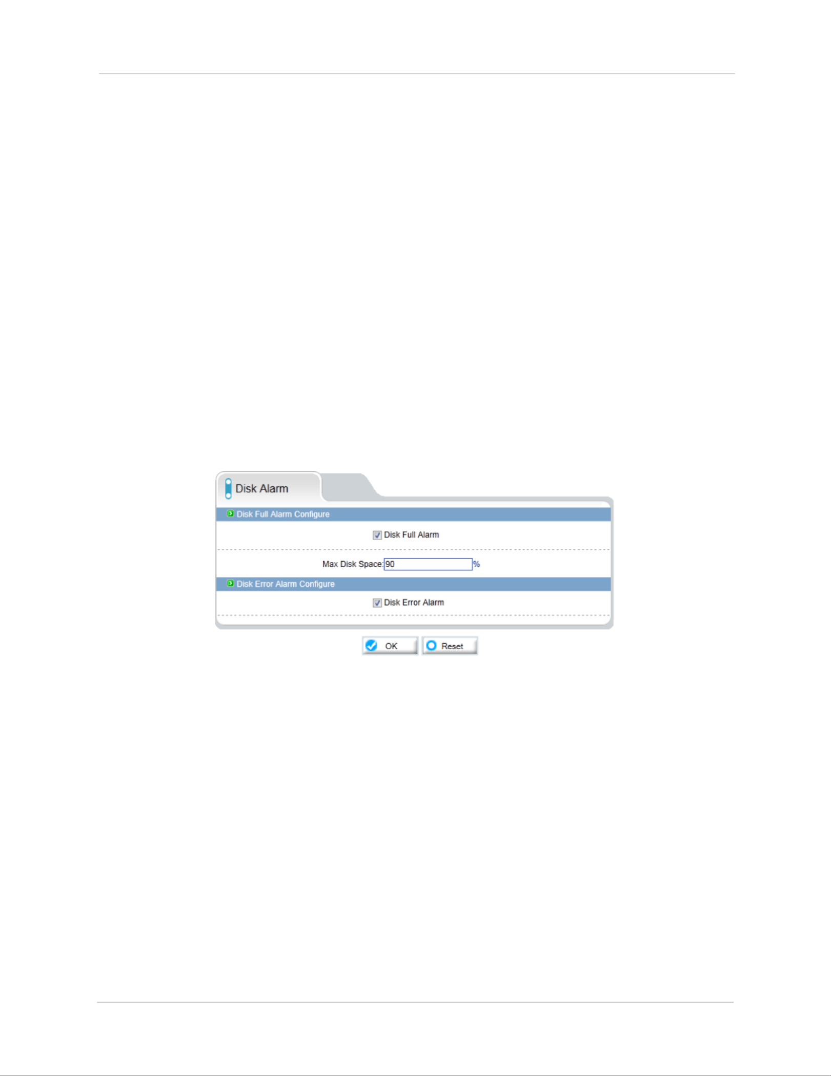
6.8.1 Disk Alarm
The Disk Alarm page allows you to configure alarms if there is an issue with
the recording disk. You can configure a Disk Full Alarm or a Disk Error
Alarm. A Disk Full Alarm triggers an alarm when the recording disk is full or
exceeds a certain percentage. A Disk Error Alarm triggers an alarm if there
is an error accessing or writing to the recording disk.
Alarms can be viewed using the Alarm Manager in Syncro-V (see the
Syncro-V manual on the CD for details).
To configure Disk Alarms:
1. Alarm ConfigurClick ation>Disk Alarm.
2. Disk Full AlarmCheck to enable Disk Full Alarms.

39
Web Configuration
3. Under Max Disk Space, enter the disk full percentage that will trigger an
alarm (e.g. a Disk Full Alarm will be triggered when the recording disk is
80% full).
4. Disk ErrCheck or Alarm to enable Disk Error Alarms.
5. OKClick .
6.8.2 Motion Alarm
The Motion alarm page allows you to configure camera motion detection
alarm settings. You must enable motion detection to use local (e.g. microSD/
SD card or FTP recording) motion detection recording. For instructions on
setting up local recording, see “6.9 Local Record” on page 39. For details on
motion recording using Syncro-V, see the Syncro-V manual on CD.
To configure motion detection:
1. Alarm Configuration>Motion AlarmClick .
2. EnableCheck under Motion Parameter.
3. ScheduleClick to configure a motion detection schedule. The Schedule
Time Setting menu opens.
NOTE: If the Schedule Time Setting menu does not open, disable any popup
blockers.

40
Web Configuration
4. Configure the weekly schedule. The schedule is divided into 3 periods,
and motion detection will be enabled in all times during all 3 periods.
5. Motion AreaClick , and configure up to 8 motion detection areas:
• Select Area Motion Area Mask or to configure motion detection areas.
• Area Motion allows you to select areas where motion detection is enabled.
• Area Mask enables the entire image for motion detection, and allows you
to select areas to disable motion detection.
• Right-click to delete the last created area.
6. Under Sensitivity, select the sensitivity for motion detection: , Low
Medium High, or .
7. OKClick to save your settings.
6.9 Local Record
Local Record contains the following sub-menus:
• Record Policy
• Record Directory

41
Web Configuration
6.9.1 Record Directory
Record Directory allows you to configure the microSD/SD memory card,
NAS, and FTP storage locations. It also allows you format the microSD/SD
card.
IMPORTANT: You must format the microSD/SD card using the camera
before you can record to it.
To format the microSD/SD card to enable recording:
NOTE: Formatting the microSD/SD card erases all data on the card.
1. Click Local Record>Record Directory.
2. Make sure to disable all recording types in Record Policy before
formatting the microSD/SD card. See “6.9.2 Record Policy” on page 45.
3. Disk NameUnder , select SD1.
4. ModifyClick . The Record Disk Path menu opens.
Select SD1
Click Modify

42
Web Configuration
5. EnableCheck .
Click Format
Check Enable
6. Under File System, select SDVideo (recommended) or .Ext3
7. FormatClick . A window will appear to show the status of the formatting.
Wait for the formatting to complete and then click .OK
NOTE: If the Record Disk Path menu does not open or formatting does not
occur, disable any popup blockers.
To configure FTP storage location:
1. Click Local Record>Record Directory.
2. Disk NameUnder , select ftp.
Select ftp
Click Modify
3. ModifyClick . The Record Disk Path opens.
4. EnableCheck .

43
Web Configuration
5. Configure the following:
Check Enable
Configure FTP
server information
Click OK
• Enter the FTP server address.IP:
• Enter the FTP port number.Port:
• Accounts: Enter the FTP account user name.
• Password/Confirm Password: Enter the FTP password.
• Free Space: Enter the amount of space (in MB) you would like to make
available on the FTP server for recording.
6. OKClick .
7. Set up recording using the Record Policy sub-menu (see “6.9.1 Record
Directory” on page 40). To access your recordings, use Syncro-V or
manually access your FTP server.
NOTE: On the Record Directory page, Status will be OK when FTP is selected
if FTP is accessible and all settings have been entered correctly.
Status OK

44
Web Configuration
To configure a NAS storage location:
1. Click Local Record>Record Directory.
2. Disk NameUnder , select //.
Select //
Click Modify
3. ModifyClick . The Record Disk Path menu opens.
4. Configure the following:
• Enter the IP address of the NAS.IP:
• Enter the NAS folder where video files will be saved. NAS folder Path:
must be located directly under the root folder of the NAS (e.g. /public).
• Accounts: Enter the account user name for the NAS.

45
Web Configuration
• Password/Confirm Password: Enter the account password for the NAS.
• File System: Enter the NAS file system ( or ).cifs nfs
• Use All Space: Check to enable the camera to record until the NAS is full.
Uncheck to limit the amount of space the camera can record on and enter
the amount of space (in MB) available to the camera under Free Space.
5. OKClick .
6. Set up recording using the Record Policy sub-menu (see “6.9.1 Record
Directory” on page 40). To access your recordings, use Syncro-V or
manually access your NAS device.
NOTE: On the Record Directory page, Status will be OK when NAS is
selected if NAS is accessible and all settings have been entered correctly.
Status OK

46
Web Configuration
6.9.2 Record Policy
The Record Policy menu allows you to set the microSD/SD memory card,
NAS, and FTP recording parameters. Once configured, the device can record
video directly to a microSD/SD card, NAS, and FTP.
To enable recording to microSD/NAS/FTP:
1. LocClick al Record>Record Policy.
2. Configure recording storage locations in the Record Directory sub-menu.
See “6.9.1 Record Directory” on page 40.
NOTE: The camera will simultaneously record to all storage locations that
have been enabled in Record Directory.
3. To enable scheduled or continuous recording, check Enable under
Schedule Record. Select 7*24 H Record to record video continuously at
all times, or, select Schedule Record to create a schedule for recording.
• If you select Schedule Record, click Schedule and configure recording
times. The schedule is divided into 3 periods, and the camera will record

47
Web Configuration
during all selected times in all 3 periods. Click when finished OK
configuring the recording schedule.
4. To enable Motion Alarm Recording, check Enable Alarm Record under .
Configure Pre-recording Post-recording Motion and times. Check
Alarm, Channel.
5. StrUnder eam, select the stream to use for recording. Stream1 is
recommended if you want to record high quality video, stream2 is
recommended if you want to save bandwidth or storage space.
6. RecCheck ord Audio to enable audio recording.
7. Under Storage Rule, select Cycle Write to enable the camera to
overwrite the oldest recorded data once the available space in the
storage location is filled. Or, select Save Days to save video for a set
number of days and enter the desired. Note that you Number of Days
must have sufficient storage space to save the number of days entered.
8. OKClick to save changes.
NOTE: To view video from the SD/microSD card, FTP, or NAS, use Syncro-V’s
playback features, see the Syncro-V manual on the CD for details. You can
access video saved to FTP or NAS by manually accessing your FTP server
or NAS device.

48
Web Configuration
6.10 Privacy Masking
The Privacy Masking menu allows you to create up to 5 privacy areas that will
not appear in recordings. You can cover up to 8% of the total image area.
To configure privacy areas:
1. PrivClick acy Masking.
2. EnablCheck e Privacy Masking.
3. Click and drag inside the video area to configure privacy areas. Privacy
areas will be shown as green rectangles. Right-click to delete the last
created area.
4. OKClick . An error message appears if the masks configured exceed 8%
of the total image area.
6.11 Network Service
Network Service contains the following sub-menus:
• DDNS
• PPPoE (Not supported)
Privacy area

49
Web Configuration
6.11.1 DDNS
The DDNS sub-menu allows you to configure DDNS settings. Before
configuring DDNS settings, you must register the camera for a free FLIR
DDNS account (see “5. Configuring Remote Connection” on page 15).
To configure DDNS settings:
1. NetwClick ork Service>DDNS.
2. Enable DDNSCheck .
3. Configure the following:
• Provider: FLIRDDNS Select .
• Domain Name: Domain Name Enter the you received from the
confirmation email you received after you created your DDNS account.
NOTE: Connect to your camera using a web browser by entering , http://
the , , and then the . For example, if the Domain Name colon HTTP port
Domain Name is tomsmith.myddns-flir.com, use the address
http://tomsmith.myddns-flir.com:80.
• User Name: User Name Enter the you received in the confirmation email.
• Password: Enter the Password you received in the confirmation email.
4. OKClick to save settings.
6.12 Service Center
Service Center contains the following sub-menus:
• SMTP
• Alarm Center (not supported)

50
Web Configuration
6.12.1 SMTP (Email Alert Setup)
The SMTP sub-menu allows you to configure email alerts when motion
alarms occur. Email alerts will include a .jpg snapshot attachment.
Before setting up email alerts you must configure the following:
• Motion alarms must be enabled before the camera will send email alerts.
See “6.8.2 Motion Alarm” on page 38.
• A static IP address must be configured for the camera and DNS servers
must be entered. See “6.7.1 Local Network” on page 30.
To enable email alerts:
1. Click Service Center>SMTP.
2. Check Enable SMTP.
3. Configure the following:
• SMTP Server Address: Enter the address for your SMTP server.
• SMTP Server Port: Enter your server’s SMTP port number.
• Enter the SMTP account user name.User Name:
• Password: Enter the SMTP account password.

51
Web Configuration
• Sender E-mail Address: Enter the email address that will be used to send
email alerts.
• Recipient E-mail Address 1~5: Enter up to 5 email addresses that will
receive email alerts.
• Attachment Image Quality: Select the quality of the image attachments:
High Mid Low, , or .
• Transport Mode: Select the encryption type used by the server (SSL or
STARTTLS) or select No encrypted if your server does not use encryption.
4. OKClick to save your settings. Click to send a test email Send testmail
alert.
6.13 Privilege Manager
Privilege Manager allows you to configure user accounts and user groups.
Privilege Manager contains the following sub-menus:
• Group
• User
6.13.1 Group

52
Web Configuration
The Group page (Privilege>Group) allows you to manage permissions for
user groups. Users obtain permissions from their group. The Administrators
group contains all permissions and cannot be deleted or edited.
To add a user group:
1. AddClick . The Add Group menu appears.
NOTE: If the Add Group menu does not appear, disable any popup blockers.
2. Enter a name for the user group and click .OK
Enter a group
name and click OK
3. GroupUnder , select the new group.
4. Check the permissions you would like to apply to this user group. You can
check or un-check Select All to select all or no permissions.
5. OKClick to save your new user group.
To modify a user group:
1. GrUnder oup, select the group you would like to modify.
2. ModifyClick to change the group name if needed, enter a new group
name and click .OK
3. Change permissions as needed and click OK.
To delete a user group:
1. Click Delete. The Delete Group menu appears.
NOTE: If the Delete Group menu does not appear, disable any popup
blockers.
2. Select the group you would like to delete and click Delete.
53
Web Configuration
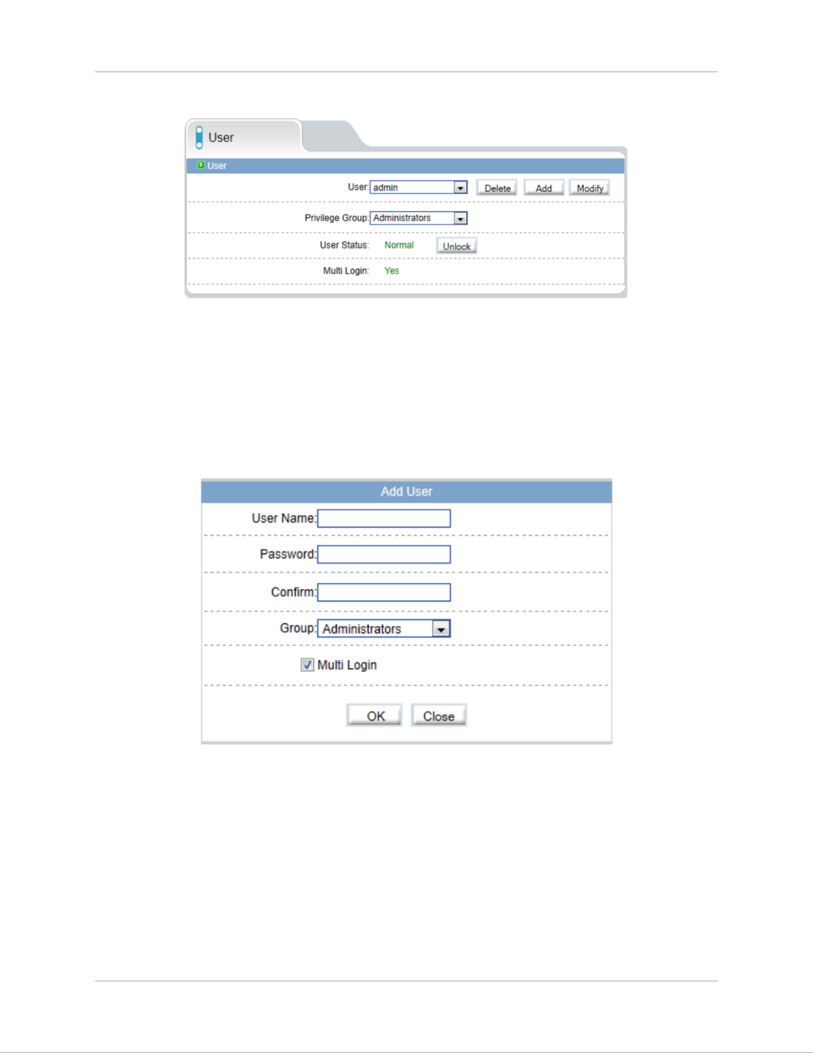
6.13.2 User
The User page (Privilege>User) allows you to manage user accounts. User
accounts receive privileges based on their group. The admin account is the
system administrator, and has full access to all functions.
To add a user account:
1. AddClick . The Add User window appears.
NOTE: If the Add User menu does not appear, disable any popup blockers.
2. User NameEnter a and Password for the account and repeat the
password under .Confirm
3. GroupUnder , select the desired user group for this account.
4. Multi LoginCheck to allow the user account to log into the IP camera
from multiple location simultaneously or un-check to limit the account to
a single location at a time.
5. OKClick to save the new user account.

54
Web Configuration
To modify a user account:
1. Select the user account under and click User Modify.
2. Modify the account details as needed and click .OK
To delete a user account:
• Under User, select the user account and click Delete. Click OK to confirm.
6.13.3 Unlocking User Accounts
The admin account is the only account that can unlock user accounts that
have been locked out. User accounts are locked out if the wrong password is
entered 3 or more times.
To unlock a user account:
1. Login to the camera as admin.
2. Click Privilege Manager>User.
Select the
user
Click Unlock
3. UserUnder , select the locked user account.
4. UnlockClick to unlock the account.
6.14 Protocol
Protocol contains the following sub-menus:
• Protocol
• Security (Not supported)
NOTE: Do not check User Verification in the Security sub-menu, as it may
block ONVIF software from detecting the camera.

55
Web Configuration
6.14.1 Protocol
The Protocol page (Protocol>Protocol) allows you to view ONVIF protocol
settings.
6.15 Device Restart
Click Device Restart. Click Restart then click to restart the camera.OK
6.16 Default Settings
Click Default Settings. Click Restore then click OK to restore the camera to
factory default settings. The camera will reboot.
56
Web Configuration
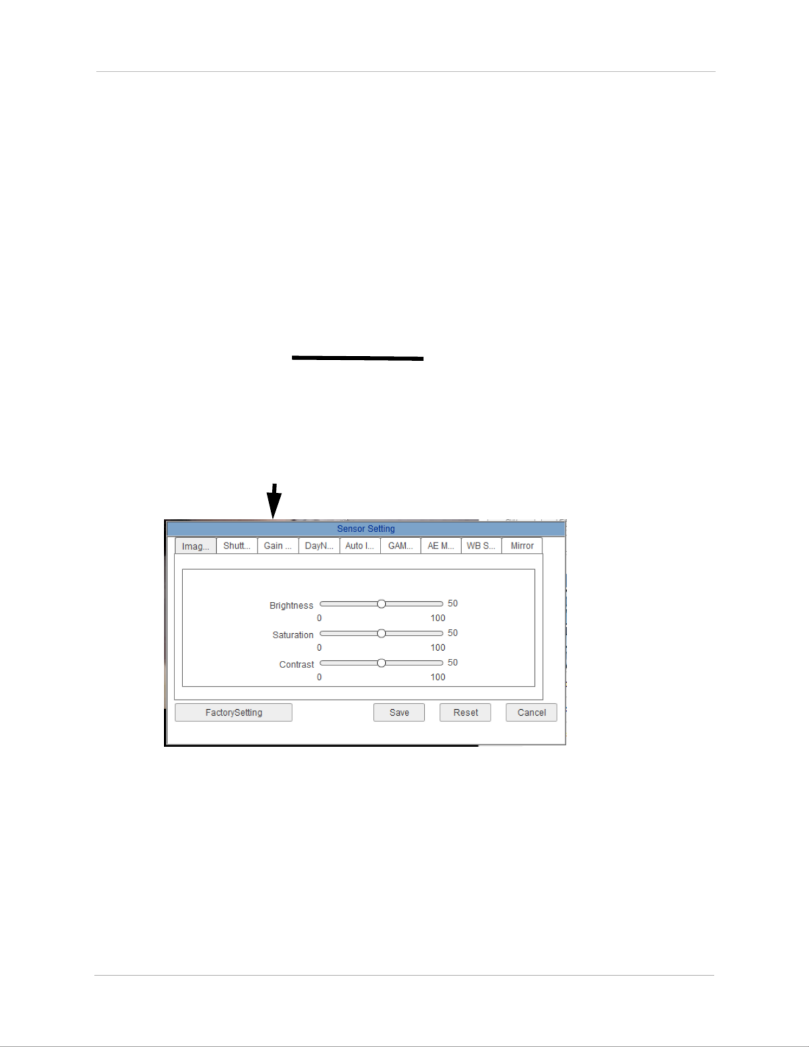
6.17 Sensor Configuration
The Sensor Configuration menu is used to adjust camera image settings.
To configure camera image settings using the Sensor Configuration menu:
• Log into the camera using a web browser, and from the Live Video page,
right-click on the video area and select .Sensor Config
• Click Save to save setting changes.
• Click to revert to the last saved changes.Reset
• Click Factory Setting to revert all camera sensor settings to factory
defaults.
• Click Cancel to exit.
TIP: Hold the mouse over the tabs to see the full name of the tab.
Right-click in the video area
and select Sensor Config
57
Web Configuration
6.17.1 Image Adjust
Adjust the Brightness, Saturation, and Contrast settings for the image.
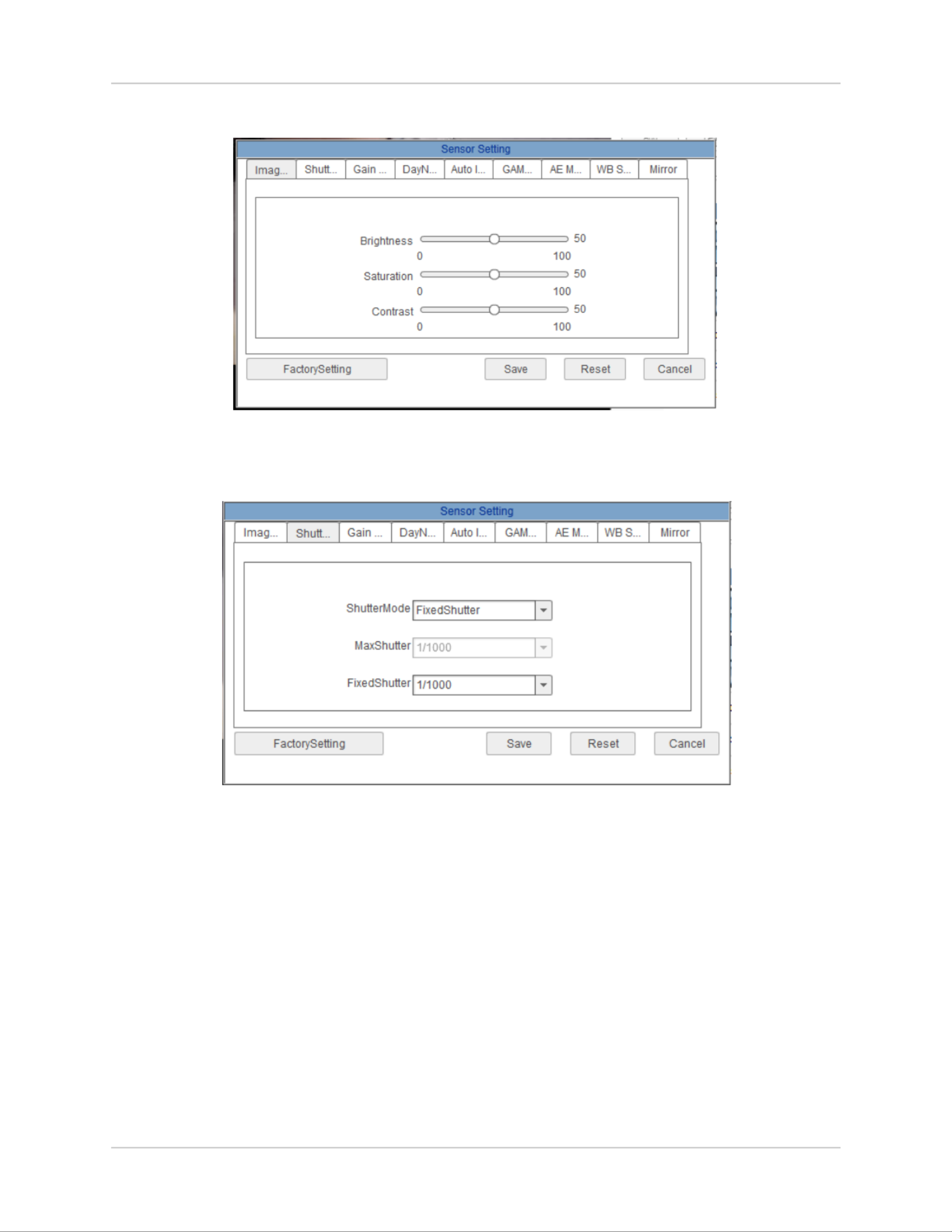
6.17.2 Shutter Control
Adjust the camera shutter settings.
• Select or ShutterMode: AutoShutter FixedShutter.
• MaxShutter: Sets the upper limit of the shutter speed when AutoShutter
is selected.
• FixedShutter: Sets the shutter speed when FixedShutter is selected.
Termékspecifikációk
| Márka: | Flir |
| Kategória: | Térfigyelő kamera |
| Modell: | SyncroIP DNB14UX2 |
Szüksége van segítségre?
Ha segítségre van szüksége Flir SyncroIP DNB14UX2, tegyen fel kérdést alább, és más felhasználók válaszolnak Önnek
Útmutatók Térfigyelő kamera Flir

13 Január 2025
2 Október 2024
28 Szeptember 2024
14 Szeptember 2024
9 Szeptember 2024
9 Szeptember 2024
2 Szeptember 2024
2 Szeptember 2024
26 Augusztus 2024
25 Augusztus 2024
Útmutatók Térfigyelő kamera
- Térfigyelő kamera Samsung
- Térfigyelő kamera Sony
- Térfigyelő kamera August
- Térfigyelő kamera Nedis
- Térfigyelő kamera Grundig
- Térfigyelő kamera Philips
- Térfigyelő kamera Pioneer
- Térfigyelő kamera Reolink
- Térfigyelő kamera Garmin
- Térfigyelő kamera Bosch
- Térfigyelő kamera Panasonic
- Térfigyelő kamera Canon
- Térfigyelő kamera JVC
- Térfigyelő kamera Evolveo
- Térfigyelő kamera Toshiba
- Térfigyelő kamera Ubiquiti Networks
- Térfigyelő kamera TP-Link
- Térfigyelő kamera Emos
- Térfigyelő kamera Motorola
- Térfigyelő kamera LogiLink
- Térfigyelő kamera Digitus
- Térfigyelő kamera Zebra
- Térfigyelő kamera Xiaomi
- Térfigyelő kamera TRENDnet
- Térfigyelő kamera EZVIZ
- Térfigyelő kamera Boss
- Térfigyelő kamera Crestron
- Térfigyelő kamera ORNO
- Térfigyelő kamera Strong
- Térfigyelő kamera Gigaset
- Térfigyelő kamera MEE Audio
- Térfigyelő kamera Conceptronic
- Térfigyelő kamera Thomson
- Térfigyelő kamera Technaxx
- Térfigyelő kamera Speco Technologies
- Térfigyelő kamera Ricoh
- Térfigyelő kamera Hikvision
- Térfigyelő kamera Netgear
- Térfigyelő kamera Asus
- Térfigyelő kamera Vtech
- Térfigyelő kamera Rollei
- Térfigyelő kamera Hama
- Térfigyelő kamera Mitsubishi
- Térfigyelő kamera Synology
- Térfigyelő kamera Avidsen
- Térfigyelő kamera Raymarine
- Térfigyelő kamera DSC
- Térfigyelő kamera Kodak
- Térfigyelő kamera Ring
- Térfigyelő kamera V-TAC
- Térfigyelő kamera ZyXEL
- Térfigyelő kamera Logitech
- Térfigyelő kamera Dahua Technology
- Térfigyelő kamera Withings
- Térfigyelő kamera Denver
- Térfigyelő kamera First Alert
- Térfigyelő kamera Minox
- Térfigyelő kamera Trevi
- Térfigyelő kamera DiO
- Térfigyelő kamera Planet
- Térfigyelő kamera Burg Wächter
- Térfigyelő kamera Ernitec
- Térfigyelő kamera Tenda
- Térfigyelő kamera Qian
- Térfigyelő kamera Aluratek
- Térfigyelő kamera Extech
- Térfigyelő kamera Gembird
- Térfigyelő kamera Cisco
- Térfigyelő kamera Niceboy
- Térfigyelő kamera SPC
- Térfigyelő kamera Bea-fon
- Térfigyelő kamera Powerfix
- Térfigyelő kamera Edimax
- Térfigyelő kamera Eufy
- Térfigyelő kamera APC
- Térfigyelő kamera Overmax
- Térfigyelő kamera Lorex
- Térfigyelő kamera Foscam
- Térfigyelő kamera Manhattan
- Térfigyelő kamera Kogan
- Térfigyelő kamera Alecto
- Térfigyelő kamera Honeywell
- Térfigyelő kamera EnGenius
- Térfigyelő kamera Imou
- Térfigyelő kamera Marshall
- Térfigyelő kamera Acme
- Térfigyelő kamera Furrion
- Térfigyelő kamera Velleman
- Térfigyelő kamera Western Digital
- Térfigyelő kamera Grandstream
- Térfigyelő kamera D-Link
- Térfigyelő kamera Avanti
- Térfigyelő kamera Milesight
- Térfigyelő kamera Monacor
- Térfigyelő kamera IDIS
- Térfigyelő kamera Epiphan
- Térfigyelő kamera ION
- Térfigyelő kamera Blaupunkt
- Térfigyelő kamera Chacon
- Térfigyelő kamera Elro
- Térfigyelő kamera GVI Security
- Térfigyelő kamera Moxa
- Térfigyelő kamera Olympia
- Térfigyelő kamera Delta Dore
- Térfigyelő kamera ZKTeco
- Térfigyelő kamera Abus
- Térfigyelő kamera Vivotek
- Térfigyelő kamera AG Neovo
- Térfigyelő kamera Arlo
- Térfigyelő kamera Trust
- Térfigyelő kamera Konig
- Térfigyelő kamera Marmitek
- Térfigyelő kamera Stabo
- Térfigyelő kamera Pyle
- Térfigyelő kamera Lumens
- Térfigyelő kamera AVer
- Térfigyelő kamera AVMATRIX
- Térfigyelő kamera Sanyo
- Térfigyelő kamera DataVideo
- Térfigyelő kamera CRUX
- Térfigyelő kamera Atlona
- Térfigyelő kamera Schneider
- Térfigyelő kamera Lindy
- Térfigyelő kamera Uniden
- Térfigyelő kamera Quantum
- Térfigyelő kamera Marshall Electronics
- Térfigyelő kamera Trebs
- Térfigyelő kamera M-e
- Térfigyelő kamera Provision-ISR
- Térfigyelő kamera Somfy
- Térfigyelő kamera AViPAS
- Térfigyelő kamera Axis
- Térfigyelő kamera Brilliant
- Térfigyelő kamera Orion
- Térfigyelő kamera EverFocus
- Térfigyelő kamera SereneLife
- Térfigyelő kamera I3International
- Térfigyelő kamera Equip
- Térfigyelő kamera Genius
- Térfigyelő kamera Valueline
- Térfigyelő kamera Swann
- Térfigyelő kamera Adj
- Térfigyelő kamera Anker
- Térfigyelő kamera Genie
- Térfigyelő kamera Petcube
- Térfigyelő kamera ClearView
- Térfigyelő kamera Sitecom
- Térfigyelő kamera ACTi
- Térfigyelő kamera Schwaiger
- Térfigyelő kamera Elmo
- Térfigyelő kamera Vitek
- Térfigyelő kamera Alfatron
- Térfigyelő kamera Laserliner
- Térfigyelő kamera Smartwares
- Térfigyelő kamera REVO
- Térfigyelő kamera Belkin
- Térfigyelő kamera KJB Security Products
- Térfigyelő kamera Kramer
- Térfigyelő kamera BZBGear
- Térfigyelő kamera BirdDog
- Térfigyelő kamera Allnet
- Térfigyelő kamera Aldi
- Térfigyelő kamera Airlive
- Térfigyelő kamera Aritech
- Térfigyelő kamera Flamingo
- Térfigyelő kamera Yale
- Térfigyelő kamera Caliber
- Térfigyelő kamera Eminent
- Térfigyelő kamera Exibel
- Térfigyelő kamera Fortinet
- Térfigyelő kamera KlikaanKlikuit
- Térfigyelő kamera Maginon
- Térfigyelő kamera Profile
- Térfigyelő kamera Marquant
- Térfigyelő kamera Ednet
- Térfigyelő kamera AVerMedia
- Térfigyelő kamera Steren
- Térfigyelő kamera Perel
- Térfigyelő kamera Netis
- Térfigyelő kamera Buffalo
- Térfigyelő kamera GeoVision
- Térfigyelő kamera Nest
- Térfigyelő kamera LevelOne
- Térfigyelő kamera Siedle
- Térfigyelő kamera Hive
- Térfigyelő kamera Netatmo
- Térfigyelő kamera Switel
- Térfigyelő kamera InFocus
- Térfigyelő kamera Hombli
- Térfigyelő kamera Clas Ohlson
- Térfigyelő kamera Naxa
- Térfigyelő kamera BRK
- Térfigyelő kamera EVE
- Térfigyelő kamera Waeco
- Térfigyelő kamera QSC
- Térfigyelő kamera Xavax
- Térfigyelő kamera Vaddio
- Térfigyelő kamera Gira
- Térfigyelő kamera Jung
- Térfigyelő kamera Interlogix
- Térfigyelő kamera Boyo
- Térfigyelő kamera IC Intracom
- Térfigyelő kamera Adesso
- Térfigyelő kamera Satel
- Térfigyelő kamera POSline
- Térfigyelő kamera Notifier
- Térfigyelő kamera Hawking Technologies
- Térfigyelő kamera Lanberg
- Térfigyelő kamera Friedland
- Térfigyelő kamera Nexxt
- Térfigyelő kamera Monoprice
- Térfigyelő kamera Watec
- Térfigyelő kamera Beafon
- Térfigyelő kamera Chuango
- Térfigyelő kamera ETiger
- Térfigyelő kamera Videcon
- Térfigyelő kamera INSTAR
- Térfigyelő kamera Advantech
- Térfigyelő kamera Digital Watchdog
- Térfigyelő kamera Ferguson
- Térfigyelő kamera Ganz
- Térfigyelő kamera Kwikset
- Térfigyelő kamera Intellinet
- Térfigyelő kamera ClearOne
- Térfigyelő kamera Ebode
- Térfigyelő kamera Oplink
- Térfigyelő kamera Kerbl
- Térfigyelő kamera Dorr
- Térfigyelő kamera Sonic Alert
- Térfigyelő kamera Linear PRO Access
- Térfigyelő kamera Summer Infant
- Térfigyelő kamera SMC
- Térfigyelő kamera Topica
- Térfigyelő kamera Iiquu
- Térfigyelő kamera Verint
- Térfigyelő kamera Brinno
- Térfigyelő kamera Rostra
- Térfigyelő kamera Caddx
- Térfigyelő kamera Spyclops
- Térfigyelő kamera EKO
- Térfigyelő kamera Inovonics
- Térfigyelő kamera Kguard
- Térfigyelő kamera Woonveilig
- Térfigyelő kamera Mobi
- Térfigyelő kamera Surveon
- Térfigyelő kamera Hollyland
- Térfigyelő kamera Epcom
- Térfigyelő kamera Indexa
- Térfigyelő kamera Lutec
- Térfigyelő kamera Whistler
- Térfigyelő kamera Hanwha
- Térfigyelő kamera VideoComm
- Térfigyelő kamera IMILAB
- Térfigyelő kamera 3xLOGIC
- Térfigyelő kamera Pelco
- Térfigyelő kamera Leviton
- Térfigyelő kamera EtiamPro
- Térfigyelő kamera Inkovideo
- Térfigyelő kamera Pentatech
- Térfigyelő kamera Weldex
- Térfigyelő kamera SecurityMan
- Térfigyelő kamera Canyon
- Térfigyelő kamera CNB Technology
- Térfigyelő kamera Tapo
- Térfigyelő kamera Aigis
- Térfigyelő kamera Exacq
- Térfigyelő kamera Brickcom
- Térfigyelő kamera Laxihub
- Térfigyelő kamera Securetech
- Térfigyelő kamera EFB Elektronik
- Térfigyelő kamera NetMedia
- Térfigyelő kamera Videotec
- Térfigyelő kamera Illustra
- Térfigyelő kamera Nivian
- Térfigyelő kamera Arenti
- Térfigyelő kamera E-bench
- Térfigyelő kamera Blow
- Térfigyelő kamera Syscom
- Térfigyelő kamera Tecno
- Térfigyelő kamera Night Owl
- Térfigyelő kamera Guardzilla
- Térfigyelő kamera Astak
- Térfigyelő kamera Blink
- Térfigyelő kamera Milestone Systems
- Térfigyelő kamera Zavio
- Térfigyelő kamera Campark
- Térfigyelő kamera IPX
- Térfigyelő kamera Dedicated Micros
- Térfigyelő kamera Hamlet
- Térfigyelő kamera Annke
- Térfigyelő kamera AVTech
- Térfigyelő kamera Qoltec
- Térfigyelő kamera Approx
- Térfigyelő kamera Digimerge
- Térfigyelő kamera Y-cam
- Térfigyelő kamera Feelworld
- Térfigyelő kamera Wisenet
- Térfigyelő kamera WyreStorm
- Térfigyelő kamera Infortrend
- Térfigyelő kamera HiLook
- Térfigyelő kamera Mach Power
- Térfigyelő kamera Compro
- Térfigyelő kamera Aida
- Térfigyelő kamera Ikegami
- Térfigyelő kamera Accsoon
- Térfigyelő kamera Vimtag
- Térfigyelő kamera Sonoff
- Térfigyelő kamera Gewiss
- Térfigyelő kamera Alula
- Térfigyelő kamera Insteon
- Térfigyelő kamera Costar
- Térfigyelő kamera ALC
- Térfigyelő kamera Security Labs
- Térfigyelő kamera Comtrend
- Térfigyelő kamera Seneca
- Térfigyelő kamera Avigilon
- Térfigyelő kamera American Dynamics
- Térfigyelő kamera Vosker
- Térfigyelő kamera Sentry360
- Térfigyelő kamera Owltron
- Térfigyelő kamera Enabot
- Térfigyelő kamera Luis Energy
- Térfigyelő kamera Sir Gawain
- Térfigyelő kamera VisorTech
- Térfigyelő kamera Atlantis Land
- Térfigyelő kamera B & S Technology
- Térfigyelő kamera Promise Technology
- Térfigyelő kamera Ecobee
- Térfigyelő kamera Turing
- Térfigyelő kamera Wasserstein
- Térfigyelő kamera Qolsys
- Térfigyelő kamera HuddleCamHD
- Térfigyelő kamera Setti+
- Térfigyelő kamera Defender
- Térfigyelő kamera Mobotix
- Térfigyelő kamera IOIO
- Térfigyelő kamera BIRDFY
- Térfigyelő kamera I-PRO
- Térfigyelő kamera DVDO
- Térfigyelő kamera TCP
- Térfigyelő kamera Bolin Technology
- Térfigyelő kamera Nextech
Legújabb útmutatók Térfigyelő kamera

6 Április 2025
5 Április 2025
5 Április 2025
15 Január 2025

14 Január 2025
13 Január 2025
13 Január 2025
13 Január 2025
13 Január 2025
13 Január 2025