Használati útmutató Flir DNR408R12
Flir
Térfigyelő kamera
DNR408R12
Olvassa el alább 📖 a magyar nyelvű használati útmutatót Flir DNR408R12 (174 oldal) a Térfigyelő kamera kategóriában. Ezt az útmutatót 3 ember találta hasznosnak és 2 felhasználó értékelte átlagosan 4.5 csillagra
Oldal 1/174

Instruction Manual
DNR400 SERIES


Instruction Manual
DNR400 SERIES
#LX400022; r.16694/30364; en-US iii

Thank you for purchasing this product. FLIR is committed to providing our customers with a high quality,
reliable security solution.
This manual refers to the following models:
DNR408 (8-channel)
DNR416 (16-channel)
For the latest online manual, downloads and product updates, and to learn about our complete line of
accessory products, please visit our website at:
www.flirsecurity.com/pro
WARNING
RISK OF ELECTRIC SHOCK
DO NOT OPEN
WARNING: TO REDUCE THE RISK OF ELECTRIC SHOCK DO NOT REMOVE
COVER. NO USER SERVICEABLE PARTS INSIDE.
REFER SERVICING TO QUALIFIED SERVICE PERSONNEL.
The lightning flash with arrowhead symbol, within an equilateral
triangle, is intended to alert the user to the presence of uninsulated
"dangerous voltage" within the product’s enclosure that may be of
sufficient magnitude to constitute a risk of electric shock.
The exclamation point within an equilateral triangle is intended to
alert the user to the presence of important operating and
maintenance (servicing) instructions in the literature accompanying
the appliance.
WARNING: TO PREVENT FIRE OR SHOCK HAZARD, DO NOT EXPOSE THIS
UNIT TO RAIN OR MOISTURE.
CAUTION: TO PREVENT ELECTRIC SHOCK, MATCH WIDE BLADE OF THE PLUG
TO THE WIDE SLOT AND FULLY INSERT.
#LX400022; r.16694/30364; en-US iv

Table of contents
13.4.2 Viewing Backup Files on Mac ......................................... 34
14 Managing Passwords and User Accounts........................................... 37
14.1 Changing Passwords............................................................... 37
14.2 Adding Users ......................................................................... 37
14.3 Modifying Users ..................................................................... 38
14.4 Deleting Users ....................................................................... 38
14.5 Account Groups ..................................................................... 38
14.6 Adding Groups ....................................................................... 39
14.7 Modifying Groups ................................................................... 39
14.8 Deleting Groups ..................................................................... 39
15 Using the Main Menu ....................................................................... 41
15.1 Camera ................................................................................ 41
15.1.1 Remote Device ............................................................ 41
15.1.2 Viewing Camera Status ................................................. 41
15.1.3 Viewing Camera Firmware Versions ................................. 42
15.1.4 Upgrading Camera Firmware .......................................... 42
15.1.5 Recording................................................................... 43
15.1.6 Configuring Recording Quality......................................... 43
15.1.7 Configuring Audio Recording .......................................... 44
15.1.8 Configuring Snapshot Recording Settings.......................... 45
15.1.9 Creating Custom Channel Names.................................... 46
15.2 Info ...................................................................................... 47
15.2.1 HDD Info .................................................................... 47
15.2.2 Record Info................................................................. 47
15.2.3 Version ...................................................................... 48
15.2.4 Event Info ................................................................... 48
15.2.5 Online Users ............................................................... 49
15.2.6 Load.......................................................................... 49
15.2.7 Test........................................................................... 49
15.2.8 BPS .......................................................................... 50
15.2.9 Log ........................................................................... 50
15.3 Setting.................................................................................. 51
15.3.1 Network ..................................................................... 51
15.3.2 Selecting DHCP or Static IP Address (TCP/IP) .................... 51
15.3.3 Configuring System Ports (Connection)............................. 52
15.3.4 Configuring DDNS Settings ............................................ 52
15.3.5 Configuring Email Alerts ................................................ 53
15.3.6 Configuring Switch Settings (Advanced)............................ 54
15.3.7 Event......................................................................... 54
15.3.8 Configuring Motion Detection.......................................... 55
15.3.9 Configuring Video Loss Settings ...................................... 56
15.3.10 Configuring Alarm Input Devices...................................... 57
15.3.11 Controlling Alarm Output Devices .................................... 58
15.3.12 Configuring Hard Drive Warnings..................................... 59
15.3.13 Configuring Network Warnings ........................................ 59
15.3.14 Storage...................................................................... 60
15.3.15 Configuring the Video Recording Schedule ........................ 60
15.3.16 Configuring Pre-Recording ............................................. 61
15.3.17 Configuring the Snapshot Schedule ................................. 61
15.3.18 Configuring Holidays..................................................... 62
15.3.19 Formatting the Hard Drive .............................................. 63
15.3.20 Configuring Hard Drive Type ........................................... 63
15.3.21 Setting up Hard Drive Mirroring (Advanced) ....................... 64
15.3.22 Configuring Hard Drive Groups (Advanced) ....................... 65
15.3.23 Configuring General System Settings ............................... 67
#LX400022; r.16694/30364; en-US vi

Table of contents
15.3.24 Setting the Monitor Resolution (Display) ............................ 68
15.3.25 Saving Your System Configuration to a USB Thumb
Drive ......................................................................... 69
15.3.26 Setting the System to Factory Defaults .............................. 69
15.3.27 Upgrading Firmware from USB........................................ 70
15.4 Shutdown.............................................................................. 71
16 Connecting to Your System Over the Internet on PC or Mac .................. 72
16.1 System Requirements.............................................................. 72
16.2 Step 1 of 3: Connect your System to Your Router ........................... 72
16.3 Step 2 of 3: Obtain the system’s Device ID.................................... 73
16.4 Step 3 of 3: Connect to the System Over the Internet ...................... 73
17 Using FLIR Cloud™ Client for PC or Mac ............................................ 77
17.1 Home Page ........................................................................... 77
17.2 Live View .............................................................................. 77
17.2.1 Live View Controls........................................................ 78
17.2.2 Opening Live View in Multiple Monitors ............................. 79
17.3 Controlling PTZ Cameras ......................................................... 80
17.3.1 PTZ Presets................................................................ 81
17.3.2 PTZ Tours................................................................... 81
17.3.3 PTZ Pattern ................................................................ 82
17.3.4 PTZ Scan ................................................................... 83
17.3.5 PTZ Pan..................................................................... 83
17.4 Playback............................................................................... 83
17.5 Playback Controls ................................................................... 85
17.6 Downloading Video to your Computer Hard Drive........................... 86
17.7 Alarm ................................................................................... 86
17.8 Log ...................................................................................... 87
17.9 E-map .................................................................................. 88
17.10 Devices ................................................................................ 90
17.11 Device Config ........................................................................ 90
17.12 Alarm CFG ............................................................................ 91
17.13 Tour & Task............................................................................ 93
17.14 Account ................................................................................ 94
17.14.1 Managing User Accounts............................................... 94
17.14.2 Managing Roles........................................................... 96
17.15 General ................................................................................ 96
17.15.1 Basic......................................................................... 97
17.15.2 File ........................................................................... 97
17.15.3 Alarm Prompt .............................................................. 98
17.15.4 Version ...................................................................... 98
18 Connecting to your System Using Smartphone or Tablet Apps............ 100
18.1 iPhone................................................................................ 100
18.1.1 Prerequisites............................................................. 100
18.1.2 Connecting to your System on iPhone............................. 100
18.1.3 Live View Interface ..................................................... 101
18.1.4 Controlling PTZ Cameras............................................. 102
18.1.5 Viewing Snapshots and Videos with Local Files ................ 103
18.1.6 Using Playback Mode on iPhone ................................... 103
18.1.7 Enabling Push Notifications .......................................... 104
18.1.8 Using the Event List .................................................... 106
18.1.9 Using Favorites.......................................................... 107
18.1.10 Using the E-Map ........................................................ 108
18.1.11 Device Manager......................................................... 110
18.1.12 Adding Devices Using an IP or DDNS Address
(Advanced) ............................................................... 111
#LX400022; r.16694/30364; en-US vii

Table of contents
18.2 iPad ................................................................................... 112
18.2.1 Prerequisites............................................................. 112
18.2.2 Connecting to your system on an iPad ............................ 112
18.2.3 Live View Interface ..................................................... 113
18.2.4 Controlling PTZ Cameras............................................. 114
18.2.5 Using Playback Mode on iPad....................................... 115
18.2.6 Using Local File to View Manual Recordings .................... 117
18.2.7 Enabling Push Notifications .......................................... 117
18.2.8 Using the Event List .................................................... 119
18.2.9 Using Favorites.......................................................... 119
18.2.10 Using the E-Map ........................................................ 120
18.2.11 Using the Device Manager ........................................... 122
18.2.12 Adding Devices Using an IP or DDNS Address
(Advanced)............................................................... 123
18.3 Android .............................................................................. 125
18.3.1 Prerequisites............................................................. 125
18.3.2 Connecting to your System on Android ........................... 125
18.3.3 Live View Interface ..................................................... 126
18.3.4 Controlling PTZ Cameras............................................. 127
18.3.5 Viewing Snapshots and Videos with Local Files ................ 127
18.3.6 Using Playback Mode on Android .................................. 128
18.3.7 Enabling Push Notifications .......................................... 129
18.3.8 Using the Event List .................................................... 130
18.3.9 Using Favorites.......................................................... 131
18.3.10 Using the E-Map ........................................................ 132
18.3.11 Device Manager......................................................... 134
18.3.12 Adding Devices Using an IP or DDNS Address
(Advanced)............................................................... 134
19 Remote Viewing On Internet Explorer .............................................. 136
19.1 Prerequisites ....................................................................... 136
19.1.1 IE Live Display Overview.............................................. 137
19.1.2 Using Search Mode in IE (Playback)............................... 138
20 DDNS Setup (Advanced) ................................................................ 139
20.1 Accessing your System within a Local Network (LAN) ................... 139
20.1.1 Step 1 of 3: Connect your System to Your Router............... 139
20.1.2 Step 2 of 3: Obtain the System’s Local IP Address ............. 140
20.1.3 Step 3 of 3: Connect to the System’s Local IP
Address ................................................................... 140
20.2 DDNS Setup—Access your System Remotely over the
Internet............................................................................... 142
20.2.1 Step 1 of 4: Port Forwarding ......................................... 142
20.2.2 Step 2 of 4: Create a DDNS Account .............................. 143
20.2.3 Step 3 of 4: Enable DDNS on the System ........................ 144
20.2.4 Step 4 of 4: Connect to the System’s DDNS
Address ................................................................... 144
21 Connecting a PTZ Camera (DNR400 Series)...................................... 148
21.1 Controlling a PTZ Camera (Local NVR) ..................................... 149
21.2 Advanced PTZ Controls ......................................................... 150
21.2.1 Presets .................................................................... 150
21.2.2 Tours ....................................................................... 151
21.2.3 Pattern..................................................................... 151
21.2.4 Auto Scan ................................................................ 152
22 DNR400 Series Hard Drive Installation ............................................. 153
22.1 Installing a Hard Drive............................................................ 153
22.2 Removing the Hard Drive........................................................ 154
#LX400022; r.16694/30364; en-US viii

Important Safeguards
1
In addition to the careful attention devoted to quality standards in the manufacturing
process of your product, safety is a major factor in the design of every instrument. How-
ever, safety is your responsibility too. This sheet lists important information that will help
to ensure your enjoyment and proper use of the product and accessory equipment.
Please read them carefully before operating and using your product.
1.1 General Precautions
1. All warnings and instructions in this manual should be followed.
2. Remove the plug from the outlet before cleaning. Do not use liquid aerosol deter-
gents. Use a water-dampened cloth for cleaning.
3. Do not use this product in humid or wet places.
4. Keep enough space around the product for ventilation. Slots and openings in the
storage cabinet should not be blocked.
5. It is highly recommended to connect the product to a surge protector to protect from
damage caused by electrical surges. It is also recommended to connect the product
to an uninterruptible power supply (UPS), which has an internal battery that will keep
the product running in the event of a power outage.
CAUTION
Maintain electrical safety. Power line operated equipment or accessories connected to this product
should bear the UL listing mark or CSA certification mark on the accessory itself and should not be
modified so as to defeat the safety features. This will help avoid any potential hazard from electrical
shock or fire. If in doubt, contact qualified service personnel.
1.2 Installation
1. All the safety and operating instructions should beRead and Follow Instructions -
read before the product is operated. Follow all operating instructions.
2. The safety and operating instructions should be retained forRetain Instructions -
future reference.
3. Comply with all warnings on the product and in the operatingHeed Warnings -
instructions.
4. Polarization - Do not defeat the safety purpose of the polarized or grounding-type
plug.
A polarized plug has two blades with one wider than the other.
A grounding type plug has two blades and a third grounding prong.
The wide blade or the third prong are provided for your safety.
If the provided plug does not fit into your outlet, consult an electrician for replacement
of the obsolete outlet.
5. Power Sources - This product should be operated only from the type of power
source indicated on the marking label. If you are not sure of the type of power sup-
plied to your location, consult your video dealer or local power company. For products
intended to operate from battery power, or other sources, refer to the operating
instructions.
#LX400022; r.16694/30364; en-US 1

Important Safeguards
1
6. Do not overload wall outlets or extension cords as this can result inOverloading -
the risk of fire or electric shock. Overloaded AC outlets, extension cords, frayed
power cords, damaged or cracked wire insulation, and broken plugs are dangerous.
They may result in a shock or fire hazard. Periodically examine the cord, and if its ap-
pearance indicates damage or deteriorated insulation, have it replaced by your serv-
ice technician.
7. Power-Cord Protection - Power supply cords should be routed so that they are not
likely to be walked on or pinched by items placed upon or against them. Pay particu-
lar attention to cords at plugs, convenience receptacles, and the point where they exit
from the product.
8. It is highly recommended that the product be connected to aSurge Protectors -
surge protector. Doing so will protect the product from damage caused by power
surges. Surge protectors should bear the UL listing mark or CSA certification mark.
9. Because this product is designed for con-Uninterruptible Power Supplies (UPS) -
tinuous, 24/7 operation, it is recommended that you connect the product to an unin-
terruptible power supply. An uninterruptible power supply has an internal battery that
will keep the product running in the event of a power outage. Uninterruptible power
supplies should bear the UL listing mark or CSA certification mark.
10. Ventilation - Slots and openings in the case are provided for ventilation to ensure re-
liable operation of the product and to protect it from overheating. These openings
must not be blocked or covered. The openings should never be blocked by placing
the product on a bed, sofa, rug, or other similar surface. This product should never
be placed near or over a radiator or heat register. This product should not be placed
in a built-in installation such as a bookcase or rack unless proper ventilation is pro-
vided and the product manufacturer’s instructions have been followed.
11. Do not use attachments unless recommended by the product manu-Attachments -
facturer as they may cause a hazard.
12. Water and Moisture - Do not use this product near water — for example, near a bath
tub, wash bowl, kitchen sink or laundry tub, in a wet basement, near a swimming pool
and the like.
13. The product should be situated away from heat sources such as radiators,Heat -
heat registers, stoves, or other products (including amplifiers) that produce heat.
14. Do not place this product on an unstable cart, stand, tripod, or table.Accessories -
The product may fall, causing serious damage to the product. Use this product only
with a cart, stand, tripod, bracket, or table recommended by the manufacturer or sold
with the product. Any mounting of the product should follow the manufacturer’s in-
structions and use a mounting accessory recommended by the manufacturer.
15. Check the rating of your extension cable(s) to verifyCamera Extension Cables –
compliance with your local authority regulations prior to installation.
16. The cameras provided with this system should be mounted only as in-Mounting -
structed in this guide or the instructions that came with your cameras, using the pro-
vided mounting brackets.
17. Cameras are not intended for submersion in water. Not allCamera Installation -
cameras can be installed outdoors. Check your camera environmental rating to con-
firm if they can be installed outdoors. When installing cameras outdoors, installation
in a sheltered area is required.
1.3 Service
1. Do not attempt to service this product yourself, as opening or removingServicing -
covers may expose you to dangerous voltage or other hazards. Refer all servicing to
qualified service personnel.
#LX400022; r.16694/30364; en-US 2

Important Safeguards
1
2. Unplug this product from the wall outlet and referConditions Requiring Service -
servicing to qualified service personnel under the following conditions:
• When the power supply cord or plug is damaged.
• If liquid has been spilled or objects have fallen into the product.
• If the product has been exposed to rain or water.
• If the product has been dropped or the cabinet has been damaged
• If the product does not operate normally by following the operating instructions.
Adjust only those controls that are covered by the operating instructions. Improper
adjustment of other controls may result in damage and will often require extensive
work by a qualified technician to restore the product to its normal operation.
• When the product exhibits a distinct change in performance. This indicates a need
for service.
3. When replacement parts are required, have the service techni-Replacement Parts -
cian verify that the replacements used have the same safety characteristics as the
original parts. Use of replacements specified by the product manufacturer can pre-
vent fire, electric shock, or other hazards.
4. Upon completion of any service or repairs to this product, ask theSafety Check -
service technician to perform safety checks recommended by the manufacturer to
determine that the product is in safe operating condition.
1.4 Use
1. Unplug the product from the wall outlet before cleaning. Do not use liquidCleaning -
cleaners or aerosol cleaners. Use a damp cloth for cleaning.
2. When product is installed on a cart, product andProduct and Cart Combination -
cart combination should be moved with care. Quick stops, excessive force, and un-
even surfaces may cause the product and cart combination to overturn.
3. Never push objects of any kind into this product throughObject and Liquid Entry -
openings as they may touch dangerous voltage points or “short-out” parts that could
result in a fire or electric shock. Never spill liquid of any kind on the product.
4. For added protection of this product during a lightning storm, or when itLightning -
is left unattended and unused for long periods of time, unplug it from the wall outlet
and disconnect the antenna or cable system. This will prevent damage to the product
due to lightning and power line surges.
#LX400022; r.16694/30364; en-US 3

DNR400 Series Features
2
Features
• Easy Connection and setup with 8 integrated PoE+ ports and auto-discovery of IP
Cameras
• Full HD 1080P recording provides the most detailed picture and reliable identification
with selectable area digital zoom
• 120watt total PoE supports PoE+ (25watt max per camera)
• Real-time recording in full HD per channel with cameras up to 5MP
• 200Mbps network bit rate (supports 48-8192kbps per camera)
• Dual streaming (H.264/MJPEG)
• Pentaplex operation - simultaneous View, Record, Playback, Backup & Remote
Monitoring
• ONVIF 2.3 conformance ensures compatibility with popular industry IP cameras
• Supports up to 5MP camera resolution
• FLIR Cloud Quick & Secure Connect via QR code scan
• HDMI / VGA simultaneous video output
• FLIR secure DDNS service
• RS-485 supports Pelco D & P PTZ
• Audio I/O: 1 in - 1 out, Alarm I/O: 4 in - 2 out
• Supports 2x SATA HDDs up to 4TB (8TB total), 2x USB 2.0 ports
• Drive mirroring to second internal HDD
#LX400022; r.16694/30364; en-US 4

Getting Started (DNR400 Series)
3
The system comes with the following components:
NVR (Network Video Recorder) AC power cable Remote control
(may not be exactly as shown)
USB mouse Ethernet cable Quick start guides & software
CD
Hard drive size, number of channels, and camera configuration may vary by model.
Please refer to your package for specific details. Check your package to confirm that you
have received the complete system, including all components shown above.
#LX400022; r.16694/30364; en-US 5
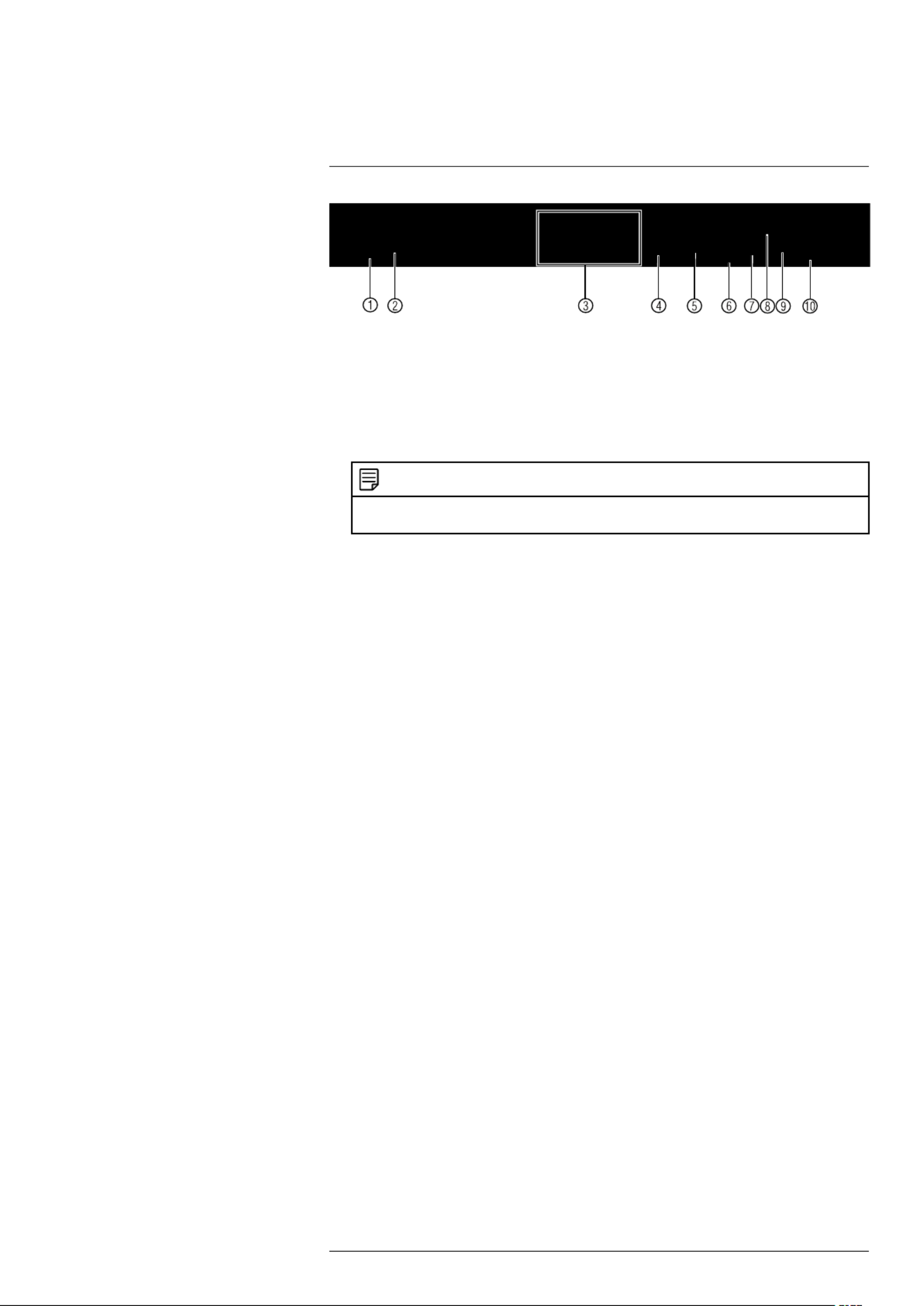
Rear Panel (DNR400 Series)
5
1. Power input: Connect the included AC power cable.
2. : Turns the NVR on or off.On / Off switch
3. PoE Ports: Connect IP cameras. Integrated PoE (Power Over Ethernet) ports provide
power to cameras and video connection to NVR.
4. : Connect a CAT 5 RJ45 Ethernet cable for local and remote connectivity.LAN
5. VGA: Connect a VGA monitor (not included) to view the system interface.
6. : RCA input and output for 2–way audio.MIC IN/OUT
NOTE
Audio-enabled IP cameras (not included) are required to use audio recording. You cannot record
audio from the input (e.g. microphone) connected to the MIC IN port.
7. : Connect to an HDMI monitor or TV (not included) to view the system interface.HDMI
8. : Service only; not supported.RS232
9. : Connect a USB mouse (included) or USB thumb drive (not included)USB port(s)
for data backup or firmware updates.
10. : Connect alarm/sensor devices (not included).Alarm block
#LX400022; r.16694/30364; en-US 7

Basic Setup (DNR400 Series)
6
6.1 Step 1: Connect the IP Cameras
Option 1: Direct Connection to NVR
• Connect cameras to the PoE Ports on the rear panel of the NVR using Cat5e or high-
er grade Ethernet cable. The cameras will appear on the NVR without any additional
configuration when the system starts up.
Connect IP cameras directly to PoE ports.
Option 2: Connect Cameras to Local Network
You can also connect your IP cameras to your local network for flexible installations. For
details, see 6.11 , page 11.Connecting Cameras to the Local Area Network (LAN)
6.2 Step 2: Connect the Mouse
• Connect a USB mouse (included) to one of the ports.USB
6.3 Step 3: Connect the Ethernet Cable
• Connect an Ethernet cable (included) to the port on the rear panel of the system.LAN
Connect the other end of the Ethernet cable to a router on your network.
6.4 Step 4: Connect the Monitor
• Connect the included HDMI cable from the port to the TV or monitorHDMI
(recommended).
OR
#LX400022; r.16694/30364; en-US 8

Basic Setup (DNR400 Series)
6
• Connect a VGA cable (not included) from the VGA port to the monitor.
1. VGA port.
2. HDMI port.
6.5 Step 5: Connect the Power Cable to Power the NVR
• Connect the included AC power cable to the NVR and connect the other end to a
power outlet or surge protector. Then turn the power switch to to power on the NVR.l
At startup, the system performs a basic system check and runs an initial loading se-
quence. After a few moments, the system loads a live display view.
6.6 Step 6: Upgrade Firmware to Latest Version (if Available)
If a firmware upgrade is available, you will be asked to install it once the system starts up.
It is required to upgrade your system firmware and client software or mobile apps to the
latest version to enable remote connection to the system.
If a firmware upgrade is available:
1. After startup, a notification will appear asking you to upgrade the firmware. Click OK
to upgrade.
2. Enter the system user name (default: ) and password (default: ) andadmin 000000
click . Wait for the firmware update to complete. The system will restart once theOK
firmware has been upgraded.
WARNING
DO NOT POWER OFF THE SYSTEM OR DISCONNECT THE POWER CABLE DURING FIRM-
WARE INSTALLATION
6.7 Step 7: Verify Camera Image
• Power on the cameras, and then verify the camera video quality before mounting the
cameras to a permanent location.
• Mount the cameras under a sheltered location. Always verify the outdoor rating of your
camera before installing it in a permanent location.
6.8 Step 8: Set the Time
• Set the system time and date for accurate video time stamps. Videos with inaccurate
times may not be valid as surveillance evidence.
• For details on setting the system time, see 10 , page 23.Setting The Time
#LX400022; r.16694/30364; en-US 9

Basic Setup (DNR400 Series)
6
6.9 Default System Password & Port Numbers
CAUTION
By default, the system user name is and the password is . It is essential that you createadmin 000000
your own password. For details, see 14 , page 37.Managing Passwords and User Accounts
The system requires a user name and password to log in to the system remotely using a
computer or mobile device. After logging on remotely the first time, you will be asked to
create a custom password for the system.
Local system and remote connectivity (LAN & Internet) user name and password:
• Username: admin
• Password: 000000
Default ports for DDNS remote access:
• Port (HTTP port)80
• Port (Client port)35000
6.9.1 FLIR Cloud™
This system features the exclusive FLIR Cloud™. This is a cloud service that allows you
to connect to your system over the Internet via a secure handshake with our servers. This
means you can easily connect to your system without requiring any network
configuration.
For details on setting up your system to connect to the Internet using FLIR
Cloud™:
• See 16 Connecting to Your System Over the Internet on PC or Mac, page 72.
OR
• See 18 Connecting to your System Using Smartphone or Tablet Apps, page 100.
Connectivity using FLIR’s free DDNS service is also available, but requires the ports
listed above to be port forwarded on your router.
6.10 Quick Access to System Information
To quickly open a window that displays vital system information:
• Right-click to open the Quick Menu and click . Enter the system user name (de-Info
fault: ) and password (default: ).admin 000000
OR
• Press the button on the front panel.ENTER
OR
• Press the button on the remote control.ENTER
NOTE
The QR code shown in the System Info screen can be scanned during mobile setup to enter the sys-
tem’s Device ID.
#LX400022; r.16694/30364; en-US 10

Basic Setup (DNR400 Series)
6
6.11 Connecting Cameras to the Local Area Network (LAN)
For flexibility, you may also connect IP cameras to the same Local Area Network (LAN)
as the NVR. This is accomplished by connecting the cameras to the same router as the
NVR.
For these installations, an external PoE switch (sold separately) or power adapter (sold
separately) must be used to provide power to each IP camera. You also must add the
cameras on the NVR before they will show a picture on the monitor or be recorded by
the NVR.
Follow the steps below to connect the cameras to the NVR over the LAN.
NOTE
• For a list of 3rd party IP cameras supported, please visit www.flirsecurity.com/pro.
• Camera and NVR images in this section are used for illustration only.
Step 1 of 2 — Option A: Connecting cameras to your local network using a PoE
switch:
1. Connect an Ethernet cable from the LAN port on an external PoE switch (sold sepa-
rately on www.flirsecurity.com/pro) to your router using a CAT5e or higher Ethernet
cable. Connect the power cable to the PoE swtich and to a power outlet or surge
protector.
NOTE
Terminology may vary depending on the model of PoE switch you have.
2. Connect the IP cameras to the PoE switch using the Ethernet extension cables. The
PoE switch will provide power and video transmission the same way as your NVR.
#LX400022; r.16694/30364; en-US 11

Basic Setup (DNR400 Series)
6
Step 1 of 2 — Option B: Connecting cameras to your local network using power
adapters:
1. Connect each camera to a compatible power adapter (visit www.flirsecurity.com/pro
for compatible power adapters for your cameras).
2. Connect the camera to your router using a CAT5e or higher Ethernet cable.
Step 2 of 2: Add the cameras to your NVR:
1. Right-click and select .Device Search
2. Log in using the admin account (default User Name: ; default Password:admin
000000).
3. Click . The system searches the network for compatible cameras.Device Search
4. Check the camera(s) you would like to add.
#LX400022; r.16694/30364; en-US 12

Basic Setup (DNR400 Series)
6
5. Click . The Status indicator turns green to show the camera is successfullyAdd
connected.
NOTE
If the Status indicator is red, click and update the info for your IP camera. Click to saveOK
changes.
6. Click to save changes.OK
NOTE
You can also add a camera to a specific channel by hovering the mouse over an empty channel in split-
screen view and clicking . Then double-click the camera you would like to add and right click to exit.
#LX400022; r.16694/30364; en-US 13

Mouse Control
7
The mouse is the primary control device for the system. To connect a USB mouse:
• Connect a USB mouse to the USB port on the front or rear panel.
1. :Left-button
• In live view, click to open the Navigation Bar. Right-click to close the navigation
bar.
• In live view, while in a split-screen display mode, double-click an individual chan-
nel to view it in full-screen. Double-click again to return to the split-screen display
mode.
• While navigating menus, click to open a menu option.
2. :Right-button
• During live view, right-click anywhere on the screen to open the Quick Menu.
• Within system menus, right-click to exit menus.
3. : In live view, use the scroll wheel to zoom in/out.Scroll wheel
#LX400022; r.16694/30364; en-US 14

Remote Control
8
1. Power: Press and hold to power off the system. Press to power on.
2. :Playback controls
•Pause/Play: In live view, press to enter playback mode. Press to play/pause
playback.
•Reverse: Press to reverse playback/pause playback.
•Fast: Press to increase playback speed.
•Next: Press to skip to next video.
•Previous: Press to skip to previous video.
•Slow: Press for slow playback.
3. : In menus, press to go back / exit menus. In playback, press to return to live view.Esc
4. Directional keys:
• : Press once to open the System Information screen; press twice to openEnter
the Navigation Bar. Press to confirm menu selections.
• Press to move the menu cursor.
• Press to change menu options.
5. : Press to switch between full-screen and split-screen layouts.Mult
6. Number keys:
• : In live view, press to open channels in full-screen.1~0
• In menus, press to input numbers or text input.
• : Press to change input types.Shift
7. : Configure remote control address. See below for details.Add
8. : Press to open manual record menu.Rec
9. : Press to perform special functions in some menus.Fn
8.1 Setting the Remote Control Address
If you have more than one system, you can set up your remote control to pair with a spe-
cific system.
#LX400022; r.16694/30364; en-US 15

Remote Control
8
To set the remote control address:
1. Right-click and click Main Menu. Enter the system user name (default: ) andadmin
password (default: ).000000
2. Click and then click .Setting>General>General
3. Under Device No., enter the address number you would like to assign to the remote
control.
4. Click .OK
5. Using the remote control, press . Then enter the address number and pressAdd
Enter.
NOTE
When entering the address number using the remote, make sure that you press three digits. A sin-
gle-digit number should be preceded by two zeros. A two-digit number should be preceded by one
zero. For example, if you entered as the , you have to press then on the8 Device No. Add 008
remote.
#LX400022; r.16694/30364; en-US 16
Using the System
9
Use the system’s graphical on-screen display to navigate menus and configure options
and settings.
NOTE
Up to four channels at a time may be viewed using the system’s high definition Main Stream. If more
than four channels need to be viewed, additional channels will be displayed using the lower resolution
Sub Stream. Although the live display picture will not be as sharp on these channels, all channels will
still be recorded in high definition by default.
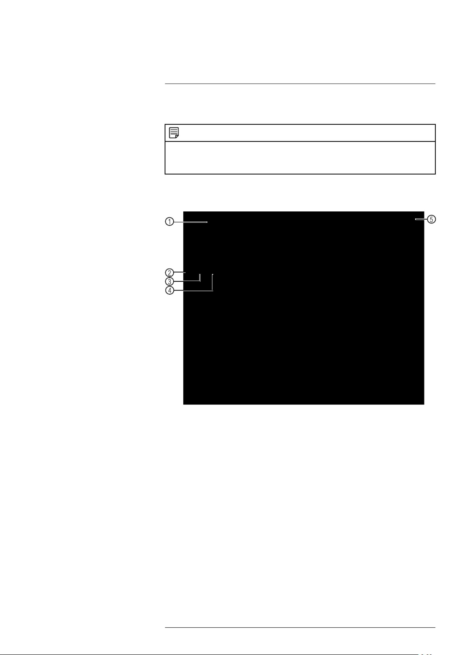
9.1 On-Screen Display
The system shows the following for all display views:
1. :Display area
• Double-click on a channel to view in full-screen; double-click again to return to split
screen.
• Right-click to open the Quick Menu.
• Left-click to open the Navigation Bar.
• Move the mouse to the top of a channel to view the Camera Toolbar.
• Click-and-drag cameras to rearrange the channel display. This does not affect the
channels each camera is connected or recording to.
2. Channel name
3. : Camera is continuously recording.C
4. : Motion has been detected.M
5. : Current system date and time. For details on setting the date and time,Date & time
see 10 , page 23.Setting The Time
#LX400022; r.16694/30364; en-US 17

Using the System
9
9.2 Using the Quick Menu
The Quick menu gives you access to the system’s key functions. To access the Quick
Menu, right-click the screen during live view.
The Quick Menu has the following options:
• : Select a camera in full-screen or select a multi-channel display.View
•Pan/Tilt/Zoom: Access controls for PTZ cameras (not included).
• : Access zoom/focus controls for auto-focus cameras (not included).AutoFocus
• : Configure image settings for cameras.Color Setting
• : Opens the system information window.Info
• : Click to start/stop sequence mode.Sequence
In sequence mode, the system will automatically cycle through connected cameras
every few seconds. A will appear to show that sequence mode is on.
Click the icon to pause sequence mode on the channel that is currently shown (icon
changes to ). Click again to resume sequence mode.
Right-click and select to return to normal viewing mode.Sequence
• : Search/playback recorded video. See 12 , page 26.Search Search (Playback)
• : Click to open the Record menu to select manual recordingManual Control Record
options. See 11.3 , page 24. ClickSetting up Scheduled or Manual Recording Alarm
Output to control alarm ouput devices (not included).
• : Open the Device Search menu to manage IP cameras over the localDevice Search
network.
• : Open the Main Menu. See 15 , page 41.Main Menu Using the Main Menu
9.3 Adjusting Camera Image Settings
Use the Camera menu to adjust image settings for your cameras.
To adjust image settings:
1. Right-click on the channel you would like to configure and select .Camera Setting
Enter the system password if prompted.
#LX400022; r.16694/30364; en-US 18
Using the System
9
2. Configure the following settings as needed:
NOTE
The settings listed below are only shown if they are supported on the selected camera. Some cam-
era models do not support all settings.
• : Select to flip the image horizontally.Mirror Enable
• : Select to flip the image vertically, or select for the defaultFlip Flip 180° No Flip
orientation.
• : Select to turn on the camera’s noise reduction feature. Noise3D Denoise Enable
reduction will ensure a cleaner image, especially at night, and may reduce the
amount of disk space required to store video.
• : Select or to enable back light compensation or to dis-BLC Mode High Low Off
able. Back light compensation adjusts the lighting levels in the picture so you can
see objects in the foreground if there is a strong light source behind them.
• : The Scene Mode allows you to adjust white balance levels for theScene Mode
camera. Select for the camera to automatically adjust the white bal-Schedule
ance. Select or to use preset white balance levels. SelectSunny Night Custom-
ized to manually set blue and red levels.
• : This setting sets the camera’s day/night mode. Select for theDayLight Colorful
camera to use color mode at all times. Select for the camera to auto-Schedule
matically determine whether to use color or black and white mode. Select Black&-
White for the camera to use black and white mode at all times.
NOTE
It is recommended to select Schedule mode, as using Colorful may impact the camera’s per-
formance at night.
• : Adjust the vibrancy of colors in the image.Saturation
• : Adjust the color hue of the image.Hue
• : Adjust the image brightness.Brightness
• : Adjust the image contrast.Contrast
3. Click to save changes.OK
NOTE
You must save changes to apply settings changes. It is recommended to adjust one setting at a
time so you can see the results of each change. Click to reset the camera to default imageDefault
settings.
9.4 Using the Navigation Bar
The Navigation Bar gives quick access to certain functions and menus.
#LX400022; r.16694/30364; en-US 19

Using the System
9
To open the Navigation bar:
• Left click on the screen to open the Navigation Bar. The Navigation Bar has the follow-
ing options:
1. Main Menu.
2. Collapse.
3. Select display layout.
4. : Click to start/stop sequence mode.Sequence
5. : Click to open PTZ controls.PTZ
6. : Click to open camera image settings.Camera
7. : Search and playback recorded video. See 17.4 , page 83.Search Playback
8. : View alarms in progress. See 15.2.4Alarm Status Event Info, page 48.
9. : Click to access status information about connected cameras.Channel Info
10. Device Search: Manage IP cameras over the network.
11. : Configure network settings for your system. See 15.3.1 , pageNetwork Network
51.
12. : Manage hard drives connected to the system. See 15.3.19HDD Manager For-
matting the Hard Drive, page 63.
13. : Click to access options for connected USB thumb drives (not in-USB Manager
cluded). You can backup video, logs, or system configurations and install firmware
upgrades.
14. : Check for firmware upgrades. The system must be connectedSystem Upgrade
to the Internet to check for or receive updates.
9.5 Using the Camera Toolbar
The Camera Toolbar is used to perform actions on a specific channel.
To access the Camera Toolbar:
• Move the mouse to the top of the channel display. The Camera Toolbar has the follow-
ing options:
1. Quick Playback.
2. Digital zoom.
3. Real-time backup.
4. Snapshot.
5. 2–way audio.
6. Device Search.
9.5.1 Using Quick Playback
Quick Playback is used to playback the last 5~60 minutes of video from the selected
channel. You can also access Quick Playback in split-screen mode, while still viewing
live video from the other channels.
#LX400022; r.16694/30364; en-US 20

Using the System
9
To use Quick Playback:
1. Move your mouse to the top of the channel display and click .
NOTE
By default, the system will begin playback from 5 minutes ago. You can increase this to up to 60 mi-
nutes using the setting in .Instant Playback Main Menu>Setting>General
2. Right-click to exit Quick Playback.
9.5.2 Using Digital Zoom in Live Display
1. Move your mouse to the top of the channel display and click to activate digital
zoom. A check mark will appear in the icon to indicate digital zoom is activated
.
NOTE
You may activate digital zoom in multiple channels at the same time.
2. Click and drag inside the channel to zoom in.
• Click and drag to pan the zoom area.
• Right-click to zoom out and select a new zoom area.
• Click to disable digital zoom. Note that the channel will remain at the same
zoom level until you right-click inside it.
9.5.3 Using Real-time Backup
Real-time backup allows you to save footage from the live display to a USB thumb drive
(not included) or external hard drive (not included).
To use Real-time Backup:
1. Insert the USB thumb drive or external hard drive into one of the USB ports on the
system.
2. Move your mouse to the top of the channel display and click to start Real-time
Backup.
3. Click again to end Real-time Backup. The file is saved to your USB device.
NOTE
If the system prompts you to log in, you will need to click again to start Real-time Backup after
logging in.
9.6 Using the Virtual Keyboard
The Virtual Keyboard is used to input text or numeric values in certain menus.
#LX400022; r.16694/30364; en-US 21

Using the System
9
1. Backspace.
2. Enter capital letters.
3. Confirm entry.
9.7 Adjusting Camera Zoom & Focus
Auto-focus cameras (not included) have a motorized lens. The motorized lens allows you
to control the zoom and focus settings using the menus on your system.
To adjust the camera’s zoom focus:
1. Double-click on the channel where the motorized lens camera is connected.
2. Right-click and then click . Log into the system using the admin accountAutoFocus
(default user name is and password is ).admin 000000
3. Adjust the zoom and focus using the following options:
• Use the sliders to adjust the or settings for the camera.Zoom Focus
NOTE
Hover the mouse over the sliders and use the mouse wheel to adjust by 1% at a time.
• Click the button to automatically focus the camera at the current zoomAutoFocus
level.
• Click to return the camera to the default zoom and focus levels.Default
• Click to refresh the settings shown on the system if someone has used theRefresh
manual lens controls on the camera.
4. Right-click to exit and save changes.
#LX400022; r.16694/30364; en-US 22

Setting The Time
10
CAUTION
It is highly recommended to set the date and time when first setting up your system.
Inaccurate time stamps may render your footage unusable for court evidence.
To set the date and time:
1. In the main viewing mode, right-click and click .Main Menu
2. Log in using the system user name (default: ) and password (default: ).admin 000000
3. Click and select . Click and select the tab.Setting General Date&Time
4. Under , enter the current time and select your time zone. Then, clickSystem Time
OK.
5. Check the check box to enable auto Daylight Savings Time updates.DST
NOTE
• You can adjust the and for Daylights Savings Time if the default settingsStart Time End Time
do not match your region.
• Under DST Type Day of Week, select to set the start and end time based on a day and week (e.
g. 2nd Sunday in March), or select to set the start and end time to a specific date.Date
6. (Optional) Check the check box to sync your system with an Internet time server.NTP
Click to instantly update the time.Manual Update
NOTE
• Your system must have a constant connection to the Internet to use NTP.
• (Advanced) You can enter a custom NTP server under and , and you can selectServer IP Port
how often the system will sync the time using .Interval
7. Click to save changes.Apply
#LX400022; r.16694/30364; en-US 23

Recording11
By default, the system is set to immediately record video from connected cameras con-
tinuously, 24 hours a day. You can customize the recording settings according to your
needs.
11.1 Video Recording Types
The system supports the following recording types.
• : Normal, continuous recording. ARecording—Continuous icon is shown when
recording is in progress.
• : The system records when motion is detected by the camera.Recording—Motion
An icon is shown when motion is detected.
11.2 Main Stream and Sub Stream
The system employs two video recording streams, a Main Stream and a Sub Stream.
Both Main Stream and Sub Stream recording are enabled by default.
The Main Stream records high quality video to your system’s hard drive.
The Sub Stream records lower resolution video for efficient streaming to devices over
the Internet. Sub Stream recording must be enabled to view video recordings on a com-
puter or mobile device.
You can configure the video quality parameters for the Main Stream or Sub Stream. For
details, see 15.1.6 Configuring Recording Quality, page 43.
11.3 Setting up Scheduled or Manual Recording
You can set the system to record based on a schedule or you can manually turn record-
ing on and off. By default, the system is set to record on an always on recording
schedule.
To configure the recording schedule, see 15.3.15 Configuring the Video Recording
Schedule, page 60.
To select between scheduled and manual recording:
1. Right-click and then select .Manual>Record
2. Under , select how the system will record the Main Stream for eachMain Stream
channel.
• : Main Stream Recording will follow the recording schedule.Schedule
• : The system will record the Main Stream continuously as long as this op-Manual
tion is checked.
• : The system will not record the Main Stream for this channel. This option isStop
not recommended.
#LX400022; r.16694/30364; en-US 24

Recording11
3. Under , select how the system will record the Sub Stream for eachSub Stream
channel.
• : Sub Stream Recording will follow the recording schedule.Schedule
• : The system will record the Sub Stream continuously as long as this op-Manual
tion is checked.
• : The system will not record the Sub Stream for this channel.Stop
4. Under , select to enable snapshot recording on each channel. Or,Snapshot Enable
select to disable snapshot recording.Disable
5. Click to save changes.OK
11.4 Configuring Hard Drive Overwrite
When the hard drive is full, the system will overwrite the oldest recordings by default.
This is recommended, as it makes sure that your system will continue to record without
any input from you. You can also set the system to stop recording once the hard drive is
full.
To configure hard drive overwrite:
1. Right-click and select . ClickMain Menu > Setting>General>General.
2. Under HDD Full Overwrite, select for the system to overwrite the oldest recordings
when the hard drive is full. Or, select for the system to stop recordingStop Record
when the hard drive is full.
3. Click to save changes.OK
#LX400022; r.16694/30364; en-US 25

Search (Playback)
12
Search mode is used to navigate and playback recorded video files on the system.
12.1 Playing Back Video from the Hard Drive
1. From live view, right-click and then click .Search
2. Log in using the system user name (default: ) and password (default: ).admin 000000
3. Configure the following:
3.1. Use the calendar on the right to select the day to playback.
3.2. Use the drop-down menus to select the channels you would like to playback.
NOTE
Click the display options ( ) to playback multiple channels simultaneously.
3.3. Click inside the video bar to select the playback time. The system will begin
playing back at the selected time.
#LX400022; r.16694/30364; en-US 26

Search (Playback)
12
4. Click to start the Smart Search playback. To stop the Smart Search playback,
click again.
#LX400022; r.16694/30364; en-US 29
Backup13
3. Click >Backup.
4. Configure your search options:
• Select the USB device you would like to format under Device Name.
•Type All: Select the recording type you would like to search for or select to search
all recording types.
• : Select the channel you would like to search or select to search allChannel All
channels.
• : SelectFile Format DAV to save files to save files to .dav format. You can play-
back .dav files using the FLIR video player software from www.flirsecurity.com/pro.
Or, select for .asf format. You can playback .asf files in VLC Media PlayerASF
(free download from www.videolan.org) on PC or Mac.
NOTE
VLC Media Player is a free software available from www.videolan.org. VLC Media Player is not
supported by FLIR.
• : Select the start and end time for your search.Start Time/End Time
5. Click . A list of files that match your search criteria appears.Add
6. Check files you would like to backup and then click . Wait for the backup toBackup
complete.
NOTE
HD video files saved on the system may take up a large amount of disk space. The size of video
files selected and the amount of free space on your USB device is shown at the top of the screen.
13.3 Using Video Clip Backup
Video clip backup allows you to select a duration of video during playback mode and
save it to a USB device (not included).
To use Video Clip Backup:
1. Insert a USB thumb drive (not included) or USB external hard drive (not included) into
one of the USB ports.
2. Start playing back video using the steps in 12.1 Playing Back Video from the Hard
Drive, page 26.
3. Click to mark the beginning of the video clip. Click again to mark the end
of the video clip.
4. Click to open the Backup menu.
#LX400022; r.16694/30364; en-US 31

Backup13
5. Configure the following:
5.1. Check the USB device where you would like to save the file.
5.2. Check the files you would like to backup.
5.3. Click . Then click . Wait for the backup to complete before re-Backup Start
moving the USB thumb drive.
13.4 Viewing Backup Files
To playback .dav backup video files, aFLIR Cloud™ Player is available for PC and Mac
at www.flirsecurity.com/pro.
13.4.1 Viewing Backup Files on PC
You can download fromVideo Player for PC www.flirsecurity.com/pro.
To view backup video files using the Player on PC:
1. Download and install the Video Player for PC from www.flirsecurity.com/pro.
2. Click to open a back up video file.
3. Use the Player controls to control playback or select other files for playback.
#LX400022; r.16694/30364; en-US 32
Backup13
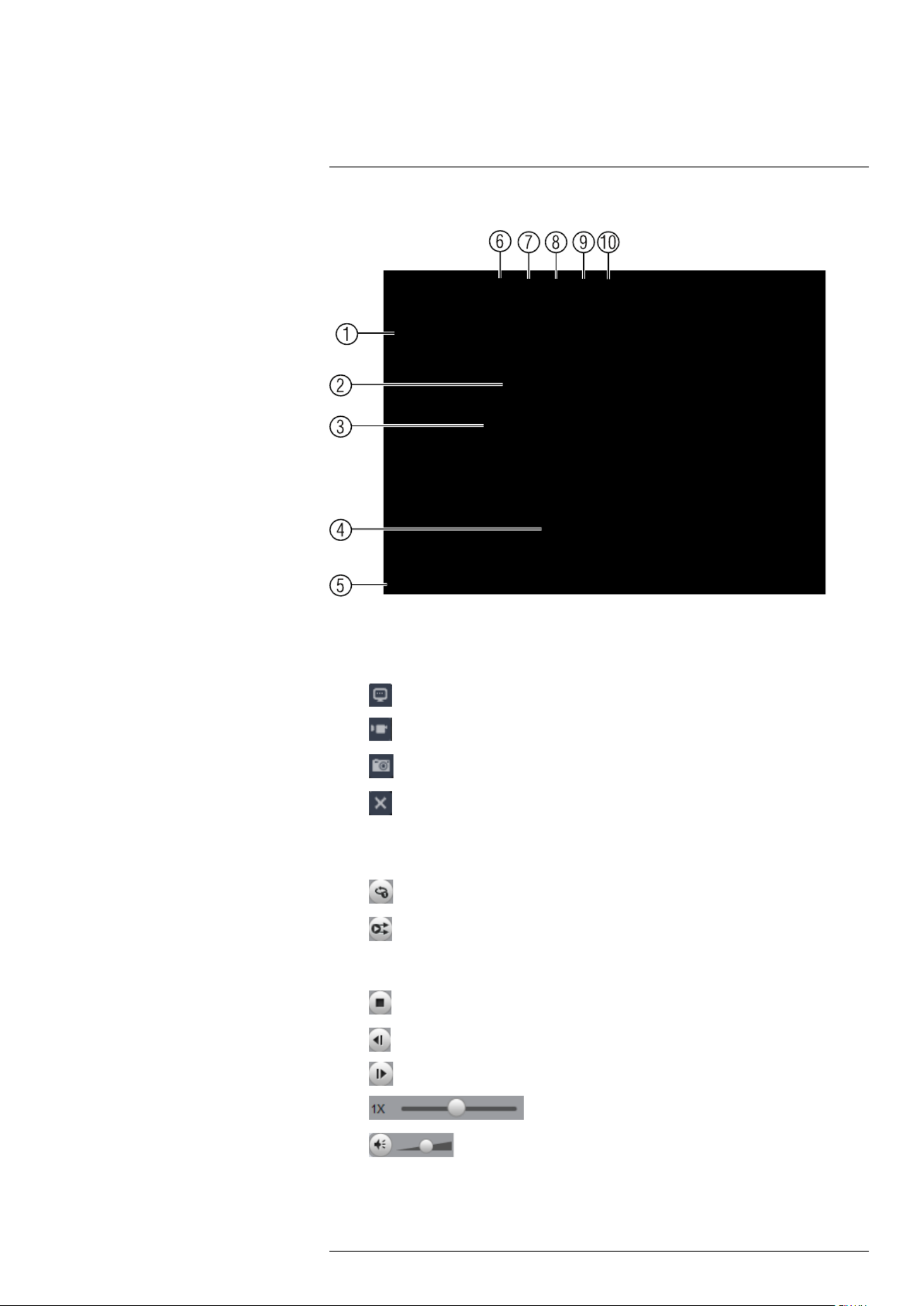
Video Player Controls
1. : Double-click to open a file.File List
2. : Select the split-screen mode. Double-click a video file to expand.Display Area
Click the controls inside the display area to do the following:
• : View information about the video file.
• : Start/stop a manual recording from the video file.
• : Take a snapshot from the video file.
• : Close the video file.
3. Hide/show file list.
4. :Playback controls
• : Playback files in sequence.
• : Synchronize playback times.
• : Play/pause playback.
• : Stop playback.
• : Previous frame.
• : Next frame.
• : Playback speed.
• : Volume control.
5. Zoom Timeline.
6. : Click to open back up video files.Add Files
#LX400022; r.16694/30364; en-US 33

Backup13
7. : Click to activate digital zoom mode. Click and drag in the video toDigital Zoom
zoom in. Right-click to unzoom.
8. : When digital zoom is activated, click to activate drag mode. Then click andDrag
drag in the video to view different areas of the image.
9. Full-screen: Click to open the player in full screen. Press to exit full screen.ESC
10. : Click to open the configuration menu for the player. From here you can con-Config
trol the default file formats and save locations for snapshots and video files saved
from the player.
13.4.2 Viewing Backup Files on Mac
A Video Player for Mac is available from www.flirsecurity.com/pro.
To view backup video files using the Player on Mac:
1. Download fromVideo Player for Mac www.flirsecurity.com/pro.
2. Double click the downloaded file in Safari to extract the Smart Player app file.
3. Drag the Smart Player Smartapp to your Desktop or Applications list. Double click
Player ( ) to open it.
#LX400022; r.16694/30364; en-US 34

Backup13
4. Click to open a back up video file in another location.
5. Use the Player controls to control playback or select other files for playback.
Video Player Controls
1. : Double-click to open a file.File List
2. : Select the split-screen mode. Double-click a video file to expand.Display Area
Click the controls inside the display area to do the following:
• : View information about the video file.
• : Take a snapshot from the video file.
• : Close the video file.
3. Hide/show file list.
#LX400022; r.16694/30364; en-US 35
Backup13
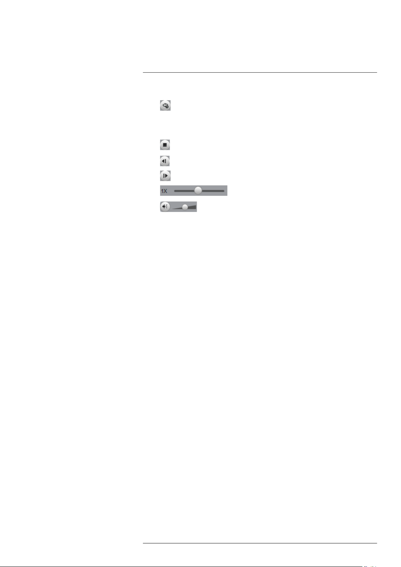
4. :Playback controls
• : When a video file ends, this button lets you select if you want the video player
to repeat the same file or play the next file.
• : Play/pause playback.
• : Stop playback.
• : Previous file.
• : Next file.
• : Playback speed.
• : Volume control.
5. Zoom Timeline.
6. : Click to open back up video files.Add Files
7. Full-screen: Click to open the player in full screen. Press to exit full screen.ESC
8. : Click to open the configuration menu for the player. From here you can con-Config
trol the default file formats and save locations for snapshots and control the aspect
ratio.
9. : Click to see version information for the Player software.About
#LX400022; r.16694/30364; en-US 36

Managing Passwords and User
Accounts
14
By default, the system user name is and the password is . Passwords areadmin 000000
enabled by default and are required to access the Main Menu or connect to the system
using a computer or mobile device. You will be prompted to create a custom password
after you connect for the first time.
NOTE
If you forget the password to the system, contact technical support to have it reset.
The system includes the following default accounts:
• : The admin account has full access to the system, may configure all systemadmin
settings, and can manage user accounts.
• : The default account is a limited user account that may only view live videodefault
from the cameras.
For security reasons, it is essential that you change the password on your system. By
default, the system password is enabled.
14.1 Changing Passwords
You can change the system password of the admin and user accounts from the Users
menu.
To modify an account password:
1. From Live View, right-click and then select .Main Menu
2. If prompted, enter the system user name (default: ) and password (default:admin
000000).
3. Click and select . Select .Setting Account
4. Click next to the user account you would like to modify.
5. Check Modify Password.
6. Under Old Password, enter the account’s previous password.
7. Under New Password, enter a new 6 character password for the account. Repeat
the new password under Confirm Password.
8. Click to save changes.OK
14.2 Adding Users
You can allow multiple users to log in to the system. When adding different users, you
can assign what menus they have access to. For example, you may want your friend to
monitor your system while you are away, while not giving full access to your system.
To add a user account:
1. From Live View, right-click and then select .Main Menu
#LX400022; r.16694/30364; en-US 37

Managing Passwords and User Accounts14
2. If prompted, enter the system user name (default: ) and password (default:admin
000000).
3. Click and select . Select .Setting Account
4. Click Add User.
5. Configure the following:
• : Enter a name for the user account.Username
•Password: Enter a 6 character password for the user account. Enter the pass-
word again under Confirm Password.
• : Enter a description of the user account.Memo (optional)
• : Select the group you would like to assign to this user account. A user ac-Group
count cannot be given permissions its group does not have.
• : Check to enable this user account to be used to login from more thanMultiuser
one device at the same time.
• : Check the permissions you would like the user account to have. UnderAuthority
the tab, select the menus the user account may access. Under theSystem Play-
back tab, select which channels the user account may access recorded video
from. Under the tab, select the channels the user account may view liveCovert
video from.
6. Click to save changes.OK
Now, you can log in to the system locally, or remotely using the user name and password
you created. When logging into the system with a user account, the user will only have
access to the menus you assigned.
14.3 Modifying Users
1. In the Account menu, click next to the user account you would like to modify.
2. Update the user’s account details as needed, and then click to save changes.OK
14.4 Deleting Users
1. In the Account menu, click next to the user account you would like to delete.
2. Click to confirm.OK
NOTE
The admin and default user accounts cannot be deleted from the system.
14.5 Account Groups
Account groups can be used to easily manage permissions for multiple user accounts.
User accounts can be given all the permissions of a group, but cannot be given permis-
sions that the group does not have.
#LX400022; r.16694/30364; en-US 38

Managing Passwords and User Accounts14
The system includes the following groups by default:
• : Accounts in the admin group are system administrators. They have full accessadmin
to the system, may configure all system settings, and can manage user accounts.
• : Accounts in the user group are normal users. They have limited access to sys-user
tem menus.
14.6 Adding Groups
1. From Live View, right-click and then select .Main Menu
2. If prompted, enter the system user name (default: ) and password (default:admin
000000).
3. Click and select .Setting
4. Click and select the tab.Account Group
5. Click .Add Group
6. Configure the following:
• Under , enter a name for the group.Group Name
• Under Memo, enter an optional comment for this group.
• Under Authority, check the permissions that the group will have. User accounts
assigned to this group can not be given any permissions the group does not have.
7. Click to save changes.OK
14.7 Modifying Groups
1. In the Group tab, click next to the group you would like to modify.
2. Update the group’s details as needed, and then click to save changes.OK
14.8 Deleting Groups
1. In the Account menu, click next to the user account you would like to delete.
#LX400022; r.16694/30364; en-US 39

Managing Passwords and User Accounts14
2. Click to confirm.OK
NOTE
The admin and user groups cannot be deleted from the system.
#LX400022; r.16694/30364; en-US 40

Using the Main Menu15
To open the Main Menu:
• : Right-click and click .Using the mouse Main Menu
NOTE
The system password is required to access the Main Menu. By default the user name is andadmin
the password is .000000
1. : Open Search/Playback mode. For details, see 12 ,SEARCH Search (Playback)
page 26.
2. BACKUP: Export files to USB device. For details, see 13 , page 30.Backup
3. : Open the menu to manage IP cameras connected to the network (seeCAMERA
6.11 for details), set recordingConnecting Cameras to the Local Area Network (LAN)
parameters, and assign custom titles for your cameras.
4. : View system information.INFO
5. : Configure general system, schedule, network, recording, display, and mo-SETTING
tion settings. Restore system to factory defaults.
6. : Logout, restart, or shutdown the system.SHUTDOWN
15.1 Camera
Open the Remote Device menu to manage IP cameras, set recording parameters, and
assign custom titles for your cameras.
15.1.1 Remote Device
The Remote Device menus allow you to add cameras over the local area network (LAN),
configure camera image settings, view camera status, and upgrade camera firmware.
• See 6.11 , page 11 for instruc-Connecting Cameras to the Local Area Network (LAN)
tions on connecting cameras to the NVR over the network.
• See 9.3 , page 18 for details on setting up cameraAdjusting Camera Image Settings
image settings.
15.1.2 Viewing Camera Status
The Camera Status menu allows you to view the connection and alarm status for all con-
nected cameras.
#LX400022; r.16694/30364; en-US 41
Using the Main Menu15
4. Right-click and select . Click and selectMain Menu Remote
Device>Upgrade.
5. Click . Select the firmware file on the USB drive and click .Select OK
6. Check the cameras you would like to apply the upgrade to in the list and then click
Start Upgrade.
CAUTION
Wait for the firmware upgrade to complete before turning off or unplugging the cameras or NVR.
The cameras will restart during the firmware update process.
15.1.5 Recording
The Recording menu allows you to set recording parameters for your cameras, such as
the resolution and frame rate.
15.1.6 Configuring Recording Quality
The system employs two video recording streams, a Main Stream and a Sub Stream.
The Main Stream records high quality video to your system’s hard drive. The Sub Stream
records lower resolution video for efficient streaming to devices over the Internet. You
can customize the video quality settings for these streams according to your needs.
To configure recording quality:
1. From the Main Menu, click and select .Recording>Recording
2. Under , select the camera you would like to configure.Channel
#LX400022; r.16694/30364; en-US 43

Using the Main Menu15
3. Configure the following settings. Settings for the Main Stream are in the left column.
Settings for the Sub Stream are in the right column.
• : Select the resolution that you want to use to record the selectedResolution
channel. Higher resolutions create a more detailed image, but take up more hard
drive space to record and require more bandwidth to stream to connected com-
puters or mobile devices.
NOTE
Available resolutions for the Main Stream and Sub Stream depend on the model of camera that
is connected to the system.
• : Select the video compression type that will be used. It is recom-Compression
mended to select , as it will have the best performance and use the leastH.264
amount of disk space.
• : Select the frame rate in Frames Per Second (FPS) that eachFrame Rate (FPS)
stream will record at. A higher frame rate provides a smoother picture, but requires
more storage and bandwidth.
•Bit Rate Type CBR VBR: Select (Constant Bit Rate) or (Variable Bit Rate) to de-
termine the bit rate type. If you select VBR, you can set the video quality setting
between 1 and 6. If you select VBR, select the from (lowest) toQuality 1 6
(highest).
• : Select the bit rate for each recording stream. A higher bit rate re-Bit Rate (Kbps)
sults in a better image, but increases the amount of hard drive space or bandwidth
required.
4. (Optional) Click the button to copy recording settings to other channels.Copy
5. Click to save changes.OK
15.1.7 Configuring Audio Recording
The system supports audio recording.
NOTE
Audio-enabled cameras (not included) are required to use audio recording. The MIC IN port is reserved
for two-way audio.
#LX400022; r.16694/30364; en-US 44

Using the Main Menu15
To configure audio recording:
1. From the Main Menu, click and select .Recording>Recording
2. Select the audio-enabled camera under .Channel
3. Check the left checkbox to enable audio recording. Check the middleAudio/Video
checkbox to enable audio streaming to remote devices (such as a smartphone).
Check the right checkbox to enable video streaming to remote devices.
4. Click to save changes.OK
15.1.8 Configuring Snapshot Recording Settings
The system can be set to record snapshot images when a camera detects motion. These
snapshots can be viewed through the Search menu or can be attached to email alerts
and push notifications. The Snapshot tab in the Recording menu controls the quality and
recording parameters for each camera.
NOTE
In order to enable Snapshot recording, the following menu options must be configured:
• The Snapshot schedule must be enabled for times that you would like to save snapshots. See
15.3.17 , page 61.Configuring the Snapshot Schedule
• Snapshot recording must be enabled for motion detection in the Event menu. See 15.3.8 Configur-
ing Motion Detection, page 55.
To configure snapshot recording settings:
1. From the Main Menu, click and select .Recording>Snapshot
2. Under Snap Number, select the number of snapshots the system will take when the
snapshot button is pressed.
#LX400022; r.16694/30364; en-US 45

Using the Main Menu15
3. Configure the following settings for snapshots saved automatically from motion de-
tection or the snapshot schedule:
• : Select the channel you would like to configure.Channel
• : Select for the system to take snapshots according to the snapshotMode Timing
schedule (see 15.3.17 , page 61) SelectConfiguring the Snapshot Schedule Trig-
ger for the system to take snapshots only when triggered by motion detection
(snapshot must be enabled in the Motion Detect menu; see 15.3.8 Configuring
Motion Detection, page 55).
• : The image size is the same as the Main Stream resolution of theImage Size
camera.
• : Select the snapshot image quality between (lowest) andImage Quality 1 6
(highest).
• : Select the number of snapshots (up to 6) the system willSnapshot Frequency
take each time.
4. Click to save changes.OK
15.1.9 Creating Custom Channel Names
You can assign custom names to your cameras. For example, you can name your cam-
eras based on their location (e.g. hallway or front door).
To create custom channel names:
1. From the Main Menu, click and select .Channel Name
2. Enter a custom name for each channel.
3. Click to save changes.OK
#LX400022; r.16694/30364; en-US 46

Using the Main Menu15
15.2 Info
Info contains menus that show you system information.
15.2.1 HDD Info
The HDD Info sub-menu shows information related to the hard drives installed in the sys-
tem, including capacity, status, and type.
To access the HDD Info menu:
• From the Main Menu, click and then click .Info>HDD Info
15.2.2 Record Info
The Record Info menu shows the start and end times of recordings saved on the hard
drive.
#LX400022; r.16694/30364; en-US 47

Using the Main Menu15
To access the Record Info menu:
• From the Main Menu, click and then select Info>Record Info.
15.2.3 Version
The Version sub-menu allows you to view information about the current firmware installed
on the system.
To access the Version menu:
• From the Main Menu, click and then click Info>Version.
15.2.4 Event Info
The Event Info menu shows you a display of system alarms. Activated alarms are high-
lighted in white. Additional info such as channels that are currently detecting motion is
shown.
The following alarms are shown in the Alarm Status menu:
• : No hard drive is detected.No HDD
• : Hard drive error detected.Disk Error
• : Hard drive is full.Disk Full
• : More than one device on the network is using the same IP address.IP Conflict
• : System is not connected to the network.Net Offline
•MAC Conflict: More than one device on the network is using the same MAC address.
• : Sensor/alarm device (not included) has been triggered.External Alarm
• : Shows disconnected channels.Video Loss
• : Camera masking alarm has been triggered (e.g. someone hasCamera Masking
covered the camera lens).
• : Shows channels with active motion alarms.Motion Detect
• : Alarm/sensor device (not included) connected to camera has beenIPC Ext Alarm
triggered.
• : IP camera is offline.IPC Offline Alarm
#LX400022; r.16694/30364; en-US 48

Using the Main Menu15
To access the Event Info menu:
• From the Main Menu, click and then select .Event
15.2.5 Online Users
The Online Users menu shows a list of users connected to the system using computers
or mobile devices.
To access Online Users:
• From the Main Menu, click and then select .Network
15.2.6 Load
The Load menu shows you the network traffic your system is sending and receiving.
To access Load:
• From the Main Menu, click and then select .Network>Load
15.2.7 Test
#LX400022; r.16694/30364; en-US 49

Using the Main Menu15
The Test menu allows you to test if your system can connect to other devices over the
LAN or Internet. You can enter the IP address of a device and click Test to determine if
your system can connect to it.
To access Test:
• From the Main Menu, click and then select Network>Test.
15.2.8 BPS
The BPS sub-menu shows the bitrates of connected cameras. the bitrate is the amount
of data the camera is sending to the system.
To access BPS:
• From the Main Menu, click and then select .BPS
15.2.9 Log
The Log sub-menu allows you to search for system logs.
To search for system logs:
1. From the Main Menu, click and then select .Log
2. Under Type, select the log type to search for.
3. Under and , select the start and end time for your search.Start Time End Time
4. Click .Search
5. (Optional) Click to export logs to a USB thumb drive connected to theBackup
system.
#LX400022; r.16694/30364; en-US 50

Using the Main Menu15
3. Configure the following:
• : Enter the SMTP server address.SMTP Server
•Port: Enter the port used by the SMTP server.
• : Check if your server supports anonymous log ins. Otherwise, leaveAnonymous
this unchecked.
• : Enter the SMTP user name.User Name
•Password: Enter the SMTP password.
• : Enter the email address that will receive alerts.Receiver
• : Enter the sender’s email address.Sender
• : Enter the subject line for the email alert.Subject
• : Check to include a jpg image attachment of the camera.Attachment
NOTE
You must enable the Snapshot option for motion detection on each camera you would to receive
attachments. For details, see 15.3.8 , page 55.Configuring Motion Detection
•Encrypt Type SSL TLS None: Select or if your server uses encryption. Select if
your server does not use encryption.
• : Enter the interval between alert emails.Event Interval
• : Check to enable health check emails. Health check emails will beHealth Enable
sent periodically to ensure that the system is functioning normally.
• : Enter the interval in minutes for health check emails.Interval
4. Click Test to send a test email.
5. Click to save settings.OK
15.3.6 Configuring Switch Settings (Advanced)
You can configure the networking settings for the internal PoE switch.
CAUTION
It is recommended to leave this menu on the default settings. Changing the information in this menu
may disrupt the connection to the cameras.
To configure switch settings:
1. From live view, right-click and select .Main Menu
2. Click >Network>Switch Settings.
3. Configure the , , andIP Address Subnet Mask Gateway for the internal PoE switch.
4. Click . Click to save changes. The system will restart.OK Save
15.3.7 Event
The Event menu allows you to configure settings for motion detection, video loss, and
system warnings.
#LX400022; r.16694/30364; en-US 54

Using the Main Menu15
15.3.8 Configuring Motion Detection
Motion Detection events allow the system to mark footage that has motion. This allows
you to quickly locate relevant footage through Search. You can also configure system re-
sponses to motion detection events, such as activating the system buzzer or sending an
email alert.
To configure Motion Detection events:
1. From the Main Menu, click and then click .Event>Motion>Motion Detect
2. Under , select the channel you would like to configure.Channel
3. Check to enable motion detection on the selected channel.Enable
4. Click next to Region to configure which areas of the image will be enabled forSetup
motion detection. A grid will appear over the camera’s live view.
Motion Grid
• Areas enabled for motion detection are shown in color and areas that are disabled
are transparent.
• Hover the mouse at the top of the screen to select which motion area you would
like to configure. You can set up to 4 motion detection areas and customize the
sensitivity and threshold for motion detection separately for each area between 0
(lowest) and 100 (highest).
• The determines how sensitive the camera is to motion. For example, ifSensitivity
the sensitivity is high, small amounts of motion are more likely to trigger an event.
It is recommended to select a Sensitivity between 30~70.
• The determines how much motion is required to trigger an event. If theThreshold
amount of motion exceeds the threshold, an event occurs. It is recommended to
select a Threshold between 10~50.
• Right-click when finished.
NOTE
It is recommended to have a second person walk in front of the camera to test different Sensitivity
and Threshold settings to determine the best setting for your camera’s location.
#LX400022; r.16694/30364; en-US 55
Using the Main Menu15
5. Under Anti-dither, enter the anti-dither time. After a motion event occurs and motion
stops, if motion is detected within the anti-dither time, the system continues the mo-
tion event and includes the new motion within the first event, rather than creating a
new motion event.
6. Under Post_REC, enter the time the system will record after a motion event occurs.
7. To configure a schedule when motion detection will be enabled on this channel, click
Setup next to Period. Configure times when motion detection will be enabled. For ex-
ample, you may want to disable motion detection during business hours and enable it
outside of business hours. Click when finished.OK
NOTE
This setting can override scheduled motion recording. This means that motion recording will only
take place at times that are enabled both in the Schedule menu and here.
8. Configure the following system actions when motion is detected:
• : Check the box to activate alarm output devices (not included) that willAlarm Out
trigger when the selected channel detects motion. Select the alarm output devices
that will be activated when motion is detected.
• : Enter the number of seconds an alarm output device will activate after mo-Latch
tion is detected.
• : Check to enable an on-screen pop-up when one of your cam-Show Message
eras detects motion. On-screen pop-up shows the channels an event occurred on
and the type of event.
• : Check to enable the system to upload alerts to FLIR Cloud™Alarm Upload
Client.
• : Check to enable email alerts. You must configure email alerts beforeSend Email
you will be able to receive them (see 15.3.5 , page 53).Configuring Email Alerts
• : Select the channels that will record when motion is detected on the se-Channels
lected channel.
• : Check to enable PTZ actions when motion is detected (PTZPTZ Activation
camera required; not included). Click to select which PTZ actions will beSetup
taken by each camera.
• : Check to enable the system buzzer.Buzzer
• : Check to enable a custom sequence mode when motion is detectedSequence
on the selected channel. Then click the channels you would like to display in the
custom sequence mode.
• : Check to save a snapshot when the camera detects motion.Snapshot
9. Click to save changes.OK
15.3.9 Configuring Video Loss Settings
Video Loss occurs if the system loses connection to one of the cameras.
To configure Video Loss settings:
1. From the Main Menu, click and then click .Event>Motion>Video Loss
#LX400022; r.16694/30364; en-US 56

Using the Main Menu15
2. Under , select the channel you would like to configure.Channel
3. Check to enable video loss events for the selected channel.Enable
4. Configure the following to customize settings for video loss events:
•Period Setup: Click to configure a schedule for video loss events. It is recom-
mended to leave this on the default setting, so you can be alerted at any time one
of your cameras loses video.
• : Select the alarm output devices (not included) that will trigger whenAlarm Out
video loss occurs.
• : Enter the number of seconds an alarm output device will activate after vid-Latch
eo loss occurs.
• : Check to show a popup message on the monitor if one of yourShow Message
cameras loses video.
• : Check to enable the system to upload alerts to FLIR Cloud™Alarm Upload
Client.
• : Check to enable email alerts. You must configure email alerts beforeSend Email
you will be able to receive them (see 15.3.5 , page 53).Configuring Email Alerts
• : Click the checkbox to enable video recording when video loss occurs.Channels
You can then select the channels the system will record when video loss occurs
on the currently selected channel.
• : Check to enable PTZ actions when video loss occurs (PTZ cam-PTZ Activation
era required; not included). Click to select which PTZ actions will be takenSetup
by each camera.
•Post_REC: Enter the number of seconds the system will record after video loss
occurs.
• : Click the box to enable snapshot recording when video loss occurs.Snapshot
You can then select which channels will save snapshots when video loss occurs
on the currently selected channel.
• : Check to enable a custom sequence mode when video loss occursSequence
on the selected channel. Then click the channels you would like to display in the
custom sequence mode.
• : Check to enable the system buzzer when video loss occurs on the cur-Buzzer
rently selected channel.
5. Click to save changes.OK
15.3.10 Configuring Alarm Input Devices
You can connect alarm input devices such as motion sensors (not included) or glass
break detectors (not included) to the system. The system can be set to trigger recording
or take other actions when these devices are activated.
To configure alarm input devices (not included):
1. From the Main Menu, click and then click .Event>Alarm
#LX400022; r.16694/30364; en-US 57

Using the Main Menu15
2. Configure the following to activate an alarm input device:
• : Select the alarm input port the device is connected to.Alarm In
• : Check to enable the alarm input device connected to the selected port.Enable
•Type Normal Open Normal Close: Select or depending on the type of alarm in-
put device you have.
3. Configure the following system responses and parameters for the alarm input device:
•Period Setup: Click to configure the times of the week when the selected device
will be activated. By default, the device will be activated 24/7.
• : Enter the anti-dither time. After the device triggers, if it triggers againAnti-dither
within the anti-dither time, the system continues the event and includes the second
activation within the first event, rather than creating a new event.
• : Check the box to activate alarm output devices (not included) and se-Alarm Out
lect the alarm output devices (not included) will be activated when the selected de-
vice is triggered.
• : Enter the number of seconds an alarm output device will activate after theLatch
selected device is triggered.
• : Check to enable an on-screen pop-up when the selected deviceShow Message
is triggered.
• : Check to enable the system to upload alerts to FLIR Cloud™Alarm Upload
Client.
• : Check to enable email alerts. You must configure email alerts beforeSend Email
you will be able to receive them (see 15.3.5 , page 53).Configuring Email Alerts
• : Select the channels that will record when the selected device isChannels
triggered.
• : Check to enable PTZ actions when the selected device is trig-PTZ Activation
gered (PTZ camera required; not included). Click to select which PTZ ac-Setup
tions will be taken by each camera.
• : Check to enable a custom sequence mode when the alarm deviceSequence
triggers. Then click the channels you would like to display in the custom sequence
mode.
• : Check to enable the system buzzer.Buzzer
• : Check to save a snapshot.Snapshot
4. Click to save changes.OK
15.3.11 Controlling Alarm Output Devices
You can connect alarm output devices (not included), such as sirens or strobe lights, to
the system. The Alarm Output menu allows you to enable or disable alarm output devices
and manually an activated device.
To access the Alarm Output menu:
1. From the Main Menu, click and then click .Event>Alarm Output
#LX400022; r.16694/30364; en-US 58

Using the Main Menu15
To control alarm output devices:
• To enable alarm output devices, select or for each device youSchedule Manual
would like to enable. Select to disable the alarm output device. Click to saveStop OK
changes.
• To manually disable activated alarm devices, click under Alarm Release.OK
15.3.12 Configuring Hard Drive Warnings
Hard drive warnings will notify you if an issue is detected with the hard drive.
To configure hard drive warnings:
1. From the Main Menu, click and then click Event>Warning>HDD.
2. Under Event Type, select the hard drive event you would like to configure.
• : No hard drive detected.No Disk
• : A hard drive error has been detected.Disk Error
• : The hard drive is full or almost full. You can enter the percentage of diskDisk Full
space remaining that will trigger a warning under (e.g. when less thanLess Than
10% of the hard drive is empty, trigger a warning). Disk Full warnings will not occur
if overwrite is enabled.
• : Configure warnings for all hard drive events.All
3. Configure the responses the system will take when the selected event occurs:
• : Activate selected alarm out devices. Use to select the numberAlarm Out Latch
of seconds the alarm out device will be activated.
• : Show a popup message on the monitor.Show Message
• : Check to enable the system to upload alerts to FLIR Cloud™Alarm Upload
Client.
• : Check to enable email alerts. You must configure email alerts beforeSend Email
you will be able to receive them (see 15.3.5 , page 53).Configuring Email Alerts
• : Check to activate the system buzzer.Buzzer
4. Click to save changes.OK
15.3.13 Configuring Network Warnings
Network warnings will notify you if your system loses connection to the Internet or local
network or if there is an issue on your network.
#LX400022; r.16694/30364; en-US 59

Using the Main Menu15
• : Normal recording hard drive.Read-write HDD
• : The system can playback data from this hard drive, but it will not re-Read-only HDD
cord to it.
• : The hard drive will be used for mirror recording only. You must set upMirror HDD
mirroring recording before this feature will work.
To set the hard drive type:
1. From the Main Menu, click and then click Storage>HDD Manager.
2. Click the hard drive you would like to configure.
3. Under Type Read-write HDD, select , Read-only HDD, or Mirror HDD.
4. Click to save changes. The system will restart to complete this operation.OK
15.3.21 Setting up Hard Drive Mirroring (Advanced)
A mirror hard drive can be used to automatically backup video footage recorded to the
recording (read-write) hard drive. When a mirroring hard drive is installed, the system
can be set to record cameras in parallel to both the recording hard drive and the mirror
hard drive. This way, the footage is automatically backed up if the recording hard drive
fails.
How hard drive mirroring works:
1. Security system.
2. Primary hard drive.
3. Mirror hard drive.
NOTE
• The mirror hard drive must be as large or larger than primary hard drive to backup all recordings.
• HDD mirroring begins from when mirror hard drive is installed and configured.
• Two hard drives must be installed in the system to use HDD mirroring. For details on installing hard
drives, see 22 , page 153.DNR400 Series Hard Drive Installation
To set up hard drive mirroring:
1. From the Main Menu, click and then click Storage>HDD Manager.
#LX400022; r.16694/30364; en-US 64
Using the Main Menu15
2. Click the Type Mirror HDDdrop-down under the second hard drive and select .
CAUTION
Setting a hard drive for mirroring erases on the hard drive.all data This step cannot be undone.
3. Click to apply changes. ClickOK Yes to confirm. The system will format the hard
drive and restart.
4. When the system restarts, click and then click
Storage>Schedule>Record.
5. Under , select the channel you would like to enable for mirror recording, thenChannel
check . Repeat the process for any additional channels.Mirroring
6. Click to save changes.OK
15.3.22 Configuring Hard Drive Groups (Advanced)
Hard drive groups allow you to balance recordings across multiple hard drives. For ex-
ample, you can record channels 1~4 to one hard drive and 4~8 to a second hard drive.
This can reduce the amount of wear on the hard drives and may extend the life of the
hard drives.
NOTE
• Two hard drives must be installed in the system to use hard drive groups, and both hard drives must
be formatted as Read-write hard drives. For details on installing hard drives, see 22 DNR400 Series
Hard Drive Installation, page 153.
To configure hard drive groups:
1. From the Main Menu, click and then click Storage>HDD Advance>HDD
Setting.
#LX400022; r.16694/30364; en-US 65
Termékspecifikációk
| Márka: | Flir |
| Kategória: | Térfigyelő kamera |
| Modell: | DNR408R12 |
Szüksége van segítségre?
Ha segítségre van szüksége Flir DNR408R12, tegyen fel kérdést alább, és más felhasználók válaszolnak Önnek
Útmutatók Térfigyelő kamera Flir

13 Január 2025
2 Október 2024
28 Szeptember 2024
14 Szeptember 2024
9 Szeptember 2024
9 Szeptember 2024
2 Szeptember 2024
2 Szeptember 2024
26 Augusztus 2024
25 Augusztus 2024
Útmutatók Térfigyelő kamera
- Térfigyelő kamera Samsung
- Térfigyelő kamera Sony
- Térfigyelő kamera August
- Térfigyelő kamera Nedis
- Térfigyelő kamera Grundig
- Térfigyelő kamera Philips
- Térfigyelő kamera Pioneer
- Térfigyelő kamera Reolink
- Térfigyelő kamera Garmin
- Térfigyelő kamera Bosch
- Térfigyelő kamera Panasonic
- Térfigyelő kamera Canon
- Térfigyelő kamera JVC
- Térfigyelő kamera Evolveo
- Térfigyelő kamera Toshiba
- Térfigyelő kamera Ubiquiti Networks
- Térfigyelő kamera TP-Link
- Térfigyelő kamera Emos
- Térfigyelő kamera Motorola
- Térfigyelő kamera LogiLink
- Térfigyelő kamera Digitus
- Térfigyelő kamera Zebra
- Térfigyelő kamera Xiaomi
- Térfigyelő kamera TRENDnet
- Térfigyelő kamera EZVIZ
- Térfigyelő kamera Boss
- Térfigyelő kamera Crestron
- Térfigyelő kamera ORNO
- Térfigyelő kamera Strong
- Térfigyelő kamera Gigaset
- Térfigyelő kamera MEE Audio
- Térfigyelő kamera Conceptronic
- Térfigyelő kamera Thomson
- Térfigyelő kamera Technaxx
- Térfigyelő kamera Speco Technologies
- Térfigyelő kamera Ricoh
- Térfigyelő kamera Hikvision
- Térfigyelő kamera Netgear
- Térfigyelő kamera Asus
- Térfigyelő kamera Vtech
- Térfigyelő kamera Rollei
- Térfigyelő kamera Hama
- Térfigyelő kamera Mitsubishi
- Térfigyelő kamera Synology
- Térfigyelő kamera Avidsen
- Térfigyelő kamera Raymarine
- Térfigyelő kamera DSC
- Térfigyelő kamera Kodak
- Térfigyelő kamera Ring
- Térfigyelő kamera V-TAC
- Térfigyelő kamera ZyXEL
- Térfigyelő kamera Logitech
- Térfigyelő kamera Dahua Technology
- Térfigyelő kamera Withings
- Térfigyelő kamera Denver
- Térfigyelő kamera First Alert
- Térfigyelő kamera Minox
- Térfigyelő kamera Trevi
- Térfigyelő kamera DiO
- Térfigyelő kamera Planet
- Térfigyelő kamera Burg Wächter
- Térfigyelő kamera Ernitec
- Térfigyelő kamera Tenda
- Térfigyelő kamera Qian
- Térfigyelő kamera Aluratek
- Térfigyelő kamera Extech
- Térfigyelő kamera Gembird
- Térfigyelő kamera Cisco
- Térfigyelő kamera Niceboy
- Térfigyelő kamera SPC
- Térfigyelő kamera Bea-fon
- Térfigyelő kamera Powerfix
- Térfigyelő kamera Edimax
- Térfigyelő kamera Eufy
- Térfigyelő kamera APC
- Térfigyelő kamera Overmax
- Térfigyelő kamera Lorex
- Térfigyelő kamera Foscam
- Térfigyelő kamera Manhattan
- Térfigyelő kamera Kogan
- Térfigyelő kamera Alecto
- Térfigyelő kamera Honeywell
- Térfigyelő kamera EnGenius
- Térfigyelő kamera Imou
- Térfigyelő kamera Marshall
- Térfigyelő kamera Acme
- Térfigyelő kamera Furrion
- Térfigyelő kamera Velleman
- Térfigyelő kamera Western Digital
- Térfigyelő kamera Grandstream
- Térfigyelő kamera D-Link
- Térfigyelő kamera Avanti
- Térfigyelő kamera Milesight
- Térfigyelő kamera Monacor
- Térfigyelő kamera IDIS
- Térfigyelő kamera Epiphan
- Térfigyelő kamera ION
- Térfigyelő kamera Blaupunkt
- Térfigyelő kamera Chacon
- Térfigyelő kamera Elro
- Térfigyelő kamera GVI Security
- Térfigyelő kamera Moxa
- Térfigyelő kamera Olympia
- Térfigyelő kamera Delta Dore
- Térfigyelő kamera ZKTeco
- Térfigyelő kamera Abus
- Térfigyelő kamera Vivotek
- Térfigyelő kamera AG Neovo
- Térfigyelő kamera Arlo
- Térfigyelő kamera Trust
- Térfigyelő kamera Konig
- Térfigyelő kamera Marmitek
- Térfigyelő kamera Stabo
- Térfigyelő kamera Pyle
- Térfigyelő kamera Lumens
- Térfigyelő kamera AVer
- Térfigyelő kamera AVMATRIX
- Térfigyelő kamera Sanyo
- Térfigyelő kamera DataVideo
- Térfigyelő kamera CRUX
- Térfigyelő kamera Atlona
- Térfigyelő kamera Schneider
- Térfigyelő kamera Lindy
- Térfigyelő kamera Uniden
- Térfigyelő kamera Quantum
- Térfigyelő kamera Marshall Electronics
- Térfigyelő kamera Trebs
- Térfigyelő kamera M-e
- Térfigyelő kamera Provision-ISR
- Térfigyelő kamera Somfy
- Térfigyelő kamera AViPAS
- Térfigyelő kamera Axis
- Térfigyelő kamera Brilliant
- Térfigyelő kamera Orion
- Térfigyelő kamera EverFocus
- Térfigyelő kamera SereneLife
- Térfigyelő kamera I3International
- Térfigyelő kamera Equip
- Térfigyelő kamera Genius
- Térfigyelő kamera Valueline
- Térfigyelő kamera Swann
- Térfigyelő kamera Adj
- Térfigyelő kamera Anker
- Térfigyelő kamera Genie
- Térfigyelő kamera Petcube
- Térfigyelő kamera ClearView
- Térfigyelő kamera Sitecom
- Térfigyelő kamera ACTi
- Térfigyelő kamera Schwaiger
- Térfigyelő kamera Elmo
- Térfigyelő kamera Vitek
- Térfigyelő kamera Alfatron
- Térfigyelő kamera Laserliner
- Térfigyelő kamera Smartwares
- Térfigyelő kamera REVO
- Térfigyelő kamera Belkin
- Térfigyelő kamera KJB Security Products
- Térfigyelő kamera Kramer
- Térfigyelő kamera BZBGear
- Térfigyelő kamera BirdDog
- Térfigyelő kamera Allnet
- Térfigyelő kamera Aldi
- Térfigyelő kamera Airlive
- Térfigyelő kamera Aritech
- Térfigyelő kamera Flamingo
- Térfigyelő kamera Yale
- Térfigyelő kamera Caliber
- Térfigyelő kamera Eminent
- Térfigyelő kamera Exibel
- Térfigyelő kamera Fortinet
- Térfigyelő kamera KlikaanKlikuit
- Térfigyelő kamera Maginon
- Térfigyelő kamera Profile
- Térfigyelő kamera Marquant
- Térfigyelő kamera Ednet
- Térfigyelő kamera AVerMedia
- Térfigyelő kamera Steren
- Térfigyelő kamera Perel
- Térfigyelő kamera Netis
- Térfigyelő kamera Buffalo
- Térfigyelő kamera GeoVision
- Térfigyelő kamera Nest
- Térfigyelő kamera LevelOne
- Térfigyelő kamera Siedle
- Térfigyelő kamera Hive
- Térfigyelő kamera Netatmo
- Térfigyelő kamera Switel
- Térfigyelő kamera InFocus
- Térfigyelő kamera Hombli
- Térfigyelő kamera Clas Ohlson
- Térfigyelő kamera Naxa
- Térfigyelő kamera BRK
- Térfigyelő kamera EVE
- Térfigyelő kamera Waeco
- Térfigyelő kamera QSC
- Térfigyelő kamera Xavax
- Térfigyelő kamera Vaddio
- Térfigyelő kamera Gira
- Térfigyelő kamera Jung
- Térfigyelő kamera Interlogix
- Térfigyelő kamera Boyo
- Térfigyelő kamera IC Intracom
- Térfigyelő kamera Adesso
- Térfigyelő kamera Satel
- Térfigyelő kamera POSline
- Térfigyelő kamera Notifier
- Térfigyelő kamera Hawking Technologies
- Térfigyelő kamera Lanberg
- Térfigyelő kamera Friedland
- Térfigyelő kamera Nexxt
- Térfigyelő kamera Monoprice
- Térfigyelő kamera Watec
- Térfigyelő kamera Beafon
- Térfigyelő kamera Chuango
- Térfigyelő kamera ETiger
- Térfigyelő kamera Videcon
- Térfigyelő kamera INSTAR
- Térfigyelő kamera Advantech
- Térfigyelő kamera Digital Watchdog
- Térfigyelő kamera Ferguson
- Térfigyelő kamera Ganz
- Térfigyelő kamera Kwikset
- Térfigyelő kamera Intellinet
- Térfigyelő kamera ClearOne
- Térfigyelő kamera Ebode
- Térfigyelő kamera Oplink
- Térfigyelő kamera Kerbl
- Térfigyelő kamera Dorr
- Térfigyelő kamera Sonic Alert
- Térfigyelő kamera Linear PRO Access
- Térfigyelő kamera Summer Infant
- Térfigyelő kamera SMC
- Térfigyelő kamera Topica
- Térfigyelő kamera Iiquu
- Térfigyelő kamera Verint
- Térfigyelő kamera Brinno
- Térfigyelő kamera Rostra
- Térfigyelő kamera Caddx
- Térfigyelő kamera Spyclops
- Térfigyelő kamera EKO
- Térfigyelő kamera Inovonics
- Térfigyelő kamera Kguard
- Térfigyelő kamera Woonveilig
- Térfigyelő kamera Mobi
- Térfigyelő kamera Surveon
- Térfigyelő kamera Hollyland
- Térfigyelő kamera Epcom
- Térfigyelő kamera Indexa
- Térfigyelő kamera Lutec
- Térfigyelő kamera Whistler
- Térfigyelő kamera Hanwha
- Térfigyelő kamera VideoComm
- Térfigyelő kamera IMILAB
- Térfigyelő kamera 3xLOGIC
- Térfigyelő kamera Pelco
- Térfigyelő kamera Leviton
- Térfigyelő kamera EtiamPro
- Térfigyelő kamera Inkovideo
- Térfigyelő kamera Pentatech
- Térfigyelő kamera Weldex
- Térfigyelő kamera SecurityMan
- Térfigyelő kamera Canyon
- Térfigyelő kamera CNB Technology
- Térfigyelő kamera Tapo
- Térfigyelő kamera Aigis
- Térfigyelő kamera Exacq
- Térfigyelő kamera Brickcom
- Térfigyelő kamera Laxihub
- Térfigyelő kamera Securetech
- Térfigyelő kamera EFB Elektronik
- Térfigyelő kamera NetMedia
- Térfigyelő kamera Videotec
- Térfigyelő kamera Illustra
- Térfigyelő kamera Nivian
- Térfigyelő kamera Arenti
- Térfigyelő kamera E-bench
- Térfigyelő kamera Blow
- Térfigyelő kamera Syscom
- Térfigyelő kamera Tecno
- Térfigyelő kamera Night Owl
- Térfigyelő kamera Guardzilla
- Térfigyelő kamera Astak
- Térfigyelő kamera Blink
- Térfigyelő kamera Milestone Systems
- Térfigyelő kamera Zavio
- Térfigyelő kamera Campark
- Térfigyelő kamera IPX
- Térfigyelő kamera Dedicated Micros
- Térfigyelő kamera Hamlet
- Térfigyelő kamera Annke
- Térfigyelő kamera AVTech
- Térfigyelő kamera Qoltec
- Térfigyelő kamera Approx
- Térfigyelő kamera Digimerge
- Térfigyelő kamera Y-cam
- Térfigyelő kamera Feelworld
- Térfigyelő kamera Wisenet
- Térfigyelő kamera WyreStorm
- Térfigyelő kamera Infortrend
- Térfigyelő kamera HiLook
- Térfigyelő kamera Mach Power
- Térfigyelő kamera Compro
- Térfigyelő kamera Aida
- Térfigyelő kamera Ikegami
- Térfigyelő kamera Accsoon
- Térfigyelő kamera Vimtag
- Térfigyelő kamera Sonoff
- Térfigyelő kamera Gewiss
- Térfigyelő kamera Alula
- Térfigyelő kamera Insteon
- Térfigyelő kamera Costar
- Térfigyelő kamera ALC
- Térfigyelő kamera Security Labs
- Térfigyelő kamera Comtrend
- Térfigyelő kamera Seneca
- Térfigyelő kamera Avigilon
- Térfigyelő kamera American Dynamics
- Térfigyelő kamera Vosker
- Térfigyelő kamera Sentry360
- Térfigyelő kamera Owltron
- Térfigyelő kamera Enabot
- Térfigyelő kamera Luis Energy
- Térfigyelő kamera Sir Gawain
- Térfigyelő kamera VisorTech
- Térfigyelő kamera Atlantis Land
- Térfigyelő kamera B & S Technology
- Térfigyelő kamera Promise Technology
- Térfigyelő kamera Ecobee
- Térfigyelő kamera Turing
- Térfigyelő kamera Wasserstein
- Térfigyelő kamera Qolsys
- Térfigyelő kamera HuddleCamHD
- Térfigyelő kamera Setti+
- Térfigyelő kamera Defender
- Térfigyelő kamera Mobotix
- Térfigyelő kamera IOIO
- Térfigyelő kamera BIRDFY
- Térfigyelő kamera I-PRO
- Térfigyelő kamera DVDO
- Térfigyelő kamera TCP
- Térfigyelő kamera Bolin Technology
- Térfigyelő kamera Nextech
Legújabb útmutatók Térfigyelő kamera

6 Április 2025
5 Április 2025
5 Április 2025
15 Január 2025

14 Január 2025
13 Január 2025
13 Január 2025
13 Január 2025
13 Január 2025
13 Január 2025