Használati útmutató Festo VACC-S13-11-K4-1-NM4A
Festo nincs kategorizálva VACC-S13-11-K4-1-NM4A
Olvassa el alább 📖 a magyar nyelvű használati útmutatót Festo VACC-S13-11-K4-1-NM4A (2 oldal) a nincs kategorizálva kategóriában. Ezt az útmutatót 12 ember találta hasznosnak és 2 felhasználó értékelte átlagosan 4.7 csillagra
Oldal 1/2
VACC-S13-11-K4-1-NM4A
Solenoid coil
Festo SE & Co. KG
Ruiter Straße 82
73734 Esslingen
Germany
+49 711 347-0
www.festo.com
Operating instruction
8196123
2023-05b
[8196125]
8196123
Translation of the original instructions
© 2023 all rights reserved to Festo SE & Co. KG
1
Identification EX
Identification markCertificate
Ex ia IIC T6, T5 Gb
Ex ia IIIC T80°C, T95°C IP65 Db
DNV 17.0043X
Tab. 1
2Applicable Documents
NOTICE
Technical data for the product can have different values in other documents. For
operation in an explosive atmosphere, the technical data in this document always
have priority.
All available documents for the product
è
www.festo.com/sp.
3
Certified Products
VoltageType
14…32VDCVACC-S13-11-K4-1-NM4A
Tab. 2:
Certified Solenoid Coils
4Safety
4.1
General safety instructions
–The solenoid coils can be used in combination with the specified solenoid
valves in zones 1 and 2 for potentially explosive gas atmospheres and in zones
21 and 22 for potentially explosive dust atmospheres.
–Operate the solenoid valve with compressed air only.
–
The device is not intended for use with other fluids.
–Observe the specifications on the product labelling.
–
Do not commission the solenoid coil until after assembly.
–Observe the operating conditions.
–
Extraction of the operating medium outside the potentially explosive area.
–Installation and commissioning should only be carried out by qualified elec-
trical specialists.
4.2Intended use
The solenoid coil is intended to be used to actuate valves from Festo.
4.3Identification X: special conditions
–
Only use specified solenoid valves.
–The range of application is dependent on the ambient temperature.
–
The device must be connected to a certified Ex ia IIC or Ex ib IIC intrinsically
safe circuit.
–
Protect the device from electrostatic discharge.
5Function
When switching on the voltage, the solenoid is energised, and the valve is actu-
ated. A built-in current pulse generator permits operation on low-power electric
networks.
6Assembly
1
2
3
4
5
6
7
8
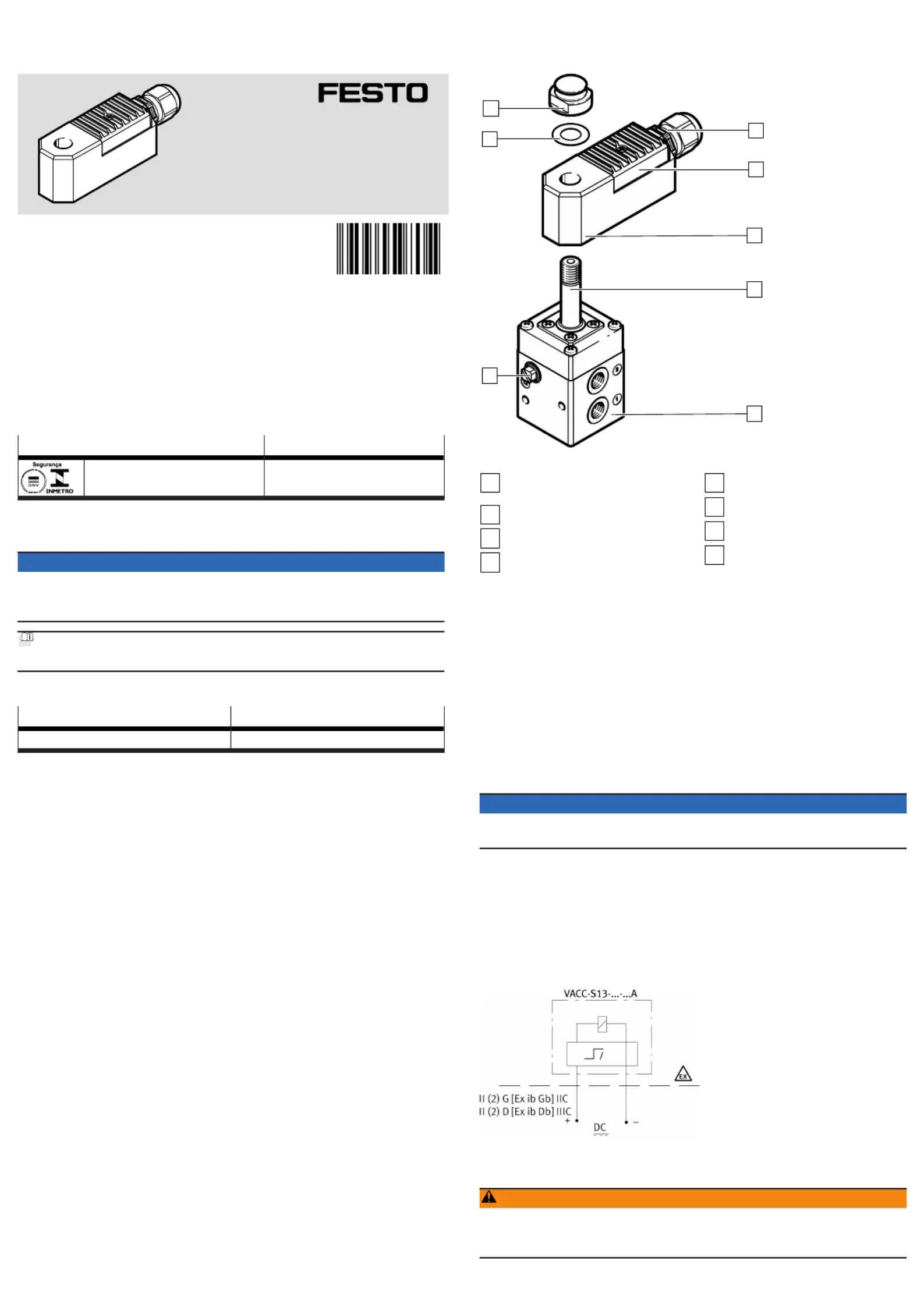
Fig. 1:Product design
1
Port 12 (only with external pilot
air supply)
2
Spring washer
3
Vent screw/retaining nut
4
Cable fitting with cap nut and
reducer
5
Cover, terminal housing
6
Solenoid coil
7
Armature guide tube
8
Solenoid valve
6.1Mechanical system
Prevent the cable fitting from unscrewing when loosening the cap nut. Note the
tightening torque: cable fitting 2.3 Nm; cap nut 1.5 Nm
1.
Push the solenoid coil and spring washer over the armature guide tube.
–
Sealing compound points to the solenoid valve.
2.
Tighten vent screw. Twisting the solenoid coil is no longer possible (tightening
torque 4…6Nm).
3.
Open the cover of the clamping housing.
4.
Connect electrical cables to the terminals. Note polarity (tightening torque
2…3Nm).
5.
Close the cover of the clamping housing (tightening torque 0.6…0.7Nm).
6.
With external pilot air supply use port12.
7.
Seal unused openings with blanking plugs or slot covers.
NOTICE
The surface coating of the solenoid valves is electrically non-conductive.
•Include the device in the system equipotential bonding.
6.2Electrical
1.Use only a cable with outside diameter 7…13mm for the installed M20 x 1.5
cable fitting.
2.Note polarity.
3.
To avoid ingress of water, tighten fitting and lock ring with an open-ended
spanner until the sealing force is sufficient.
4.
Use strain relief.
Electrical connection diagram
Fig.2
7
Commissioning
WARNING
Risk of injury from touching hot surfaces.
Contact with housing of the solenoid coil can cause burn injuries.
•Do not touch the housing.
Termékspecifikációk
| Márka: | Festo |
| Kategória: | nincs kategorizálva |
| Modell: | VACC-S13-11-K4-1-NM4A |
Szüksége van segítségre?
Ha segítségre van szüksége Festo VACC-S13-11-K4-1-NM4A, tegyen fel kérdést alább, és más felhasználók válaszolnak Önnek
Útmutatók nincs kategorizálva Festo

30 Március 2025
30 Március 2025
30 Március 2025
30 Március 2025
30 Március 2025
30 Március 2025
30 Március 2025
30 Március 2025
30 Március 2025
30 Március 2025
Útmutatók nincs kategorizálva
Legújabb útmutatók nincs kategorizálva
10 Április 2025
10 Április 2025
10 Április 2025
9 Április 2025
9 Április 2025
9 Április 2025
9 Április 2025
9 Április 2025
9 Április 2025
9 Április 2025