Használati útmutató Festo NPE-50
Festo
nincs kategorizálva
NPE-50
Olvassa el alább 📖 a magyar nyelvű használati útmutatót Festo NPE-50 (2 oldal) a nincs kategorizálva kategóriában. Ezt az útmutatót 12 ember találta hasznosnak és 6.5 felhasználó értékelte átlagosan 4.3 csillagra
Oldal 1/2
Montageanleitung (Original: de)
748153 / 2012-01b
†‡
Notpuffer
NPE-...
Festo SE & Co. KG
Postfach
D-73726 Esslingen
++49/(0)711/347-0
www.festo.com
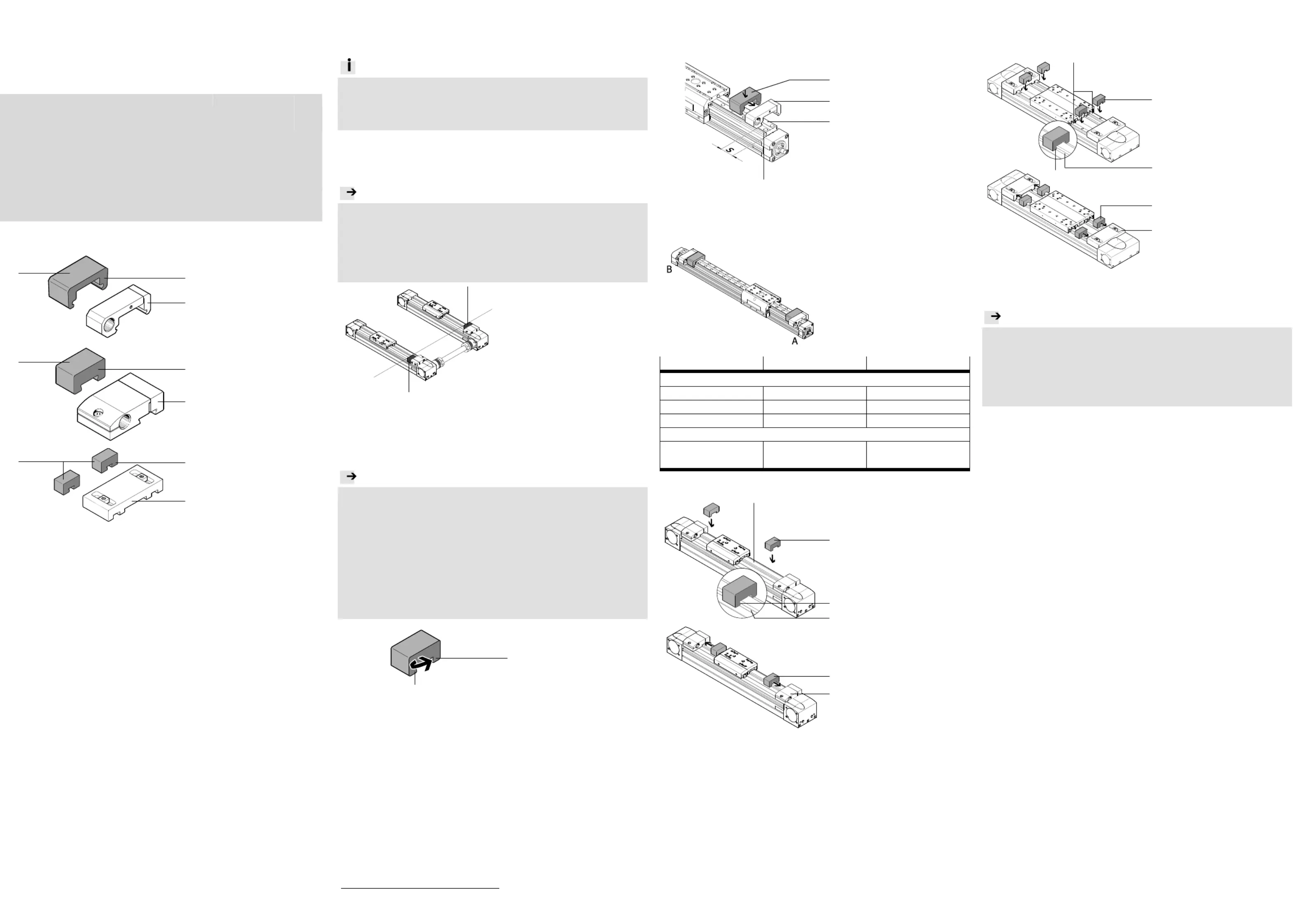
1. Teileliste
12296_12
Bei Achse DGE-...- -GK/ KF
FDG-...:
1 Notpuffer (1x)
NPE- /-25/-32/-40/- 18 63
4 Abdeckfolie (1x)
5 Stoßdämpferhalter (1x)
KYP- ...
12296_1
Bei Achse EGC-...-KF/EGC- -... FA
2 Notpuffer (1x)
NPE-50/-80/-120/-1 85
4 Abdeckfolie (1x)
6 Stoßdämpferhalter (1x)
KYE- ...
12296_13
Bei Achse EGC- -... HD
3 Notpuffer (2x)
NPE-125/-160/- 220
4 Abdeckfolie (2x)
7 Halter (1x)
EAYH- - -N L2 ...
Bestimmungsgemäß dienen die Notpuffer zur Verhinderung von 1… 3
Sachschaden infolge fehlerhafter Inbetriebnahme oder Programmierfehlern.
Sie dienen nicht als ständiges Dämpfungselement.
2. Allgemeine Hinweise
2a. Arbeitshub
Info
Zur Befestigung der Notpuffer 1 3 … :
Beachten Sie die mitgelieferten Montageanleitungen der Halter 5… 7.
Der nachträgliche Einbau von Notpuffern reduziert den Arbeitshub. 1… 3
Prüfen Sie, ob der verbleibende Arbeitshub für Ihre Anwendung ausreicht.
Arbeitshub = Nutzhub minus Notpuffer
2b. Gekoppelte Achsen
Hinweis
Bei Betrieb zweier gekoppelter Achsen:
Nur gleichmäßiges Anschlagen auf beiden Seiten bewirkt Belastungen ohne
Verwindung.
Stellen Sie sicher, dass Dämpfungselemente der gleichen Art
(Notpuffer oder Stoßdämpfer) an der gleichen Position auf Füh-1… 3
rungs- d Antriebsachsen angebracht werden. un
12296_8
3. Vorbereitung zur Montage
Entfetten Sie die vorgesehene Fläche der Halter zum Ankleben des 5… 7
Notpuffers mit einem milden Reinigungsmittel (z. B. Wasch-1… 3
benzin).
Hinweis
Die Abdeckfolie ist funktionsbedingt silikonbeschichtet und somit 4
LABS
1)
-haltig.
Die Silikone liegen in gebundener Form vor und werden durch das Berühren
der Abdeckfolie in der Regel nicht übertragen. Durch den Kontakt mit Lö-
sungsmitteln werden die Silikone herausgelöst.
Beachten Sie beim Abziehen der Abdeckfolie folgendes: 4
–jeglichen Kontakt der Abdeckfolie mit Lösungsmitteln vermeiden.4
–Abdeckfolie sofort aus dem kritischen Bereich entfernen. 4
Bei Einhaltung dieser Vorsichtsmaßnahmen ist der Notpuffer 1… 3 in mon-
tiertem Zustand LABS
1)
-frei.
12296_2
Ziehen Sie die Abdeck-
folie ab. 4
Montieren Sie den Halter 5… 7 gemäß mitgelieferter Montageanleitung.
1)
LABS = Lackbenetzungsstörende Substanzen
4. Montage
4a. Bei DGE- - -GK / FDG- ... KF ...
12296_6
Positionieren Sie den Stoß-
dämpferhalter je nach 5
Achsentyp mit Abstand s
( Tabelle).
Drücken Sie die Notpuf-
fer auf die Füh-1
rungsschiene (B) bis die Na-
sen (A) in die Profilrillen (C)
einschnappen.
Drücken Sie die Notpuf-
fer mit der Klebefläche 1
gegen die Stoßdämpferhal-
ter . 5
12296_7
Definition:
A = Motor-Seite
B = Abschlussseite
Achsentyp
Befestigungsseite
Abstand s
Antriebsachse
DGE- -...- - - 18 SP KF GK
A
≥ 7 mm
DGE- -...- - - 18 SP KF GK
B
≥ 0 mm
DGE-...- KF
A + B
≥ 0 mm
Führungsachse
FDG-...
−
auf gleicher Höhe wie bei
der Antriebsachse
4b. Bei EGC- -KF/EGC- - ... ... FA
12296_3
Drücken Sie die Not f-pu
fer auf die Führungs-2
schiene (B), bis die Na-
sen (A) in die Profilrillen (C)
einschnappen.
12296_4
Drücken Sie die Notpuf-
fer mit der Klebefläche 2
gegen die Stoßdämpferhal-
ter . 5
4c. Bei EGC- - - / - HD ... TB BS
12296_ 10
Drücken Sie die Notpuf-
fer auf die Führungs-3
schienen (B), bis die Na-
sen (A) in die Profilrillen (C)
einschnappen.
12296_ 11
Drücken Sie die Notpuf-
fer mit der Klebefläche3
gegen die Halter . 7
5. Lagerung und Transport
Hinweis
Lagern Sie den Notpuffer unter folgenden Bedingungen: 1… 3
–Raumtemperatur (18 25°C) …
– Luftfeuchtigkeit normal (40 … 60%)
–In einem luftdurchlässigen Behälter, ohne Weichmacher (keine Beutel oder
Tüten).
–Geschützt vor starker Lichteinstrahlung.
B
C
2
A
4
1
B
C
3
A
7
3
1
4
5
4
6
2
1
5
4
7
3
B
3
A
C
1 3 …
1 3 …
Termékspecifikációk
| Márka: | Festo |
| Kategória: | nincs kategorizálva |
| Modell: | NPE-50 |
Szüksége van segítségre?
Ha segítségre van szüksége Festo NPE-50, tegyen fel kérdést alább, és más felhasználók válaszolnak Önnek
Útmutatók nincs kategorizálva Festo

30 Március 2025
30 Március 2025
30 Március 2025
30 Március 2025
30 Március 2025
30 Március 2025
30 Március 2025
30 Március 2025
30 Március 2025
30 Március 2025
Útmutatók nincs kategorizálva
- Karran
- Reloop
- Masport
- Pro-User
- BMAX
- BabyGO
- Earbreeze
- Enhanced Flight
- Jenn-Air
- Siemens
- Kyoritsu
- Kendall Howard
- Constructa
- Alfatron
- Woodland Scenics
Legújabb útmutatók nincs kategorizálva
10 Április 2025
10 Április 2025
10 Április 2025
9 Április 2025
9 Április 2025
9 Április 2025
9 Április 2025
9 Április 2025
9 Április 2025
9 Április 2025