Használati útmutató Edimax GS-5416PLC
Olvassa el alább 📖 a magyar nyelvű használati útmutatót Edimax GS-5416PLC (222 oldal) a kapcsoló kategóriában. Ezt az útmutatót 4 ember találta hasznosnak és 2 felhasználó értékelte átlagosan 4.5 csillagra
Oldal 1/222

GS GS-5416PLC / -5424 CPL
User Manual
11 2020 1.- / v 1

CONTENTS
I Introducon .......................................................................................... 1
I-1 Overview ....................................................................................................... 1
I-2 Package Content ............................................................................................ 1
I-3 Features ......................................................................................................... 2
I-4 Product Componen ts ..................................................................................... 2
I-4-1 Ports ........................................................................................................ 2
I-4-2 LED Indicators ......................................................................................... 3
II Installaon ............................................................................................ 4
II-1 Mounng the Switch ..................................................................................... 4
II-1-1 Placement Tips ........................................................................................ 4
II-1-2 Desktop Mounng .................................................................................. 5
II-1-3 Rack Mounng ........................................................................................ 5
III Geng Started 7.....................................................................................
III-1 Connecng to Power ..................................................................................... 7
III-2 Connecng to Network ................................................................................. 8
III-3 Power over Ethernet (PoE) Consideraons ................................................... 9
III-4 Starng the Web-based Conguraon Utility ............................................. 10
III-4-1 Logging In .............................................................................................. 12
III-4-2 Logging Out ........................................................................................... 13
IV Web-based Switch Conguraon .......................................................... 15
IV-1 Status ........................................................................................................... 16
IV-1-1 System Informaon .............................................................................. 16
IV-1-2 Logging Message ................................................................................... 18
IV-1-3 Port ....................................................................................................... 19
IV-1-4 Link Aggregaon ................................................................................... 24
IV-1-5 MAC Address Table ............................................................................... 25
IV-2 Network ....................................................................................................... 26
IV-2-1 IP Address ............................................................................................. 26
IV-2-2 System Time ......................................................................................... 29
IV-3 Port .............................................................................................................. 31
IV-3-1 Port Seng ........................................................................................... 31
IV-3-2 Long Range Mode ................................................................................. 34
IV-3-3 Error Disable ......................................................................................... 35
IV-3-4 Link Aggregaon ................................................................................... 36

IV-3-5 Jumbo Frame ........................................................................................ 43
IV-4 PoE ............................................................................................................... 44
IV-4-1 Global Seng ....................................................................................... 44
IV-4-2 Priority Seng ...................................................................................... 46
IV-4-3 Power Limit ........................................................................................... 47
IV-4-4 PoE Status ............................................................................................. 49
IV-4-5 PD (Powered Device) Alive Check ......................................................... 50
IV-5 VLAN ............................................................................................................ 52
IV-5-1 VLAN ..................................................................................................... 52
IV-5-2 Voice VLAN ........................................................................................... 60
IV-5-3 MAC VLAN ............................................................................................ 63
IV-6 MAC Address Table ..................................................................................... 66
IV-6-1 Dynamic Address .................................................................................. 66
IV-6-2 Stac Address ....................................................................................... 66
IV-6-3 Filtering Address ................................................................................... 67
IV-7 Spanning Tree .............................................................................................. 68
IV-7-1 Property ................................................................................................ 68
IV-7-2 Port Seng ........................................................................................... 70
IV-7-3 MST Instance ........................................................................................ 72
IV-7-4 MST Port Seng ................................................................................... 74
IV-7-5 Stascs ................................................................................................ 76
IV-8 Discovery ..................................................................................................... 78
IV-8-1 LLDP ...................................................................................................... 78
IV-9 Mulcast ..................................................................................................... 95
IV-9-1 General ................................................................................................. 95
IV-9-2 IGMP Snooping ................................................................................... 100
IV-9-3 MVR .................................................................................................... 107
IV- Security10 ...................................................................................................... 112
IV- -1 RADIUS10 ......................................................................................... 112
IV- -2 Management Access10 .................................................................... 115
IV- -3 Authencaon Manager10 .............................................................. 121
IV- -4 Port Security10 ................................................................................. 131
IV- -5 Protected Port10 .............................................................................. 133
IV- -6 Storm Control10 ............................................................................... 135
IV- -7 DoS10 ............................................................................................... 137
IV- -8 DHCP Snooping10 ............................................................................ 141
IV IP- -910 Source Guard ............................................................................ 149
IV-11 ACL ............................................................................................................. 154
IV- -1 MAC ACL11 ....................................................................................... 154
IV- -2 MAC ACE11 ...................................................................................... 155
IV- -3 IPv4 ACL11 ....................................................................................... 157

IV- -4 IPv4 ACE11 ....................................................................................... 158
IV- -5 ACL Binding11 .................................................................................. 162
IV- QoS12 ............................................................................................................ 164
IV- -1 General12 ......................................................................................... 164
IV- -2 Rate Lim12 it ..................................................................................... 172
IV- Diagnoscs13 ................................................................................................ 175
IV- -1 Logging13 ......................................................................................... 175
IV- -2 Mirroring13 ...................................................................................... 177
IV- -3 Ping13 .............................................................................................. 179
IV- -4 Traceroute13 .................................................................................... 180
IV- -5 er Test13 Copp .................................................................................. 181
IV- -6 Fiber Module13 ................................................................................ 182
IV- -7 UDLD13 ............................................................................................ 183
IV- Management14 ............................................................................................. 186
IV- -1 User Account14 ................................................................................ 186
IV- -2 Fireware14 ....................................................................................... 188
IV- -3 Conguraon14 ............................................................................... 192
IV- -4 SNMP14 ........................................................................................... 196
1
I Introducon
Thank you for choosing a Edimax (PoE) WEB Smart Ethernet Switch. This device is
designed to be operaonal right out- -the-box as a standard bridge. In the default of
conguraon, it will forward packets between connecng devices aer powered up.
Before you begin installing the switch, make sure you have all of the package contents
available, and a PC with a web browser for using web-based system management tools.
I-1 Overview
The Edimax GS-54XXPLC Series Smart Switch features 4 RJ45 and 4 SFP Combo ports The .
GS- PLC and GS- PLC come with 5416 5424 16 and Gigabit PoE+ ports respecvely. 24
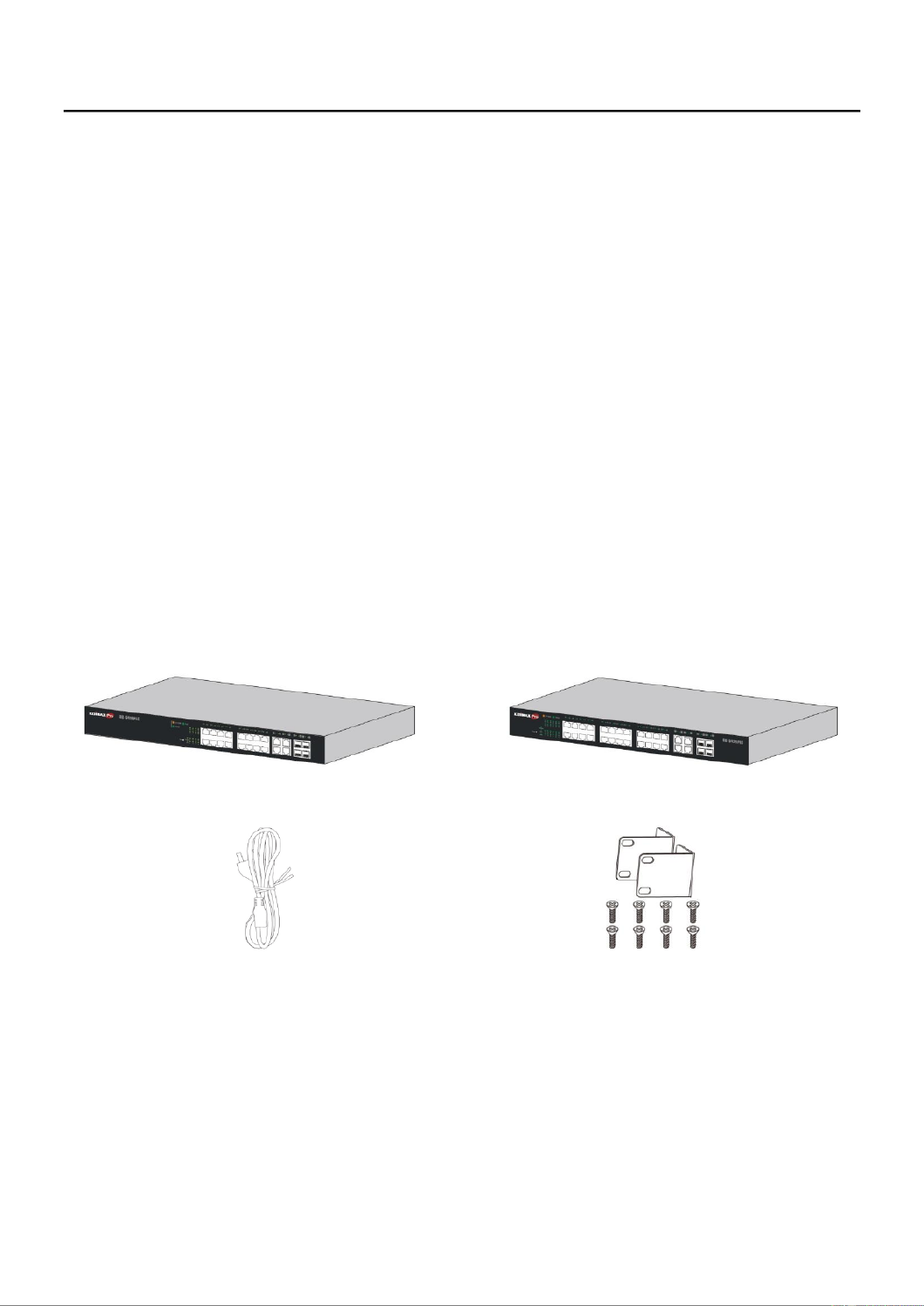
I-2 Package Content
Before using the product, check that the items listed below are included and in good
condion. If any item does not accord with the table, please contact your dealer
immediately.
or
1
2
3
1. GS-5416PLC Switch
OR
GS-5424PLC tch Swi
2. Power Cord
3. Rack-Mount Kit & Screws
2
I-3 Features
Supports up to 24 10/100/1000Mbps Gigabit Ethernet ports and 4 SFP slots or 4
mini-GBIC/SFP slots
IEEE 802.3af/at PoE compliant to simplify deployment and installation
GS-5416PLC supports PoE up to 30W per port with W total power budget330 .
Available PoE power output budget is 280W
GS-5424PLC supports PoE up to 30W per port with 450W total power budget.
Available PoE power output budget is 400W
Automacally detects powered devices (PD) and power consumpon levels
IEEE 802.1Q VLAN network segmentaon to enhance performance and security for
Supports Access Control List (ACL)
Switch capacity: PG28CB: 56Gbps, Forwarding rate: 41.6Mbps
Supports IGMP Snooping V1 / V2 / V3
8K MAC address table and 10K jumbo frames
19-inch rack-mountable metal case
I-4 Product Components
I-4-1 Ports
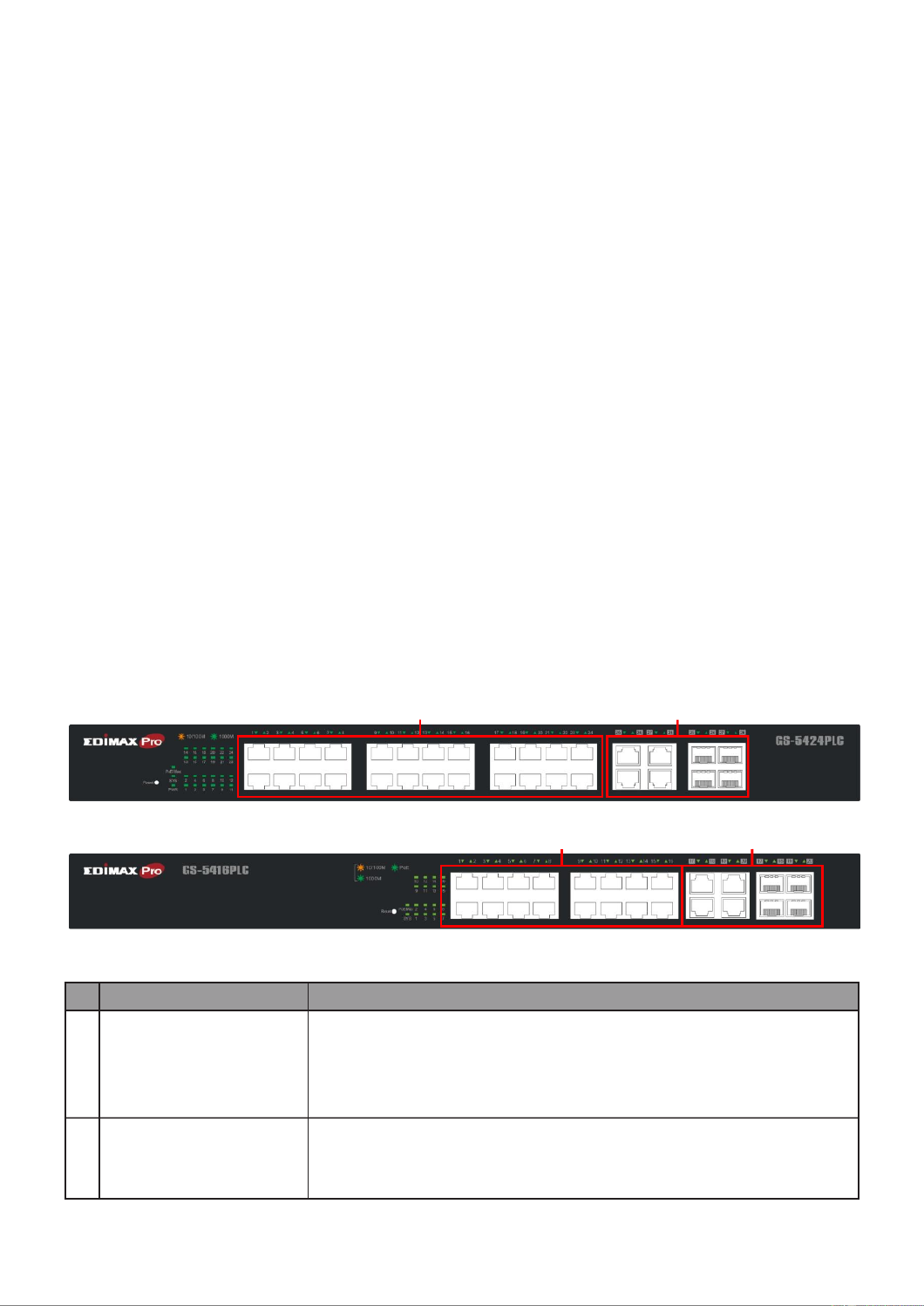
The following are the front views of the switches.
Figure 1 –GS-5424PLC Front View
Figure 2 –GS-5416PLC Front View
No.
Name
Descripon
1
10/100/1000Mbps
RJ-45 ports
1- for GS-5424PLC 24
1-16 for GS-5416PLC
Designed to connect to network devices with a bandwidth of
10Mbps, 100Mbps or 1000Mbps. Each has a corresponding
10/100/1000Mbps LED.
2
RJ45/ combo Ports SFP
(SFP1, SFP2, SFP3, and
SFP4)
Designed to install SFP modules or RJ- connect to network 45
devices with a bandwidth of 1000Mbps. Each has a
corresponding 1000Mbps LED.
1
2
1
2

3
The following is the rear view of the switches:
Figure 3 - Rear View
No.
Name
Descripon
1
AC power in
Support AC100 240V 50-60Hz. –
I-4-2 LED Indicators
The following are the front views of the switches.
Figure 4 -5424PLC Front View LED Indicators –GS
Figure 5 -5416PLC Front View LED Indicators –GS
No.
Name
Descripon
1
Power
O: power o
On: power on
2
System
O: system not ready
On: system ready
Blinking: system boot- up
3
PoE LED
O: PoE inacve
On: PoE acve
4
Port LED
O: port disconnected or link fail
Green on: 1000Mbs connected
Amber on: 10/100Mbs connected
Blinking: sending or receiving data
5
Combo Port LED
O: port disconnected or link fail
Green on: 1000Mbs connected
1
1
5
5
2
3
1
2
3
4
4

4
II Installaon
This chapter describes how to install and connect your Edimax Switch. Read the following
topics and perform the procedures in the correct order. Incorrect installation may cause
damage to the product.
Please note, since the installation / mounng instrucons for dierent models of
switches are almost idencal -5424PLC is used as the graphical demonstraons here. , GS
II-1 Mounng the Switch
There are two ways to physically set up the switch.
Place the switch on a at surface.
Mount the switch in a standard rack (1 rack unit high).
II-1-1 Placement Tips
Ambient Temperature To prevent the switch from overheang, do not operate it —
in an area that exceeds an ambient temperature of 122°F (50°C).
Air Flow Be sure that there is adequate air ow around the switch. —
Mechanical Loading Be sure that the switch is level and stable to avoid any —
hazardous condions.
Circuit Overloading Adding the switch to the power outlet must not overload that —
circuit.
Follow these guidelines to install the switch securely.
Put the switch in a stable place such as a desktop, to avoid it falling.
Ensure the switch works in the proper AC input range and matches the voltage
labeled.
Ensure there is proper heat dissipaon from and adequate venlaon around the
switch.
Ensure the switch’s locaon can support the weight of the switch and its accessories.

5
II-1-2 Desktop Mounng
Please install the four rubber feet (included) on the boom of the switch and place the
switch at the desired locaon.
Figure 6 - Desktop Installaon
II-1-3 Rack Mounng
You can mount the switch in any standard size, 19-inch (about 48 cm) wide rack. The
switch requires 1 rack unit (RU) of space, which is 1.75 inches (44.45 mm) high.
For stability, load the rack from the boom to the top, with the heaviest devices on the
boom. A top-heavy rack is likely to be unstable and may p over.
When mounng smaller switch products into a standard 19-inch rack, a pair of extension
brackets (somemes referred to as ears) are needed to adapt the switch to the rack size.
These extension brackets are mounted on the switch using the screws provided in the kit,
and have two holes that are used to then screw the switch into the rack.
An example of one type of these extension brackets is shown in the following gure.
A common problem that occurs during rack mounng is the distance between the screw
holes on the rack. Some racks are made with a uniform distance between all of the holes,
and others have the holes organized into groups (see photo on the next page for an
example).
When organized into groups, the switch must be placed in the rack so that the holes in
the extension brackets line up correctly.

6
1. Align the mounng brackets with the mounng holes on the switch’s side panels
and secure the brackets with the screws provided.
Figure 7 - Rack Mounng Bracket Installaon –
2. Secure the switch on the equipment rack with the screws provided.
Figure 8 - Rack Mounng Rack Installaon –

7
III Geng Started
This secon provides an introducon to the web-based conguraon ulity, and covers
the following topics:
Powering on the device
Connecng to the network
Power over Ethernet (PoE) consideraons
Starng the web-based conguraon ulity
III-1 Connecng to Power
Power down and disconnect the power cord before servicing or wiring a switch.
Do not disconnect modules or cabling unless the power is rst switched o. The device
only supports the voltage outlined in the type plate. Do not use any other power
components except those specically designated for the switch.
Disconnect the power cord before installaon or cable wiring.
The switch is powered by the AC 100-240 V 50/60Hz internal high-performance power
supply. It is recommended to connect the switch with a single-phase three-wire power
source with a neutral outlet, or a mulfunconal computer professional source.
Connect the AC power connector on the back panel of the switch to the external power
source with the included power cord, and check the power LED is on.
Figure 9 - Rear View AC Power Socket
8
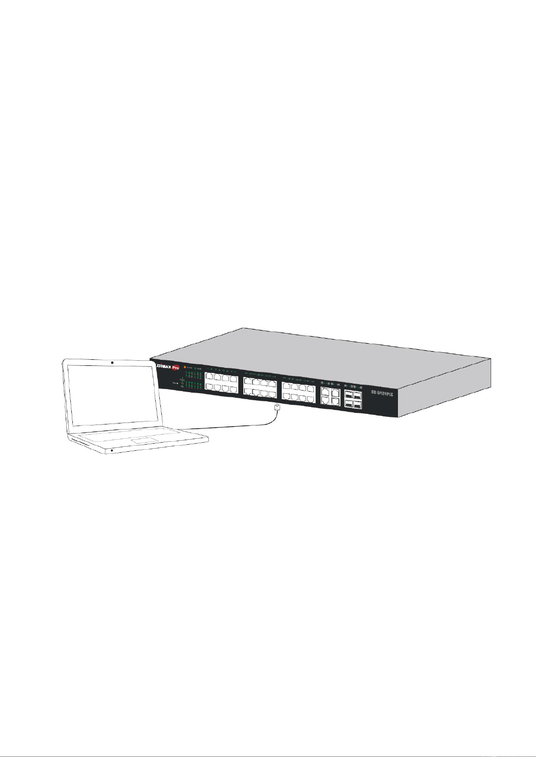
III-2 Connecng to Network
To connect the switch to the network:
1. Connect an Ethernet cable to the Ethernet port of a computer
2. Connect the other end of the Ethernet cable to one of the numbered Ethernet
ports of the switch. The LED of the port lights if the device connected is acve.
3. Repeat Step 1 and Step 2 for each device to connect to the switch.
We strongly recommend using CAT-5E or beer cable to connect network devices. When
connecng network devices, do not exceed the maximum cabling distance of 100 meters
(328 feet). It can take up to one minute for aached devices or the LAN to be operational
aer it is connected. This is normal behavior.
Connect the switch to end nodes using a standard Cat 5/5e Ethernet cable (UTP/STP) to
connect the switch to end nodes as shown in the illustraon below.
Switch ports will automacally adjust to the characteriscs (MDI/MDI-X, speed, duplex)
of the device to which the switch is connected.
Figure - PC Connect 10

9
III-3 Power over Ethernet (PoE) Consideraons
Devices considered a Power Sourcing Equipment (PSE), can support up to 30 Was per
PoE port to a Powered Device (PD).
Model
Power Dedicated to PoE
PoE Ports
PoE Standard Supported
GS- PLC 5416
280W
1 to 16
IEEE802.3at/af
GS- 4PLC 542
400W
1 to 24
IEEE802.3at/af
Ports 1-16 of GS-5416PLC and ports 1- of GS-5424PLC provide PoE power supply 24
funconality with a maximum output power up to 30W each port. This can supply power
to PDs such as internet phones, network cameras, wireless access points. Connect the
switch PoE port directly to the PD port using a network cable.
When connecng switches capable of supplying PoE, consider the following informaon:
Switch models with PoE funcon are PSEs. These models are capable of supplying DC
power to aached PDs, such as VoIP phones, IP cameras, and wireless access points
(APs). PoE switches. Addionally, PoE switches are capable of detecng and
supplying power to pre-standard legacy PoE Power Devices. Due to the support for
legacy PoE, there is a possibility that PoE switches acng as a PSE may inadvertently
detect and supply power an aached PSE, including other PoE switches. This false
detecon may result in a PoE switch operang improperly and unable to supply
power to aached PDs.
The prevenon of a false detecon can be easily remedied by disabling PoE on the
ports that are used to connect PSEs. Another simple pracce to prevent a false
detecon is to rst power up a PSE device before connecng it to a PoE switch.
When a device is falsely detected as a PD, disconnect the device from the PoE port
and power recycle the device with AC power before reconnecng it to the PoE port.

10
III-4 Starng the Web-based Conguraon Ulity
This secon describes how to navigate the web-based switch conguraon ulity.
Be sure to disable any pop-up blocker.
Browser Restricons
If you are using older versions of Internet Explorer, you cannot directly use an IPv6
address to access the device. You can, however, use the DNS (Domain Name System)
server to create a domain name that contains the IPv6 address, and then use that
domain name in the address bar in place of the IPv6 address.
If you have mulple IPv6 interfaces on your management staon, use the IPv6 global
address instead of the IPv6 link local address to access the device from your browser.
Launching the Conguraon Ulity
To open the web-based conguraon ulity:
1. Open a Web browser.
2. Enter the IP address of the device you are conguring in the address bar on the
browser (factory default IP address is 192.168.2.1) and then press Enter.
When the device is using the factory default IP address, its power LED ashes
connuously. When the device is using a DHCP assigned IP address or an
administrator-congured stac IP address, the power LED is lit a solid color. Your
computer’s IP address must be in the same subnet as the switch. For example, if the
switch is using the factory default IP address, your computer’s IP address can be in the
following range: 192.168.2.x (whereas x is a number from 2 to 254).
Aer a successful connecon, the login window displays.
Figure - -5416PLC Login Window 11 GS

11
Figure - -5416PLC Login Window 12 GS
Please note that, unless otherwise specied, pictures / interfaces of
GS-5424PLC will be used hereaer in the document.

12
III-4-1 Logging In
Note: Unless otherwise specied, pictures / interfaces of
GS-5424PLC will be used hereaer in the document.
The default username is admin and the default password is . The rst me that you 1234
log in with the default username and password, you are required to enter a new
password.
To log in to the device conguraon ulity:
1. Enter the default user ID (admin) and the default password (1234 ).
2. If this is the rst me that you logged on with the default user ID (admin) and the
default password (1234) it is recommended that you change your password
immediately. See IV-14 Management on page 186 for addional informaon.
When the login aempt is successful, the System Informaon window displays.

13
Figure - System Informaon 13
If you entered an incorrect username or password, an error message appears and the
Login page remains displayed on the window. If you are having problems logging in,
please see the Launching the Conguraon Ulity secon in the Administraon Guide for
addional informaon.
III-4-2 Logging Out
By default, the applicaon logs out aer ten minutes of inacvity.
To manually logout, click Logout in the top right corner of any page.
When a meout occurs or you intenonally log out of the system, a message appears and
the Login page appears, with a message indicang the logged-out state. Aer you log in,
the applicaon returns to the inial page.

14

15
IV Web-based Switch Conguraon
The PoE smart switch soware provides rich Layer 2 funconality for switches in your
networks. This chapter describes how to use the web-based management interface (Web
UI) to congure the switch’s features.
For the purposes of this manual, the user interface is separated into four secons, as
shown in the following gure:
Figure - User Interface 14
No.
Name
Descripon
1
Conguraon menu
Navigate to locate specic switch funcons.
2
Conguraon sengs
Edit specic funcon sengs.
3
Switch’s current link
status
Green squares indicate the port link is up, while black squares
indicate the port link is down.
4
Common toolbar
Provides access to frequently used sengs.
2
1
3
4
16
IV-1 Status
Use the Status pages to view system informaon and status.
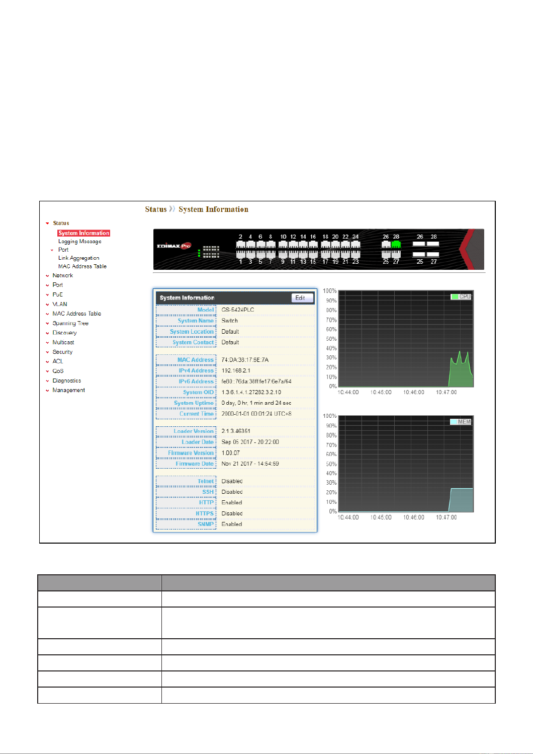
IV-1-1 System Informaon
This page shows switch panel, CPU ulizaon, Memory ulization and other system
current informaon. It also allows user to edit some system informaon.
To display the Device Informaon web page, click Status > System Informaon.
Figure - Status > System Informaon 15
Item
Descripon
Model
Model name of the switch.
System Name
System name of the switch. This name will also use as CLI prex
of each line. (“Switch>” or “Switch#”).
System Locaon
Locaon informaon of the switch.
System Contact
Contact informaon of the switch.
MAC Address
Base MAC address of the switch.
IPv4 Address
Current system IPv4 address.

17
System OID
SNMP system object ID.
System Upme
Total elapsed me from boong.
Current Time
Current system me.
Loader Version
Boot loader image version.
Loader Date
Boot loader image build date.
Firmware Version
Current running rmware image version.
Firmware Date
Current running rmware image build date.
Telnet
Current Telnet service enable/disable state.
SSH
Current SSH service enable/disable state.
HTTP
Current HTTP service enable/disable state.
HTTPS
Current HTTPS service enable/disable state.
SNMP
Current SNMP service enable/disable state.
Click “Edit” buon on the table tle to edit following system informaon.
Figure - Status > System Informaon > Edit System Informaon 16
Item
Descripon
System Name
System name of the switch. This name will also use as CLI prex
of each line. (“Switch>” or “Switch#”).
System Locaon
Locaon informaon of the switch.
System Contact
Contact informaon of the switch.

18
IV-1-2 Logging Message
To view the logging messages stored on the RAM and Flash, click Status > Logging
Message.
Figure - Status > Logging Message 17
Item
Descripon
Log ID
The log idener.
Time
The me stamp for the logging message.
Severity
The severity for the logging message.
Descripon
The description of logging message.
Viewing
RAM: Show the logging messages stored on the RAM.
Flash: Show the logging messages stored on the Flash.
Clear
Clear the logging messages.
Refresh
Refresh the logging messages.

19
IV-1-3 Port
IV-1-3-1 Stascs
This page displays standard counters on network trac form the Interfaces, Ethernet
-like and RMONMIB. Interfaces and Ethernet-like counters display errors on the trac
passing through each port. RMON counters provide a total count of dierent frame types
and sizes passing through each port. The “Clear” buon will clear MIB counter of current
selected port.
To display the Port Flow Chart web page, click Status > Port > Stascs.

20

21
Figure - Status > Port > Stascs 18
Item
Descripon
Port
Select one port to show counter statiscs.
MIB Counter
Select the MIB counter to show dierent counter type
All: All counters.
Interface: Interface related MIB counters.
Etherlike: Ethernet-like related MIB counters.
RMON: RMON related MIB counters.
Refresh Rate
Refresh the web page every period of seconds to get new
counter of specied port.
22
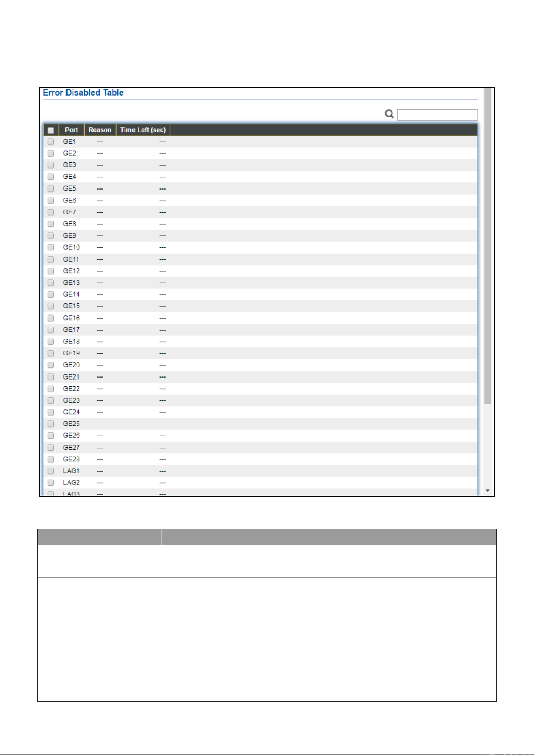
IV-1-3-2 Error Disabled
To display the Error Disabled web page, click Status > Port > Error Disabled.
Figure - Status > Port > Error Disabled 19
Item
Descripon
□
Select one or more port to operate.
Port
Interface or port number.
Reason
Port will be disabled by one of the following error reason:
BPDU Guard
UDLD
Self Loop
Broadcast Flood
Unknown Mulcast Flood
Unicast Flood
ACL

23
Port Security Violaon
DHCP rate limit
ARP rate limit
Time Le (sec)
The me le in second for the error recovery.
Refresh
Refresh the current page.
Recover
Recover the selected port status.
IV-1-3-3 Bandwidth Ulizaon
This page allows user to browse ports’ bandwidth ulization in real me. This page will
refresh automacally in every refresh period.
To display Bandwidth Ulizaon web page, click Status > Port > Bandwidth Ulizaon.
Figure - Status > Port > Bandwidth Ulizaon 20
Item
Descripon
Refresh Rate
Refresh the web page every period of seconds to get new
bandwidth ulizaon data.
24
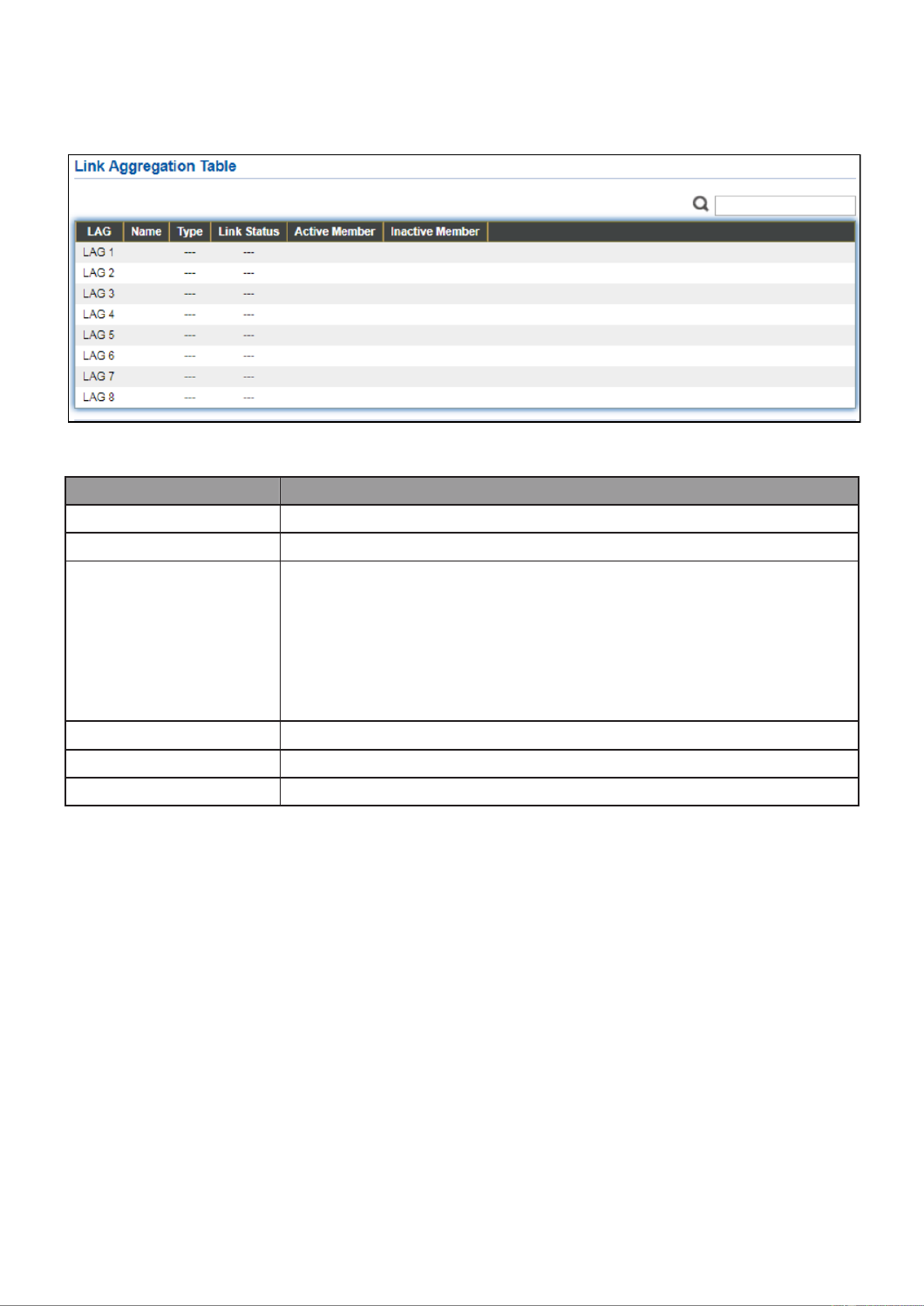
IV-1-4 Link Aggregaon
To display the Link Aggregaon web page, click Status > Link Aggregaon.
Figure - Status > Link Aggregaon 21
Item
Descripon
LAG
LAG Name.
Name
LAG port description.
Type
The type of the LAG.
Stac: The group of ports assigned to a stac LAG are always
acve members.
LACP: The group of ports assigned to dynamic LAG are
candidate ports. LACP determines which candidate ports
are acve member ports.
Link Status
LAG port link status.
Acve Member
Acve member ports of the LAG.
Inacve Member
Inacve member ports of the LAG.

25
IV-1-5 MAC Address Table
The MAC address table page displays all MAC address entries on the switch including
stac MAC address created by administrator or auto learned from hardware. The “Clear”
buon will clear all dynamic entries and “Refresh” buon will retrieve latest MAC
address entries and show them on page.
To display the MAC Address Table web page, click Status > MAC Address Table.
Figure - Status > MAC Address Table 22
Item
Descripon
VLAN
VLAN ID of the mac address.
MAC Address
MAC address.
Type
The type of MAC address
Management: DUT’s base mac address for management Purpose.
Stac: Manually congured by administrator
Dynamic: Auto learned by hardware.
Port
The type of Port
CPU: DUT’s CPU port for management purpose.
Other: Normal switch port.

26
IV-2 Network
Use the Network pages to congure sengs for the switch network interface and how
the switch connects to a remote server to get services.
IV-2-1 IP Address
This secon allows you to edit the IP address, Netmask, Gateway and DNS server of the
switch.
To view the IP Address menu, navigate to Network > IP Address.

27
Figure - Network > IP Address 23
Item
Descripon
Address Type
The address type of switch IP conguraon including
Stac: Stac IP congured by users will be used.
Dynamic: Enable the DHCP to obtain the IP address from a
DHCP server.
IP Address
Specify the switch stac IP address on the stac conguraon.
Subnet Mask
Specify the switch subnet mask on the stac conguraon.
Default Gateway
Specify the default gateway on the stac conguraon. The

28
default gateway must be in the same subnet with switch IP
address configuration.
DNS Server 1
Specify the primary user-defined IPv4 DNS server configuration.
DNS Server 2
Specify the secondary user-defined IPv4 DNS server
configuration.
Table 3-2: IPv6 Address fields
IPv4 Address
The operational IPv4 address of the switch.
IPv4 Gateway
The operational IPv4 gateway of the switch.
IPv6 Address v6
The operational IPv6 address of the switch.
IPv6 Gateway
The operational IPv6 gateway of the switch.
Link Local Address
The IPv6 link local address for the switch.
29
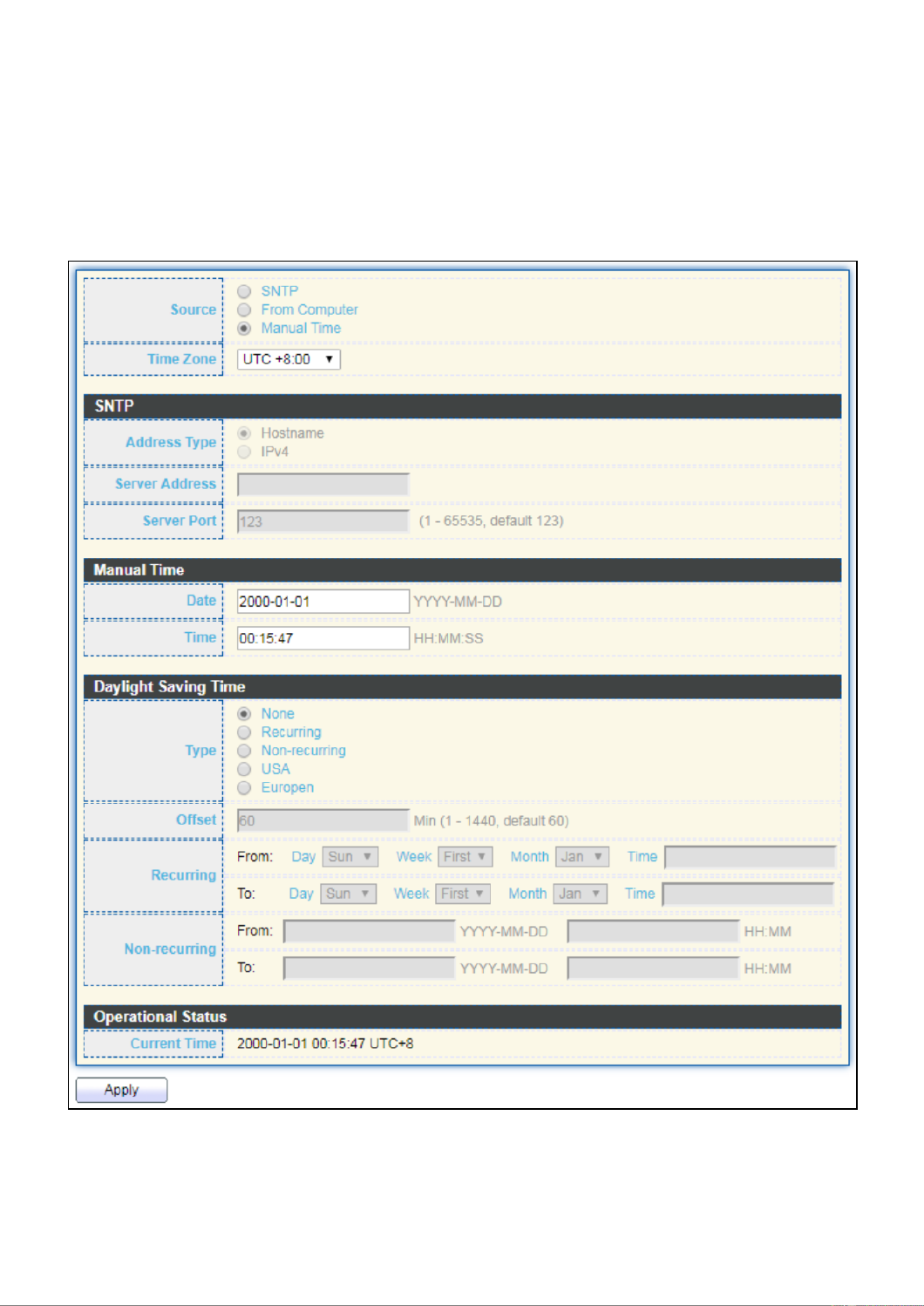
IV-2-2 System Time
This page allows user to set time source, static time, time zone and daylight saving
settings. Time zone and daylight saving takes effect both static time or time from SNTP
server.
To display System Time page, click Network > System Time.
Figure - Network > System Time 24

30
Item
Descripon
Source
Select the me source.
SNTP: Time sync from NTP server.
From Computer: Time set from browser host.
Manual Time: Time set by manually congure.
Time Zone
Select a me zone dierence from lisng district.
SNTP
Address Type
Select the address type of NTP server. This is enabled when me
source is SNTP.
Server Address
Input IPv4 address or hostname for NTP server. This is enabled
when me source is SNTP.
Server Port
Input NTP port for NTP server. Default is 123. This is enabled
when me source is SNTP.
Manual Time
Date
Input manual date. This is enabled when me source is manual.
Time
Input manual me. This is enabled when me source is manual.
Daylight Saving Time
Type
Select the mode of daylight saving me.
Disable: Disable daylight saving me.
Recurring: Using recurring mode of daylight saving me.
Non-Recurring: Using non-recurring mode of daylight saving
me.
USA: Using daylight saving me in the United States that
starts on the second Sunday of March and ends on the rst
Sunday of November.
European: Using daylight saving me in the Europe that
starts on the last Sunday in March and ending on the last
Sunday in October.
Oset
Specify the adjust oset of daylight saving me.
Recurring From
Specify the starng me of recurring daylight saving me. This
eld available when selecng “Recurring” mode.
Recurring To
Specify the ending me of recurring daylight saving me. This
eld available when selecng “Recurring” mode.
Non-recurring From
Specify the starng me of non-recurring daylight saving me.
This eld available when selecng “Non Recurring” mode.-
Non-recurring To
Specify the ending me of recurring daylight saving me. This
eld available when selecng “Non Recurring” mode.-
Non-recurring From
Specify the starng me of non-recurring daylight saving me.
This eld available when selecng “ Recurring” mode.Non-
Non recurring To
Specify the ending me of recurring daylight saving me. This
eld available when selecng “Non Recurring” mode.-
31
IV-3 Port
Use the Port pages to congure sengs for switch port related features.
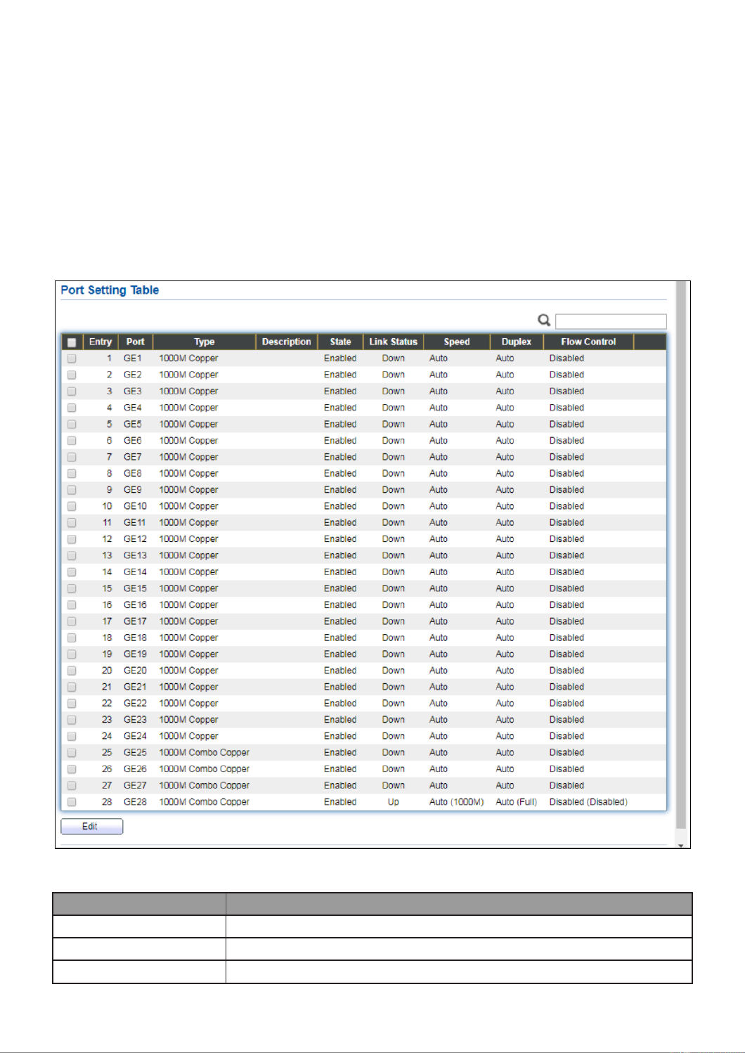
IV-3-1 Port Seng
This page shows port current status and allow user to edit port conguraons. Select port
entry and click “ ” buon to edit port conguraons.Edit
To display Port Seing web page, click . Port > Port Seng
Figure - Port > Port Seng 25
Item
Descripon
Port
Port Name.
Type
Port media type.
Descripon
Port Descripon.

32
State
Port admin state
Enabled: Enable the port.
Disabled: Disable the port.
Link Status
Current port link status
Up: Port is link up.
Down: Port is link down.
Speed
Current port speed conguraon and link speed status.
Duplex
Current port duplex conguraon and link duplex status.
Flow Control
Current port ow control conguraon and link ow control
status.
Click “ ” buon toEdit edit Port Seng menu
Figure - Port > Port Seng > Port Seng 26
Item
Descripon
Port
Selected Port list.
Descripon
Port media type.
State
Port admin state.
Enabled: Enable the port.
Disabled: Disable the port.
Speed
Port speed capabilies.
Auto: Auto speed with all capabilies.
Auto-10M: Auto speed with 10M ability only.

33
Auto-100M: Auto speed with 100M ability only.
Auto-1000M: Auto speed with 1000M ability only.
Auto-10M/100M: Auto speed with 10M/100M abilies.
10M: Force speed with 10M ability.
100M: Force speed with 100M ability.
1000M: Force speed with 1000M ability.
Duplex
Port duplex capabilies.
Auto: Auto duplex with all capabilies.
Half: Auto speed with 10M and 100M ability only.
Full: Auto speed with 10M/100M/1000M ability only.
Flow Control
Port ow control.
Auto: Auto ow control by negoaon.
Enabled: Enable ow control ability.
Disabled: Disable ow control ability.

34
IV-3-2 Long Range Mode
This page shows port current status and Enable long range mode will double the cabling
distance but reduce the speed to 10Mbps.
To display Long Range Mode web page, click Port > Long Range Mode Seng.
Figure - Port > Long Range Mode 27

35
IV-3-3 Error Disable
To display Error Disabled web page, click Port > Error Disabled
Figure - Port > Error disable 28
Item
Descripon
Recover Interval
Auto recovery aer this interval for error disabled port.
BPDU Guard
Enabled to auto shutdown port when BPDU Guard reason occur. This
reason caused by STP BPDU Guard mechanism.
UDLD
Enabled to auto shutdown port when UDLD violaon occur.
Self Loop
Enabled to auto shutdown port when Self Loop reason occur.
Broadcast Flood
Enabled to auto shutdown port when Broadcast Flood reason occur.
This reason caused by broadcast rate exceed broadcast storm control
rate.
Unknown Mulcast
Flood
Enabled to auto shutdown port when Unknown Mulcast Flood
reason occur. This reason caused by unknown mulcast rate exceed
unknown mulcast storm control rate.
Unicast Flood
Enabled to auto shutdown port when Unicast Flood reason occur.
This reason caused by unicast rate exceed unicast storm control rate.
ACL
Enabled to auto shutdown port when ACL shutdown port reason
occur. This reason caused packet match the ACL shutdown port
acon.
Port Security
Enabled to auto shutdown port when Port Security Violaon reason
occur. This reason caused by violaon port security rules.
DHCP rate limit
Enabled to auto shutdown port when DHCP rate limit reason occur.
This reason caused by DHCP packet rate exceed DHCP rate limit.

36
ARP rate limit
Enabled to auto shutdown port when ARP rate limit reason occur.
This reason caused by DHCP packet rate exceed ARP rate limit.
IV-3-4 Link Aggregaon
IV-3-4-1 Group
This page allows user to congure link aggregaon group load balance algorithm and
group member.
To view the Group menu, navigate to Port > Link Aggregaon > Group.
Figure - Port > Link Aggregaon > Group 29
Item
Descripon
Load Balance
Algorithm
LAG load balance distribuon algorithm
src-dst-mac: Based on MAC address.
src-dst-mac-ip: Based on MAC address and IP address.
LAG
LAG Name.
Name
LAG port description.
Type
The type of the LAG
Stac: The group of ports assigned to a stac LAG are always
acve members.
LACP: The group of ports assigned to dynamic LAG are
candidate ports. LACP determines which candidate ports are
acve member ports.
Link Status
LAG port link status

37
Acve Member
Acve member ports of the LAG.
Inacve Member
Inacve member ports of the LAG.
Click “ ” to edit Link Aggregaon Group menu.Edit
Figure - Port > Link Aggregaon > Group > Edit Link Aggregation Group 30
Item
Descripon
LAG
Selected LAG group ID.
Name
LAG port description.
Type
The type of the LAG
Stac: The group of ports assigned to a stac LAG are always
acve members.
LACP: The group of ports assigned to dynamic LAG are
candidate ports. LACP determines which candidate ports are
acve member ports.
Member
Select available port to be LAG group member port.

38
IV-3-4-2 Port Seng
This page shows LAG port current status and allow user to edit LAG port conguraons.
Select LAG entry and click “ ”Edit buon to edit LAG port conguraons.
To display LAG Port Seng web page, click Port > Link Aggregaon > Port Setng.
Figure - Port > Link Aggregaon > Port Seng 31
Item
Descripon
LAG
LAG Port Name.
Type
LAG Port media type.
Descripon
LAG Port description.
State
LAG Port admin state
Enabled: Enable the port.
Disabled: Disable the port.
Link Status
Current LAG port link status
Up: Port is link up.
Down: Port is link down.
Speed
Current LAG port speed conguraon and link speed status.
Duplex
Current LAG port duplex conguraon and link duplex status.
Flow Control
Current LAG port ow control conguraon and link ow control
status.

39
Click “ ” to view Edit Port Seng menu.Edit
Figure - Port > Link Aggregaon > Port Seng > Edit Port Seng 32
Item
Descripon
Port
Selected Port list.
Descripon
Port descripon.
State
Port admin state
Enabled: Enable the port.
Disabled: Disable the port.
Speed
Port speed capabilies
Auto: Auto speed with all capabilies.
Auto-10M: Auto speed with 10M ability only.
Auto-100M: Auto speed with 100M ability only.
Auto-1000M: Auto speed with 1000M ability only.
Auto-10M/100M: Auto speed with 10M/100M abilies.
10M: Force speed with 10M ability.
100M: Force speed with 100M ability.
1000M: Force speed with 1000M ability.
Flow Control
Port ow control
Auto: Auto ow control by negoaon.
Enabled: Enable ow control ability.
Disabled: Disable ow control ability.

40
IV-3-4-3 LACP
This page allows user to congure LACP global and port conguraons. Select ports and
click “ ” buon to edit port conguraon.Edit
To display the LACP Seng web page , click Port > Link Aggregaon > LACP.
Figure - Port > Link Aggregaon > LACP 33
Item
Descripon
System Priority
Congure the system priority of LACP. This decides the system
priority eld in LACP PDU.
Port
Port Name.
Port Priority
LACP priority value of the port.
Timeout
The periodic transmissions type of LACP PDUs.
Long: Transmit LACP PDU with slow periodic (30s).
Short: Transmit LACPP DU with fast periodic (1s).
41
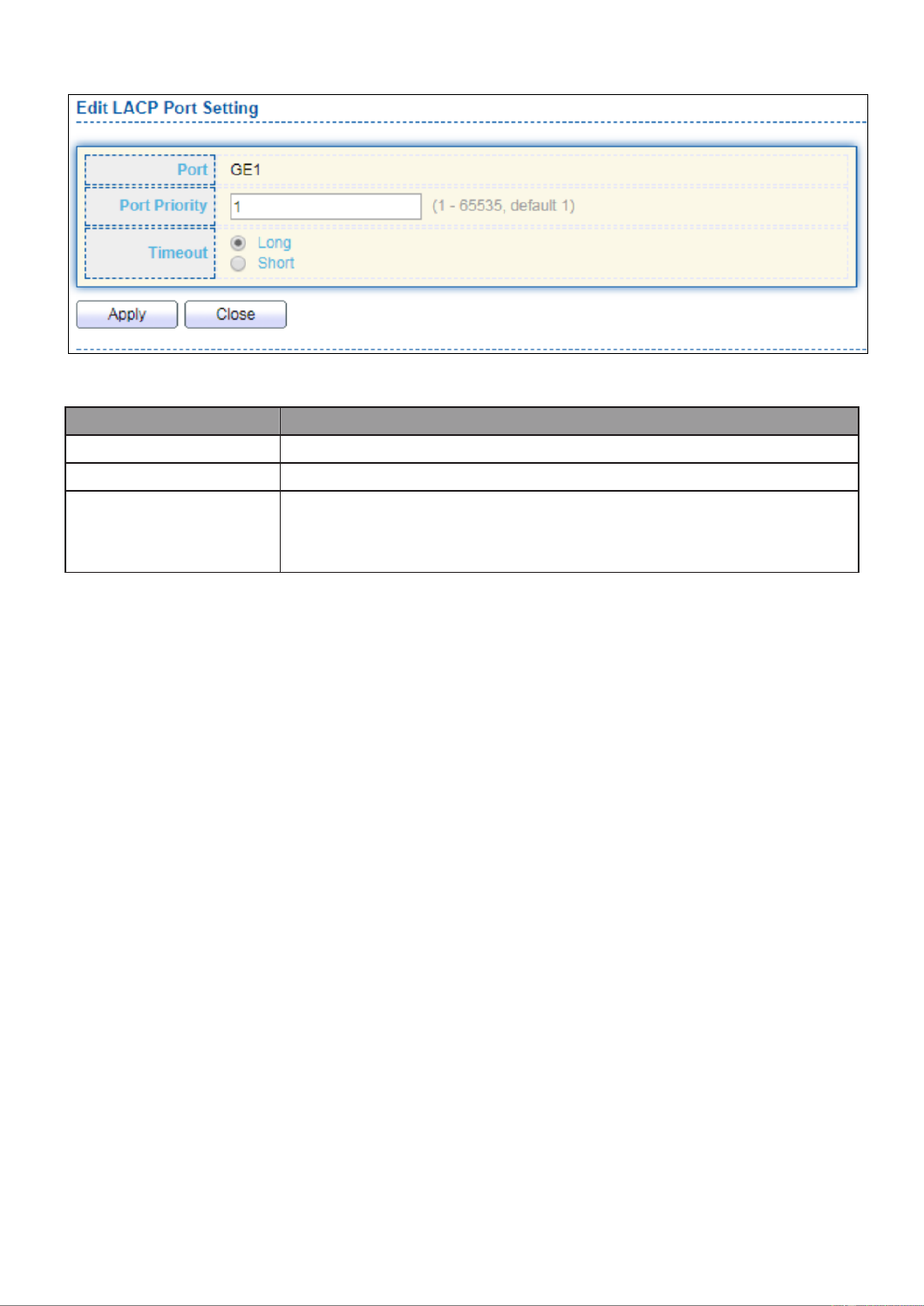
Click " " buon to view Edit LACP Port Seng menu. Edit
Figure - Port > Link Aggregaon > LACP > Edit LACP Port Seng 34
Item
Descripon
Port
Selected port list.
Port Priority
Enter the LACP priority value of the port
Timeout
The periodic transmissions type of LACP PDUs.
Long: Transmit LACP PDU with slow periodic (30s).
Short: Transmit LACPP DU with fast periodic (1s).

42
IV-3-4-4 EEE
This page allows user to congure Energy Ecient Ethernet sengs.
To display the EEE web page, click . Port > EEE
Figure - Port > EEE 35
Item
Descripon
Port
Port Name.
State
Port EEE admin state
Enabled: EEE is enabled.
Disabled: EEE is disabled.
Operaonal Status
Port EEE operaonal status
Enabled: EEE is operang.
Disabled: EEE is no operang.

43
Click “ ” to edit the EEE menu.Edit
Figure - Port > EEE > Edit EEE Seing 36
Item
Descripon
Port
Port Name
State
Port EEE admin state
Enabled: EEE is enabled.
Disabled: EEE is disabled.
IV-3-5 Jumbo Frame
This page allows user to congure switch jumbo frame size.
To display Jumbo Frame web page, click Port > Jumbo Frame.
Figure - Port > Jumbo Frame 37
Item
Descripon
Jumbo Frame
Enable or disable jumbo frame. When jumbo frame is enabled,
switch max frame size is allowed to congure. When jumbo frame is
disabled, default frame size 1522 will be used.

44
IV-4 PoE
Port security can set port isolaon and specic behavior.
IV-4-1 Global Seng
To display the Global web page, click PoE > Global Seng.
Figure - PoE > Global Seng 38

45
Item
Descripon
Nominal Power
Maximum supply power.
Consuming Power
Current consumed power.
Remaining Power
Remaining available power.
Schedule Status
Schedule status global switch.
Name
PoE Schedule Name.
Port List
The ports provide power in designated schedule index.
Schedule Status
The current schedule status.
Click “ ” to view PoE Schedule List menu.Edit
Figure - PoE > Priority Seng > Edit PoE Schedule Edit 39
Item
Descripon
Index
The serial number of schedule list.
Schedule Status
Schedule Status
Checked: Schedule status is enabled.
Unchecked: Schedule status is disabled.
Name
Enter the PoE schedule name.
Date
Select a valid me for this schedule.
Port List
Select the port provide power.

46
IV-4-2 Priority Seng
Use this secon to set the power supply priority of PoE ports. Individual ports can be
assigned crical, high, or low power supply priority.
To display the Priority Seng web page, click PoE > Priority Setng.
Figure - PoE > Priority Seng 40
Click the port to change its priority status according to the boom right hand chart.
47
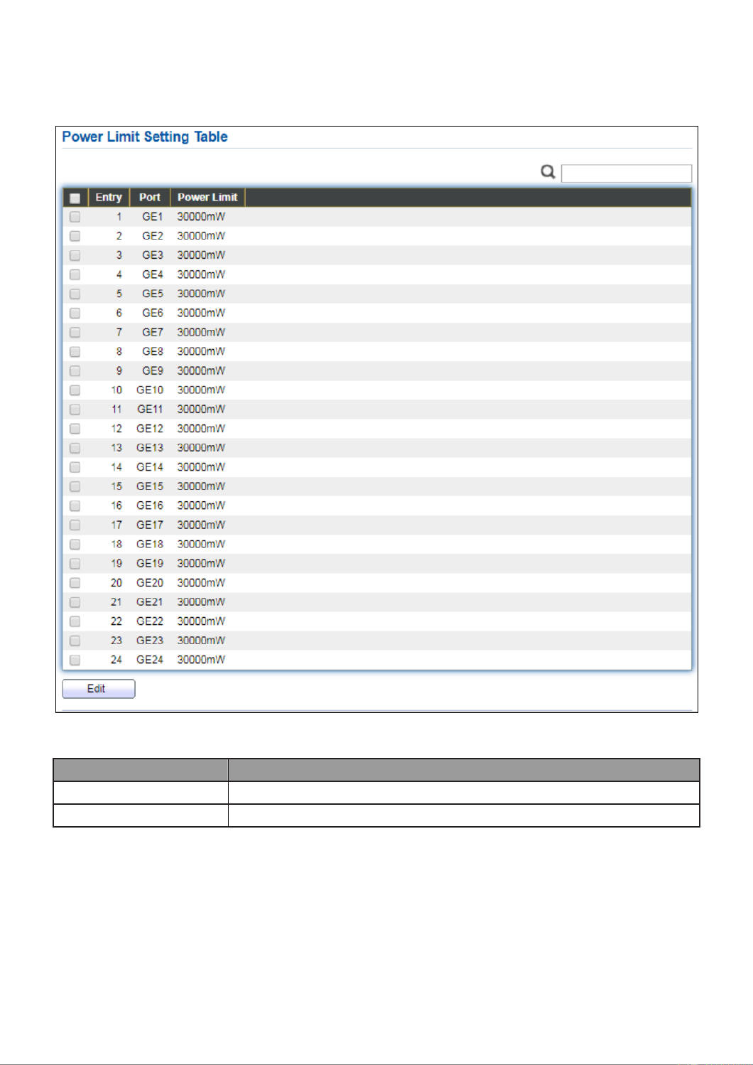
IV-4-3 Power Limit
To display the Power Limit web page, click PoE > Power Limit.
Figure - PoE > Power Limit 41
Item
Descripon
Port
Port name.
Power Limit
The max supply power for this port.
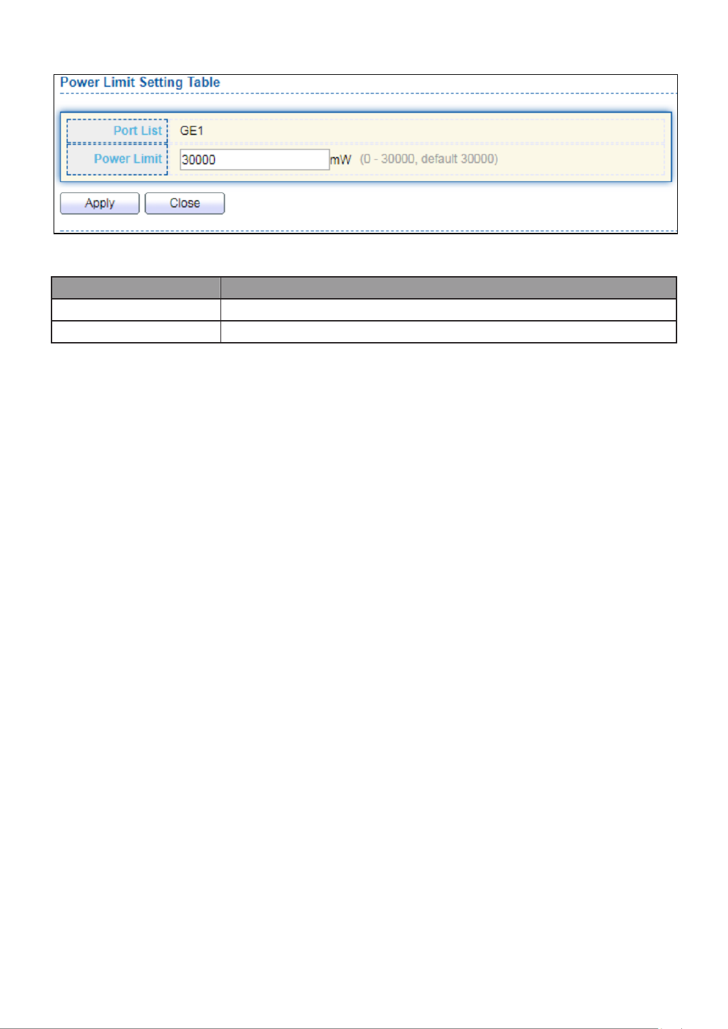
48
Click “ ” to view Power Limit Seing menu.Edit
Figure - PoE > Power Seng > Power Limit Seing Table 42
Item
Descripon
Port List
Selected port list.
Power Limit
Enter max supply power value for the selected port list.
49
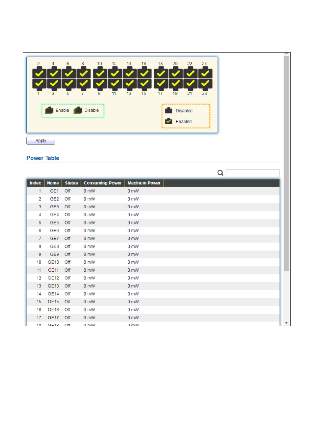
IV-4-4 PoE Status
To display the PoE Status web page, click PoE > Power Status.
Figure - PoE > Power Stauts 43
Per Port PoE Status
Checked: Port PoE status is enabled.
Unchecked: Port PoE status is disabled.

50
IV-4-5 PD (Powered Device) Alive Check
To display the PD Alive Check web page, click PoE > PD Alive Check.
Figure - PoE > PD Alive Check 44
Click “ ” buon to view Edit Edit PD Alive Check menu.
Figure - PoE > PD Alive Check > Edit PD Alive Check 45

51
Item
Descripon
Port List
Port name.
Status
Check to enable PD Alive Check.
Ping PD IP Address
IP address of connected device.
Interval Time
The me interval of how long the system issues a ping request to the
connected PD to check if the device is dead or alive.
Time range is 10-300 seconds.
Retry Count
This column allows users to set how many mes the system retries
issuing a ping request to the PD. Aer the retries and fails, the
system will carry out the Action below. “ ”
For example, if Retry Count is set to 2, and the system nds the “ ”
device dead, the system will try 2 ping requests. If the 2 retries fail, re
the system will carry out the Acon . “ ”
Acon
The acon taken if the retry count reaches the set number:
None: No acon.
Alarm: The switch issues an alarm message via Syslog.
PD Reboot: The switch reboots the PoE port.
Reboot & Alarm: The switch reboots the PoE port and issue an
alarm message via Syslog.
Reboot Time
Set a reboot me between 30-180 seconds.
Due to many kinds PDs having dierent reboot me, please be of
aware of how long they will nish boong up.
The system will check the PD again aer the reboot me. If you are
unsure of the boot up me it is recommended to set it longer. ,

52
IV-5 VLAN
A virtual local area network, virtual LAN or VLAN, is a group of hosts with a common set
of requirements that communicate as if they were aached to the same broadcast
domain, regardless of their physical locaon. A VLAN has the same aributes as a
physical local area network (LAN), but it allows for end staons to be grouped togeth-er
even if they are not located on the same network switch. VLAN membership can be
congured through soware instead of physically relocang devices or connecons.
IV-5-1 VLAN
Use the VLAN pages to congure sengs of VLAN.
IV-5-1-1 Create VLAN
This page allows user to add or delete VLAN ID entries and browser all VLAN entries that
add stacally or dynamic learned by GVRP. Each VLAN entry has a unique name, user can
edit VLAN name in edit page.
To display Create VLAN page, click . VLAN > VLAN > Create VLAN
Figure - VLAN > VLAN > Create VLAN 46
Item
Descripon
Available VLAN
VLAN has not created yet.
Select available VLANs from le box then move to right box to
add.

53
Created VLAN
VLAN had been created.
Select created VLANs from right box then move to le box to
delete
VLAN
The VLAN ID.
Name
The VLAN Name.
Type
The VLAN Type.
Stac: Port base VLAN.
Dynamic: 802.1q VLAN.
Click “ ” buon to view Edit VLAN Name menu.Edit
Figure - VLAN > VLAN > Create VLAN > Edit VLAN Name 47
Item
Descripon
Name
Input VLAN name.

54
IV-5-1-2 VLAN Conguraon
This page allows user to congure the membership for each port of selected VLAN.
To display VLAN Configuraon page, click VLAN > VLAN > VLAN Conguraon.
Figure - VLAN > VLAN > VLAN Conguraon 48
Item
Descripon
VLAN
Select specied VLAN ID to congure VLAN conguraon.
Port
Display the interface of port entry.
Mode
Display the interface VLAN mode of port.
Membership
Select the membership for this port of the specied VLAN ID.
Forbidden: Specify the port is forbidden in the VLAN.

55
Excluded: Specify the port is excluded in the VLAN.
Tagged: Specify the port is tagged member in the VLAN.
Untagged: Specify the port is untagged member in the VLAN.
PVID
Display if it is PVID of interface.
IV-5-1-3 Membership
This page allows user to view membership informaon for each port and edit
membership for specied interface.
To display Membership page, click VLAN > VLAN > Membership.
Figure - VLAN > VLAN > Membership 49

56
Item
Descripon
Port
Display the interface of port entry.
Mode
Display the interface VLAN mode of port.
Administrave
VLAN
Display the administrave VLAN list of this port.
Operaonal
VLAN
Display the operational VLAN list of this port. Operaonal VLAN means
the VLAN status that really runs in device. It may dierent to
administrave VLAN.
Click " " buon to view the Edit Port Seng menu Edit
Figure - VLAN > VLAN > Membership > Edit Port Seing 50
Item
Descripon
Port
Display the interface.
Mode
Display the VLAN mode of interface.
Membership
Select VLANs of le box and select one of following membership then move
to right box to add membership. Select VLANs of right box then move to le
box to remove membership. Tagging membership may not choose in dier
VLAN port mode. Select the me source.
Forbidden: Set VLAN as forbidden VLAN.
Excluded: This opon is always disabled.
Tagged: Set VLAN as tagged VLAN.
Untagged: Set VLAN as untagged VLAN.
PVID: Check this checkbox to select the VLAN ID to be the port-based

57
VLAN ID for this port. PVID may auto select or can’t select in dier
sengs.
IV-5-1-4 Port Seng
This page allows user to congure ports VLAN sengs such as VLAN port mode, PVID
etc…The aributes depend on dierent VLAN port mode.
To display Port Seing page, click VLAN > VLAN > Port Seng.
Figure - VLAN > VLAN > Port Seng 51

58
Item
Descripon
Port
Display the interface.
Mode
Display the VLAN mode of interface.
PVID
Display the Port-based VLAN ID of port.
Accept Frame Type
Display accept frame type of port.
Ingress Filtering
Display ingress lter status of port.
Uplink
Display uplink status.
TPID
Display TPID used of interface.
Click “ ” buon to Edit Port Seng menu.Edit
Figure - VLAN > VLAN > Port Seng > Edit Port Seing 52
Item
Descripon
Port
Display selected port to be edited.
Mode
Select the VLAN mode of the interface.
Forbidden: Set VLAN as forbidden VLAN.
Hybrid: Support all funcons as dened in IEEE 802.1Q specicaon.
Access: Accepts only untagged frames and join an untagged VLAN.
Trunk: An untagged member of one VLAN at most, and is a tagged
member of zero or more VLANs.
PVID
Specify the port-based VLAN ID (1- lable with Hybrid and 4094). It’s only avai
Trunk mode.
Accepted
Type
Specify the acceptable-frame-type of the specied interfaces. It’s only
available with Hybrid mode.
Ingress
Set checkbox to enable/disable ingress ltering. It’s only available with

59
Filtering
Hybrid mode.
Uplink
Set checkbox to enable/disable uplink mode. It’s only available with trunk
mode.
TPID
Select TPID used of interface. It’s only available with trunk mode.

60
IV-5-2 Voice VLAN
Use the Voice VLAN pages to congure sengs of Voice VLAN.
IV-5-2-1 Property
This page allows user to congure global and per interface sengs of voice VLAN.
To display Property Web page, click VLAN> Voice VLAN> Property.
Figure - VLAN > Voice VLAN > Property 53

61
Item
Descripon
State
Set checkbox to enable or disable voice VLAN funcon.
VLAN
Select Voice VLAN ID. Voice VLAN ID cannot be default VLAN.
Cos/802.1p
Select a value of VPT. Qualied packets will use this VPT value as inner
priority.
Remarking
Set checkbox to enable or disable 1p remarking. If enabled, qualied
packets will be remark by this value.
Aging Time
Input value of aging me. Default is 1440 minutes. A voice VLAN entry will
be age out aer this me if without any packet pass through.
Port Seng Table
Port
Display port entry.
State
Display enable/disabled status of interface.
Mode
Display voice VLAN mode.
QoS Policy
Display voice VLAN remark will eect which kind of packet.
Click “ ” buon to view Edit Port Seng menu.Edit
Figure - VLAN > Voice VLAN > Property > Edit Port Seng 54
Item
Descripon
Port
Display selected port to be edited.
State
Set checkbox to enable/disabled voice VLAN funcon of interface.
Mode
Select port voice VLAN mode
Auto: Voice VLAN auto detect packets that match OUI table and add
received port into voice VLAN ID tagged member.
Manual: User need add interface to VLAN ID tagged member
manually.
QoS Policy
Select port QoS Policy mode
Voice Packet: QoS aributes are applied to packets with OUIs in the
source MAC address.
All: QoS aributes are applied to packets that are classied to Voice
VLAN.
62
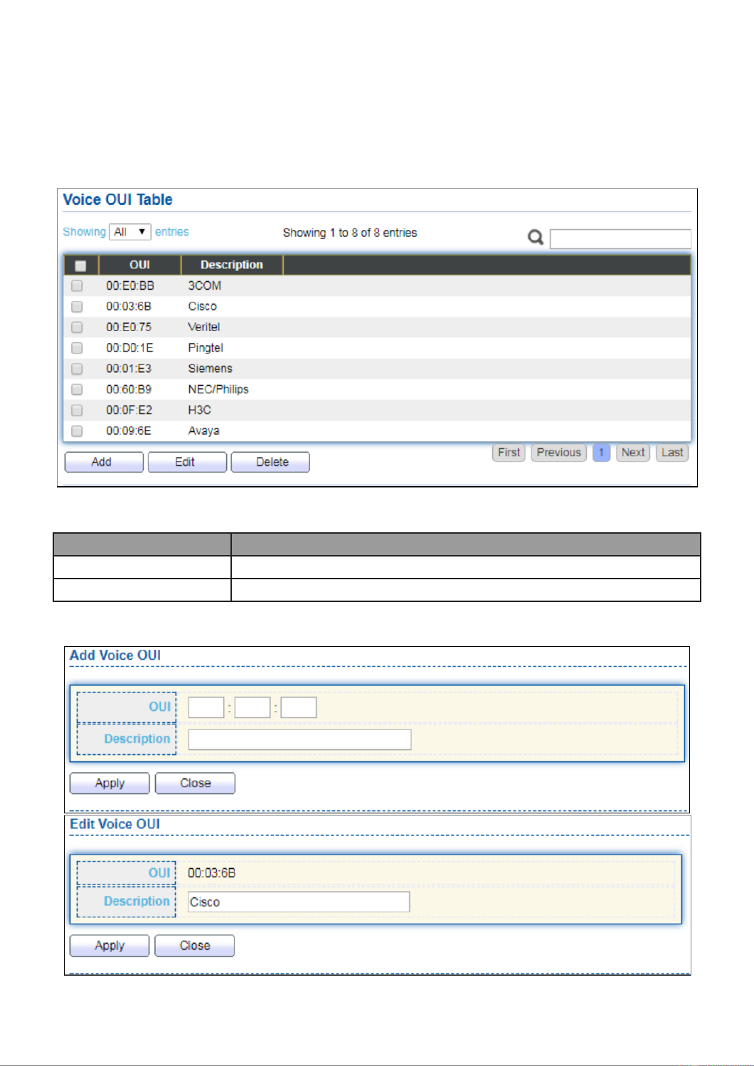
IV-5-2-2 Voice OUI
This page allows user to add, edit or delete OUI MAC addresses. Default has 8
pre-dened OUI MAC.
To display the Voice OUI Web page, click VLAN > Voice VLAN > Voice OUI.
Figure - VLAN > Voice VLAN > Voice OUI 55
Item
Descripon
OUI
Display OUI MAC address.
Descripon
Display descripon of OUI entry.
Click “Add” or “Edit” buon to Add/Edit Voice OUI menu.
Figure - VLAN > Voice VLAN > Voice OUI > Add/Edit Voice OUI 56

63
Item
Descripon
OUI
Input OUI MAC address. Can’t be edited in edit dialog.
Descripon
Input descripon of the specied MAC address to the voice VLAN
OUI table.
IV-5-3 MAC VLAN
Use the MAC VLAN pages to congure sengs of MAC VLAN.
IV-5-3-1 MAC Group
This page allows user to add or edit groups sengs of MAC VLAN.
To display the MAC page , click VLAN > MAC VLAN > MAC Group.
Figure - VLAN > MAC VLAN > MAC Group 57
Item
Descripon
Group ID
Display group ID of entry.
MAC Address
Display mac address of entry.
Mask
Display mask of mac address for classied packet.
Click “ ” buon or "Add Edit" buon to view Add/Edit MAC menu.

64
Figure - VLAN > MAC VLAN > MAC Group > Add/Edit MAC 58
Item
Descripon
Group ID
Input group ID that is a unique ID of mac group entry. The range
from 1 to 2147483647. Only available on Add Dialog.
MAC Address
Input mac address for classifying packets.
Mask
Input mask of mac address.
IV-5-3-2 Group Binding
This page allows user to bind MAC VLAN group to each port with VLAN ID.
To display Group Binding page, click VLAN> MAC VLAN > Group Binding .
Figure - VLAN > MAC VLAN > Group Binding 59

65
Item
Descripon
Port
Display port ID that binding with MAC group entry.
Group ID
Display group ID that port binding with.
VLAN
Display VLAN ID that assign to packets which match MAC group.
Click “ ” or “Add Edit” buon to view the Add/Edit Group Binding menu.
Figure - VLAN > MAC VLAN > Add/Edit Group Binding 60
Item
Descripon
Port
Select ports in le box then move to right to binding with MAC group. Or
select ports in right box then move to le to unbind with MAC group. Only
interface has hybrid VLAN mode can be selected and bound with protocol
group. Only available on Add dialog.
Group ID
Select a Group ID to associate with port. Only available on Add dialog.
VLAN
Input VLAN ID that will assign to packets which match MAC group.

66
IV-6 MAC Address Table
Use the MAC Address Table pages to show dynamic MAC table and congure sengs for
stac MAC entries.
IV-6-1 Dynamic Address
To display the Dynamic Address web page, click MAC Address Table > Dynamic Address.
Figure - MAC Address Table > Dynamic Address 61
Item
Descripon
Aging Time
The me in seconds that an entry remains in the MAC address
table. Its valid range is from 10 to 630 seconds, and the default
value is 300 seconds.
IV-6-2 Stac Address
To display the Stac Address web page, click MAC Address Table > Stac Address.
Figure - MAC Address Table > Stac Address 62

67
Item
Description
MAC Address
The MAC address to which packets will be stacally forwarded.
VLAN
Specify the VLAN to show or clear MAC entries.
Port
Interface or port number.
IV-6-3 Filtering Address
To display the Filtering Address web page, click MAC Address Table > Filtering Address.
Figure - MAC Address Table > Filtering Address 63
Item
Description
MAC Address
Specify unicast MAC address in the packets to be dropped.
VLAN
Specify the VLAN to show or clear MAC entries.

68
IV-7 Spanning Tree
The Spanning Tree Protocol (STP) is a network protocol that ensures a loop-free topology
for any bridged Ethernet local area network.
IV-7-1 Property
To display the Property web page, click Spanning Tree > Property.
Figure - Spanning Tree > Property 64

69
Item
Description
State
Enable/disable the STP on the switch.
Operation Mode
Specify the STP operation mode.
STP: Enable the Spanning Tree (STP) operation.
RSTP: Enable the Rapid Spanning Tree (RSTP) operation.
MSTP: Enable the Multiple Spanning Tree (MSTP) operation.
Path Cost
Specify the path cost method.
Long: Specifies that the default port path costs are within the
range: 1- 200,000,000.
Short: Specifies that the default port path costs are within the
range: 1- 65,535.
BPDU Handling
Specify the BPDU forward method when the STP is disabled.
Filtering: Filter the BPDU when STP is disabled.
Flooding: Flood the BPDU when STP is disabled.
Priority
Specify the bridge priority. The valid range is from 0 to 61440, and the
value should be the multiple of 4096. It ensures the probability that the
switch is selected as the root bridge, and the lower value has the higher
priority for the switch to be selected as the root bridge of the topology.
Hello Time
Specify the STP hello time in second to broadcast its hello message to
other bridges by Designated Ports. Its valid range is from 1 to 10
seconds.
Max Age
Specify the time interval in seconds for a switch to wait the
configuration messages, without attempting to redefine its own
configuration.
Forward Delay
Specify the STP forward delay time, which is the amount of time that a
port remains in the Listening and Learning states before it enters the
Forwarding state. Its valid range is from 4 to 10 seconds.
TX Hold Count
Specify the tx-hold-count used to limit the maximum numbers of
packets transmission per second. The valid range is from 1 to 10.
Region Name
The MSTP instance name. Its maximum length is 32 characters. The
default value is the MAC address of the switch.
Revision
The MSTP revision number. Its valid rage is from 0 to 65535.
Max Hop
Specify the number of hops in an MSTP region before the BPDU is
discarded. The valid range is 1 to 40.
Operational Status
Bridge Identifier
Bridge identifier of the switch.
Designated Root
Identifier
Bridge identifier of the designated root bridge.
Root Port
Operational root port of the switch.
Root Path Cost
Operational root path cost.
Topology Change
Count
Numbers of the topology changes.
70
Last Topology
Change
The last time for the topology change.
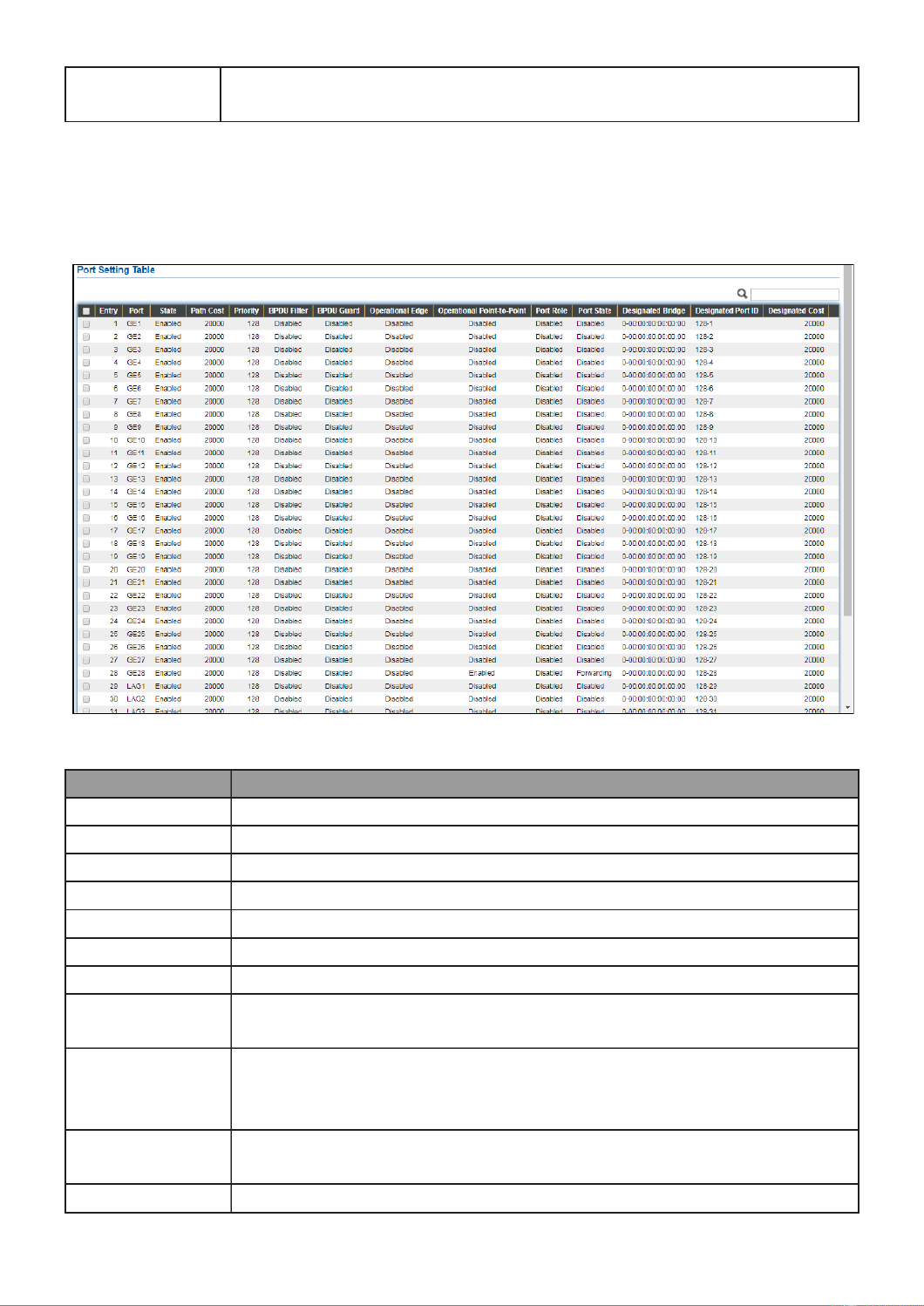
IV-7-2 Port Setting
To configure and display the STP port settings, click . STP > Port Setting
Figure - Spanning Tree > Port Setting 65
Item
Description
Port
Specify the interface ID or the list of interface IDs.
State
The operational state on the specified port.
Path Cost
STP path cost on the specified port.
Priority
STP priority on the specified port.
BPDU Filter
The states of BPDU filter on the specified port.
BPDU Guard
The states of BPDU guard on the specified port.
Operational Edge
The operational edge port status on the specified port.
Operational
Point- -Point to
The operational point- -point status on the specified port. to
Port Role
The current port role on the specified port. The possible values are:
“Disabled”, “Master”, “Root”, “Designated”, “Alternative”, and
“Backup”.
Port State
The current port state on the specified port. The possible values are:
“Disabled”, “Discarding”, “Learning”, and “Forwarding”.
Designated Bridge
The bridge ID of the designated bridge.

71
Designated Port
ID
The designated port ID on the switch.
Designated Cost
The path cost of the designated port on the switch.
Protocol
Migration Check
Restart the Spanning Tree Protocol (STP) migration process
(re-negotiate with its neighborhood) on the specific interface.
Click " " button to view Edit Port Setting menu. Edit
Figure - Spanning Tree > Port Setting > Edit Port Setting 66
Item
Description
Port
Selected port ID.
State
Enable/Disable the STP on the specified port.
Path Cost
Specify the STP path cost on the specified port.
Priority
Specify the STP path cost on the specified port.
Edge Port
Specify the edge mode.
Enable: Force to true state (as link to a host).
Disable: Force to false state (as link to a bridge).

72
In the edge mode, the interface would be put into the
Forwarding state immediately upon link up. If the edge mode is
enabled for the interface and there are BPDUs received on the
interface, the loop might be occurred in the short time before
the STP state change.
BPDU Filter
The BPDU Filter configuration avoids receiving / transmitting
BPDU from the specified ports.
Enable: Enable BPDU filter function.
Disable: Disable BPDU filter function.
BPDU Guard
The BPDU Guard configuration to drop the received BPDU
directly.
Enable: Enable BPDU guard function.
Disable: Disable BPDU guard function.
Point- -Point to
Specify the Point- -Point port configuration: to
Auto: The state is depended on the duplex setting of the port
Enable: Force to true state.
Disable: Force to false state
IV-7-3 MST Instance
To configure MST instance setting, click STP > MST Instance.
Figure - Spanning Tree > MST Instance 67

73
Item
Description
MSTI
Designated port number.
Priority
The bridge priority on the specified MSTI.
Bridge Identifier
The bridge identifier on the specified MSTI.
Designated Root Bridge
The designated root bridge identifier on the specified MSTI.
Root Port
The designated root port on the specified MSTI.
Root Path Cost
The designated root path cost on the specified MSTI.
Remaining Hop
The configuration of remaining hop on the specified MSTI.
VLAN
The VLAN configuration on the specified MSTI.
Click " " button to view Edit MST Instance menu. Edit
Figure - Spanning Tree > MST Instance > Edit MST Instance Setting 68
Item
Description
VLAN
Select the VLAN list for the specified MSTI.
Priority
Specify the bridge priority on the specified MSTI. The valid range
is from 0 to 61440, and the value must be the multiple of 4096. It
ensures the probability that the switch is selected as the root
bridge, and the lower values has the higher priority for the
switch to be selected as the root bridge of the STP topology.

74
IV-7-4 MST Port Setting
To configure and display MST port setting, click STP > MST Port Setting.
Figure - Spanning Tree > MST Port Setting 69
Item
Description
MSTI
Specify the port setting on the specified MSTI.
Port
Specify the interface ID or the list of interface IDs.
Path Cost
The port path cost on the specified MSTI.
Priority
The port priority on the specified MSTI.
Port Role
The current port role on the specified port. The possible values are:
“Disabled”, “Master”, “Root”, “Designated”, “Alternative”, and
“Backup”.
Port State
The current port state on the specified port. The possible values are:
“Disabled”, “Discarding”, “Learning”, and “Forwarding”.
Mode
The operational STP mode on the specified port.
Type
The possible value for the port type are:
Boundary: The port attaching an MST Bridge to a LAN that is not in
the same region.

75
Internal: The port attaching an MST Bridge to a LAN that is not in
the same region.
Designated
Bridge
The bridge ID of the designated bridge.
Designated Port
ID
The designated port ID on the switch.
Designated Cost
The path cost of the designated port on the switch.
Remaining Hop
The remaining hops count on the specified port.
Click " " button to view Edit MST Port Setting menu. Edit
Figure - Spanning Tree > MST Port Setting > Edit MST Port Setting 70
Item
Description
Path Cost
Specify the STP port path cost on the specified MSTI.
Priority
Specify the STP port priority on the specified MSTI.

76
IV-7-5 Stascs
To display the STP stascs, click . STP > Stascs
Figure - Spanning Tree > Stascs 71
Item
Descripon
Refresh Rate
The opon to refresh the stascs automacally.
Receive BPDU (Cong)
The counts of the received CONFIG BPDU.
Receive BPDU (TCN)
The counts of the received TCN BPDU.
Receive BPDU (MSTP)
The counts of the received MSTP BPDU.
Transmit BPDU (Cong)
The counts of the transmied CONFIG BPDU.
Transmit BPDU (TCN)
The counts of the transmied TCN BPDU.
Transmit BPDU (MSTP)
The counts of the transmied MSTP BPDU.
Clear
Clear the stascs for the selected interfaces
View
View the stascs for the interface.

77
Click " " buon to view the STP Port Stasc menu. View
Figure - Spanning Tree > Stascs > STP Port Stasc 72
Item
Descripon
Refresh Rate
The opon to refresh the stascs automacally.
Clear
Clear the stascs for the selected interfaces.

78
IV-8 Discovery
Use this secon to congure LLDP.
IV-8-1 LLDP
LLDP is a one-way protocol; there are no request/response sequences. Informa-on is
adversed by staons implemenng the transmit funcon, and is received and processed
by staons implemenng the receive funcon. The LLDP category contains LLDP and
LLDP-MED pages.
IV-8-1-1 Property
To display LLDP Property Seng web page, click Discovery > LLDP > Property.
Figure - Discovery > LLDP > Property 73
Item
Descripon
State
Enable/ Disable LLDP protocol on this switch.
LLDP Handling
Select LLDP PDU handling acon to be ltered, bridging or ooded
when LLDP is globally disabled.
Filtering: Deletes the packet.
Bridging: (VLAN-aware ooding) Forwards the packet to all VLAN
members.
Flooding: Forwards the packet to all ports
TLV Adverse
Select the interval at which frames are transmied. The default is 30

79
Interval
seconds, and the valid range is 5 32767 seconds. –
Holdme
Mulplier
Select the mulplier on the transmit interval to assign to TTL (range
2 10, default = 4). –
Reinializaon
Delay
Select the delay before a re-inializaon (range 1 10 seconds, default –
= 2).
Transmit Delay
Select the delay aer an LLDP frame is sent (range 1 8191 seconds, –
default = 3).
Fast Start Repeat
Count
Select fast start repeat count when port link up (range 1 10, default = –
3).

80
IV-8-1-2 Port Seng
To display LLDP Port Seng, click Discovery > LLDP > Port Seng.
Figure - Discovery > LLDP > Port Seng 74
Item
Descripon
Port
Port Name.
Mode
The port LLDP mode.
Selectde TLV
The Selected LLDP TLV.

81
Click " " buon to view Edit Port Seng menu. Edit
Figure - Discovery > LLDP > Port Seng > Edit Port Seng 75
Item
Descripon
Port
Select specied port or all ports to congure LLDP state.
Mode
Select the transmission state of LLDP port interface.
Disable: Disable the transmission of LLDP PDUs.
RX Only: Receive LLDP PDUs only.
TX Only: Transmit LLDP PDUs only.
TX And RX: Transmit and receive LLDP PDUs both.
Oponal TLV
Select the LLDP oponal TLVs to be carried (mulple selecon is
allowed).
System Name
Port Descripon
System Descripon
System Capability
802.3 MAC-PHY
802.3 Link Aggregaon
802.3 Maximum Frame Size
Management Address
802.1 PVID.

82
802.1 VLAN
Name
Select the VLAN Name ID to be carried (mulple selecon is
allowed).
IV-8-1-3 Packet View
To display LLDP Overloading, click Discovery > LLDP > Packet View.
Figure - Discovery > LLDP > Packet View 76

83
Item
Descripon
Port
Port Name.
In-Use (Bytes)
Total number of bytes of LLDP informaon in each packet.
Available (Bytes)
Total number of available bytes le for addional LLDP informaon
in each packet.
Operaonal Status
Overloading or not.
Click " " buon to view Packet View Detail menu. Detail
Termékspecifikációk
| Márka: | Edimax |
| Kategória: | kapcsoló |
| Modell: | GS-5416PLC |
Szüksége van segítségre?
Ha segítségre van szüksége Edimax GS-5416PLC, tegyen fel kérdést alább, és más felhasználók válaszolnak Önnek
Útmutatók kapcsoló Edimax

5 Október 2024
27 Szeptember 2024
28 Augusztus 2024
20 Augusztus 2024
4 Augusztus 2024
3 Augusztus 2024
2 Augusztus 2024
1 Augusztus 2024
31 Július 2024
30 Július 2024
Útmutatók kapcsoló
- kapcsoló Yamaha
- kapcsoló Nedis
- kapcsoló Worx
- kapcsoló Philips
- kapcsoló SilverCrest
- kapcsoló Bosch
- kapcsoló Theben
- kapcsoló Panasonic
- kapcsoló Doepke
- kapcsoló StarTech.com
- kapcsoló HP
- kapcsoló Ubiquiti Networks
- kapcsoló SunBriteTV
- kapcsoló TP-Link
- kapcsoló Emos
- kapcsoló Vimar
- kapcsoló LogiLink
- kapcsoló Alcatel
- kapcsoló Digitus
- kapcsoló TRENDnet
- kapcsoló Mercusys
- kapcsoló Boss
- kapcsoló Crestron
- kapcsoló Lancom
- kapcsoló ORNO
- kapcsoló Tripp Lite
- kapcsoló Suevia
- kapcsoló Hikvision
- kapcsoló Vivanco
- kapcsoló Netgear
- kapcsoló Asus
- kapcsoló Jabra
- kapcsoló Hama
- kapcsoló Renkforce
- kapcsoló Iogear
- kapcsoló Mercury
- kapcsoló Mikrotik
- kapcsoló Alpine
- kapcsoló Omnitronic
- kapcsoló Toolcraft
- kapcsoló ZyXEL
- kapcsoló Dahua Technology
- kapcsoló Smart-AVI
- kapcsoló Fibaro
- kapcsoló IPGARD
- kapcsoló Planet
- kapcsoló Ernitec
- kapcsoló Tenda
- kapcsoló Black Box
- kapcsoló Tesla
- kapcsoló Eberle
- kapcsoló Extech
- kapcsoló Gembird
- kapcsoló Cisco
- kapcsoló ATen
- kapcsoló SPC
- kapcsoló Unify
- kapcsoló Behringer
- kapcsoló Nexa
- kapcsoló Powerfix
- kapcsoló BaseTech
- kapcsoló APC
- kapcsoló CyberPower
- kapcsoló Ei Electronics
- kapcsoló Fantini Cosmi
- kapcsoló Electro Harmonix
- kapcsoló PreSonus
- kapcsoló Intertechno
- kapcsoló Manhattan
- kapcsoló Plantronics
- kapcsoló Alecto
- kapcsoló Honeywell
- kapcsoló EnGenius
- kapcsoló Adder
- kapcsoló Velleman
- kapcsoló Grandstream
- kapcsoló D-Link
- kapcsoló Blustream
- kapcsoló Monacor
- kapcsoló Shimano
- kapcsoló Epiphan
- kapcsoló One For All
- kapcsoló Trotec
- kapcsoló Chacon
- kapcsoló Elro
- kapcsoló Delta Dore
- kapcsoló Abus
- kapcsoló GAO
- kapcsoló Tiptel
- kapcsoló Finder
- kapcsoló Konig
- kapcsoló Marmitek
- kapcsoló Pyle
- kapcsoló Emerson
- kapcsoló Kemo
- kapcsoló IFM
- kapcsoló DataVideo
- kapcsoló Atlona
- kapcsoló Schneider
- kapcsoló Lindy
- kapcsoló Cudy
- kapcsoló QNAP
- kapcsoló Vemer
- kapcsoló Kaiser
- kapcsoló Grässlin
- kapcsoló Dormakaba
- kapcsoló Cotech
- kapcsoló Audac
- kapcsoló Siig
- kapcsoló Eaton
- kapcsoló Gefen
- kapcsoló Kathrein
- kapcsoló Homematic IP
- kapcsoló Elation
- kapcsoló Provision-ISR
- kapcsoló Vacmaster
- kapcsoló Brilliant
- kapcsoló Rex
- kapcsoló Equip
- kapcsoló H-Tronic
- kapcsoló Victron Energy
- kapcsoló PCE
- kapcsoló IVT
- kapcsoló Vivolink
- kapcsoló Linksys
- kapcsoló Intelix
- kapcsoló Heitronic
- kapcsoló Alfatron
- kapcsoló Smartwares
- kapcsoló Kopp
- kapcsoló CSL
- kapcsoló Speaka
- kapcsoló Belkin
- kapcsoló RGBlink
- kapcsoló KanexPro
- kapcsoló Kramer
- kapcsoló BZBGear
- kapcsoló Generac
- kapcsoló Ansmann
- kapcsoló Intermatic
- kapcsoló Flamingo
- kapcsoló Brennenstuhl
- kapcsoló Eminent
- kapcsoló KlikaanKlikuit
- kapcsoló Elektrobock
- kapcsoló Sylvania
- kapcsoló Tork
- kapcsoló Techly
- kapcsoló Sonance
- kapcsoló Totolink
- kapcsoló Profile
- kapcsoló Matrox
- kapcsoló Steren
- kapcsoló Perel
- kapcsoló AV:link
- kapcsoló Buffalo
- kapcsoló Audiovox
- kapcsoló LevelOne
- kapcsoló Merten
- kapcsoló Goobay
- kapcsoló Hager
- kapcsoló Sygonix
- kapcsoló Clas Ohlson
- kapcsoló EVE
- kapcsoló UPM
- kapcsoló DoorBird
- kapcsoló Gira
- kapcsoló Jung
- kapcsoló WHALE
- kapcsoló PAC
- kapcsoló Wentronic
- kapcsoló Wago
- kapcsoló Monoprice
- kapcsoló OSD Audio
- kapcsoló Berker
- kapcsoló Aeon Labs
- kapcsoló Advantech
- kapcsoló Merlin Gerin
- kapcsoló Micro Connect
- kapcsoló Extron
- kapcsoló Avocent
- kapcsoló Shelly
- kapcsoló Intellinet
- kapcsoló Ebode
- kapcsoló Robbe
- kapcsoló ICasa
- kapcsoló B-tech
- kapcsoló Legrand
- kapcsoló Kraus & Naimer
- kapcsoló Noble
- kapcsoló Ecler
- kapcsoló Inverto
- kapcsoló Triax
- kapcsoló Rule
- kapcsoló CYP
- kapcsoló Phoenix Contact
- kapcsoló Seuthe
- kapcsoló Maclean Energy
- kapcsoló SmartAVI
- kapcsoló DEHN
- kapcsoló SEC24
- kapcsoló Cooking Performance Group
- kapcsoló Adviti
- kapcsoló Flic
- kapcsoló IB Connect
- kapcsoló Liberty
- kapcsoló PureTools
- kapcsoló Hamlet
- kapcsoló Paladin
- kapcsoló Noark
- kapcsoló Cambium Networks
- kapcsoló 2USB
- kapcsoló Roline
- kapcsoló KVM-TEC
- kapcsoló STI
- kapcsoló Ebara
- kapcsoló Mach Power
- kapcsoló Axing
- kapcsoló ConnectPro
- kapcsoló Atlantis Land
- kapcsoló GEV
- kapcsoló Pizzato Elettrica
- kapcsoló Baco
- kapcsoló SEADA
- kapcsoló Comet
- kapcsoló Setti+
- kapcsoló PureLink
- kapcsoló INOGENI
- kapcsoló Luxul
Legújabb útmutatók kapcsoló
9 Április 2025
9 Április 2025
5 Április 2025
5 Április 2025
5 Április 2025
5 Április 2025
3 Április 2025
3 Április 2025
2 Április 2025
2 Április 2025