Használati útmutató Edimax GS-5216PLC
Olvassa el alább 📖 a magyar nyelvű használati útmutatót Edimax GS-5216PLC (210 oldal) a kapcsoló kategóriában. Ezt az útmutatót 12 ember találta hasznosnak és 2 felhasználó értékelte átlagosan 4.5 csillagra
Oldal 1/210

GS-5424PLC V2/ GS-5216PLC/GS-5210PL
User Manual
08-2021 / v1.1

Contents
I. Product Informaon .............................................................................. 1
I- Package Contents 1. ...................................................................... 2
I- Hardware Overview 2. ................................................................... 2
I- LED Status 3. .................................................................................. 4
II. Geng Started the Conguraon Ulity 6...............................................
III. Web-based Switch Conguraon ........................................................... 8
III- Status 1. ......................................................................................... 8
III-1- System Informaon 81. ............................................................................
III-1- Logging Message 2. ............................................................................... 10
III-1- Port 3. ................................................................................................... 11
III-1-3- Stascs 1. ............................................................................................ 11
III-1-3- Error Disabled 2. ................................................................................... 14
III-1-3- Bandwidth Ulization 3. ........................................................................ 14
III-1- Link Aggregaon 4. ............................................................................... 15
III-1- MAC Address Table 5. ........................................................................... 16
III- Network 2. ................................................................................... 17
III-2- IP Address 1. ......................................................................................... 17
III-2- System Time 2. .....................................................................................19
III- Port 3. .......................................................................................... 22
III-3- Port Seng 1. ....................................................................................... 22
III-3- Long Range Mode 2. ............................................................................. 24
III-3- Error Disable 3. ..................................................................................... 25
III-3- Link Aggregaon 4. ............................................................................... 26
III-3-4- Group 1. ................................................................................................ 26
III-3-4- Port Seng 2. ....................................................................................... 28
III-3-4- LACP 3. .................................................................................................. 30
III-3-4- 4. EEE .................................................................................................... 31
III-3- Jumbo Frame 5. .................................................................................... 32
III- PoE 4. ........................................................................................... 32

III-4- Global Seng 1. ................................................................................... 33
III-4- PoE On/O 2. ........................................................................................ 35
III-4- PD Alive Check 3. .................................................................................. 36
III- VLAN 5. ........................................................................................ 37
III-5- VLAN 1. ................................................................................................. 37
III-5-1- Create VLAN 1. ...................................................................................... 37
III-5-1- VLAN Conguraon 2. ........................................................................... 39
III-5-1- Membership 3. ...................................................................................... 40
III-5-1- Port Seng 4. ....................................................................................... 42
III-5- Voice VLAN 2. ....................................................................................... 43
III-5-2- Property 1. ............................................................................................ 44
III-5-2- Voice OUI 2. .......................................................................................... 45
III-5- MAC VLAN 3. ........................................................................................ 47
III-5-3- MAC Group 1. ....................................................................................... 47
III-5-3- Group Binding 2. ................................................................................... 48
III-5- Surveillance VLAN 4. ............................................................................. 49
III-5-4- Property 1. ............................................................................................ 50
III-5-4- Surveillance OUI 2. ................................................................................ 51
III- MAC Address Table 6. .................................................................. 51
III-6- Dynamic Address 1. .............................................................................. 52
III-6- Stac Address 2. ................................................................................... 52
III-6- Filtering Address 3. ............................................................................... 53
III- Spanning Tree 7. .......................................................................... 53
III-7- Property 1. ............................................................................................ 53
III-7- Port Seng 2. ....................................................................................... 56
III-7- MST Instance 3. .................................................................................... 58
III-7- MST Port Seng 4. ............................................................................... 60
III-7- Stascs 5. ........................................................................................... 62
III- Discovery 8. ................................................................................. 63
III-8- LLDP 1. .................................................................................................. 63
III-8-1- Property 1. ............................................................................................ 64
III-8-1- Port Seng 2. ....................................................................................... 65
III-8-1- Packet View 3. ....................................................................................... 67
III-8-1- Local Informaon 4. .............................................................................. 70
III-8-1- Neighbor 5. ........................................................................................... 72
III-8-1- Stascs 6. ............................................................................................ 76

III- Mulcast 9. .................................................................................. 77
III-9- General 1. ............................................................................................. 77
III-9-1- Property 1. ............................................................................................ 77
III-9-1- Group Address 2. .................................................................................. 78
III-9-1- Router Port 3. ....................................................................................... 80
III-9- IGMP Snooping 2. ................................................................................. 82
III-9-2- Property 1. ............................................................................................ 82
III-9-2- Querier 2. .............................................................................................. 85
III-9-2- Stascs 3. ............................................................................................ 87
III-9- M 3. VR.................................................................................................. 88
III-9-3- Property 1. ............................................................................................ 88
III-9-3- Port Seng 2. ....................................................................................... 89
III-9-3- Group Address 3. .................................................................................. 90
III- Security 10. .................................................................................... 92
III- - RADIUS 10 1. ............................................................................................. 92
III- - Management Access 10 2. ......................................................................... 95
III- -2- Management VLAN 10 1. ........................................................................... 95
III- -2- Management Service 10 2. ........................................................................ 95
III- -2- Management ACL 10 3. .............................................................................. 97
III- -2- Management ACE 10 4. ............................................................................. 98
III- - Authencaon Manager 10 3. ................................................................. 101
III- -3- Property 10 1. .......................................................................................... 101
III- -3- Port Seng 10 2. ..................................................................................... 106
III- -3- Sessions 10 3. .......................................................................................... 109
III- - Port Security 10 4. ................................................................................... 111
III- - Trac Segmentaon 10 5. ....................................................................... 112
III- - Storm Control 10 6. ................................................................................. 114
III- - DoS 10 7. ................................................................................................. 116
III- -7- Property 10 1. .......................................................................................... 116
III- -7- Port Seng 10 2. ..................................................................................... 118
III- - DHCP Snooping 10 8. ............................................................................... 119
III- -8- Property 10 1. .......................................................................................... 120
III- -8- Stascs 10 2. .......................................................................................... 122
III- -8- Opon82 Property 10 3. .......................................................................... 123
III- -8- Opon82 Circuit ID 10 4. .......................................................................... 125
III- - IP Source Guard 10 9. .............................................................................. 126
III- -9- Port Seng 10 1. ..................................................................................... 126
III- -9- IMPV Binding 10 2. ................................................................................... 127
III- -9- Save Database 10 3. ................................................................................. 129

III- ACL 11. ......................................................................................... 130
III- - MAC ACL 11 1. ......................................................................................... 130
III- - MAC ACE 11 2. ......................................................................................... 131
III- - IPv4 ACL 11 3. .......................................................................................... 133
III- - IPv4 ACE 11 4. .......................................................................................... 134
III- - ACL Binding 11 5. ..................................................................................... 137
III- QoS 12. ........................................................................................ 138
III- - General 12 1. ........................................................................................... 138
III- -1- Proper 12 1. ty .......................................................................................... 139
III- -1- Queue Scheduling 12 2. ........................................................................... 141
III- -1- CoS Mapping 12 3. ................................................................................... 142
III- -1- IP Precedence Mapping 12 4. ................................................................... 143
III- - Rate Limit 12 2. ........................................................................................ 144
III- -2- Ingress/Egress Port 12 1. ......................................................................... 144
III ............................................................................- Diagnoscs 13. 145
III- - Logging 13 1. ........................................................................................... 146
III- -1- Property 13 1. .......................................................................................... 146
III- -1- Remote Server 13 2. ................................................................................ 147
III- - Mirroring 13 2. ........................................................................................ 148
III- - Ping 13 3. ................................................................................................. 150
III- - Traceroute 13 4. ...................................................................................... 151
III- - Copper Test 13 5. .................................................................................... 152
III- - Fiber Module 13 6. .................................................................................. 153
III- - UDLD 13 7. ............................................................................................... 154
III- -7- Property 13 1. .......................................................................................... 154
III- -7- Neighbor 13 2. ......................................................................................... 156
III- Management 14. ......................................................................... 157
III- - User Account 14 1. .................................................................................. 157
III- - Fireware 14 2. .......................................................................................... 159
III- -2- Upgrade / Backup 14 1. ........................................................................... 159
III- -2- Acve Image 14 2. ................................................................................... 163
III- - nguraon 14 3. Co .................................................................................. 164
III- -3- Upgrade / Backup 14 1. ........................................................................... 164
III- -3- Save Conguraon 14 2. .......................................................................... 168
III- - SNMP 14 4. .............................................................................................. 168
III- -4- View 14 1. ................................................................................................ 168
III- -4- Group 14 2. .............................................................................................. 169

III- -4- Community 14 3. ..................................................................................... 171
III- -4- User 14 4. ................................................................................................ 173
III- -4- Engine ID 14 5. ......................................................................................... 176
III- -4- Trap Event 14 6. ....................................................................................... 178
III- -4- Nocaon 14 7. ..................................................................................... 178
III- - Time Range 14 5. ..................................................................................... 182
IV. Surveillance Mode .............................................................................. 183
IV ............................................................................- Home Page 1. 183
IV-1- Overview 1. ......................................................................................... 184
IV-1- Port Info 2. .......................................................................................... 185
IV-1- IP Camera Info 3. ................................................................................ 186
IV-1- NVR Info 4. .......................................................................................... 187
IV-1- PoE Info 5. .......................................................................................... 187
IV-1- Status 6. .............................................................................................. 188
IV ......................................................................- PoE Scheduling 2. 189
IV- Time 3. ....................................................................................... 191
IV-3- Clock Sengs 1. .................................................................................. 191
IV-3- SNTP Sengs 2. .................................................................................. 192
IV- Surveillance Sengs 4. .............................................................. 193
IV- Mail Alert 5. ............................................................................... 196
IV- Powered Device Monitor 6. ....................................................... 198
IV ....................................................................................- ONVIF 7. 200
IV-7- IPC Discover 1. .................................................................................... 200
IV-7- NVR Discover 2. .................................................................................. 200
IV- E-map Management 8. .............................................................. 201
IV-8- Image Upload 1. .................................................................................. 201
IV-8- Image Seings 2. ................................................................................ 202
IV-8- E-map View 3. ..................................................................................... 203
IV- Tools 9. ...................................................................................... 203
IV-9- Firmware Informaon 1. ..................................................................... 203
IV-9- Firmware Upgrade & Backup 2. .......................................................... 204

IV-9- Conguraon Restore & Backup 3. ..................................................... 204
IV-9- Reset 4. ............................................................................................... 205
IV-9- Reboot System 5. ................................................................................ 205
V. Cong Reload Buon(Firmware version V1.0.8) .................................. 206
V- ONVIF Compliant Devices Enrollment (Standard Mode) 2081. .......
V- Non-ONVIF Compliant Devices Enrollment (Standard Mode) 2082.
V- ONVIF Compliant Devices Enrollment (Surveillance Mode) 3. ... 210
V- . 2104. Non-ONVIF Compliant Devices Enrollment (Surveillance Mode)

2
I- Package Contents 1.
Before start using this product please check there is anything missing in the , if
package, and contact your dealer to claim the missing item(s):
Model#
Surveillance
VAN
Web-Smart
Switch
Quick
Installao
n Guide
Rack-Mount
Kit
Power
Cord
Console
Cable
GS-5424PLC V2
V
V
V
V
V
GS-5216PLC
V
V
V
V
GS-5210PL
V
V
V
V
I- Hardware Overview 2.
GS-5424PLC V2:
1
2
3
4
5
6
7
8

3
GS-5216PLC:
-5210PL: GS
No.
GS-5424PLC V2
GS-5216PLC
GS-5210PL
1.
Reset Buon
Reset Buon
Reset Buon
2.
LED (PoE/Alert, SYS
PWR)
LED (PoE/Alert, PWR)
LED (PoE/Alert, SYS)
3.
LED PoE
LED PoE
LED Link/Act
4.
LED Link/Act
LED Link/Act
LED PoE
5.
PoE Port 1~24
PoE Port 1~16
PoE Port 1~8
6.
Combo Ports
(RJ45/SFP) 25~28
Combo Ports
(RJ45/SFP) 17~18
RJ45 Port 9~ 10
SFP Port 11~12
7.
Console Port
N/A
N/A
8.
Power Socket
Power Socket
Power Socket
9.
N/A
PWR Consumpon:
PORT, PoE Was
PWR Consumpon:
PORT, PoE Was
10.
Selecon Buon
PWR Consumpon
Status SELECT Buon
PWR Consumpon
Status SELECT Buon
1
2
3
4
5
6
8
9
10
1
2
3
4
5
6
8
9
10
4
I- LED Status 3.
Funcon
Status
Descripon
Data Rate:
10/100/1000M
On ( ) Amber
Port is connected, Link at 10/100M
On ( ) Green
Port is connected, Link at 0 10 0M
O
Port is disconnected or link failure
Flashing
( or ) Amber Green
Sending or receiving data
PoE
On
Feeding power to PoE devices
O
PoE funcon is not active
SFP
On ( ) Green
Port is connected, Link at 1000M
On ( ) Amber
Port is connected, Link at 100M
Flashing
( or ) Amber Green
Sending or receiving data
PoE/Alert
On
Total PoE power consumed is
exceeding PoE power budget
O
Total PoE power consumed is under
PoE power budget
SYS PWR
On ( ) Green
System Power on
O
System Power o
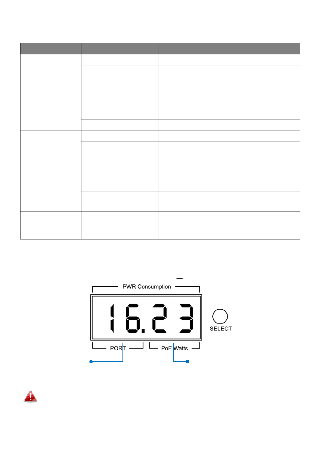
7-Segment LED Power Consumpon Status
(GS-5216PLC & GS-5210PL ONLY)
Note: e LED indicator shows you the status of Total PoE Power Budget or Th “ ”
“PoE Power Budget Le when only 3 LED indicators are lighted on ”
Port #
PoE Power Consumpon
(Was) of the Port

5
NOTE:
Please press Selecon Buon change the power LED status the “ ” to
indicator.
- Without pressing the selecon buon:
The LED status indicator shows the total power budget.
- Press the selecon buon twice:
The LED status indicator shows the total power budget le.
If you want to see power consumpon of each port, each me the buon is
pressed the power consumpon is displayed as follows. ,

6
II. Geng Started the Conguraon Ulity
This secon describes how to navigate the web-based switch conguraon
ulity. Be sure to disable any pop-up blocker.
Launching the Conguraon Ulity:
To open the web-based conguraon utility:
1. Open a Web browser.
2. Enter the IP address of the device you are conguring in the address bar on
the browser (factory default IP address is ) and then press 192.168.2.1
Enter.
3. The default username is and the default password is . admin 1234

7
4. The rst me that you log in with the default username and password,
you are required to enter a New Password and Conrm Password
5. For more informaon about Web-based Conguraon Ulity, please
download User Manual from EDIMAX Download Center:
hps://www.edimax.com/download
NOTE: must be in the same subnet as Your computer’s IP address
the switch. For example, if the switch is using the factory default
IP address, your computer’s IP address can be in the following
range: 192.168.2.x (whereas x is a number from 2 to 254).
Aer a successful connecon, the login window displays.
8
III. Web-based Switch Conguraon
The Surveillance VLAN PoE+ Web Smart switches provide rich funconalies. This chapter
describes how to use the web-based management interface (Web UI) to congure the
switch’s features.
For the purposes of this manual -5424PLC V2/GS-5216PLC/GS-5210PL, the user of GS
interface is separated into ve secons, as shown in the following gure:
III 1.- Status
Use the Status pages to view system informaon and status.
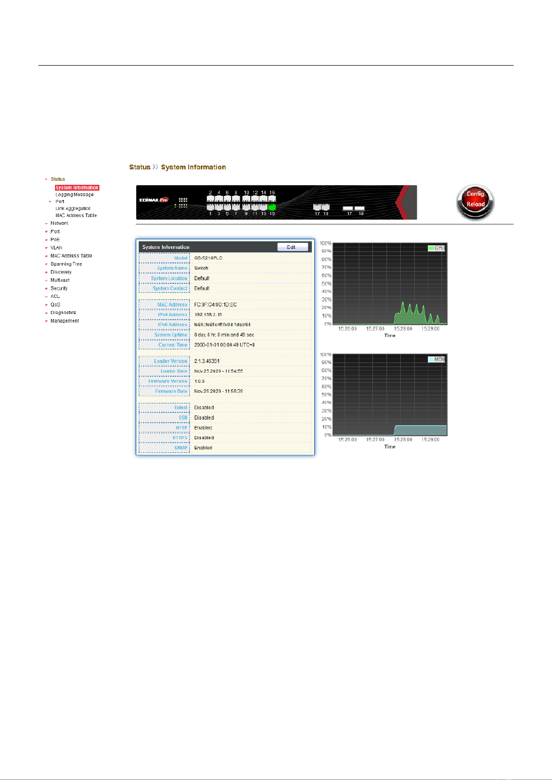
III 1.-1- System Informaon
This page shows switch panel, CPU ulizaon, Memory ulization and other system
current informaon. It also allows user to edit some system informaon.
To display the Device Informaon web page, click Status > System Informaon.

9
Figure 12 - Status > System Informaon
Item
Descripon
Model
Model name of the switch.
System Name
System name of the switch. This name will also use as CLI
prex of each line. (“Switch>” or “Switch#”).
System Locaon
Locaon informaon of the switch.
System Contact
Contact informaon of the switch.
MAC Address
Base MAC address of the switch.
IPv4 Address
Current system IPv4 address.
IPv6 Address
Current system IPv6 address.
System Upme
Total elapsed me from boong.
Current Time
Current system me.
Loader Version
Boot loader image version.
Loader Date
Boot loader image build date.
Firmware Version
Current running rmware image version.
Firmware Date
Current running rmware image build date.
Telnet
Current Telnet service enable/disable state.
SSH
Current SSH service enable/disable state.
HTTP
Current HTTP service enable/disable state.
HTTPS
Current HTTPS service enable/disable state.
SNMP
Current SNMP service enable/disable state.
10
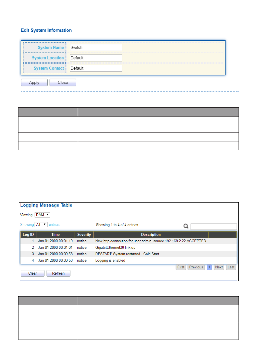
Click “Edit” buon on the table tle to edit following system informaon.
Figure 13 - Status > System Informaon > Edit System Informaon
Item
Descripon
System Name
System name of the switch. This name will also use as CLI
prex of each line. (“Switch>” or “Switch#”).
System Locaon
Locaon informaon of the switch.
System Contact
Contact informaon of the switch.
III 2.-1- Logging Message
To view the logging messages stored on the RAM and Flash, click Status > Logging
Message.
Figure 14 - Status > Logging Message
Item
Descripon
Log ID
The log idener.
Time
The me stamp for the logging message.
Severity
The severity for the logging message.
Descripon
The description of logging message.

11
Viewing
RAM: Show the logging messages stored on the RAM.
Flash: Show the logging messages stored on the Flash.
Clear
Clear the logging messages.
Refresh
Refresh the logging messages.
III 3.-1- Port
III 1.-1-3- Stascs
This page displays standard counters on network trac form the Interfaces, Ethernet
-like and RMONMIB. Interfaces and Ethernet-like counters display errors on the trac
passing through each port. RMON counters provide a total count of dierent frame types
and sizes passing through each port. The “Clear” buon will clear MIB counter of current
selected port.
To display the Port Flow Chart web page, click Status > Port > Stascs.
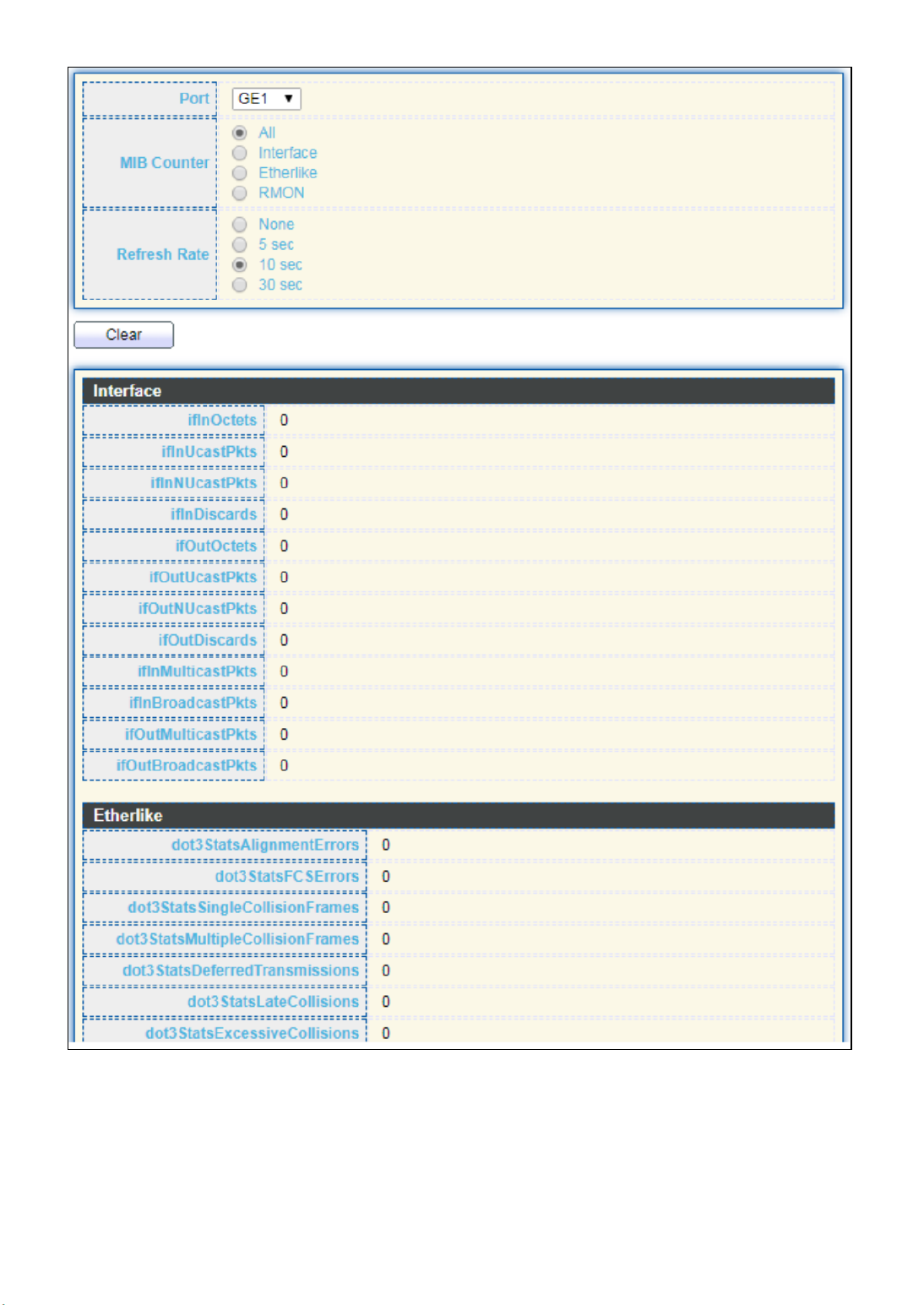
12

13
Figure 15 - Status > Port > Stascs
Item
Descripon
Port
Select one port to show counter statiscs.
MIB Counter
Select the MIB counter to show dierent counter type
All: All counters.
Interface: Interface related MIB counters.
Etherlike: Ethernet-like related MIB counters.
RMON: RMON related MIB counters.
Refresh Rate
Refresh the web page every period of seconds to get new
counter of specied port.

14
III 2.-1-3- Error Disabled
To display the Error Disabled web page, click Status > Port > Error Disabled.
Figure 16 - Status > Port > Error Disabled
Item
Description
□
Select one or more port to operate.
Port
Interface or port number.
Reason
Port will be disabled by one of the following error reason:
BPDU Guard
UDLD
Self Loop
Broadcast Flood
Unknown Mulcast Flood
Unicast Flood
ACL
Port Security Violaon
DHCP rate limit
ARP rate limit
Time Le (sec)
The me le in second for the error recovery.
Refresh
Refresh the current page.
Recover
Recover the selected port status.
III 3.-1-3- Bandwidth Utilization
This page allow user to browse ports’ bandwidth ulizaon in real me. This page will
refresh automacally in every refresh period.

15
To display Bandwidth Ulizaon web page, click Status > Port > Bandwidth Ulizaon.
Figure 17 - Status > Port > Bandwidth Ulizaon
Item
Descripon
Refresh Rate
Refresh the web page every period of seconds to get new
bandwidth ulizaon data.
III 4.-1- Link Aggregaon
To display the Link Aggregaon web page, click Status > Link Aggregaon.
Figure 18 - Status > Link Aggregaon
16
Item Descripon
LAG
LAG Name.
Name
LAG port description.
Type
The type of the LAG.
Stac: The group of ports assigned to a stac LAG are
always acve members.
LACP: The group of ports assigned to dynamic LAG are
candidate ports. LACP determines which candidate ports
are acve member ports.
Link Status
LAG port link status.
Acve Member
Acve member ports of the LAG.
Inacve Member
Inacve member ports of the LAG.
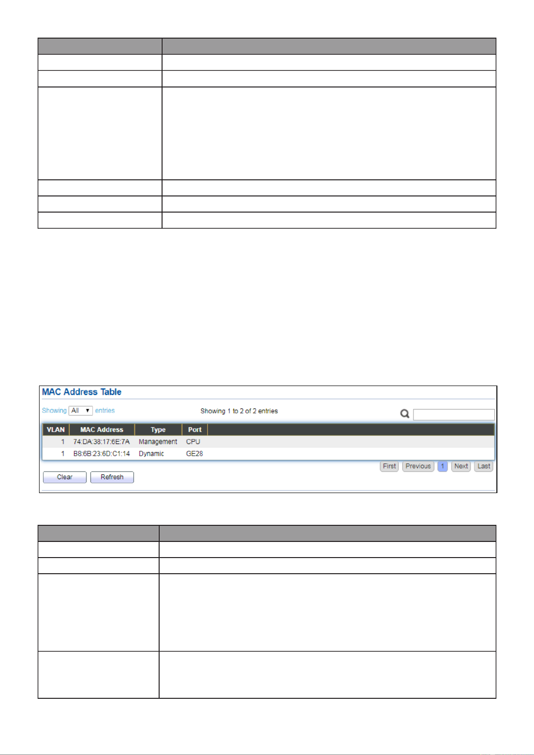
III 5.-1- MAC Address Table
The MAC address table page displays all MAC address entries on the switch including
stac MAC address created by administrator or auto learned from hardware. The “Clear”
buon will clear all dynamic entries and “Refresh” buon will retrieve latest MAC
address entries and show them on page.
To display the MAC Address Table web page, click Status > MAC Address Table.
Figure 19 - Status > MAC Address Table
Item
Descripon
VLAN
VLAN ID of the mac address.
MAC Address
MAC address.
Type
The type of MAC address
Management: DUT’s base mac address for management
Purpose.
Stac: Manually congured by administrator
Dynamic: Auto learned by hardware.
Port
The type of Port
CPU: DUT’s CPU port for management purpose.
Other: Normal switch port.

17
III 2.- Network
Use the Network pages to congure sengs for the switch network interface and how
the switch connects to a remote server to get services.
III 1.-2- IP Address
This secon allows you to edit the IP address, Netmask, Gateway and DNS server of the
switch.
To view the IP Address menu, navigate to Network > IP Address.

18
Figure 20 - Network > IP Address

19
Item
Descripon
Address Type
The address type of switch IP conguraon including
Stac: Stac IP congured by users will be used.
Dynamic: Enable the DHCP to obtain the IP address from a
DHCP server.
IP Address
Specify the switch stac IP address on the stac
conguraon.
Subnet Mask
Specify the switch subnet mask on the stac conguraon.
Default Gateway
Specify the default gateway on the stac conguraon. The
default gateway must be in the same subnet with switch IP
address conguraon.
DNS Server 1
Specify the primary user-dened IPv4 DNS server
conguraon.
DNS Server 2
Specify the secondary user-dened IPv4 DNS server
conguraon.
Table 3-2: IPv6 Address elds
IPv4 Address
The operaonal IPv4 address of the switch.
IPv4 Gateway
The operaonal IPv4 gateway of the switch.
IPv6 Address v6
The operaonal IPv6 address of the switch.
IPv6 Gateway
The operaonal IPv6 gateway of the switch.
Link Local Address
The IPv6 link local address for the switch.
III 2.-2- System Time
This page allow user to set me source, stac me, me zone and daylight saving
sengs. Time zone and daylight saving takes eect both stac me or me from SNTP
server.
To display System Time page, click Network > System Time.

20
Figure 21 - Network > System Time

21
Item Descripon
Source
Select the me source.
SNTP: Time sync from NTP server.
From Computer: Time set from browser host.
Manual Time: Time set by manually congure.
Time Zone
Select a me zone dierence from lisng district.
SNTP
Address Type
Select the address type of NTP server. This is enabled when
me source is SNTP.
Server Address
Input IPv4 address or hostname for NTP server. This is enabled
when me source is SNTP.
Server Port
Input NTP port for NTP server. Default is 123. This is enabled
when me source is SNTP.
Manual Time
Date
Input manual date. This is enabled when me source is manual.
Time
Input manual me. This is enabled when me source is manual.
Daylight Saving Time
Type
Select the mode of daylight saving me.
Disable: Disable daylight saving me.
Recurring: Using recurring mode of daylight saving me.
Non-Recurring: Using non-recurring mode of daylight saving
me.
USA: Using daylight saving me in the United States that
starts on the second Sunday of March and ends on the rst
Sunday of November.
European: Using daylight saving me in the Europe that
starts on the last Sunday in March and ending on the last
Sunday in October.
Oset
Specify the adjust oset of daylight saving me.
Recurring From
Specify the starng me of recurring daylight saving me. This
eld available when selecng “Recurring” mode.
Recurring To
Specify the ending me of recurring daylight saving me. This
eld available when selecng “Recurring” mode.
Non-recurring
From
Specify the starng me of non-recurring daylight saving me.
This eld available when selecng “Non Recurring” mode.-
Non-recurring
To
Specify the ending me of recurring daylight saving me. This
eld available when selecng “Non Recurring” mode.-
Non-recurring
From
Specify the starng me of non-recurring daylight saving me.
This eld available when selecng “Non Recurring” mode.-
Non recurring
To
Specify the ending me of recurring daylight saving me. This
eld available when selecng “Non Recurring” mode.-

22
III 3.- Port
Use the Port pages to congure sengs for switch port related features.
III 1.-3- Port Seng
This page shows port current status and allow user to edit port congura-ons. Select
port entry and click “ ” buon to edit port conguraons.Edit
To display Port Seing web page, click . Port > Port Seng
Figure 22 - Port > Port Seing
Item
Descripon
Port
Port Name.
Type
Port media type.
Descripon
Port Descripon.
State
Port admin state
Enabled: Enable the port.
Disabled: Disable the port.
Link Status
Current port link status
Up: Port is link up.
Down: Port is link down.
Speed
Current port speed conguraon and link speed status.
Duplex
Current port duplex conguraon and link duplex status.
Flow Control
Current port ow control conguraon and link ow control
status.

23
Click “ ” buon to edit Port Seng menuEdit
Figure 23 - Port > Port Seng > Port Seng
Item
Descripon
Port
Selected Port list.
Descripon
Port media type.
State
Port admin state.
Enabled: Enable the port.
Disabled: Disable the port.
Speed
Port speed capabilies.
Auto: Auto speed with all capabilies.
Auto-10M: Auto speed with 10M ability only.
Auto-100M: Auto speed with 100M ability only.
Auto-1000M: Auto speed with 1000M ability only.
Auto-10M/100M: Auto speed with 10M/100M abilies.
10M: Force speed with 10M ability.
100M: Force speed with 100M ability.
1000M: Force speed with 1000M ability.
Duplex
Port duplex capabilies.
Auto: Auto duplex with all capabilies.
Half: Auto speed with 10M and 100M ability only.
Full: Auto speed with 10M/100M/1000M ability only.
Flow Control
Port ow control.

24
Auto: Auto ow control by negoaon.
Enabled: Enable ow control ability.
Disabled: Disable ow control ability.
III 2.-3- Long Range Mode
This page shows port current status and Enable long range mode will double the cabling
distance but reduce the speed to 10Mbps.
To display Long Range Mode web page, click Port > Long Range Mode Seng.
Figure 24 - Port > Long Range Mode

25
III 3.-3- Error Disable
To display Error Disabled web page, click Port > Error Disabled
Figure 25 - Port > Error disable
Item
Descripon
Recover
Interval
Auto recovery aer this interval for error disabled port.
BPDU Guard
Enabled to auto shutdown port when BPDU Guard reason occur.
This reason caused by STP BPDU Guard mechanism.
UDLD
Enabled to auto shutdown port when UDLD violaon occur.
Self Loop
Enabled to auto shutdown port when Self Loop reason occur.
Broadcast
Flood
Enabled to auto shutdown port when Broadcast Flood reason
occur. This reason caused by broadcast rate exceed broadcast
storm control rate.
Unknown
Mulcast Flood
Enabled to auto shutdown port when Unknown Mulcast Flood
reason occur. This reason caused by unknown mulcast rate
exceed unknown mulcast storm control rate.
Unicast Flood
Enabled to auto shutdown port when Unicast Flood reason
occur. This reason caused by unicast rate exceed unicast storm
control rate.
ACL
Enabled to auto shutdown port when ACL shutdown port reason
occur. This reason caused packet match the ACL shutdown port
acon.
Port Security
Enabled to auto shutdown port when Port Security Violaon

26
reason occur. This reason caused by violaon port security rules.
DHCP rate limit
Enabled to auto shutdown port when DHCP rate limit reason
occur. This reason caused by DHCP packet rate exceed DHCP rate
limit.
ARP rate limit
Enabled to auto shutdown port when ARP rate limit reason
occur. This reason caused by DHCP packet rate exceed ARP rate
limit.
III 4.-3- Link Aggregaon
III 1.-3-4- Group
This page allow user to congure link aggregaon group load balance algorithm and
group member.
To view the Group menu, navigate to Port > Link Aggregaon > Group.
Figure 26 - Port > Link Aggregaon > Group
Item
Descripon
Load Balance
Algorithm
LAG load balance distribuon algorithm
src-dst-mac: Based on MAC address.
src-dst-mac-ip: Based on MAC address and IP address.
LAG
LAG Name.
Name
LAG port description.

27
Type
The type of the LAG
Stac: The group of ports assigned to a stac LAG are
always acve members.
LACP: The group of ports assigned to dynamic LAG are
candidate ports. LACP determines which candidate ports
are acve member ports.
Link Status
LAG port link status
Acve Member
Acve member ports of the LAG.
Inacve Member
Inacve member ports of the LAG.
Click “ ” to edit Link Aggregaon Group menu.Edit
Figure 27 - Port > Link Aggregaon > Group > Edit Link Aggregaon Group
Item
Descripon
LAG
Selected LAG group ID.
Name
LAG port description.
Type
The type of the LAG
Stac: The group of ports assigned to a stac LAG are
always acve members.
LACP: The group of ports assigned to dynamic LAG are
candidate ports. LACP determines which candidate ports
are acve member ports.
Member
Select available port to be LAG group member port.

28
III 2.-3-4- Port Seng
This page shows LAG port current status and allow user to edit LAG port conguraons.
Select LAG entry and click “ ” buon to edit LAG port conguraons.Edit
To display LAG Port Seng web page, click Port > Link Aggregaon > Port Setng.
Figure 28 - Port > Link Aggregaon > Port Seng
Item
Descripon
LAG
LAG Port Name.
Type
LAG Port media type.
Descripon
LAG Port description.
State
LAG Port admin state
Enabled: Enable the port.
Disabled: Disable the port.
Link Status
Current LAG port link status
Up: Port is link up.
Down: Port is link down.
Speed
Current LAG port speed conguraon and link speed status.
Duplex
Current LAG port duplex conguraon and link duplex
status.
Flow Control
Current LAG port ow control conguraon and link ow
control status.
29
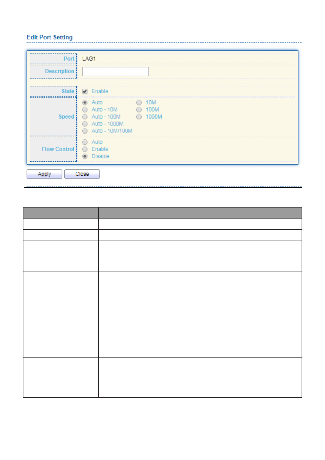
Click “ ” to view Edit Port Setting menu.Edit
Figure 29 - Port > Link Aggregation > Port Setting > Edit Port Setting
Item
Description
Port
Selected Port list.
Description
Port description.
State
Port admin state
Enabled: Enable the port.
Disabled: Disable the port.
Speed
Port speed capabilities
Auto: Auto speed with all capabilities.
Auto-10M: Auto speed with 10M ability only.
Auto-100M: Auto speed with 100M ability only.
Auto-1000M: Auto speed with 1000M ability only.
Auto-10M/100M: Auto speed with 10M/100M abilities.
10M: Force speed with 10M ability.
100M: Force speed with 100M ability.
1000M: Force speed with 1000M ability.
Flow Control
Port flow control
Auto: Auto flow control by negotiation.
Enabled: Enable flow control ability.
Disabled: Disable flow control ability.

30
III 3.-3-4- LACP
This page allow user to configure LACP global and port configurations. Select ports and
click “ ” button to edit port configuration.Edit
To display the LACP Setting web page , click Port > Link Aggregation > LACP.
Figure 30 - Port > Link Aggregation > LACP
Item
Description
System Priority
Configure the system priority of LACP. This decides the
system priority field in LACP PDU.
Port
Port Name.
Port Priority
LACP priority value of the port.
Timeout
The periodic transmissions type of LACP PDUs.
Long: Transmit LACP PDU with slow periodic (30s).
Short: Transmit LACPP DU with fast periodic (1s).
Click " " button to view Edit LACP Port Setting menu. Edit
Figure 31 - Port > Link Aggregation > LACP > Edit LACP Port Setting

31
Item
Description
Port
Selected port list.
Port Priority
Enter the LACP priority value of the port
Timeout
The periodic transmissions type of LACP PDUs.
Long: Transmit LACP PDU with slow periodic (30s).
Short: Transmit LACPP DU with fast periodic (1s).
III 4.-3-4- EEE
This page allow user to configure Energy Efficient Ethernet settings.
To display the EEE web page, click . Port > EEE
Figure 32 - Port > EEE
Item
Description
Port
Port Name.
State
Port EEE admin state
Enabled: EEE is enabled.
Disabled: EEE is disabled.
Operational Status
Port EEE operational status
Enabled: EEE is operating.
Disabled: EEE is no operating.
Click “ ” to edit the EEE menu.Edit
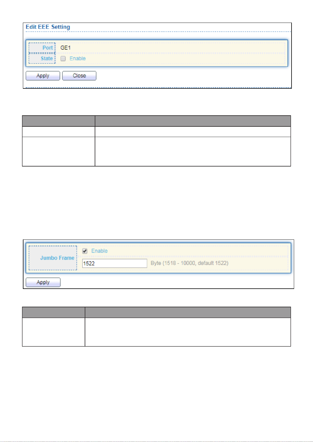
32
Figure 33 - Port > EEE > Edit EEE Setting
Item
Description
Port
Port Name
State
Port EEE admin state
Enabled: EEE is enabled.
Disabled: EEE is disabled.
III 5.-3- Jumbo Frame
This page allow user to configure switch jumbo frame size.
To display Jumbo Frame web page, click Port > Jumbo Frame.
Figure 34 - Port > Jumbo Frame
Item
Description
Jumbo Frame
Enable or disable jumbo frame. When jumbo frame is enabled,
switch max frame size is allowed to configure. When jumbo
frame is disabled, default frame size 1522 will be used.
III 4.- PoE
Port security can set port isolation and specific behavior.

33
III 1.-4- Global Setting
To display the Global web page, click PoE > Global Setting.
Figure 35 - PoE > Global Setting

34
Item
Description
Nominal Power
Maximum supply power.
Consuming Power
Current consumed power.
Remaining Power
Remaining available power.
Schedule Status
Schedule status global switch.
Name
PoE Schedule Name.
Port List
The ports provide power in designated schedule index.
Schedule Status
The current schedule status.
Click “ ” to view PoE Schedule List menu.Edit
Figure 36 - PoE > Priority Setting > Edit PoE Schedule Edit
Item
Description
Index
The serial number of schedule list.
Schedule Status
Schedule Status
Checked: Schedule status is enabled.
Unchecked: Schedule status is disabled.
Name
Enter the PoE schedule name.
Date
Select a valid time for this schedule.
Port List
Select the port provide power.

35
III 2.-4- PoE On/Off
To display the PoE Status web page, click PoE > Power On/Off.
Figure 40 - PoE > Power On/off
Per Port PoE Status
Checked: Port PoE status is enabled.
Unchecked: Port PoE status is disabled.

36
III 3.-4- PD Alive Check
This page shows the information of each ports, including mode, ping PD IP Address,
interval time, retry count, action, reboot time and connect status.
To display port setting page, please click the Edit button. “ ”

37
Item
Description
Port list
Display the interface of port entry.
Status
Enable/Disable
Ping PD IP Address
Input IP address of the PD
Internal Time
The default setting about Interval (30 seconds) will
make switch detect the PD status by performing ping
requests every 30 seconds.
Retry Count
If there is no ping reply from the PD, retry count
starts to count from 1. Once retry count is reached to
2 times, the switch will perform the action in which
you defined.
Action
The Action including none, PD reboot, Reboot &
Alarm and Alarm
Reboot Time
Set the switch reboot time
III 5.- VLAN
A virtual local area network, virtual LAN or VLAN, is a group of hosts with a common set
of requirements that communicate as if they were attached to the same broadcast
domain, regardless of their physical location. A VLAN has the same attributes as a
physical local area network (LAN), but it allows for end stations to be grouped togeth-er
even if they are not located on the same network switch. VLAN membership can be
configured through software instead of physically relocating devices or connections.
III 1.-5- VLAN
Use the VLAN pages to configure settings of VLAN.
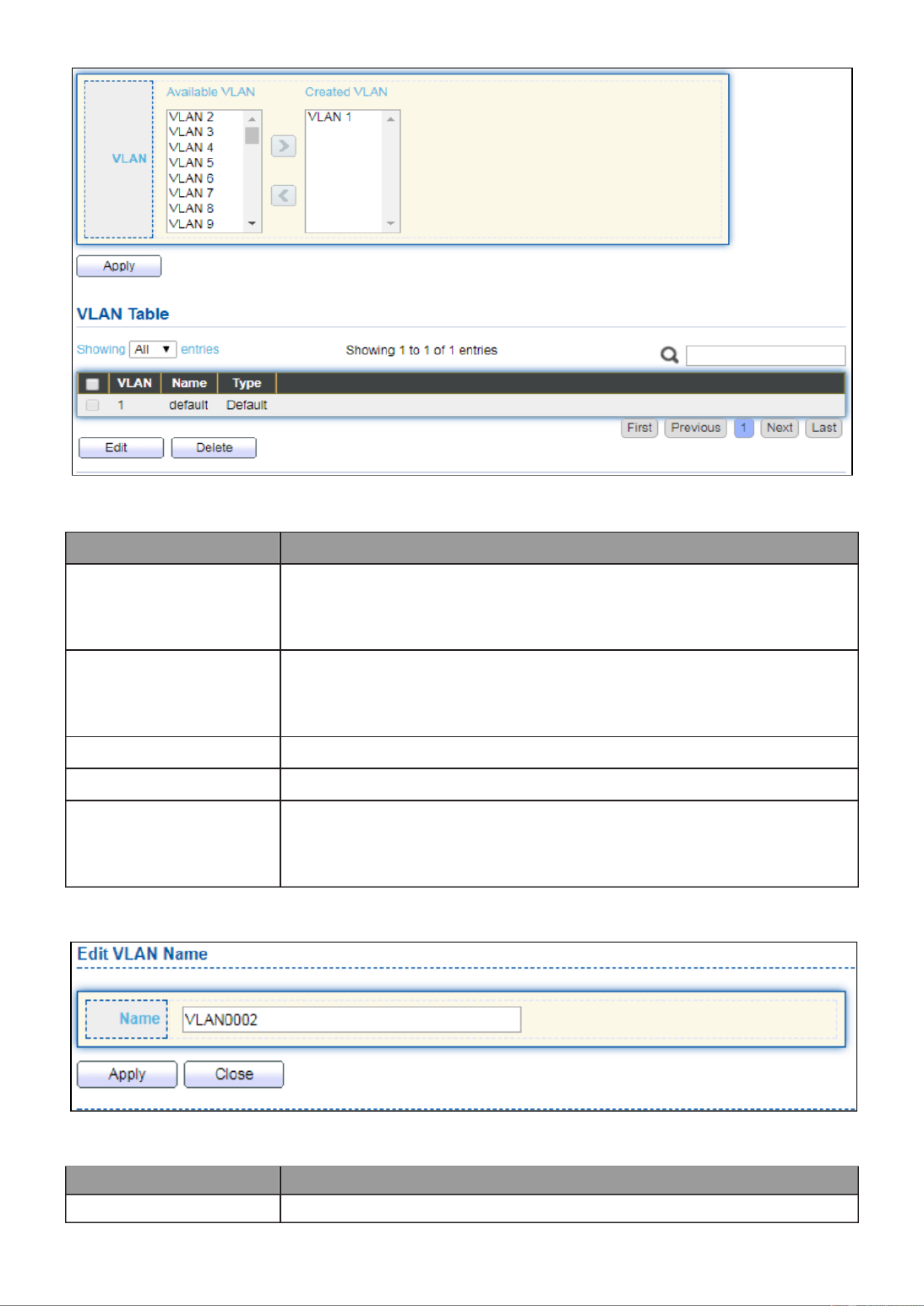
III 1.-5-1- Create VLAN
This page allows user to add or delete VLAN ID entries and browser all VLAN entries that
add statically or dynamic learned by GVRP. Each VLAN entry has a unique name, user can
edit VLAN name in edit page.
To display Create VLAN page, click VLAN > VLAN > Create VLAN.
38
Figure 41 - VLAN > VLAN > Create VLAN
Item
Description
Available VLAN
VLAN has not created yet.
Select available VLANs from left box then move to right box
to add.
Created VLAN
VLAN had been created.
Select created VLANs from right box then move to left box to
delete
VLAN
The VLAN ID.
Name
The VLAN Name.
Type
The VLAN Type.
Static: Port base VLAN.
Dynamic: 802.1q VLAN.
Click “ ” button to view Edit VLAN Name menu.Edit
Figure 42 - VLAN > VLAN > Create VLAN > Edit VLAN Name
Item
Description
Name
Input VLAN name.

39
III 2.-5-1- VLAN Configuration
This page allow user to configure the membership for each port of selected VLAN.
To display VLAN Configuration page, click VLAN > VLAN > VLAN Configuration.
Figure 43 - VLAN > VLAN > VLAN Configuration
Item
Description
VLAN
Select specified VLAN ID to configure VLAN configuration.
Port
Display the interface of port entry.
Mode
Display the interface VLAN mode of port.
Membership
Select the membership for this port of the specified VLAN ID.
Forbidden: Specify the port is forbidden in the VLAN.
Excluded: Specify the port is excluded in the VLAN.
Tagged: Specify the port is tagged member in the VLAN.
Untagged: Specify the port is untagged member in the
VLAN.
PVID
Display if it is PVID of interface.
41
Figure 45 - VLAN > VLAN > Membership > Edit Port Setting
Item
Description
Port
Display the interface.
Mode
Display the VLAN mode of interface.
Membership
Select VLANs of left box and select one of following membership
then move to right box to add membership. Select VLANs of right
box then move to left box to remove membership. Tagging
membership may not choose in differ VLAN port mode. Select the
time source.
Forbidden: Set VLAN as forbidden VLAN.
Excluded: This option is always disabled.
Tagged: Set VLAN as tagged VLAN.
Untagged: Set VLAN as untagged VLAN.
PVID: Check this checkbox to select the VLAN ID to be the
port-based VLAN ID for this port. PVID may auto select or can’t
select in differ settings.

42
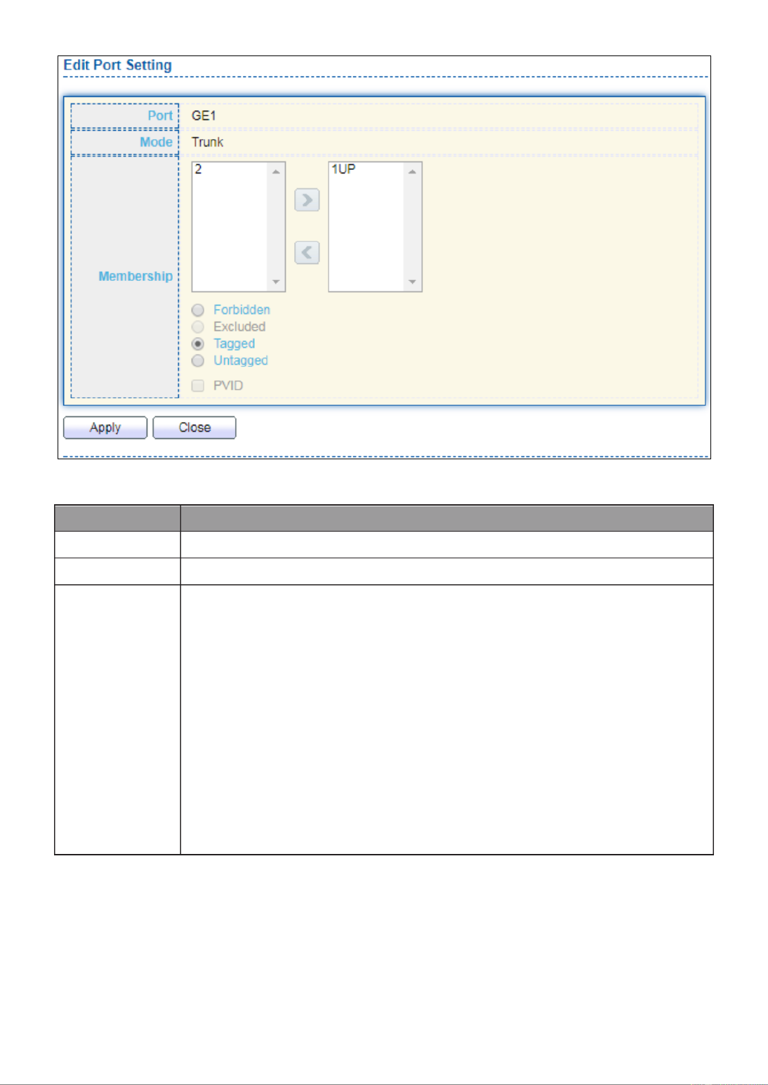
III 4.-5-1- Port Setting
This page allow user to configure ports VLAN settings such as VLAN port mode, PVID
etc…The attributes depend on different VLAN port mode.
To display Port Setting page, click . VLAN > VLAN > Port Setting
Figure 46 - VLAN > VLAN > Port Setting
Item
Description
Port
Display the interface.
Mode
Display the VLAN mode of interface.
PVID
Display the Port-based VLAN ID of port.
Accept Frame Type
Display accept frame type of port.
Ingress Filtering
Display ingress filter status of port.
Uplink
Display uplink status.
TPID
Display TPID used of interface.
Click “Edit” button to Edit Port Setting menu.

43
Figure 47 - VLAN > VLAN > Port Setting > Edit Port Setting
Item
Description
Port
Display selected port to be edited.
Mode
Select the VLAN mode of the interface.
Forbidden: Set VLAN as forbidden VLAN.
Hybrid: Support all functions as defined in IEEE 802.1Q
specification.
Access: Accepts only untagged frames and join an untagged
VLAN.
Trunk: An untagged member of one VLAN at most, and is a
tagged member of zero or more VLANs.
PVID
Specify the port-based VLAN ID (1-4094). It’s only available with
Hybrid and Trunk mode.
Accepted
Type
Specify the acceptable-frame-type of the specified interfaces. It’s
only available with Hybrid mode.
Ingress
Filtering
Set checkbox to enable/disable ingress filtering. It’s only available
with Hybrid mode.
Uplink
Set checkbox to enable/disable uplink mode. It’s only available with
trunk mode.
TPID
Select TPID used of interface. It’s only available with trunk mode.
III 2.-5- Voice VLAN
Use the Voice VLAN pages to configure settings of Voice VLAN.

44
III 1.-5-2- Property
This page allow user to configure global and per interface settings of voice VLAN.
To display Property Web page, click VLAN> Voice VLAN> Property.
Figure 48 - VLAN > Voice VLAN > Property
Item
Description
State
Set checkbox to enable or disable voice VLAN function.
VLAN
Select Voice VLAN ID. Voice VLAN ID cannot be default VLAN.
Cos/802.1p
Select a value of VPT. Qualified packets will use this VPT value as
inner priority.
Remarking
Set checkbox to enable or disable 1p remarking. If enabled, qualified
packets will be remark by this value.
Aging Time
Input value of aging time. Default is 1440 minutes. A voice VLAN
entry will be age out after this time if without any packet pass
through.
Port Setting Table
Port
Display port entry.
State
Display enable/disabled status of interface.
Mode
Display voice VLAN mode.
QoS Policy
Display voice VLAN remark will effect which kind of packet.
Click “ ” button to view Edit Port Setting menu.Edit

45
Figure 49 - VLAN > Voice VLAN > Property > Edit Port Setting
Item
Description
Port
Display selected port to be edited.
State
Set checkbox to enable/disabled voice VLAN function of interface.
Mode
Select port voice VLAN mode
Auto: Voice VLAN auto detect packets that match OUI table and
add received port into voice VLAN ID tagged member.
Manual: User need add interface to VLAN ID tagged member
manually.
QoS Policy
Select port QoS Policy mode
Voice Packet: QoS attributes are applied to packets with OUIs in
the source MAC address.
All: QoS attributes are applied to packets that are classified to
Voice VLAN.
III 2.-5-2- Voice OUI
This page allow user to add, edit or delete OUI MAC addresses. Default has 8 pre-defined
OUI MAC.
To display the Voice OUI Web page, click VLAN > Voice VLAN > Voice OUI.

46
Figure 50 - VLAN > Voice VLAN > Voice OUI
Item
Description
OUI
Display OUI MAC address.
Description
Display description of OUI entry.
Click “Add” or “Edit” button to Add/Edit Voice OUI menu.
Figure 51 - VLAN > Voice VLAN > Voice OUI > Add/Edit Voice OUI
Item
Description
OUI
Input OUI MAC address. Can’t be edited in edit dialog.
Description
Input description of the specified MAC address to the voice
VLAN OUI table.

47
III 3.-5- MAC VLAN
Use the MAC VLAN pages to configure settings of MAC VLAN.
III 1.-5-3- MAC Group
This page allow user to add or edit groups settings of MAC VLAN.
To display the MAC page , click VLAN > MAC VLAN > MAC Group.
Figure 52 - VLAN > MAC VLAN > MAC Group
Item
Description
Group ID
Display group ID of entry.
MAC Address
Display mac address of entry.
Mask
Display mask of mac address for classified packet.
Click “ ” button or "Add Edit" button to view Add/Edit MAC menu.

48
Figure 53 - VLAN > MAC VLAN > MAC Group > Add/Edit MAC
Item
Description
Group ID
Input group ID that is a unique ID of mac group entry. The
range from 1 to 2147483647. Only available on Add Dialog.
MAC Address
Input mac address for classifying packets.
Mask
Input mask of mac address.
III 2.-5-3- Group Binding
This page allow user to bind MAC VLAN group to each port with VLAN ID.
To display Group Binding page, click VLAN> MAC VLAN > Group Binding.
Figure 54 - VLAN > MAC VLAN > Group Binding
Item
Description
Port
Display port ID that binding with MAC group entry.
Group ID
Display group ID that port binding with.
VLAN
Display VLAN ID that assign to packets which match MAC
group.
Click “ ” or “Add Edit” button to view the Add/Edit Group Binding menu.
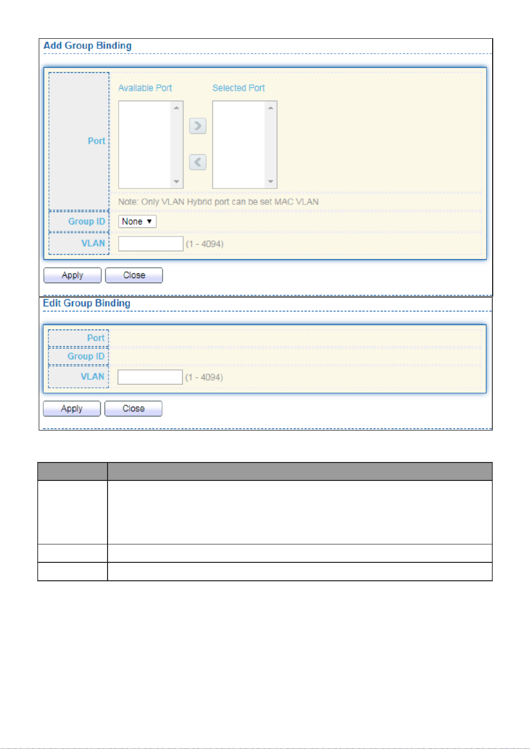
49
Figure 55 - VLAN > MAC VLAN > Add/Edit Group Binding
Item
Description
Port
Select ports in left box then move to right to binding with MAC group.
Or select ports in right box then move to left to unbind with MAC
group. Only interface has hybrid VLAN mode can be selected and
bound with protocol group. Only available on Add dialog.
Group ID
Select a Group ID to associate with port. Only available on Add dialog.
VLAN
Input VLAN ID that will assign to packets which match MAC group.
III 4.-5- Surveillance VLAN
Use the Surveillance VLAN pages to configure settings of Surveillance VLAN.

50
III 1.-5-4- Property
Item
Description
State
Enable/Disable
VLAN
Choose none or indicate VLAN
Priority
The 802.1p standard defines seven levels of CoS from 0
through to 7 (highest priority). 802.1p is a sub-set of the
802.1q standard which added additional fields into the
header of a standard Ethernet frame allowing it to contain
VLAN identifiers as well as the priority values.
Port Aging Time
When is configured on an interface that's using port aging
security, all the dynamically learned secure addresses age
out when the aging time expire
To display Port Setting page, click the “ ”Edit button.

51
Item
Descripon
Port
Display port entry.
State
Display enable/disabled status of interface.
Mode
Display voice VLAN mode.
QoS Policy
Display voice VLAN remark will eect which kind of packet.
III 2.-5-4- Surveillance OUI
Item
Descripon
OUI
An organizaonally unique idener (OUI) is a 24-bit number
that uniquely idenes a vendor, manufacturer, or other
organizaon. ... In MAC addresses, the OUI is combined with
a 24-bit number (assigned by the assignee of the OUI) to
form the address.
OUI Mask
Species a set of MAC addresses using a bit mask to indicate
the bits of the MAC addresses that must t to the specied
MAC address aribute.
To change the descripon of your IP camera, click the Edit buon. “ ”
III 6.- MAC Address Table
Use the MAC Address Table pages to show dynamic MAC table and congure sengs for
stac MAC entries.

53
III 3.-6- Filtering Address
To display the Filtering Address web page, click MAC Address Table > Filtering Address.
Figure 58 - MAC Address Table > Filtering Address.
Item
Descripon
MAC Address
Specify unicast MAC address in the packets to be dropped.
VLAN
Specify the VLAN to show or clear MAC entries.
III 7.- Spanning Tree
The Spanning Tree Protocol (STP) is a network protocol that ensures a loop-free topology
for any bridged Ethernet local area network.
III 1.-7- Property
To display the Property web page, click Spanning Tree > Property.

54
Figure 59 - Spanning Tree > Property
Item
Descripon
State
Enable/disable the STP on the switch.
Operaon
Mode
Specify the STP operaon mode.
STP: Enable the Spanning Tree (STP) operaon.
RSTP: Enable the Rapid Spanning Tree (RSTP) operaon.
MSTP: Enable the Mulple Spanning Tree (MSTP) operation.
Path Cost
Specify the path cost method.
Long: Species that the default port path costs are within the
range: 1- 200,000,000.
Short: Species that the default port path costs are within the

55
range: 1- 65,535.
BPDU
Handling
Specify the BPDU forward method when the STP is disabled.
Filtering: Filter the BPDU when STP is disabled.
Flooding: Flood the BPDU when STP is disabled.
Priority
Specify the bridge priority. The valid range is from 0 to 61440, and
the value should be the mulple of 4096. It ensures the probability
that the switch is selected as the root bridge, and the lower value
has the higher priority for the switch to be selected as the root
bridge of the topology.
Hello Time
Specify the STP hello me in second to broadcast its hello message
to other bridges by Designated Ports. Its valid range is from 1 to 10
seconds.
Max Age
Specify the me interval in seconds for a switch to wait the
conguraon messages, without aempng to redene its own
conguraon.
Forward
Delay
Specify the STP forward delay me, which is the amount of me
that a port remains in the Listening and Learning states before it
enters the Forwarding state. Its valid range is from 4 to 10 seconds.
TX Hold
Count
Specify the tx-hold-count used to limit the maximum numbers of
packets transmission per second. The valid range is from 1 to 10.
Region
Name
The MSTP instance name. Its maximum length is 32 characters. The
default value is the MAC address of the switch.
Revision
The MSTP revision number. Its valid rage is from 0 to 65535.
Max Hop
Specify the number of hops in an MSTP region before the BPDU is
discarded. The valid range is 1 to 40.
Operaonal Status
Bridge
Idener
Bridge idener of the switch.
Designated
Root
Idener
Bridge idener of the designated root bridge.
Root Port
Operaonal root port of the switch.
Root Path
Cost
Operaonal root path cost.
Topology
Change
Count
Numbers of the topology changes.
Last
Topology
Change
The last me for the topology change.

56
III 2.-7- Port Setting
To congure and display the STP port sengs, click . STP > Port Setting
Figure 60 - Spanning Tree > Port Seng
Item
Description
Port
Specify the interface ID or the list of interface IDs.
State
The operaonal state on the specied port.
Path Cost
STP path cost on the specied port.
Priority
STP priority on the specied port.
BPDU Filter
The states of BPDU lter on the specied port.
BPDU Guard
The states of BPDU guard on the specied port.
Operaonal Edge
The operaonal edge port status on the specied port.
Operaonal
Point- -Point to
The operaonal point- -point status on the specied port. to
Port Role
The current port role on the specied port. The possible
values are: “Disabled”, “Master”, “Root”, “Designated”,
“Alternave”, and “Backup”.
Port State
The current port state on the specied port. The possible
values are: “Disabled”, “Discarding”, “Learning”, and
“Forwarding”.
Designated Bridge
The bridge ID of the designated bridge.
Designated Port
ID
The designated port ID on the switch.
Designated Cost
The path cost of the designated port on the switch.
Protocol
Migraon Check
Restart the Spanning Tree Protocol (STP) migraon process
(re-negoate with its neighborhood) on the specic interface.
Click " " buon to view Edit Port Seng menu. Edit

57
Figure 61 - Spanning Tree > Port Seng > Edit Port Seng
Item
Descripon
Port
Selected port ID.
State
Enable/Disable the STP on the specied port.
Path Cost
Specify the STP path cost on the specied port.
Priority
Specify the STP path cost on the specied port.
Edge Port
Specify the edge mode.
Enable: Force to true state (as link to a host).
Disable: Force to false state (as link to a bridge).
In the edge mode, the interface would be put into the Forwarding
state immediately upon link up. If the edge mode is enabled for
the interface and there are BPDUs received on the interface, the
loop might be occurred in the short me before the STP state
change.
BPDU Filter
The BPDU Filter conguraon avoids receiving / transming
BPDU from the specied ports.
Enable: Enable BPDU lter funcon.
58
Disable: Disable BPDU lter funcon.
BPDU Guard
The BPDU Guard conguraon to drop the received BPDU directly.
Enable: Enable BPDU guard funcon.
Disable: Disable BPDU guard funcon.
Point- -Point to
Specify the Point- -Point port conguraon: to
Auto: The state is depended on the duplex setng of the port
Enable: Force to true state.
Disable: Force to false state
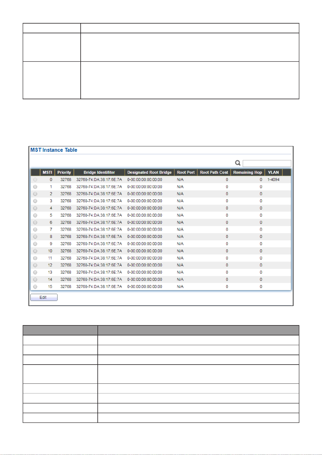
III 3.-7- MST Instance
To congure MST instance seng, click STP > MST Instance.
Figure 62 - Spanning Tree > MST Instance
Item
Descripon
MSTI
Designated port number.
Priority
The bridge priority on the specied MSTI.
Bridge Idener
The bridge idener on the specied MSTI.
Designated Root
Bridge
The designated root bridge idener on the specied MSTI.
Root Port
The designated root port on the specied MSTI.
Root Path Cost
The designated root path cost on the specied MSTI.
Remaining Hop
The conguraon of remaining hop on the specied MSTI.
VLAN
The VLAN conguraon on the specied MSTI.

59
Click " " buon to view Edit MST Instance menu. Edit
Figure 63 - Spanning Tree > MST Instance > Edit MST Instance Seng
Item
Descripon
VLAN
Select the VLAN list for the specied MSTI.
Priority
Specify the bridge priority on the specied MSTI. The valid
range is from 0 to 61440, and the value must be the mulple
of 4096. It ensures the probability that the switch is selected
as the root bridge, and the lower values has the higher
priority for the switch to be selected as the root bridge of
the STP topology.

60
III 4.-7- MST Port Seng
To congure and display MST port seng, click STP > MST Port Seng.
Figure 64 - Spanning Tree > MST Port Seng
Item
Descripon
MSTI
Specify the port seng on the specied MSTI.
Port
Specify the interface ID or the list of interface IDs.
Path Cost
The port path cost on the specied MSTI.
Priority
The port priority on the specied MSTI.
Port Role
The current port role on the specied port. The possible values are:
“Disabled”, “Master”, “Root”, “Designated”, “Alternave”, and
“Backup”.
Port State
The current port state on the specied port. The possible values
are: “Disabled”, “Discarding”, “Learning”, and “Forwarding”.
Mode
The operaonal STP mode on the specied port.
Type
The possible value for the port type are:
Boundary: The port aaching an MST Bridge to a LAN that is
not in the same region.
Internal: The port aaching an MST Bridge to a LAN that is not
in the same region.
Designated
Bridge
The bridge ID of the designated bridge.
Designated
Port ID
The designated port ID on the switch.
Designated
Cost
The path cost of the designated port on the switch.

61
Remaining
Hop
The remaining hops count on the specied port.
Click " " buon to view Edit MST Port Seng menu. Edit
Figure 65 - Spanning Tree > MST Port Seng > Edit MST Port Seng
Item
Descripon
Path Cost
Specify the STP port path cost on the specied MSTI.
Priority
Specify the STP port priority on the specied MSTI.

62
III 5.-7- Stascs
To display the STP stascs, click . STP > Stascs
Figure 66 - Spanning Tree > Stascs
Item
Descripon
Refresh Rate
The opon to refresh the stascs automacally.
Receive BPDU
(Cong)
The counts of the received CONFIG BPDU.
Receive BPDU
(TCN)
The counts of the received TCN BPDU.
Receive BPDU
(MSTP)
The counts of the received MSTP BPDU.
Transmit BPDU
(Cong)
The counts of the transmied CONFIG BPDU.
Transmit BPDU
(TCN)
The counts of the transmied TCN BPDU.
Transmit BPDU
(MSTP)
The counts of the transmied MSTP BPDU.
Clear
Clear the stascs for the selected interfaces
View
View the stascs for the interface.
Click " " buon to view the STP Port Stasc menu. View
64
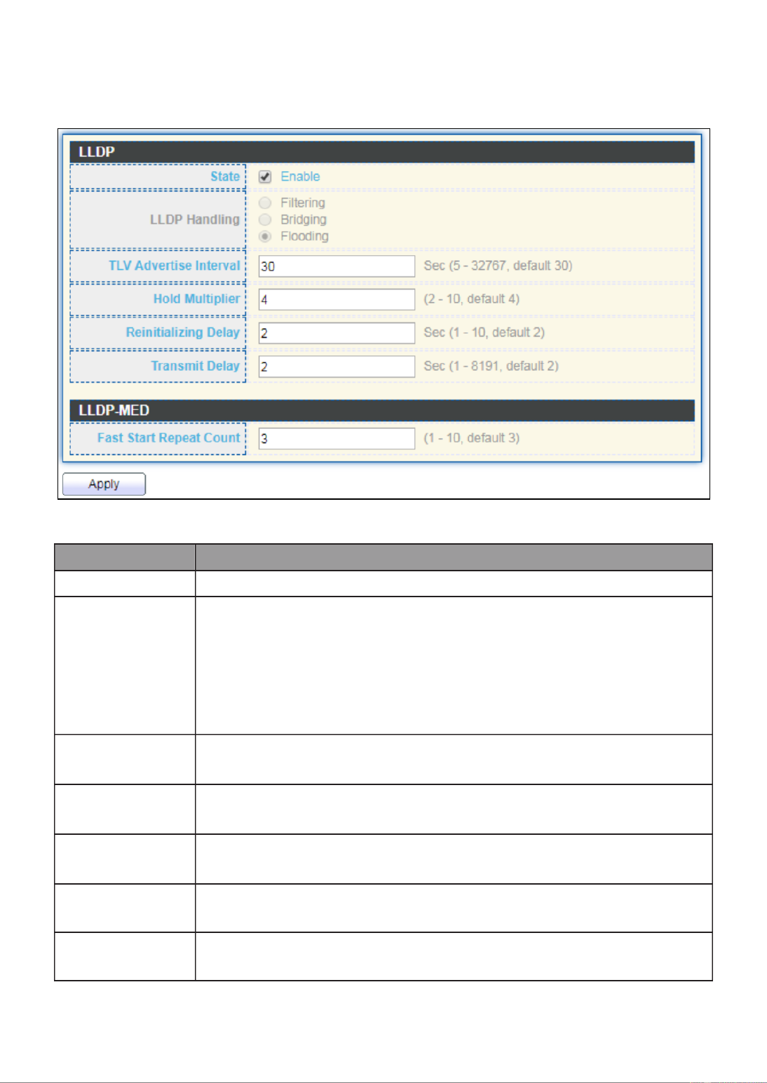
III 1.-8-1- Property
To display LLDP Property Seng web page, click Discovery > LLDP > Property.
Figure 68 - Discovery > LLDP > Property
Item
Descripon
State
Enable/ Disable LLDP protocol on this switch.
LLDP Handling
Select LLDP PDU handling acon to be ltered, bridging or ooded
when LLDP is globally disabled.
Filtering: Deletes the packet.
Bridging: (VLAN-aware ooding) Forwards the packet to all
VLAN members.
Flooding: Forwards the packet to all ports
TLV Adverse
Interval
Select the interval at which frames are transmied. The default is
30 seconds, and the valid range is 5 32767 seconds. –
Holdme
Mulplier
Select the mulplier on the transmit interval to assign to TTL
(range 2 10, default = 4). –
Reinializaon
Delay
Select the delay before a re-inializaon (range 1 10 seconds, –
default = 2).
Transmit
Delay
Select the delay aer an LLDP frame is sent (range 1 8191 –
seconds, default = 3).
Fast Start
Repeat Count
Select fast start repeat count when port link up (range 1–10,
default = 3).

65
III 2.-8-1- Port Seng
To display LLDP Port Seng, click Discovery > LLDP > Port Seng.
Figure 69 - Discovery > LLDP > Port Seng
Item
Descripon
Port
Port Name.
Mode
The port LLDP mode.
Selectde TLV
The Selected LLDP TLV.
Click " " buon to view Edit Port Seng menu. Edit

66
Figure 70 - Discovery > LLDP > Port Seng > Edit Port Seng
Item
Descripon
Port
Select specied port or all ports to congure LLDP state.
Mode
Select the transmission state of LLDP port interface.
Disable: Disable the transmission of LLDP PDUs.
RX Only: Receive LLDP PDUs only.
TX Only: Transmit LLDP PDUs only.
TX And RX: Transmit and receive LLDP PDUs both.
Oponal
TLV
Select the LLDP oponal TLVs to be carried (mulple selecon is
allowed).
System Name
Port Descripon
System Descripon
System Capability
802.3 MAC-PHY
802.3 Link Aggregaon
802.3 Maximum Frame Size
Management Address
802.1 PVID.
802.1 VLAN
Name
Select the VLAN Name ID to be carried (mulple selecon is
allowed).
67
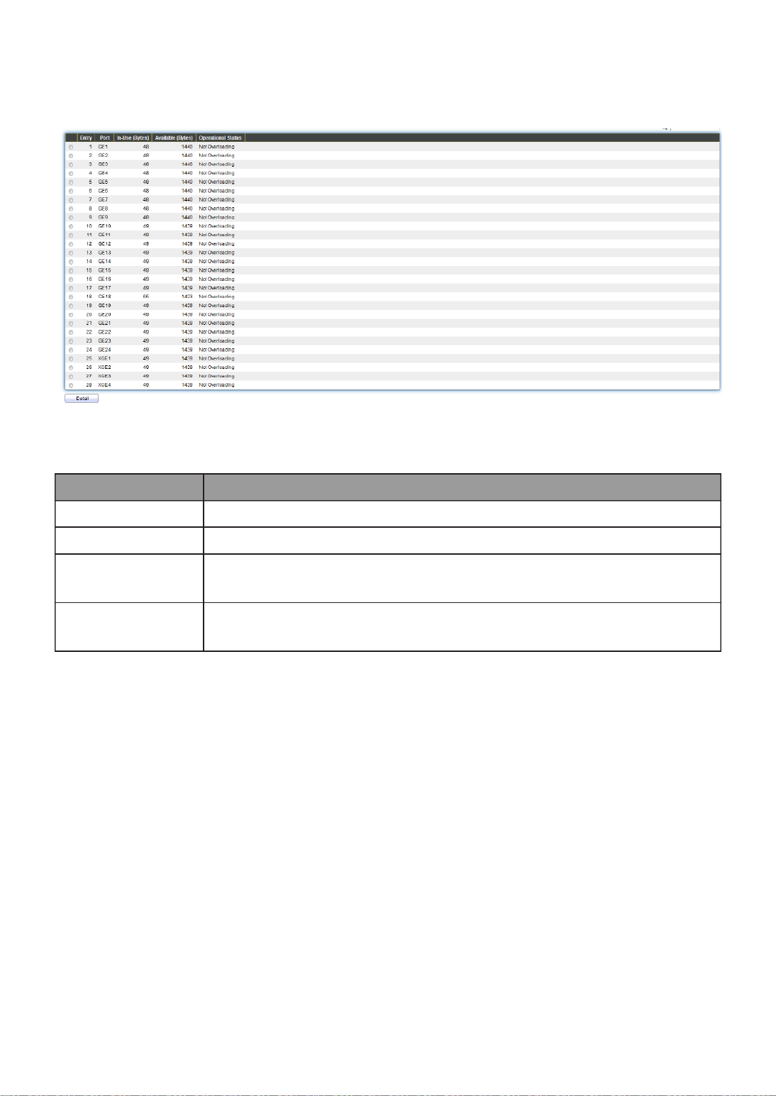
III 3.-8-1- Packet View
To display LLDP Overloading, click Discovery > LLDP > Packet View.
Figure 71 - Discovery > LLDP > Packet View
Item
Description
Port
Port Name.
In-Use (Bytes)
Total number of bytes of LLDP informaon in each packet.
Available
(Bytes)
Total number of available bytes le for addional LLDP
informaon in each packet.
Operaonal
Status
Overloading or not.
Click " " buon to view Packet View Detail menu. Detail
68

69
Figure 72 - Discovery > LLDP > Packet View > Packet View Detail
Item
Descripon
Port
Port Name.
Mandatory TLVs
Total mandatory TLV byte size. Status is sent or
overloading.
MED Capabilies
Total MED Capabilies TLV byte size. Status is sent or
overloading.
MED Locaon
Total MED Locaon byte size. Status is sent or
overloading.
MED Network Policy
Total MED Network Policy byte size. Status is sent or
overloading.
MED Inventory
Total MED Inventory byte size. Status is sent or
overloading
MED Extended Power
via MDI
Total MED Extended Power via MDI byte size. Status is
sent or overloading.
802.3 TLVs
Total 802.3 TLVs byte size. Status is sent or overloading.
Oponal TLVs
Total Oponal TLV byte size. Status is sent or
overloading.
802.1 TLVs
Total 802.1 TLVs byte size. Status is sent or overloading.
Total
Total number of bytes of LLDP informaon in each
packet.

70
III 4.-8-1- Local Informaon
Use the LLDP Local Information to view LLDP local device information.
To display LLDP Local Device, click Discovery > LLDP > Local Informaon.
Figure 73 - Discovery > LLDP > Local Information
Item
Descripon
Chassis ID
Subtype
Type of chassis ID, such as the MAC address.
Chassis ID
Identifier of chassis. Where the chassis ID subtype is a MAC
address, the MAC address of the switch is displayed.
System Name
Name of switch.
System
Description
Description of the switch.
Capabilities
Supported
Primary functions of the device, such as Bridge, WLAN AP, or
Router.
Capabilities
Enabled
Primary enabled functions of the device.
Port ID
Subtype
Type of the port identifier that is shown.

71
LLDP Status
LLDP Tx and Rx abilities.
LLDP Med
Status
LLDP MED enable state.
Click “ ” buon on the page to view detail informaon of the selected port.Detail

72
Figure 74 - Discovery > LLDP > Local Informaon > Detail
III 5.-8-1- Neighbor
Use the LLDP Neighbor page to view LLDP neighbors informaon.
To display LLDP Remote Device, click Discovery > LLDP > Neighbor.
Figure 75 - Discovery > LLDP > Neighbor

73
Item
Descripon
Local Port
Number of the local port to which the neighbor is connected.
Chassis ID Subtype
Type of chassis ID (for example, MAC address).
Port ID Subtype
Type of the port idener that is shown.
Port ID
Idener of port.
System Name
Published name of the switch.
Time to Live
Time interval in seconds aer which the informaon for this
neighbor is deleted.
Click “ ” to view selected neighbor detail informationdetail

74

75
Figure 76 LLDP Neighbor Detail Page

76
III 6.-8-1- Stascs
The Link Layer Discovery Protocol (LLDP) Stascs page displays summary and per-port
informaon for LLDP frames transmied and received on the switch.
To display LLDP Stascs status, click Discovery > LLDP > Stascs.
Figure 77 - Discovery > LLDP > Stascs
Item
Descripon
Inserons
The number of mes the complete set of informaon adversed
by a parcular MAC Service Access Point (MSAP) has been
inserted into tables associated with the remote systems.
Deleons
The number of mes the complete set of informaon adversed
by MSAP has been deleted from tables associated with the remote
systems.
Drops
The number of mes the complete set of informaon adversed
by MSAP could not be entered into tables associated with the
remote systems because of insucient resources.
Age Outs
The number of mes the complete set of informaon adversed

77
by MSAP has been deleted from tables associated with the remote
systems because the informaon meliness interval has expired.
Stascs Table
Port
Interface or port number.
Transmit
Frame Total
Number of LLDP frames transmied on the corresponding port.
Receive
Frame Total
Number of LLDP frames received by this LLDP agent on the
corresponding port, while the LLDP agent is enabled.
Receive
Frame Discard
Number of LLDP frames discarded for any reason by the LLDP
agent on the corresponding port.
Receive
Frame Error
Number of invalid LLDP frames received by the LLDP agent on the
corresponding port, while the LLDP agent is enabled.
Receive TLV
Discard
Number of TLVs of LLDP frames discarded for any reason by the
LLDP agent on the corresponding port.
Receive TLV
Unrecognized
Number of TLVs of LLDP frames that are unrecognied while the
LLDP agent is enabled.
Neighbor
Timeout
Number of age out LLDP frames.
III 9.- Mulcast
Use this secon to congure Mulcast.
III 1.-9- General
Use the General pages to congure seings of IGMP and MLD common funcon.
III 1.-9-1- Property
To display mulcast general property Seng web page, click Mulcast> General>
Property.

78
Figure 78 - Mulcast > General > Property
Item
Description
Unknown
Mulcast
Acon
Set the unknown mulcast acon
Flood: ood the unknown mulcast data.
Drop: drop the unknown mulcast data.
Router port: forward the unknown mulcast data to router
port.
IPv4
Set the ipv4 mulcast forward method.
MAC-VID: forward method dmac+vid.
DIP-VID: forward method dip+vid.
IPv6
MAC-
DIP-VID: forward method dip+vid(dip is ipv6 low 32 bit).
III 2.-9-1- Group Address
This page allow user to browse all mulcast groups that dynamic learned or stacally
added.
To display Mulcast General Group web page, click Multicast> General > Group Address.
Figure 79 - Mulcast > General > Group Address

79
Item Descripon
IP Version
IP Version
IPv4: ipv4 multicast group
IPv6: ipv6 multicast group
VLAN
The VLAN ID of group.
Group Address
The group IP address.
Member
The member ports of group.
Type
The type of group. Static or Dynamic.
Life(Sec)
The life time of this dynamic group.
Click “ ” or “Add Edit” button to view Add or Edit Group Address menu.
Figure 80 - Multicast > General > Group Address > Add/Edit Group Address
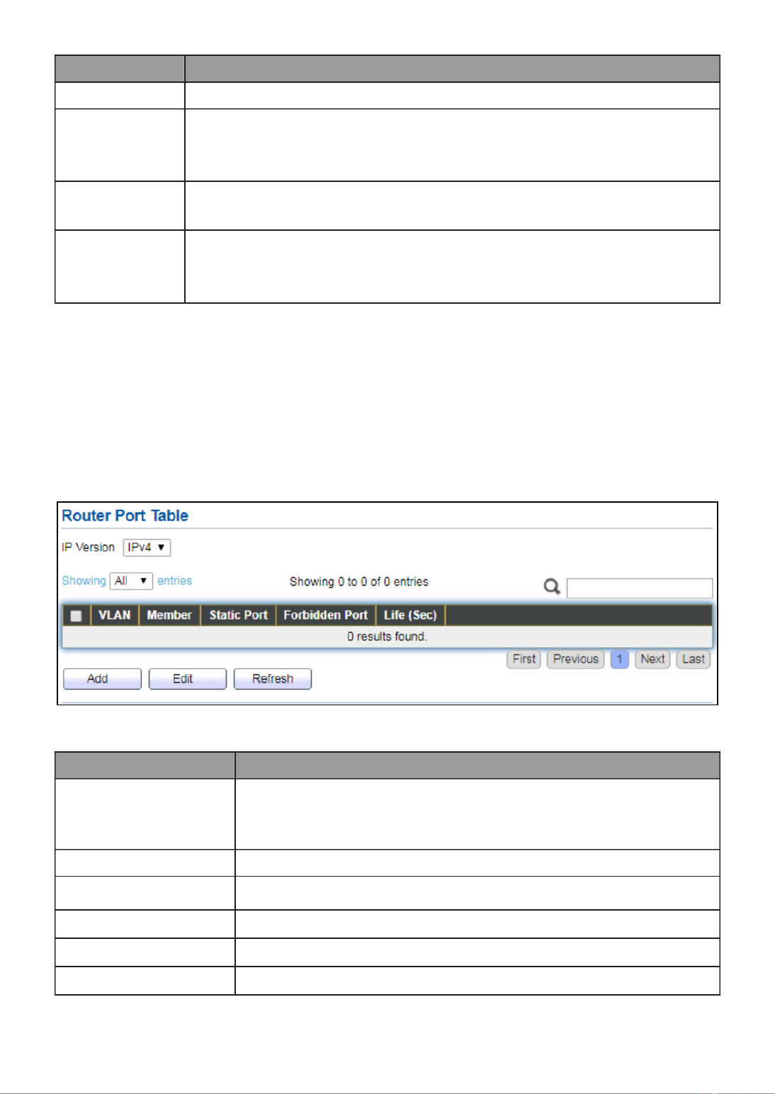
80
Item
Description
VLAN
The VLAN ID of group.
IP Version
IP Version
IPv4: ipv4 mulcast group
IPv6: ipv6 mulcast group
Group
Address
The group IP address.
Member
The member ports of group.
Available Port: Oponal port member
Selected Port: Selected port member
III 3.-9-1- Router Port
This page allow user to browse all router port informaon. The stac and forbidden
router port can set by user.
To display mulcast router port table web page, click Multicast > General > Router Port.
Figure 81 - Mulcast > General > Router Port
Item
Description
IP Version
IP Version
IPv4: ipv4 mulcast router
IPv6: ipv6 mulcast router
VLAN
The VLAN ID router entry.
Member
Router Port member (include stac and learned port
member)
Stac Port
Stac router port member.
Forbidden Port
Forbidden router port member.
Life (Sec)
The expiry me of the router entry.
Click "Add" or “Edit” button to view Add/Edit Router Port menu.

81
Figure 82 - Mulcast > General > Router Port > Add/Edit Router Port

82
Item
Descripon
VLAN
The VLAN ID for router entry
Available VLAN: Oponal VLAN member
Selected VLAN: Selected VLAN member.
IP Version
IP Version
IPv4: ipv4 mulcast router
IPv6: ipv6 mulcast router
Type
The router port type
Stac: stac router port
Forbidden: forbidden router port, can’t learn dynamic
router port member
Port
The member ports of router entry.
Available Port: Oponal router port member
Selected Port: Selected router port member
III 2.-9- IGMP Snooping
Use the IGMP Snooping pages to congure sengs of IGMP snooping funcon.
III 1.-9-2- Property
This page allow user to congure global seings of IGMP snooping and congure specic
VLAN sengs of IGMP Snooping.
To display IGMP Snooping global seng and VLAN Seng web page, click Mulcast >
IGMP Snooping > Property.
Figure 83 - Mulcast > IGMP Snooping > Property

83
Item
Descripon
State
Set the enabling status of IGMP Snooping functionality
Enable: If Checked Enable IGMP Snooping, else is Disabled
IGMP Snooping.
Version
Set the igmp snooping version
IGMPv2: Only support process igmp v2 packet.
IGMPv3: Support v3 basic and v2.
Report Suppression
Set the enabling status of IGMP v2 report suppression
Enable: If Checked Enable IGMP Snooping v2 report
suppression, else Disable the report suppression function.
VLAN
The IGMP entry VLAN ID.
Operation Status
The enable status of IGMP snooping VLAN functionality.
Router Port Auto
Learn
The enabling status of IGMP snooping router port auto
learning.
Query Robustness
The Query Robustness allows tuning for the expected packet
loss on a subnet.
Query Interval
The interval of querier to send general query.
Query Max
Response
Interval
In Membership Query Messages, it specifies the maximum
allowed time before sending a responding report in units of
1/10 second.
Last Member
Query count
The count that Querier-switch sends Group-Specific Queries
when it receives a Leave Group message for a group.
Last Member
Query Interval
The interval that Querier-switch sends Group-Specific
Queries when it receives a Leave Group message for a group.
Immediate leave
The immediate leave status of the group will immediate
leave when receive IGMP Leave message.
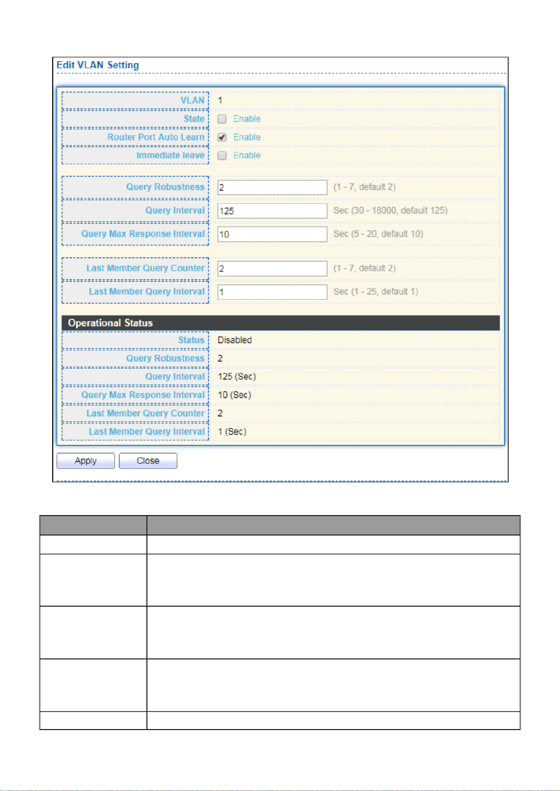
84
Click " " button to Edit VLAN Setting menu. Edit
Figure 84 - Multicast > IGMP Snooping > Property >Edit VLAN Setting
Item
Description
VLAN
The selected VLAN List.
State
Set the enabling status of IGMP Snooping VLAN functionality
Enable: If Checked Enable IGMP Snooping VLAN, else is Disabled
IGMP Snooping VLAN.
Router Port
Auto Learn
Set the enabling status of IGMP Snooping router port learning
Enable: If checked Enable learning router port by query and PIM,
DVRMP, else Disable the learning router port.
Immediate
leave
Immediate Leave the group when receive IGMP Leave message.
Enable: If checked Enable immediate leave, else disable
immediate leave.
Query
The Admin Query Robustness allows tuning for the expected

85
Robustness
packet loss on a subnet.
Query Interval
The Admin interval of querier to send general query.
Query Max
Response
Interval
The Admin query max response interval In Membership Query ,
Messages, it species the maximum allowed me before sending
a responding report in units of 1/10 second.
Last Member
Query Counter
The Admin last member query count that Querier-switch sends
Group-Specic Queries when it receives a Leave Group message
for a group.
Last Member
Query
Interval
The Admin last member query interval that Querier-switch
sends Group-Specic Queries when it receives a Leave Group
message for a group.
Operaonal Status
Status
Operaonal IGMP snooping status must both IGMP snooping ,
global and IGMP snooping enable the status will be enable.
Query
Robustness
Operaonal Query Robustness.
Query Interval
Operaonal Query Interval.
Query Max
Response
Interval
Operaonal Query Max Response Interval
Last Member
Query
Counter
Operaonal Last Member Query Count.
Last Member
Query
Interval
Operaonal Last Member Query Interval.
III 2.-9-2- Querier
This page allow user to congure querier seings on specic VLAN of IGMP Snooping.
To display IGMP Snooping Querier Setng web page, click Mulcast > IGMP Snooping >
Querier.

86
Figure 85 - Multicast > IGMP Snooping > Querier
Item
Descripon
VLAN
IGMP Snooping querier entry VLAN ID.
State
The IGMP Snooping querier Admin State.
Operational Status
The IGMP Snooping querier operational status.
Querier Version
The IGMP Snooping querier operational version.
Querier IP
The operational Querier IP address on the VLAN.
Click " " button to view Edit Querier menu. Edit
Figure 86 - Multicast > IGMP Snooping > Querier > Edit Querier
Item
Descripon
VLAN
The Selected Edit IGMP Snooping querier VLAN List.
State
Set the enabling status of IGMP Querier Election on the
chose VLANs
Enabled: if checked Enable IGMP Querier else Disable IGMP
Querier.
Version
Set the query version of IGMP Querier Election on the chose
VLANs
IGMPv2: Querier version 2.
IGMPv3: Querier version 3. (IGMP Snooping version
should be IGMPv3)

87
III 3.-9-2- Stascs
This page allow user to clear igmp snooping stacs.
To display IGMP Snooping Stascs, click Mulcast > IGMP Snooping > Stascs.
Figure 87 - Mulcast > IGMP Snooping > Stascs
Item
Descripon
Receive Packet
Total
Total RX igmp packet, include ipv4 mulcast data to CPU.
Valid
The valid igmp snooping process packet.
InValid
The invalid igmp snooping process packet.
Other
The ICMP protocol is not 2, and is not ipv4 mulcast data packet.
Leave
IGMP leave packet.
Report
IGMP join and report packet.
General Query
IGMP General Query packet.
Special Group
Query
IGMP Special Group General Query packet.

88
Source-specic
Group Query
IGMP Special Source and Group General Query packet.
Transmit Packet
Leave
IGMP leave packet
Report
IGMP join and report packet
General Query
IGMP general query packet include querier transmit general
query packet.
Special Group
Query
IGMP special group query packet include querier transmit special
group query packet.
Source-specic
Group Query
IGMP Special Source and Group General Query packet.
III 3.-9- MVR
Use the MVR pages to congure seings of MVR funcon.
III 1.-9-3- Property
To display mulcast MVR property Seng web page, click Mulcast > MVR > Property.
Figure 88 - Mulcast > MVR > Property
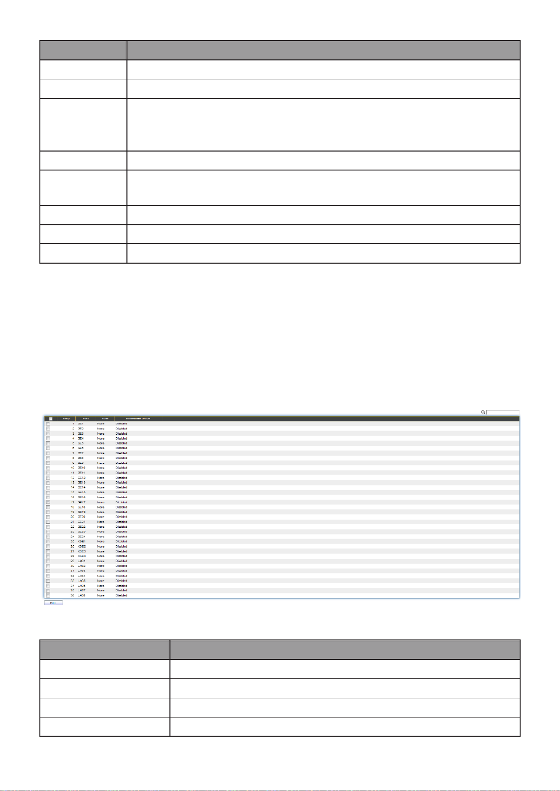
89
Item
Descripon
State
Enable: if checked enable the MVR state, else disable the MVR state.
VLAN
The MVR VLAN ID.
Mode
Set the MVR mode
Compable: compable mode.
Dynamic: learn group member on source port.
Group Start
MVR group range start.
Group
Count
MVR group connue count.
Query Time
MVR query me when receive MVR leave MVR group packet.
Maximum
The max number of MVR group database.
Current
The learned MVR group current me
III 2.-9-3- Port Seng
This page allow user to congure port role and port immediate leave.
To display MVR port role and immediate leave state seing web page, click Mulcast >
MVR > Port Seng.
Figure 89 - Mulcast > MVR > Port Seng
Item
Descripon
Entry
Entry of number.
Port
Port Name.
Role
Port Role for MVR, the type is None/Receiver/Source.
Immediate Leave
Status of immediate leave.
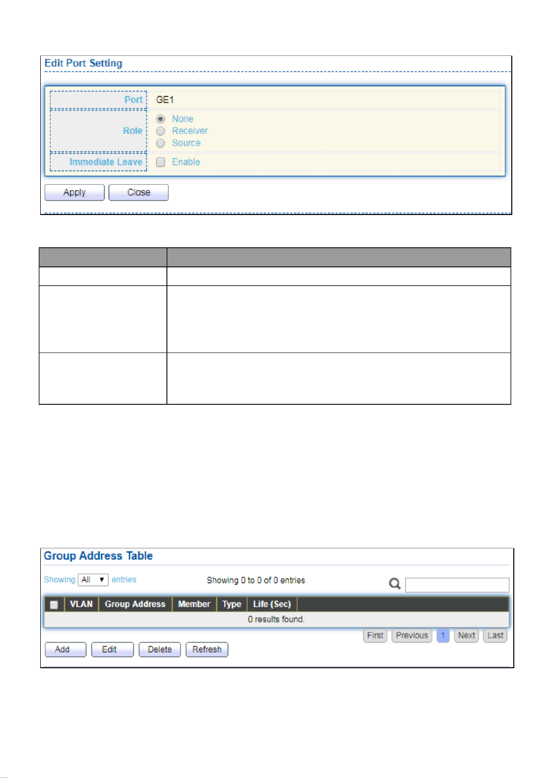
90
Click " " buon to view Edit Port Seng menu. Edit
Figure 90 - Mulcast > MVR > Port Seng > Edit Port Seng
Item
Description
Port
Display the selected port list.
Role
MVR port role
None: port role is none.
Receiver: port role is receiver.
Source: port role is source.
Immediate Leave
MVR Port immediate leave
Enable: if checked is enable immediate leave, else disable
immediate leave.
III 3.-9-3- Group Address
This page allow user to browse all mulcast MVR groups that dynamic learned or
stacally added.
To display Mulcast MVR Group web page, click Multicast > MVR > Group Address.
Figure 91 - Mulcast > MVR > Group Address

91
Item
Descripon
VLAN
The VLAN ID of MVR group.
Group
Address
The MVR group IP address.
Member
The member ports of MVR group.
Type
The type of MVR group. Static or Dynamic.
Life(Sec)
The life time of this dynamic MVR group.
Click " " button to view Add/Edit Group Address Table menu. Add
Figure 92 - Multicast > MVR > Group Address > Add Group Address
Item
Descripon
VLAN
The VLAN ID of MVR group.
Group
Address
The MVR group IP address.
Member
The member ports of MVR group.
Available Port: Optional port member, it is only receiver port
when MVR mode is compatible, it include source port when
mode is dynamic.
Selected Port: Selected port member
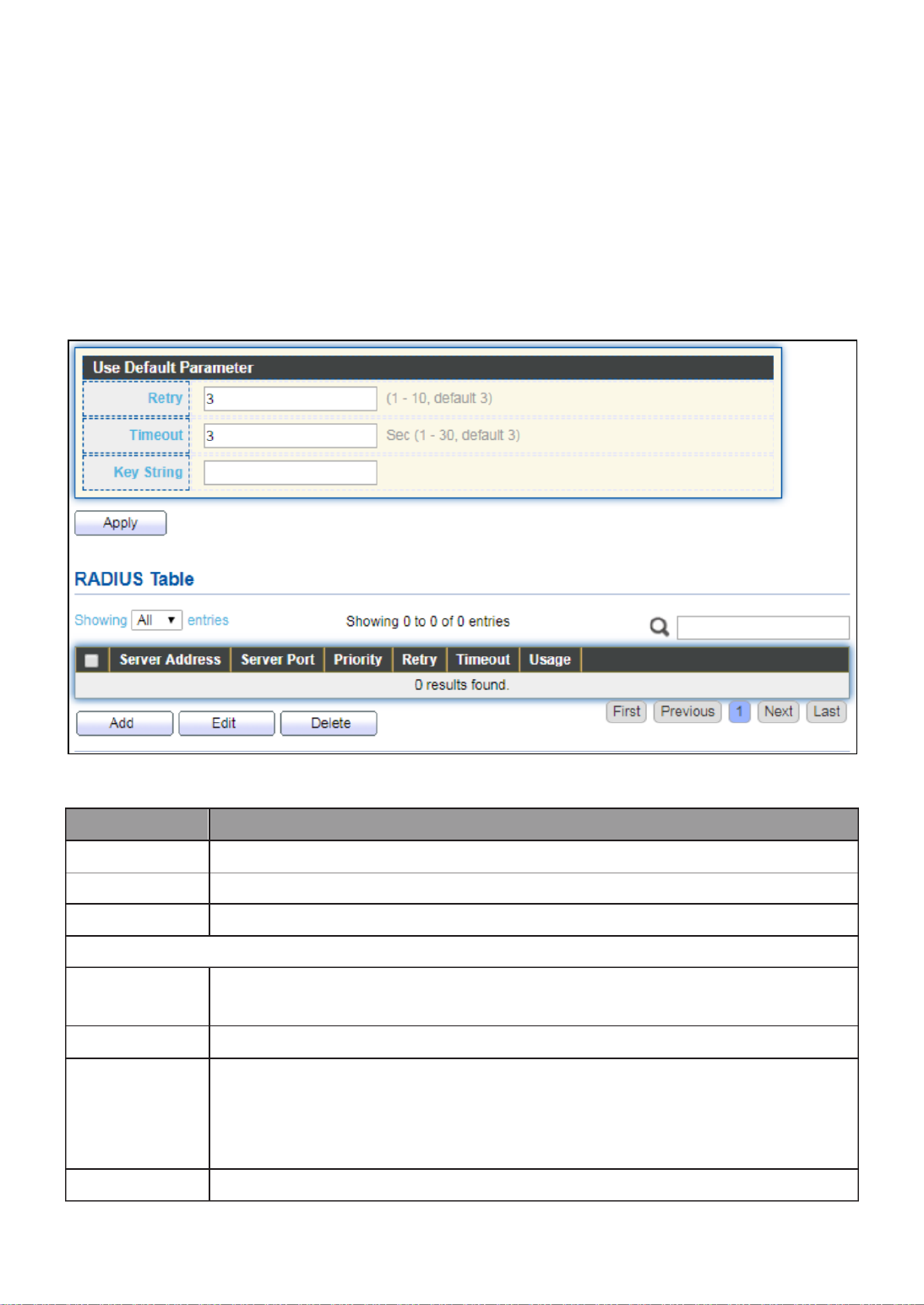
92
III 10.- Security
Use the Security pages to congure sengs for the switch security features.
III 10 1.- - RADIUS
This page allow user to add, edit or delete RADIUS server sengs and modify default
parameter of RADIUS server.
To display RADIUS web page, click Security > RADIUS.
Figure 93 - Security > RADIUS
Item
Description
Retry
Set default retry number.
Timeout
Set default meout value.
Key String
Set default RADIUS key string
RADIUS Table
Server
Address
RADIUS server address.
Server Port
RADIUS server port.
Priority
RADIUS server priority (smaller value has higher priority). RADIUS
session will try to establish with the server seng which has highest
priority. If failed, it will try to connect to the server with next higher
priority.
Retry
RADIUS server retry value. If it is fail to connect to server, it will keep

93
trying until timeout with retry times.
Timeout
RADIUS server timeout value. If it is fail to connect to server, it will
keep trying until timeout.
Usage
RADIUS server usage type
Login: For login authentifation.
802.1x: For 802.1x authentication.
All: For all types.
Click "Add" or “Edit” button to view Add/Edit RADIUS Server menu.

94
Figure 94 - Security > RADIUS > Add/Edit RADIUS Server
Item
Descripon
Address Type
In add dialog, user need to specify server Address Type
Hostname: Use domain name as server address.
IPv4: Use IPv4 as server address.
IPv6: Use IPv6 as server address.
Server Address
In add dialog, user need to input server address based on
address type. In edit dialog, it shows current edit server
address.
Server Port
Set RADIUS server port.
Priority
Set RADIUS server priority (smaller value has higher priority).
RADIUS session will try to establish with the server setting
which has highest priority. If failed, it will try to connect to
the server with next higher priority.
Retry
Set RADIUS server retry value. If it is fail to connect to server,
it will keep trying until timeout with retry times.
Timeout
Set RADIUS server timeout value. If it is fail to connect to
server, it will keep trying until timeout.
Usage
Set RADIUS server usage type
Login: For login authentifation.
802.1x: For 802.1x authentication.
All: For all types.

95
III 10 2.- - Management Access
Use the Management Access pages to congure seings of management access.
III 10 1.- -2- Management VLAN
Note: Change Management VLAN may cause connection interrupted
III 10 2.- -2- Management Service
This page allow user to change management services related conguraons.
To display Management Service click Security > Management Access > Management
Service.

96
Figure 95 - Security > Management Access > Management Service

97
Item Descripon
Management
Service
Management service admin state.
Telnet: Connect CLI through telnet.
SSH: Connect CLI through SSH.
HTTP: Connect WEBUI through HTTP.
HTTPS: Connect WEBUI through HTTPS.
SNMP: Manage switch trough SNMP.
Session
Timeout
Set session meout minutes for user access to user interface. 0
minutes means never meout.
Password
Retry
Count
Retry count is the number which CLI password input error
tolerance count. Aer input error password exceeds this count, the
CLI will freeze aer silent me.
Silent Time
Aer input error password exceeds password retry count, the CLI
will freeze aer silent me.
III 10 3.- -2- Management ACL
This page allow user to add or delete management ACL rule. A rule cannot be deleted if
under acve.
To display Management ACL page, click Security > Management Access > Management
ACL.
Figure 96 - Security > Management Access > Management ACL
Item
Descripon
ACL Name
Input MAC ACL name.
Management ACL
ACL Name
Display Management ACL name.
State
Display Management ACL whether acve.
Rule
Display the number Management ACE rule of ACL.

99
Click "Add" or “Edit” buon to view Add/Edit Management ACE menu.

100
Figure 98 - Security > Management Access > Add/Edit Management ACE
Item
Descripon
ACL Name
Display the ACL name to which an ACE is being added.
Priority
Specify the priority of the ACE. ACEs with higher sequence are
processed rst (1 is the highest priority). Only available on Add
Dialog.
Service
Select the type service of rule.
All: All services.
HTTP: Only HTTP service.
HTTPs: Only HTTPs service
SNMP: Only SNMP service.
SSH: Only SSH service.
Telnet: Only Telnet service
Acon
Select the acon aer ACE match packet.
Permit: Forward packets that meet the ACE criteria.

101
Deny: Drop packets that meet the ACE criteria.
Port
Select ports which will be matched.
IP Version
Select the type of source IP address.
All: All IP addresses can access.
IPv4: Specify IPv4 address ca access.
IPv6: Specify IPv6 address ca access.
IPv4
Enter the source IPv4 address value and mask to which will be
matched.
IPv6
Enter the source IPv6 address value and mask to which will be
matched.
III 10 3.- - Authencaon Manager
III 10 1.- -3- Property
This page allow user to edit authentication global settings and some port mods’
conguraons.
To display authencaon manager Property web page, click Security > Authencaon
Manager > Property.
Figure 99 - Security > Authencaon Manager > Property

102
Item
Descripon
Authencaon
Type
Set checkbox to enable/disable following authencaon types
802.1x: Use IEEE 802.1x to do authencaon
MAC-Based: Use MAC address to do authencaon
WEB-Based: Prompt authencaon web page for user to do
authencaon
Guest VLAN
Set checkbox to enable/disable guest VLAN, if guest VLAN is
enabled, you need to select one available VLAN ID to be guest
VID.
MAC-Based
User
ID Format
Select mac-based authencaon RADIUS username/password ID
format.
XXXXXXXXXXXX
Xxxxxxxxxxxx
XX:XX:XX:XX:XX:XX
xx:xx:xx:xx:xx:xx
XX XX XX- - -XX- - XX XX
xx xx xx- - - - - xx xx xx
XX.XX.XX.XX.XX.XX
xx.xx.xx.xx.xx.xx
XXXX:XXXX:XXXX
xxxx:xxxx:xxxx
XXXX-XXXX-XXXX
XXXX-XXXX-XXXX
XXXX.XXXX.XXXX
XXXX.XXXX.XXXX
XXXXXX:XXXXXX
XXXXXX:XXXXXX
XXXXXX-XXXXXX
XXXXXX-XXXXXX
Port Mode Table
Port
Port Name.
Authencaon
Type
(802.1X)
802.1X authencaon type state
Enabled: 802.1X is enabled.
Disabled: 802.1X is disabled.
Authencaon
Type
(MAC-Based)
MAC-Based authencaon type state
Enabled: MAC-Based authencaon is enabled
Disabled: MAC-Based authencaon is disabled
Authencaon
Type
(WEB-Based)
WEB-Based authencaon type state
Enabled: WEB-Based authencaon is enabled
Disabled: WEB-Based authencaon is disabled
Host Mode
Authencang host mode

103
Multiple Authentication: In this mode, every client need to
pass authenticate procedure individually.
Multiple Hosts: In this mode, only one client need to be
authenticated and other clients will get the same access
accessibility. Web-auth cannot be enabled in this mode.
Single Host: In this mode, only one host is allowed to be
authenticated. It is the same as Multi-auth mode with max
hosts number configure to be 1.
Order
Support following authentication type order combinations. Web
Authentication should always be the last type. The authentication
manager will go to next type if current type is not enabled or
authenticated fail.
802.1x
MAC-Based
WEB-Based
802.1x MAC-Based
802.1x WEB-Based
MAC-Based 802.1x
WEB-Based 802.1x
802.1x MAC-Based WEB-Based
802.1x WEB-Based MAC-Based
Method
Support following authentication method order combinations.
These orders only available on MAC-Based authentication and
WEB-Based authentication. 802.1x only support Radius method.
Local: Use DUT’s local database to do authentication
Radius: Use remote RADIUS server to do authentication
Local Radius
Radius Local
Guest VLAN
Port guest VLAN enable state
Enabled: Guest VLAN is enabled on port.
Disabled: Guest VLAN is disabled on port.
VLAN Assign
Mode
Support following VLAN assign mode and only apply when source
is RADIUS
Disable: Ignore the VLAN authorization result and keep
original VLAN of host.
Reject: If get VLAN authorized information, just use it.
However, if there is no VLAN authorized information, reject
the host and make it unauthorized.
Static: If get VLAN authorized information, just use it. If there
is no VLAN authorized information, keep original VLAN of
host.

104
Click “ ” button to view the Edit Port Mode menu.Edit
Figure 100 - Security > Authentication Manager > Property > Edit Port Mode
Item
Description
Port
Selected port list.
Authentication
Type
Set checkbox to enable/disable authentication types.
Host Mode
Select authenticating host mode
Multiple Authentication: In this mode, every client need to
pass authenticate procedure individually.
Multiple Hosts: In this mode, only one client need to be
authenticated and other clients will get the same access
accessibility. Web-auth cannot be enabled in this mode.
Single Host: In this mode, only one host is allowed to be

105
authenticated. It is the same as Multi-auth mode with max
hosts number configure to be 1.
Order
Support following authentication type order combinations. Web
Authentication should always be the last type. The
authentication manager will go to next type if current type is
not enabled or authenticated fail.
802.1x
MAC-Based
WEB-Based
802.1x MAC-Based
802.1x WEB-Based
MAC-Based 802.1x
WEB-Based 802.1x
802.1x MAC-Based WEB-Based
802.1x WEB-Based MAC-Based
Method
Support following authentication method order combinations.
These orders only available on MAC-Based authentication and
WEB-Based authentication. 802.1x only support Radius method.
Local: Use DUT’s local database to do authentication.
Radius: Use remote RADIUS server to do authentication.
Local Radius.
Radius Local.
Guest VLAN
Set checkbox to enable/disable guest VLAN.
VLAN Assign
Mode
Support following VLAN assign mode and only apply when
source is RADIUS
Disable: Ignore the VLAN authorization result and keep
original VLAN of host.
Reject: If get VLAN authorized information, just use it.
However, if there is no VLAN authorized information, reject
the host and make it unauthorized.
Static: If get VLAN authorized information, just use it. If
there is no VLAN authorized information, keep original
VLAN of host.

106
III 10 2.- -3- Port Setting
This page allow user to configure authentication manger port settings
To display the authentication manager Port Setting web page, click Security >
Authentication Manager > Port Setting.
Figure 101 - Security > Authentication Manager > Port Setting
Item
Description
Port
Port
Port Control
Support following authentication port control types.
Disable: Disable authentication function and all clients
have network accessibility.
Force Authorized: Port is force authorized and all clients
have network accessibility.
Force Unauthorized: Port is force unauthorized and all
clients have no network accessibility.
Auto: Need passing authentication procedure to get
network accessibility.
Reauthentication
Reautheticate state
Enabled: Host will be reauthenticated after
reauthentication period.
Disabled: Host will not be reauthenticated after
reauthentication period.
Max Hosts
In Multiple Authentication mode, total host number cannot
not exceed max hosts number.
Common Timer
After re-authenticate period, host will return to initial state

107
(Reauthentication)
and need to pass authentication procedure again.
Common Timer
(Inactive)
If no packet from the authenticated host, the inactive timer
will increase. After inactive timeout, the host will be
unauthorized and corresponding session will be deleted. In
multi-host mode, the packet is counting on the authorized
host only.
Common Timer
(Quiet)
When port is in Locked state after authenticating fail several
times, the host will be locked in quiet period. After this quiet
period, the host is allowed to authenticate again.
802.1X Params
(TX Period)
Number of seconds that the device waits for a response to an
Extensible Authentication Protocol (EAP) request/identity
frame from the supplicant (client) before resending the
request.
802.1X Params
(Supplicant
Timeout)
The maximum number of EAP requests that can be sent. If a
response is not received after the defined period (supplicant
timeout), the authentication process is restarted.
802.1X Params
(Server Timeout)
Number of seconds that lapses before EAP requests are
resent to the supplicant.
802.1X Params
(Max Request)
Number of seconds that lapses before the device resends a
request to the authentication server.
Web-Based Param
(Max Login)
Allow user login fail number. After login fail number exceed,
the host will enter Lock state and is not able to authenticate
until quiet period exceed.

108
Click " " button to view Edit Port Setting menu. Edit
Figure 102 - Security > Authentication Manager > Port Setting > Edit Port Setting
Item
Description
Port
Port Name.
Port Control
Support following authentication port control types.
Disable: Disable authentication function and all clients have
network accessibility.Force Authorized: Port is force
authorized and all clients have network accessibility.
Force Unauthorized: Port is force unauthorized and all
clients have no network accessibility.
Auto: Need passing authentication procedure to get
network accessibility.
Reauthentication
Set checkbox to enable/disable reuauthentication.

110
Item
Description
Session ID
Session ID is unique of each session.
Port
Port name which the host located.
MAC Address
Host MAC address.
Current Type
Show current authenticating type
802.1x: Use IEEE 802.1X to do authenticating
MAC-Based: Use MAC-Based authentication do to
authenticating.
WEB-Based: Use WEB-Based authentication to do
authenticating.
Status
Show host authentication session status
IP version (IPv4, IPv6)
Disable: This session is ready to be deleted
Running: Authentication process is running
Authorized: Authentication is passed and getting network
accessibility.
UnAuthorized: Authentication is not passed and not
getting network accessibility.
Locked: Host is locked and do not allow to do
authenticating until quiet period.
Guest: Host is in the guest VLAN.
Operational
(VLAN)
Shows host operational VLAN ID.
Operational
(Session Time)
In “Authorized” state, it shows total time after authorized.
Operational
(Inactived)
In “Authorized” state, it shows how long the host do not send
any packet.
Operational
(Quiet Time)
In “Locked” state, it shows total time after locked.
Authorized
(VLAN)
Shows VLAN ID given from authorized procedure.
Authorized
(Reauthentication
Period)
Shows reauthentication period given from authorized
procedure.
Authorized
(Inactive
Timeouts)
Shows inactive timeout given from authorized procedure.

111
III 10 4.- - Port Security
This page allow user to configure port security settings for each interface. When port
security is enabled on interface, action will be perform once learned MAC address over
limitation.
To display Port Security web page, click Security > Port Security.
Figure 104 - Security > Port Security
Item
Description
State
Enable/Disable the port security function.
Port
Select one or multiple ports to configure.
State
Select the status of port security
Disable: Disable port security function.
Enable: Enable port security function.
MAC
Address
Specify the number of how many mac addresses can be learned.
Action
Select the action if learned mac addresses
Forward: Forward this packet whose SMAC is new to system
and exceed the learning-limit number.
Discard: Discard this packet whose SMAC is new to system and
exceed the learning-limit number.
Shutdown: Shutdown this port when receives a packet whose
SMAC is new to system and exceed the learning limit number.
Click " " button to view Edit Port Security menu. Edit

112
Figure 105 - Security > Port Security > Edd Port Security
Item
Description
Port
Select one or multiple ports to configure.
State
Select the status of port security
Disable: Disable port security function.
Enable: Enable port security function.
MAC Address
Specify the number of how many mac addresses can be learned.
Action
Select the action if learned mac addresses
Forward: Forward this packet whose SMAC is new to system
and exceed the learning-limit number.
Discard: Discard this packet whose SMAC is new to system
and exceed the learning-limit number.
Shutdown: Shutdown this port when receives a packet whose
SMAC is new to system and exceed the learning limit number.
III 10 5.- - Traffic Segmentati on
Traffic Segmentation prohibits ports to communicate with each other directly, on other
manufacturers’ switches

113

114
III 10 6.- - Storm Control
To display Storm Control global setting web page, click . Security > Storm Control
Figure 108 - Security > Storm Control
Item
Description
Mode(Unit)
Select the unit of storm control
Packet / Sec: storm control rate calculates by packet-based
Kbits / Sec: storm control rate calculates by octet-based.
IFG
Select the rate calculates w/o preamble & IFG (20 bytes)
Excluded: exclude preamble & IFG (20 bytes) when count
ingress storm control rate.
Included: include preamble & IFG (20 bytes) when count
ingress storm control rate.
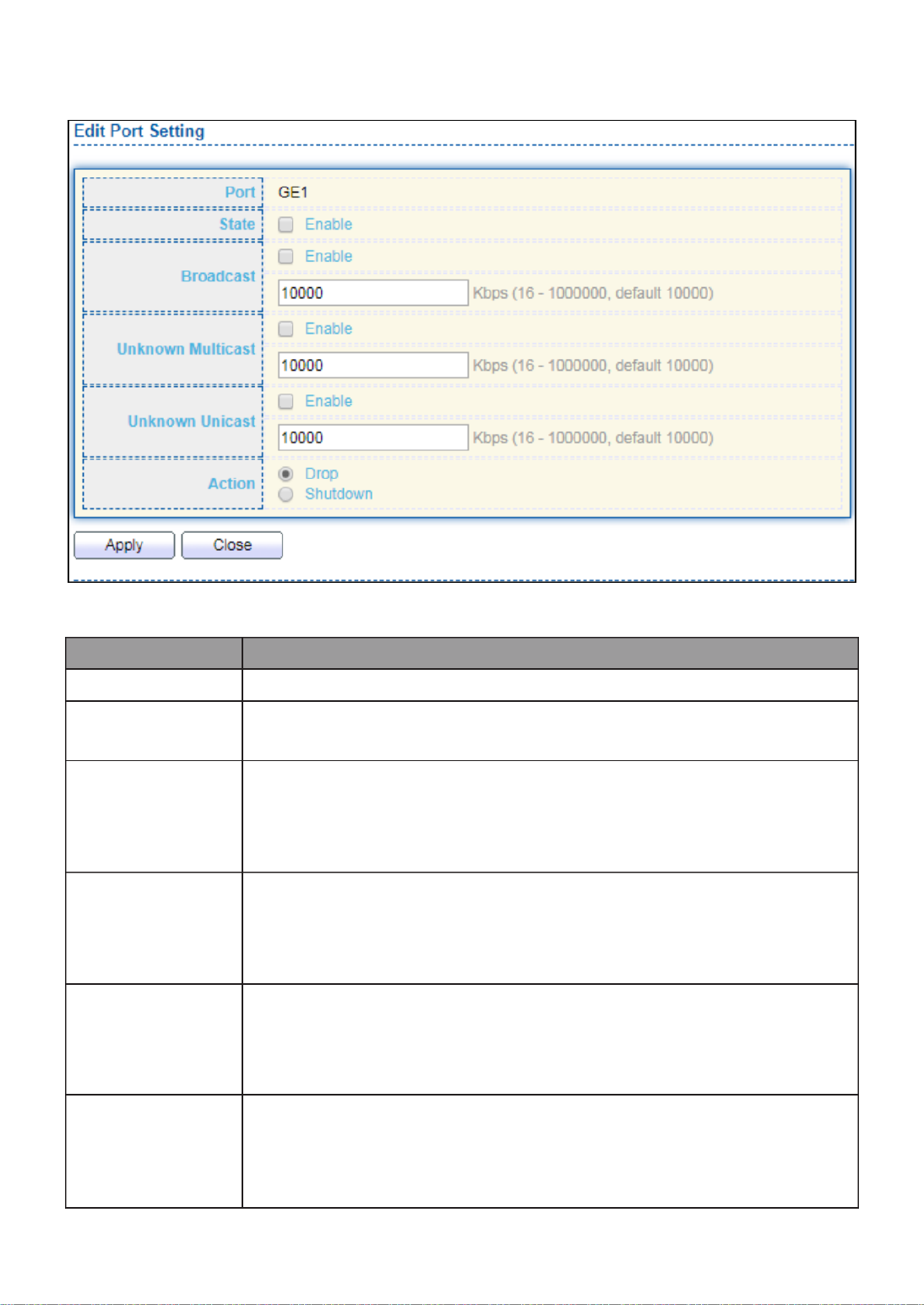
115
Click " " button to view Edit Port Setting menu. Edit
Figure 109 - Security > Storm Control > Edit Port Setting
Item
Description
Port
Select the setting ports.
State
Select the state of setting
Enable: Enable the storm control function.
Broadcast
Enable: Enable the storm control function of Broadcast packet.
Value of storm control rate, Unit: pps (packet per-second, range
1- 262143) or Kbps (Kbits per-second, range16 - 1000000)
depends on global mode setting.
Unknown
Multicast
Enable: Enable the storm control function of Unknown multicast
packet. Value of storm control rate, Unit: pps (packet
per-second, range 1- 262143) or Kbps (Kbits per-second, range16
- 1000000) depends on global mode setting.
Unknown
Unicast
Enable: Enable the storm control function of Unknown unicast
packet. Value of storm control rate, Unit: pps (packet
per-second, range 1 - 262143) or Kbps (Kbits per-second,
range16 - 1000000) depends on global mode setting.
Action
Select the state of setting
Drop: Packets exceed storm control rate will be dropped.
Shutdown: Port will be shutdown when packets exceed
storm control rate.

116
III 10 7.- - DoS
A Denial of Service (DoS) attack is a hacker attempt to make a device unavailable to its
users. DoS attacks saturate the device with external communication requests, so that it
cannot respond to legitimate traffic. These attacks usually lead to a device CPU overload.
The DoS protection feature is a set of predefined rules that protect the network from
malicious attacks. The DoS Security Suite Settings enables activating the security suite.
III 10 1.- -7- Property
To display Dos Global Setting web page, click . Security > Dos > Property

117
Figure 110 - Security > DoS > Property
Item
Description
POD
Avoids ping of death attack.
Land
Drops the packets if the source IP address is equal to the
destination IP address.
UDP Blat
Drops the packets if the UDP source port equals to the UDP
destination port.
TCP Blat
Drops the packages if the TCP source port is equal to the TCP

118
destination port.
DMAC = SMAC
Drops the packets if the destination MAC address is equal to the
source MAC address.
Null Scan
Attach
Drops the packets with NULL scan.
X- Mas
Scan Attack
Drops the packets if the sequence number is zero, and the FIN,
URG and PSH bits are set.
TCP SYN-FIN
Attack
Drops the packets with SYN and FIN bits set.
TCP SYN-RST
Attack
Drops the packets with SYN and RST bits set
ICMP Fragment
Drops the fragmented ICMP packets.
TCP SYN
(SPORT<1024)
Drops SYN packets with sport less than 1024.
TCP Fragment
(Offset = 1)
Drops the TCP fragment packets with offset equals to one.
Ping Max Size
Specify the maximum size of the ICMPv4/ICMPv6 ping packets.
The valid range is from 0 to 65535 bytes, and the default value is
512 bytes.
IPv6 Min
Fragment
Checks the minimum size of IPv6 fragments, and drops the
packets smaller than the minimum size. The valid range is from 0
to 65535 bytes, and default value is 1240 bytes.
Smurf Attack
Avoids smurf attack. The length range of the netmask is from 0 to
323 bytes, and default length is 0 bytes.
III 10 2.- -7- Port Setting
To configure and display the state of DoS protection for interfaces, click Security > DoS >
Port Setting.

120
III 10 1.- -8- Property
This page allow user to configure global and per interface settings of DHCP Snooping.
To display property page, click Security > DHCP Snooping > Property.
Figure 112 - Security > DHCP Snooping > Property
Item
Description

121
State
Set checkbox to enable/disable DHCP Snooping function.
VLAN
Select VLANs in left box then move to right to enable DHCP
Snooping. Or select VLANs in right box then move to left to
disable DHCP Snooping.
Port Setting Table
Port
Display port ID.
Trust
Display enable/disabled trust attribute of interface.
Verify Chaddr
Display enable/disabled chaddr validation attribute of interface.
Rate Limit
Display rate limitation value of interface.
Click " " button to view Edit Port Setting menu. Edit
Figure - Security > DHCP Snooping > Property > Edit Port Setting 113
Item
Description
Port
Display selected port to be edited
Trust
Set checkbox to enable/disabled trust of interface. All DHCP
packet will be forward directly if enable trust. Default is disabled.
Verify Chaddr
Set checkbox to enable or disable chaddr validation of interface.
All DHCP packets will be checked whether client hardware mac
address is same as source mac in Ethernet header if enable chaddr
validation. Default is disabled.
Rate Limit
Input rate limitation of DHCP packets. The unit is pps. 0 means
unlimited. Default is unlimited.

123
III 10 3.- -8- Option82 Property
This page allow user to set string of DHCP option82 remote ID filed. The string will attach
in option82 if option inserted.
To display Option82 Property page, click Security > DHCP Snooping > Option82 Property.
Figure 115 - Security > DHCP Snooping > Option82 Property
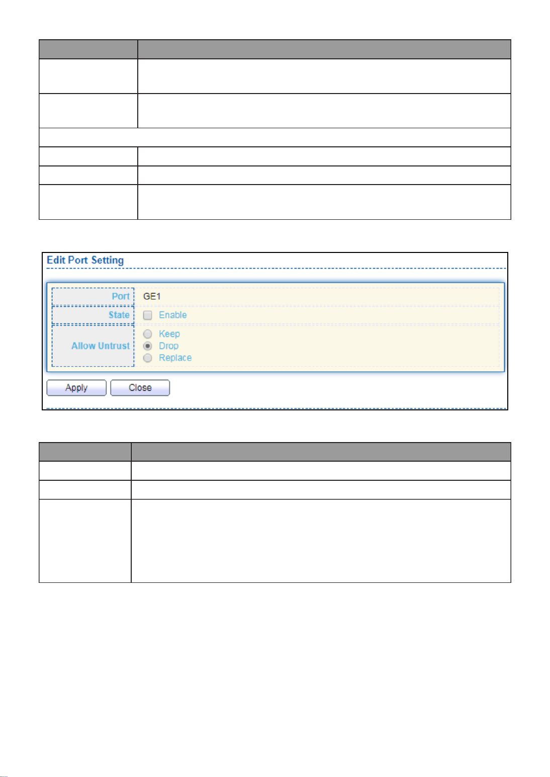
124
Item
Description
User Defined
Set checkbox to enable user-defined remote-ID. By default,
remote ID is switch mac in byte order.
Remote ID
Input user-defined remote ID. Only available when enable
user-define remote ID.
Port Setting Table
Port
Display port ID.
State
Display option82 enable/disable status of interface.
Allow
untrusted
Display allow untrusted action of interface.
Click " " button to view Edit Port Setting menu. Edit
Figure 116 DHCP Snooping > Option82 Property > Edit Port Setting
Item
Description
Port
Display selected port to be edited
State
Set checkbox to enable/disable option82 function of interface.
Allow
untrusted
Select the action perform when untrusted port receive DHCP
packet has option82 filed. Default is drop.
Keep: Keep original option82 content.
Replace: Replace option82 content by switch setting
Drop: Drop packets with option82

125
III 10 4.- -8- Option82 Circuit ID
This page allow user to set string of DHCP option82 circuit ID filed. The string will attach
in option82 if option inserted.
To display Option82 Circuit ID page, click Security > DHCP Snooping > Option82 Circuit
ID.
Figure 117 - Security > DHCP Snooping > Option82 Circuit ID
Item
Description
Port
Display port ID of entry.
VLAN
Display associate VLAN of entry.
Circuit ID
Display circuit ID string of entry.
Click “ ” button or "Add Edit" button to view the Add/Edit Option82 Circuit ID menu.
Figure 118 - Security > DHCP Snooping > Option82 Circuit ID > Add/Edit Option82 Circuit
ID

126
Item
Description
Port
Select port from list to associate to CID entry. Only available on Add
dialog.
VLAN
Input VLAN ID to associate to circuit ID entry. VLAN ID is not
mandatory. Only available on Add dialog.
Circuit ID
Input String as circuit ID. Packets match port and VLAN will be
inserted circuit ID.
III 10 9.- - IP Source Guard
Use the IP Source Guard pages to configure settings of IP Source Guard.
III 10 1.- -9- Port Setting
Use the IP Source Guard pages to configure settings of IP Source Guard.
To display Port Setting page, click Security > IP Source Guard > Port Setting.
Figure 119 - Security > IP Source Guard > Port Setting
Item
Description
Port
Display port ID.
State
Display IP Source Guard enable/disable status of interface.
Verify Source
Display mode of IP Source Guard verification
Current Binding
Entry
Display current binding entries of a interface.
Max Binding
Entry
Display the number of maximum binding entry of interface.
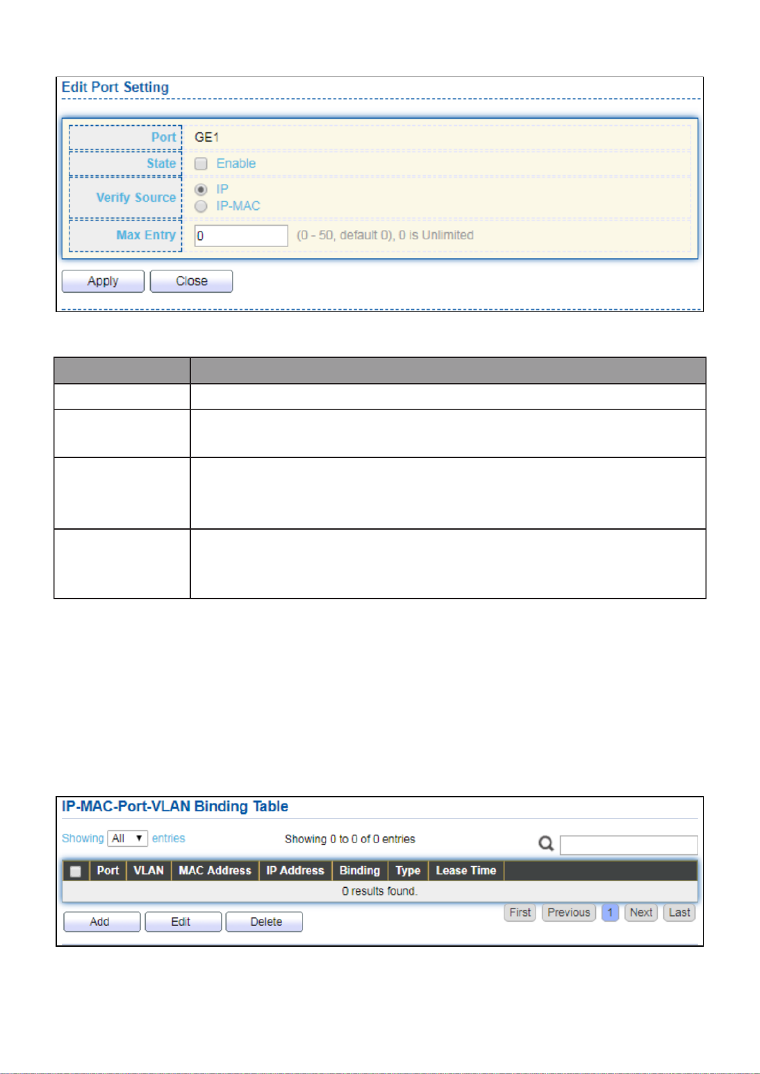
127
Click " " button to view the Edit Port Setting menu. Edit
Figure 120 - Security > IP Source Guard > Port Setting > Edit Port Setting
Item
Description
Port
Display selected port to be edited.
Status
Set checkbox to enable or disable IP Source Guard function.
Default is disabled.
Verify Source
Select the mode of IP Source Guard verification
IP: Only verify source IP address of packet.
IP-MAC: Verify source IP and source MAC address of packet.
Max Entry
Input the maximum number of entries that a port can be
bounded. Default is un-limited on all ports. No entry will be bound
if limitation reached.
III 10 2.- -9- IMPV Binding
This page allow user to add static IP source guard entry and browse all IP source guard
entries that learned by DHCP snooping or statically create by user.
To display IPMV Binding page, click Security > IP Source Guard > IMPV Binding.
Figure 121 - Security > IP Source Guard > IMPV Binding

128
Item
Descripon
Port
Display port ID of entry.
VLAN
Display VLAN ID of entry.
MAC Address
Display MAC address of entry. Only available of IP-MAC binding
entry.
IP Address
Display IP address of entry. Mask always to be 255.255.255.255
for IP-MAC binding. IP binding entry display user input.
Binding
Display binding type of entry.
Type
Type of existing binding entry
Static: Entry added by user.
Dynamic: Entry learned by DHCP snooping.
Lease Time
Lease time of DHCP Snooping learned entry. After lease time
entry will be deleted. Only available of dynamic entry.
Click "Add" or “Edit” buon to view the Add/Edit IP-MAC-Port-VLAN Binding menu.
Figure 122 - Security > IP Source Guard > Add/Edit IP-MAC-Port-VLAN Binding

129
Item
Description
Port
Select port from list of a binding entry.
VLAN
Specify a VLAN ID of a binding entry.
Binding
Select matching mode of binding entry
IP-MAC-Port-VLAN: packet must match IP address MAC 、
address Port and VLAN ID. 、
IP-Port-VLAN: packet must match IP address or subnet Port and 、
VLAN ID.
MAC Address
Input MAC address. Only available on IP-MAC-Port-VLAN mode.
IP Address
Input IP address and mask. Mask only available on IP-MAC-Port
mode.
III 10 3.- -9- Save Database
This page allow user to congure DHCP snooping database which can backup and restore
dynamic DHCP snooping entries.
To display Save Database page, click Security > DHCP Snooping > Save Database.
Figure 123 - Security > IP Source Guard > Save Database
Item
Description
Type
Select the type of database agent.
None: Disable database agent service.
Flash: Save DHCP dynamic binding entries to ash.
TFTP: Save DHCP dynamic binding entries to remote TFTP
server.

130
Filename
Input lename for backup le. Only available when selecng type
“flash” and “TFTP”.
Address Type
Select the type of TFTP server.
Hostname: TFTP server address is hostname.
IPv4: TFTP server address is IPv4 address
Server Address
Input remote TFTP server hostname or IP address. Only available
when selecting type “TFTP”
Write Delay
Input delay mer for doing backup aer change happened.
Default is 300 seconds.
Timeout
Input aborts meout for doing backup failure. Default is 300
seconds.
III 11.- ACL
Use the ACL pages to congure seings for the switch ACL features..
III 11 1.- - MAC ACL
This page allow user to add or delete ACL rule. A rule cannot be deleted if under binding.
To display MAC ACL page, click . ACL > MAC ACL
Figure 124 - ACL > MAC ACL
Item
Description
ACL Name
Input MAC ACL name.
ACL Name
Display MAC ACL name.
Rule
Display the number ACE rule of ACL.
Port
Display the port list that bind this ACL.

131
III 11 2.- - MAC ACE
This page allow user to add, edit or delete ACE rule. An ACE rule cannot be edited or
deleted if ACL under binding. New ACE cannot be added if ACL under binding.
To display MAC ACE page, click ACL > MAC ACE.
Figure 125 - ACL > MAC ACE
Item
Description
ACL Name
Select the ACL name to which an ACE is being added.
Sequence
Display the sequence of ACE.
Action
Display the action of ACE.
Source MAC
Display the source MAC address and mask of ACE.
Destination
MAC
Display the destination MAC address and mask of ACE.
Ethertype
Display the Ethernet frame type of ACE.
VLAN ID
Display the VLAN ID of ACE.
802.1p Value
Display the 802.1p value of ACE.
802.1p Mask
Display the 802.1p mask of ACE.

132
Click “ ” button to view the Edit ACE menu.Edit
Figure 126 - ACL > Edit ACE
Item
Description
ACL Name
Display the ACL name to which an ACE is being added..
Sequence
Specify the sequence of the ACE. ACEs with higher sequence are
processed first (1 is the highest priority). Only available on Add
Dialog.
Action
Select the action after ACE match packet.
Permit: Forward packets that meet the ACE criteria.
Deny: Drop packets that meet the ACE criteria.
Shutdown: Drop packets that meet the ACE criteria, and
disable the port from where the packets were received. Such
ports can be reactivated from the Port Settings page.
Source MAC
Select the type for source MAC address.
Any: All source addresses are acceptable.
User Defined: Only a source address or a range of source
addresses which users define are acceptable. Enter the
source MAC address and mask to which will be matched.

133
Desnaon
MAC
Select the type for Desnaon MAC address.
Any: All desnaon addresses are acceptable.
User Dened: Only a desnaon address or a range of
desnaon addresses which users dene are acceptable.
Enter the desnaon MAC address and mask to which will
be matched.
Ethertype
Select the type for Ethernet frame type.
Any: All Ethernet frame type is acceptable.
User Dened: Only an Ethernet frame type which users
dene is acceptable. Enter the Ethernet frame type value to
which will be matched.
VLAN
Select the type for VLAN ID.
Any: All VLAN ID is acceptable.
User Dened: Only a VLAN ID which users dene is
acceptable. Enter the VLAN ID to which will be matched.
802.1p
Select the type for 802.1p value.
Any: All 802.1p value is acceptable.
User Dened: Only an 802.1p value or a range of 802.1p
value which users dene is acceptable. Enter the 802.1p
value and mask to which will be matched.
III 11 3.- - IPv4 ACL
This page allow user to add or delete IPv4 ACL rule. A rule cannot be deleted if under
binding.
To display IPv4 ACL page, click . ACL > IPv4 ACL
Figure 127 - ACL > IPv4 ACL
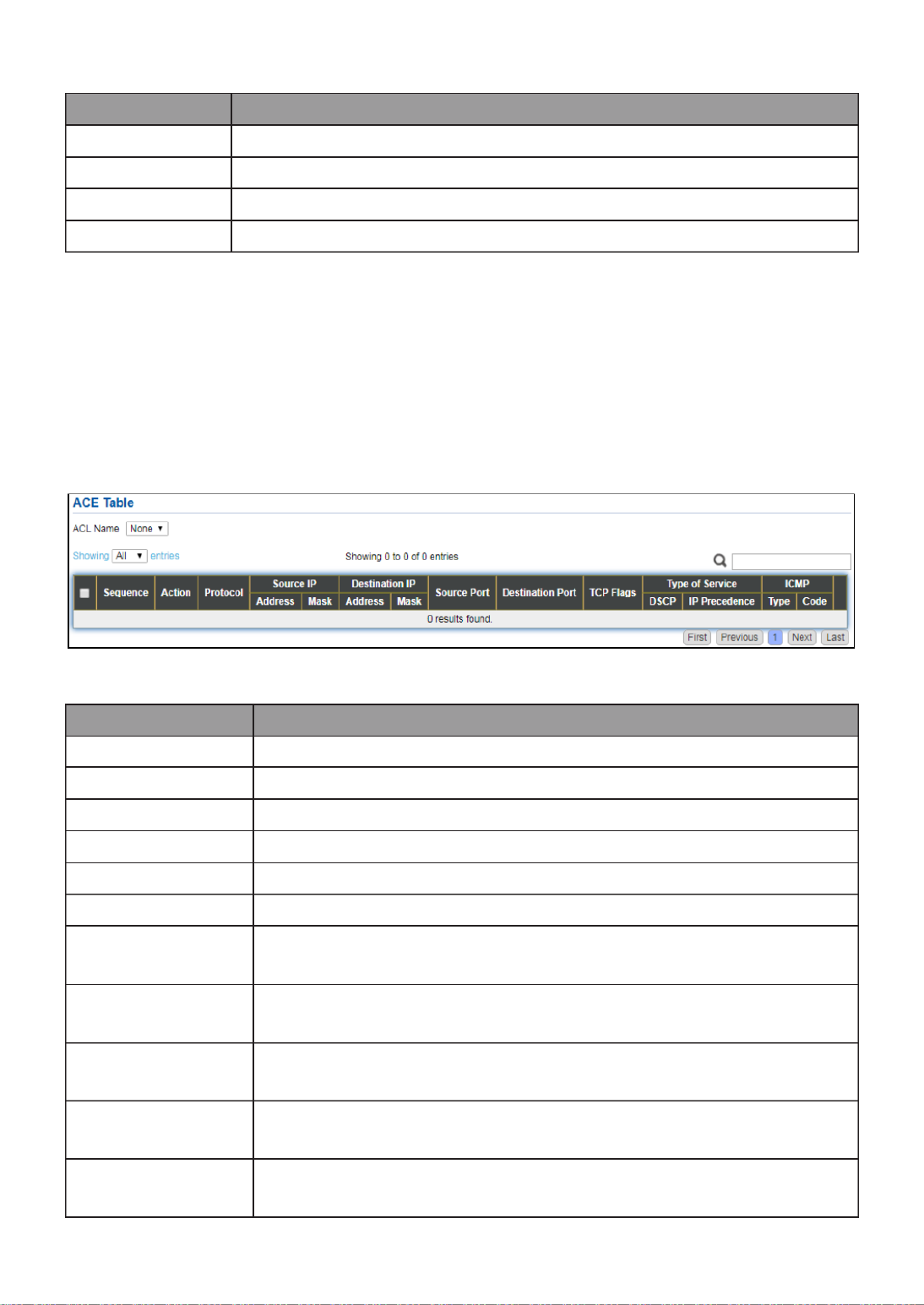
134
Item
Descripon
ACL Name
Input IPv4 ACL name.
ACL Name
Display IPv4 ACL name.
Rule
Display the number ACE rule of ACL.
Port
Display the port list that bind this ACL.
III 11 4.- - IPv4 ACE
This page allow user to add, edit or delete ACE rule. An ACE rule cannot be edited or
deleted if ACL under binding. New ACE cannot be added if ACL under binding.
To display IPv4 ACE page, click . ACL > IPv4 ACE
Figure 128 - ACL > IPv4 ACE
Item
Descripon
ACL Name
Select the ACL name to which an ACE is being added.
Sequence
Display the sequence of ACE.
Acon
Display the acon of ACE.
Protocol
Display the protocol value of ACE.
Source IP
Display the source IP address and mask of ACE.
Desnaon IP
Display the desnaon IP address and mask of ACE.
Source Port
Display single source port or a range of source ports of ACE.
Only available when protocol is TCP or UDP.
Desnaon Port
Display single desnaon port or a range of desnaon ports of
ACE. Only available when protocol is TCP or UDP.
TCP Flags
Display the TCP ag value if ACE. Only available when protocol
is TCP.
Type of Service
Display the ToS value of ACE which could be DSCP or IP
Precedence.
ICMP
Display the ICMP type and code of ACE. Only available when
protocol is ICMP.

135
Click "Add" or “Edit” buon to view the Add/Edit ACE menu.
Figure 129 - ACL > Add/Edit ACE

136
Item Descripon
ACL Name
Display the ACL name to which an ACE is being added.
Sequence
Specify the sequence of the ACE. ACEs with higher sequence are
processed rst (1 is the highest sequence). Only available on Add
dialog.
Acon
Select the acon for a match.
Permit: Forward packets that meet the ACE criteria.
Deny: Drop packets that meet the ACE criteria.
Shutdown: Drop packets that meet the ACE criteria, and disable
the port from where the packets were received. Such ports can
be reacvated from the Port Sengs page.
Protocol
Select the type of protocol for a match.
Any (IP): All IP protocols are acceptable.
Select from list: Select one of the following protocols from the
drop-down list.
ICMP/IPinIP/TCP/EGP/IGP/UDP/HMP/RDP/IPV6/IPV6:ROUT/IPV6:F
RAG/ RSVP/IPV6:ICMP/OSPF/PIM/L2TP
Protocol ID to match: Enter the protocol ID.
Source IP
Select the type for source IP address.
Any: All source addresses are acceptable.
User Dened: Only a source address or a range of source
addresses which users dene are acceptable. Enter the source
IP address value and mask to which will be matched.
Desnaon
IP
Select the type for desnaon IP address.
Any: All desnaon addresses are acceptable.
User Dened: Only a desnaon address or a range of
desnaon addresses which users dene are acceptable. Enter
the desnaon IP address value and mask to which will be
matched.
Source Port
Select the type of protocol for a match. Only available when
protocol is TCP or UDP.
Any: All source ports are acceptable.
Single: Enter a single TCP/UDP source port to which packets are
matched.
Range: Select a range of TCP/UDP source ports to which the
packet is matched. There are eight dierent port ranges that
can be congured (shared between source and desnaon
ports). TCP and UDP protocols each have eight port ranges.
Desnaon
Port
Select the type of protocol for a match. Only available when
protocol is TCP or UDP.
Any: All source ports are acceptable.
Single: Enter a single TCP/UDP source port to which packets are
matched.

137
Range: Select a range of TCP/UDP source ports to which the
packet is matched. There are eight dierent port ranges that
can be congured (shared between source and desnaon
ports). TCP and UDP protocols each have eight port ranges.
TCP Flags
Select one or more TCP ags with which to lter packets. Filtered
packets are either forwarded or dropped. Filtering packets by TCP
ags increases packet control, which increases network security.
Only available when protocol is TCP.
Type of
Servi ce
Select the type of service for a match.
Any: All types of service are acceptable.
DSCP to match: Enter a Dierenated Serves Code Point (DSCP)
to match.
IP Precedence to match: Enter a IP Precedence to match.
ICMP Type
Either select the message type by name or enter the message type
number. Only available when protocol is ICMP.
Any: All message types are acceptable.
Select from list: Select message type by name.
Protocol ID to match: Enter the number of message type.
ICMP Code
Select the type for ICMP code. Only available when protocol is
Any: All codes are acceptable.
User Dened: Enter an ICMP code to match.
III 11 5.- - ACL Binding
This page allow user to bind or unbind ACL rule to or from interface. IPv4 and Ipv6 ACL
cannot be bound to the same port simultaneously.
To display ACL Binding page, click . ACL > ACL Binding
Figure 130 - ACL > ACL Binding

138
Item
Descripon
Port
Display port entry ID.
MAC ACL
Display mac ACL name that bound of interface. Empty means no
rule bound.
IPv4 ACL
Display ipv4 ACL name that bound of interface. Empty means no
rule bound.
IPv6 ACL
Display ipv6 ACL name that bound of interface. Empty means no
rule bound.
Click “ ” buon to Edit view the Edit ACL Binding menu.
Figure 131 - ACL > Edit ACL Binding
Item
Descripon
Port
Display port entry ID.
MAC ACL
Select mac ACL name from list to bind.
IPv4 ACL
Select IPv4 ACL name from list to bind.
IPv6 ACL
Select IPv6 ACL name from list to bind.
III 12.- QoS
Use the QoS pages to congure sengs for the switch QoS interface.
III 12 1.- - General
Use the QoS general pages to congure sengs for general purpose.

139
III 12 1.- -1- Property
To display Property web page, click . QoS > General > Property
Figure 132 - QoS > General > Property
Item
Descripon
State
Set checkbox to enable/disable QoS.
Trust
Select QoS trust mode
CoS: Trac is mapped to queues based on the CoS eld in
the VLAN tag, or based on the per-port default CoS value (if
there is no VLAN tag on the incoming packet), the actual
mapping of the CoS to queue can be congured on port
seng dialog.
CoS-DSCP: Uses the trust CoS mode for non-IP trac and
trust DSCP mode for IP trac.
IP Precedence: Trac is mapped to queues based on the IP
precedence. The actual mapping of the IP precedence to
queue can be congured on the IP Precedence mapping
page.
Port Seng Table
Port
Port name
CoS
Port default CoS priority value for the selected ports.
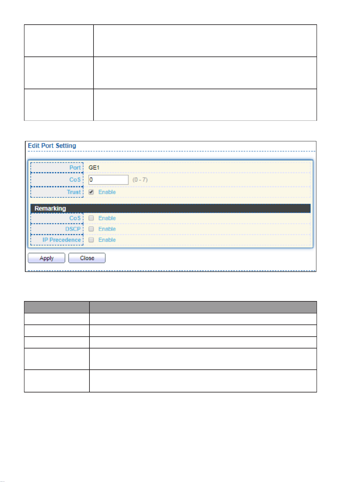
140
Trust
Port trust state
Enabled: Trac will follow trust mode in global seng
Disabled: Trac will always use best eorts
Remarking (CoS)
Set checkbox to enable/disable port CoS remarking.
Enabled: CoS remarking is enabled
Disabled: CoS remarking is disabled
Remarking
(IP Precedence)
Set checkbox to enable/disable port IP Precedence remarking.
Enabled: DSCP remarking is enabled
Disabled: DSCP remarking is disabled
Click " " buon to view the Edit Port Seng menu. Edit
Figure 133 - Qos > General > Property
Item
Descripon
Port
Selected port list.
CoS
Set default CoS/802.1p priority value for the selected ports.
Trust
Set checkbox to enable/disable port trust state.
Remarking
(CoS)
Set checkbox to enable/disable port CoS remarking.
Remarking
(IP Precedence)
Set checkbox to enable/disable port IP Precedence remarking.
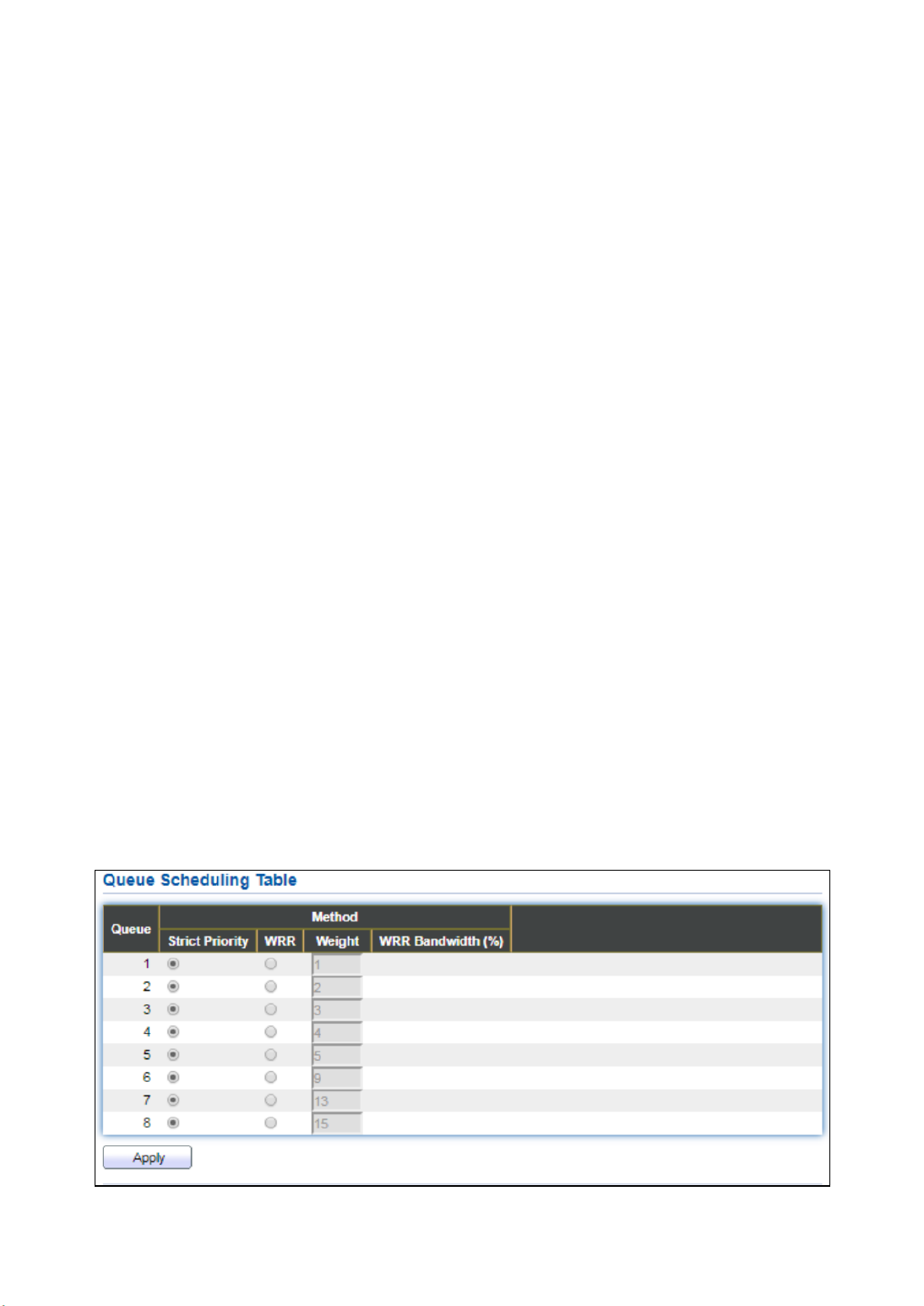
141
III 12 2.- -1- Queue Scheduling
The switch supports eight queues for each interface. Queue number 8 is the highest
priority queue.
Queue number 1 is the lowest priority queue. There are two ways of determining how
trac in queues is handled, Strict Priority (SP) and Weighted Round Robin (WRR).
‧ Strict Priority (SP) Egress trac from the highest priority queue is transmied rst. —
Trac from the lower queues is processed only aer the highest queue has been
transmied, which provide the highest level of priority of trac to the highest numbered
queue.
‧ Weighted Round Robin (WRR) In WRR mode the number of packets sent from the —
queue is proporonal to the weight of the queue (the higher the weight, the more frames
are sent).
The queuing modes can be selected on the Queue page.When the queuing mode is by
Strict Priority, the priority sets the order in which queues are serviced, starng with
queue_8 (the highest priority queue) and going to the next lower queue when each
queue is completed.
When the queuing mode is Weighted Round Robin, queues are serviced unl their quota
has been used up and then another queue is serviced. It is also possible to assign some of
the lower queues to WRR, while keeping some of the higher queues in Strict Priority. In
this case trac for the SP queues is always sent before trac from the WRR queues.
Aer the SP queues have been emped, trac from the WRR queues is forwarded. (The
relave poron from each WRR queue depends on its weight).
To display Queue Scheduling web page, click QoS > General > Queue Scheduling
Figure 134 - QoS > General > Queue Scheduling

142
Item
Descripon
Queue
Queue ID to congure.
Strict Priority
Set queue to strict priority type.
WRR
Set queue to Weight round robin type.
Weight
If the queue type is WRR, set the queue weight for the queue.
WRR
Bandwidth
Percentage of WRR queue bandwidth.
III 12 3.- -1- CoS Mapping
The CoS to Queue table determines the egress queues of the incoming packets based on
the 802.1p priority in their VLAN tags. For incoming untagged packets, the 802.1p priority
will be the default CoS/802.1p priority assigned to the ingress ports. Use the Queues to
CoS table to remark the CoS/802.1p priority for egress trac from each queue.
To display CoS Mapping web page, click QoS > General > CoS Mapping.
Figure 135 - QoS > General > Cos Mapping

143
Item
Descripon
CoS to Queue Mapping
CoS
CoS value.
Queue
Select queue id for the CoS value.
Queue to CoS Mapping
Queue
Queue ID
CoS
Select CoS value for the queue id.
III 12 4.- -1- IP Precedence Mapping
This page allow user to congure IP Precedence to Queue mapping and Queue to IP
Precedence mapping.
To display IP Precedence Mapping web page, click QoS > General > IP Precedence
Mapping.
Figure 136 - QoS > General > IP Precdence Mapping
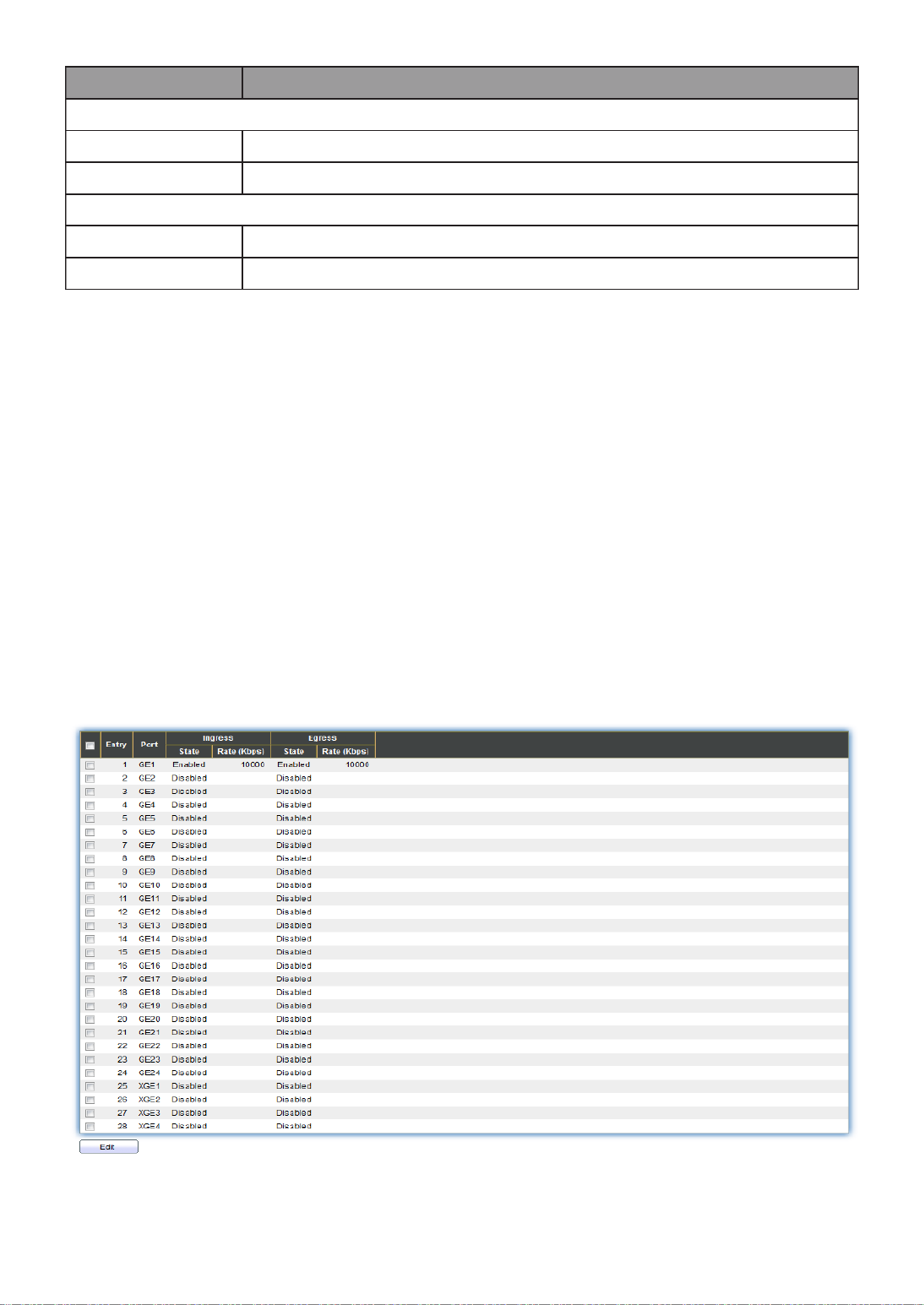
144
Item
Descripon
IP Precedence to Queue Mapping
IP Precedence
IP Precedence value.
Queue
Queue value which IP Precedence is mapped.
Queue to IP Precedence Mapping
Queue
Queue ID.
IP Precedence
IP Precedence value which queue is mapped.
III 12 2.- - Rate Limit
Use the Rate Limit pages to dene values that determine how much trac the switch can
receive and send on specic port or queue.
III 12 1.- -2- Ingress/Egress Port
This page allow user to congure ingress port rate limit and egress port rate limit. The
ingress rate limit is the number of bits per second that can be received from the ingress
interface. Excess bandwidth above this limit is discarded.
To display Ingress / Egress Port web page, click QoS > Rate Limit > Ingress / Egress Port.
Figure 137 - QoS > Rate Limit > Ingress / Egress Port
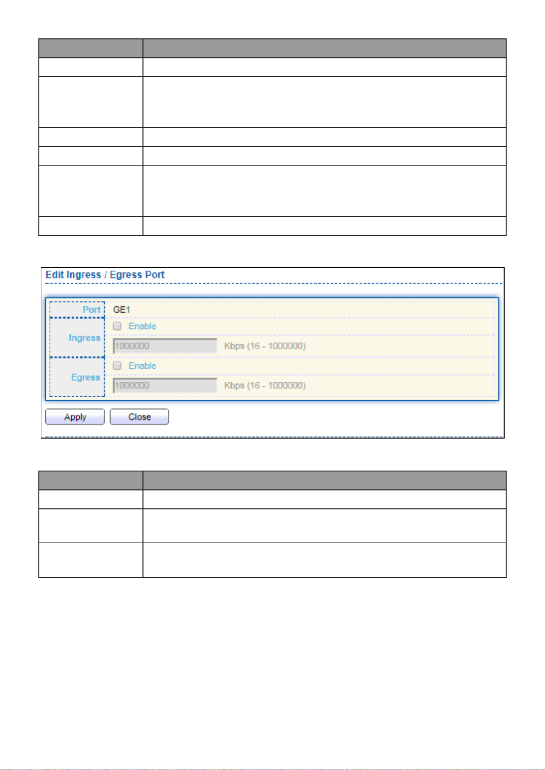
145
Item
Descripon
Port
Port name.
Ingress (State)
Port ingress rate limit state
Enabled: Ingress rate limit is enabled
Disabled: Ingress rate limit is disabled
Ingress (Rate)
Port ingress rate limit value if ingress rate state is enabled.
IP Precedence
IP Precedence value which queue is mapped.
Egress (State)
Port egress rate limit state
Enabled: Egress rate limit is enabled
Disabled: Egress rate limit is disabled
Egress (Rate)
Port egress rate limit value if egress rate state is enabled.
Click " " buon to view the Ingress / Egress Port menu. Edit
Figure 138 - QoS > Rate Limit > Ingress / Egress Port
Item
Descripon
Port
Select port list.
Ingress
Set checkbox to enable/disable ingress rate limit. If ingress rate
limit is enabled, rate limit value need to be assigned.
Egress
Set checkbox to enable/disable egress rate limit. If egress rate
limit is enabled, rate limit value need to be assigned.
III 13.- Diagnoscs
Use the Diagnoscs pages to congure sengs for the switch diagnoscs feature or
operang diagnosc ulies.
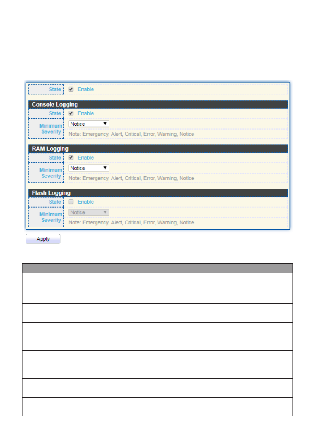
146
III 13 1.- - Logging
III 13 1.- -1- Property
To enable/disable the logging service, click Diagnosc > Logging > Property.
Figure 139 - Diagnoscs > Logging > Property
Item
Descripon
State
Enable/Disable the global logging services. When the logging
service is enabled, logging conguraon of each desnaon rule
can be individually congured. If the logging service is disabled, no
messages will be sent to these desnaons.
Console Logging
State
Enable/Disable the console logging service
Minimum
Severity
The minimum severity for the console logging.
RAM Logging
State
Enable/Disable the RAM logging service.
Minimum
Severity
The minimum severity for the RAM logging.
Flash Logging
State
Enable/Disable the ash logging service.
Minimum
Severity
The minimum severity for the ash loggin.
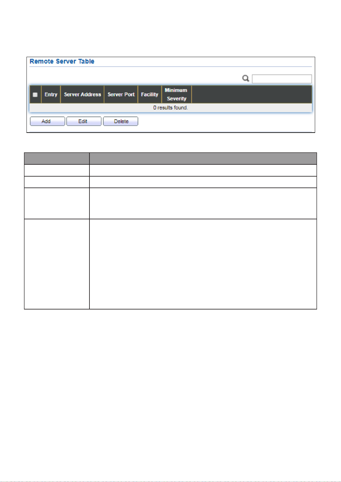
147
III 13 2.- -1- Remote Server
To congure the remote logging server, click Diagnosc > Logging > Remote Server.
Figure 140 - Diagnoscs > Logging > Remote Server
Item
Descripon
Server Address
The IP address of the remote logging server.
Server Ports
The port number of the remote logging server.
Facility
The facility of the logging messages. It can be one of the
following values: local0, local1, local2, local3, local4, local5,
local6, and local7.
Minimum
Severity
Emergence: System is not usable.
Alert: Immediate acon is needed.
Crical: System is in the crical condion.
Error: System is in error condion
Warning: System warning has occurred
Noce: System is funconing properly, but a system noce
has occurred.
Informaonal: Device informaon.
Debug: Provides detailed informaon about an event.

148
III 13 2.- - Mirroring
To display Port Mirroring web page, click Diagnoscs > Mirroring.
Figure 141 - Diagnoscs > Mirroring
Item
Descripon
Session ID
Select mirror session ID.
State
Select mirror session state : port-base mirror or disable
Enabled: Enable port based mirror
Disabled: Disable mirror.
Monitor Port
Select mirror session monitor port, and select whether normal
packet could be sent or received by monitor port.
Ingress port
Select mirror session source rx ports.
Egress port
Select mirror session source tx ports.

149
Click " " buon to view the Edit Mirroring menu. Edit
Figure 142 - Diagnoscs > Mirroring > Edit Mirroring
Item
Descripon
Session ID
Selected mirror session ID.
State
Select mirror session state : port-base mirror or disable
Enabled: Enable port based mirror
Disabled: Disable mirror.
Monitor Port
Select mirror session monitor port, and select whether normal
packet could be sent or received by monitor port.
Ingress port
Select mirror session source rx ports.
Egress port
Select mirror session source tx ports.

150
III 13 3.- - Ping
For the ping funconality, click . Diagnosc > Ping
Figure 143 - Diagnoscs > Ping
Item
Descripon
Address
Type
Specify the address type to “Hostname”or “IPv4”.
Server
Address
Specify the Hostname/IPv4 address for the remote logging server.
Count
Specify the numbers of each ICMP ping request.
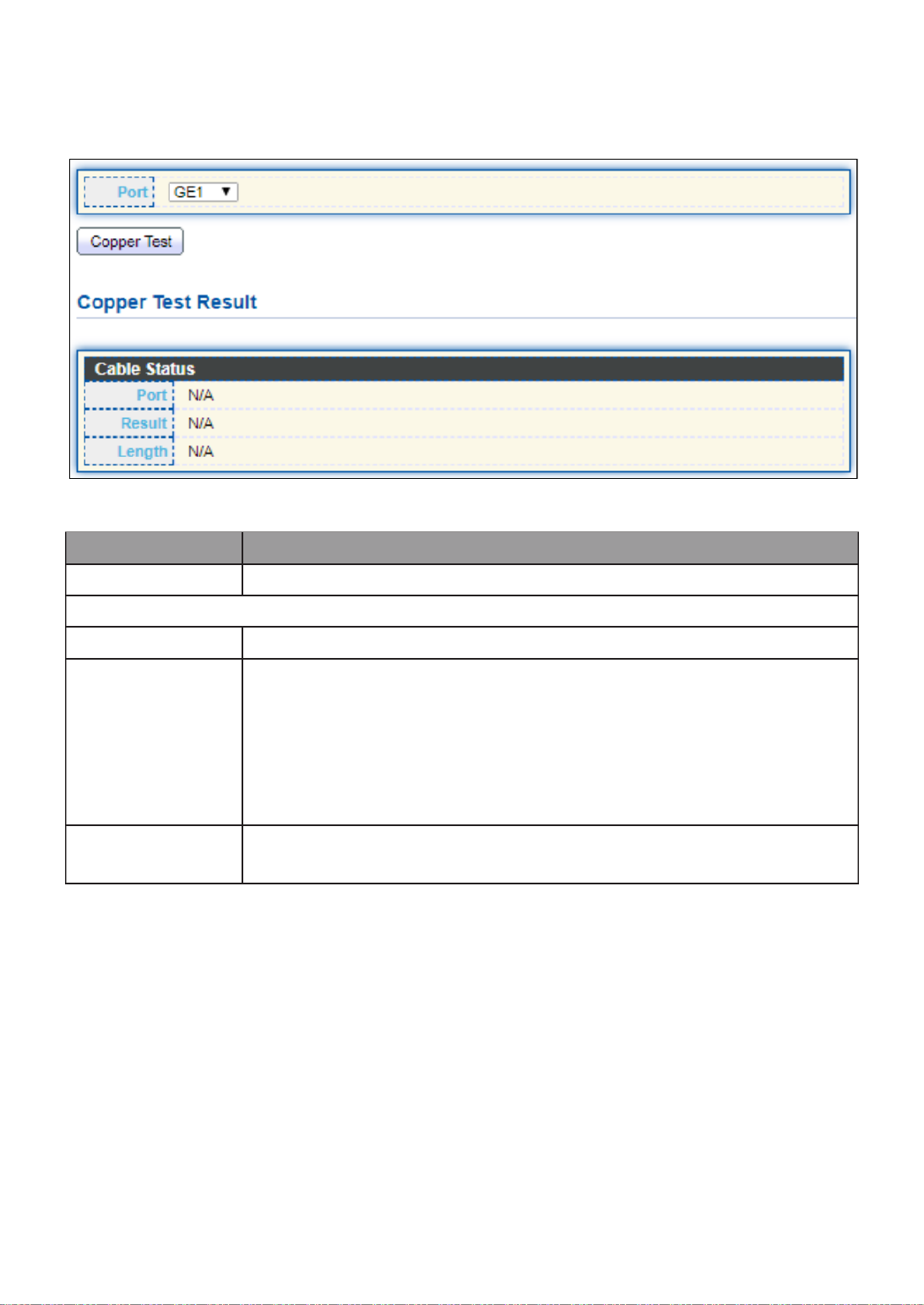
152
III 13 5.- - Copper Test
For copper length diagnosc, click . Diagnosc > Copper Test
Figure 145 - Diagnoscs > Logging>Copper Test
Item
Descripon
Port
Specify the interface for the copper test.
Copper Test Result
Port
The interface for the copper test.
Result
The status of copper test. It include:
OK: Correctly terminated pair.
Short Cable: Shorted pair.
Open Cable: Open pair, no link partner.
Impedance Mismatch: Terminang impedance is not in the
reference range.
Length
Distance in meter from the port to the locaon on the cable
where the fault was discovered.

154
Click " " buon to view the Fiber Module Status menu Detail
Figure 147 - Diagnoscs > Logging>Fiber Module>Fiber Module Status
III 13 7.- - UDLD
Use the UDLD pages to congure seings of UDLD funcon.
III 13 1.- -7- Property
This page allow user to congure global and per interface sengs of UDLD.

155
To display Property page, click Diagnoscs > UDLD > Property.
Figure 148 - Diagnoscs > UDLD>Property
Item
Descripon
Message Time
Input the interval for sending message. Range is 1 -90 seconds.
Port
Display port ID of entry.
Mode
Display UDLD running mode of interface.
Bidireconal
State
Display bidireconal state of interface.
Operaonal
Status
Display operaonal status of interface.
Neighbor
Display the number of neighbor of interface.
Click " " buon to view the Fiber Module Status menu Edit
Figure 149 - Diagnoscs > UDLD>Property>Edit
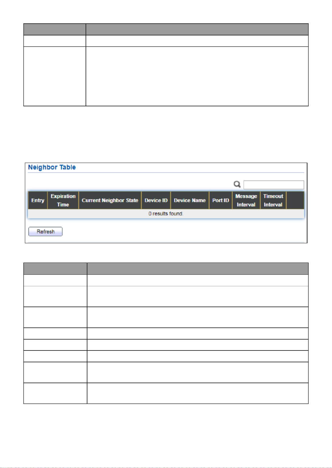
156
Item
Descripon
Port
Display selected port to be edited.
Mode
Select UDLD running mode of interface.
Disabled: Disable UDLD funcon.
Normal: Running on normal mode that port goes to Link Up
One phase aer last neighbor ages out.
Aggressive: Running on aggressive mode that port goes to
Re-Establish phase aer last neighbor ages out.
III 13 2.- -7- Neighbor
To display Neighbor page, click Diagnoscs > UDLD > Neighbor
Figure 150 - Diagnoscs > UDLD> Neighbor
Item
Descripon
Entry
Display entry index.
Expiraon
Time
Display expiraon me before age out.
Current
Neighbor State
Display neighbor current state.
Device ID
Display neighbor device ID.
Device Name
Display neighbor device name.
Port ID
Display neighbor port ID that connected.
Message
Interval
Display neighbor message interval.
Timeout
Interval
Display neighbor meout interval.
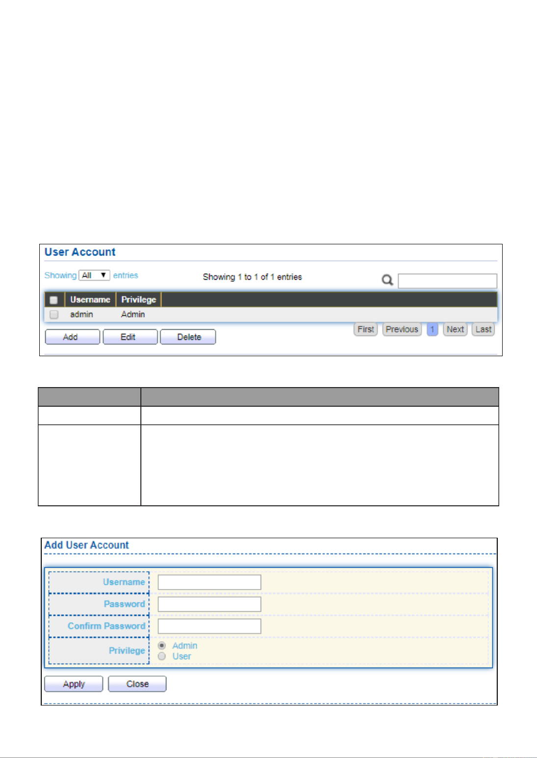
157
III 14.- Management
Use the Management pages to congure sengs for the switch management features.
III 14 1.- - User Account
The default username/password is admin/admin. And default account is not able to be
deleted.
Use this page to add addional users that are permied to manage the switch or to
change the passwords of existing users.
To display User Account web page, click . Management > User Account
Figure 151 - nagement > User Account Ma
Item
Descripon
Username
User name of the account.
Privilege
Select privilege level for new account.
Admin: Allow to change switch sengs. Privilege value
equals to 15.
User: See switch sengs only. Not allow to change it.
Privilege level equals to 1.
Click " " Add or “Edit” buon to view the Add/Edit User Account menu.

158
Figure 152 - Management > User Account > Add/Edit User Account
Item
Descripon
Username
User name of the account.
Password
Set password of the account.
Conrm
Password
Set the same password of the account as in “Password” eld.
Privilege
Select privilege level for new account.
Admin: Allow to change switch sengs. Privilege value
equals to 15.
User: See switch sengs only. Not allow to change it.
Privilege level equals to 1.

159
III 14 2.- - Fireware
III 14 1.- -2- Upgrade / Backup
This page allow user to upgrade or backup rmware image through HTTP or TFTP server.
To display rmware upgrade or backup web page, click Management > Firmware >
Upgrade/Backup.
Figure 153 - Management > Fireware > Upgrate/Backup
Item
Descripon
Acon
Firmware operaons
Upgrade: Upgrade rmware from remote host to DUT.
Backup: Backup rmware image from DUT to remote host.
Method
Firmware upgrade / backup method.
TFTP: Using TFTP to upgrade/backup rmware.
HTTP: Using WEB browser to upgrade/backup rmware.
Filename
Use browser to upgrade rmware, you should select rmware
image le on your host PC.

160
To display rmware upgrade or backup web page, click Management > Firmware >
Upgrade/Backup.
Figure 154 - Management > Fireware > Upgrate/Backup
Item
Descripon
Acon
Firmware operaons
Upgrade: Upgrade rmware from remote host to DUT
Backup: Backup rmware image from DUT to remote host
Method
Firmware upgrade / backup method
TFTP: Using TFTP to upgrade/backup rmware.
HTTP: Using WEB browser to upgrade/backup rmware.
Address Type
Specify TFTP server address type
Hostname: Use domain name as server address
IPv4: Use IPv4 as server address
IPv6: Use IPv6 as server address
Server
Address
Specify TFTP server address.
Filename
Firmware image le name on remote TFTP server

161
To display rmware upgrade or backup web page, click Management > Firmware >
Upgrade/Backup.
Figure 155 - Management > Fireware > Upgrate/Backup
Item
Descripon
Acon
Firmware operaons
Upgrade: Upgrade rmware from remote host to DUT
Backup: Backup rmware image from DUT to remote host
Method
Firmware upgrade / backup method
TFTP: Using TFTP to upgrade/backup rmware.
HTTP: Using WEB browser to upgrade/backup rmware.
Firmware
Firmware paron need to backup
Image0: Firmware image in ash paron 0
Image1: Firmware image in ash paron 1
To display the Fireware Upgrate/Backup web page, click Management > Fireware >
Upgrate/Backup.
Figure 156 - Management > Fireware >Upgrate/Backup

162
Item
Descripon
Acon
Firmware operaons
Upgrade: Upgrade rmware from remote host to DUT
Backup: Backup rmware image from DUT to remote host
Method
Firmware upgrade / backup method
TFTP: Using TFTP to upgrade/backup rmware.
HTTP: Using WEB browser to upgrade/backup rmware.
Firmware
Firmware paron need to backup
Image0: Firmware image in ash paron 0.
Image1: Firmware image in ash paron 1.
Address Type
Specify TFTP server address type
Hostname: Use domain name as server address.
IPv4: Use IPv4 as server address.
IPv6: Use IPv6 as server address.
Server
Address
Specify TFTP server address address.
Filename
File name saved on remote TFTP server.

163
III 14 2.- -2- Acve Image
This page allow user to select rmware image on next boong and show rmware
informaon on both ash parons.
To display the Acve Image web page, click Management > Firmware > Acve Image.
Figure 157 - Management > Fireware > Acve Image
Item
Descripon
Acve Image
Select rmware image to use on next boong
Firmware
Firmware ash paron name.
Version
Firmware version.
Name
Firmware name.
Size
Firmware image size.
Created
Firmware image created date.
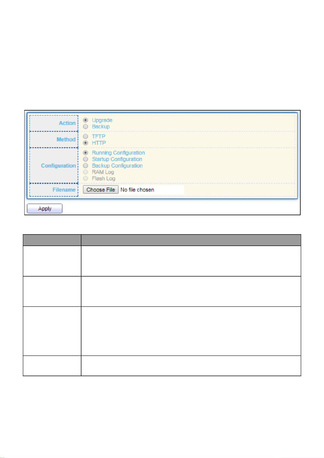
164
III 14 3.- - Conguraon
III 14 1.- -3- Upgrade / Backup
This page allow user to upgrade or backup conguraon le through HTTP or TFTP server.
To display rmware upgrade or backup web page, click Management > Conguraon >
Upgrade/Backup.
Figure 158 - Management > Conguraon > Upgrade/Backup
Item
Descripon
Acon
Conguraon operaons
Upgrade: Upgrade rmware from remote host to DUT
Backup: Backup rmware image from DUT to remote host
Method
Conguraon upgrade / backup method
TFTP: Using TFTP to upgrade/backup rmware
HTTP: Using WEB browser to upgrade/backup rmware
Conguraon
Conguraon types
Running Conguraon: Merge to current running
conguraon le
Startup Conguraon: Replace startup conguraon le
Backup Conguraon: Replace backup conguraon le
Filename
Use browser to upgrade conguraon, you should select
conguraon le on your host PC.
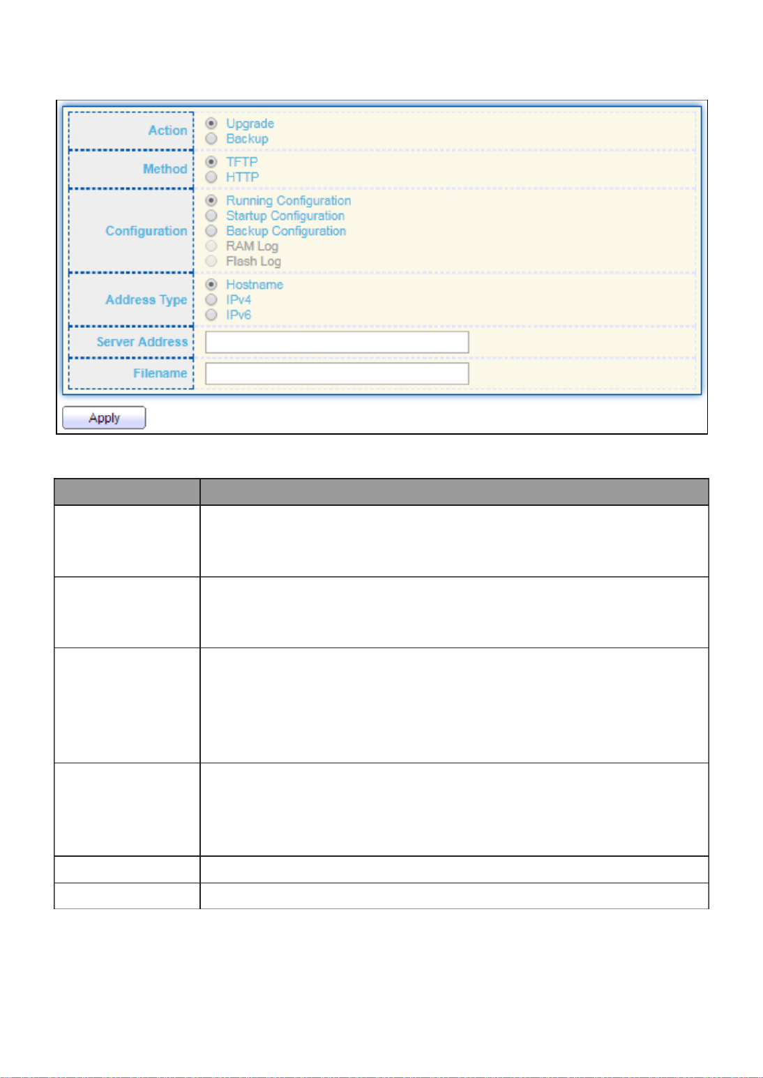
165
To display rmware upgrade or backup web page, click Management > Conguraon >
Upgrade/Backup.
Figure 159 - Management > Conguraon > Upgrade/Backup
Item
Descripon
Acon
Conguraon operaons
Upgrade: Upgrade rmware from remote host to DUT
Backup: Backup rmware image from DUT to remote host
Method
Conguraon upgrade / backup method
TFTP: Using TFTP to upgrade/backup rmware
HTTP: Using WEB browser to upgrade/backup rmware
Conguraon
Conguraon types
Running Conguraon: Merge to current running
conguraon le
Startup Conguraon: Replace startup conguraon le
Backup Conguraon: Replace backup conguraon le
Address Type
Specify TFTP server address type
Hostname: Use domain name as server address
IPv4: Use IPv4 as server address
IPv6: Use IPv6 as server address
Server Address
Specify TFTP server address address
Filename
File name saved on remote TFTP server

166
To display firmware upgrade or backup web page, click Management > Configuration >
Upgrade/Backup.
Figure 160 - Management > Configuration > Upgrade/Backup
Item
Description
Action
Configuration operations
Upgrade: Upgrade firmware from remote host to DUT
Backup: Backup firmware image from DUT to remote host
Method
Configuration upgrade / backup method
TFTP: Using TFTP to upgrade/backup firmware
HTTP: Using WEB browser to upgrade/backup firmware
Configuration
Configuration types
Running Configuration: Backup running configuration file.
Startup Configuration: Backup start configuration file.
Backup Configuration: Backup backup configuration file.
RAM Log: Backup log file stored in RAM.
Flash Log: Backup log files store in Flash.

167
To display firmware upgrade or backup web page, click Management > Configuration >
Upgrade/Backup
Figure 161- Management > Configuration > Upgrade/Backup
Item
Description
Action
Configuration operations
Upgrade: Upgrade firmware from remote host to DUT
Backup: Backup firmware image from DUT to remote host
Method
Configuration upgrade / backup method
TFTP: Using TFTP to upgrade/backup firmware
HTTP: Using WEB browser to upgrade/backup firmware
Configuration
Configuration types
Running Configuration: Backup running configuration file.
Startup Configuration: Backup start configuration file.
Backup Configuration: Backup backup configuration file.
RAM Log: Backup log file stored in RAM.
Flash Log: Backup log files store in Flash.
Address Type
Specify TFTP server address type
Hostname: Use domain name as server address
IPv4: Use IPv4 as server address
IPv6: Use IPv6 as server address
Server Address
Specify TFTP server address address.
Filename
File name saved on remote TFTP server.

169
Item Description
View
The SNMP view name. Its maximum length is 30 characters
OID Subtree
Specify the ASN.1 subtree object identifier (OID) to be included
or excluded from the SNMP view
Type
Include or exclude the selected MIBs in the view
III 14 2.- -4- Group
To configure and display the SNMP group settings, click Management > SNMP > Group.
Figure 164 - Management > SNMP > Group
Item
Description
Group
Specify SNMP group name, and the maximum length is 30
characters.
Version
Specify SNMP version
SNMPv1: SNMP Version 1.
SNMPv2: Community-based SNMP Version 2.
SNMPv3: User security model SNMP version 3.
Security Level
Specify SNMP security level
No Security: Specify that no packet authentication is
performed.
Authentication: Specify that no packet authentication without
encryption is performed.
Authentication and Privacy: Specify that no packet
authentication with encryption is performed.
View
Read
Group read view name.
Write
Group write view name.
Notify
The view name that sends only traps with contents that is
included in SNMP view selected for notification.

170
Click " " Add or “Edit” button to view the Add/Edit Group menu.
Figure 165 - Management > SNMP > Group > Add/Edit Group

171
Item Description
Group
Specify SNMP group name, and the maximum length is 30 characters.
Version
Specify SNMP version
SNMPv1: SNMP Version 1.
SNMPv2: Community-based SNMP Version 2.
SNMPv3: User security model SNMP version 3.
Security Level
Specify SNMP security level
No Security : Specify that no packet authentication is performed.
Authentication: Specify that no packet authentication without
encryption is performed.
Authentication and Privacy: Specify that no packet authentication
with encryption is performed.
View
Read
Select read view name if Read is checked.
Write
Select write view name, if Write is checked.
Notify
Select notify view name, if Notify is checked.
III 14 3.- -4- Community
To configure and display the SNMP community settings, click Management > SNMP >
Community.
Figure - Management > SNMP > Community 166
Item
Description
Community
The SNMP community name. Its maximum length is 20 characters.
Group
Specify the SNMP group configured by the command snmp group to
define the object available to the community.
View
Specify the SNMP view to define the object available to the
community.
Access
SNMP access mode
Read-Only: Read only.
Read-Write: Read and write.

172
Click "Add" or “Edit” button to view the Add/Edit Community menu.
Figure 167 - Management > SNMP > Group > Add/Edit Community
Item
Description
Community
The SNMP community name. Its maximum length is 20 characters.
Type
SNMP Community mode
Basic: SNMP community specifies view and access right.
Advanced: SNMP community specifies group.
View
Specify the SNMP view to define the object available to the
community.
Access
SNMP access mode
Read-Only: Read only.
Read-Write: Read and write.
Group
Specify the SNMP group configured by the command snmp group
to define the object available to the community.

173
III 14 4.- -4- User
To configure and display the SNMP users, click Management > SNMP > User.
Figure 168 - Management > SNMP > User
Item
Description
User
Specify the SNMP user name on the host that connects to the
SNMP agent. The max character is 30 characters. For the SNMP v1
or v2c, the user name must match the community name.
Group
Specify the SNMP group to which the SNMP user belongs.
Security Level
SNMP privilege mode
No Security: Specify that no packet authentication is
performed.
Authentication: Specify that no packet authentication
without encryption is performed.
Authentication and Privacy: Specify that no packet
authentication with encryption is performed.
Authentication
Method
Authentication Protocol which is available when Privilege Mode is
Authentication or Authentication and Privacy.
None: No authentication required.
MD5: Specify the HMAC- -96 authentication protocol. MD5
SHA: Specify the HMAC-SHA-96 authentication protocol
Privacy
Method
Encryption Protocol
None: No privacy required.
DES: DES algorithm
Termékspecifikációk
| Márka: | Edimax |
| Kategória: | kapcsoló |
| Modell: | GS-5216PLC |
Szüksége van segítségre?
Ha segítségre van szüksége Edimax GS-5216PLC, tegyen fel kérdést alább, és más felhasználók válaszolnak Önnek
Útmutatók kapcsoló Edimax

5 Október 2024
27 Szeptember 2024
28 Augusztus 2024
20 Augusztus 2024
4 Augusztus 2024
3 Augusztus 2024
2 Augusztus 2024
1 Augusztus 2024
31 Július 2024
30 Július 2024
Útmutatók kapcsoló
- kapcsoló Yamaha
- kapcsoló Nedis
- kapcsoló Worx
- kapcsoló Philips
- kapcsoló SilverCrest
- kapcsoló Bosch
- kapcsoló Theben
- kapcsoló Panasonic
- kapcsoló Doepke
- kapcsoló StarTech.com
- kapcsoló HP
- kapcsoló Ubiquiti Networks
- kapcsoló SunBriteTV
- kapcsoló TP-Link
- kapcsoló Emos
- kapcsoló Vimar
- kapcsoló LogiLink
- kapcsoló Alcatel
- kapcsoló Digitus
- kapcsoló TRENDnet
- kapcsoló Mercusys
- kapcsoló Boss
- kapcsoló Crestron
- kapcsoló Lancom
- kapcsoló ORNO
- kapcsoló Tripp Lite
- kapcsoló Suevia
- kapcsoló Hikvision
- kapcsoló Vivanco
- kapcsoló Netgear
- kapcsoló Asus
- kapcsoló Jabra
- kapcsoló Hama
- kapcsoló Renkforce
- kapcsoló Iogear
- kapcsoló Mercury
- kapcsoló Mikrotik
- kapcsoló Alpine
- kapcsoló Omnitronic
- kapcsoló Toolcraft
- kapcsoló ZyXEL
- kapcsoló Dahua Technology
- kapcsoló Smart-AVI
- kapcsoló Fibaro
- kapcsoló IPGARD
- kapcsoló Planet
- kapcsoló Ernitec
- kapcsoló Tenda
- kapcsoló Black Box
- kapcsoló Tesla
- kapcsoló Eberle
- kapcsoló Extech
- kapcsoló Gembird
- kapcsoló Cisco
- kapcsoló ATen
- kapcsoló SPC
- kapcsoló Unify
- kapcsoló Behringer
- kapcsoló Nexa
- kapcsoló Powerfix
- kapcsoló BaseTech
- kapcsoló APC
- kapcsoló CyberPower
- kapcsoló Ei Electronics
- kapcsoló Fantini Cosmi
- kapcsoló Electro Harmonix
- kapcsoló PreSonus
- kapcsoló Intertechno
- kapcsoló Manhattan
- kapcsoló Plantronics
- kapcsoló Alecto
- kapcsoló Honeywell
- kapcsoló EnGenius
- kapcsoló Adder
- kapcsoló Velleman
- kapcsoló Grandstream
- kapcsoló D-Link
- kapcsoló Blustream
- kapcsoló Monacor
- kapcsoló Shimano
- kapcsoló Epiphan
- kapcsoló One For All
- kapcsoló Trotec
- kapcsoló Chacon
- kapcsoló Elro
- kapcsoló Delta Dore
- kapcsoló Abus
- kapcsoló GAO
- kapcsoló Tiptel
- kapcsoló Finder
- kapcsoló Konig
- kapcsoló Marmitek
- kapcsoló Pyle
- kapcsoló Emerson
- kapcsoló Kemo
- kapcsoló IFM
- kapcsoló DataVideo
- kapcsoló Atlona
- kapcsoló Schneider
- kapcsoló Lindy
- kapcsoló Cudy
- kapcsoló QNAP
- kapcsoló Vemer
- kapcsoló Kaiser
- kapcsoló Grässlin
- kapcsoló Dormakaba
- kapcsoló Cotech
- kapcsoló Audac
- kapcsoló Siig
- kapcsoló Eaton
- kapcsoló Gefen
- kapcsoló Kathrein
- kapcsoló Homematic IP
- kapcsoló Elation
- kapcsoló Provision-ISR
- kapcsoló Vacmaster
- kapcsoló Brilliant
- kapcsoló Rex
- kapcsoló Equip
- kapcsoló H-Tronic
- kapcsoló Victron Energy
- kapcsoló PCE
- kapcsoló IVT
- kapcsoló Vivolink
- kapcsoló Linksys
- kapcsoló Intelix
- kapcsoló Heitronic
- kapcsoló Alfatron
- kapcsoló Smartwares
- kapcsoló Kopp
- kapcsoló CSL
- kapcsoló Speaka
- kapcsoló Belkin
- kapcsoló RGBlink
- kapcsoló KanexPro
- kapcsoló Kramer
- kapcsoló BZBGear
- kapcsoló Generac
- kapcsoló Ansmann
- kapcsoló Intermatic
- kapcsoló Flamingo
- kapcsoló Brennenstuhl
- kapcsoló Eminent
- kapcsoló KlikaanKlikuit
- kapcsoló Elektrobock
- kapcsoló Sylvania
- kapcsoló Tork
- kapcsoló Techly
- kapcsoló Sonance
- kapcsoló Totolink
- kapcsoló Profile
- kapcsoló Matrox
- kapcsoló Steren
- kapcsoló Perel
- kapcsoló AV:link
- kapcsoló Buffalo
- kapcsoló Audiovox
- kapcsoló LevelOne
- kapcsoló Merten
- kapcsoló Goobay
- kapcsoló Hager
- kapcsoló Sygonix
- kapcsoló Clas Ohlson
- kapcsoló EVE
- kapcsoló UPM
- kapcsoló DoorBird
- kapcsoló Gira
- kapcsoló Jung
- kapcsoló WHALE
- kapcsoló PAC
- kapcsoló Wentronic
- kapcsoló Wago
- kapcsoló Monoprice
- kapcsoló OSD Audio
- kapcsoló Berker
- kapcsoló Aeon Labs
- kapcsoló Advantech
- kapcsoló Merlin Gerin
- kapcsoló Micro Connect
- kapcsoló Extron
- kapcsoló Avocent
- kapcsoló Shelly
- kapcsoló Intellinet
- kapcsoló Ebode
- kapcsoló Robbe
- kapcsoló ICasa
- kapcsoló B-tech
- kapcsoló Legrand
- kapcsoló Kraus & Naimer
- kapcsoló Noble
- kapcsoló Ecler
- kapcsoló Inverto
- kapcsoló Triax
- kapcsoló Rule
- kapcsoló CYP
- kapcsoló Phoenix Contact
- kapcsoló Seuthe
- kapcsoló Maclean Energy
- kapcsoló SmartAVI
- kapcsoló DEHN
- kapcsoló SEC24
- kapcsoló Cooking Performance Group
- kapcsoló Adviti
- kapcsoló Flic
- kapcsoló IB Connect
- kapcsoló Liberty
- kapcsoló PureTools
- kapcsoló Hamlet
- kapcsoló Paladin
- kapcsoló Noark
- kapcsoló Cambium Networks
- kapcsoló 2USB
- kapcsoló Roline
- kapcsoló KVM-TEC
- kapcsoló STI
- kapcsoló Ebara
- kapcsoló Mach Power
- kapcsoló Axing
- kapcsoló ConnectPro
- kapcsoló Atlantis Land
- kapcsoló GEV
- kapcsoló Pizzato Elettrica
- kapcsoló Baco
- kapcsoló SEADA
- kapcsoló Comet
- kapcsoló Setti+
- kapcsoló PureLink
- kapcsoló INOGENI
- kapcsoló Luxul
Legújabb útmutatók kapcsoló
9 Április 2025
9 Április 2025
5 Április 2025
5 Április 2025
5 Április 2025
5 Április 2025
3 Április 2025
3 Április 2025
2 Április 2025
2 Április 2025