Használati útmutató ECS VX900-I
Olvassa el alább 📖 a magyar nyelvű használati útmutatót ECS VX900-I (52 oldal) a alaplap kategóriában. Ezt az útmutatót 4 ember találta hasznosnak és 2 felhasználó értékelte átlagosan 4.5 csillagra
Oldal 1/52

VX900-I USER MANUAL
Preface
Copyright
This publication, including all photographs, illustrations and software, is protected
under international copyright laws, with all rights reserved. Neither this manual, nor
any of the material contained herein, may be reproduced without written consent of
the author.
Version 1.0
Disclaimer
The information in this document is subject to change without notice. The manufac-
turer makes no representations or warranties with respect to the contents hereof
and specifically disclaims any implied warranties of merchantability or fitness for
any particular purpose. The manufacturer reserves the right to revise this publica-
tion and to make changes from time to time in the content hereof without obligation
of the manufacturer to notify any person of such revision or changes.
Trademark Recognition
Microsoft, Windows and Windows 7 are registered trademarks of Microsoft Corp.
VIA® are registered trademarks of VIA Corporation.
Other product names used in this manual are the properties of their respective owners
and are acknowledged.
Federal Communications Commission (FCC)
This equipment has been tested and found to comply with the limits for a Class B
digital device, pursuant to Part 15 of the FCC Rules. These limits are designed to
provide reasonable protection against harmful interference in a residential instal-
lation. This equipment generates, uses, and can radiate radio frequency energy and,
if not installed and used in accordance with the instructions, may cause harmful
interference to radio communications. However, there is no guarantee that interfer-
ence will not occur in a particular installation. If this equipment does cause harmful
interference to radio or television reception, which can be determined by turning
the equipment off and on, the user is encouraged to try to correct the interference by
one or more of the following measures:
•Reorient or relocate the receiving antenna
•Increase the separation between the equipment and the receiver
•Connect the equipment onto an outlet on a circuit different from that to
which the receiver is connected
•Consult the dealer or an experienced radio/TV technician for help
Shielded interconnect cables and a shielded AC power cable must be employed with
this equipment to ensure compliance with the pertinent RF emission limits govern-
ing this device. Changes or modifications not expressly approved by the system’s
manufacturer could void the user’s authority to operate the equipment.

ii
VX900-I USER MANUAL
Declaration of Conformity
This device complies with part 15 of the FCC rules. Operation is subject to the follow-
ing conditions:
•This device may not cause harmful interference.
•This device must accept any interference received, including interference
that may cause undesired operation.
Canadian Department of Communications
This class B digital apparatus meets all requirements of the Canadian Interference-
causing Equipment Regulations.
Cet appareil numérique de la classe B respecte toutes les exigences du Réglement
sur le matériel brouilieur du Canada.
The manual consists of the following:
Describes features of the
motherboard.
Hpage 1
Describes installation of
motherboard components.
Hpage 7
Hpage 23
Hpage 41
Installing the Motherboard
Introducing the Motherboard
Provides information on us-
ing the BIOS Setup Utility.
Describes the motherboard
software.
Limits and methods of mesurement of radio disturbance char-
acteristics of information technology equipment
EN 55022
EN 61000-3-2 Disturbances in supply systems caused
EN 61000-3-3 Disturbances in supply systems caused by household appli-
ances and similar electrical equipment “ Voltage fluctuations”
EN 55024 Information technology equipment-Immunity characteristics-
Limits and methods of measurement
EN 60950 Safety for information technology equipment including electri-
cal business equipment
CE marking
About the Manual
This device is in conformity with the following EC/EMC directives:
Chapter 4
Chapter 1
Chapter 2
Chapter 3
Using BIOS
Using the Motherboard Software
Chapter 5
Trouble Shooting
Provides basic trouble
shooting tips.
page 45
H

iii
VX900-I USER MANUAL
Chapter 2 7
Installing the Motherboard 7
Safety Precautions..............................................................................7
Installing the Motherboard in a Chassis.......................................7
Checking Jumper Settings..................................................................8
Installing Hardware...........................................................................9
Installing Memory Modules.....................................................9
Installing Add-on Cards..........................................................10
Connecting Optional Devices.................................................12
Installing a SATA Hard Drive...................................................17
Connecting Case Components........................................................18
Front Panel Header................................................................20
TABLE OF CONTENTS
Preface i
Chapter 1 1
Introducing the Motherboard 1
Introduction...........................................................................................1
Pakage Contents..................................................................................1
Specifications......................................................................................2
Motherboard Components................................................................4
I/O Ports...............................................................................................6
Chapter 3 23
Using BIOS 23
About the Setup Utility......................................................................23
The Standard Configuration........................ ...........................23
Entering the Setup Utility.......................................................24
Resetting the Default CMOS Values.....................................25
Using BIOS.........................................................................................25
BIOS Navigation Keys..............................................................25
Standard CMOS Setup................................................................26
Advanced Setup......................................................................28
Advanced Chipset Setup.........................................................30
Integrated Peripherals...........................................................31
Power Management Setup.....................................................32
PCI/Plug and Play Setup.........................................................33
PC Health Status....................................................................34
Frequency/Voltage Control..................................................36
Load Default Settings...........................................................37

iv
VX900-I USER MANUAL
Chapter 4 41
Using the Motherboard Software 41
Auto-installing under Windows XP/Vista/7.................................41
Running Setup........................................................................41
Manual Installation..........................................................................43
Chapter 5 45
Trouble Shooting 45
Start up problems during assembly..............................................45
Start up problems after prolong use............................................46
Maintenance and care tips..............................................................46
Basic Troubleshooting Flowchart.....................................................47
Supervisor Password.............................................................37
User Password......................................................................38
Save & Exit Setup....................................................................39
Exit Without Saving.....................................................................39
Updating the BIOS......................................................................40

1
VX900-I USER MANUAL
Chapter 1
Chapter 1
Introducing the Motherboard
Introduction
Thank you for choosing the VX900-I motherboard. This motherboard is a high perfor-
mance, enhanced function motherboard with onboard VIA®®®®® L2007 Processor.
This motherboard is based on VIA®®®®
® VX900(colay VX900H) Express Chipset for best
desktop platform solution. It supports up to 8 GB of system memory with dual chan-
nel DDR3 1066 MHz. It also supports one PCI slot.
It implements an EHCI compliant interface that provides eight USB 2.0 ports (four
USB 2.0 ports and two USB 2.0 headers support additional four USB 2.0 ports). This
motherboard integrates a Serial ATA host controller, supporting two SATA ports with
maximum transfer rate up to 3Gb/s each.
The motherboard is equipped with advanced full set of I/O ports in the rear panel,
including PS/2 mouse and PS/2 keyboard connectors, one HDMI port, one COM port,
one VGA port, one LAN connector, four USB 2.0 ports, and audio jacks for microphone,
line-in and line-out.
Your motherboard package ships with the following items:
Package Contents
VX900-I Motherboard
User Manual
DVD
I/O Shield
2 SATA 3Gb/s Cables
The package contents above are for reference only, please take the actual
package items as standard.
Chapter 1
2
VX900-I USER MANUAL
CPU
Specifications
• VIA® VX900(Colay VX900H) ChipsetChipset
• Dual-channel DDR3 memory architecture
• 2 x 240-pin DDR3 DIMM sockets support up to 8 GB
• Supports DDR3 1066 MHz DDR3 SDRAM
Memory
• 1 x PCI slot
• Supported by VIA® VX900(Colay VX900H) Express Chipset
- 2 x Serial ATA 3Gb/s devices
- RAID 1.0 configuration
Expansion Slots
Storage
• 1 x PS/2 keyboard and PS/2 mouse connectors
• 1 x D-Sub port (VGA)
• 1 x COM port
• 1 x HDMI port
• 4 x USB 2.0 ports
• 1 x RJ45 LAN connector
• 1 x Audio port (1x Line out, 1x Mic_in Rear)
Rear Panel I/O
LAN • Realtek 8111E Gigabit Lan(Co-lay 8105E)
- 10/100/1000 Fast Ethernet Controller
- Wake-on-LAN and remote wake-up support
Realtek 8105E
- 10/100 Fast Ethernet Controller
- Wake-on-LAN and remote wake-up support
• Onboard VIA® Single Core L2007 1.6G(colay Dual Core 4300/
4350) processor
• Supports FSB 800/533/400 MHz
• 25W
Note: Please go to ECS website for the latest Memory support list.
• 1 x 24-pin ATX Power Supply connector
• 1 x 3-pin CPU_FAN connector
• 1 x 3-pin SYS_FAN connector
• 2 x USB 2.0 headers support additional four USB 2.0 ports
• 2 x Serial ATA 3Gb/s connectors
• 2 x COM headers
• 1 x LVDS connector (optional)
• 1 x Case open header
• 1 x Front Panel audio header
• 1 x Front Panel switch/LED header
• 1 x Speaker header
• 1 x Parallel port header (LPT)
• 1 x CLR_CMOS header
• 1 x Front panel USB power select jumper
• 1 x Rear USB/PS2 power select jumper
Internal I/O
Connectors &
Headers
• VIA VT1705CE
- 6 Channel High Definiton Audio Codec
- Compliant with HD audio specification
Audio

3
VX900-I USER MANUAL
Chapter 1
• AMI BIOS with 8Mb SPI Flash ROM
- Supports Plug and Play, S1/STR(S3)/STD(S4)
- Supports Hardware Monitor
- Supports ACPI 3.0 & DMI
- Supports Audio, LAN, can be disabled in BIOS
- F11 hot key for boot up devices option
System BIOS
Form Factor • Mini-ITX Size, 170mm x 170mm
Chapter 1
4
VX900-I USER MANUAL
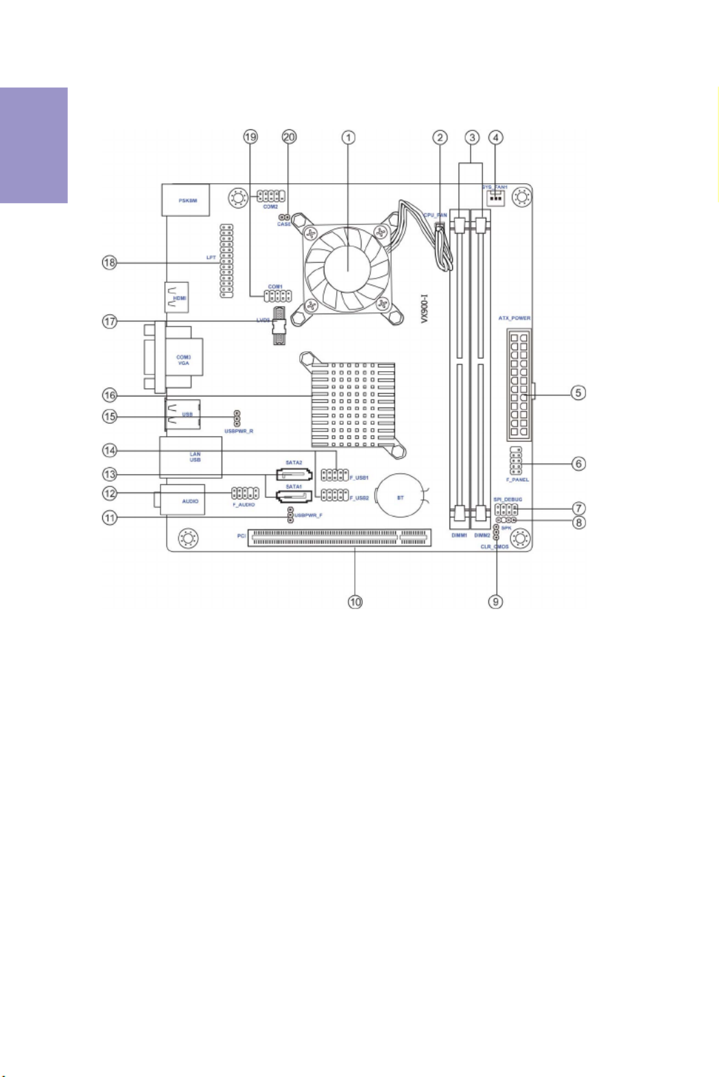
Motherboard Components

5
VX900-I USER MANUAL
Chapter 1
Table of Motherboard Components
LABEL COMPONENTS
1. CPU Onboard VIA® L2007
2. CPU_FAN 3-pin CPU cooling fan connector
3. DIMM_1~2 240-pin DDR3 Module slots
4. SYS_FAN 3-pin system cooling fan connector
5. ATX_POWER Standard 24-pin ATX power connector
6. F_PANEL Front panel switch/LED header
7. SPI_DEBUG SPI Debug header - for factory use only
8. SPK Speaker header
9. CLR_CMOS Clear CMOS jumper
10. PCI 32-bit add-on card slot
11. USBPWR_F Front panel USB power select jumper
12. F_AUDIO Front panel audio header
13. SATA1~2 Serial ATA 3.0 Gb/s connectors
14. F_USB1~2 Front panel USB 2.0 headers
15. USBPWR_R Rear USB/PS2 power select jumper
16. NB VX900 (colay VX900H)
17. LVDS 30-Pin one-channel LVDS connector (optional)
18. LPT Printer Header
19. COM1~2 Onboard serial port headers
20. CASE CASE open header

Chapter 1
6
VX900-I USER MANUAL
I/O Ports
1. PS/2 Mouse(green)
Use the upper PS/2 port to connect a PS/2 mouse.
2. PS/2 Keyboard(purple)
Use the lower PS/2 port to connect a PS/2 keyboard.
3. HDMI Port
You can connect the display device to the HDMI port.
4. COM Port
Use the COM port to connect serial devices such as Mouse or fax/modems.
5. VGA Port
Connect your monitor to the VGA port.
6. USB 2.0 Ports
Use the USB 2.0 ports to connect USB 2.0 devices.
7. LAN Port
Connect an RJ-45 jack to the LAN port to connect your computer to the Network.
8. Line-in(blue)
It can be connected to an external CD/DVD player, Tape player or other audio
devices for audio input.
9. Line-out(lime)
It is used to connect to speakers or headphones.
10. Microphone(pink)
It is used to connect to a microphone.
LAN LED Status Description
OFF No data
Orange blinking Active
OFF No link
Green Link
Activity LED
Link LED
Link LED
LAN Port

Chapter 2
8
VX900-I USER MANUAL
The following illustration shows the location of the motherboard jumpers. Pin 1 is
labeled.
1. To avoid the system instability after clearing CMOS, we recommend users to
enter the main BIOS setting page to “Load Default Settings” and then “Save
and Exit Setup”.
2. Make sure the power supply provides enough 5VSB voltage before selecting
the 5VSB function.
3. It is required that users place the USBPWR_F1 & USBPWR_R1 cap onto 2-3
pin rather than 1-2 pin as default if you want to wake up the computer by USB/
PS2 KB/Mouse.
2-3. Checking Jumper Settings
Chapter 2
9
VX900-I USER MANUAL
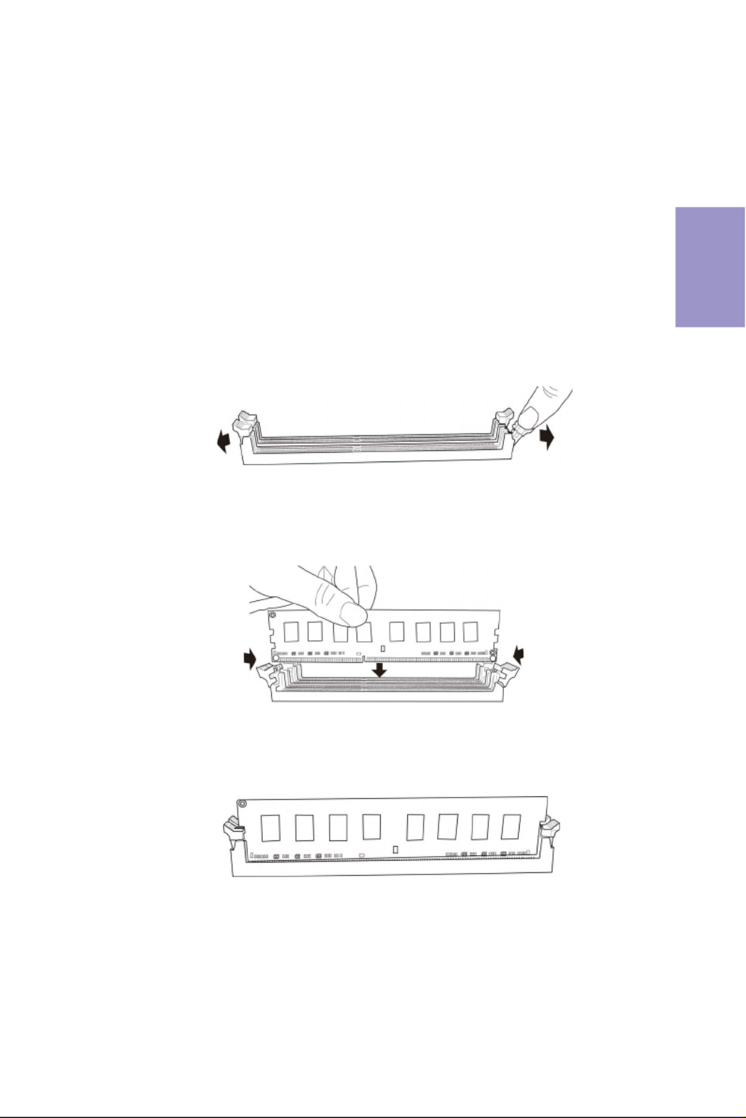
• This motherboard accommodates two memory modules. It can support
two 240-pin DDR3 1066.
• Do not remove any memory module from its antistatic packaging until
you are ready to install it on the motherboard. Handle the modules only
by their edges. Do not touch the components or metal parts. Always wear
a grounding strap when you handle the modules.
• You must install at least one module in any of the two slots. Total memory
capacity is 8 GB.
• Refer to the following to install the memory modules.
C. The slot latches are levered upwards and latch on to the edges of the
DIMM.
A. Push the latches on each side of the DIMM slot down.
B. Install the DIMM module into the slot and press it firmly down until it
seats correctly. Check that the cutouts on the DIMM module edge
connector match the notches in the DIMM slot.
2-4. Installing Hardware
2-4-1. Installing Memory Modules
Chapter 2
10
VX900-I USER MANUAL
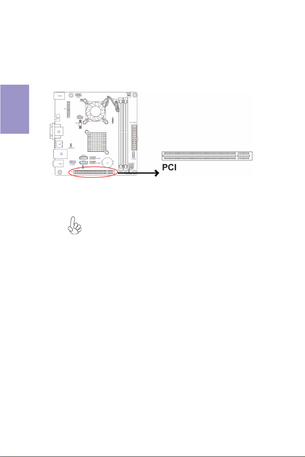
2-4-2. Installing Add-on Cards
The slots on this motherboard are designed to hold expansion cards and connect
them to the system bus. Expansion slots are a means of adding or enhancing the
motherboard’s features and capabilities. With these efficient facilities, you can
increase the motherboard’s capabilities by adding hardware that performs tasks
that are not part of the basic system.
Before installing an add-on card, check the documentation for
the card carefully. If the card is not Plug and Play, you may have
to manually configure the card before installation.
The PCI Express p14-x1 slot is fully compliant to the PCI Express Base
Specification revision 2.0.
PCIE Slot
Chapter 2
11
VX900-I USER MANUAL
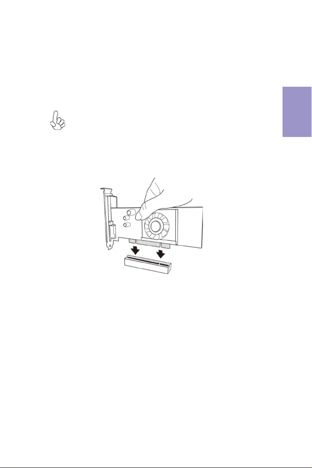
1 Remove a blanking plate from the system case corresponding to the slot
you are going to use.
2 Install the edge connector of the add-on card into the expansion slot.
Ensure that the edge connector is correctly seated in the slot.
3 Secure the metal bracket of the card to the system case with a screw.
1. For some add-on cards, for example graphics adapters and network adapt-
ers, you have to install drivers and software before you can begin using the
add-on card.
2. The onboard PCI interface does not support 64-bit SCSI cards.
Follow these instructions to install an add-on card:
Please refer the following illustrations to install the add-on card:
Install the VGA Card in the PCI slot
Chapter 2
12
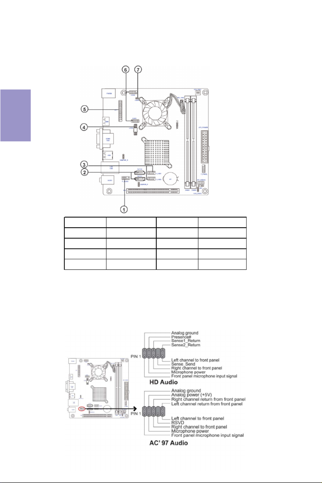
2-4-3. Connecting Optional Devices
Refer to the following for information on connecting the motherboard’s optional
devices:
No. Components No. Components
1 F_AUDIO 5 LPT
2 SATA1~2 6 COM
3 F_USB1~2 7 CASE
4 LVDS (optional) —— ——
The front panel audio header allows the user to install auxiliary front-oriented mi-
crophone and line-out ports for easier access. This header supports HD audio by
default. If you want connect an AC’97 front panel audio to HD onboard headers,
please set as below picture.
1. F_AUDIO: Front Panel Audio Header
Chapter 2
13
VX900-I USER MANUAL
If you use AC’97 Front Panel, please tick off the option of “Disabled Front Panel
Detect ”. If you use HD Audio Front Panel, please don’ “t tick off Disabled Front Panel
Detect ” .
* For reference only
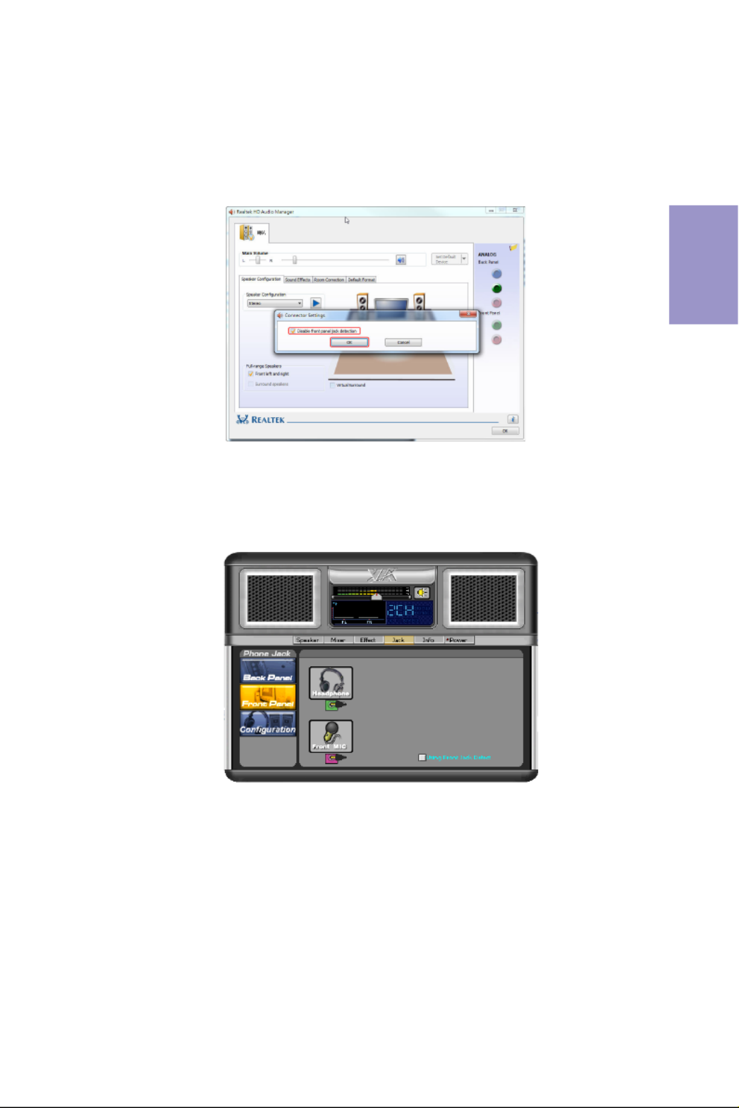
AC’97 Audio Configuration: To enable the front panel audio conne-ctor to
support AC97 Audio mode.
If you use AC’ 97 Front Panel, please don’ t tick off “Using Front Jack Detect ”. If you
use HD Audio Front Panel, please tick off the option of “Using Front Jack Detect ”.
* For reference only

Chapter 2
14
VX900-I USER MANUAL
SATA1/2 connectors support the Serial ATA 3.0Gb/s device. Simpler disk drive cabling
and easier PC assembly. It eliminates limitations of the current Parallel ATA inter-
face. But maintains register compatibility and sofeware compatibility with Parallel
ATA.
2. SATA1~2: Serial ATA connectors
The motherboard has two USB 2.0 headers supporting four USB 2.0 ports. Addition-
ally, some computer cases have USB ports at the front of the case. If you have this
kind of case, use auxiliary USB connector to connect the front-mounted ports to the
motherboard.
3. F_USB1~2: Front Panel USB 2.0 headers
Please make sure that the USB cable has the same pin assignment as indi-
cated above. A different pin assignment may cause damage or system hang-
up.

Chapter 2
16
VX900-I USER MANUAL
7. CASE: Chassis Intrusion Detect Header
This detects if the chassis cover has been removed. This function needs a chassis
equipped with instrusion detection switch and needs to be enabled in BIOS.
6. COM: Onboard serial port header
Connect a serial port extension bracket to this header to add a serial port to your
system.

Chapter 2
17
VX900-I USER MANUAL
2-4-4. Installing a SATA Hard Drive
This section describes how to install a SATA Hard Drive.
About SATA Connectors
Your motherboard features two SATA connectors supporting a total of four drives.
SATA refers to Serial ATA (Advanced Technology Attachment) is the standard interface
for the IDE hard drives which are currently used in most PCs. These connectors are
well designed and will only fit in one orientation. Locate the SATA connectors on the
motherboard and follow the illustration below to install the SATA hard drives.
Installing Serial ATA Hard Drives
To install the Serial ATA (SATA) hard drives, use the SATA cable that supports the Serial
ATA protocol. This SATA cable comes with a SATA power cable. You can connect either
end of the SATA cable to the SATA hard drive or the connector on the motherboard.
Refer to the illustration below for proper installation:
1 Attach either cable end to the connector on the motherboard.
2 Attach the other cable end to the SATA hard drive.
3 Attach the SATA power cable to the SATA hard drive and connect the other
end to the power supply.
* For reference only
Termékspecifikációk
| Márka: | ECS |
| Kategória: | alaplap |
| Modell: | VX900-I |
Szüksége van segítségre?
Ha segítségre van szüksége ECS VX900-I, tegyen fel kérdést alább, és más felhasználók válaszolnak Önnek
Útmutatók alaplap ECS

12 Január 2025
12 Január 2025
12 Január 2025
12 Január 2025
12 Január 2025
12 Január 2025
12 Január 2025
12 Január 2025
12 Január 2025
12 Január 2025
Útmutatók alaplap
- alaplap Sharkoon
- alaplap Gigabyte
- alaplap Asus
- alaplap Supermicro
- alaplap Biostar
- alaplap Asrock
- alaplap MSI
- alaplap NZXT
- alaplap Evga
- alaplap Intel
- alaplap Foxconn
- alaplap Advantech
- alaplap Elitegroup
- alaplap EPoX
Legújabb útmutatók alaplap

9 Április 2025
9 Április 2025
3 Április 2025
3 Április 2025
3 Április 2025
3 Április 2025
2 Április 2025
2 Április 2025
31 Március 2025
27 Március 2025