Használati útmutató ECS A890GXM-A2
Olvassa el alább 📖 a magyar nyelvű használati útmutatót ECS A890GXM-A2 (74 oldal) a alaplap kategóriában. Ezt az útmutatót 4 ember találta hasznosnak és 2 felhasználó értékelte átlagosan 4.5 csillagra
Oldal 1/74

Preface
Preface
Copyright
This publication, including all photographs, illustrations and software, is protected
under international copyright laws, with all rights reserved. Neither this manual, nor
any of the material contained herein, may be reproduced without written consent of
the author.
Version 1.0
Disclaimer
The information in this document is subject to change without notice. The manufac-
turer makes no representations or warranties with respect to the contents hereof and
specifically disclaims any implied warranties of merchantability or fitness for any
particular purpose. The manufacturer reserves the right to revise this publication and
to make changes from time to time in the content hereof without obligation of the
manufacturer to notify any person of such revision or changes.
Federal Communications Commission (FCC)
This equipment has been tested and found to comply with the limits for a Class B
digital device, pursuant to Part 15 of the FCC Rules. These limits are designed to
provide reasonable protection against harmful interference in a residential installa-
tion. This equipment generates, uses, and can radiate radio frequency energy and, if
not installed and used in accordance with the instructions, may cause harmful inter-
ference to radio communications. However, there is no guarantee that interference
will not occur in a particular installation. If this equipment does cause harmful
interference to radio or television reception, which can be determined by turning the
equipment off and on, the user is encouraged to try to correct the interference by one
or more of the following measures:
• Reorient or relocate the receiving antenna.
• Increase the separation between the equipment and the receiver.
• Connect the equipment onto an outlet on a circuit different from that to
which the receiver is connected.
• Consult the dealer or an experienced radio/TV technician for help.
Shielded interconnect cables and a shielded AC power cable must be employed with
this equipment to ensure compliance with the pertinent RF emission limits govern-
ing this device. Changes or modifications not expressly approved by the system’s
manufacturer could void the user’s authority to operate the equipment.
Trademark Recognition
Microsoft, MS-DOS and Windows are registered trademarks of Microsoft Corp.
AMD, Phenom, Athlon, Sempron and Duron are registered trademarks of AMD
Corporation.
Other product names used in this manual are the properties of their respective
owners and are acknowledged.

ii
Preface
Declaration of Conformity
This device complies with part 15 of the FCC rules. Operation is subject to the
following conditions:
• This device may not cause harmful interference.
• This device must accept any interference received, including interfer-
ence that may cause undesired operation.
Canadian Department of Communications
This class B digital apparatus meets all requirements of the Canadian Interference-
causing Equipment Regulations.
Cet appareil numérique de la classe B respecte toutes les exigences du Réglement sur
le matériel brouilieur du Canada.
About the Manual
The manual consists of the following:
Chapter 1
Introducing the Motherboard
Describes features of the motherboard.
Go to Hpage 1
Describes installation of motherboard
components.
Go to Hpage 7
Provides information on using the BIOS
Setup Utility.
Go to Hpage 23
Describes the motherboard software
Go to Hpage 43
Provides information about SATA RAID
Setup
Go to Hpage 47
Chapter 5
Setting Up AMD SB850 RAID
Configuration
page 67
Chapter 7
Trouble Shooting
Provides basic troubleshooting tips
Go to H
Chapter 6
Setting Up eJIFFY
Describes the eJIFFY setting up
Go to Hpage 55
Chapter 2
Installing the Motherboard
Chapter 3
Using BIOS
Chapter 4
Using the Motherboard Software

iii
TT
TTTABLE OF CONTENTSABLE OF CONTENTS
ABLE OF CONTENTSABLE OF CONTENTSABLE OF CONTENTS
Preface i
Chapter 1 1
Introducing the Motherboard 1
Introduction............................................................................................1
Features...................................................................................................2
Motherboard Components...................................................................5
Chapter 2 77777
Installing the Motherboard 7
Safety Precautions.................................................................................7
Choosing a Computer Case..................................................................7
Installing the Motherboard in a Case.................................................7
Installing Hardware............................................................................8
Installing the Processor...................................................................8
Installing Memory Modules...........................................................10
Expansion Slots.............................................................................12
Connecting Optional Devices........................................................14
Installing a SATA Hard Drive.......................................................16
Connecting I/O Devices......................................................................17
Connecting Case Components..........................................................18
Front Panel Header.......................................................................21
Chapter 3 23 23
23 23
23
Using BIOS 23
About the Setup Utility....................................................................23
The Standard Conguration..........................................................23
Entering the Setup Utility...............................................................23
Resetting the Default CMOS Values...............................................24
Using BIOS............................................................................................25
Standard CMOS Setup..................................................................26
Advanced Setup.............................................................................28
Advanced Chipset Setup................................................................30
Integrated Peripherals..................................................................31
Power Management Setup.............................................................32
PCI/PnP Setup...............................................................................33
PC Health Status...........................................................................33
M.I.B. III (MB Intelligent Bios)......................................................37

iv
Load Default Settings....................................................................40
Supervisor Password.....................................................................40
User Password...............................................................................41
Save & Exit Setup ..........................................................................41
Exit Without Saving........................................................................41
Updating the BIOS.........................................................................42
Chapter 4 43 43 43 43 43
Using the Motherboard Software 43
About the Software DVD-ROM/CD-ROM......................................43
Auto-installing under Windows XP/Vista/7....................................43
Running Setup...............................................................................44
Manual Installation............................................................................46
Utility Software Reference..................................................................46
Chapter 5 47 47
47 47 47
Setting Up AMD SB850 RAID Configuration 47
Setting Up a Bootable RAID Array..................................................47
Chapter 6 55 55
55 55 55
Setting Up eJIFFY 55
Introduction.......................................................................................55
Installation and BIOS Setup..............................................................56
Entering eJIFFY............................................................................................59
Features Icons...........................................................................................60
Usage FAQ..................................................................................................61
Chapter 7 67 67
67 67
67
Trouble Shooting 67
Start up problems during assembly....................................................67
Start up problems after prolong use..................................................68
Maintenance and care tips..................................................................68
Basic Troubleshooting Flowchart......................................................69

1
Introducing the Motherboard
Chapter 1
Introducing the Motherboard
Introduction
Thank you for choosing the A890GXM-A2 motherboard. This motherboard is a
high performance, enhanced function motherboard that supports socket for AMD
PhenomTM II/AthlonTM II/SempronTM processors (socket AM3) for high-end business
or personal desktop markets.
There is an advanced full set of I/O ports in the rear panel, including one VGA port,
one DVI port, one ESATA port, one HDMI port, one Display port, four USB2.0
ports, two USB3.0 ports, two LAN ports, one optical SPDIFO port and audio jacks
for microphone, line-in and 8-ch line-out.
The motherboard incorporates the AMD 890GX Northbridge (NB) and SB850
Southbridge (SB) chipsets. The Northbridge supports the HyperTransport
TM 3.0 in-
terface. The memory controller supports DDR3 memory DIMM frequencies of
1800 (OC)/1600 (OC)/1333/1066*1
. It supports four DDR3 slots with maximum
memory size of 32 GB*2. Two PCI Express x16 slot, intended for Graphics Interface,
are fully compliant to the PCI Express Gen2 (version 2.0). In addition, one PCI
Express p5-x1 slot is supported and one PCI Express p5-x4 slot which is PCI v2.0 compli-
ant is supported.
*2. Due to the DRAM maximum size (4 GB per dimm) at present, the
memory maximum size we have tested is 8 GB per dimm.
*1. Due to the limitation of AMD CPU spec, please refer to Memory QVL
for more information.
The SB850 Southbridge supports one PCI slot which is PCI v2.3 compliant. It
integrates USB 2.0 interface, supporting up to twelve USB2.0 ports (four USB ports
and four USB 2.0 headers support additional eight USB ports). The Southbridge
integrates a Serial ATA host controller, supporting five SATA ports with maximum
transfer rate up to 6 Gb/s each, and one eSATA3 6.0 Gb/s connector through the
bundled eSATA3 bracket.
In additon, the mainboard assembles extra USB3.0 chip, which suooprts two USB 3.0
ports with high speed of 5Gb/s.

2
Feature
Processor
HyperTransportTM Technology is a point-to-point link between two devices, it
enables integrated circuits to exchange information at much higher speeds than
currently available interconnect technologies.
• Accommodates AMD PhenomTM II/AthlonTM II/SempronTM processors
(socket AM3)
• Supports HyperTransportTM (HT) 3.0 interface speeds
This motherboard uses a socket AM3 that carries the following features:
SB850 (SB)
AMD 890GX
(NB)
• One p6-x4 A-Link Express III interface for connection to
an AMD Southbridge. The A-Link Express III is a propri-
etary interface developed by AMD basing on the PCI
Express technology, with additional Northbridge-
Southbridge messaging functionalities. It supports the
PCIe Gen 2 transfer rate of 5 GT/s, and is backward
compatible with the A-Link Express II interface.
• Supports two x16 PCI-Express Gen2 graphics link
• Fully supports ACPI states S1, S3, S4 and S5
• Supports ATI HyperMemory*.
Note: Includes dedicated and shared memory. The amount
of HyperMemory available is determined by various
factors. For details, please consult your AMD CSS
representative.
• Supports 16-bit up/down HyperTransport (HT) 3.0 in-
terface up to 4.8 GT/s.
The AMD 890GX Northbridge (NB) and SB850 Southbridge (SB) chipsets are
based on an innovative and scalable architecture with proven reliability and
performance.
Chipset
Memory
• Supports DDR3 1800 (OC)/1600 (OC)/1333/1066/800 DDR3 SDRAM
with Dual-channel architecture
• Compliant with PCI 2.3 specification at 33 MHz
• One-lane PCI Express® (PCIe®) 2.0 interface, sup-
porting up to two general purpose devices. Supported
configurations include: § 1x2 § 2x1
• Supports five Serial ATA devices which speeds up to
6 Gb/s
• Supports one eSATA3 which speeds up to 6.0 Gb/s
through the bundled eSATA3 bracket
• Integrated USB 3.0 Host Controller supporting up to
two USB 3.0 ports
• Integrated USB 2.0 Host Controller supporting up to
twelve USB 2.0 ports
• Supports integrated RAID 0, RAID 1, RAID 5, and RAID
10 functionality across all 5 ports (RAID 10 requires
use of 4 or more SATA ports, and RAID 5 requires use
of 3 or more SATA ports)

3
Expansion Options
• Two PCI Express x16 slots for Graphics Interface
• One PCI Express p7-x4 slot (the PCI-e x16 slot with black color)
• One PCI Express p7-x1 slot
• One 32-bit PCI v2.3 compliant slot
• Five 7-pin SATA connectors
Integrated I/O
The motherboard has a full set of I/O ports and connectors:
• One VGA port
• One DVI port
• One ESATA port
• One HDMI port
• One Display port
• Four USB 2.0 ports
• Two USB 3.0 blue ports
• Two LAN ports
• One optical SPDIFO port
• Audio jacks for microphone, line-in and 8-ch line-out
BIOS Firmware
• Power management
• Wake-up alarms
• CPU parameters
• CPU and memory timing
The firmware can also be used to set parameters for different processor clock
speeds.
The motherboard uses AMI BIOS that enables users to configure many sys-
tem features including the following:
1. Some hardware specifications and software items are subject to change
without prior notice.
2. Due to chipset limitation, we recommend that motherboard be operated in
the ambiance between 0 and 50°C.
Onboard LAN
• Supports PCI ExpressTM 2.0
• Integrated 10/100/1000 transceiver
• Wake-on-LAN and remote wake-up support
Audio
• 7.1+2 Channel High Definition Audio Codec
• Meets Microsoft WLP3.x (Windows Logo Program) audio require-
ments
• All DACs supports 44.1k/48k/96k/192kHz sample rate
• Software selectable 2.5V/3.2V/4.0V VREFOUT
• Direct Sound 3D. compatible
• Power Support: Digital: 3.3V; Analog: 5.0V
• Accommodates four unbuffered DIMMs
• Up to 8 GB per DIMM with maximum memory size up to 32 GB
The motherboard comes with the following expansion options

4
Introducing the Motherboard
• NB: AMD 890GX SB: SB850
•AMD PhenomTM II/AthlonTM II/SempronTM processors (socket
AM3)
• Supports “Hyper-Threading” technology CPU
• Dual-channel DDR3 memory architecture
• 4 x 240-pin DDR3 DIMM sockets support up to 32 GB
• Supports DDR3 1800 (OC)/1600 (OC)/1333/1066/800 DDR3
SDRAM
• 2 x PCI Express Gen2 x16 slots
• 1 x PCI Express p8-x4 slot(the black PCI Express x16 is band-
width of x4)
• 1 x PCI Express p8-x1 slot
• 1 x PCI slot
• Supported by AMD SB850 Express Chipset
• 5 x Serial ATA 6.0 Gb/s Host Controllers
• Supports RAID 0, 1, 5 and 10
• ALC892 8-Channel
• Dual Realtek 8111DL PCIE GigaLAN Controller
• 1 x VGA port
• 1 x DVI port
• 1 x ESATA port
• 1 x HDMI port
• 1 x Display port
• 4 x USB 2.0 ports
• 2 x USB 3.0 ports
• 2 x RJ45 LAN connectors
• 1 x Audio port (Line in, microphone in, line out, and optical
SPDIF out)
• 1 x 24-pin ATX Power Supply connector & ATX4P connector
& ATX8P connector.
• 5 x Serial ATA connectors
• 1 x eSATA3 6.0 Gb/s connector through the bundled eSATA3
bracket
• 4 x USB 2.0 headers support additional 8 USB ports
• 1 x Front panel header
• 1 x Chassis Intrusion Detect header
• 1 x SPDIF out header
• 1 x Front panel audio header
• 1 x Speaker header
• 1 x Reset button
• 1 x Power button
• 1 x CLR_COMS_ button
• CPU_FAN/SYS_FAN/PWR_FAN connectors
Chipset
Memory
Expansion
Slots
Storage
Audio
LAN
Rear Panel I/O
Internal I/O
Connectors &
Headers
• AMI BIOS with 8Mb SPI ROM
• Supports Plug and Play 1.0A, APM 1.2, Multi Boot, DMI
• Supports ACPI revision 1.0 specification
Form Factor • ATX Size, 305mm x 244mm
CPU
Specifications
System
BIOS

5
Introducing the Motherboard
Motherboard Components
The above image is for reference only; please take the actual
motherboard for detailed parts.

6
Introducing the Motherboard
Table of Motherboard Components
LABEL COMPONENTS
1. CPU Socket Socket for AMD PhenomTM II processor (socket AM3)
2. CPU_FAN CPU cooling fan connector
3. DDR3_1~4 240-pin DDR3 SDRAM slots
4. ATX_POWER Standard 24-pin ATX power connector
5. PWR_FAN Power cooling fan connector
6. CASE CASE open header
7. SATA1~5 Serial ATA connectors
8. SPK Speaker header
9. PANEL Front panel switch/LED header
10. PWR_BTN Power on button
11. RST_BTN Reset button
12. F_USB1~4 Front Panel USB headers
13. SYS_FAN System cooling fan connector
14. SPDIFO SPDIF out header
15. F_AUDIO Front panel audio header
16. PCI 32-bit add-on card slot
17. PCIE16X_T PCI Express p10-x4 slot
18. PCIE16X_S/PCIEX16 PCI Express x16 slots for graphics interface
19. PCIE PCI Express p10-x1 slot
20. ATX4P 4-pin ATX power connector
21. ATX12V 8-pin +12V power connector
This concludes Chapter 1. The next chapter explains how to install the motherboard.

7
Installing the Motherboard
Chapter 2
Installing the Motherboard
Safety Precautions
• Follow these safety precautions when installing the motherboard
• Wear a grounding strap attached to a grounded device to avoid dam-
age from static electricity
• Discharge static electricity by touching the metal case of a safely
grounded object before working on the motherboard
• Leave components in the static-proof bags they came in
• Hold all circuit boards by the edges. Do not bend circuit boards
Choosing a Computer Case
There are many types of computer cases on the market. The motherboard complies
with the specifications for the ATX system case. Some features on the motherboard
are implemented by cabling connectors on the motherboard to indicators and switches
on the system case. Make sure that your case supports all the features required. Make
sure that your case has sufficient power and space for all drives that you intend to
install.
Most cases have a choice of I/O templates in the rear panel. Make sure that the I/O
template in the case matches the I/O ports installed on the rear edge of the
motherboard.
This motherboard carries an ATX form factor of 305 X 244 mm. Choose a case that
accommodates this form factor.
Installing the Motherboard in a Case
Refer to the following illustration and instructions for installing the motherboard in
a case.
Most system cases have mounting brackets installed in the case, which correspond
the holes in the motherboard. Place the motherboard over the mounting brackets
and secure the motherboard onto the mounting brackets with screws.
Ensure that your case has an I/O template that supports the I/O ports and expansion
slots on your motherboard.

8
Installing the Motherboard
Do not over-tighten the screws as this can stress the motherboard.
Installing Hardware
Installing the Processor
Caution: When installing a CPU heatsink and cooling fan make sure that
you DO NOT scratch the motherboard or any of the surface-mount resis-
tors with the clip of the cooling fan. If the clip of the cooling fan scrapes
across the motherboard, you may cause serious damage to the motherboard
or its components.
On most motherboards, there are small surface-mount resistors near the
processor socket, which may be damaged if the cooling fan is carelessly
installed.
Avoid using cooling fans with sharp edges on the fan casing and the clips.
Also, install the cooling fan in a well-lit work area so that you can clearly
see the motherboard and processor socket.

9
Installing the Motherboard
This motherboard has a socket AM3 processor socket. When choosing a processor,
consider the performance requirements of the system. Performance is based on the
processor design, the clock speed and system bus frequency of the processor, and the
quantity of internal cache memory and external cache memory.
Before installing the Processor
This motherboard automatically determines the CPU clock frequency and system
bus frequency for the processor. You may be able to change these settings by making
changes to jumpers on the motherboard, or changing the settings in the system Setup
Utility. We strongly recommend that you do not over-clock processors or other
components to run faster than their rated speed.
Warning:
1. Over-clocking components can adversely affect the reliability of the
system and introduce errors into your system. Over-clocking can perma-
nently damage the motherboard by generating excess heat in components
that are run beyond the rated limits.
2. Always remove the AC power by unplugging the power cord from the
power outlet before installing or removing the motherboard or other hard-
ware components.

10
Installing the Motherboard
1 Install your CPU. Pull up the lever away from
the socket and lift up to 90-degree angle.
2 Locate the CPU cut edge (the corner with
the pin hold noticeably missing). Align and
insert the CPU correctly.
3 Press the lever down and apply thermal
grease on top of the CPU.
4 Put the CPU Fan down on the retention mod-
ule and snap the four retention legs of the
cooling fan into place.
5 Flip the levers over to lock the heat sink in
place and connect the CPU cooling Fan power
cable to the CPUFAN connector. This com-
pletes the installation.
CPU Installation Procedure
The following illustration shows CPU installation components.
To achieve better airflow rates and heat dissipation, we suggest that you
use a high quality fan with 4800 rpm at least. CPU fan and heatsink
installation procedures may vary with the type of CPU fan/heatsink sup-
plied. The form and size of fan/heatsink may also vary.
Installing Memory Modules
This motherboard accommodates four memory modules. It can support four 240-pin
DDR3 1800 (OC)/1600 (OC)/1333/1066/800. The total memory capacity is 32 GB.
DDR3 SDRAM memory module table
Do not remove any memory module from its antistatic packaging until
you are ready to install it on the motherboard. Handle the modules only
by their edges. Do not touch the components or metal parts. Always
wear a grounding strap when you handle the modules.
You must install at least one module in any of the four slots. Each module can be
installed with 8 GB of memory.
Memory module Memory Bus
DDR3 1066 533 MHz
1. Due to the limitation of AMD CPU spec, please refer to Memory QVL
for more information.
*
DDR3 1333 667 MHz
DDR3 1600 800 MHz
DDR3 1800 900 MHz
* For reference only

11
Installing the Motherboard
Installation Procedure
Refer to the following to install the memory modules.
1 This motherboard supports unbuffered DDR3 SDRAM only.
2 Push the latches on each side of the DIMM slot down.
3 Align the memory module with the slot. The DIMM slots are keyed with
notches and the DIMMs are keyed with cutouts so that they can only be
installed correctly.
4 Check that the cutouts on the DIMM module edge connector match the
notches in the DIMM slot.
5 Install the DIMM module into the slot and press it firmly down until it
seats correctly. The slot latches are levered upwards and latch on to
the edges of the DIMM.
6 Install any remaining DIMM modules.
For best performance and compatibility, we recommend that users install
DIMMs in the sequence of DIMM3, DIMM4, DIMM1 and DIMM2.
* For reference only
12
Installing the Motherboard
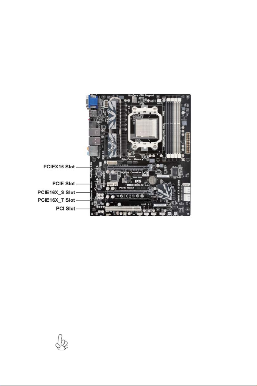
Expansion Slots
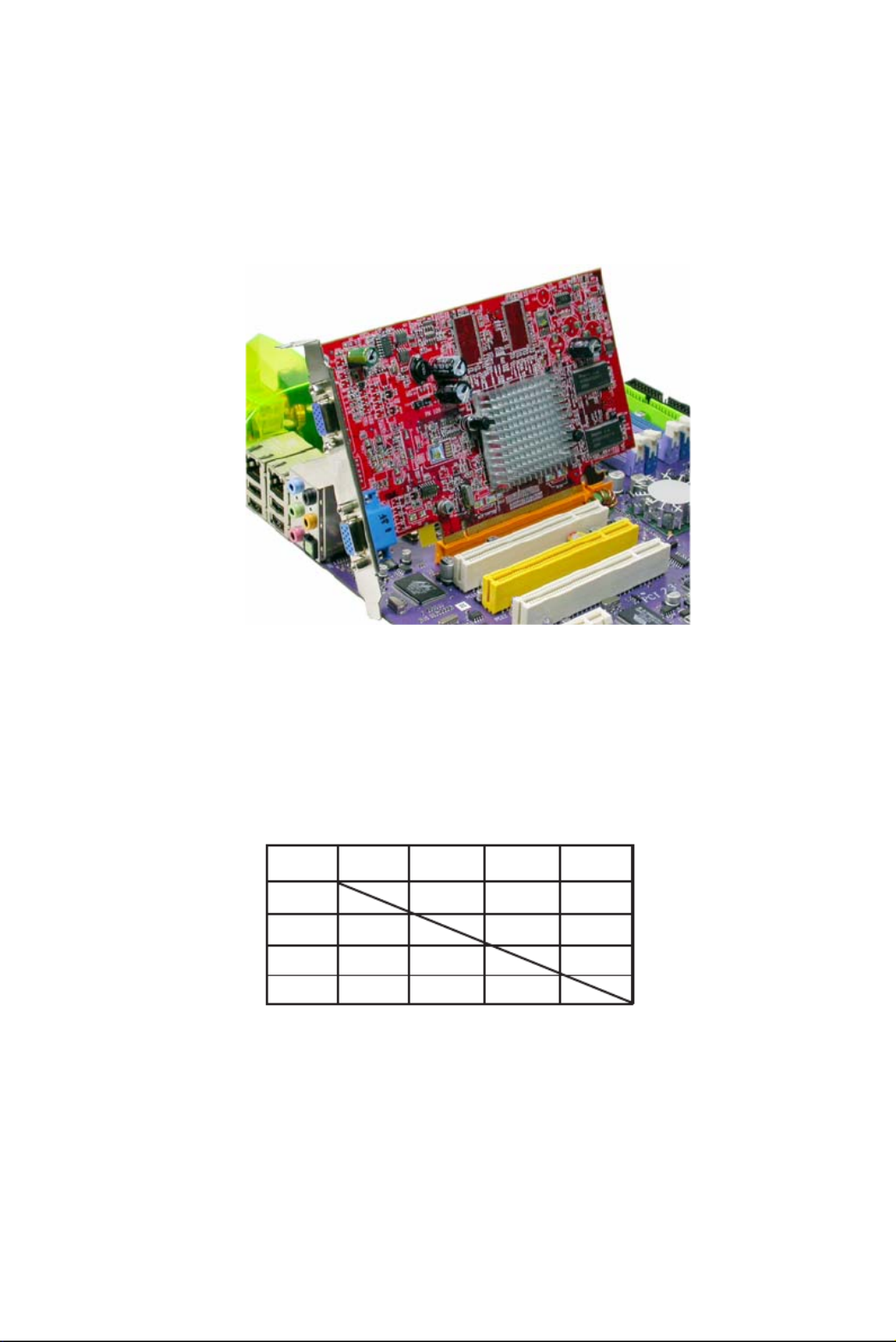
Installing Add-on Cards
The slots on this motherboard are designed to hold expansion cards and connect
them to the system bus. Expansion slots are a means of adding or enhancing the
motherboard’s features and capabilities. With these efficient facilities, you can in-
crease the motherboard’s capabilities by adding hardware that performs tasks that are
not part of the basic system.
P C I E X 1 6 /
P C I E 1 6 X _ S
Slots
PCI Slot This motherboard is equipped with one standard PCI slot.
PCI stands for Peripheral Component Interconnect and is a
bus standard for expansion cards, which for the most part, is
a supplement of the older ISA bus standard. The PCI slot on
this board is PCI v2.3 compliant.
The PCI Express p16-x1 slots are fully compliant to the PCI
Express Gen2 (version 2.0).
PCIE Slots
Before installing an add-on card, check the documentation
for the card carefully. If the card is not Plug and Play, you
may have to manually configure the card before installa-
tion.
The PCI Express x16 slot is used to install an external PCI
Express graphics card that is fully compliant to the PCI
Express Gen2 (version 2.0).
The PCI Express p16-x4 slot is fully compliant to the PCI Ex-
press Base Specification revision 2.0.
PCIE16X _ T
Slot
(PCIEX4 Slot)
13
Installing the Motherboard
DP HDMI DVI D-Sub
HDMI O X O
DP O
DVI O X O
D-Sub O
Follow these instructions to install an add-on card:
1 Remove a blanking plate from the system case corresponding to the
slot you are going to use.
2 Install the edge connector of the add-on card into the expansion slot.
Ensure that the edge connector is correctly seated in the slot.
3 Secure the metal bracket of the card to the system case with a screw.
* For reference only
O O
OO
Notice to User:
1. When use some add-on cards on this motherboard, please install the required
driver and software first.
2. Graphics outputs matrix as follows:
Ex: using DP, user can use HDMI or DVI or D-Sub at the same time.
Note:
1. Only two graphics outputs (DP,HDMI,DVI,D-Sub) can be displayed at the same
time
2. DVI and HDMI share the same signal, so they can not be used at the same time.
3. Display port and the first PCI E X16 slot (the closest to CPU) share the same
signal, so they can not be used at the same time.
4. The first PCI E X16 slot (the closest to CPU) only supports PCI E X16 Cards.

14
Installing the Motherboard
SPDIFO: SPDIF out header
This is an optional header that provides an S/PDIF (Sony/Philips Digital Interface)
output to digital multimedia device through optical fiber or coaxial connector.
Connecting Optional Devices
Refer to the following for information on connecting the motherboard’s optional
devices:
SATA1~5: Serial ATA connectors
These connectors are used to support the new Serial ATA devices for the highest data
transfer rates (6.0 Gb/s), simpler disk drive cabling and easier PC assembly. It elimi-
nates limitations of the current Parallel ATA interface. But maintains register com-
patibility and software compatibility with Parallel ATA.
1Ground 2 TX+
3TX- 4 Ground
5RX- 6 RX+
7 -Ground -
Pin Signal Name Pin Signal Name
2+5VA 5V analog Power
3 Key No pin
4 GND Ground
Pin Signal Name Function
1SPDIF SPDIF digital output

15
Installing the Motherboard
F_AUDIO: Front Panel Audio header
This header allows the user to install auxiliary front-oriented microphone and line-
out ports for easier access.
F_USB1~4: Front Panel USB headers
The motherboard has six USB ports installed on the rear edge I/O port array. Addi-
tionally, some computer cases have USB ports at the front of the case. If you have
this kind of case, use auxiliary USB connector to connect the front-mounted ports to
the motherboard.
Please make sure that the USB cable has the same pin assignment as
indicated above. A different pin assignment may cause damage or system
hang-up.
1USBPWR Front Panel USB Power
2USBPWR Front Panel USB Power
3USB_FP_P0- USB Port 0 Negative Signal
4USB_FP_P1- USB Port 1 Negative Signal
5USB_FP_P0+ USB Port 0 Positive Signal
6USB_FP_P1+ USB Port 1 Positive Signal
7GND Ground
8GND Ground
9Key No pin
10 USB_FP_OC0 Overcurrent signal
FunctionPin Signal Name
Pin Signal Name Function
1 2PORT 1L AUD_GND
3PORT 1R 4 PRESENCE#
5PORT 2R 6 SENSE1_RETURN
7SENSE_SEND 8 KEY
Pin Signal Name
9PORT 2L 10 SENSE2_RETURN
Pin Signal Name
CASE: Chassis Intrusion Detect Header
Short Chassis cover is removed
Open Chassis cover is closed
Pin 1-2 Function
This detects if the chassis cover has been removed. This function needs a chassis
equipped with instrusion detection switch and needs to be enabled in BIOS.

16
Installing the Motherboard
Refer to the illustration below for proper installation:
This motherboard supports the “Hot-Plug” function.
1 Attach either cable end to the connector on the motherboard.
2 Attach the other cable end to the SATA hard drive.
3 Attach the SATA power cable to the SATA hard drive and connect the
other end to the power supply.
Installing a SATA Hard Drive
This section describes how to install a SATA hard drive.
About SATA Connectors
Your motherboard features five SATA connectors supporting a total of f drives.ive
SATA refers to Serial ATA (Advanced Technology Attachment) is the standard inter-
face for the IDE hard drives which are currently used in most PCs. These connectors
are well designed and will only fit in one orientation. Locate the SATA connectors on
the motherboard and follow the illustration below to install the SATA hard drives.
Installing Serial ATA Hard Drives
To install the Serial ATA (SATA) hard drives, use the SATA cable that supports the
Serial ATA protocol. This SATA cable comes with an SATA power cable. You can
connect either end of the SATA cable to the SATA hard drive or the connector on the
motherboard.
SATA cable (optional) SATA power cable (optional)
* For reference only

17
Installing the Motherboard
Connecting I/O Devices
The backplane of the motherboard has the following I/O ports:
USB3.0 Ports Use the USB3.0 ports to connect USB3.0 devices.
LAN Port Connect an RJ-45 jack to the LAN port to connect your
computer to the network.
VGA Port Connect your monitor to the VGA port.
DVI Port Use the DVI port to connect the monitor.
ESATA Port Use this port to connect to external SATA boxes or Serial
ATA port multipliers.
Before connecting the eSATA cables, make sure to turn off
the power of the external enclosure.
DIS Port(Dispaly
Port)
CLR_COMS_BTN Use the CLR_CMOS button to clear CMOS.
Audio Ports Use the audio jacks to connect audio devices. The C port is
for stereo line-in signal, while the E port is for microphone
in signal. This motherboard supports audio devices that cor-
respond to the A, B and D port respectively. In addition, all
of the 3 ports, B, and D provide users with both right & left
channels individually. Users please refer to the following
note for specific port function definition.
This jack connects to external optical digital audio output
devices.
Optical SPDIF
Output
The above port definition can be changed to audio input or
audio output by changing the driver utility setting.
A: Center & Woofer D: Front Out
B: Back Surround E: Mic_in Rear
C: Line-in -
Use the Display port to connect the monitor.
HDMI Port Connect the HDMI port to the HDMI devices.
USB Ports Use the USB ports to connect USB devices.

18
Installing the Motherboard
Connecting Case Components
After you have installed the motherboard into a case, you can begin connecting the
motherboard components. Refer to the following:
1 Connect the CPU cooling fan cable to CPU_FAN.
2 Connect the standard power supply connector to ATX_POWER.
3 Connect the case speaker cable to SPK.
4 Connect the case switches and indicator LEDs to the PANEL.
5 Connect the system cooling fan connector to SYS_FAN.
6 Connect the auxiliary case power supply connector to ATX12V.
7 Connect the power cooling fan connector to PWR_FAN.
8 Connect the the auxiliary power connector for graphics interface to
ATX4P.
Users please note that the 24-pin power cable can be connected to the
ATX_POWER connector.
With ATX v2.x power supply, users please
note that when installing 24-pin power
cable, the latches of power cable and the
ATX_POWER match perfectly.
Connecting 24-pin power cable
24-pin power cable
* For reference only

19
Installing the Motherboard
CPU_FAN: Cooling FAN Power Connector
Users please note that the fan connector supports the CPU cooling
fan of 1.1A~2.2A (26.4W max.) at +12V.
1GND System Ground
2+12V Power +12V
3Sense Sensor
4PWM CPU FAN control
Function
Pin Signal Name
ATX_POWER: ATX 24-pin Power Connector
1+3.3V 13 +3.3V
2+3.3V 14 -12V
3Ground 15 COM
4+5V 16 PS_ON
5Ground 17 COM
6+5V 18 COM
7Ground 19 COM
8PWRGD 20 -5V
9+5VSB 21 +5V
10 +12V 22 +5V
11 +12V 23 +5V
12 +3.3V 24 COM
Pin Signal Name Pin Signal Name
When installing 4-pin power cable, the
latch falls on the left side of the
ATX12V connector.
4-pin power cable
Users please note that the 8-pin and 4-pin power cables can both be con-
nected to the ATX12V connector.
When installing 8-pin power cable, the
latches of power cable and the ATX12V
connector match perfectly.
Connecting 8/4-pin power cable
8-pin power cable
* For reference only
* For reference only
Termékspecifikációk
| Márka: | ECS |
| Kategória: | alaplap |
| Modell: | A890GXM-A2 |
Szüksége van segítségre?
Ha segítségre van szüksége ECS A890GXM-A2, tegyen fel kérdést alább, és más felhasználók válaszolnak Önnek
Útmutatók alaplap ECS

12 Január 2025
12 Január 2025
12 Január 2025
12 Január 2025
12 Január 2025
12 Január 2025
12 Január 2025
12 Január 2025
12 Január 2025
12 Január 2025
Útmutatók alaplap
- alaplap Sharkoon
- alaplap Gigabyte
- alaplap Asus
- alaplap Supermicro
- alaplap Biostar
- alaplap Asrock
- alaplap MSI
- alaplap NZXT
- alaplap Evga
- alaplap Intel
- alaplap Foxconn
- alaplap Advantech
- alaplap Elitegroup
- alaplap EPoX
Legújabb útmutatók alaplap

9 Április 2025
9 Április 2025
3 Április 2025
3 Április 2025
3 Április 2025
3 Április 2025
2 Április 2025
2 Április 2025
31 Március 2025
27 Március 2025